automatic and scalable cloud framework for parametric studies using scientific...
TRANSCRIPT

IT 16 065
Examensarbete 30 hpSeptember 2016
Automatic and scalable cloud framework for parametric studies using scientific applications
Virakraingsei Hai Socheat
Institutionen för informationsteknologiDepartment of Information Technology

Teknisk- naturvetenskaplig fakultet UTH-enheten Besöksadress: Ångströmlaboratoriet Lägerhyddsvägen 1 Hus 4, Plan 0 Postadress: Box 536 751 21 Uppsala Telefon: 018 – 471 30 03 Telefax: 018 – 471 30 00 Hemsida: http://www.teknat.uu.se/student
Abstract
Automatic and scalable cloud framework forparametric studies using scientific applications
Virakraingsei Hai Socheat
Many scientific applications are computationally expensive and often require a largepool of resources for large scale experiments within a reasonable time frame. WithCloud computing offers a new model of consuming computing infrastructures fortheir flexible application deployment. At the same time, microservice architecture hasalso gained momentum in the industries for a number of reasons including minimaloverhead, simplicity, flexibility, scalability and resilience. The combination of the twotechnologies has the potential to bring large benefits for scientists and researchers.The goal of this project is to develop a framework which can help to facilitateresearchers and scientists to develop their microservices and to provide a hostingplatform for parallel execution of their applications.
Tryckt av: Reprocentralen ITCIT 16 065Examinator: Mats DanielsÄmnesgranskare: Salman ToorHandledare: Andreas Hellander

Acknowledgments The completion of this thesis could not have been possible without the guidance from my supervisor Andreas Hellander and my reviewer Salman Toor. I would like to thank my colleagues at DCA group and friends who have been a great help in reviewing my thesis.
A debt of gratitude to the Swedish Institute for the financial support for my study at Uppsala University.

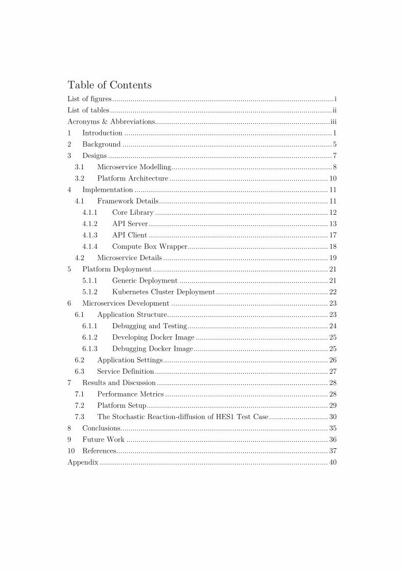
Table of Contents List of figures ............................................................................................................. i List of tables ............................................................................................................. ii Acronyms & Abbreviations ...................................................................................... iii 1 Introduction ...................................................................................................... 1 2 Background ....................................................................................................... 5 3 Designs .............................................................................................................. 7
3.1 Microservice Modelling ............................................................................... 8 3.2 Platform Architecture .............................................................................. 10
4 Implementation ............................................................................................... 11 4.1 Framework Details ................................................................................... 11
4.1.1 Core Library ..................................................................................... 12 4.1.2 API Server ........................................................................................ 13 4.1.3 API Client ........................................................................................ 17 4.1.4 Compute Box Wrapper ..................................................................... 18
4.2 Microservice Details ................................................................................. 19 5 Platform Deployment ...................................................................................... 21
5.1.1 Generic Deployment ......................................................................... 21 5.1.2 Kubernetes Cluster Deployment ....................................................... 22
6 Microservices Development ............................................................................. 23 6.1 Application Structure ............................................................................... 23
6.1.1 Debugging and Testing ..................................................................... 24 6.1.2 Developing Docker Image ................................................................. 25 6.1.3 Debugging Docker Image .................................................................. 25
6.2 Application Settings ................................................................................. 26 6.3 Service Definition ..................................................................................... 27
7 Results and Discussion .................................................................................... 28 7.1 Performance Metrics ................................................................................ 28 7.2 Platform Setup ......................................................................................... 29 7.3 The Stochastic Reaction-diffusion of HES1 Test Case ............................. 30
8 Conclusions...................................................................................................... 35 9 Future Work ................................................................................................... 36 10 References ........................................................................................................ 37 Appendix ................................................................................................................ 40

i
List of figures
Figure 1: Paas environment ...................................................................................... 7 Figure 2: A ComputeApp- Calculator ...................................................................... 9 Figure 3: Multiple Replication of a compute app “Calculator” ................................ 9 Figure 4: Platform Architecture ............................................................................. 11 Figure 5: Framework Architecture ......................................................................... 11 Figure 6: Database Schema .................................................................................... 13 Figure 7: AddComputePodLogic ............................................................................ 16 Figure 8: Service to URL mapping ......................................................................... 18 Figure 9: Service Resolver....................................................................................... 19 Figure 10: Generic Deployment Architecture ......................................................... 21 Figure 11: Kubernetes-base cluster deployment ...................................................... 22 Figure 12: The three stages of microservice development ....................................... 23 Figure 13: Airfoil Simulation .................................................................................. 24 Figure 14: Developing a Docker image ................................................................... 25 Figure 15: Service Definition .................................................................................. 27 Figure 16: Kubernetes service and pod representation ........................................... 28 Figure 17: The platform architecture for testing .................................................... 29 Figure 18: Feedback loop of HES1 .......................................................................... 30 Figure 19: Speedup ratio for various pod setups ..................................................... 31 Figure 20: Parallel efficiency for different pod configurations ................................. 32 Figure 21: Load balancing for different setup ......................................................... 33 Figure 22: Request timeline .................................................................................... 34

ii
List of tables
Table 1: Logic return's types .................................................................................. 16 Table 2: Parameter Types ...................................................................................... 19 Table 3: Microservice's default fields ...................................................................... 20 Table 4: Parameter Configurations ......................................................................... 30 Table 5: Application Settings’ Default Value ......................................................... 40 Table 6: Global Constants ...................................................................................... 40 Table 7: Speedup Ratio .......................................................................................... 42

iii
Acronyms & Abbreviations
API Application Program Interface AWS Amazon Web Services bHLH basic helix–loop–helix CRUD Create Read Update Delete GRN Gene Regulatory Network HES1 Hairy and Enhancer of Split-1 HPC High Performance Computing HTTP Hypertext Transfer Protocol IaaS Infrastructure as a Service MPI Message Passing Interface MPMD Multiple Program Multiple-Data MVC Model-View-Controller PaaS Platform as a Service REST Representational State Transfer SaaS Software as a Service SNIC Swedish National Infrastructure for Computing SPMD Single Program Multiple-Data VM Virtual Machine

1
1 Introduction Scientific computing is a multidisciplinary field that aims to solve scientific, social and engineering problems by constructing mathematical models and finding the numerical solution to solve them. Such problems involve the integration of various models that simulate various aspects of complex phenomena. The aggregation of results from multiple runs of a simulation provides scientists with systematic ways to virtually explore in details the physical, mathematical and computational aspects of the problem. Such explorations are commonly used for both scientific understanding and design purposes including, for example, parametric study, optimizations and sensitivity analysis.
Parametric study is predominant simulation workflow where the control parameter space is explored to optimize an objective function that captures system realizability, cost, performance or a combination thereof [1]. Such methods typically exploit coarse-grained parallelism because the application is executed multiple times using unique sets of input parameters values whose range and increments are specified. Since the number of the combination is usually enormous, High Performance Computing (HPC) infrastructures have been used to accelerate such studies and produce more accurate and optimal outcomes [3][10][14]. These types of infrastructures are both expensive and technically challenging. Some researchers and scientists need to specifically program their models or applications according to the supported engine’s requirements. This requires the users to redesign their applications or experiments in order to use the services.
The capability of HPC has been pushing scientific interest toward coupled multiphysics simulations which permit even more faithful and more detailed of modelling of many complex physical systems [2]. Such applications can be in the form of single program multiple-data (SPMD) or multiple-program multiple-data (MPMD). The algorithmic coupling is strong in SPMD in which the parallel processes need some special communication library, such as Message Passing Interface (MPI). It is considered to be the serial part that presents a bottleneck for parallel speedup. In contrast to SPMD, MPMD has a weaker algorithmic coupling enable separation between different physical phenomena which allows them to be run concurrently. This approach allows different components to be written in different languages and some existing components can be reused. The MPMD applications declares their

2
resource requirements to a distributed software system such as HPC or Grids where parallel execution will help speed up their performance.
In recently years, the advancement of virtualization technology has led to a computing paradigm called “Cloud Computing”. It has a large pool of compute resources and storages which are connected to dynamically deliver the on-demand computing resources to the users. Cloud computing consists of three main models: Software as a Service (SaaS), Platform as a Service (PaaS) and Infrastructure as a Service (IaaS). These models provide a great deal of flexibility in setting up a compute infrastructure and application deployment. Currently, many established companies such as Google, Microsoft and Amazon are offering cloud services. These public cloud service providers offer users the ability to customize their cloud solutions through configurations and flexible pricing scheme (pay per use or subscription fee). In many academic intuitions, there exist computing infrastructures which can be mounted by cloud provisioning tools that can transform them into cloud platforms.
Another trend that has emerged and gained popularity in the IT industry is “Microservices”. It is an architecture style and a lightweight service type of RESTful (Representational State Transfer) web service in which large complex software applications are composed of one or more services. They can be deployed independently of one another and are loosely coupled. It shares many similarities with SOA (Service-oriented architecture). Microservices provide a plethora of benefits such as simpler codebases for individual services, isolation, scalability and enabling programming language diversity [5]. For decades, many simulation models and software were written as monolithic application models where all logics used for user interface, the business rules and the manipulation of the data are in a single layer. This type of application is tightly coupled and a simple change could lengthen development cycles before it can have more rigorous testing. Moreover, the applications are built on statically-assigned resources and highly-available hardware made them susceptible to variations in load and hardware performance. The entire application could send into tailspin if there was an outright hardware failure. Unlike monolithic applications, microservices are made up by many independent components that work in concert to deliver the application’s overall functionality. They enable the separation of the application from the underlying infrastructure on which it runs and this makes it perfectly suitable to the agility, scale and reliability requirements of many applications and simulations. Microservices can scale independently allowing application to adapt to changing loads. These benefits should

3
not be overlooked by the scientists and researchers. Turning scientific application into microservices is neither straightforward nor difficult. The existing applications that were developed by using MPMD approach is easier than SPMD because of their loosely coupled architecture. For SPMD or normal applications they are most likely need some modifications depending on their original designs and architecture. Despite some extra efforts in designing loosely couple scientific algorithms or applications and turning them into microservices, the benefits that they will bring back are outweighed as it will help to promote the reusability of various loose coupling components and allow them to span dynamically according to the availability of resources and the fidelity of desired parallelism.
By recognising the advantages that microservices can bring to the scientific computing community, this project aims to produce a framework capable of turning applications into microservices. Together with other opensource technologies such as CoreOS, Kubernetes, and Docker, the framework will also provide a platform-as-a-service for hosting these microservices making it highly advantageous for parallel execution. Therefore, the objectives of this project are:
- To provide users a framework for cloud-based application deployment - To implement a platform for parallel execution of applications - To allow users to develop scientific microservices with less time and effort - To assess the parallel overheads and the parallel efficiency of the building
platform for running computationally intensive microservices.
Microservices have been around in this industry for a while and they have drawn attention from many well established companies. In 2014, IBM introduced a cloud platform-as-a-service (Paas) called IBM Bluemix. This platform is used for building, running and managing applications. It supports a variety of runtime environments including Java, Javascript, GO, PHP, Python, Ruby and Scala. Along with the runtime environments, IBM Bluemix also supports containers and virtual machines (VMs). A number of ready-made applications are also offered to users in order to accelerate the development and enhance the reusability. A book of guidelines on how to develop microservices in IBM Bluemix was published in August 2015 by its technology team [4]. Based on the guidelines given and functionalities of the platform, users must have some understanding of developing microservices in one of the supported environments. Also, they need to familiarize themselves with the management console of their cloud system.

4
Another microservice platform called Mantl from Cisco was recently released aiming at providing to users a full-stack microservice platform by incorporating many components such as service discovery, cluster management, container runtime, orchestration, proxy, and cloud provisioning tool. It is a rich microservice platform where productivity and throughput are optimized. There is a differences between Mantl and the developing framework of this project. Mantl targets microservice platform and microservice deployment but not microservice development. This means that scientists and researchers will not only require to learn how to write their microservices but also need to master Mantle and their components in order to run their simulation application smoothly with the desired functionalities which have been described above.
Many major cloud providers such as Google, Azure, and AWS also provide platforms for hosting and managing microservices as well. They are called App Engine, Service Fabric, and AWS Lambda respectively. These platforms support multiple language runtimes and offer a rich experience in developing, deployment and maintenance of microservices. They are designed for hosting massively scalable applications that are self-healing. However, users need to develop microservices from scratch and most of the time the development span across multiple cloud solutions which requires in depth knowledge in a particular cloud provider. Moreover, these services are not free.

5
2 Background In this section, related tools and technologies will be described in brief. They will be used in this implementing framework. Some of the tools will be used for platform deployment.
A. Openstack Openstack is a collection of open source components used to build a scalable cloud platform and is known as IaaS [18]. It can offer elasticity and horizontal scalability and it is the most popular cloud platform among many well-known platforms in cloud computing technology. Openstack is used by SNIC (Swedish National Infrastructure for Computing) Science Cloud in collaboration with four major scientific research centres throughout Sweden. The framework will be deployed in this platform.
B. Docker Docker is an open platform for building, shipping and automating the deployment of application inside Linux containers. Linux container is an operating system level virtualization environment for running multiple isolated Linux systems on a single Linux control host. It does not run its own Linux or require a hypervisor and therefore they have almost no performance overhead. Containers are flexible, fast, short-lived and fragile. Since they are not full VMs, they need a lot of orchestration to run efficiently and resiliently.
C. CoreOS This is an open-source lightweight operating system based on Linux kernel and targets cloud environments. It is shipped with Docker and a collection of useful tools for operating services in the cloud such as etcd, rkt, fleet and flannel. CoreOS requires a very minimal configuration compared to other standard Linux distribution for clustering in the cloud environment.
D. Kubernetes Kubernetes is an open platform for automating deployment, scaling and operations of application containers in a cluster environment. It is lightweight system which orchestrates the containers and provides scalability and load balancing. Its core features include automatic binpacking, self-healing, horizontal scaling, service discovery and load balancing, automated rollouts and rollbacks, secret and configuration management, storage orchestration and batch execution. Kubernetes is very beneficial for applications of specific-workflows for its ad hoc orchestration is very robust. The term K8s is used interchangeably with Kubernetes.

6
E. Django framework Django is a free and open source web framework designed to support the development of web application including web services, web resources and web APIs. It follows MVC (Model-View-Controller) architecture and is written in Python.
7
3 Designs By definition, Platform-as-a-service (PaaS) helps users to isolate the complex processes of building and maintaining the infrastructure for application deployment. The building platform targets for building and deployment of microservices. It should support multitenancy support which can protect those microservices from unauthorized access. As shown in figure 1, users can deploy their microservices to the platform through a manager or API Server in the actual implementation. The API Server plays a crucial role in managing the whole platform. It contains user, cluster, container and microservices management module. We will discuss the API Sever in detail in the implementation section.
As mentioned earlier, the microservice is the only type of application that will be hosted in this platform. A Docker container will be used to deploy microservices. This explicitly implies that the API Server can only deploy microservices that are already prepared and packaged inside a Docker container. This approach may render the end user uncomfortable as it presumes their knowledge of building and packaging microservices into a Docker container. However, Docker engine is a fairly simple engine which requires some basic knowledges in package and library installation in Linux environments. Having simplicity and rapid deployment as the design goals, the building platform also abstracts some of the very few complexities exhibited by the Docker engine. The process of running a Docker container can be done by using a specific Docker image. This image can be obtained through a local build or pulling from a public Docker Registry, Docker hub for instance. The implementing platform is also capable of building and storing Docker images locally. This obviously will reduce the image pulling time drastically and save some bandwidth. The pulling can be accomplished by setting up a local Docker registry and enabling the remote Docker APIs.
Microservice is the exclusive first class component in this building platform. Microservices use a type of language-neutral application programming interfaces (APIs) called Representational State Transfer (REST). A service based on REST is called RESTful service and use HTTP as it underlying protocol. A momentary
Paas
Manager
Figure 1: Paas environment

8
conclusion that the end user must possess the-know-how to build a RESTful service can be made. If that was the case, the implementing platform has failed to offer the users its full capability as a PaaS and its core functionalities as it has promised. By seeing this as one of its deliveries, the implementing platform has the capability to convert an application into a RESTful service. This means that researchers and scientists will no longer have to learn on how to write a RESTful service by using a particular programming language. This leads to a smaller learning curve of developing microservices. The process of converting a normal application into microservices can be done through programming inheritance, coding conventions and URL’s path identification. This automated process of converting a normal application into a RESTful service is an essential feature provided by the platform and therefore we can conclude that by just knowing how to write a simple function or class is all it takes for the users to be able to consume such functionalities provided by the platform.
3.1 Microservice Modelling The key idea behind scientific microservices is that a complex application or model must be broken into smaller components. The components, which are computational expensive and exhibits parallelisability, can be converted into microservices. The replication of those microservices will constitute a large pool of resources for parallel executions. This replication of a particular group of related microservices is defined as “Compute App”.
A compute app contains many attributes such as name, author, number of replication, port number, to name a few; which will be described in details in the next section. Microservices in a compute app are called “Compute Service”. A compute service shares the same host name and port with others in the same way a compute app does except with a unique name and path. Figure 2 shows an example of a compute app called Calculator which is hosted at port 5000 at localhost.

9
This compute app contains three compute services such as addition, subtraction and multiplication. These three services can be accessed at the following address:
- Addition: http://127.0.0.1:5000/add/x1/(-?\d+)/x2/(-?\d+)/ - Subtraction: http://127.0.0.1:5000/sub/x1/(-?\d+)/x2/(-?\d+)/ - Multiplication: http://127.0.0.1:5000/mul/x1/(-?\d+)/x2/(-?\d+)/
The regular expression1 “(-?\d+)” denotes that the input values should be in “double”. Values must be correctly specified according to the input types exposed by each services. Failing to produce the correct value types will result in a service call error.
1 It is a sequence of characters used as a pattern in searching and matching algorithms. This regular expression is used for input validations.
Calculator: http://127.0.0.0:5000 Addition: /add/x1/(-?\d+)/x2/(-?\d+)/
Subtraction: /sub/x1/(-?\d+)/x2/(-?\d+)/
Multiplication: /mul/x1/(-?\d+)/x2/(-?\d+)/
Figure 2: A ComputeApp- Calculator
Calculator
Calculator
Calculator
The building Platform
User
Figure 3: Multiple Replication of a compute app “Calculator”
Addtion Subtraction Multiplication

10
Figure 3 shows that a user has three replications of a compute app with three types of different compute services. The replication enable parallel execution when there are multiple requests queuing for their services. Users can access their compute app through various ways depending on the setup of the platform. The default Python tool provided by the implementing framework which is used to deploy this building platform for accessing these resources is called API Client.
3.2 Platform Architecture The building platform will consist of many client nodes that concert together to provide users the ability to host microservices. The designing platform will consist of the following components:
- Local Docker registry: is used for building and storing local Docker images. The server must have its remote Docker APIs enabled and other Docker engine (client) can pull image from this registry. To do that, the certificate which is used by the Docker registry must be distributed to all Docker client nodes. This speaks in case that the Docker registry does not host at the secure port with a valid certificate signed by a third party.
- API Server: this is the API Server for the platform. They can be hosted separately or together with other components.
- Storage: is the database server used by API Server. It can be hosted at the same node as API Server.
- Hosting Nodes: these nodes are responsible for hosting microservices. They can be a Kubernetes cluster as well. In the case of Kubernetes cluster, CoreOS will be used as operating system for it is a preferable Linux distribution for cluster nodes in cloud environment. Kubernetes will be setup on top of this. This project will include the script that can setup the Kubernetes cluster.

11
The diagram in figure 4 depicts the architecture of the platform.
4 Implementation To enable the platform described above, a framework must be implemented together with helper tools and scripts. In this section, we will discuss more about the framework which is used by both the platform and the users. The framework is implemented in Python.
This framework has four major components: Core Library, API server, API Client and Compute Box Wrapper. Figure 5 illustrates the overall architecture of the framework. The Core Library contains shared classes and tools for the other three components. The Compute Box Wrapper is used to transform users’ applications into microservices and forms compute boxes that are ready to be deployed in the system. The API Server serves as the management tool for the building platform. It handles user authentication and manages compute boxes’ life cycle. The last component is the API Client which is a python-based client that allows users to access the building platform and manage their compute boxes.
4.1 Framework Details In this section the details of each component in the framework will be presented in summary.
Core Library
API Server Compute Box Wrapper
API Client
Figure 5: Framework Architecture
Figure 4: Platform Architecture

12
4.1.1 Core Library The core library provides the foundation for the rest of the components in the framework. It contains base classes and many other necessary tools. Inspiration for the foundation of the library came from a very well written framework called Django Framework. There are two main components which are adopted into the framework.
- Setting system: a collection of classes which are responsible for configuration, for example, the setting file which defines constants for the Compute Box Wrapper. The component is designed to support two types of configuration file namely the global setting and the local setting. The global setting provides default values for each constants while the local settings provides the users’ customized values. The setting objects are lazy loading which means that it delays the instantiation of the constants. The constants are loaded only when they are in use for the first time. This will decrease the startup time.
- Command management: is responsible for handling the commands which are entered by the users, for example: python manage.py runserver –port80 The designs allows the flexibility for the framework when adding new commands into the framework. The classes are loosely coupled promoting the extensibility of the framework itself and in other words users can develop their own commands on top of the standard library.
Besides the two adopted components from Django Framework, there are three more components such as:
- Compute service mapper: is responsible for mapping classes that are inherited from ServiceBase into RESTful services. The RESTful service transformation can be achieved through a series of process called “Service Registration”. The process will be discussed in details in the next section.
- Execution Model: is responsible for remote invocation of the service through a resource pool. The model abstracts the remote RESTful service in such a way that the call is the same as executing a function. It also provides a resource pool for a compute app. By designs, a compute app can have one or many replications. The resource pool will allow the user to consume the service in a “Round Robin” fashion. This will locally enhance the load balancing. This constitutes the API Client.

13
- Registration and Monitoring Tools: is responsible for registering a compute app to the API Server and bootstrapping health monitoring service. After a compute box is online, a series of communication to the API Server will be established. All errors will be logged and reported back to the system administrator. Upon a successful registration, the health monitoring tool will start as well. It will periodically send health reports to the API Server.
- Utility Tools: contains shared classes that can be used in other components such as Django server handling, caching, exception handling and cookies-aware client. Some of these tools are also adopted from other libraries as well. They are properly referenced in the source code.
4.1.2 API Server API Server is a Django web application which is responsible for managing the whole platform and provides APIs for API Client. It contains web application models and platform operations, which is called “Operation Logics”.
F. Application Models According to Django web framework, “a model is the single, definitive source of information about application data. It contains the essential fields and behaviors of the data which are storing”. They are Python classes which will be mapped to database tables. Django is capable of generating SQL scripts for database operations and manipulations according to the database engine used (SQLite, MySQL, etc.).
Figure 6: Database Schema

14
The database engine can be specified through a settings file called settings.py found in molnframework_api directory.
Django framework reads the models and translates them into the database schema (Figure 6). The User table is a built-in admin component which is used for user management. The user management module provides many functionalities including authentication and read-write access. For the current version, the user module is only used for authentication and association with two other tables namely DockerImage and ComputeApp.
Because Django framework uses models to describe the database schema, below here are the details of each model:
ComputeApp: refers to the replications of a group of microservices. They have the following attributes:
o Name: defined by the user and it must be unique if it is created under the same user account.
o Author: name of the author of the application. o Number of Replication: the number of replication for this
particular application o Docker Image [Optional]: name of the Docker image from which
the application is created. This field is optional and is used in Kubernetes-cluster only
o Port: is the port number that the application is hosted. o Kube App: this stores the content of the Kubernetes’ deployment.
The content type is “List” which contains both “ReplicationController” and “Service”. This field is only used in Kubernetes cluster.
o Kube Status: is the status return by the Kubectl- the Kubernetes management tool. It will be updated by the API Server and is only used for Kubernetes-based cluster.
ComputePod: o Name: refers to the host name. o Address: it is used to store the IP address of the node or machines
that the application is hosted. o System info: stores information about the host such as CPU,
memory, and storage. The information is stored in JSON format. o Registered date: stores the date in which the pod is registered.

15
ComputeService: refers to a microservice which is hosted inside an application. They have the following attributes:
o Name: is the name of the service. o Url: is the address to address to the service. o Meta Info: stores the meta data which describe the input fields
for the service. These store the number of input parameters and their types in JSON format. The information will be used by API Client.
DockerImage: stores records about Docker images. This table is used by the Kubernetes cluster only.
o Name: stores the Docker image name. o Contents: contains the Dockerfile’s content. This will be used
for building this particular Docker image. o Version: stores the version of the Docker image. o Date: is the date that the image is created. o Build status: stores the status from the Docker build. The status
are NB for not build, OK for successfully built and ERR for built with errors.
o Build output: if the build has problems, the errors will be stored in this field.
o Push status: stores the status from the Docker push. There are three possible values in this field namely NP for not push, P for pushed and ERR for errors.
o Push output: stores the errors generated from the Docker push. o Push date: registered the date in which the image is pushed to
the Docker registry.
G. Operation Logics The Operation Logics are a collection of classes responsible for entities2’ operations such as CRUD3 in persistent storage such as database. Since direct CRUD operations are abstracted by the entities produced by the models, these logics are operated on only entities. All logics are inherited from a base class called “LogicBase”. It provides an abstract method called “execute”. This method must be implemented
2 The entities here refer to data objects. 3 CRUD = Create, Read, Update, Delete

16
in the child classes. Besides this, it contains three methods which help to facilitate in returning a logic result. There are three types of logic results:
Table 1: Logic return's types
Logic Type Method Success create_logic_success
Success with warnings create_logic_warnings
Fail create_logic_fail
The return type of a Logic is a JSON string containing four fields: status, message, code and data. Data field is used to store extra information which is returned by a specific logic. The value in this field must be a string which means that if there is multiple return data, it must be serialized preferably in JSON format.
Operation Logic is very important in API Server’s stability and database’s state. Therefore, any exception must be handled properly and operations on entities must be performed in transactional manners (Figure 7). The “execute” method has the following patterns:
- input validation - entities validation - entities operations with exception handling - return logic success
Figure 7: AddComputePodLogic
Entities Validatio
Input validatio
Entities operation
Return logic

17
Operation Logics are classified into four categories such as:
- Add logics - Delete logics - Update logics - Mixed logics
4.1.3 API Client This library allows users to get an access to the API Server. The current version of the framework offers limited access operations. Some of the operations must be done at the web interfaces of the API Server. There are three types of components such as: the connector, the handlers and the resource invoker.
A. The Connector The Connector is used to connect to the API Server through its APIs. There are two main important classes in this component namely APIClient and APIConnection. This APIClient is used to create APIConnection object which is the input for handlers’ initialization. APIClient is a cookies-aware client that stores both session and cookies for authentication at the API Server.
B. The Handlers All executions involved in operation logics at the API Server are done by the handlers. They have rich knowledge in the API Server. Therefore, any changes to the API Server must be reflected in the related handlers as well. The handler classes are inherited from a common abstract class called “HandlerBase”. The current version of the API Client contains only two handlers: ComputeAppHandler and DockerImageHandler. These handlers support both streaming and non-streaming data from the API Server. The streaming happens only in DockerImageHandler.
C. The Resource Invoker The resource invoker contains two main important classes, ServiceExecutioner and ResourcePool. The ServiceExecutioner parses meta information from a microservice and allows the call to the microservice in a form of function execution. The class helps the users to build a URL of a particular microservice according to the Meta information that it has stored. For instance, a microservice has the following URL:
http://192.168.1.30:500/calculator/add/x1/(-?\d+)/x2/(-?\d+)/

18
The call to that microservice from a ServiceExecutioner object is:
result = ser_exe.execute(x1=1.0,x2=30.5)
An application can have more than one replication (refers to ComputeApp). The ResourcePool is a collection of those service replications. It is similar to a local load balancer. The internal implementation of the pool is a thread-safe queue. A resource must be acquired from the pool and is released back to the pool once the execution has finished. The return object from the acquiring method is a ServiceExecutioner object.
4.1.4 Compute Box Wrapper The Compute Box Wrapper is the base web application for microservices. It is implemented by using Django framework. The process that turns child classes of ServiceBase into RESTful APIs is called “Microservice URL mapping”. The process is depicted in the flow chart below:
This process happens during the initialization of the Compute Box Wrapper (Figure 8). Firstly, it fetches a list of service stores in INSTALLED_SERVICES in the setting file of the project (see Section 6). For each installed service, a service decorator is instantiated and it generates a URL pattern corresponding to the service’s configurations (see Section 6.3). Then the pattern is appended to the global URL pattern list. This URL pattern list is part of Django web application and it is used to map the path of a particular web request to a view or a controller (refer to Django documentation for more details). The service decorator is also stored in a dictionary for later usage.
All requests that come into a compute box wrapper must go through a process called “Service Resolver”. This process is used to map back a URL path to its corresponding service. Figure 9 shows the flow chart of the Service Resolver. To resolve a URL
Get a service Initialize service
decorator Append URL
Pattern
Append to dictionary
Figure 8: Service to URL mapping

19
path, the framework uses regular expression. Once a URL is resolved, the corresponding decorator is fetched from the dictionary and it is used to invoke to the service.
The result from a service execution will be serialized into JSON string.
4.2 Microservice Details Microservice is a class definition which inherits from a framework class called “ServiceBase”. It is designed to accept parameterized inputs and return back a result in string format. Currently, it supports three types of parameters (Table 2).
Table 2: Parameter Types
Parameter Type Regular Expression Integer (-?\d+) Double (-?\d*\.{0,1}\d+) String (\w)
Validate request
Resolve base path?
Get a service resolver
Is resolved?
Service resolver exist?
Get service Execute Prepare result
Return result
Figure 9: Service Resolver
No
Yes
No
No
Yes

20
The type of a parameter can be identified through its default value and it must be explicitly specified. Failure to do so will result in initialization error.
The framework also uses a number of fields to describe a microservice. The current version contains four fields by default. Table 3 shows the default fields of microservices.
Table 3: Microservice's default fields
Field Default Value Description is_single_instance True True: the service will get initialized
once only. False: the service will get initialized for every request
serialize_type Json Define the result’s serialization type address Specify the service path parameters [ ] Is an array used to store the input
fields
There are a few things to notice about the default fields of microservices. For result serialization, there is only JSON serializer available but the library can be extended. The value of the “address” must be unique otherwise the Compute Box Wrapper will throw errors during initialization. The “parameters” is an array of string contains name of fields of the class used as input parameter. Section 6 contains more details about how to use this field.

21
5 Platform Deployment A combination of servers and framework installation forms a platform capable of hosting microservices. It is a PaaS as discussed in the previous sections. The servers’ descriptions can be found in Section 2. The framework supports both generic setup and Kubernetes cluster. The deployment consists of five components namely:
- API Server: is the management tool for this platform. It is hosted the whole API Server component of the framework.
- Database storage: this is used by the API Server. It can be setup in the same node or a different one from the API Server
- Docker Registry Server: is a local Docker registry hub for this platform. Since it is a local registry hub, it is important that this registry can be accessed by the API Server and the compute boxes.
- Compute Box: is a service implemented by the user. It can be hosted in any #node# that can communicate to the API Server and vice versa.
5.1.1 Generic Deployment The generic deployment of the framework requires a large amount of manual work and configurations. The system administrator must ensure the following list of accessibilities:
- API Server can access to all Compute Boxes - Compute Boxes have an access to the local Docker Registry - API Server has full right access to the Docker registry for remote building
and push the image to the hub (refer to Section 2.2 for more details) - API Server has an access to the storage server
Figure 10 shows the architecture of the generic deployment.
Figure 10: Generic Deployment Architecture

22
5.1.2 Kubernetes Cluster Deployment The Kubernetes cluster is preferable for the deployment of the framework and setting up the platform. This type of setup enables the isolation between the deployment of compute boxes and the hardware. The system administrator needs to setup a cluster and install the Kubernetes orchestration tool. The following lists the accessibilities for this type of deployment:
- API Server can access the Kubernetes cluster using Kubectl4 - Each node in the cluster can access to the Docker Registry (refer to 2.2 for
more details) - API Server has full right access to the Docker registry for remote building
and push the image to the hub - API Server has access to the storage server
Figure 11 shows the Kubernetes cluster deployment.
4 This tool can be obtained for the release folder of Kubernetes at https://github.com/kubernetes/kubernetes/releases
Figure 11: Kubernetes-base cluster deployment

23
6 Microservices Development To be able to deploy an application in the platform, it is important that scientists and researchers are able to develop their applications according to the provided framework architecture and designs. Figure 12 shows the process of developing an application for hosting in the platform.
The first step is to develop microservices. To do so, the framework must be installed and the user needs to follow some coding conventions. The next step is to develop a Docker image. Then the image must be pushed to the local Docker registry by using API Client. The last step is to create a ComputeApp and this can be done by using again the API Client. Each step will be described in more details in the next subsections.
6.1 Application Structure As described in the previous sections, Python is the main programming language of the framework, and therefore the entry points of the application must be Python-based application. Both the API Server and the compute box wrapper use Django as their web framework. Thanks to the compute box wrapper, users do not have to learn the Django web framework in order to write microservices. To enable this, still there are some designs and architecture that users need to master before developing their applications, however.
Develop
microservices
•Python code
Develop Docker
Image
•Docker file
•Docker image
Create
ComputeApp
Figure 12: The three stages of microservice development

24
There are three main important components in the application: a settings file, a manage file and service definition classes. Figure 13 shows a framework based project called “Air Foil Simulation”. Both settings.py and manage.py are generated by the tool but they can be manually created as well.
This project contains only one service definition which is in airfoil.py. In the file it contains only one class which is inherited from “ServiceBase” class of the framework. The number of microservices in an application is unlimited. They must be properly configured in order to be visible and hosted. The class for the microservice is called Airfoil. Therefore in the settings.py, the INSTALLED_SERVICES should be defined as INSTALLED_SERVICES = ('airfoil.Airfoil',). The declaration of an installation microservice is the same as an import statement in Python except that there is no “from” statement or “*” which indicates a wildcard import. Users can place their services in any directory inside the project as long as they are properly configured in the setting file.
6.1.1 Debugging and Testing Debugging and testing the application locally is fairly straightforward. All of the classes that inherited from the “ServiceBase” are just like other ordinary classes. Before the “execute” method can be invoked, the value of the fields that are marked as inputs (listed in the parameter field) must be specified manually.
Figure 13: Airfoil Simulation

25
6.1.2 Developing Docker Image If the platform is deployed by using Kubernetes cluster, Docker container is the only way to allow user to host their microservices. In order to have their microservices up and running, users must have a Dockerfile - a file used to build a Docker image, build the image and push it to the registry. All of these processes can be done through API Client. The current version of API Client does not support uploading a Dockerfile for building. The content in the Dockerfile must be sent as a string. Figure 14 shows the sample of a Dockerfile.
Users need to familiarize themselves on how to write a Dockerfile. However, here are some points that need underscoring in preparing a Dockerfile instruction such as:
- The image must support Python3 - The image must have the framework installed - The entry point of the image must be the command that runs the framework
in microservice mode as shown at line 9 in Figure 6.
6.1.3 Debugging Docker Image Before building the image at the API Server, it is very practical that the image should be well tested and debugged to make sure that everything runs smoothly. To do so, users need to install the Docker Engine in their local machine. Before building and testing the image locally, users need to set the boolean API_IGNORE constant
Figure 14: Developing a Docker image

26
to True in the settings file. This will prevent the microservices from trying to register themselves to the API Server.
Assume that the application is built and tagged as whoiswho:1.0. The following command will run the web application and map the service at port 5000 to the port 8080 of the host machine (assume that the application is configured to be hosted at port 5000 in the setting file)
docker run –p 8080:5000 whoiswho:1.0
After running the command, the application can be tested at the http://127.0.0.1:5000/ which is the base address for the application. To execute a microservice, the address and arguments must be correctly specified.
Once the image has been debugged and tested, users can now add, build and push to the API Server.
6.2 Application Settings Application settings is a Python-based file which defines many constants that will be used by the compute app wrapper and the platform. Not all of the constants are mandatory. The framework provides a global settings file which will be loaded during the application start up and the constants’ values being replaced by the user defined settings. The list of those global constants and their default value can be found at the Appendix. The default values of the constants are subject to change according to platform specifications and deployment (for example, Kubernetes cluster).

27
6.3 Service Definition Service Definition is basically a Python class which inherits from a framework class called “ServiceBase”. As shown in figure 15, a Service Definition is a very simple
class that has some fields and a method. A Service Definition has three main important attributes:
- Parameter field: users can define as many as they need in the class though if the attributes are listed in the parameters field (as shown at line 10), their value will be changed according to a request.
- Service Configuration field: as the name implies, contains fields which are used to describe a service. Some fields are mandatory, while some are not.
- “execute” method: this is the main method for service execution.
Figure 15: Service Definition

28
7 Results and Discussion The platform that is deployed by using the framework offers to the user the ability to covert a normal application into microservices, thereafter replicating them in the platform. This will enable parallel execution of the tasks. There must be some sort of load balancer in order to fairly distribute the tasks to those microservices. This depends on the type of deployment. In this regard, Kubernetes cluster is used for the framework evaluation. Each Compute Box is hosted as a Kubernetes pod and all of the replicated pods from the same application are grouped as a single service. This service is an internal load balancer which is configured to fairly distribute the traffic to pods matching the label query. Figure 16 shows the representation of the service and the pods of the Kubernetes cluster. The platform is deployed in Openstack environment provided by SNIC (Swedish National Infrastructure for Computing) Science Cloud.
There are many layers of abstractions in both infrastructure and framework. Therefore the performance measurement is very challenging and inconclusive. The framework targets for task parallelization. Hence, the evaluation will include parallel speedup and overhead assessments.
7.1 Performance Metrics Parallel speedup and parallel efficiency are the two performance metrics mostly used in parallel computing.
A. Speedup
Pod
app=calculator IP=10.10.1.1 port=5000 Service
app=calculator port=80
Pod
app=calculator IP=10.10.1.2 port=5000 Pod
app=calculator IP=10.10.1.3 port=5000
Automatic Load Balancing
Figure 16: Kubernetes service and pod representation
= where
= 1 =

29
B. Parallel Efficiency
The term “pod” here is referring to the number of replication of microservices and it is used to represent the smallest deployable units of computing that can be created and managed in Kubernetes cluster.
7.2 Platform Setup The platform was deployed in the SNIC (Swedish National Infrastructure for Computing) Science Cloud. Figure 17 shows the platform’s architecture:
There are 25 instances of cluster nodes managed by Kubernetes. The cluster is formed by a service discovery tool provided by CoreOS. A local Docker Registry is setup on a separate node to provide Docker images to the cluster. The API Server and the storage are located on a different node separate from the cluster used to manage both the cluster and the registry. The API Client is a console application which connects to the cluster through API Server.
= where
= =
Figure 17: The platform architecture for testing

30
7.3 The Stochastic Reaction-diffusion of HES1 Test Case The test application is a simulation of spatial stochastic modelling of the Hes1 (Hairy and Enhancer of Split-1) gene regulatory network. Hes1 is a member of the family of basic helix–loop–helix (bHLH) transcription factors which are responsible for encoding nuclear proteins that suppress transcription. Hes1 is known to play a role in somitogenesis, the developmental process responsible for segmentation of the vertebrate embryo. The application models the negative feedback loop in the Hes1 GRN [23]. Figure 18 shows the negative feedback loop. The model has seven parameters: , , , , , and . The
simulation is a computationally expensive application and thus a perfect application which can be wrapped into microservices hosted in the platform. The simulation was also a test case for a master thesis by Fredrik Wrede [25]. The thesis aims to study the explorative behavioural analysis of stochastic reaction-diffusion simulation by applying spatial-temporal data mining to large parameter sweeps. The parameters sweeps were conducted by using MOLN, a framework developed for assisting in executing large scale simulation by using IPython [23][24]. The following table shows the configuration of the run.
Table 4: Parameter Configurations
Parameter Minimum Maximum Step Count 1e-10 2e-9 25 1e-2 2e-1 25
A. Speedup There are three factors which can affect the speedup ratio calculation such as:
- The number of physical nodes in the cluster - Node’s configuration (CPU, memory and storage)
Figure 18: Feedback loop of HES1

31
For each of the 25 pods both the CPU and the memory are set to “Best Effort”, when translated, meaning that maximum resources available to the node (host) will be utilized.
Assume that we have a full utilization of the 50 CPU cores (25 hosts * 2 cores), the expected speedup ratio is about 50. The actual utilization of CPU reported the Kubernetes is between 0 to 60% which means it uses only one CPU core. Therefore the speedup boundary is approximately 25. This must be further investigated. It could be some problems with the configurations in Kubernetes or the visualization of CPU in Openstack. From figure 19 we can see that there is a good speed up from pod 10 to 50 with the ratio values of 6.5 and 20.06 respectively and start to decline onward. The slow down can be explained by the sharing of resources by multiple pods on the same host. The table of speedup ratio can be found in the Appendix.
B. Parallel Efficiency The parallel efficiency graph for this test case shows a very interesting trend (Figure 20). Theoretically, from pod 10 to 25 the parallel efficiencies are expected to be high and the values should be approximately the same. But the graphs shows a declining trend with some oscillations. This is because of the stochastic nature of the simulation that affects the sampling time.
0
50
100
150
200
250
300
350
0 50 100 150 200 250 300
Speedu
p
pod
Speedup Ratio Ideal
Figure 19: Speedup ratio for various pod setups
Speedup boundary

32
On top of that, the platform is shared by other tenants and this can cause some delays in some executions. Despite the fluctuation of the graph and having some values as not expected, the graph still shows the execution is very efficient.
0
0,1
0,2
0,3
0,4
0,5
0,6
0,7
10 20 25 30 35 40 45 50 60 70 80 100150200300
EP
POD
Parallel Efficiency
Figure 20: Parallel efficiency for different pod configurations

33
C. Load Balancing The graphs below show the load balancing for different setups. The setup is a combination of number of compute app, number of requests at a time, total number of request (as indicated in graph title #-#-# in Figure 21). The X axis of the graphs is pod address while the Y axis is total number of request per pod.
From the graphs, the load balancing is acceptable even though it is not well distributed. But this can be explained by the fact that the simulation is stochastic in nature and therefore some requests take longer than the others which makes some pods take extra more requests than the average number.
D. Performance of microservices When there are multiple requests, the performance of a compute app will be effected because the resources will be shared by many processes. Figure 22 shows the Gantt chart of 200 requests which were sent to the server by 50 request at a time. Since the number of pod was 25 so each compute app handled two requests in average. Because the simulation is both computation expensive and memory bound, a quick look at the requests from index 1 to 50 shows that some of the requests take longer
Figure 21: Load balancing for different setup
05
101520
10.2.100.2
10.2.106.2
10.2.11.2
10.2.114.2
10.2.12.2
10.2.13.2
10.2.13.3
10.2.15.3
10.2.22.2
10.2.3.2
10.2.31.2
10.2.38.2
10.2.45.2
10.2.46.2
10.2.6.2
10.2.68.2
10.2.70.3
10.2.73.2
10.2.76.2
10.2.81.2
10.2.84.2
10.2.90.2
10.2.96.2
10.2.97.2
Load balancing (25-‐50-‐200)
Actual request Average request
0
5
10
10.2.100.2
10.2.106.2
10.2.11.2
10.2.114.2
10.2.12.2
10.2.13.2
10.2.15.3
10.2.22.2
10.2.23.2
10.2.25.3
10.2.3.2
10.2.31.2
10.2.38.2
10.2.45.2
10.2.46.2
10.2.6.2
10.2.68.2
10.2.70.3
10.2.73.2
10.2.76.2
10.2.81.2
10.2.84.2
10.2.90.2
10.2.96.2
10.2.97.2
Load Balancing (25-‐25-‐100)
Actual request Average request
0
10
20
30
10.2.100.2
10.2.106.2
10.2.11.2
10.2.114.2
10.2.12.2
10.2.13.2
10.2.13.3
10.2.15.3
10.2.22.2
10.2.23.2
10.2.3.2
10.2.31.2
10.2.38.2
10.2.45.2
10.2.46.2
10.2.6.2
10.2.68.2
10.2.70.3
10.2.73.2
10.2.76.2
10.2.81.2
10.2.84.2
10.2.90.2
10.2.96.2
10.2.97.2
Load balancing (25-‐50-‐500)
Acutal request Average request
010203040
10.2.100.2
10.2.106.2
10.2.11.2
10.2.114.2
10.2.13.2
10.2.15.3
10.2.22.2
10.2.22.3
10.2.25.2
10.2.3.2
10.2.31.2
10.2.38.2
10.2.45.2
10.2.46.2
10.2.6.2
10.2.68.2
10.2.70.3
10.2.73.2
10.2.76.2
10.2.76.3
10.2.81.2
10.2.84.2
10.2.90.2
10.2.96.2
10.2.97.2
Load balancing (25-‐75-‐500)
Acutal request Average request

34
than usual and some can be timeout as well (cannot be seen from the graph but through log data). Therefore, users must handle the error request properly so that their executions would not be missed out.
47:51,4 49:17,8 50:44,2 52:10,6 53:37,0 55:03,41
1325374961738597
109121133145157169181193
Timestamp
Request Index
Figure 22: Request timeline
35
8 Conclusions This paper presents a framework which is capable of providing a platform for hosting and developing computationally intensive microservices. The framework contains four components that are used to setup a platform in a cloud environment and it is known as Platform-as-a-Service (PaaS). Those components are Core Library, API Server, API Client, and Compute Box Wrapper. The framework uses Django as its web framework for microservices. A container engine called Docker is used to wrap those microservices before they are hosted in the platform. The deployment of these microservices is done by using an orchestration tool called Kubernetes. This tool is used for automating deployment, scaling and operations of application containers across the platform.
The framework aims at not only providing a layer which can abstract the complexity of the cloud infrastructure but also allowing researchers to develop their microservices quickly and easily. Moreover, having the ability to scale up or down microservices that is a featured inherited by Kubernetes makes coding even simpler since users do not have to use threads to speed up their application’s performance. This will ultimately help to optimize the speed of the computation and capacity of which the infrastructure can provide.
As a result, developing scientific microservices and then deploy them in the platform setup by this framework is guaranteed to have a good speed up and low overhead. The combination of tools and web framework used in this project provides a lot of advantages such as rapid development and deployment, high productivity, portability, scalability, flexibility, extensibility, and resilience. The implemented framework is an essential tool in enabling the parallel execution for computational expensive problems in a cloud environment. Through multiple layers of abstractions implemented by the framework, the development and the deployment of computational intensive microservices come with ease. However, the project is just a preliminary work and there are many features and enhancements that need to be done which further research can address.

36
9 Future Work There are many functionalities that should be improved in the future for the current prototype of the framework. A closer look at the framework’s architecture reveal that API Server relies on the data registered by the ComputeApp. This may not work well if the framework was deployed in Kubernetes cluster. Pods can be restarted at any time depending on their health and resources. Therefore, the pod registration will break and API Server would store wrong information about the pod. There is a solution for this. There should be a subset of API Server in the framework which deals directly with the Kubernetes cluster and instead of relying on its data, the API Server can query data from the Kubernetes cluster instead. Another aspect that can be improved in the Kubernetes cluster is that we can also introduce the horizontal scaling where the number of compute app can be scaled up or down depends on the availability of the resources and the workloads. This is quite challenging because we need to make sure that the horizontal scaling does not affect the other applications that are running at the same time in the cluster. The API Client also needs some improvements. More functionalities should be added in order to allow more operations in the API Client.
37
10 References [1] S. Kalayci and S. M. Sadjadi, “Optimization Patterns for the Decentralized Orchestration of Parameter-Sweep Workflows,” Cloud and Autonomic Computing (ICCAC), 2014 International Conference on, London, 2014, pp. 66-72.
[2] W. R. Elwasif, D. E. Bernholdt, S. Pannala, S. Allu and S. S. Foley, “Parameter Sweep and Optimization of Loosely Coupled Simulations Using the DAKOTA Toolkit,” Computational Science and Engineering (CSE), 2012 IEEE 15th International Conference on, Nicosia, 2012, pp. 102-110.
[3] C. Vecchiola, S. Pandey and R. Buyya, “High-Performance Cloud Computing: A View of Scientific Applications,” 2009 10th International Symposium on Pervasive Systems, Algorithms, and Networks, Kaohsiung, 2009, pp. 4-16. doi: 10.1109/I-SPAN.2009.150
[4] S. Daya, N. Van Duy, K. Eati, et al, “Microservices from Theory to Practise: Creating Applications in IBM Bluemix Using the Microservices Approach”, IBM, August 2015
[5] M. Amaral, J. Polo, D. Carrera, I. Mohomed, M. Unuvar and M. Steinder, “Performance Evaluation of Microservices Architectures Using Containers” Network Computing and Applications (NCA), 2015 IEEE 14th International Symposium on, Cambridge, MA, 2015, pp. 27-34.
[6] Kubernetes, “Kubernetes Documentations” accessed in: 10-March-2016. [Online]. Available: http://kubernetes.io/docs
[7] Docker, “What is docker?” accessed in: 1-March-2016. [Online]. Available: http://www.docker.com
[8] M. Loschwitz, “CoreOS is the shooting star among cloud operating systems” accessed in: 10-April-216. [Online]. Avaiable: http://www.linux-magazine.com/Issues/2014/168/CoreOS
[9] Django, “Django Documentation”, accessed in: 19-February-2016. [Online]. Available: https://docs.djangoproject.com/en/1.9/
[10] A. Paradowski, L. Liu and B. Yuan, “Benchmarking the Performance of OpenStack and CloudStack,” 2014 IEEE 17th International Symposium on

38
Object/Component/Service-Oriented Real-Time Distributed Computing, Reno, NV, 2014, pp. 405-412.
[11] Felter, Wes, et al. “An updated performance comparison of virtual machines and linux containers.” Performance Analysis of Systems and Software (ISPASS), 2015 IEEE International Symposium On. IEEE, 2015.
[12] A. M. Joy, “Performance comparison between Linux containers and virtual machines,” Computer Engineering and Applications (ICACEA), 2015 International Conference on Advances in, Ghaziabad, 2015, pp. 342-346. doi: 10.1109/ICACEA.2015.7164727
[13] Panziera, Luca, and Flavio De Paoli. “A framework for self-descriptive RESTful services.” Proceedings of the 22nd international conference on World Wide Web companion. International World Wide Web Conferences Steering Committee, 2013.
[14] J. Wettinger, K. Görlach and F. Leymann, “Deployment Aggregates - A Generic Deployment Automation Approach for Applications Operated in the Cloud,” 2014 IEEE 18th International Enterprise Distributed Object Computing Conference Workshops and Demonstrations, Ulm, 2014, pp. 173-180. doi: 10.1109/EDOCW.2014.34
[15] S. Kalayci and S. M. Sadjadi, “Optimization Patterns for the Decentralized Orchestration of Parameter-Sweep Workflows,” Cloud and Autonomic Computing (ICCAC), 2014 International Conference on, London, 2014, pp. 66-72. doi: 10.1109/ICCAC.2014.28
[16] Bouchenak, Sara, et al. “Verifying cloud services: present and future.” ACM SIGOPS operating systems review 47.2 (2013): 6-19.
[17] D. Rensin, “Kubernetes, scheduling the future at Cloud Scale”, O’Reilly, 2015
[18] Wikipedia, “Openstack” accessed in: 1-March-2016. [Online]. Available: https://en.wikipedia.org/wiki/OpenStack
[19] J. Idziorek, “Discrete event simulation model for analysis of horizontal scaling in the cloud computing model,” Simulation Conference (WSC), Proceedings of the 2010 Winter, Baltimore, MD, 2010, pp. 3004-3014.

39
[20] D. Grzonka, “The Analysis of OpenStack Cloud Computing Platform: Features and Performance,” Journal of Telecommunications and Information Technology 09/2015; 2015(3):52-57
[21] O. Litvinski and A. Gherbi, “Openstack scheduler evaluation using design of experiment approach,” 16th IEEE International Symposium on Object/component/service-oriented Real-time distributed Computing (ISORC 2013), Paderborn, 2013, pp. 1-7.
[23] M. Sturrock, A. Hellander, A. Matzavinos & M. Chaplain, Spatial stochastic modelling of the Hes1 gene regulatory network: intrinsic noise can explain heterogeneity in embryonic stem cell differentiation, Journal of Royal Society, 2012
[24] PyURDME, “PyURDME” accessed in: 1-March-2016. [Online]. Available: http://pyurdme.github.io/pyurdme/
[25] Wrede, F. (2016). An Explorative Parameter Sweep: Spatial-temporal Data Mining in Stochastic Reaction-diffusion Simulations. (Student paper). Uppsala universitet.

40
Appendix Molnframework address: https://github.com/Norna/molnframework Table 5: Application Settings’ Default Value
Name Default Value/Expression HOST os.environ.get('APISERVER_APP_HOST') PORT os.environ.get('APISERVER_APP_PORT') SECRET_KEY '' INSTALLED_SERVICES [] TIME_ZONE 'Europe/Stockholm' INTEVAL_TIME 5 MAX_RETRY 5 HEALTH_INTEVAL_TIME 1 IGNORE_API False APISERVER_USERNAME os.environ.get('APISERVER_USERNAME') APISERVER_PASSWORD os.environ.get('APISERVER_PASSWORD') APISERVER_ADDRESS os.environ.get('APISERVER_HOST') APISERVER_PORT os.environ.get('APISERVER_API_PORT')
Table 6: Global Constants
Name Description Mandatory HOST Defines the host address for the
application for instance 127.0.0.1 for localhost or 0.0.0.0 for non-routable meta-address.
Yes
PORT Defines the port number in which the application is hosted
Yes
SECRET_KEY Defines the secret which is used for cryptographic signing in the Django web application. The key should be set to a unique, unpredictable value. Running application with a known SECRET_KEY defeats many of application’s security protections, and
No

41
can lead to privilege escalation and remote code execution vulnerabilities.
INSTALLED_SERVICES It is an array of services’ path. This path in the array is somewhat the same as writing an import statement in Python.
Yes
TIME_ZONE Defines the time zone for date and time operations.
No
INTEVAL_TIME Defines the interval time for which the application uses to communicate to the API Server
No
MAX_RETRY Defines the total number of retry for which the application uses to communicate to the API Server before giving up.
No
HEALTH_INTEVAL_TIME
Define the interval time for which the application uses to report the health condition of the container.
No
IGNORE_API The constant allows the application to ignore the API Server and the application will be orphan.
No
APISERVER_USERNAME Stores the username to login at API Server
Yes
APISERVER_PASSWORD Stores the password to login at API Server
Yes
APISERVER_ADDRESS Defines the address of the API Server Yes APISERVER_PORT Defines the port of the API Server Yes APP_NAME Defines the application name Yes

42
Table 7: Speedup Ratio
Number of pods Speedup Ratio 10 6.513476896 20 12.00548277 25 12.31023525 30 17.76770137 35 14.85679672 40 14.87020452 45 17.29500736 50 20.06620176 60 18.50868452 70 18.96857943 80 17.99603352 100 10.53021354 150 7.833654701 200 18.42098744 300 9.460137178