automated testing experience of the linear aerospike … · nasa/tm-1999-206588 automated testing...
TRANSCRIPT

NASA/TM-1999-206588
Automated Testing Experience of the Linear Aerospike SR-71 Experiment (LASRE) Controller
Richard R. LarsonNASA Dryden Flight Research CenterEdwards, California
September 1999

The NASA STI Program Office . . . in Profile
Since its founding, NASA has been dedicatedto the advancement of aeronautics and space science. The NASA Scientific and Technical Information (STI) Program Office plays a keypart in helping NASA maintain thisimportant role.
The NASA STI Program Office is operated byLangley Research Center, the lead center forNASA’s scientific and technical information.The NASA STI Program Office provides access to the NASA STI Database, the largest collectionof aeronautical and space science STI in theworld. The Program Office is also NASA’s institutional mechanism for disseminating theresults of its research and development activities. These results are published by NASA in theNASA STI Report Series, which includes the following report types:
• TECHNICAL PUBLICATION. Reports of completed research or a major significantphase of research that present the results of NASA programs and include extensive dataor theoretical analysis. Includes compilations of significant scientific and technical data and information deemed to be of continuing reference value. NASA’s counterpart of peer-reviewed formal professional papers but has less stringent limitations on manuscriptlength and extent of graphic presentations.
• TECHNICAL MEMORANDUM. Scientificand technical findings that are preliminary orof specialized interest, e.g., quick releasereports, working papers, and bibliographiesthat contain minimal annotation. Does notcontain extensive analysis.
• CONTRACTOR REPORT. Scientific and technical findings by NASA-sponsored contractors and grantees.
• CONFERENCE PUBLICATION. Collected papers from scientific andtechnical conferences, symposia, seminars,or other meetings sponsored or cosponsoredby NASA.
• SPECIAL PUBLICATION. Scientific,technical, or historical information fromNASA programs, projects, and mission,often concerned with subjects havingsubstantial public interest.
• TECHNICAL TRANSLATION. English- language translations of foreign scientific and technical material pertinent toNASA’s mission.
Specialized services that complement the STIProgram Office’s diverse offerings include creating custom thesauri, building customizeddatabases, organizing and publishing researchresults . . . even providing videos.
For more information about the NASA STIProgram Office, see the following:
• Access the NASA STI Program Home Pageat
http://www.sti.nasa.gov
• E-mail your question via the Internet to [email protected]
• Fax your question to the NASA Access HelpDesk at (301) 621-0134
• Telephone the NASA Access Help Desk at(301) 621-0390
• Write to:NASA Access Help DeskNASA Center for AeroSpace Information7121 Standard DriveHanover, MD 21076-1320
NASA/TM-1999-206588
Automated Testing Experience of the Linear Aerospike SR-71 Experiment (LASRE) Controller
Richard R. LarsonNASA Dryden Flight Research CenterEdwards, California
September 1999
National Aeronautics andSpace Administration
Dryden Flight Research CenterEdwards, California 93523-0273

NOTICE
Use of trade names or names of manufacturers in this document does not constitute an official endorsementof such products or manufacturers, either expressed or implied, by the National Aeronautics andSpace Administration.
Available from the following:
NASA Center for AeroSpace Information (CASI) National Technical Information Service (NTIS)7121 Standard Drive 5285 Port Royal RoadHanover, MD 21076-1320 Springfield, VA 22161-2171(301) 621-0390 (703) 487-4650

rogen
Automated Testing Experience of the Linear AerospikeSR-71 Experiment (LASRE) Controller
Richard R. LarsonNASA Dryden Flight Research Center
Edwards, California
Abstract
System controllers must be fail-safe, low cost, flexible to software changes, able to output health and status words, and permit rapid retest
qualification. The system controller designed and tested for the aerospike engine program was an attempt to meet these requirements. This paper
describes (1) the aerospike controller design, (2) the automated simulation testing techniques, and (3) the real time monitoring data visualization structure. Controller cost was minimized by design of a
single-string system that used an off-the-shelf 486 central processing unit (CPU). A linked-list architecture, with states (nodes) defined in a user-friendly state table, accomplished software changes to the controller.
Proven to be fail-safe, this system reported the abort cause and automatically reverted to a safe condition for any first failure. A real time
simulation and test system automated the software checkout and retest requirements. A program requirement to decode all abort causes in real
time during all ground and flight tests assured the safety of flight decisions and the proper execution of mission rules. The design also included health and status words, and provided a real time analysis
interpretation for all health and status data.
Nomenclature
ACTS aerospike controller test system
ARM/H2 dual button on control panel to first, arm autosafe modes and second, dump hyd
AS autosafe state
ASC allied signal controller
ASSC aerospike system controller
CCP cockpit control panel
CIMS calibration information management system
CO cutoff state
cp cockpit panel simulator page
CPDF control program data file
CPU central processing unit
FDAS flight data access system
GH2 gaseous hydrogen
GHe gaseous helium

ne unch red.
LV
He helium gas
H2 hydrogen gas
H2O water, and label for control panel button to dump water
ID identification
I/O input/output
imxtst time out parameter, ms
LASRE Linear Aerospike SR-71 Experiment
LO2 liquid oxygen, and label for control panel button to dump liquid oxygen
logc log clear command
MAH master abort hold state
MAS master abort sequence state
MCC mission control center
mdl model simulation page
OFP operational flight program
PCM pulse code modulator
prst power reset
psia pounds per square inch, absolute
RLV reusable launch vehicle
RTF real time FORTRAN
setredline abort limit value
SMART signal management for analysis in real time
SS start state
TEA-TEB triethylaluminum-triethylboron
TRAPS telemetry and radar acquisition processing system
TM telemetry
V and V verification and validation
val value simulation page
VME Versa Module Eurocard
waitst wait state
Introduction
Efforts in the space industry are being made to reduce the cost of placing payloads into orbit. Oproposed design is a single-stage-to-orbit approach, which utilizes a rocket-powered reusable lavehicle (RLV). For this concept to be feasible, a more efficient propulsion system must be exploOne such system is the linear aerospike engine, which was first developed in the 1960’s.1–3 As a flight demonstrator Lockheed Martin is developing the X-33 program to validate the feasibility of the R

iment
cations
of
pply ves purges
The e is lves are odes
cost. ange
raints. ged. the the es of
on.
e stem, ceives mands feed tion is
nd en the
xygen
concepts and the aerospike engine. To support this program the Linear Aerospike SR-71 Exper(LASRE) 4 was initiated to obtain flight test data on this unique engine design.
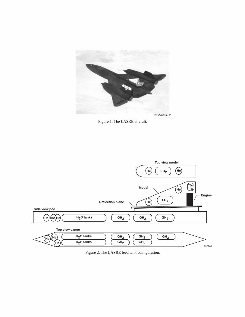
An SR-71 aircraft was modified to carry the aerospike engine and its feed systems. These modifiwere mounted at the rear of the aircraft between the ventrals as shown in figure 1. The Linear Aerospike SR-71 Experiment (LASRE) engine supply systems were enclosed in a pod consistinghydrogen (H2) for the fuel, liquid oxygen (LO2) for the oxidizer, water (H2O) for engine cooling, triethylaluminum-triethylboron (TEA-TEB) for the igniter and helium (He) for purging and tank pressurization (fig 2). Control and monitoring of these systems was accomplished using a singlechannel, aerospike system controller (ASSC).
The basic function of the ASSC is operation of solenoid valves that control the LASRE engine susystems. A subset of the valve layout is shown in figure 3. The ASSC manipulation of these valproduces a firing-flow sequence as shown in figure 4. The start-states (SS) sequence begins withof helium (He) in the LO2 and TEA-TEB lines. A liquid oxygen trickle flow is then commanded to prechill the line, which is followed by an initial water-trickle flow to fill the passages in the engine. main water and liquid oxygen flow starts and then the TEA-TEB igniter begins. The hydrogen linpurged briefly to prevent backflow and finally, the valve is opened. At this point the engine firingbegins and lasts for 3 sec. The cutoff (CO) states begin when the hydrogen and liquid oxygen vaclosed. The water flow stops, and then purges begin to prevent backflow. The autosafe (AS) mwould be initiated next to complete water, liquid oxygen, and hydrogen purges.
The LASRE program was conceived with an aggressive schedule to obtain flight data at minimumDesign considerations for the ASSC were low-cost, man-rated, reliable, fail-safe, with easy to chsoftware, and rapid verification and validation (V and V) capabilities of software. Any first failureneeded to be immediately detected by the system and followed by an automatic abort to a safe configuration. Testing configurations and anomalies frequently required changes to the ASSC software. Software modifications had to be quickly and thoroughly tested to meet schedule constAny aborts needed to be identified in real time for safety of flight decisions and be quickly debugThese challenging requirements led to the three main parts of this paper. First, a description of ASSC fail-safe, single-string, design; second, the automated V and V software testing; and third,real time, intelligent monitoring system used for LASRE system tests. Use of trade names or nammanufacturers in this document does not constitute an official endorsement of such products or manufacturers, either expressed or implied, by the National Aeronautics and Space Administrati
LASRE Control System
The LASRE controller architecture is comprised of four primary components (fig 5). These are thASSC, the allied signal controller (ASC), the pulse code modulator (PCM) data instrumentation syand the cockpit control panel (CCP). The solenoid valves are controlled from the ASSC, which resystem temperature and pressure data from the PCM instrumentation system and operator comfrom the CCP. Command of the main control valves for the water, liquid oxygen, and hydrogen systems is done from the ASC, which receives inputs from the ASSC. Health and status informaalso passed from the controllers and telemetered (TM) to the ground.
Figure 6 shows the LASRE cockpit control panel, which provides the operator with status lights apush buttons for mode control. The firing sequence starts by first pressing the PRESTART and thSTART button. After the firing, the autosafe mode is armed by pressing the ARM/H2 button. From this mode any of the autosafe modes may be selected to dump the hydrogen, water, and liquid osystems.
tional
load ribed in
nd utputs nputs
.
ead in ASC
ata t and
form a . The r each name, an ure 9. e timer he l the
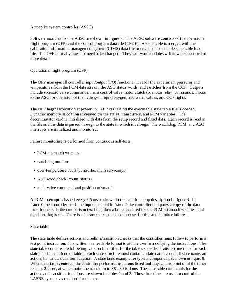
Aerospike system controller (ASSC)
Software modules for the ASSC are shown in figure 7. The ASSC software consists of the operaflight program (OFP) and the control program data file (CPDF). A state table is merged with the calibration information management system (CIMS) data file to create an executable state table file. The OFP normally does not need to be changed. These software modules will now be descmore detail.
Operational flight program (OFP)
The OFP manages all controller input/output (I/O) functions. It reads the experiment pressures atemperatures from the PCM data stream, the ASC status words, and switches from the CCP. Oinclude solenoid valve commands; main control valve motor clutch (or motor relay) commands; ito the ASC for operation of the hydrogen, liquid oxygen, and water valves; and CCP lights.
The OFP begins execution at power up. At initialization the executable state table file is openedDynamic memory allocation is created for the states, transducers, and PCM variables. The decommutator card is initialized with data from the setup record and fixed data. Each record is rthe file and the data is passed through to the state in which it belongs. The watchdog, PCM, andinterrupts are initialized and monitored.
Failure monitoring is performed from continuous self-tests:
• PCM mismatch wrap test
• watchdog monitor
• over-temperature abort (controller, main servoamps)
• ASC word check (count, status)
• main valve command and position mismatch
A PCM interrupt is issued every 2.5 ms as shown in the real time loop description in figure 8. In frame 0 the controller reads the input data and in frame 2 the controller compares a copy of the dfrom frame 0. If the comparison test fails, then a fail is declared for the PCM mismatch wrap testhe abort flag is set. There is a 1-frame persistence counter set for this and all other failures.
State table
The state table defines actions and redline/transition checks that the controller must follow to pertest point instruction. It is written in a readable format to aid the user in modifying the instructionsstate table contains the following: version (identifier for the table), state declarations (functions fostate), and an end (end of table). Each state structure must contain a state name, a default stateactions list, and a transition function. A state table example for typical components is shown in figWhen this state is entered, the controller performs the actions listed and stays at this point until threaches 2.0 sec, at which point the transition to SS1:30 is done. The state table commands for tactions and transition functions are shown in tables 1 and 2. These functions are used to controLASRE systems as required for the test.
for all
strated every points
mber, le is The e
system tem From n to bort path as shown.
mal dlines fault
The t state n is
. It is sts from
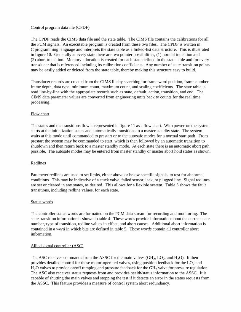
Control program data file (CPDF)
The CPDF reads the CIMS data file and the state table. The CIMS file contains the calibrations the PCM signals. An executable program is created from these two files. The CPDF is written inC programming language and interprets the state table as a linked-list data structure. This is illuin figure 10. Generally at every state there are two pointer possibilities, (1) normal transition and(2) abort transition. Memory allocation is created for each state defined in the state table and fortransducer that is referenced including its calibration coefficients. Any number of state transition may be easily added or deleted from the state table, thereby making this structure easy to build.
Transducer records are created from the CIMS file by searching for frame word position, frame nuframe depth, data type, minimum count, maximum count, and scaling coefficients. The state tabread line-by-line with the appropriate records such as state, default, action, transition, and end. CIMS data parameter values are converted from engineering units back to counts for the real timprocessing.
Flow chart
The states and the transitions flow is represented in figure 11 as a flow chart. With power-on the starts at the initialization states and automatically transitions to a master standby state. The syswaits at this mode until commanded to prestart or to the autosafe modes for a normal start path.prestart the system may be commanded to start, which is then followed by an automatic transitioshutdown and then return back to a master standby mode. At each state there is an automatic apossible. The autosafe modes may be entered from master standby or master abort hold states
Redlines
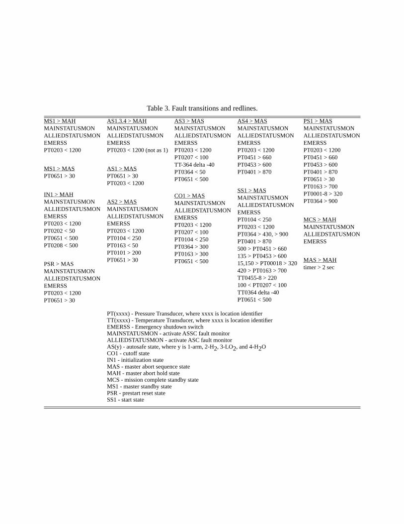
Parameter redlines are used to set limits, either above or below specific signals, to test for abnorconditions. This may be indicative of a stuck valve, failed sensor, leak, or plugged line. Signal reare set or cleared in any states, as desired. This allows for a flexible system. Table 3 shows thetransitions, including redline values, for each state.
Status words
The controller status words are formatted on the PCM data stream for recording and monitoring.state transition information is shown in table 4. These words provide information about the currennumber, type of transition, redline values in effect, and abort causes. Additional abort informatiocontained in a word in which bits are defined in table 5. These words contain all controller abort information.
Allied signal controller (ASC)
The ASC receives commands from the ASSC for the main valves (GH2, LO2, and H2O). It then provides detailed control for these motor-operated valves, using position feedback for the LO2 and H2O valves to provide on/off ramping and pressure feedback for the GH2 valve for pressure regulation. The ASC also receives status requests from and provides health/status information to the ASSCcapable of shutting the main valves and stopping the test if it detects an error in the status requethe ASSC. This feature provides a measure of control system abort redundancy.

ontrol also se data
gram p to
This spike
riate In er
tdown g ors by hown urrent
n the
t to the and card
ce the am
t from
Pulse code modulator (PCM)
The PCM data instrumentation system collects and packages all LASRE data into frames, in a continuously cycling data stream, for telemetry to the ground. This includes experimental data, csystem temperature and pressure data, and ASSC status information. The entire data stream isprovided to the ASSC, which uses control system pressures and temperatures. The timing of theframes also provides external interrupts for the ASSC.
Aerospike Controller Test System Description (ACTS)
The ASSC software was modified and tested using a real time simulation. A simplified block diaof the LASRE controller simulation is shown in figure 12. This test system allowed for closed-lootesting with the controller by driving all the necessary hardware interfaces. A 486 CPU was usedcreate an executable state table from a CIMS signal calibration file and a source state table file. executable file was then downloaded into the ASSC for testing. As part of this simulation an AeroController Test System (ACTS)5 was designed to facilitate V and V testing of the ASSC.
The ACTS allowed inputs to be controlled as a function of the state sequence so that the approptime intervals were maintained to allow the ASSC to proceed through the entire test sequence. addition, simulated failure inputs were provided to verify that the controller would follow the propabort sequences.
Sensor model
The experiment sensors consist of pressure values, temperature values, and an emergency shuswitch voltage. These sensor values are output to the PCM data system through digital-to-analoconverter boards in the Versa Module Eurocard (VME) card cage. Values are set for these sensthe ACTS software that is based on the current state of the controller. This sensor model file is sin table 6. As the state table begins execution sensor redlines are established according to the cstate. The ACTS reads the controller states and sets the appropriate sensor values as defined itable.
Pulse control modulator data system
The PCM data system reads the analog sensor values and generates a PCM bit stream for inpuASSC. The PCM data system also inputs a serial data stream from the ASSC containing healthstatus information. The PCM bit stream is also sent to a PCM decommutator board in the VME cage so that the ACTS program knows the controller state.
Pulse control modulator decommutator board
The PCM bit stream generated by the PCM data system includes the state of the controller. SinACTS program needs to know the controller state in order to set sensor values, this PCM bit stremust be read.
Solenoid valves
There are 19 solenoid valves that are controlled directly by the ASSC. Valve commands are inputhe controller by way of an input discrete board in the VME card cage.

ght o the re used
.5 ms he status
VME r
sed in ce.
ockpit uch d is
me is ler he
ation the that kpit
Allied signal controller (ASC)
The ACTS program normally simulates the ASC. However, there is provision to substitute the flihardware ASC in the simulation if desired. The interface for the ASC includes 4 discrete inputs ttest system through an input discrete board in the VME card cage. Three of the discrete inputs aby the controller to operate three valves (LO2, GH2, and H2O). The remaining discrete is used to request status information. The ASSC status request discrete line is set high for approximately 2to request status. The status request occurs at a 100 Hz rate. The ACTS program responds to trequest within approximately 5–7.5 ms, otherwise a fault bit is set.
Cockpit control panel (CCP)
The CCP signals are interfaced to the controller through output and input discrete boards in the card cage. A simple graphic display was generated to simulate the cockpit panel with the propebuttons, toggle switch, and colored lights. This graphic display was completely functional for thesoftware tester.
Aerospike controller test system software (ACTS)
The ACTS program is written in FORTRAN and ANSI C. The user interface is the same as that uthe standard Dryden flight simulations. This includes a simple command line and display interfa
The real time part consists of two main loops. The primary loop runs at 100 Hz and includes the cpanel input/output, valve/clutch monitoring, and data recording. The secondary loop runs at a mhigher rate (~1000 Hz). This fast loop checks the status request line and the PCM bit stream anresponds with the appropriate action. When the status request line goes high, status informationimmediately sent to the aerospike controller through the serial port. When a new PCM minor frareceived, the controller state is checked as well as the subframe identification (ID). If the controlstate has been changed, the appropriate sensor values are updated based on the state table. Tsubframe ID determines which set of values to output for the multiplexed temperatures.
Manual ASSC testing
The ACTS program was designed to set and monitor the I/O to the ASSC. Verification and validtesting was conducted by starting the ACTS program and then powering up the controller. Both ACTS program and the controller powered up in the first state indicated by the state table. Frompoint, testing was conducted manually, if desired, by pressing the appropriate buttons on the cocpanel to initiate and proceed through the test sequence.
The ACTS program created a time-tagged, log file of the following items during the test:
1) Controller states
2) Transition status
3) Sensor value set (based on state change)
4) Valve/Clutch commanded open/close (on/off)
5) Cockpit buttons change position
6) Cockpit lights turn on/off

inputs uence. 25 psi g a
is test age is
this r limit of
n in 20 psi sage words
ally
ripts own
Automated ASSC Test Results
The ACTS program was designed to read a command file that would control the same simulationas were done manually. This structure allowed for a repeatable, fast, and time-controlled test seqAn example of a script file is shown in table 7. This script sets the pressure signal (PT0001) to 3when the ASSC is executing state number SS1:36. At this moment the state table is commandinpressure range test as shown below.
Setredline PT0001 outside 150 320 goto mas:1 Chamber Pr redline
A timeout parameter (imxtst) and wait state (lwaitst) is set in the script in case the test fails. For tha 60-sec wait time is set. If the state does not go to the MAH:1 within 60 sec, the following messset.
WARNING: Timed out waiting for state: MAH:001
If the signal is outside the range 150 to 320 psi, this test verifies that the setredline command forpressure causes a transition to the specified abort state (mas:1). For this example only the uppe320 only is tested. A portion of the resulting test log file that was generated for this script is showtable 8. When state SS1:36 was entered, the signal PT0001 was set to 325 psi (exceeding the 3limit). Other operations were performed as commanded for this state and finally a transition mes(shown in bold type) was generated. This message was generated by reading the ASSC status described in table 4. Words 1–6 identified the transition signal (PT0001), word 7 identified the code (O - outside), word 8 is not applicable for this cause, word 9 contains the upper limit checked (320 psi is 2078 PCM counts), word 10 has the current value (325 psi is 2110 PCM counts), and finwords 11–14 show the state which the transition occurred (SS1:36).
Hundreds of similar scripts are written to automate the V and V process for the ASSC. These scmay be combined in a single, autotest file and all run at once. An excerpt of an autotest file is shbelow.
# Run the script
macro /home/not/acts/ST_HOTFIRE/VnV/Scripts/Start/start_as01.scr
# Save the logfile
logs /home/not/acts/ST_HOTFIRE/VnV/Logfiles/Start/start_as01.log
# Run the script
macro /home/not/acts/ST_HOTFIRE/VnV/Scripts/Start/start_as02.scr
# Save the logfile
logs /home/not/acts/ST_HOTFIRE/VnV/Logfiles/Start/start_as02.log
# Run the script
macro /home/not/acts/ST_HOTFIRE/VnV/Scripts/Start/start_as03.scr
# Save the logfile
logs /home/not/acts/ST_HOTFIRE/VnV/Logfiles/Start/start_as03.log

line nsitions ed in
ware
e to aid
words indow ent for
ich essor. and the nly 10 own in states is set. he
t he latch
mple the older ly
the ssage e at the h of the
es.
Script files were created to test every normal/abort state transition, all controller functions, all redaborts, and all aborts caused by the ASSC and ASC monitors. Refer to figure 11 for the state traand table 3 for the fault transitions and redline conditions. The status words themselves describtables 4 and 5 were tested for correct status. As a result of this software testing automation, an exhaustive set of test cases were quickly executed and easily analyzed. The time to qualify softchanges to support LASRE testing was significantly shortened.
Mission Control Center Real Time Monitoring Results
Intelligent monitoring systems have been developed for flight programs such as the space shuttlin identifying problems in real time.6 The LASRE program had a similar requirement to monitor andprocess the ASSC status words (tables 4 and 5) in real time so that any abort condition would beimmediately known. Therefore, an automated, real time analysis tool was used to filter the statusbased on events as textual strings and numerical values and output this information onto an X-wmessage stack. This tool was developed in-house at NASA Dryden and is called signal managemanalysis in real time (SMART). The rule-based, intelligent real time monitor7 was used for all ground and flight tests in the mission control center (MCC).
Real time FORTRAN (RTF) processing
The PCM real time data processing is shown in a top-level data flow in figure 13. Signals are telemetered at their frame rate. This is 100hz for the ASSC. The data enters a receiver rack, whsends it out to a telemetry and radar acquisition processing system (TRAPS), and front-end procThe data is converted into engineering units in a real time FORTRAN (RTF) processor at 100 Hzthen sent out on an Ethernet data server. This server sends the data to the Unix workstations inMCC at about 15hz. Unfortunately, this is too slow to read the abort status words that exist for oms. In order to catch the abort status words, latching logic was programmed into the RTF as shfigure 14. The ASSC status words are read at 100hz and if there are no aborts several previousare saved in a ring buffer. When an abort flag is set, the ring buffer stops updating and a latch flagThese buffered signals contain the abort cause and are sent out through the Ethernet server to tSMART application. The SMART decodes these raw buffered words into messages defining the aborreason. When the abort flag is reset, the ring buffer begins updating the status words again and tflag is reset.
SMART message stack
The SMART monitor application was used in the MCC to display the LASRE abort codes. An exaof the message stack is shown in figure 15. New messages are added to the stack at the top andmessages are pushed down. As messages are cleared off the stack, the messages automaticalcompress, thus filling in the gap between messages.
The example shown in the figure is from an ASSC abort. The cause was determined by readingstatus words defined in table 4 from the latched ring buffer and converting this information to a mestring. In this case the pressure signal (PT0651) exceeded a redline limit of 30 psi. The pressurtime of the abort was 33 psi and the ASSC was in the state as 2:11. Other information about eacmain control valves is also shown.
SMART log file
The SMART message window also had an option to save all the messages that are both set andrescinded to a log file. Included in the SMART knowledge base were rules for the state messag

an out uted and ay for
n in t server he
d
lexible by
lth, and
nals
lso
dded, t easy nerate
nd ery
r. oved ords
sts. In the
iringd their
After the test was completed, the SMART log file was saved and Unix commands were run to scthe state messages. This was done to get a quick and rough estimate of which states were exectheir times. The flight data access system (FDAS) states and times had to be run the following dexact states and times from a batch file. A comparison of the FDAS and SMART states is showtable 9. The SMART missed some of the states because of the slow sample rate of the Etherneand the SMART architecture that writes to a file on the hard disk while still running in real time. Ttimes were comparable, however, for a quick and gross check. This log of the state times proveinvaluable for determining event times for batch data analysis and plotting.
Conclusion
The aerospike system controller (ASSC) had challenging requirements to be fail-safe, low cost, fto software changes, and a quick V and V software turnaround. These conditions were satisfiedusing a clever architecture and through the use of auto-testing tools.
The ASSC was fail safe because of the conservative approach in actively monitoring status, heasensor redlines. Any failure in the system would automatically transition to an orderly and safe shutdown sequence
Using a simplex signal set from the pulse code modulator (PCM) rather than dedicated ASSC sighad never been done at NASA Dryden. This approach resulted in a significant cost reduction. Calibrations for PCM signals became an input file for the ASSC software. The operational flight program (OFP) interrupts were slaved to the PCM frames. The ASSC was single string, which areduced the cost.
Software changes were easy to make because of the link-list structure. States could easily be adeleted, or modified in the state table file. The control program data file (CPDF) software made ito change the calibration information management system (CIMS) and state table input files to gea new executable ASSC program.
The aerospike controller test system simulation provided a test tool to automate the verification avalidation runs. Exhaustive script files were run from a single master file to automatically test evpath and abort. The log files provided an archive record of the test results.
Status words from the ASSC provided excellent insight to ascertain the condition of the controlleThese words contained states, abort codes, transitions, and input/output discretes. This data prinvaluable in providing information about the controller to debug and assess problems. Status wwere automatically decoded in real time using the signal management for analysis in real time (SMART) application in the MCC during all testing of the LASRE. Immediate analysis of any controller problem was demonstrated and proved to be a great help in conducting the LASRE teaddition, the automated time-tagged states that were generated from SMART in real time duringtesting were a tremendous help in identifying event times for further off line analysis.
References
1 Angelino, Giafranco, “Approximate Method for Plug Nozzle Design,” AIAA Journal, vol 2, no. 10, Oct. 1975,pp. 1834-1835.
2 Rockwell International Corporation, “Advanced Aerodynamic Spike Configurations: Volume 2–Hot FInvestigations,” AFRPL-TR-67-246, Sept. 1967. (Distribution authorized to U.S. Government agencies ancontractors; other requests shall be referred to WL/FIMS Wright-Patterson AFB, Ohio 45433–6503.)

E-72-
rd S.
nt
ems
3 Mueller, T. J. and W. P. Sule, “Basic Flow Characteristics of a Linear Aerospike Nozzle Segment,” ASMWA/Aero-2, Nov. 1972.
4 Corda, Stephen, Bradford A. Neal, Timothy R. Moes, Timothy H. Cox, Richard C. Monaghan, LeonaVoelker, Griffin P. Corpening, and Richard R. Larson, Flight Testing the Linear Aeropike SR-71 Experime(LASRE), NASA TM-1998-206567, Sept 1998.
5 Kellogg, Gary V., and Ken A. Norlin, “Aerospike Controller Test System,” NASA Tech Briefs, vol. 21 No.2, Feb1997, pp.28–30.
6 Land, Sherry A., Jane T. Matlin, Carrol Thronesberry, Debra L. Schreckenghost, Making Intelligent SystemsTeam Players, A Guide to Developing Intelligent Monitoring Systems, NASA TM 104807, July 1995.
7 Larson, Richard, and D. Edward Millard, A Rule-Based System for Real-Time Analysis of Control Syst,NASA TM 104258, Oct 1992.

Table 1. State table actions functions.
Function Description
ON <light discrete> OFF
Set cockpit control lights
OPEN <solenoid valve>CLOSE
Command to open/close solenoid valves
RESET TIMER Reset state table timer
ACTIVATE <clutch>DEACTIVATE
Engage main valve clutches/relays
SETDEF<MAINSTATUSMON><ALLIEDSTATUSMON>
Starts health monitoring of specified processor
SETREDLINEABOVE, BELOW,OUTSIDE<pressure signal>goto<state>
The function transitions to the goto state when the pressure signal is outside the specified limits
SETREG<pressure signal><lolim><hilim><solenoidvalve>
The pressure is regulated from the upper limit to the lower limit by opening the specified valve
CLEARREG Clears regulator function
SETPRES<pressuresignal><lolim><hilim><solenoid valve>
The pressure is regulated from the lower limit to the upper limit by opening the specified valve
CLEARPRESS Clears pressure regulator function
CLEARABORT Resets any abort flags

Table 2. State table transition functions.
Function Description
TIMER wait <time> goto<state>
Transition to specified state after wait time (since last reset time function)
<pressure signal> ABOVE<value><goto><state>
Transition to specified state if specified pressure is above the value
<pressure signal> BELOW<value><goto><state>
Transition to specified state if specified pressure is below the value
ON goto <state> Transition to specified state if the input discrete is true
OFF goto <state> Transition to specified state if the input discrete is false
SAVE <signal> The function saved the specified signal to be used in conjunction with the DELTA command
<signal> DELTA min<limit> goto <state>
Transition to specified state if the delta change from the SAVE command is not less than the limit test
MMAEP
MP
INMAEPPPP
PMAEPP
Table 3. Fault transitions and redlines.
S1 > MAHAINSTATUSMONLLIEDSTATUSMONMERSST0203 < 1200
S1 > MAST0651 > 30
1 > MAHAINSTATUSMONLLIEDSTATUSMONMERSST0203 < 1200T0202 < 50T0651 < 500T0208 < 500
SR > MASAINSTATUSMONLLIEDSTATUSMONMERSST0203 < 1200T0651 > 30
AS1.3.4 > MAHMAINSTATUSMONALLIEDSTATUSMONEMERSSPT0203 < 1200 (not as 1)
AS1 > MASPT0651 > 30PT0203 < 1200
AS2 > MASMAINSTATUSMONALLIEDSTATUSMONEMERSSPT0203 < 1200PT0104 < 250PT0163 < 50PT0101 > 200PT0651 > 30
AS3 > MASMAINSTATUSMONALLIEDSTATUSMONEMERSSPT0203 < 1200PT0207 < 100TT-364 delta -40PT0364 < 50PT0651 < 500
CO1 > MASMAINSTATUSMONALLIEDSTATUSMONEMERSSPT0203 < 1200PT0207 < 100PT0104 < 250PT0364 > 300PT0163 > 300PT0651 < 500
AS4 > MASMAINSTATUSMONALLIEDSTATUSMONEMERSSPT0203 < 1200PT0451 > 660PT0453 > 600PT0401 > 870
SS1 > MASMAINSTATUSMONALLIEDSTATUSMONEMERSSPT0104 < 250PT0203 < 1200PT0364 > 430, > 900PT0401 > 870500 > PT0451 > 660135 > PT0453 > 60015,150 > PT00018 > 320420 > PT0163 > 700TT0455-8 > 220100 < PT0207 < 100TT0364 delta -40PT0651 < 500
PS1 > MASMAINSTATUSMONALLIEDSTATUSMONEMERSSPT0203 < 1200PT0451 > 660PT0453 > 600PT0401 > 870PT0651 > 30PT0163 > 700PT0001-8 > 320PT0364 > 900
MCS > MAHMAINSTATUSMONALLIEDSTATUSMONEMERSS
MAS > MAHtimer > 2 sec
PT(xxxx) - Pressure Transducer, where xxxx is location identifierTT(xxxx) - Temperature Transducer, where xxxx is location identifierEMERSS - Emergency shutdown switchMAINSTATUSMON - activate ASSC fault monitorALLIEDSTATUSMON - activate ASC fault monitor AS(y) - autosafe state, where y is 1-arm, 2-H2, 3-LO2, and 4-H2OCO1 - cutoff stateIN1 - initialization stateMAS - master abort sequence stateMAH - master abort hold stateMCS - mission complete standby stateMS1 - master standby statePSR - prestart reset stateSS1 - start state

n
an
tes
an
s and
Table 4. ASSC transition words.
Transition Word Description
1–6 Six-character name of item causing transition‘defaul’(t) - default transition‘TIMER’ - table timer‘ALLMON’ - ASC abort‘MANMON’ - ASSC abort‘PTxxxx’ - name of pressure transducer identified by xxxx causing transition‘TTxxxx’ - name of temperature tranducer identified by xxxx causing transitio
7 Transition condition code‘a’ - above‘b’ - below‘c’ - change (delta)‘d’ - default‘f’ - off‘h’ - main controller over temp of 120 °C‘m’ - ASC data mismatch‘n’ - on‘o’ - ‘outside‘p’ - ASSC PMC mismatch‘r’ - ASC not receiving ASSC status‘s’ - no data saved for delta function‘t’ - ASC servoamp temperature over limit (40 °C)‘w’ - wait (timer expires on a wait); refers to a watch dog monitor fail (if MANMON is set)‘z’ - ASC data word count error
8 Lower limit checked for transition if applicable, otherwise 0. If the transition is‘h’, the word contains the ASSC temperature limit.
9 Upper limit checked for transition if applicable, otherwise 0. If the transition condition is a ‘t’ (ASC servoamp temperature over limit), then this word indicawhich servoamp is over limit.‘1’ GH2 Servoamp‘2’ LO 2 Servoamp‘3’ H 2O Servoamp
10 Current value is the transition item, otherwise 0. If the transition condition is ‘h’, then this word contains the ASSC temperature.
11–14 State in which the transition occurred. These words contain three characterone number.
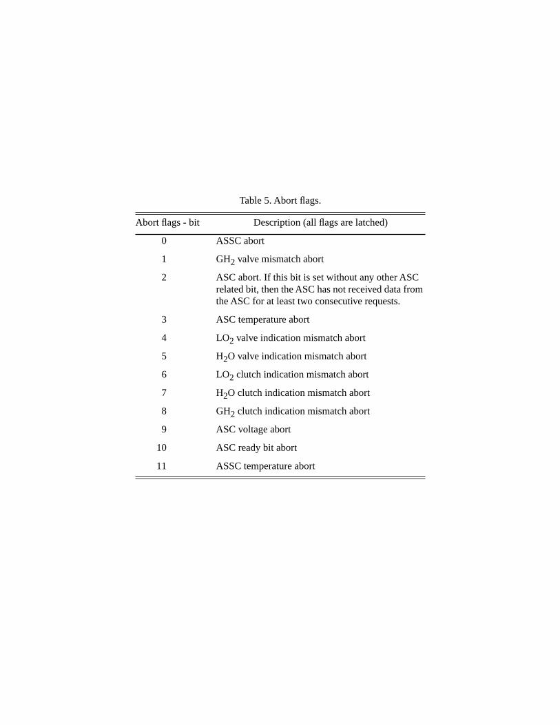
Table 5. Abort flags.
Abort flags - bit Description (all flags are latched)
0 ASSC abort
1 GH2 valve mismatch abort
2 ASC abort. If this bit is set without any other ASC related bit, then the ASC has not received data from the ASC for at least two consecutive requests.
3 ASC temperature abort
4 LO2 valve indication mismatch abort
5 H2O valve indication mismatch abort
6 LO2 clutch indication mismatch abort
7 H2O clutch indication mismatch abort
8 GH2 clutch indication mismatch abort
9 ASC voltage abort
10 ASC ready bit abort
11 ASSC temperature abort

Table 6. Sensor model of start states.
State Signal State Signal
SS1:2 PT0651 = 600.0 SS1:18 PT0401 = 700.0
SS1:4 PT0651 = 15.0 SS1:20 PT0451 = PT0453 =
580.0500.0
SS1:5 PT0651 = 600.0 SS1:21 PT0104 = 300.0
SS1:8 PT0208 = PT0651 = PT0207 =
720.0600.0200.0
SS1:23 PT0104 = 15.0
SS1:9 PT0651 = 600.0 SS1:24 PT0104 = 300.0
SS1:10 PT0207 = 15.0 SS1:28 PT0401 = 777.0
SS1:11 PT0207 = 200.0 SS1:30 PT0651 = 30.0
SS1:13 TT0364 = 70.0 SS1:33 PT0001 = PT0002 = PT0003 = PT0004 = PT0005 = PT0006 = PT0007 = PT0008 = TT0455 = TT0456 = TT0457 = TT0458 =
220.0220.0220.0220.0220.0220.0220.0220.0170.0170.0170.0170.0
SS1:14 PT0207 = 15.0 SS1:35 PT0104 = PT0164 =
300.0500.0
SS1:16 TT0364 = PT0210 =
–200.01313.0
SS1:36 PT0104 = PT0210 =
15.01313.0

Table 7. Script file.
# Test redline on PT0001 high (320) in ss1:37
logc
file
do /home/not/acts/ST_HOTFIRE/VnV/Scripts/Start/initsensor
do /home/not/acts/ST_HOTFIRE/VnV/Scripts/Start/prestartinit.scr
# Set test values
mdl
state=SS1:36
PT0001=325
# Select TEA-TEB canister #1
cp
TEATEBSEL=1
# Press the start button
START=1; START=0
# Wait for state MAH:1 (Master Abort Hold)
mdl
imxtst=6000; - Timeout = 60 seconds
waitst=MAH:1; - Set wait state to master abort hold
val
lwaitst=1; - Wait for master abort hold state
# Controller should now be in state MAH:001
prst
# Controller should now be in state MAH:001
# Validation/Verification checks for this test script:
# system goes to MAS in SS1:37? _______
# abort is due to redline of PT0001 above 320? _______
#
# Date:___________________ Initials:___________________
file
do /home/not/acts/ST_HOTFIRE/VnV/Scripts/Start/msinit
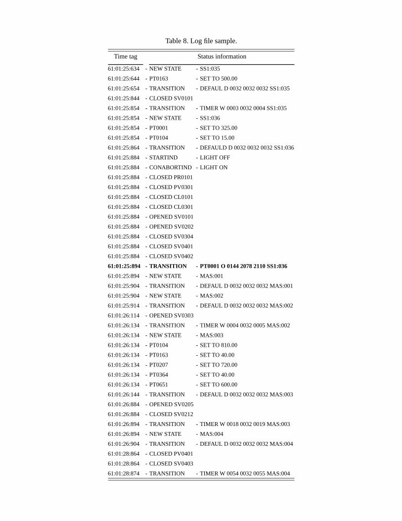
Table 8. Log file sample.
Time tag Status information
61:01:25:634 - NEW STATE - SS1:035
61:01:25:644 - PT0163 - SET TO 500.00
61:01:25:654 - TRANSITION - DEFAUL D 0032 0032 0032 SS1:035
61:01:25:844 - CLOSED SV0101
61:01:25:854 - TRANSITION - TIMER W 0003 0032 0004 SS1:035
61:01:25:854 - NEW STATE - SS1:036
61:01:25:854 - PT0001 - SET TO 325.00
61:01:25:854 - PT0104 - SET TO 15.00
61:01:25:864 - TRANSITION - DEFAULD D 0032 0032 0032 SS1:036
61:01:25:884 - STARTIND - LIGHT OFF
61:01:25:884 - CONABORTIND - LIGHT ON
61:01:25:884 - CLOSED PR0101
61:01:25:884 - CLOSED PV0301
61:01:25:884 - CLOSED CL0101
61:01:25:884 - CLOSED CL0301
61:01:25:884 - OPENED SV0101
61:01:25:884 - OPENED SV0202
61:01:25:884 - CLOSED SV0304
61:01:25:884 - CLOSED SV0401
61:01:25:884 - CLOSED SV0402
61:01:25:894 - TRANSITION - PT0001 O 0144 2078 2110 SS1:036
61:01:25:894 - NEW STATE - MAS:001
61:01:25:904 - TRANSITION - DEFAUL D 0032 0032 0032 MAS:001
61:01:25:904 - NEW STATE - MAS:002
61:01:25:914 - TRANSITION - DEFAUL D 0032 0032 0032 MAS:002
61:01:26:114 - OPENED SV0303
61:01:26:134 - TRANSITION - TIMER W 0004 0032 0005 MAS:002
61:01:26:134 - NEW STATE - MAS:003
61:01:26:134 - PT0104 - SET TO 810.00
61:01:26:134 - PT0163 - SET TO 40.00
61:01:26:134 - PT0207 - SET TO 720.00
61:01:26:134 - PT0364 - SET TO 40.00
61:01:26:134 - PT0651 - SET TO 600.00
61:01:26:144 - TRANSITION - DEFAUL D 0032 0032 0032 MAS:003
61:01:26:884 - OPENED SV0205
61:01:26:884 - CLOSED SV0212
61:01:26:894 - TRANSITION - TIMER W 0018 0032 0019 MAS:003
61:01:26:894 - NEW STATE - MAS:004
61:01:26:904 - TRANSITION - DEFAUL D 0032 0032 0032 MAS:004
61:01:28:864 - CLOSED PV0401
61:01:28:864 - CLOSED SV0403
61:01:28:874 - TRANSITION - TIMER W 0054 0032 0055 MAS:004

Table 9. State time comparisons.
FDAS times SMART times State
09.19.53.290 SS1:1
09.19.53.300 09:19:53.300 SS1:2
09.19.53.480 SS1:3
09.19.53.490 09:19:53.499 SS1:7
09.19.53.760 09:19:53.765 SS1:8
09.19.53.870 09:19:53.863 SS1:9
09.19.53.880 09:19:54.756 SS1:13
09.19.54.740 09:19:56.008 SS1:14
09.19.55.790 SS1:15
09.19.55.800 09:19:59.871 SS1:16
09.19.59.740 09:19:59.740 SS1:17
09.19.59.750 09:20:00.567 SS1:18
09.20.00.520 09:20:00.533 SS1:19
09.20.02.270 09:20:02.284 SS1:20
09.20.02.550 09:20:02.680 SS1:21
09.20.02.650 SS1:22
09.20.02.660 09:20:02.946 SS1:26
09.20.02.820 09:20:03.472 SS1:27
09.20.03.310 09:20:04.004 SS1:28
09.20.03.800 09:20:04.530 SS1:29
09.20.04.310 SS1:30
09.20.04.320 SS1:31
09.20.04.330 09:20:04.793 SS1:33
09.20.04.630 09:20:04.793 SS1:34
09.20.04.690 09:20:05.027 SS1:35
09.20.04.910 09:20:05.357 SS1:36
09.20.05.240 SS1:37
09.20.05.250 09:20:05.800 SS1:38
EC97-44295-108
Figure 1. The LASRE aircraft.
Figure 2. The LASRE feed tank configuration.
H2O tanks GH2
GH2GH2
GH2GH2
GH2
GH2 GH2
LO2
Top view model
Side view pod
Top view canoe
He
He
He HeLO2
He He
He
H2O tanks
H2O tanks
He He He
Reflection plane
Engine
990261
ModelTEA-TEB

Figure 3. LASRE supply systems valve arrangement.
Figure 4. LASRE engine firing sequence.
990262
H2
H2O H2O
He
Hepurge
He
4 lines
4 lines80
80
20
20
100
100
4 lines
Thrusters 1-4
Thrusters 5-8
LO2He
He
Solenoid valveVenturi, percent
Hepurge
4 lines
4 lines
TE
A-T
EB
TE
A-T
EB
Fluid flowPurges
Trickle
*TEA-TEB trickle purge provided continuously
Provides GHe purge after TEA-TEB depletion
Main
Trickle
CO ASSSSupply
systems
H2O
LO2
TEA-TEB*
GH2
Ignition
990263

Figure 5. LASRE controller architecture.
Figure 6. SR-71 Aft cockpit control panel.
Data stream(TM to ground)
Data
990264
Control
Control
Control
Health/status
Health/status
Data stream
Instrumentation system
Main valves Solenoid valves
Allied signalcontroller
(ASC)
Maincontroller
(ASSC)
Cockpitcontrol panel
(CCP)
PCM datainstrumentation
system
CONTROLLER ABORT STANDBY
PRESTART
Aft cockpit control panel
PUMP PRESSLOW
MIST PRESSLOW
N2 PURGELOW
START AUTOSAFE
ARM/H2
H2O
LO2
POWER
TEA-TEB
SELECT
LAMPTEST
990265
ON
ON
WATER PUMPS WATER MIST N2 PURGE
OFF
ON
OFF
ON
OFF
2 1
POWER
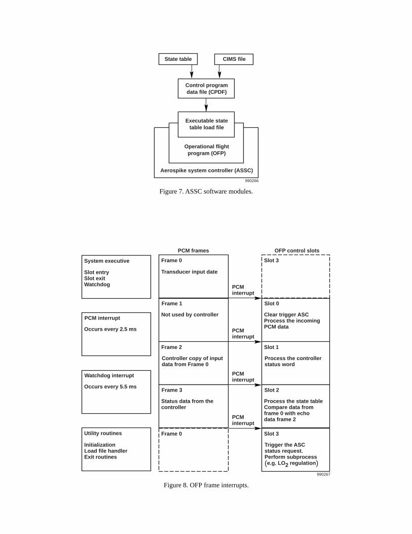
Figure 7. ASSC software modules.
Figure 8. OFP frame interrupts.
Control programdata file (CPDF)
Executable statetable load file
Operational flightprogram (OFP)
Aerospike system controller (ASSC)
State table CIMS file
990266
Slot 2
Process the state tableCompare data fromframe 0 with echodata frame 2
Slot 3
990267
Trigger the ASCstatus request.Perform subprocess(e.g. LO2 regulation)
InitializationLoad file handlerExit routines
Slot 0
Clear trigger ASCProcess the incomingPCM data
Slot 1
Process the controllerstatus word
Slot 3
PCMinterrupt
OFP control slots
Frame 3
Status data from thecontroller
Frame 0
Frame 1
Not used by controller
Transducer input date
Frame 2
Controller copy of inputdata from Frame 0
Frame 0
PCM frames
Watchdog interrupt
Occurs every 5.5 ms
Utility routines
PCM interrupt
Occurs every 2.5 ms
Slot entrySlot exitWatchdog
System executive
PCMinterrupt
PCMinterrupt
PCMinterrupt
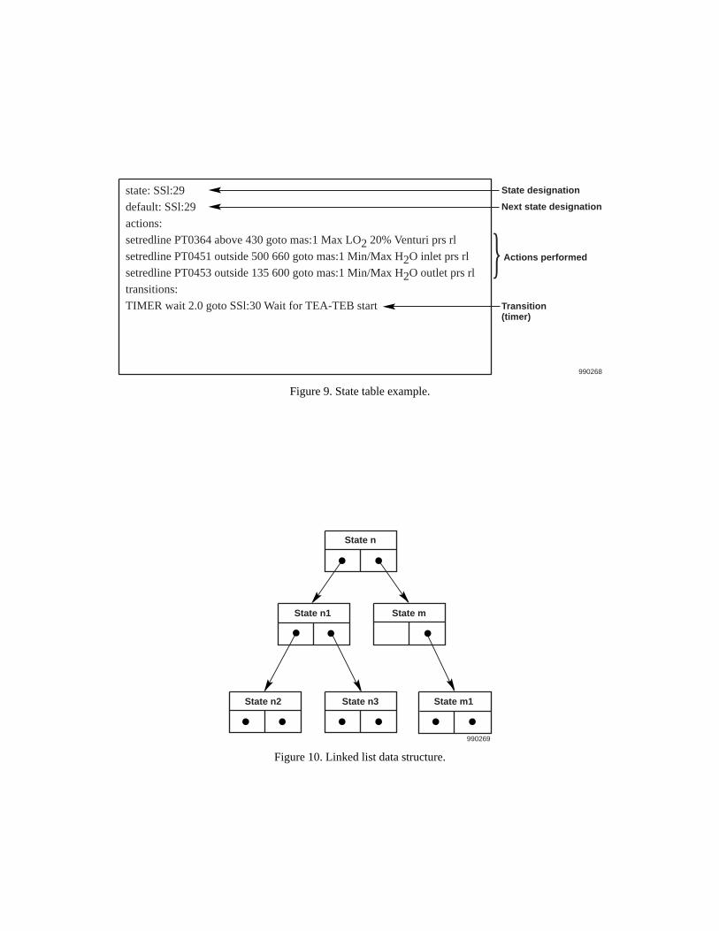
Figure 9. State table example.
Figure 10. Linked list data structure.
state: SSl:29
default: SSl:29
actions:
setredline PT0364 above 430 goto mas:1 Max LO2 20% Venturi prs rl
setredline PT0451 outside 500 660 goto mas:1 Min/Max H2O inlet prs rl
setredline PT0453 outside 135 600 goto mas:1 Min/Max H2O outlet prs rl
transitions:
TIMER wait 2.0 goto SSl:30 Wait for TEA-TEB start
State designation
Next state designation
Actions performed
Transition(timer)
990268
}
State n
State n1 State m
State n3 State m1
990269
State n2

Figure 11. ASSC state transition overview.
Figure 12. Aerospike controller test system.
Masterstandby
Prestartbutton
Power on
Automatictransition
Automatictransition
Normal transitionAbort path
Startbutton
Automatictransition
Start
Masterabort
sequence
Prestart Shutdown
Initialize
Prestartreset
Autosafemodes
Autosafebutton Autosafe
button
Prestartbutton
Masteraborthold
990270
Missioncompletestandby
Statetable
486 CPU
CIMS file
PCM data system
ASSC hardware
Hardware models
VME– Analog/discrete I/O– Serial port– Decomm board
990271
Software modelsASC model
State table
Sensor modelCIMS file

Figure 13. Ground station PCM data flow.
Figure 14. RTF abort latch logic.
TM
100 Hz
Receiver
TRAPSGroundstation
100 Hz
Front end
RTF
990272
Real timeethernet server
15 Hz
MCC real timedisplay
applications
TM
Abortflag
Read ASSC status words
Yes
RTF
990273
Update delayedstatus words
Stop delayedstatus words
update
Set latchedflag
No
Resetlatched flag
Ethernetdata server

Figure 15. SMART message stack.
10:59:53.689 ABORT last main valve temp; H2= 17C; LO2= 18C; H2O = 19C10:59:53.689 ABORT actual mn valve curr; H2= 3.4 amp; LO2= –0.2 amp; H2O= –0.2 amp10:59:53.689 ABORT cmded mn valve curr; H2= –3.3 amp; LO2= 0.0 amp; H2O= 0.0 amp10:59:53.689 ABORT last main valve posn; H2= 0.22 in; LO2= 0 deg; H2O= 0 deg10:59:53.753 ABORT latch last 5; as2:11 as 2:11 as 2:11 as 2:11 as 2:1110:59:53.753 ABORT latch @ as 2:11; PT0651; val= 101 ABOVE limit 9210:59:53.753 ABORT eu; PT0651; curval= 33; hilim= 30
Message stack field
Time of day
Message counter
SMART Messages
Menu Hold Latch
Resize window
Comment field
Scroll bar
990274
10:59:54.216 542
REPORT DOCUMENTATION PAGE Form ApprovedOMB No. 0704-0188
Public reporting burden for this collection of information is estimated to average 1 hour per response, including the time for reviewing instructions, searching existing data sources, gathering andmaintaining the data needed, and completing and reviewing the collection of information. Send comments regarding this burden estimate or any other aspect of this collection of information,including suggestions for reducing this burden, to Washington Headquarters Services, Directorate for Information Operations and Reports, 1215 Jefferson Davis Highway, Suite 1204, Arlington,VA 22202-4302, and to the Office of Management and Budget, Paperwork Reduction Project (0704-0188), Washington, DC 20503.
1. AGENCY USE ONLY (Leave blank) 2. REPORT DATE 3. REPORT TYPE AND DATES COVERED
4. TITLE AND SUBTITLE 5. FUNDING NUMBERS
6. AUTHOR(S)
8. PERFORMING ORGANIZATION REPORT NUMBER
7. PERFORMING ORGANIZATION NAME(S) AND ADDRESS(ES)
9. SPONSORING/MONITORING AGENCY NAME(S) AND ADDRESS(ES) 10. SPONSORING/MONITORING AGENCY REPORT NUMBER
11. SUPPLEMENTARY NOTES
12a. DISTRIBUTION/AVAILABILITY STATEMENT 12b. DISTRIBUTION CODE
13. ABSTRACT (Maximum 200 words)
14. SUBJECT TERMS 15. NUMBER OF PAGES
16. PRICE CODE
17. SECURITY CLASSIFICATION OF REPORT
18. SECURITY CLASSIFICATION OF THIS PAGE
19. SECURITY CLASSIFICATION OF ABSTRACT
20. LIMITATION OF ABSTRACT
NSN 7540-01-280-5500 Standard Form 298 (Rev. 2-89)Prescribed by ANSI Std. Z39-18298-102
Automated Testing Experience of the Linear AerospikeSR-71 Experiment (LASRE) Controller
WU 242-33-02-00-23-00-T15
Richard R. Larson
NASA Dryden Flight Research CenterP.O. Box 273Edwards, California 93523-0273
H-2380
National Aeronautics and Space AdministrationWashington, DC 20546-0001 NASA/TM-1999-206588
System controllers must be fail-safe, low cost, flexible to software changes, able to output health and statuswords, and permit rapid retest qualification. The system controller designed and tested for the aerospike engineprogram was an attempt to meet these requirements. This paper describes (1) the aerospike controller design,(2) the automated simulation testing techniques, and (3) the real time monitoring data visualization structure.Controller cost was minimized by design of a single-string system that used an off-the-shelf 486 centralprocessing unit (CPU). A linked-list architecture, with states (nodes) defined in a user-friendly state table,accomplished software changes to the controller. Proven to be fail-safe, this system reported the abort causeand automatically reverted to a safe condition for any first failure. A real time simulation and test systemautomated the software checkout and retest requirements. A program requirement to decode all abort causes inreal time during all ground and flight tests assured the safety of flight decisions and the proper execution ofmission rules. The design also included health and status words, and provided a real time analysisinterpretation for all health and status data.
Aerospike engine, Automated software testing, Controller architecture, LASRE,Real time analysis, SR-71 experiment
A03
34
Unclassified Unclassified Unclassified Unlimited
September 1999 Technical Memorandum
Presented at the ITEA Test and Evaluation in the Information Age Symposium, September 21–24, 1999,Atlanta, Georgia, at a poster session.
Unclassified—UnlimitedSubject Categories 05, 61, 62