automated production of mcb report (repaired) (1)
TRANSCRIPT

1 | P a g e
Summer Internship Report On
AUTOMATED PRODUCTION OF MCB
In HAVELLS INDIA LTD.
BADDI, HIMACHAL PRADESH, INDIA
Submitted By:-
Ankit Kumar (R790209014)
Namit Mehta (R790209033)
Puneet Dobhal (R790209045)
Rohit Joshi (R790209048)
In Fulfillment of
7TH
Semester, B.Tech (Electronics Engineering)
Under the Guidance of
Ms. Nisha Kumari
Graduate Engineer Trainee (Havells India Ltd.)
University of Petroleum & Energy Studies
College of Engineering Studies, Energy Acres
Bidholi, Dehradun

2 | P a g e
Acknowledgement
The project bears the imprints of the efforts extended by many people to whom we are deeply
indebted.
The eight weeks of working on this project under the guidance of our Project Leader has
greatly influenced our way of thinking towards facing the challenges during day-to-
day development of this project. This will help us a lot in future as we move further ahead in our
professional lives in the days to come.
We would like to thank our mentor Ms. Nisha Kumari under whose able guidance we gained
the insights and ideas without which the project could not have seen the light of the day. Her
suggestions have been valuable and her teachings during the course of our discussions would
continue to be a guiding principle in our works in the future as well.
We would like to thank the University of Petroleum & Energy Studies and Havells India Ltd.
for providing us an opportunity to apply our technical knowledge in the form of this project.
Last but not the least we would also like to express my gratitude to Havells employees who
helped us a lot throughout this project.

3 | P a g e
College of Engineering
University of Petroleum and Energy Studies
Dehradun
CERTIFICATE
This is to certify that the project work on “Automated Production Of MCB” submitted to the
University of Petroleum and Energy Studies, Dehradun, by Ankit Kumar(R790209014), Namit
Mehta(R790209033), Rohit Joshi(R790209048), Puneet Dobhal(R790209045) a Summer
internship project in Electronics Engineering Academic session 2012-13 is a bonafide work
carried out by them under my supervision and guidance.
-------------------------------------
Date: 27/07/2012 Ms. Nisha Kumari
Graduate Engineer Trainee (Havells India Ltd.)

4 | P a g e
CONTENTS:-
1. INTRODUCTION TO COMPANY 7
2. INTRODUCTION TO PROJECT 10
3. TECHNICAL SPECIFICATIONS 16
4. SPOT WELDING 17
5. KNOB ASSEMBLY 27
6. MCB ASSEMBLY 31
7. CONSTRUCTION & OPERATION OF MCB 35
8. CHARACTERISTICS CURVES & TRIPPING CHARACTERISTICS 37
9. DC APPLICATIONS 41

5 | P a g e
10. SENSORS USED IN MCB AUTOMATION 42
11. MCB TESTING AND VERIFICATION 45
12. TESTING SOLUTION FOR MCB 48
13. SELECTION OF MCB 59
14. TYPES OF MCB 61
15. ERRORS AND CORRECTIONS 63
16. REFERENCES 64

6 | P a g e
LIST OF FIGURES & PICTURES
1. STEPS OF SPOT WELDING 20
2. PICTURES OF SPOT WELDING 21
3. PROCESS FLOW DIAGRAM OF SPOT WELDING 25
4. BIMETALS 26
5. KNOB ASSEMBLY 27
6. PROCESS FLOW DIAGRAM OF KNOB ASSEMBLLY 29
7. PICTURES OF KNOB ASSEMBLY 30
8. MCB ASSEMBLY BLOCK DIAGRAM 32
9. INTERNAL VIEW OF MCB 34
10. TRIPPING CURVES 38
11. CURRENT LIMITING CURVE 39
12. HAMMER TRIPPING 39
13. TEST BENCH 50

7 | P a g e
1. INTRODUCTION TO COMPANY:-
1.1. PROFILE:-
Starting off as an electrical trading company in 1958, Havells India Ltd. today is an emerging
leader and an end-to-end solution provider in the Power Distribution Equipment industry. The
company catering to the needs of domestic and industrial market has seven manufacturing units
in India. Havells India Ltd, a billion-dollar-plus organization, and one of the largest & India's
fastest growing electrical and power distribution equipment company, manufacturing products
ranging from Building Circuit Protection, Industrial & Domestic Switchgear, Cables& Wires,
Energy Meters, Fans, CFL Lamps, Luminaries for Domestic, Commercial& Industrial
application and Modular Switches. Havells owns some of the prestigious global brands like
Crabtree*, Sylvania, Concord, Luminance, Claude, Sylvania, Linolite, SLI Lighting & Zenith.
Havells reach stretches across 91 branch offices, over 2000 authorized dealers and thousands of
approved retail outlets. The company has an enviable clientele, not only in the domestic market,
but also in international markets like UK, Malaysia, Singapore, Bangladesh, Sri Lanka, Dubai,
Africa, Iran and Iraq. The company is currently exporting to over 50 countries globally. Havells
is acknowledged as a manufacturer & supplier of the widest range of quality low voltage
electrical equipment. With a number of strategic alliances in place, Havells is the only company
that has shown phenomenal growth rate with the help of various joint ventures, acquisitions,
mergers and takeovers. Havells recently acquired Frankfurt headquartered, SLI Sylvania for $
300 mn. The company is a leading global designer and provider of lighting systems for lamps
and fixtures. Sylvania is one of the most globally recognized brands for over a century in the
electrical industry with brands like Sylvania, Concord: marlin, Lumiance, Marlin, Claude and
Linolite-Sylvania.

8 | P a g e
1.2. PROMOTERS:-
QRG Group is one of the fastest growing Electrical and Power Distribution Equipment Company
in the country, manufacturing products ranging from building circuit protection, industrial &
domestic switchgear, cables & wires, energy meters, fans, CFLs, luminaries, bath fittings and
modular switches. The group comprises of 5 companies –
1) Havells India Ltd. (the flagship company)
2) Standard Electricals
3) Crabtree India Ltd
4) TTL
5) Sylvania
With 13 state of the art manufacturing plants, 24 branch offices and a strong backing of over
3000 professionals across India the group has achieved rapid success in the past few years. The
group has recorded a turnover of Rs. 963 crores in the previous financial year and is poised for
another quantum growth with projections suggesting a 50% increase over previous year. While
the industry has been growing at a pace of 20% CAGR, QRG Enterprises has been marching
faster at a compounded annual growth rate of 35% in the past decade.
1.3. BOARD OF DIRECTORS: -
1. Mr. Qimat Rai Gupta (Chairman and Managing Director)
2. Mr. Anil Gupta (Joint Managing Director)
3. Mr. Surjit Gupta (Director Operations)
4. Mr. Ameet Gupta (Director International Marketing)
5. Mr. Rajesh Gupta (Director Finance)

9 | P a g e
1.4. MANUFACTURING PLANTS:-
Their strategic alliances with some of the leading technology corporations in the world of
electrical engineering, ensure constant access to the latest developments in the international
markets, which are then adapted to the tough tropical conditions. Their manufacturing units are
fully equipped with the latest and most sophisticated facilities in India. And in the hands of their
highly qualified technical experts, this results in some of the most advanced product
development in the country.
Location: Branch offices / zonal offices / manufacturing plants:-
•Haridwar, Uttarakhand: Products manufactured- Fans and CFLs
•Baddi, Himachal Pradesh: Products manufactured- MCBs, RCCBs and Switches
•Samepur Badli, Delhi: Products manufactured- MCBs, ELCBs and DBs
•Tilak Nagar, Delhi: Products manufactured- Energy Meters
•NOIDA, UP: Product manufactured- Fans
•Alwar, Rajasthan: Products manufactured- Cables & Wires
•Faridabad, Haryana: Products manufactured- CFLs and Industrial Products.
•Gurgaon, Haryana: Products manufactured- Luminaries and Lighting fixtures
•Jalandhar: Products manufactured- MCBs, ELCBs, DBs, Wires and Industrial Switchgear
•Gurgaon, Haryana: Products manufactured- Modular Plate Switches & Accessories
•Bhiwadi, Rajasthan: Products manufactured- Bathroom fittings & Accessories
•Sahibabad, UP: Products manufactured- Trivector Meters, Reference Standard Meters
•Hyderabad, AP: Products manufactured- Energy Meters

10 | P a g e
2. INTRODUCTION TO PROJECT:-
What is a Circuit Breaker?
A circuit breaker is an automatically-operated electrical switch designed to protect an electrical
circuit from damage caused due to excess passage of current. Its basic function is to detect a fault
and, by interrupting continuity, to immediately discontinue electrical flow. Unlike a fuse, which
operates once and then has to be replaced, a circuit breaker can be reset (either manually or
automatically) to resume normal operation. Circuit breakers are made in various sizes, from
small devices used to protect an individual household appliance up to large switchgear designed
to protect high voltage circuits to supply an entire city.
What is a MCB?
A MCB (Miniature circuit breaker) is a mechanical switching device which is capable of
making, carrying and breaking currents under normal circuit conditions and also making,
carrying for a specified time and automatically breaking currents under specified abnormal
circuit conditions such as those of short circuit. In short, MCB is a device for overload and short
circuit protection. They are used in residential & commercial areas. Just like we spend time to
make a thorough check before buying appliances like washing machines or refrigerators, we
must also research about MCBs. Also, if you are still using a fuse then you must replace it with
MCB.
Need of MCB?
Electrical distribution needs are continuously evolving in residential, commercial and Industrial
sectors. Improved operational safety, continuity of service, greater convenience and operating
cost has assumed a tremendous significance. Miniature circuit breakers have been designed to
continuously adapt to these changing needs.
Different Ranges OF MCB?
6A to 40A "B" Curve
0.5A to 63A "C" Curve
0.5A to 63A for "DC" Application
Types of Execution of MCB?
Single Pole (1P)
Single Pole & Neutral (1P+N)
Double Pole (2P)
Three Pole (3P)
Three Pole & Neutral (3P+N)
Four Pole (4P)

11 | P a g e
What are the features of MCB?
• Precise hammer action
• 15 Plates Arc Chute for effective arc quenching
• Longer electrical life
• Wide range
• Value for money
• Low power consumption, thus cost effective & energy saving
What is automation?
Automation is the use of machines, control systems and information technologies to optimize
productivity in the production of goods and delivery services. The correct incentive for applying
automation is to increase productivity, and/or quality beyond that possible with current human
labor levels so as to realize economies of scale, and/or realize predictable quality levels. The
incorrect application of automation, which occurs most often, is an effort to eliminate or replace
human labor. Simply put, whereas correct application of automation can net as much as 3 to 4
times original output with no increase in current human labor costs. Incorrect application of
automation can only save a fraction of current labor level costs. In the scope of industrialization,
automation is a step beyond mechanization. Whereas mechanization provides human operators
with machinery to assist them with the muscular requirements of work. Automation greatly
decreases the need for human sensory and mental requirements while increasing load capacity,
speed, and repeatability. Automation plays an increasingly important role in the world economy
and in daily experience.
Automation has had a notable impact in a wide range of industries beyond manufacturing (where
it began). Once-ubiquitous telephone operators have been replaced largely by automated
telephone switchboards and answering machines. Medical processes such as primary screening
in electrocardiography or radiography and laboratory analysis of human genes, sera, cells, and
tissues are carried out at much greater speed and accuracy by automated systems. Automated
teller machines have reduced the need for bank visits to obtain cash and carry out transactions. In
general, automation has been responsible for the shift in the world economy from industrial jobs
to service jobs in the 20th and 21st centuries.
The term automation, inspired by the earlier word automatic (coming from automaton), was not
widely used before 1947, when General Motors established the automation department. At that
time automation technologies were electrical, mechanical, hydraulic and pneumatic. Between
1957 and 1964 factory output nearly doubled while the number of blue collar workers started to
decline.

12 | P a g e
Advantages and disadvantages:-
The main advantages of automation are:
Increased throughput or productivity.
Improved quality or increased predictability of quality.
Improved robustness (consistency), of processes or product.
The following methods are often employed to improve productivity, quality, or robustness.
Install automation in operations to reduce cycle time.
Install automation where a high degree of accuracy is required.
Replacing human operators in tasks that involve hard physical or monotonous work.
Replacing humans in tasks done in dangerous environments (i.e. fire, space, volcanoes,
nuclear facilities, underwater, etc.)
Performing tasks that are beyond human capabilities of size, weight, speed, endurance,
etc.
Economy improvement: Automation may improve in economy of enterprises, society or
most of humanity. For example, when an enterprise invests in automation, technology
recovers its investment; or when a state or country increases its income due to automation
like Germany or Japan in the 20th Century.
Reduces operation time and work handling time significantly.
Frees up workers to take on other roles.
Provides higher level jobs in the development, deployment, maintenance and running of
the automated processes.
The main disadvantages of automation are:
Security Threats/Vulnerability: An automated system may have a limited level of
intelligence, and is therefore more susceptible to committing an error.
Unpredictable development costs: The research and development cost of automating a
process may exceed the cost saved by the automation itself.
High initial cost: The automation of a new product or plant requires a huge initial
investment in comparison with the unit cost of the product, although the cost of
automation is spread among many products.
In manufacturing, the purpose of automation has shifted to issues broader than productivity, cost,
and time.

13 | P a g e
Applications:-
Automated video surveillance:-
The Defense Advanced Research Projects Agency (DARPA) started the research and
development of automated visual surveillance and monitoring (VSAM) program, between 1997
and 1999, and airborne video surveillance (AVS) programs, from 1998 to 2002. Currently, there
is a major effort underway in the vision community to develop a fully automated tracking
surveillance system. Automated video surveillance monitors people and vehicle in real time
within a busy environment. Existing automated surveillance systems are based on the
environment they are primarily designed to observe, i.e., indoor, outdoor or airborne, the amount
of sensors that the automated system can handle and the mobility of sensor, i.e., stationary
camera vs. mobile camera. The purpose of a surveillance system is to record properties and
trajectories of objects in a given area, generate warnings or notify designated authority in case of
occurrence of particular events.
Automated highway systems:-
As demands for safety and mobility have grown and technological possibilities have multiplied,
interest in automation have grown. Seeking to accelerate the development and introduction of
fully automated vehicles and highways, the United States Congress authorized more than $650
million over six years for intelligent transport systems (ITS) and demonstration projects in the
1991 Intermodal Surface Transportation Efficiency Act (ISTEA). Congress legislated in ISTEA
that ―the Secretary of Transportation shall develop an automated highway and vehicle prototype
from which future fully automated intelligent vehicle-highway systems can be developed. Such
development shall include research in human factors to ensure the success of the man-machine
relationship. The goal of this program is to have the first fully automated highway roadway or an
automated test track in operation by 1997. This system shall accommodate installation of
equipment in new and existing motor vehicles." [ISTEA 1991, part B, Section 6054(b)].
Full automation commonly defined as requiring no control or very limited control by the driver;
such automation would be accomplished through a combination of sensor, computer, and
communications systems in vehicles and along the roadway. Fully automated driving would, in
theory, allow closer vehicle spacing and higher speeds, which could enhance traffic capacity in
places where additional road building is physically impossible, politically unacceptable, or
prohibitively expensive. Automated controls also might enhance road safety by reducing the
opportunity for driver error, which causes a large share of motor vehicle crashes. Other potential
benefits include improved air quality (as a result of more-efficient traffic flows), increased fuel
economy, and spin-off technologies generated during research and development related to
automated highway systems.

14 | P a g e
Automated manufacturing:-
Automated manufacturing refers to the application of automation to produce things in the factory
way. Most of the advantages of the automation technology have its influence in the manufacture
processes.
The main advantages of automated manufacturing are higher consistency and quality, reduced
lead times, simplified production, reduced handling, improved work flow, and increased worker
morale when a good implementation of the automation is made.
Home automation:-
Home automation (also called domotics) designates an emerging practice of increased
automation of household appliances and features in residential dwellings, particularly through
electronic means that allow for things impracticable, overly expensive or simply not possible in
recent past decades.
Industrial automation:-
Industrial automation deals with the optimization of energy-efficient drive systems by precise
measurement and control technologies. Nowadays energy efficiency in industrial processes are
becoming more and more relevant. Semiconductor companies like Infineon Technologies are
offering 8-bit microcontroller applications for example found in motor controls, general purpose
pumps, fans, and e-bikes to reduce energy consumption and thus increase efficiency. One of
Infineon`s 8-bit product line found in industrial automation is the XC800 family.
Agriculture:-
Now that we‘re moving towards automated orange-sorting [1] and autonomous tractors [2], the
next step in automated agriculture is robotic strawberry pickers [3].
Agent-assisted Automation:-
Agent-assisted Automation refers to automation used by call center agents to handle customer
inquiries. There are two basic types: desktop automation and automated voice solutions. Desktop
automation refers to software programming that makes it easier for the call center agent to work
across multiple desktop tools. The automation would take the information entered into one tool
and populate it across the others so it did not have to be entered more than once, for example.
Automated voice solutions allow the agents to remain on the line while disclosures and other
important information is provided to customers in the form of pre-recorded audio files.

15 | P a g e
Specialized applications of these automated voice solutions enable the agents to process credit
cards without ever seeing or hearing the credit card numbers or CVV codes.
The key benefit of agent-assisted automation is compliance and error-proofing. Agents are
sometimes not fully trained or they forget or ignore key steps in the process. The use of
automation ensures that what is supposed to happen on the call actually does, every time.
Automated production of MCB includes 3 major steps:-
1. SPOT WELDING
2. KNOB ASSEMBLY
3. MCB ASSEMBLY
These steps are discussed in detail further in our project report.

16 | P a g e
3. TECHNICAL SPECIFICATIONS:-

17 | P a g e
4. SPOT WELDING:-
Spot welding is a process in which contacting metal surfaces are joined by the heat obtained
from resistance to electric current flow. Work-pieces are held together under pressure exerted by
electrodes. Typically the sheets are in the 0.5 to 3 mm (0.020 to 0.12 in) thickness range.
The process uses two shaped copper alloy electrodes to concentrate welding current into a small
"spot" and to simultaneously clamp the sheets together. Forcing a large current through the spot
will melt the metal and form the weld. The attractive feature of spot welding is a lot of energy
can be delivered to the spot in a very short time (approximately ten milliseconds). That permits
the welding to occur without excessive heating to the rest of the sheet.
The amount of heat (energy) delivered to the spot is determined by the resistance between the
electrodes and the amperage and duration of the current. The amount of energy is chosen to
match the sheet's material properties, its thickness, and type of electrodes. Applying too little
energy won't melt the metal or will make a poor weld. Applying too much energy will melt too
much metal, eject molten material, and make a hole rather than a weld. Another attractive feature
of spot welding is the energy delivered to the spot can be controlled to produce reliable welds.
Projection welding is a modification of spot welding. In this process the weld is localized by
means of raised sections, or projections, on one or both of the work pieces to be joined. Heat is
concentrated at the projections, which permits the welding of heavier sections or the closer
spacing of welds. The projections can also serve as a means of positioning the work pieces.
Projection welding is often used to weld studs, nuts, and other screw machine parts to metal
plate. It's also frequently used to join crossed wires and bars. This is another high-production
process, and multiple projection welds can be arranged by suitable designing and jigging.
Spot welding is typically used when welding particular types of sheet metal. Thicker stock is
more difficult to spot weld because the heat flows into the surrounding metal more easily. Spot
welding can be easily identified on many sheet metal goods, such as metal buckets.
Aluminum alloys can be spot welded, but their much higher thermal conductivity and electrical
conductivity requires higher welding currents. This requires larger, more powerful, and more
expensive welding transformers.
Perhaps the most common application of spot welding is in the automobile manufacturing
industry, where it is used almost universally to weld the sheet metal to form a car. Spot welders
can also be completely automated, and many of the industrial robots found on assembly lines are
spot welders (the other major use for robots being painting).

18 | P a g e
Spot welding is also used is in the orthodontist's clinic, where small scale spot welding
equipment is used when resizing metal "molar bands" used in orthodontics.
Another application is spot welding straps to nickel-cadmium or nickel-metal-hydride cells in
order to make batteries. The cells are joined by spot welding thin nickel straps to the battery
terminals. Spot welding can keep the battery from getting too hot, as might happen if
conventional soldering were done.
Good design practice must always allow for adequate accessibility. Connecting surfaces should
be free of contaminants, such as scale, oil, and dirt, for quality welds. Metal thickness is
generally not a factor in determining good welds.
PROCESSING AND EQUIPMENT
Spot welding involves three stages; the first of which involves the electrodes being brought to
the surface of the metal and applying a slight amount of pressure. The current from the
electrodes is then applied briefly after which the current is removed but the electrodes remain in
place in order for the material to cool. Weld times range from 0.01 sec to 0.63 sec depending on
the thickness of the metal, the electrode force and the diameter of the electrodes themselves.
The equipment used in the spot welding process consists of tool holders and electrodes. The tool
holders function as a mechanism to hold the electrodes firmly in place and also support optional
water hoses which cool the electrodes during welding. Tool holding methods include a paddle-
type, light duty, universal, and regular offset. The electrodes generally are made of a low
resistance alloy, usually copper, and are designed in many different shapes and sizes depending
on the application needed.
The two materials being welded together are known as the work pieces and must conduct
electricity. The width of the work pieces is limited by the throat length of the welding apparatus
and ranges typically from 5 to 50 inches. Work piece thickness can range from 0.008in. to
1.25in.
Components used in Spot Welding are:-
Bimetal
Chord
Bimetal Carrier
Coil
Moving Contact
Pointer

19 | P a g e
MCB‘s are produced of various ratings like 6A, 10A, 16A 20A, 25A etc.. Here we are taking an
example of B10 model, i.e., 10A rating MCB. For such MCB, bimetal used must have following
dimensions – 39mm X 5mm X 0.8mm (length X breadth X height).
Spot Welding is the initial stage of Automated MCB production. Here it incorporates
following stages-
Bimetal + Chord (45 degrees)
Bimetal + Pointer (90 degrees)
Bimetal Carrier + Bimetal
Coil + Chord (180 degrees)
Chord + Moving contact
Final assembly (coil+chord and punching)
The above mentioned stages are better explained through following block diagrams-
STAGE 1
STAGE 2
STAGE 3
STAGE 4
BIMETAL CHORD BIMETAL + CHORD
AT 45 DEGREES
BIMETAL POINTER BIMETAL +
POINTER AT 90
DEGREES
STAGE 2 END
PRODUCT
BIMETAL
CARRIER
BIMETAL CARRIER +
BIMETAL
STAGE 3 END
PRODUCT CHORD COIL + CHORD AT
180 DEGREES

20 | P a g e
STAGE 5
Fig. 1. Steps Of Spot Welding
The above steps clearly show how the process of spot welding is carried out. First we take a
bimetallic strip and we attach a chord to it at 45 degrees. Then a pointer is attached to it at 90
degrees. Now we attach a bimetallic carrier to so far produced product and then a chord is
attached to it at 180 degrees. Now we add a coil and chord and punching is done and hence we
get final spotted assembly. The above steps are better explained in the pictures shown below with
courtesy to Havells India Ltd. For allowing us to click those pictures
STAGE 4 END
PRODUCT COIL+ CHORD
& PUNCHING
FINAL SPOTTED
ASSEMBLY

21 | P a g e
Fig. 2. Pictures: -

22 | P a g e

23 | P a g e

24 | P a g e
Steps and Precautions in Spot Welding: -
Fix Bimetal and carrier properly in SPM Fixture.
For MCB‘s of rating between 6 and 32 amperes, use brass carrier.
For 40 to 63 amperes MCB‘s use copper carrier.
Check in Machine whether pressure pads are working properly.
Use electrode copper chromium with flat vit.
Use carrier only with proper flattening.
Check that bimetal should not bend.
Clean each fixture with air pressure after every 2hours.
Check Electrode alignment.

25 | P a g e
Fig. 3. Process Flow Diagram for Spot Welding is shown below -:

26 | P a g e
Bimetal Used
The Bimetal used in Spot Welding Procedure is different for different kind of MCB’s, in terms of their
dimensions, which is identified from the chart in the following picture: -
Fig. 4. Bimetals
27 | P a g e
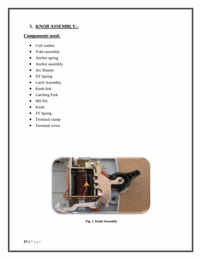
5. KNOB ASSEMBLY:-
Components used:
Coil washer
Yoke assembly
Anchor spring
Anchor assembly
Arc Runner
DT Spring
Latch Assembly
Knob link
Latching Fork
MS Pin
Knob
ST Spring
Terminal clamp
Terminal screw
Fig. 5. Knob Assembly

28 | P a g e
Steps of Knob Assembly:-
STAGE 1:
STAGE 2:
Tools used:-
1. Stage 1 : Coil washer fixture
2. Stage 2 : Coil Assembly Fixture , Modified Screw Driver , Nozeplyer
Coil Washer Outer Yoke Outer Yoke
Assembly
Outer Yoke
Assembly
Spotted Assembly
Anchor Assembly
Arc Runner
Anchor Spring
Knob Assembly

29 | P a g e
Fig. 6. The process flow Diagram For knob Assembly is shown below: -
Yoke Assembly Not Ok
Spring Strip OK
Coil Washer
Anchor Spring
DT Spring
REWORK
OK
Spotted Assembly
Inspection
Rework
Coil Assembly Anchor Assembly
DT Spring Fitting
Mechanism Fitting
Latch Assembly
M S Pin
Knob Assembly
with MS Pin
Complete Mechanism
Assembly
S T Spring Assembly
Terminal Assembly
Final Inspection
Go To MCB Assembly

30 | P a g e
Fig. 7. The process of Knob Assembly is better depicted from the following pictures: -

31 | P a g e
6. MCB ASSEMBLY:-
Miniature Circuit Breakers have precisely formed moulded case & cover of flame retardant high
strength thermo-plastic material having high melting point, low water absorption, high dielectric
strength and temperature with stand.
The Switching Mechanism is independent, manual and trip free, i.e., the breaker trips internally
even if the operating knob is held in ON position.
The Contact Mechanism comprises of fixed & moving contacts specially designed for
reliability, long life and anti-weld properties.
The Arc Extinguishing Device comprises of 15 plates arc chute. The arc under the influence of
the magnetic field and arc guide is moved into the
arc chute where it is rapidly split and quenched.
The tripping mechanism is Thermal Magnetic Type.
Thermal Operation:-
The thermal operation provides protection from moderate overloads. Under overload condition, a
thermo-metallic element (bimetallic strip) deflects
until it operates a latching mechanism allowing the main contacts to open.
Magnetic Operation:-
In magnetic operation, large overloads or short circuit current actuates a solenoid causing a
plunger to strike the latching mechanism rapidly opening
the main contacts.

32 | P a g e
Fig. 8. MCB ASSEMBLY AUTOMATION BLOCK DIAGRAM
MCB LOWER CHASIS BOWL FEEDER
CERAMIC PLATE FEEDER
ARC CHUTE LINEAR FEEDER
BACK PAPER LINEAR FEEDER
BACK PAPER BOWL FEEDER
KNOB ASSEMBLY(manual)
NUT BOWL FEEDER
SCREW DRIVER UNIT
CERAMIC PLATE FEEDER

33 | P a g e
CONVEYER BELT
MCB COVER CHASIS BOWL FEEDER
RIVET INSERTION UNIT
PICK AND PLACEFOR UNLOADING AND LOADING ON SPM
RIVETING AND TESTING SPM
FINAL END PRODUCT

34 | P a g e
Fig. 9. INTERNAL VIEW OF MCB:-

35 | P a g e
7. CONSTRUCTION AND OPERATION OF MCB: -
Construction: -
Miniature Circuit Breakers have precisely formed moulded case & cover of flame retardant high
strength thermo-plastic material having high melting point, low water absorption, high dielectric
strength and temperature with stand.
Working: -
The Switching Mechanism is independent, manual and trip free, i.e., the breaker trips internally
even if the operating knob is held in ON position.
The Contact Mechanism comprises of fixed & moving contacts specially designed for reliability,
long life and anti-weld properties.
The Arc Extinguishing Device comprises of 15 plates arc chute. The arc under the influence of
the magnetic field and arc guide is moved into the arc chute where it is rapidly split and
quenched.
The tripping mechanism is Thermal Magnetic Type.
Thermal Operation: -
The thermal operation provides protection from moderate overloads. Under overload condition, a
thermo-metallic element (bimetallic strip) deflects until it operates a latching mechanism
allowing the main contacts to open.
Magnetic Operation: -
In magnetic operation, large overloads or short circuit current actuates a solenoid causing a
plunger to strike the latching mechanism rapidly opening the main contacts.
Current Limiting Action: -
The high speed current limiting action ensures that the MCB operate before the full prospective
fault current is allowed to develop. Under fault conditions, damage can be sustained to the
installation and associated equipment due to the amount of energy that passes before the current
is completely interrupted. The total energy let through depends on the value of current and the
time for which it flows. The high speed current limiting action of MCB ensures that the energy
let through and any subsequent damage is minimized. This reduced LET THROUGH ENERGY
(Class 3 as per BSEN 60898) assists greatly with both backup and discrimination considerations.

36 | P a g e
Operating Mechanism: -
MCB have a quick make and break trip free mechanism. In the event of an over current or short
circuit the MCB automatically interrupts all poles even if the MCB toggle is held in ON position,
the handle always indicates the correct contact position.
Moderate Overload Condition: -
Detection of moderate Over load conditions is achieved by the use of a Bimetal Overload Relay,
which deflects in response to the current passing through it The Bimetal Relay moves against the
trip bar releasing the trip mechanism.
Short Circuit Conditions: -
When the current flowing through the MCB reaches a predetermined level, the solenoid in
Magnetic coil directly pulls in the plunger, which releases the trip mechanism.
Perfect Connections: -
The design of terminals makes the wiring easier. A combination box type terminal with
combination head screws on both sides with deep serrations ensures sparkles and firm
connections.
Outgoing Terminal
Body
Latch Arc-chutes Holder Solenoid Arc-chutes Arc-runner Arc-chutes Holder Fixed Contact Moving Contact Arm Incoming Terminal (Dual Termination)
w f MCB

37 | P a g e
8. CHARACTERISTICS CURVES AND TRIPPING
CHARACTERISTICS
Thermal Tripping Magnetic Tripping
As per No tripping Tripping Time Hold Trip Time
IS:8828:96 current current limits current current limit
I1 I2 t I4 I5 t
B Curve 1.13 x IN >1h 3xIN >0.1s
1.45 x IN <1h 5 x IN <0.1s
C Curve 1.13 x IN >1h 5xIN >0.1s
1.45 x IN <1h 10 x IN <0.1s
D Curve 1.13 x IN >1h 10xIN >0.1s
1.45 x IN <1h 20 x IN <0.1s
l3 = 2.55 x lN 1 s < t < 60s for lN < 32A
1 s < t < 120s for lN > 32A
TRIPPING CHARACTERISTICS
Based on the Tripping Characteristics, MCBs are available in ‗B‘, ‗C‘ and ‗D‘ curve to suit
different types of applications.
‗B‘ Curve: for protection of electrical circuits with equipment that does not cause surge current
(lighting and distribution circuits). Short circuit release is set to (3 - 5) In
‗C‘ Curve: for protection of electrical circuits with equipment that causes surge current
(inductive loads and motor circuits). Short circuit release is set to (5 - 10) In

38 | P a g e
‗D‘ Curve: for protection of electrical circuits which causes high inrush current, typically 12-15
times the thermal rated current (transformers, X-ray machines etc.) Short circuit release is set to
(10 - 20) In
Multiples of rated current
Fig. 10. Tripping Curves
Current Limiting Design: -
In a current limiting breaker, the tripping & arc control mechanism are so designed that under
short circuit conditions, the contacts are physically separated and the electrodynamic forces set
up by fault current, assist the extinction in less than half cycle.
The figure below shows the current limiting effect of circuit breakers.
Fault Traces for Voltage & Current
0 = Point of fault initiation
tx = Contact opening time (i.e., creation of arc)
t1 = Current / Voltage peak (i.e., current limitation)
t2 = Time to total extinction of arc
(i.e., complete shutdown of fault current)

39 | P a g e
Figure for the same is shown below.
Fig. 11. Current Limiting curve
Hammer Trip Mechanism: -
Current Limiting design in itself may not fulfill the requirement of quick breaking (instantaneous
action) mainly due to inertia of the Latch mechanism and interconnected sequence of operations.
A Hammer directly connected to the plunger strikes the moving contact arm with a force
proportional to the peak current thereby forcibly separating the moving contact from the fixed
contact much before the latch mechanism operates. This further reduces the opening time of the
circuit breaker.
Fig. 12. Hammer Tripping

40 | P a g e
Shunt Trip
1. To trip the Circuit Breaker through Shunt Trip Coil, 70% to 110% of the rated voltage is to be
applied across D1 & D2
2. The Shunt Trip coil is short time rated and it trips the breaker instantaneously. (i.e., continuous
duty not required)
Effect of Frequency Variation: -
MCBs are designed to operate at AC frequency 50 / 60 Hz. However, MCBs specially suitable
for DC applications and for frequencies upto 400Hz can be supplied on request.
These can be used on different frequencies in supply from 16 2/ 3 - 60 Hz without any duration.
For higher frequencies, normal MCBs can be used with a multiplication factor which shall only
affect its magnetic trip current.
Supply AC DC
Frequency 100Hz 200Hz 400Hz -
Multiplication Factor 1.1 1.2 1.5 1.5

41 | P a g e
9. DC APPLICATIONS: -
MCBs for DC application are specially designed to meet tough arc quenching conditions. While
selecting circuit breaker for DC applications following parameters have to be taken into
consideration.
Normal Circuit Currents:-
The rating and normal running temperature of the MCB are unaffected by DC. The MCB can be
selected using the thermal section of the standard time / current curves. Magnetic tripping on DC
is different from the equivalent AC by a peak factor of 1.4
i.e., for ‗B‘ curve AC MCB, magnetic range = (3-5) ln
for DC MCB, magnetic range = 1.4(3-5)ln = (4-7)ln
for ‗C‘ curve AC MCB, magnetic range = (5-10)ln
for DC MCB, magnetic range = 1.4(5-10)ln =(7-14)ln
Short Circuit Currents:-
The maximum short circuit current possible on a DC system is determined by the voltage of the
battery and the total internal resistance of the cells.
It is given by Ohm‘s law :
Isc = Vb / Rb
Where, Isc is the Short Circuit Current
Vb is the voltage of the battery (with 100% charged battery)
Rb is the internal resistance of the battery cells (this is usually stated by the manufacturer)
Circuit Time Constant:-
The time constant is given by : L/R
where L is the inductance of the circuit
R is the resistance of the circuit
The time constant is usually given in milliseconds (ms.). Ideally, DC circuits would be mainly
resistive (i.e. a low number), as inductive circuits produce a back emf when the current suddenly
falls. This in turn tends to prolong arcing during switching operations, and so reduce contact life.
Circuit Voltage: -
The voltage of the circuit is dependent upon the power supply. The lower the voltage the easier
switching operations will be, but the voltage makes no difference to the running of the MCBs.
Contact life can be significantly increased by reducing the voltage, drop accross each pole. This
can be achieved by wiring poles in series.
MCBs have been successfully tested on DC and can be used under the following conditions:
L/R 15ms max
Voltage 12-130V

42 | P a g e
10. SENSORS USED IN MCB AUTOMATION MACHINE:-
1. REED SWITCH:-
The reed switch is an electrical switch operated by an applied magnetic field. It
was invented at Bell Telephone Laboratories in 1936 by W. B. Ellwood. It consists of a pair
of contacts on ferrous metal reeds in a hermetically sealed glass envelope. The contacts may be
normally open, closing when a magnetic field is present, or normally closed and opening when a
magnetic field is applied. The switch may be actuated by a coil, making a reed relay,[1]
or by
bringing a magnet near to the switch. Once the magnet is pulled away from the switch, the reed
switch will go back to its original position.
An example of a reed switch's application is to detect the opening of a door, when used as
a proximity switch for a burglar alarm.
The reed switch contains a pair (or more) of magnetizable, flexible, metal reeds whose end
portions are separated by a small gap when the switch is open. The reeds are hermetically sealed
in opposite ends of a tubular glass envelope.

43 | P a g e
A magnetic field (from an electromagnet or a permanent magnet) will cause the reeds to come
together, thus completing an electrical circuit. The stiffness of the reeds causes them to separate,
and open the circuit, when the magnetic field ceases. Another configuration contains a non-
ferrous normally-closed contact that opens when the ferrous normally-open contact closes. Good
electrical contact is assured by plating a thin layer of non-ferrous precious metal over the flat
contact portions of the reeds; low-resistivity silver is more suitable than corrosion-
resistantgold in the sealed envelope. There are also versions of reed switches
with mercury "wetted" contacts. Such switches must be mounted in a particular orientation
otherwise drops of mercury may bridge the contacts even when not activated.
Since the contacts of the reed switch are sealed away from the atmosphere, they are protected
against atmospheric corrosion. The hermetic sealing of a reed switch make them suitable for use
in explosive atmospheres where tiny sparks from conventional switches would constitute a
hazard.
One important quality of the switch is its sensitivity, the amount of magnetic field necessary to
actuate it. Sensitivity is measured in units of Ampere-turns, corresponding to the current in a coil
multiplied by the number of turns. Typical pull-in sensitivities for commercial devices are in the
10 to 60 AT range. The lower the AT, the more sensitive the reed switch. Also, smaller reed
switches, which have smaller parts, are more sensitive to magnetic fields, so the smaller the reed
switch's glass envelope is, the more sensitive it is.
In production, a metal reed is inserted in each end of a glass tube and the end of the tube heated
so that it seals around a shank portion on the reed. Infrared-absorbing glass is used, so an
infrared heat source can concentrate the heat in the small sealing zone of the glass tube. The
thermal coefficient of expansion of the glass material and metal parts must be similar to prevent
breaking the glass-to-metal seal. The glass used must have a high electrical resistance and must
not contain volatile components such as lead oxide and fluorides. The leads of the switch must
be handled carefully to prevent breaking the glass envelope.

44 | P a g e
1. PHOTODIODE SENSORS:-
Photodiodes offer high sensitivity and low noise, enabling them to detect very low light levels.
However, they saturate above approximately 1mW/cm2, so attenuating filters must be used when
operating at higher powers, such as the Coherent 1000:1 accessory filter. Photodiodes also have a
fast response time, so they can be convenient for tuning and peaking lasers. Photodiodes have a
much more limited spectral range and lower spatial uniformity than thermal sensors. The latter
can affect the measurement repeatability of non-uniform beams or of beams that wander over the
detector surface between measurements. Photodiode sensors are not designed for use with pulsed
lasers. Coherent photodiode sensors are calibrated using a monochromator for use over their full
specified wavelength range.
The OP-2 sensors are directly compatible with the Coherent FieldMate, FieldMax II TO / TOP
and LabMax TO / TOP laser power meters. The LM-2 sensors must be used in conjunction with
the accessory SmartSensor adaptor. The OP-2 VIS sensor is available with selected meters at
reduced prices as part of Coherent's power meter value package programme. For testing the
power from optical fibres or fibre-coupled lasers, accessory fibre optic adaptors are available that
screw onto the photodiode sensor heads.

45 | P a g e
11. MCBTesting and Verification:-
This is a totally Modular System for Automatic Calibration Verification of Thermal
Trip characteristics of MCBs. The system is expandable from 1 station to ‗n‘ stations and
handles calibration of MCBs ranging from 0.5A to 120A. Each station is provided with one
MTCM CU for controlling the operation of that station. The MCB under test (its type / set of
calibration parameters) at each station is essentially independent of the other stations.
Consequentially, the user is free to calibrate different types of MCBs simultaneously
independent of each other. An interface module facilitates the communication between every
station the Windows based software that governs the system. Each station operates automatically
as soon as the MCB is switched ON after loading. The calibration i.e. adjustment of setscrew of
the MCB is done with the help of Stepper Motor. The PC in real time collects the ‗trip time‘ of
MCB under test and the result as Early, OK or Late. The same system can be used for
verification of the calibration wherein the tripping time with limits can be checked and hence the
system is also available without fixtures for verification (with manual calibration) only.
At the heart of the calibration system is the electronic DC Constant Current Source specially
designed for thermal calibration of MCBs. This source is more accurate than conventional
electrical source, designed for continuous duty, controlled by a dedicated micro-controller based
module (that sets the correct test current instantly) and is proven to be extremely rugged and
reliable. The architecture of the test system is modular and can be easily scaled up fast at a later
point in time, should there be a sudden rise in production requirement; meaning – for 10 station
bench, there would be 10 sources, 10 fixtures and 10 MTCMs. It is possible to add 1 or more
stations as and when required, instead of directly buying another test system. This is cost-
effective, guarantees zero down-time has many other benefits. The accompanying PC based
Testware is intuitive, has secured database and exports reports easily for statistical analysis such
as pare to analysis, bell-curve etc.

46 | P a g e
Magnetic Trip Test Bench
Test Bench will have:
1. Bench will enable checking instantaneous (Magnetic) Tripping of SP MCBs 0.5 to 63A.
for B & C curves. (CL.9.10.2) (Test Current will be pass through one pole only at any
given instant)
2. Test Current range will be from 3 In to 10 In i.e. 1.5A to 800 A settings.
3. Two independent variacs provided we will be able to set voltages for ‗Holding Test‘ &
‗Tripping Test‘ on two analog voltmeters provided.
4. CT Ranges will be 5-10-20-50-100-250-500-1000A.
5. Current will be measured through Transient Meter.
6. A Digital timer with 9.99 sec. range set for 0.2 sec. will be provided for current duration
control.
7. A Swamp resistor will be in series with Test MCB to increase P.F. of test circuit &
reduce asymmetry.
8. Current switching will be on secondary side to minimize asymmetry.
9. Transient meter will record current level through CT.
10. An auto ranging 4 digit DTIM will be provided to measure trip time with resolution of 1
msec.
11. Through 4 channel programmable time 4 SP, MCBs will be get tested in a very quick
sequence first holding current will be pass one by one in all 4 poles & then trip current
will be pass through one by one pole.
12. One toggle clamp operated fixture to be provided to accommodate 4 SP MCBs.
13. Bench will be floor standing.
14. A foot switch will be provided to initiate and stop the test.
Test Equipments for Circuit Breakers such as MCB, MCCB, ACB, VCB, RCCB & RCBO
and Compliance Verification Benches for conformity assessment as per IEC 60898, IEC
60947, IEC 61008, IEC 61009 & other standards.
We design and manufacture test equipments and automation solutions for testing and production
of circuit breakers such as Miniature Circuit Breakers (MCB), Molded Case Circuit Breakers
(MCCB), Residual Current Operated Circuit Breakers (RCCB / RCBO), Earth Leakage Circuit
Breakers (ELCB), Vacuum Circuit Breakers (VCBs), Air Circuit Breakers (ACBs) and other line
protection devices.
Some of our recent solutions are listed here. These facilitate testing of breakers as per various
standards such as IEC 60947, IEC 60898, IS 10322 and others. Please write to us for more
details about our all test equipments for MCBs.

47 | P a g e
Testing Solutions for MCB:-
o Thermal Calibration & Test Bench for MCB
o Thermal Trip Verification Test Bench for MCB
o Magnetic Trip Test Bench for MCB
o Time-Current Characteristics Test & Measurement System for Circuit Breakers
(MCB & RCBO)
o 3 Phase 28 days and Temperature Rise Test Bench for circuit breakers
o Temperature Rise & Power Loss Test Bench for MCB
o 3 Phase Endurance Test Bench for MCB
o Impulse Voltage Test Equipment for MCB

48 | P a g e
12. Testing Solutions for Miniature Circuit Breakers:-
Thermal Calibration Test Bench for Miniature Circuit Breakers for Thermal Calibration:-
This is a totally Modular System for Automatic Calibration Verification of Thermal Trip
characteristics of MCBs. The system is expandable from 1 station to ‗n‘ stations and handles
calibration of MCBs ranging from 0.5A to 120A. Each station is provided with one MTCM CU
for controlling the operation of that station. The MCB under test (its type / set of calibration
parameters) at each station is essentially independent of the other stations. Consequentially, the
user is free to calibrate different types of MCBs simultaneously independent of each other. An
interface module facilitates the communication between every station the Windows based
software that governs the system. Each station operates automatically as soon as the MCB is
switched ON after loading. The calibration i.e. adjustment of setscrew of the MCB is done with
the help of Stepper Motor. The PC in real time collects the ‗trip time‘ of MCB under test and the
result as Early, OK or Late. The same system can be used for verification of the calibration
wherein the tripping time with limits can be checked and hence the system is also available
without fixtures for verification (with manual calibration) only.
At the heart of the calibration system is the electronic DC Constant Current Source specially
designed for thermal calibration of MCBs. This source is more accurate than conventional
electrical source, designed for continuous duty, controlled by a dedicated micro-controller based
module (that sets the correct test current instantly) and is proven to be extremely rugged and
reliable. The architecture of the test system is modular and can be easily scaled up fast at a later
point in time, should there be a sudden rise in production requirement; meaning – for 10 station
bench, there would be 10 sources, 10 fixtures and 10 MTCMs. It is possible to add 1 or more
stations as and when required, instead of directly buying another test system. This is cost-
effective, guarentees zero down-time has many other benefits. The accompanying PC based
TestWare is intuitive, has secured database and exports reports easily for statistical analysis such
as compared to analysis, bell-curve etc.

49 | P a g e
MAIN FEATURES AT A GLANCE:
Fully Automatic ‗Stand Alone‘ Option (i.e. with or without PC).
ON line Loading of MCBs.
Can test MCBs ranging from 0.5 Amp to 120 Amp with suitable model.
Individual DC Constant Current Source with Fine Regulation; Multiplied Reliability and
Graceful Degradation.
Current setting: Automatic within +/- 0.3 % of set value.
Pneumatically operated electro-mechanical fixtures with stepper motor for calibration of
the MCB.
PC based operation; Selection of MCB its parameters from PC and/or MTCM for stand
alone option.
Early, OK Late indication on each Individual Display Unit as well as on PC at same
time.
Data Acquisition on PC by Windows based Software for traceability and statistical
analysis.
The solution comprises of:
1. Solid State DC Constant Current Source (with 0.2 % regulation) at each station.
2. Display & Control Unit for each station at each station.
3. Specially designed PC interface module.
4. Electro-pneumatically operated mechanical fixtures (test jigs) to hold MCB with Stepper
Motor for calibration of MCB at each station.
5. PC running Windows
6. TestWare - SCADA for control and data acquisition from the test equipment.
Models available are:
MTCM 20 A - With Current Range: 0.5A to 20A.
MTCM 100 A - With Current Range: 5A to 100A.
MTCM 200 A - With Current Range: 10A to 200A.
MTCM 300 A – With Current Range: 20A to 300A.
MTCM 400 A – With Current Range: 20A to 400A.

50 | P a g e
Thermal Trip Verification Test Bench for Miniature Circuit Breakers
The Thermal Trip Verification Test Bench is designed to perform thermal trip verification of
Miniature Circuit Breakers as per clause 9.10 of the IEC 60898. The working of the test system
is similar to the thermal trip calibration panel; however this system is to be used to verify the
tripping characteristics simulating the actual working conditions.
1. Test Ware - SCADA for control and data acquisition from the test equipment.
Fig. 13. Test Bench
Magnetic Trip Test Bench for Miniature Circuit Breakers
The MCB magnetic characteristics verification test bench is designed to perform magnetic trip
test on low voltage MCBs for short time over currents as per clause 9.10 of IEC 60898 (IS 8828).
B, C, and D curve of MCBs of single pole as well as multi-pole having different magnetic
characteristics can be measured on this test bench. The user can operate the entire test bench to
conduct all the available tests & measurements on MCB with a PC based TestWare; All
measurements are saved & reports (including current characteristics) can be generated. Decades
of experience has helped us to design current source (transformer) in a special way such that
good current regulation and enhanced accuracy is ensured. Our latest design has resulted in
variable current output source (short time) without a single variable transformer in the system.
Main Features at a glance:
Fully PC based test sequence with recording of all MCB measurements
Can test single as well as multi pole MCBs
Able to test B, C, D curve MCBs from 0.5 A to 63 A for holding test as well as magnetic
trip test
Pass/Fail Indication on PC screen for each pole on every test & measurement

51 | P a g e
The exact graph for current v/s time characteristics for better readability of the MCB
characteristics subjected to different tests
Storage of all test data including every measurement with bar code traceability in
database & built-in reporting for analysis - export option to Office/pdf/print.
Transient meter for recording peak current on test bench for stand-alone operation
The Test Bench comprises of:
1. Specially designed constant current source (with high current power transformer) for
accurate supply of current
2. PC to Test Bench interface card
3. Measurement system to measure instantaneous current
4. Test jig to load single/multi pole MCB
5. PC running TestWare
6. TestWare – SCADA with database & reporting for test & measurement of MCB magnetic
trip characteristics
Characteristics Test & Measurement System for Circuit Breakers (MCB & RCBO)
The Time Current Characteristics Test Solution for Circuit Breakers is designed to test &
measure the time v/s current waveforms for B, C, D curve MCBs for both thermal as well as
magnetic trip. The panel is programmed to typically follow the Table 7 of clause 8.6.1 of IEC
60898. It is suitable for RCBO (IEC 61009) also. It has an inbuilt current source to source
currents equivalent to those mentioned in the above mentioned table. All MCBs with range 0.5
Amp to 63 Amp can be tested on this panel. This panel has an in-built climatic chamber to
maintain temperatures of up to 45oC, which closely resembles the operating temperatures in the
environment where MCBs are installed in real world situations.
Main Features at a Glance:
Auto/Manual Test Selection Option
Constant current source of up to 500A continuous rating
Short time current rating up to 1500A
Both overload (thermal) trip test as well as instantaneous (magnetic) trip test is carried
out.
Servo Controller based output
Current swamping through specially designed graded inductors
Digital time interval meters to measure trip time
Bypass arrangement for breakers that have tripped
Transient recording meter to record exact tripping current for instantaneous (magnetic)
trip test
Control & Data Acquisition through PC based TestWare for traceability and statistical
analysis

52 | P a g e
Temperature Rise & Power Loss Test Bench for Miniature Circuit Breakers
Adjustable Constant Current Source will have:
1. 0.5A to 100A at 30V open ckt. Voltage CT range 2A, 5A, 10A, 25A, 50A, 100A.
2. The CT range and resistance for MCB rating to be selected through shorting links: 0.5A,
1A, 2A, 4A, 6A, 10A, 16A, 20A, 25A, 32A, 40A, 50A, 63A at 30V open current voltage.
3. Panel shall be capable for testing three samples of same rating may SP/DP/TP/FP
4. True RMS sensing current controller shall maintain current better than class 1.0 accuracy
throughout the range.
5. Digital Temperature Indicator min 28 Channels with minimum 28 No. Thermocouple
bid, Teflon insulated shall be provided with sufficient length to connect it to product.
6. Channel selection by rotary switch.
7. Cooling shall be provided by means of Exhaust fans distributed all over to remove the hot
air generated inside the panel cabinet.
8. Overall accuracy of the panel is better than class 1.0
9. The entire system will be housed in sturdy M-S Cabinet (Trolley)
10. Calibration certificate will be provided for individual meter and also for complete system.
11. Following meter indications will be provided:
o Digital Temperature Indicator with 28 input for thermocouple.
o Digital Volt Meter with 5 ranges (200mV, 2V, 20V, 200V, 250V) to measure
open circuit voltage & mV drop across MCB
o Digital Ammeter with CT (Indication on servo controller)

53 | P a g e
28 Days & Temperature Rise Test Panel for MCB (Single Phase)
The 3 station 28 days and temperature rise test panel is been developed to test MCBs, MCCBs,
RCCBs and RCBOs as per IEC 60898-1, IEC 61008-1, IEC 61009-1. In this test the MCB is
subjected to 28 cycles, each comprising 21hrs with rated Current at an open circuit Voltage of
more than 30V and 3hrs without Current. It consists of adjustable constant Current source which
provides constant Currents from 0 to 200A (180 A max.) at open circuit Voltage of more than
30V. Specially designed True RMS sensing Current controller maintains Current with the help of
stepper motor within+/-1 % throughout the range. Digital display is provided for Current
measurement. Microcontroller based sequential timer maintains the sequence of operation and
displays the test status.
Auto/Manual operation possible
Servo controlled mechanism to control current
Microcontroller based timer unit
The panel is capable to generate accurate test results for a continuous period of 28 days as
required in the 28 days test
Cooling shall be provided by means of Exhaust fans distributed all over to remove the hot
air generated inside the panel cabinet
True RMS sensing current controller shall maintain current better than class 1.0 accuracy
throughout the range
0.5A to 100A at 30V open circuit Voltage CT range 2A, 5A, 10A, 25A, 50A, 100A
The CT range and resistance for MCB rating to be selected through shorting links: 0.5A,
1A, 2A, 4A, 6A, 10A, 16A, 20A, 25A, 32A, 40A, 50A, 63A at 30V open current voltage
Overall accuracy of the panel is better than class 1.0
Digital Temperature Indicator with 28 input for thermocouple.
Digital Volt Meter with 5 ranges (200mV, 2V, 20V, 200V, 250V) to measure open circuit
voltage & mV drop across MCB
Digital Ammeter with CT (Indication on servo controller)

54 | P a g e
Temperature Rise & Power Loss Test Bench for Miniature Circuit Breakers
Adjustable Constant Current Source will have:
1. 0.5A to 100A at 30V open ckt. Voltage CT range 2A, 5A, 10A, 25A, 50A, 100A.
2. The CT range and resistance for MCB rating to be selected through shorting links: 0.5A,
1A, 2A, 4A, 6A, 10A, 16A, 20A, 25A, 32A, 40A, 50A, 63A at 30V open current voltage.
3. Panel shall be capable for testing three samples of same rating may SP/DP/TP/FP
4. True RMS sensing current controller shall maintain current better than class 1.0 accuracy
throughout the range.
5. Digital Temperature Indicator min 28 Channels with minimum 28 No. Thermocouple
bid, Teflon insulated shall be provided with sufficient length to connect it to product.
6. Channel selection by rotary switch.
7. Cooling shall be provided by means of Exhaust fans distributed all over to remove the hot
air generated inside the panel cabinet.
8. Overall accuracy of the panel is better than class 1.0
9. The entire system will be housed in sturdy M-S Cabinet (Trolley)
10. Calibration certificate will be provided for individual meter and also for complete system.
11. Following meter indications will be provided:
1. Digital Temperature Indicator with 28 input for thermocouple.
2. Digital Volt Meter with 5 ranges (200mV, 2V, 20V, 200V, 250V) to measure
open circuit voltage & mV drop across MCB
3. Digital Ammeter with CT (Indication on servo controller)
3 Phase MCB Endurance Test Bench
The test setup consists of 2 sub-systems:
3 Phase Inductive Load:
Inductive Load has 0.85 Power factor for Testing of MCBs of ranges 0.5, 1, 1.6, 2, 3, 4, 6, 8, 10,
13, 16, 20, 25, 32, 40, 45, 50, 63Amps, selectable with Shorting Links. The working voltage is
230V for each phase. There will be 3 Loads, which could be connected either in Single Phase or
3 Phase schemes. The resistance is ceramic tube based and insulated industrial grade.

55 | P a g e
Metering & Safety Features:
1. Micro Controller Based Programmable timer to set ON / OFF Time 0 – 99.9sec.
2. Digital Voltmeter with selector switch. Digital Ammeter with selector switch.
3. Digital Power Factor Meter. Digital Frequency Meter.
4. Electro Magnetic Counter: It will count the number of operations.
5. Current Sensing Circuit: To detect contact weld & contact open. This will give a signal to
cut off the Load, if fault persists for predefined time.
6. Electro Pneumatic Fixture. The ON / OFF Time & Sequence will be derived from Timer
Unit provided on metering panel.
Impulse Voltage Test Equipment MCB (Single Phase)
Impulse voltage tests are recommended with the object to determine effect of voltage stress on
insulating due to voltage surges of short durations, even when the switch (breaker) is off. A surge
is a form of over voltage, which may be defined as an exceptional voltage in excess of peak
voltage to earth at line or electrical system of which line forms a part (can be caused as a result
of lightning strikes as well as other overvoltage spikes in the power system level).
SCR ELEKTRONIKS has developed impulse tester for carrying out the following tests:
Low Voltage Switchgear and Control gear: IS/IEC 60947 -2004 Cl. No: 8.3.3.4.1
Circuit Breakers: IS/IEC 60898:2002 Cl.no.: 9.7.6.1 & 97.6.2
Residual Current Operated breakers: IEC 61008 & 61009 : Cl.no.: 9.20
Impulse Tester is designed to generate impulse voltage of 1.0 KV to 5 KV. The waveform
generated has rise time of 1.2 micro second and 50 micro second duration as defined in
IEC61180. The peak voltage can be adjusted continuously with the help of variac provided. The
test sequence i.e. number of Impulse for Positive and Negative polarity, time between two
subsequent impulses can be programmed through key pad with the help of dedicated PLC
module. The entire sequence, for both positive and negative impulse is automatic. At the end of
the test, the test results are displayed on LCD display. Output is provided for connecting an
oscilloscope for displaying the Wave Form at the output Terminals.
In case any flash over occurs, it is detected by a circuit which stops the test sequence, and output
PLC displays the number of cycles with polarities at which the failure has taken place.

56 | P a g e
Salient Features of the Impulse Voltage Tester:
Impulse Voltage -1kV to 5kV adjustable
Impulse Rise Time -1.2 micro sec. +/- 30%
Impulse Duration : 50 micro sec. +/- 20%
Sequencing : PLC module with setting of :
1. Positive, Negative or both polarities
2. No. of pulses for positive or Negative polarity
3. Duration between two consecutive Impulses
Selection of polarity: Automatic through PLC Unit
Voltage Indication: Digital Meter to indicate peak voltage
Output for Oscilloscope: Attenuated output 0 to 5V for 0 to 5kV
Mains Supply : 230 V AC, +/- 10% - 50Hz
Air Supply – Pressure – 5 Kg
The sequence is fully programmable and automatic
LCD Display for Indication of test parameters & result
Housed in extruded Aluminum Sections for better aesthetics

57 | P a g e
Unique Benefits of Thermal Calibration Test Bench for Miniature Circuit Breakers are:-
Aspect This Solution Conventional Equipment
Line & Load
Current
Regulation
Better than 0.3% 0.5% or 1%
Power
Consumption Low Normal
Test Voltage
/ Operator
Safety
No extra guards are required as
Individual
Station has its own P
Source &
maximum voltage is 7V
Higher Voltage is required for MCBs of
lower rating which calls for
special safety
precautions
Flexibility
You can spread the system to
different physical locations and
can test different types of
MCBs simultaneously
Fixed bench
Scalability
100%; System can have
1,2.3,...n stations as and when
required
No change can be made on existing
system
Reliability
Solid state components lead to
long life and less fatigue, No
interruption of current as there
is no need of change-over after
a breaker at a station trips
Interruption of current after a breaker trips
Maintenance
/
Breakdown
Individual Station can be
replaced or shut
down without affecting rest of
the system;
Failure of any one component is the failure
of
complete system; skilled technician required
for repairing

58 | P a g e
Easy 'plug & use' possible
Spares
Required
Modular system leads to lesser
spares /
inventory
Different types of spares required
Size Compact & Portable Medium; Mounted on Castors
Cost
No increase in cost for the last
5 years
Price directly dependant on fluctuating cost
of copper

59 | P a g e
13. SELECTION OF MCB
For household Applications
Appliances Capacity / Current Rating Type of MCB
watt (Load) of MCB
(240V~ 1ph)
Air Conditioner 1.0 tonnes 10A ―C‖ series
1.5 tonnes 16A ―C‖ series
2.0 tonnes 20A ―C‖ series
Refrigerator 165 litres 3A ―C‖ series
350 litre 4A ―C‖ series
Oven cum Griller 4500W 32A ―B‖ series
1750W 10A ―B‖ series
Oven only 750W 6A ―B‖ series
Hot Plate only 2000W 10A ―B‖ series
Room Heater 1000W 6A ―B‖ series
2000W 10A ―B‖ series
Washing Machine 300W 2A ―C‖ series
Washing Machine
(with heater) 1300W 8A ―C‖ series
Water Heater
(storage/instant) 1000W 6A ―B‖ series
2000W 10A ―B‖ series
3000W 16A ―B‖ series
6000W 32A ―B‖ series
Electric iron 750W 6A ―B‖ series
1250W 8A ―B‖ series
Auto Toaster
(2 slices) 1200W 8A ―B‖ series
Electric Kettle 1500W 10A ―B‖ series

60 | P a g e
For Motor Protection
1 Phase 230V 3 Phase 400V 3 Phase 400V Assisted Star Delta
kW HP Full Load MCB Full Load MCB Full Load MCB Selection
Current Selection Current Selection Current
C C C D
0.18 0.24 2.8 10 0.9 2 — — —
0.25 0.34 3.2 10 1.2 2 — — —
0.37 0.50 3.5 10 1.2 2 — — —
0.75 1.01 6.2 20 2.0 3 — — —
1.1 1.47 8.7 25 2.6 6 — — —
2.2 2.95 17.5 50 4.4 10 — — —
3 4.02 20.0 63 6.3 16 6.3 16 10
3.75 5.03 24.0 80 8.2 20 8.2 20 10
5.5 7.37 26.0 80 11.2 25 11.2 32 16
7.5 10.05 47.0 125 14.4 40 14.4 40 25
10 13.40 — — 21.0 50 21.0 50 32
15 20.11 — — 27.0 100 27.0 63 40
18.5 24.80 — — 32.0 125 32.0 — 50
22 29.49 — — 38.0 125 38.0 — 63
30 40.21 — — 51.0 125 51.0 — 63
Calculation Formulae:
Incomer Current Rating, For Single Phase:
Total Load in Watts
240V
Incomer Current Rating, For Three Phase:
Total Load in Watts
1.713X240V
61 | P a g e
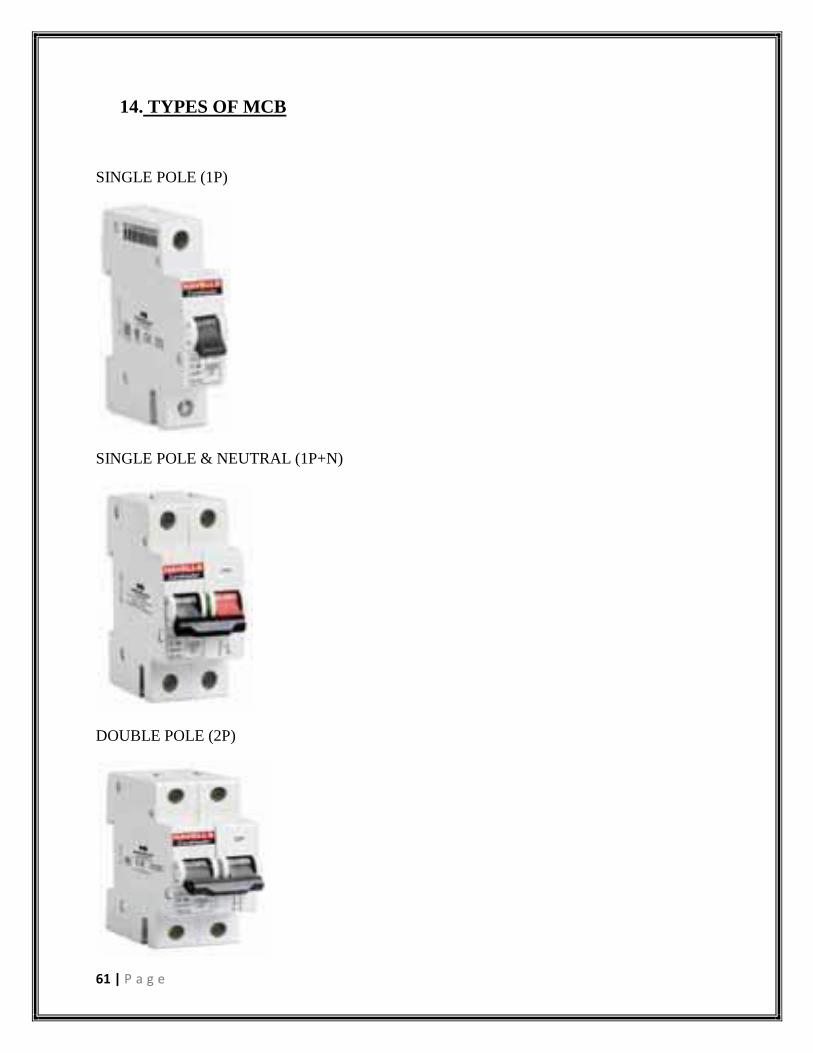
14. TYPES OF MCB
SINGLE POLE (1P)
SINGLE POLE & NEUTRAL (1P+N)
DOUBLE POLE (2P)

62 | P a g e
THREE POLE (3P)
THREE POLE - N (3P+N)
FOUR POLE (4P)
RAILWAY MCB

63 | P a g e
15. ERRORS AND CORRECTIONS:-
HV FAIL DUE TO LESS GAP BETWEEN CHORD AND FIXED CONTACT
MT FAIL DUE TO PLASTIC LATCH COLLIDES WITH POINTER
MT FAIL DUE TO ANCHOR PROFILE NOT OK
MT FAIL DUE TO ANCHOR JAM
HOLD/MT FAIL DUE TO MIXED RATING
HOLD FAIL DUE TO MCB TRIPPED OFF WITH THE JERKS OF TESTING PROBES
HOLD FAIL DUE TO LATCHING FORK CD NOT IN RANGE
HOLD/MT FAIL DUE TO WRONG RATING ANCHOR SPRING
HOLD FAIL DUE TO NO CONTINUITY
MT FAIL DUE TO PLUNGER MISSING
HOLD FAIL DUE TO CHORD BROKEN WITH THE COIL
MT FAIL DUE TO COIL NOT LOCKED WITH ARC RUNNER
HOLD FAIL DUE TO IMPROPER FITTMENT OF ASSEMBLY
MT FAIL DUE TO ALUMINIUM BUSH MISSING
MT FAIL DUE TO GAP IN COIL TURNS
MT FAIL DUE TO PLUNGER OUT OF ANCHOR ASSEMBLY
MT FAIL DUE TO ANCHOR SHORT
HOLD FAIL DUE TO NO CONTINUITY
MT FAIL DUE TO ULATCH LEG BEND
MT FAIL DUE TO COIL ENAMEL INSULATION REMOVED
MT FAIL DUE TOOPERATING FORK BEND
HOLD FAIL DUE TO SPOTTING BETWEEN BIMETAL AND CARRIER BROKEN
MT FAIL DUE TO U-LATCH RIVET TIGHT
The corrections to the above errors can be made by carefully carrying out the tests and by
completing all the respective steps involved in each test.
Abbreviations Used:-
HV: - High Voltage
MT: - Magnetic Tripping

64 | P a g e
16. REFERENCES:-
www.havells.com/Admin/Forms/Brochures/633981661886391116-DP Catalogue.pdf
http://en.wikipedia.org/wiki/User_interface
http://www.newtechmcb.net/
http://kr105793291.trustpass.alibaba.com/product/127254652-
0/Electric_parts_MCB_Automated_production_and_test_System.html?tracelog=ggsother
product1
http://www.alibaba.com/product-
tp/127254652/Electric_parts_MCB_Automated_production_and.html
http://www.abb.co.in/cawp/seitp202/268ba72cc7d2051f652578ce004414cf.aspx
http://uspatents.landoffree.com/patent/06482048
http://en.wikipedia.org/wiki/Spot_welding
http://gmc.tradeindia.com/arc-chute-assembly-for-mcb-s-563604.html
http://greenaircorp.en.alibaba.com/product/491611872-
209651836/Arc_chute_assembly_machine_for_MCB.html