austroads design vehicle and turning path templates
DESCRIPTION
Australian Vehicle Turning TemplatesTRANSCRIPT
Austroads Design Vehicle and Turning Path Templates

This page has been left blank intentionally.
Austroads Design Vehicles and Turning Path Templates
Austroads Design Vehicles and Turning Path Templates First Published 1995
This edition (2nd) 2006
© Austroads Inc. 2006
This work is copyright. Apart from any use as permitted under the Copyright Act 1968, no part may be reproduced by any process without the prior written permission of Austroads.
National Library of Australia Cataloguing-in-Publication data:
Austroads Design Vehicles and Turning Path Templates ISBN 1 921139 17 X
Austroads Project No. TP1093
Austroads Publication No. AP–G34/06
Project Manager John Cunningham, VicRoads
Prepared by
Rod George, ARRB Group
Published by Austroads Incorporated Level 9, Robell House 287 Elizabeth Street
Sydney NSW 2000 Australia Phone: +61 2 9264 7088
Fax: +61 2 9264 1657 Email: [email protected]
www.austroads.com.au
This Guide is produced by Austroads as a general guide. Its application is discretionary. Road authorities may vary their practice according to local circumstances and policies.
Austroads believes this publication to be correct at the time of printing and does not accept
responsibility for any consequences arising from the use of information herein. Readers should rely on their own skill and judgement to apply information to particular issues.
Austroads Design Vehicles and Turning Path Templates
Sydney 2006
Austroads profile Austroads is the association of Australian and New Zealand road transport and traffic authorities whose purpose is to contribute to the achievement of improved Australian and New Zealand road transport outcomes by:
undertaking nationally strategic research on behalf of Australasian road agencies and communicating outcomes
promoting improved practice by Australasian road agencies facilitating collaboration between road agencies to avoid duplication promoting harmonisation, consistency and uniformity in road and related operations providing expert advice to the Australian Transport Council (ATC) and the Standing Committee
on Transport (SCOT).
Austroads membership Austroads membership comprises the six state and two territory road transport and traffic authorities and the Commonwealth Department of Transport and Regional Services in Australia, the Australian Local Government Association and Transit New Zealand. It is governed by a council consisting of the chief executive officer (or an alternative senior executive officer) of each of its eleven member organisations:
Roads and Traffic Authority New South Wales Roads Corporation Victoria Department of Main Roads Queensland Main Roads Western Australia Department for Transport, Energy and Infrastructure South Australia Department of Infrastructure, Energy and Resources Tasmania Department of Infrastructure, Planning and Environment Northern Territory Department of Urban Services Australian Capital Territory Australian Department of Transport and Regional Services Australian Local Government Association Transit New Zealand
The success of Austroads is derived from the collaboration of member organisations and others in the road industry. It aims to be the Australasian leader in providing high quality information, advice and fostering research in the road sector.
AUSTROADS DESIGN VEHICLES AND TURNING PATH TEMPLATES
A u s t r o a d s 2 0 0 6
— i —
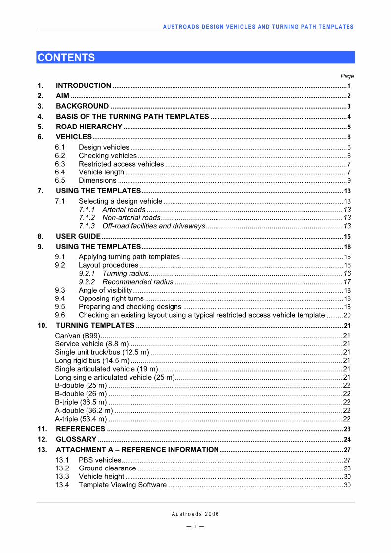
CONTENTS
Page
1. INTRODUCTION .................................................................................................................................1 2. AIM ........................................................................................................................................................2 3. BACKGROUND ..................................................................................................................................3 4. BASIS OF THE TURNING PATH TEMPLATES ...........................................................................4 5. ROAD HIERARCHY ...........................................................................................................................5 6. VEHICLES............................................................................................................................................6
6.1 Design vehicles .......................................................................................................................6 6.2 Checking vehicles ...................................................................................................................6 6.3 Restricted access vehicles ....................................................................................................7 6.4 Vehicle length ..........................................................................................................................7 6.5 Dimensions ..............................................................................................................................9
7. USING THE TEMPLATES...............................................................................................................13 7.1 Selecting a design vehicle ...................................................................................................13
7.1.1 Arterial roads .................................................................................................13 7.1.2 Non-arterial roads..........................................................................................13 7.1.3 Off-road facilities and driveways....................................................................13
8. USER GUIDE.....................................................................................................................................15 9. USING THE TEMPLATES...............................................................................................................16
9.1 Applying turning path templates .........................................................................................16 9.2 Layout procedures ................................................................................................................16
9.2.1 Turning radius................................................................................................16 9.2.2 Recommended radius ...................................................................................17
9.3 Angle of visibility....................................................................................................................18 9.4 Opposing right turns .............................................................................................................18 9.5 Preparing and checking designs ........................................................................................18 9.6 Checking an existing layout using a typical restricted access vehicle template .........20
10. TURNING TEMPLATES ..................................................................................................................21 Car/van (B99)........................................................................................................................21 Service vehicle (8.8 m)..........................................................................................................21 Single unit truck/bus (12.5 m) ...............................................................................................21 Long rigid bus (14.5 m) .........................................................................................................21 Single articulated vehicle (19 m) ...........................................................................................21 Long single articulated vehicle (25 m)...................................................................................21 B-double (25 m) ....................................................................................................................22 B-double (26 m) ....................................................................................................................22 B-triple (36.5 m) ....................................................................................................................22 A-double (36.2 m) .................................................................................................................22 A-triple (53.4 m) ....................................................................................................................22
11. REFERENCES ..................................................................................................................................23 12. GLOSSARY .......................................................................................................................................24 13. ATTACHMENT A – REFERENCE INFORMATION....................................................................27
13.1 PBS vehicles..........................................................................................................................27 13.2 Ground clearance .................................................................................................................28 13.3 Vehicle height ........................................................................................................................30 13.4 Template Viewing Software.................................................................................................30

This page has been left blank intentionally.
AUSTROADS DESIGN VEHICLES AND TURNING PATH TEMPLATES
A u s t r o a d s 2 0 0 6
— 1 —
1. INTRODUCTION All vehicles using the road network must be able to safely negotiate intersections without damaging other vehicles, buildings, infrastructure and roadside furniture. It is also important that vehicles negotiating intersections do not unduly obstruct traffic.
When a long vehicle makes a low-speed turn at an intersection, the rear of the vehicle covers a wider area than the inside of the path of the front of the vehicle. This is known as low-speed offtracking. The swept path is the road area covered by the outermost and innermost points of the vehicle making the low-speed turn. Since the road network consists of a hierarchy of roads with different functions, it is necessary to have a range of design vehicles in order to provide appropriate and safe access. This guide has been developed to assist intersection designers and contains:
user information (covering basis of turning templates and road hierarchy)
user guide
design vehicle dimensions
turning templates
user reference information (Performance Based Standards (PBS) vehicles, suggested ground and height clearance) in Appendix A
a software package to view and print these turning templates (Volo View Express).
AUSTROADS DESIGN VEHICLES AND TURNING PATH TEMPLATES
A u s t r o a d s 2 0 0 6
— 2 —
2. AIM These Austroads design vehicles have been produced to provide consistency when choosing an appropriate design vehicle for intersection design throughout Australia.
The design vehicles included in this document provide guidance to cover most normal intersection designs. Individual intersections should be designed and checked according to the vehicles expected to be negotiating these intersections.
Information on off-road manoeuvring, such as at parking bays and loading docks is not contained in this guide but is provided in AS 2890.2–2002 (Standards Australia 2002a).
AUSTROADS DESIGN VEHICLES AND TURNING PATH TEMPLATES
A u s t r o a d s 2 0 0 6
— 3 —
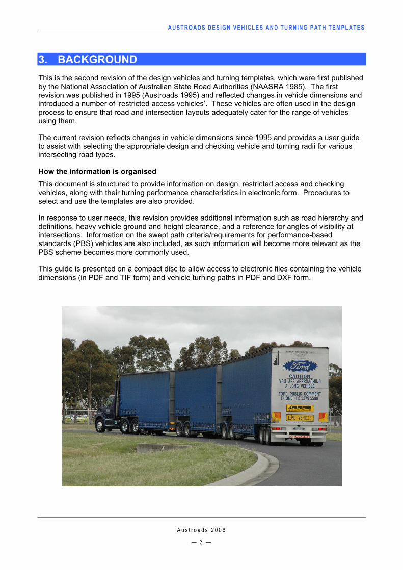
3. BACKGROUND This is the second revision of the design vehicles and turning templates, which were first published by the National Association of Australian State Road Authorities (NAASRA 1985). The first revision was published in 1995 (Austroads 1995) and reflected changes in vehicle dimensions and introduced a number of ‘restricted access vehicles’. These vehicles are often used in the design process to ensure that road and intersection layouts adequately cater for the range of vehicles using them.
The current revision reflects changes in vehicle dimensions since 1995 and provides a user guide to assist with selecting the appropriate design and checking vehicle and turning radii for various intersecting road types.
How the information is organised This document is structured to provide information on design, restricted access and checking vehicles, along with their turning performance characteristics in electronic form. Procedures to select and use the templates are also provided.
In response to user needs, this revision provides additional information such as road hierarchy and definitions, heavy vehicle ground and height clearance, and a reference for angles of visibility at intersections. Information on the swept path criteria/requirements for performance-based standards (PBS) vehicles are also included, as such information will become more relevant as the PBS scheme becomes more commonly used.
This guide is presented on a compact disc to allow access to electronic files containing the vehicle dimensions (in PDF and TIF form) and vehicle turning paths in PDF and DXF form.
AUSTROADS DESIGN VEHICLES AND TURNING PATH TEMPLATES
A u s t r o a d s 2 0 0 6
— 4 —
4. BASIS OF THE TURNING PATH TEMPLATES The vehicle turning path templates presented here are plots of the vehicle wheel path and the path traced by other relevant points on the vehicle or load. They show the swept path envelope resulting from various angles of turn at a particular radius measured to the outside front (steer) wheel. Thus the templates include not only the critical wheel paths but also the swept path of the front overhang and, where critical, the swept path of the rear overhang. The various turn radii given reflect an acceptable range of turn speed in normal traffic operation.
Note:
The templates provided have been developed as a guide for designing intersections (on-road use), or for vehicle access to and from on-road situations and represent only the forward movement of the vehicle. For the design of off-road facilities, such as designing layouts of parking lots and loading docks, lower absolute minimum and desirable minimum turning radii, as well as design vehicles which may not be included in this guide, may be more applicable. Australian Standards AS 2890.1-2004 for passenger vehicles and AS 2890.2-2002 for heavy vehicles should be used when designing off-road facilities (Standards Australia 2002a and 2004).
Throughout this document references to vehicle turning radii are measured to the outer edge of the outside front steer wheel.
AUSTROADS DESIGN VEHICLES AND TURNING PATH TEMPLATES
A u s t r o a d s 2 0 0 6
— 5 —
5. ROAD HIERARCHY It is important that common definitions and terms are used. The Australian Standard AS 1348-2002 (Standards Australia 2002b) provides a comprehensive glossary of terms for road and traffic engineering and definitions of roads from this standard have been included in the glossary in this document.
After consultation with a range of users from state and local government and consulting engineers on their use of the turning templates and suggestions for improvements, it was agreed that the following succinct definitions best describe the road terms in common use for the purpose of designing intersections.
Table 1: Suggested road type definitions for intersection design
Road term Definition
Local road/street1 A road or street used primarily for access to abutting properties (from AS 2890.1-2004).
Collector road/street
A non-arterial road which collects and distributes traffic in an area, as well as serving abutting properties (from AS 2890.1-2004). Provides access between local streets and sub-arterial roads.
Sub-arterial road A road connecting arterial roads to areas of development, and carrying traffic directly from one part of a region to another (from AS 1348–2002), and may relieve traffic on arterial roads.
Arterial road Provides access for through traffic from one region to another forming principal routes.
1 These could be disaggregated into sub-groups to cater for relevant accessing vehicles.
AUSTROADS DESIGN VEHICLES AND TURNING PATH TEMPLATES
A u s t r o a d s 2 0 0 6
— 6 —
6. VEHICLES
6.1 Design vehicles
The following three design vehicles as defined in Austroads (1995) have been retained for this revision:
single articulated (19 m)
single unit truck/bus (12.5 m)
service vehicle (8.8 m). The overall dimensions for the single articulated vehicle and the single unit truck/bus are specified in the Australian Vehicle Standards Rules (Australia 1999), rules 67, 68 and 69, and have not changed since the previous revision of the design vehicles. Whilst the dimensions of the design service vehicle are not covered in the above rules, (as a rigid vehicle has a maximum length of 12.5 m), the dimensions from Austroads (1995) have been retained. The internal dimensions of the single articulated vehicle have been updated to represent dimensions that reflect the maximum overall vehicle length.
The design service vehicle (8.8 m) represents domestic fire appliances and garbage vehicles, and the single unit truck/bus includes larger fire appliances which require access to certain parts of the road network, for example in industrial areas.
The design passenger vehicle is taken from the Australian Standard for Parking Facilities AS 2890.1-2004, using the B99 dimensions. The B99 dimensions represent the 99.8th percentile class of all cars and light vans on the road, and the rationale for adopting these is to ensure that the majority of passenger vehicles are considered when this design vehicle is used.
6.2 Checking vehicles
The design vehicle for a particular case is not necessarily the largest of the vehicles that may operate at that location (see User Guide). The design vehicle is intended to represent the majority of the vehicles allowed to operate at that location. A larger vehicle may not be precluded from this road, but may need to operate with reduced clearances or encroach into adjacent lanes. While this may inconvenience some road users, the low frequency of the occurrence of these vehicles makes this acceptable.
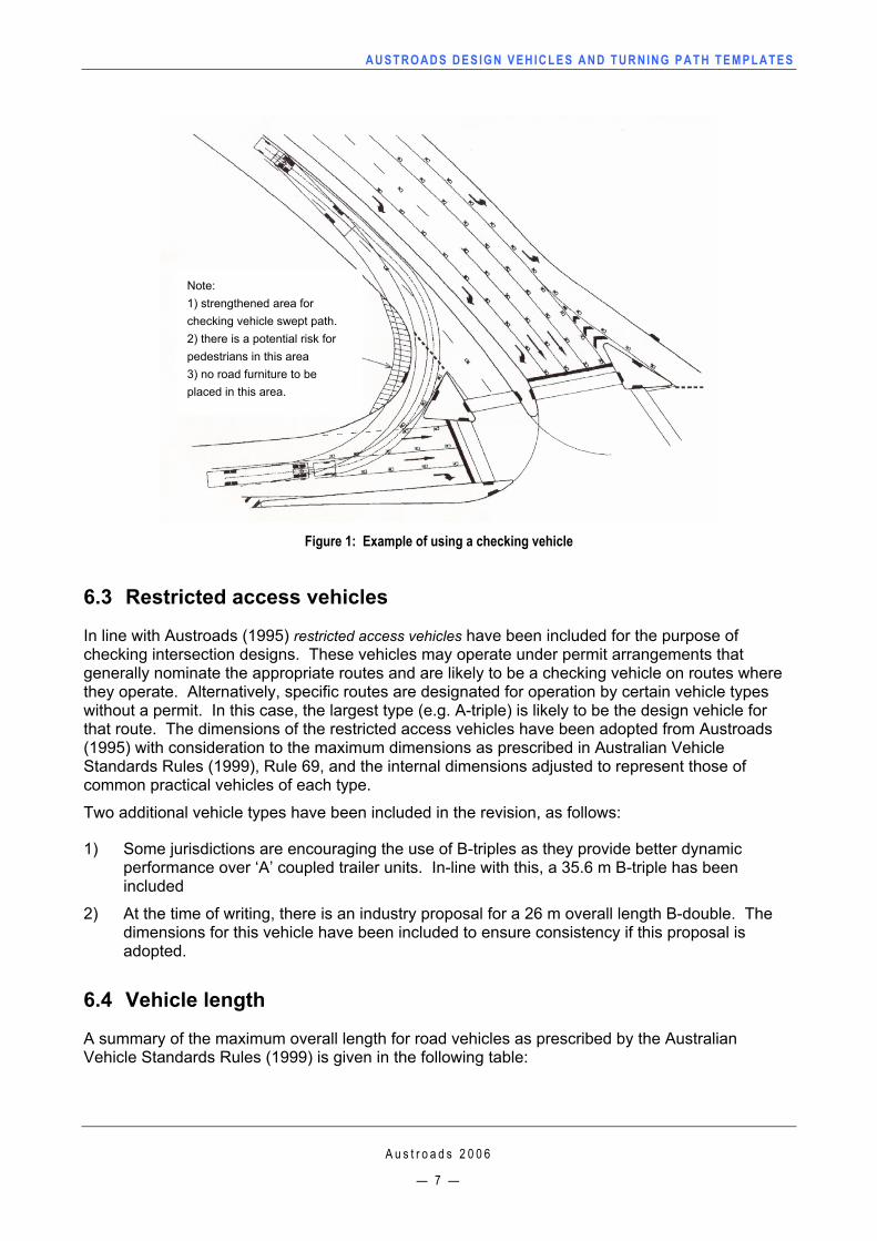
An appropriate checking vehicle must be used in order to ensure satisfactory operation of the larger vehicles. The checking vehicle will be chosen according to the potential for such vehicles to use the facility and will be at least the next larger vehicle to the design vehicle (see User Guide). Figure 1 shows an example of the provision for a check vehicle.
AUSTROADS DESIGN VEHICLES AND TURNING PATH TEMPLATES
A u s t r o a d s 2 0 0 6
— 7 —
Figure 1: Example of using a checking vehicle
6.3 Restricted access vehicles
In line with Austroads (1995) restricted access vehicles have been included for the purpose of checking intersection designs. These vehicles may operate under permit arrangements that generally nominate the appropriate routes and are likely to be a checking vehicle on routes where they operate. Alternatively, specific routes are designated for operation by certain vehicle types without a permit. In this case, the largest type (e.g. A-triple) is likely to be the design vehicle for that route. The dimensions of the restricted access vehicles have been adopted from Austroads (1995) with consideration to the maximum dimensions as prescribed in Australian Vehicle Standards Rules (1999), Rule 69, and the internal dimensions adjusted to represent those of common practical vehicles of each type.
Two additional vehicle types have been included in the revision, as follows:
1) Some jurisdictions are encouraging the use of B-triples as they provide better dynamic performance over ‘A’ coupled trailer units. In-line with this, a 35.6 m B-triple has been included
2) At the time of writing, there is an industry proposal for a 26 m overall length B-double. The dimensions for this vehicle have been included to ensure consistency if this proposal is adopted.
6.4 Vehicle length
A summary of the maximum overall length for road vehicles as prescribed by the Australian Vehicle Standards Rules (1999) is given in the following table:
Note: 1) strengthened area for checking vehicle swept path. 2) there is a potential risk for pedestrians in this area 3) no road furniture to be placed in this area.
AUSTROADS DESIGN VEHICLES AND TURNING PATH TEMPLATES
A u s t r o a d s 2 0 0 6
— 8 —
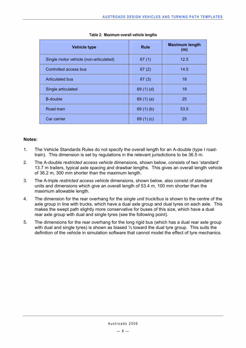
Table 2: Maximum overall vehicle lengths
Vehicle type Rule Maximum length (m)
Single motor vehicle (non-articulated) 67 (1) 12.5
Controlled access bus 67 (2) 14.5
Articulated bus 67 (3) 18
Single articulated 69 (1) (d) 19
B-double 69 (1) (a) 25
Road-train 69 (1) (b) 53.5
Car carrier 69 (1) (c) 25
Notes:
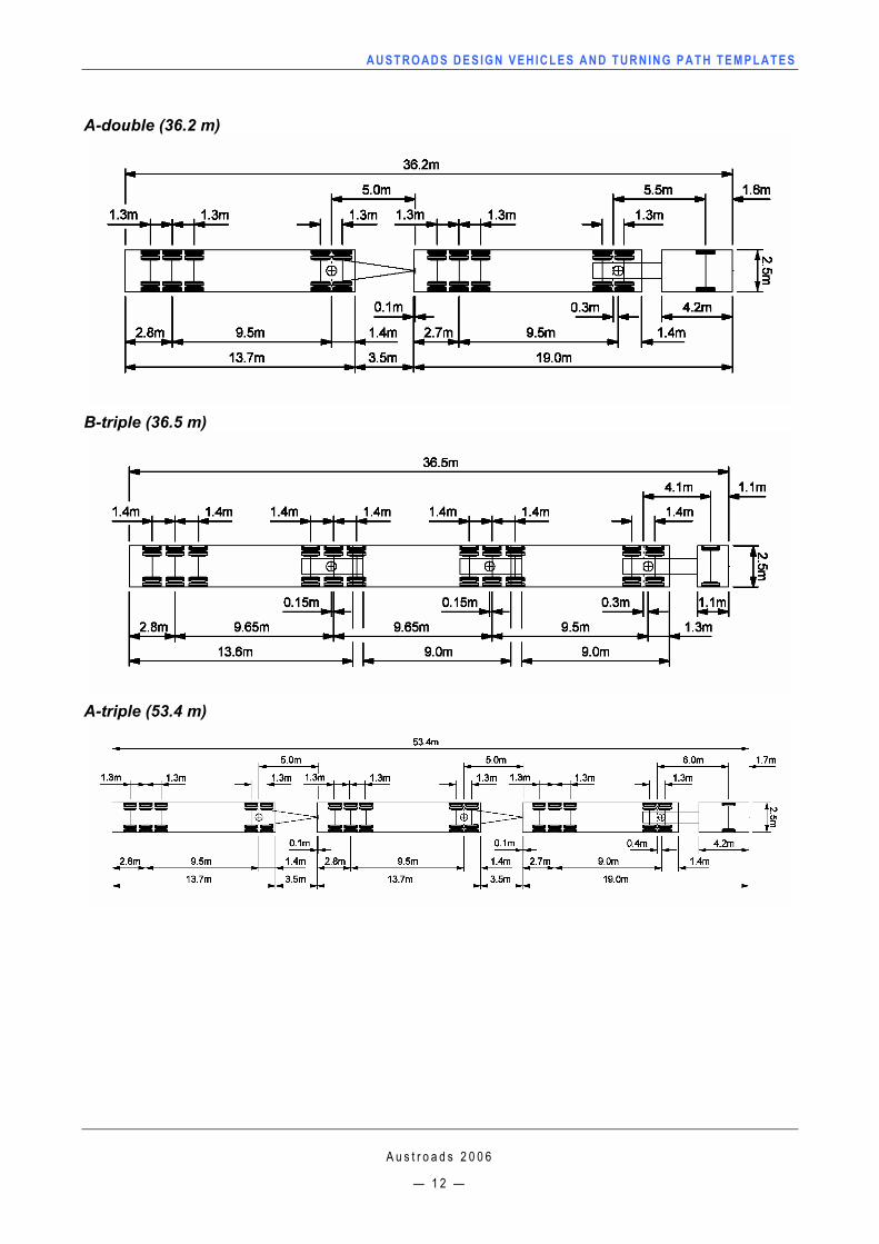
1. The Vehicle Standards Rules do not specify the overall length for an A-double (type I road-train). This dimension is set by regulations in the relevant jurisdictions to be 36.5 m.
2. The A-double restricted access vehicle dimensions, shown below, consists of two ‘standard’ 13.7 m trailers, typical axle spacing and drawbar lengths. This gives an overall length vehicle of 36.2 m, 300 mm shorter than the maximum length.
3. The A-triple restricted access vehicle dimensions, shown below, also consist of standard units and dimensions which give an overall length of 53.4 m, 100 mm shorter than the maximum allowable length.
4. The dimension for the rear overhang for the single unit truck/bus is shown to the centre of the axle group in line with trucks, which have a dual axle group and dual tyres on each axle. This makes the swept path slightly more conservative for buses of this size, which have a dual rear axle group with dual and single tyres (see the following point).
5. The dimensions for the rear overhang for the long rigid bus (which has a dual rear axle group with dual and single tyres) is shown as biased ⅓ toward the dual tyre group. This suits the definition of the vehicle in simulation software that cannot model the effect of tyre mechanics.
AUSTROADS DESIGN VEHICLES AND TURNING PATH TEMPLATES
A u s t r o a d s 2 0 0 6
— 9 —
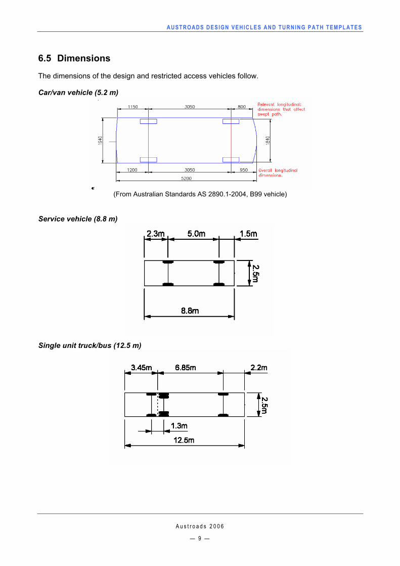
6.5 Dimensions
The dimensions of the design and restricted access vehicles follow.
Car/van vehicle (5.2 m)
(From Australian Standards AS 2890.1-2004, B99 vehicle)
Service vehicle (8.8 m)
Single unit truck/bus (12.5 m)

AUSTROADS DESIGN VEHICLES AND TURNING PATH TEMPLATES
A u s t r o a d s 2 0 0 6
— 1 0 —
Single articulated (19 m)
Long single articulated (25 m)
Long rigid bus (14.5 m)
AUSTROADS DESIGN VEHICLES AND TURNING PATH TEMPLATES
A u s t r o a d s 2 0 0 6
— 1 1 —
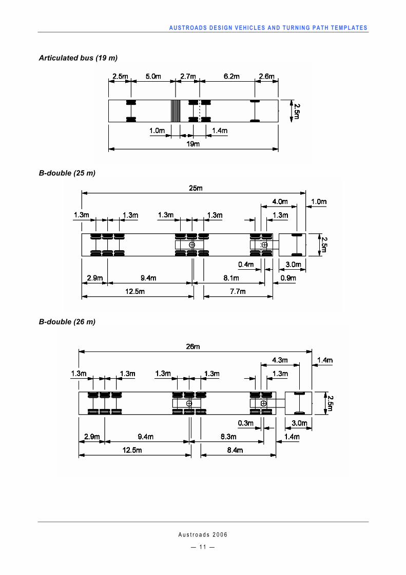
Articulated bus (19 m)
B-double (25 m)
B-double (26 m)
AUSTROADS DESIGN VEHICLES AND TURNING PATH TEMPLATES
A u s t r o a d s 2 0 0 6
— 1 2 —
A-double (36.2 m)
B-triple (36.5 m)
A-triple (53.4 m)
AUSTROADS DESIGN VEHICLES AND TURNING PATH TEMPLATES
A u s t r o a d s 2 0 0 6
— 1 3 —
7. USING THE TEMPLATES
7.1 Selecting a design vehicle
In general the choice of design and restricted access vehicles for on-road facilities will depend on the functional classification of the road or roads involved (e.g. at an intersection or driveway), the composition of the traffic and design economics. The following guide is provided for the selection of the design vehicle, and a user guide follows to assist the selection of an appropriate vehicle and turning radius.
Whilst the road network hierarchy has both functional and descriptive definitions, it is important that the land use, and hence the vehicle types that will be negotiating the intersections, be considered when determining appropriate design vehicles. For example, some local and collector roads service residential, industrial and bus routes, hence the design and restricted access vehicles and turning radii need to be appropriate for such cases. 7.1.1 Arterial roads
In general the design single articulated vehicle should be used for intersections involving two or more arterial roads. However, for other intersections on arterial roads such as with a collector road/street, the design single unit truck/bus will generally be more appropriate. Intersections between arterial roads and local roads should be designed using the service vehicle.
Where the design single unit truck/bus has been used to set up the intersection geometry, it is necessary to check the layout using the design single articulated vehicle template to ensure that the occasional use by these vehicles is viable. Similarly with the layout of major arterial roads (e.g. designated freight routes), the design is based on the design single articulated vehicle, and in some locations may need to be checked using the appropriate restricted access vehicle template to ensure that these vehicles are catered for where necessary. The procedures for this check are discussed below. 7.1.2 Non-arterial roads
The design single unit truck/bus should be used for works on collector and local roads and the design service vehicle is appropriate for intersections involving local streets. However, in both cases, while restrictive intersection geometry may be desired to meet traffic management and environmental objectives on local roads, it is necessary to check the layout using the next larger design vehicle template to ensure that occasional use by vehicles larger than the chosen design vehicle is viable. In this case the larger vehicle may be allowed to encroach into other traffic lanes (including the opposing traffic direction if the intersection is unsignalised) and travel over specially designed parts of traffic islands, etc. This is usually acceptable as the frequency of this occurrence and the inconvenience and risk to other traffic at these locations is minimal. For example, articulated vehicles delivering building materials in a new estate or furniture removal/delivery vehicles should be checked for their potential encroachment over kerb lines and possible interference with roadside furniture. 7.1.3 Off-road facilities and driveways
For off-road facilities, such as commercial and industrial sites, depots and loading docks, etc., the design vehicle chosen should be representative of the predominant, or critical, vehicle type expected to use the facility. This may or may not be one of the Austroads design vehicles.
AUSTROADS DESIGN VEHICLES AND TURNING PATH TEMPLATES
A u s t r o a d s 2 0 0 6
— 1 4 —
For car parks and driveways into residential properties the use of the design car will be appropriate, except where it is known that larger vehicles, such as a refuse collection truck, need to be catered for.
The following user guide is provided to assist when selecting the appropriate vehicle and turning template.
AUSTROADS DESIGN VEHICLES AND TURNING PATH TEMPLATES
A u s t r o a d s 2 0 0 6
— 1 5 —
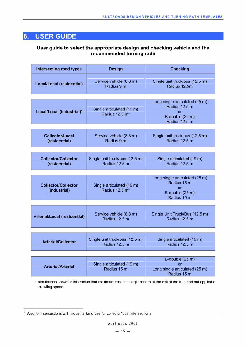
8. USER GUIDE User guide to select the appropriate design and checking vehicle and the
recommended turning radii
Intersecting road types Design Checking
Local/Local (residential) Service vehicle (8.8 m) Radius 9 m
Single unit truck/bus (12.5 m) Radius 12.5m
Local/Local (industrial)2 Single articulated (19 m) Radius 12.5 m*
Long single articulated (25 m) Radius 12.5 m
or B-double (25 m) Radius 12.5 m
Collector/Local (residential)
Service vehicle (8.8 m) Radius 9 m
Single unit truck/bus (12.5 m) Radius 12.5 m
Collector/Collector (residential)
Single unit truck/bus (12.5 m)Radius 12.5 m
Single articulated (19 m) Radius 12.5 m
Collector/Collector (industrial)
Single articulated (19 m) Radius 12.5 m*
Long single articulated (25 m) Radius 15 m
or B-double (25 m)
Radius 15 m
Arterial/Local (residential) Service vehicle (8.8 m) Radius 12.5 m
Single Unit Truck/Bus (12.5 m) Radius 12.5 m
Arterial/Collector Single unit truck/bus (12.5 m) Radius 12.5 m
Single articulated (19 m) Radius 12.5 m
Arterial/Arterial Single articulated (19 m) Radius 15 m
B-double (25 m) or
Long single articulated (25 m) Radius 15 m
* simulations show for this radius that maximum steering angle occurs at the exit of the turn and not applied at crawling speed.
2 Also for intersections with industrial land use for collector/local intersections
AUSTROADS DESIGN VEHICLES AND TURNING PATH TEMPLATES
A u s t r o a d s 2 0 0 6
— 1 6 —
9. USING THE TEMPLATES
9.1 Applying turning path templates
The fundamental principles in developing the turning templates are:
that the design vehicle should be able to turn (left or right) from a marked lane without crossing adjacent marked lanes
to prevent the rear of articulated vehicles from moving backwards at some point through the turn. This may occur when turning on a small radius through large angles, i.e. greater than 120 deg
that all vehicles that are considered in designing the intersection can negotiate the intersection without the rear wheels of the vehicle describing a small radius such that pavement surfacing is damaged.
Turning path templates, which are generally reproduced on transparent film as a design tool, are used to:
establish the width of pavement required at locations where vehicles execute significant turns (ie. large angles of turn at relatively small radii)
define the shape of the edge of the roadway, traffic islands, median ends, turning roadways and the alignment of traffic lanes etc. at intersections, median and separator openings, channelisation, entrances, etc.
establish the areas adjacent to turning roadways, traffic lanes and in traffic islands, etc., which are likely to be encroached upon by the swept path of checking vehicles including the area outside a vehicle’s wheel path (due to the front and rear overhang) which needs to be kept clear of road furniture and other fixed objects
define areas within traffic islands or on the road verge which may need to be strengthened or otherwise designed to carry the occasional heavy wheel loads when checking or restricted access vehicles are permitted to encroach outside the normal roadway limits.
These templates included in this guide can be imported into most drawing packages such as AutoCad and MicroStation. 9.2 Layout procedures
The procedures for using turning path templates in the layout design of road and other facilities are described below. These vary slightly, depending on whether a new layout is being developed, or an existing layout design is being checked, e.g. to identify the capability of a layout to cater for vehicles larger than the design vehicle.
9.2.1 Turning radius
The minimum turning radius of a vehicle depends on a number of parameters, such as the hauling unit steering geometry, wheelbase and number of trailing axles, and the number of trailing units. However, the minimum radius that should be used for design purposes also has to cover other factors such as driver ability, driver behaviour, operational efficiency and operational safety.
AUSTROADS DESIGN VEHICLES AND TURNING PATH TEMPLATES
A u s t r o a d s 2 0 0 6
— 1 7 —
For on-road situations, the absolute minimum radius3 for intersection design has to cover the capabilities of all vehicles that may be expected to operate in a particular location. This means that the absolute minimum radius has to be confidently achieved by all of the vehicles using that intersection. For the single-unit truck/bus and the 19 m single articulated vehicle the absolute minimum radius has been set at 12.5 m which represents the required turning circle (kerb to kerb) for these vehicles under ADR 43/04 (DOTRS 1999). For each design vehicle, the absolute minimum turning radius for on-road situations requires the vehicle to slow to almost a stop before making the turn. However, the driver is not required to stop and change lock on the spot before making the turn.
The desirable minimum radius for intersection design ensures operating efficiencies through higher turning speed, greater scope to accommodate driver variability and the ability to accommodate changes in the vehicle fleet over time.
The turn radius selected should be representative of the expected speed of turning vehicles and the type of turning vehicles.
Vehicle modelling and turning path simulations generally use a tangential turn.
4This is because the vehicle is aligned with the entrance tangent for the circular turn with the front (steered) wheels pointing straight ahead. Due to the characteristics of vehicle steering geometry, there is a transient state (or distance) where it is possible for the front wheels of a vehicle travelling at slow speed to follow a circular path while the steering angle is changed from straight ahead to close to the maximum angle. This confirms that no instantaneous change in steering angle is required at the start of any circular curve.
Tangential turns should always be used for the design of intersection turns, and for turns from the roadway into a property access. In practice, drivers may sometimes execute turns after applying some initial lock while the vehicle is stopped. This is due to factors such as driver error, constraints imposed by low standard geometry, disabled vehicles or obstacles on the road. Initial lock turns require shorter arcs of turn but involve maximum off-tracking for more of the turn, and greater outswing of the rear of the vehicle at the start of the turn. Initial lock turns are relevant for off-street manoeuvres (including roadside parking manoeuvres) and, in constrained situations, for entering and leaving parking spaces but not for circulating roadways within a parking facility.
9.2.2 Recommended radius
The recommended minimum turning radius for the design vehicles when negotiating the intersections at appropriate speeds are:
single unit truck/bus: 12.5 m based on ADR 43/04
single articulated vehicle (19 m): 12.5 m based on ADR 43/04
service vehicle: 9 m based on achievable capability
long single articulated vehicle (25 m): 15 m based on desirable operating efficiencies
B-double (25 m): 15 m based on desirable operating efficiencies.
3 the radius which allows vehicle turning at a range of steering locks at appropriate intersection speeds without reverse movement of the vehicle. 4 This text is from Queensland Dept of Main Roads (2002)
AUSTROADS DESIGN VEHICLES AND TURNING PATH TEMPLATES
A u s t r o a d s 2 0 0 6
— 1 8 —
9.3 Angle of visibility
When designing intersections there is a need to ensure that drivers of heavy vehicles have appropriate visibility angles when turning at intersections. Furthermore, when providing intersection road space for large turning vehicles, it is necessary to check that car drivers are not encouraged to turn with inappropriate visibility angles.
Information on acceptable visibility required for intersections is available in Austroads (2004) Guide to Traffic Engineering Practice Part 5 – Intersections at Grade section 6.4.
9.4 Opposing right turns
Where opposing right turns operate simultaneously, the turns should be designed to provide sufficient clearance between the left sides of the swept paths of opposing vehicles (i.e. not wheel-tracks) as follows:
single turns 1.0 m
1 single and 1 double turn 2.0 m
double turns 2.0 m. The following turning path templates should be used to design intersection geometry for opposing turns:
single turn – 19 m articulated vehicle, minimum radius of 15 m
double turn – articulated vehicle/car abreast, minimum radius of 15 m. Further information on opposing right turns for intersections is available in Austroads (2004) section 6.7.5.8.
9.5 Preparing and checking designs
The following steps are recommended to prepare and check a design layout. Using transparencies of the turning templates at the required scale:
1. Select the appropriate design vehicle as discussed in Section 7.
2. Select the template with the radius of turn matching (as near as practicable) the turn required, bearing in mind the geometric controls of the site and the most likely vehicle turning speed. As discussed above, the use of the absolute minimum turn radius should be avoided on arterial roads and at other important traffic sites. Each of the templates indicates a range of appropriate speed values for the radius of turn chosen.
3. Correctly align the template within the lane from which the turn is to be made.
Note:
The templates are oriented for left turns and therefore the reverse side of the transparency may be used for right turns.
4. Note the angle of turn required and rotate the template, about the centre of the turning radius until the nearest greater angle given on the template matches the exit direction. (This requires rotation of the template in the opposite direction to that of the vehicle movement).
AUSTROADS DESIGN VEHICLES AND TURNING PATH TEMPLATES
A u s t r o a d s 2 0 0 6
— 1 9 —
5. Mark/note the vehicle’s wheel path.
6. If a reverse curve is involved (e.g. as in the layout of a roundabout), particular care needs to be taken in allowing for the transition of the wheel path from one direction to the other. Considerable skill is required to correctly achieve this with the use of conventional single radius uni-directional turning path templates. In critical situations, designers are encouraged to use commonly available computer based turning path prediction software models which permit the swept path and wheel tracks to be plotted for a design vehicle following a complex turn path made up of arcs and tangents.
7. Design vehicle turning path templates should be applied to ensure that:
The outside edge of the swept path remains within the paved area.
A minimum offset of 0.6 m is provided between the inside wheel paths and face of kerb or pavement edge.
The 0.6 m offset need not be provided for local streets in urban areas where space is restricted or local access/minor roads in rural areas where the shoulder is partly sealed. However, it is desirable that the vehicle (i.e. swept path) should not cross the centreline of a minor rural road. A minimum clearance of 0.6 m outside the swept path should be provided to objects such as road furniture (see definition) and utility poles.
In situations where space is restricted and turning speed is low, it may be necessary to allow the swept path of the design vehicle to encroach into a verge or traffic island with the wheel paths remaining on the pavement. This may occur when designing for a large bus to use a local street, or when checking that a design layout can accommodate an occasional vehicle larger than the design vehicle. The long rigid bus may be appropriate for checking designs on arterial roads.
Note: Experience and engineering judgement should be used when applying clearances
Where computer programs are not available, the designer may graphically check a layout design that involves a reverse turn by the following method: use the appropriate template to plot a trace, by hand, of both the outer front wheel path and the inner rear wheel path for the design vehicle, in the direction of the first turn. The reverse side of the template should then be used to check the opposite direction of the turn by overlaying the template and aligning the wheel paths previously traced. The template should be aligned so that the inner rear wheel path on the template is tangential to the outer front wheel path already plotted, and, simultaneously, the outer front wheel path is tangential to the inner rear wheel path already plotted. The template will need to be rotated in order to maintain this requirement and to fit within the design controls at the site.
While this procedure may not exactly reflect the actual positioning of the vehicle as it moves through the reverse curve, experience has shown that the wheel paths plotted using this technique sufficiently match the actual wheel path plots produced using one of the computer-based turning path models.

AUSTROADS DESIGN VEHICLES AND TURNING PATH TEMPLATES
A u s t r o a d s 2 0 0 6
— 2 0 —
9.6 Checking an existing layout using a typical restricted access vehicle template
A common practice in layout design and traffic management is to check an existing intersection layout to verify its adequacy to cater for vehicles larger than the design vehicle on which the layout was based, e.g. checking vehicle on freight routes (see discussion under ‘Selecting a design vehicle’ on page 13). This includes the identification of areas outside the normal roadway limits (as defined by the kerb and channel or the edge of the pavement), which need to be specially strengthened or otherwise treated to cater for the occasional movement of a larger vehicle.
The typical restricted access vehicle templates may also be used, together with other relevant criteria such as environmental impacts, to check existing roads and intersections to identify routes capable of catering for the various restricted access vehicles.
The restricted access vehicle templates are also useful in the layout design of industrial facilities used predominantly by large vehicles.
The procedure for carrying out this check is basically the same as used in initial layout design using design vehicle turning path templates except in respect to positioning of the template on the intersection layout plan. Whereas the appropriate design vehicle template would normally be positioned within the correct turn lane for the vehicle movement in question, a template representing a larger vehicle (usually a restricted access vehicle) may be placed in a more favourable starting position outside the normal turn lane. Although, the design vehicle wheel path would be confined within the normal roadway, as mentioned above, the wheel path of a restricted access vehicle may not be so constrained and may encroach into other traffic lanes, islands or the verge areas where this is acceptable and appropriate provision has been made.
This reflects the Traffic Regulations which permit these large vehicles to encroach into other traffic lanes when turning, and it is generally uneconomical to design for them to turn from the normal marked turn lanes, except where they comprise a high proportion of the traffic and the consequences of their interference with other traffic cannot be tolerated. This is the case at signalised intersections where encroachment across the centreline will generally not be possible because of the presence of queuing vehicles in the street being turned into. The same may also be true where a raised median exists and designers should be aware of these constraints.
AUSTROADS DESIGN VEHICLES AND TURNING PATH TEMPLATES
A u s t r o a d s 2 0 0 6
— 2 1 —
10. TURNING TEMPLATES The turning templates for the design and restricted access vehicles are in the relevant folders for each vehicle and turning radii. Note: some templates do not show the tyre paths however the maximum swept path is shown on all templates.
Car/van (B99) 6.3 m radius
Service vehicle (8.8 m) 9 m radius, 5 km/h 12.5 m radius, 5 km/h 15 m radius, 5 to 15 km/h 20 m radius, 15 to 20 km/h 30 m radius, 20 to 30 km/h
Single unit truck/bus (12.5 m) 12.5 m radius, 5 km/h 15 m radius, 5 to 15 km/h 20 m radius, 15 to 20 km/h 30 m radius, 20 to 30 km/h
Long rigid bus (14.5 m) 12.5 m radius, 5 km/h 15 m radius, 5 to 15 km/h 20 m radius, 15 to 20 km/h 30 m radius, 20 to 30 km/h
Single articulated vehicle (19 m) 12.5 m radius, 5 km/h 15 m radius, 5 to 15 km/h 20 m radius, 15 to 20 km/h 30 m radius, 20 to 30 km/h
Car and a single articulated vehicle (19 m) 15 m radius, 5 to 15 km/h 20 m radius, 15 to 20 km/h 30 m radius, 20 to 30 km/h
Long single articulated vehicle (25 m) 12.5 m radius, 5 km/h 15 m radius, 5 to 15 km/h 20 m radius, 15 to 20 km/h 30 m radius, 20 to 30 km/h
AUSTROADS DESIGN VEHICLES AND TURNING PATH TEMPLATES
A u s t r o a d s 2 0 0 6
— 2 2 —
B-double (25 m) 12.5 m radius, 5 km/h 15 m radius, 5 to 15 km/h 20 m radius, 15 to 20 km/h 30 m radius, 20 to 30 km/h
B-double (26 m) 12.5 m radius, 5 km/h 15 m radius, 5 to 15 km/h 20 m radius, 15 to 20 km/h 30 m radius, 20 to 30 km/h
B-triple (36.5 m) 15 m radius, 5 to 15 km/h 20 m radius, 15 to 20 km/h 30 m radius, 20 to 30 km/h
A-double (36.2 m)
Note: The maximum length permitted for an A-double is 36.5 m, however the overall length of the vehicle combination below is 36.2 m which reflects typical dimensions.
15 m radius, 5 to 15 km/h 20 m radius, 15 to 20 km/h 30 m radius, 20 to 30 km/h
A-triple (53.4 m)
Note: The maximum length permitted for an A-triple is 53.5 m, however the overall length of the vehicle combination below is 53.4 m which reflects typical dimensions.
15 m radius, 5 to 15 km/h 20 m radius, 15 to 20 km/h 30 m radius, 20 to 30 km/h
AUSTROADS DESIGN VEHICLES AND TURNING PATH TEMPLATES
A u s t r o a d s 2 0 0 6
— 2 3 —
11. REFERENCES
Australia 1999, Australian vehicle standards rules 1999, Statutory Rules 1999 No. 1 made under the Road Transport Reform (Vehicles and Traffic) Act 1993, AGPS, Canberra ACT.
Austroads 1995, Design vehicles and turning templates, AP-34/95, Austroads, Sydney, NSW.
Austroads 2005, ‘Guide to traffic engineering practice: Part 5 – Intersections at grade’. Austroads, Sydney, NSW.
Department of Transport and Regional Services 1999, Vehicle configuration and dimensions, Australian Design Rule 43/04, DOTARS, Canberra ACT.
Luk J, McLean JR, Styles, E & George, RM 2004, Interim PBS road classification guidelines, contract report RC3066-3. ARRB Transport Research, Vermont South, Vic.
Queensland Department of Main Roads 2001, ‘Traffic parameters and human factors’, in Road planning and design manual, Queensland Dept of Main Roads, Brisbane, Qld, p.5-67
NAASRA 1985, Design vehicles and turning templates, National Association of Australian State Road Authorities, Sydney, NSW.
Prem H, McLean, JR & Edgar J 2003, PBS safety standards for heavy vehicles, NRTC discussion paper, National Transport Commission, Melbourne Vic.
Standards Australia 2002a, Parking facilities. Part 2: off-street commercial vehicle facilities, AS 2890.2–2002, Standards Australia, Sydney, NSW.
Standards Australia 2002b, Road and traffic engineering – glossary of terms, AS 1348–2002, Standards Australia, Sydney, NSW.
Standards Australia 2004, Parking facilities, part 1: off-street car parking. AS/NZS 2890.1–2004, Standards Australia, Sydney, NSW.
AUSTROADS DESIGN VEHICLES AND TURNING PATH TEMPLATES
A u s t r o a d s 2 0 0 6
— 2 4 —
12. GLOSSARY
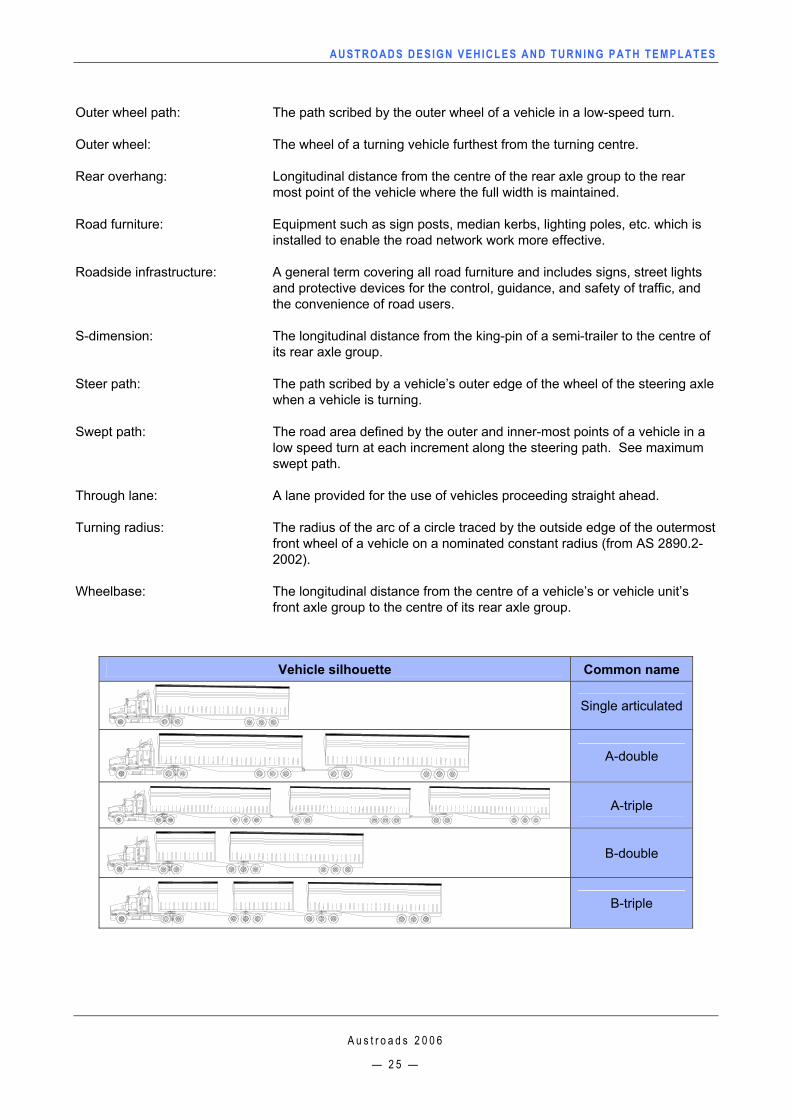
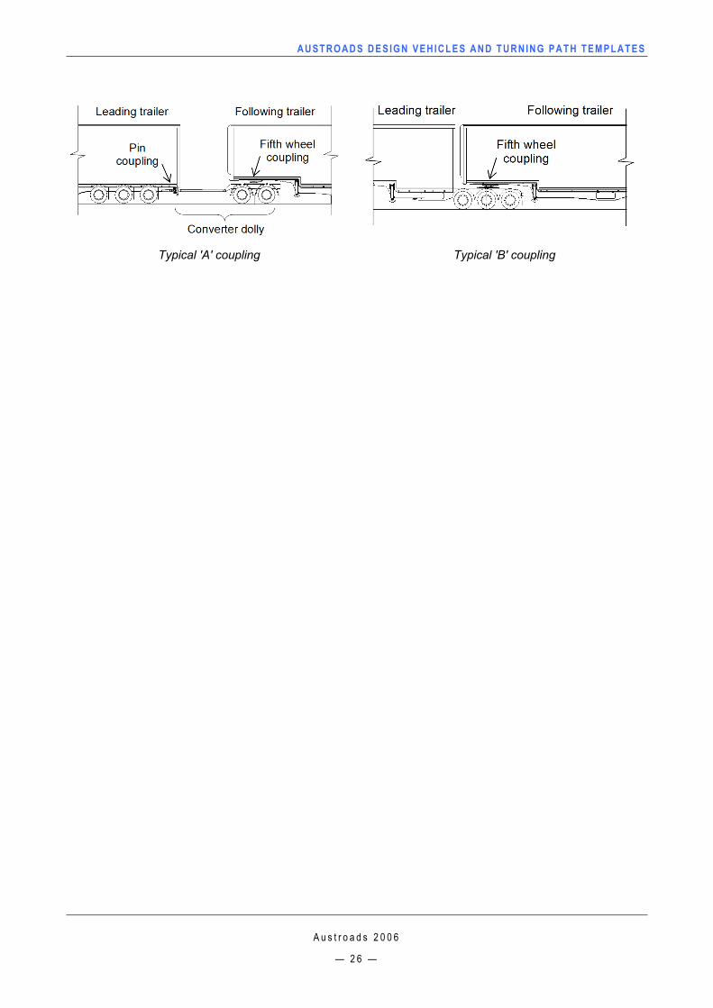
A-double: A multi-combination vehicle consisting of a prime mover towing 2 semi-trailers connected with converter dollies (see diagram and vehicle silhouette below).
As of right vehicles: Vehicle that are permitted access to the whole road network, they are generally not longer than 19 m.
A-triple: A multi-combination vehicle consisting of a prime mover towing 3 semi-trailers connected with converter dollies (see diagram and vehicle silhouette below).
B99 vehicle: The design motor car whose physical dimensions represent the 99.8th percentile class of all cars and light vans on the road (from AS 2890.1–2004).
B-double: A combination vehicle consisting of a prime mover towing 2 semi-trailers where the trailer are connected with fifth wheels (see diagram below). The first semi-trailer is connected to the prime mover by a fifth wheel coupling and the second semi-trailer is connected to the first semi-trailer by a fifth wheel coupling (see vehicle silhouette below).
B-triple: A combination vehicle similar to a B-double with an additional trailer (see vehicle silhouette below).
Clearance height: The minimum height for which a structure should be designed to accommodate the design vehicles. (Maximum allowable vehicle heights are generally 0.2 m less than this height) (from AS 2890.2-2002).
Converter dolly A vehicle unit that converts a semi-trailer to a full trailer, generally consists of a turntable (fifth wheel), a draw bar and an axle group (see diagram below).
Front overhang: Longitudinal distance from the steer axle to the foremost point of the vehicle where the full width is maintained.
Inner wheel path: The path scribed by the inner wheel of a vehicle in a low-speed turn.
Inner wheel: The wheel of a turning vehicle closest to the turning centre.
Long single articulated vehicle: An extendable semi-trailer or low loader for transporting an indivisible item.
Maximum swept path: The maximum vehicle excursion defined by the outer and inner-most points of a vehicle in a low speed turn along a prescribed steering path. See swept path.
Minor service area: A service area occasionally served by heavy rigid vehicles or with provision for not more than a total of ten medium rigid and smaller commercial vehicles (from AS 2890.2-2002).
Off-tracking: The lateral distance that the last axle on the rear trailer tracks from the path of the steer axle, usually used for low-speed movements.
AUSTROADS DESIGN VEHICLES AND TURNING PATH TEMPLATES
A u s t r o a d s 2 0 0 6
— 2 5 —
Outer wheel path: The path scribed by the outer wheel of a vehicle in a low-speed turn.
Outer wheel: The wheel of a turning vehicle furthest from the turning centre.
Rear overhang: Longitudinal distance from the centre of the rear axle group to the rear most point of the vehicle where the full width is maintained.
Road furniture: Equipment such as sign posts, median kerbs, lighting poles, etc. which is installed to enable the road network work more effective.
Roadside infrastructure: A general term covering all road furniture and includes signs, street lights and protective devices for the control, guidance, and safety of traffic, and the convenience of road users.
S-dimension: The longitudinal distance from the king-pin of a semi-trailer to the centre of its rear axle group.
Steer path: The path scribed by a vehicle’s outer edge of the wheel of the steering axle when a vehicle is turning.
Swept path: The road area defined by the outer and inner-most points of a vehicle in a low speed turn at each increment along the steering path. See maximum swept path.
Through lane: A lane provided for the use of vehicles proceeding straight ahead.
Turning radius: The radius of the arc of a circle traced by the outside edge of the outermost front wheel of a vehicle on a nominated constant radius (from AS 2890.2-2002).
Wheelbase: The longitudinal distance from the centre of a vehicle’s or vehicle unit’s front axle group to the centre of its rear axle group.
Vehicle silhouette Common name
Single articulated
A-double
A-triple
B-double
B-triple
AUSTROADS DESIGN VEHICLES AND TURNING PATH TEMPLATES
A u s t r o a d s 2 0 0 6
— 2 6 —
Typical 'A' coupling Typical 'B' coupling
AUSTROADS DESIGN VEHICLES AND TURNING PATH TEMPLATES
A u s t r o a d s 2 0 0 6
— 2 7 —
13. ATTACHMENT A: REFERENCE INFORMATION
13.1 PBS vehicles
The information in this section is provided as background information.
A key principle of Performance-Based Standards (PBS) for heavy vehicles is the focus on what the vehicle must be able to do rather than what it looks like, ie. its prescribed dimensions. With innovation, it is possible for vehicles designed under this principle to carry more load but be safer and have better or equivalent performance to similar ‘standard’ vehicles.
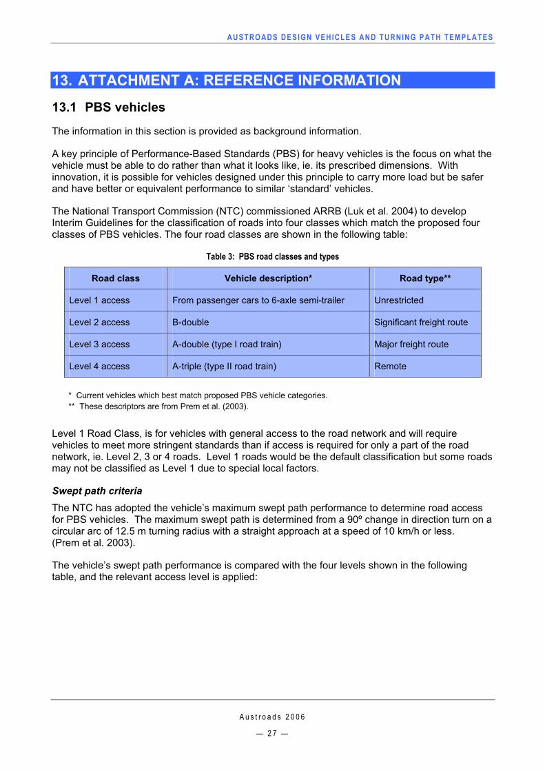
The National Transport Commission (NTC) commissioned ARRB (Luk et al. 2004) to develop Interim Guidelines for the classification of roads into four classes which match the proposed four classes of PBS vehicles. The four road classes are shown in the following table:
Table 3: PBS road classes and types
Road class Vehicle description* Road type**
Level 1 access From passenger cars to 6-axle semi-trailer Unrestricted
Level 2 access B-double Significant freight route
Level 3 access A-double (type I road train) Major freight route
Level 4 access A-triple (type II road train) Remote
* Current vehicles which best match proposed PBS vehicle categories. ** These descriptors are from Prem et al. (2003).
Level 1 Road Class, is for vehicles with general access to the road network and will require vehicles to meet more stringent standards than if access is required for only a part of the road network, ie. Level 2, 3 or 4 roads. Level 1 roads would be the default classification but some roads may not be classified as Level 1 due to special local factors.
Swept path criteria The NTC has adopted the vehicle’s maximum swept path performance to determine road access for PBS vehicles. The maximum swept path is determined from a 90º change in direction turn on a circular arc of 12.5 m turning radius with a straight approach at a speed of 10 km/h or less. (Prem et al. 2003).
The vehicle’s swept path performance is compared with the four levels shown in the following table, and the relevant access level is applied:
AUSTROADS DESIGN VEHICLES AND TURNING PATH TEMPLATES
A u s t r o a d s 2 0 0 6
— 2 8 —
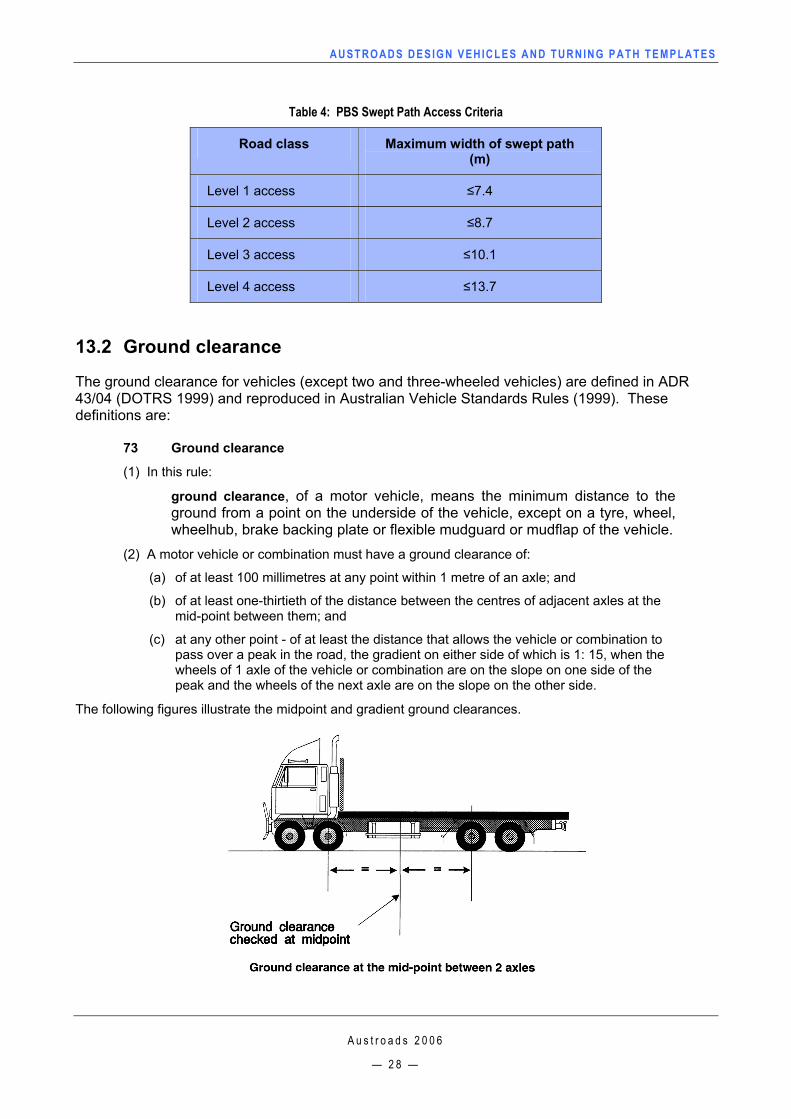
Table 4: PBS Swept Path Access Criteria
Road class Maximum width of swept path (m)
Level 1 access ≤7.4
Level 2 access ≤8.7
Level 3 access ≤10.1
Level 4 access ≤13.7
13.2 Ground clearance
The ground clearance for vehicles (except two and three-wheeled vehicles) are defined in ADR 43/04 (DOTRS 1999) and reproduced in Australian Vehicle Standards Rules (1999). These definitions are:
73 Ground clearance
(1) In this rule:
ground clearance, of a motor vehicle, means the minimum distance to the ground from a point on the underside of the vehicle, except on a tyre, wheel, wheelhub, brake backing plate or flexible mudguard or mudflap of the vehicle.
(2) A motor vehicle or combination must have a ground clearance of:
(a) of at least 100 millimetres at any point within 1 metre of an axle; and
(b) of at least one-thirtieth of the distance between the centres of adjacent axles at the mid-point between them; and
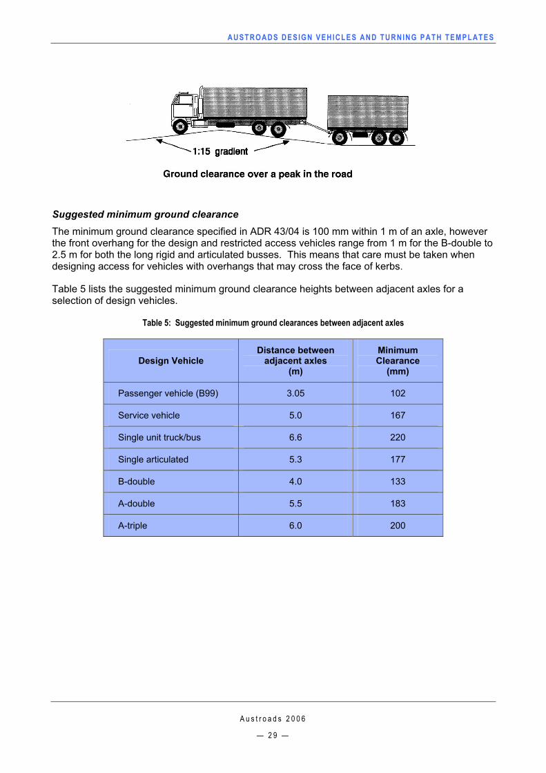
(c) at any other point - of at least the distance that allows the vehicle or combination to pass over a peak in the road, the gradient on either side of which is 1: 15, when the wheels of 1 axle of the vehicle or combination are on the slope on one side of the peak and the wheels of the next axle are on the slope on the other side.
The following figures illustrate the midpoint and gradient ground clearances.
AUSTROADS DESIGN VEHICLES AND TURNING PATH TEMPLATES
A u s t r o a d s 2 0 0 6
— 2 9 —
Suggested minimum ground clearance The minimum ground clearance specified in ADR 43/04 is 100 mm within 1 m of an axle, however the front overhang for the design and restricted access vehicles range from 1 m for the B-double to 2.5 m for both the long rigid and articulated busses. This means that care must be taken when designing access for vehicles with overhangs that may cross the face of kerbs.
Table 5 lists the suggested minimum ground clearance heights between adjacent axles for a selection of design vehicles.
Table 5: Suggested minimum ground clearances between adjacent axles
Design Vehicle Distance between
adjacent axles (m)
Minimum Clearance
(mm)
Passenger vehicle (B99) 3.05 102
Service vehicle 5.0 167
Single unit truck/bus 6.6 220
Single articulated 5.3 177
B-double 4.0 133
A-double 5.5 183
A-triple 6.0 200
AUSTROADS DESIGN VEHICLES AND TURNING PATH TEMPLATES
A u s t r o a d s 2 0 0 6
— 3 0 —
13.3 Vehicle height
Maximum vehicle heights are defined in ADR 43/04 and reproduced in Australian Vehicle Standards Rules (1999). These definitions are:
72 Height
(1) A vehicle must not be more than 4.3 m high.
(2) However:
(a) a vehicle built to carry cattle, sheep, pigs or horses must not exceed 4.6 metres high; and
(b) a double-deck bus must not exceed 4.4 metres high.
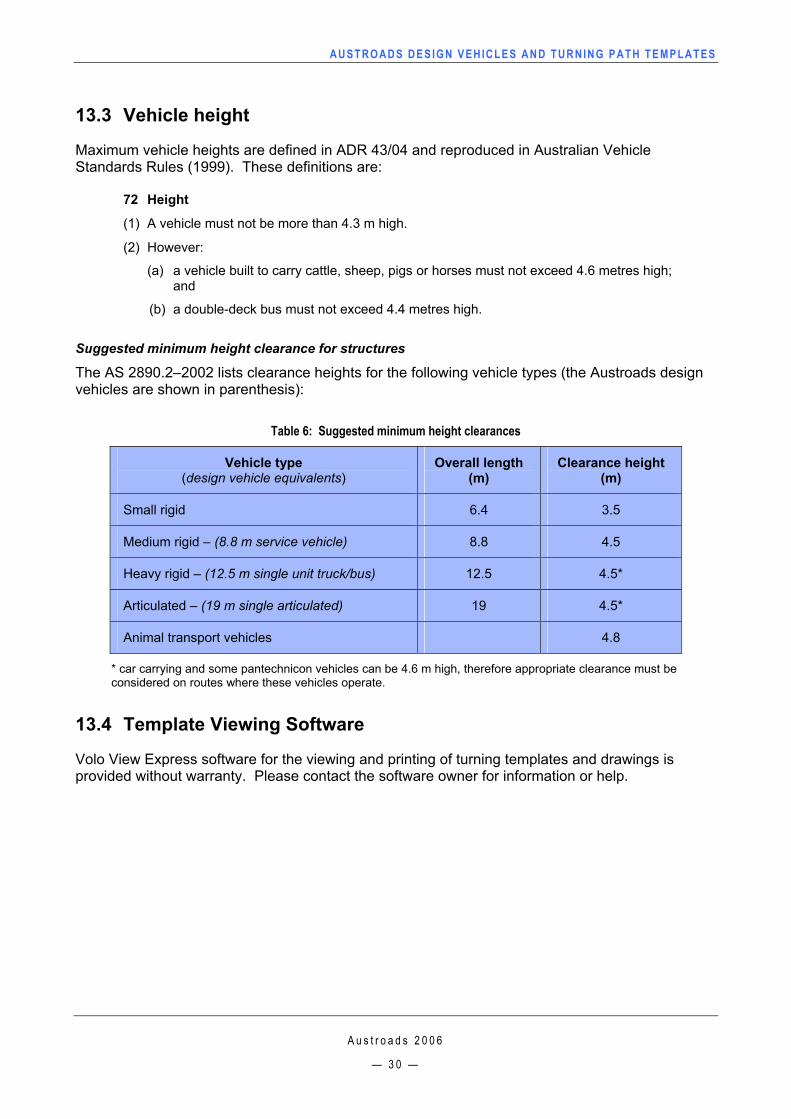
Suggested minimum height clearance for structures
The AS 2890.2–2002 lists clearance heights for the following vehicle types (the Austroads design vehicles are shown in parenthesis):
Table 6: Suggested minimum height clearances
Vehicle type (design vehicle equivalents)
Overall length (m)
Clearance height (m)
Small rigid 6.4 3.5
Medium rigid – (8.8 m service vehicle) 8.8 4.5
Heavy rigid – (12.5 m single unit truck/bus) 12.5 4.5*
Articulated – (19 m single articulated) 19 4.5*
Animal transport vehicles 4.8
* car carrying and some pantechnicon vehicles can be 4.6 m high, therefore appropriate clearance must be considered on routes where these vehicles operate.
13.4 Template Viewing Software
Volo View Express software for the viewing and printing of turning templates and drawings is provided without warranty. Please contact the software owner for information or help.
AUSTROADS DESIGN VEHICLES AND TURNING PATH TEMPLATES
A u s t r o a d s 2 0 0 6
— 3 1 —
INFORMATION RETRIEVAL
Austroads (2006), Austroads Design Vehicles and Turning Path Templates, Sydney, A4, 37pp, plus turning templates Keywords: Intersection design, road geometry, swept path, vehicle type, specifications Abstract: The 2006 Austroads Design Vehicles and Turning Path Templates provides a guide for traffic intersection designers. The guide contains a series of turning path (swept path) templates for a range of design and checking vehicles from passenger cars, single unit trucks, buses, to articulated and multiple-combination vehicles, such as B-doubles and road trains. For each vehicle type a representative range of turning radii and angles of turn are given. The templates are provided in electronic form that can be printed and copied onto a transparent medium or imported into computer drawing packages to check vehicle paths on intersection layout drawings.

NOTES

NOTES

NOTES