attachments catalogue no - challenge implements · buckets • pag e 2 all general purpose buckets...
TRANSCRIPT

ATTACHMENTS CATALOGUE • NO.9

Loader Buckets pages 2-6
Loader Post Hole Diggers page 7
Loader Blades pages 8-9
Loader Hay Handling pages 10-11
Hay Tines page 11
Loader Silage Handling pages 12-13
Loader Lifting pages 14-15
Loader Multicarriage page 16
3-Point Linkage pages 17-24
Telehandler page 25

Over 60 Years of History
Challenge Implements is a tractor loader and attachment specialist with its major manufacturing plant situated in Orange, New South Wales, approximately 260 kilometres west of Sydney. Orange is a regional city with a population of 39,000 and the area is promoted as the agribusiness capital of New South Wales. Main agricultural activities in the surrounding area include: cereal and oilseed production; wool and prime lambs; beef; dairies; apple, pear and stone fruit orchards; grapes and vineyards; vegetables; flowers and pine plantations.
Challenge is a fully Australian-owned third-generation family company.
Challenge commenced manufacturing agricultural implements in Orange in 1957 with two employees and a capital of less than £500. The ultimate aim of the company was to develop a representative range of everyday agricultural equipment. Steps were taken even in the first year of operation to divert every available penny toward the necessary research and development required to produce such equipment.
The year 1962 marked the release of the first Challenge front end loader along with a three-point linkage grader. These products gained immediate market acceptance and established the brand name ‘Challenge’ as implements of good design, robust in construction and offering value for money.
Today Challenge continues to grow by expanding its operations throughout Australia. This allows Challenge to continue to support Australian farmers with fast, prompt and reliable service, with equipment designed by Australians for Australian conditions.
From the very first loader made by Challenge in 1962, this Australian-owned company and its brand has created enviable traditions of world-class engineering excellence and innovation.

BU
CK
ETS
• pa
gE
2
All general purpose buckets have been designed to meet the high strength and safety requirements of today’s environment. There is a large variety of buckets available to cover a wide range of applications and to enable a more compatible loader/tractor combination, ensuring you get the most from your loader.
All buckets are constructed from high tensile steel (570mpa) which is laser cut for accuracy and press formed to ensure superior strength.
When attached to a Challenge front end loader, the bucket profile has been designed to ensure there is no rollback, a condition whereby material spills or falls over the rear of the bucket as it is filled. All earthmoving buckets enable maximum fill with minimum effort, ensuring an efficient loading cycle.
The lower back portion of the bucket has a double plate arrangement that forms an enclosed 'box' section running the full width of the bucket, giving the bucket exceptional torsional strength.
Buckets have a high quality roll formed cutting edge for excellent durability as well as wear plates on the bottom face of the bucket.
Heavy section pipe gives a clean smooth face to the top of the bucket.
The buckets' cut ends have been pressed to give strength along the edge and sides of the bucket.
The attachment lugs on the rear of the bucket have plates that distribute the load to the strengthened sections of the bucket, directly behind the ‘box’ section and to the formed edge towards the top of the bucket. This eliminates deformation in the back of the bucket during loading cycles.
Most general purpose buckets can be fitted with ground-engaging teeth if required.
100098
D²
D¹
H¹

BU
CK
ETS • pag
E 3
CompaCT ‘LCC’ MId ‘LCM’ Low CapaCiTy ‘LC’ HigH CapaCiTy ‘HC’Model 134LCC 150LCC 170LCC 186LCM 186LC 216LC 246LC 216HC 246HC
Horse power range 21-45 hp 21-45 hp 21-45 hp 45-70 hp 55-360 hp 55-360 hp 55-360 hp 55-360 hp 55-360 hp
Width 1340 mm 1500 mm 1700 mm 1860 mm 1860 mm 2160 mm 2460 mm 2160 mm 2460 mm
Weight 62 kg 78 kg 88 kg 178 kg 190 kg 220 kg 245 kg 240 kg 265 kg
Depth (D¹) 460 mm 490 mm 575 mm 665 mm 672 mm 672 mm 672 mm 787 mm 787 mm
Overall depth (D²) 695 mm 740 mm 805 mm 940 mm 964 mm 964 mm 964 mm 1040 mm 1040 mm
Height (H¹) 425 mm 445 mm 495 mm 600 mm 657 mm 657 mm 657 mm 700 mm 700 mm
Struck capacity 0.13 m³ 0.17 m³ 0.25 m³ 0.38 m³ 0.47 m³ 0.55 m³ 0.63 m³ 0.66 m³ 0.76 m³
Rated capacity 0.16 m³ 0.22 m³ 0.31 m³ 0.49 m³ 0.57 m³ 0.67 m³ 0.77 m³ 0.80 m³ 0.90 m³Optional ground engaging teeth - - - - 7 8 9 8 9
gEnEraL pUrpoSEHigH CapaCiTy BUCKET
LIGHT MATErIAL BUCkET The three light material buckets have different rated capacity and offer different widths. They have been developed to handle larger volumes of lighter material. They have the same features as the general purpose bucket with the addition of internal ribs near the attachment lugs for extra strength in the back of the bucket.
gEnEraL pUrpoSELow CapaCiTy BUCKET
LIGHT MATErIAL BUCkET ‘LM’Model 186LM 216LM 246LM
Horse power range 55-360 hp 55-360 hp 55-360 hp
Width 1860 mm 2160 mm 2460 mm
Weight 295 kg 348 kg 360 kg
Depth (D¹) 980 mm 1087 mm 980 mm
Overall depth (D²) 1040 mm 1160 mm 1060 mm
Height (H¹) 910 mm 940 mm 982 mm
Struck capacity 0.90 m³ 1.20 m³ 1.22 m³
Rated capacity 1.10 m³ 1.45 m³ 1.48 m³

BU
CK
ETS
• pa
gE
4
For the ultimate in versatility, the multi-purpose 4-in-1 bucket gives you a bucket, a blade, a grab and a grader. This attachment requires a third hydraulic control circuit.
• Bucket – With the multi-purpose bucket in the closed position you have a standard earthmoving bucket to pick up and move loose materials, with the option to open the bucket to empty material instead of dumping (ideal for unloading material over a high side-board of a truck or trailer).
• Blade – With the multi-purpose bucket in the open position and the fixed half of the bucket in the vertical position you have an earthmoving blade.
• Grab – As you approach the material to be handled you can open the multi-purpose bucket and position it over or around the material then, closing the bucket jaws in a biting action, pick up the material.
• Grader – With the multi-purpose bucket in the open position and dumped forward so the front internal cutting edge is in contact with the ground, you can drag the bucket backwards to scrape material into a heap or to backfill trenches. With the multi-purpose bucket in a similar
orientation but with both internal cutting edges in contact with the ground, the bucket can be used as a leveller on firmer surfaces.
All multi-purpose buckets have been designed to exceed the requirements of the agricultural industry and, when used with the standard level-lift Challenge front end loader, have safety features to eliminate rollback, this feature prevents
material from falling over the rear of the bucket when it is filled. The multi-purpose buckets enable maximum fill with minimum effort, ensuring an efficient loading cycle. Buckets are available in a number of sizes to enable a more compatible loader/tractor combination, ensuring you get the most from your loader.
• The lower back portion of the bucket has a double plate arrangement constructed from high tensile steel (570mpa) that forms an enclosed 'box' section running the full width of the bucket, giving the bucket exceptional torsional strength.
• Buckets have high-quality roll-formed cutting edges for excellent durability.
• Heavy section pipe give a clean smooth face to the top of the bucket.
• The laser cut ends and hinges of the bucket have been cut from heavy high-grade plate to give maximum strength to the sides of the bucket.
• The bottom of the bucket has additional formed plate with internal rib section for maximum strength in the moving half of the bucket.
• Some multi-purpose buckets can be fitted with ground-engaging teeth if required.

BU
CK
ETS • pag
E 5
100099
D¹D²
H¹H²
O¹
Multi-purpose bucket with ground engaging teeth fitted
CompaCT ‘mLCC’ MId ‘MLCM’ Low CapaCiTy ‘mLC’ HigH CapaCiTy ‘mHC’Model 134MLCC 150MLCC 170MLCC 186MLCM 186MLC 216MLC 246MLC 216MHC
Horse power range 21-60 hp 21-60 hp 21-60 hp 55-70 hp 55-360 hp 55-360 hp 55-360 hp 55-360 hp
Width 1340 mm 1500 mm 1700 mm 1860 mm 1860 mm 2160 mm 2460 mm 2160 mm
Weight 113 kg 144 kg 165 kg 235 kg 326 kg 362 kg 391 kg 441 kg
Depth (D¹) 393 mm 380 mm 494 mm 545 mm 560 mm 560 mm 560 mm 750 mm
Overall depth (D²) 502 mm 514 mm 535 mm 702 mm 767 mm 767 mm 767 mm 950 mm
Height (H¹) 394 mm 440 mm 491 mm 553 mm 613 mm 613 mm 613 mm 755 mm
Overall height (H²) 520 mm 514 mm 560 mm 625 mm 776 mm 776 mm 776 mm 845 mm
Maximum opening (O¹) 433 mm 443 mm 625 mm 680 mm 824 mm 824 mm 824 mm 965 mm
Struck capacity 0.10 m³ 0.12 m³ 0.20 m³ 0.25 m³ 0.32 m³ 0.37 m³ 0.42 m³ 0.56 m³
Rated capacity 0.13 m³ 0.15 m³ 0.26 m³ 0.32 m³ 0.40 m³ 0.46 m³ 0.52 m³ 0.70 m³Optional ground engaging teeth - - - - 7 8 9 8
mULTi-pUrpoSE (4-in-1) BUCkET

BU
CK
ETS
• pa
gE
6
The Challenge rock bucket supplements our large range of standard and multi-purpose buckets for tractor front end loader usage. The rock bucket has many uses including; levelling, collecting materials for removal, general clean up around the work site, sifting rocks and other debris from soil leaving clean fill that can be used for other purposes. The heavy duty high grade steel blade edge with individual tine reinforcement increases the strength and life span of the attachment.
The Challenge rock bucket can sift rocks from soil collected in the bucket larger than the 55mm gap between the tines. The rock bucket also has the ability to sort larger rocks which some dedicated rock pickers can struggle with. The bucket is designed to help increase the ability to scoop up smaller rocks on flat surfaces (i.e. small rocks collected in wind rows in open paddocks) but the bucket does not replace the function of a dedicated rock picker that can collect individual small rocks from flat, harder surfaces. The Challenge Rock Bucket is ideal for many kinds of work with varying needs.
rOCk BUCkET ‘rB’Model 186rB 216rB
Weight 383 kg 423 kg
Width 1860 mm 2160 mm
Depth (D¹) 795 mm 795 mm
Overall depth (D²) 910 mm 910 mm
Height (H¹) 715 mm 715 mm
Stuck capacity 0.30 m3 0.34 m3
Rated capacity 0.40 m3 0.46 m3
No. of tines 29 33
Tine spacing 55 mm 55 mm
100285
D²
D¹
H¹

poST H
oLE D
igg
ErS • pa
gE 7
The hydraulic post hole digger drive unit is operated by a third service from the front end loader to drive whichever size auger is fitted. The operator controls the loader arms to provide downward pressure while drilling the hole, or by raising the loader arms to lift the auger out of the hole.
The post hole digger is supplied with a one piece attachment carriage. The drive unit can be positioned to the left, right or centre of the carriage to suit individual needs.
There are a number of drive units to best match the tractor's hydraulic capacity and auger sizes to suit any job. All augers come standard with replaceable tungsten carbide cutting teeth and pilot.
35pHD 50pHD 100pHD 200pHD 300pHDBar Nm Bar Nm Bar Nm Bar Nm Bar Nm30 189 70 511 100 915 100 1141 100 146050 315 90 657 120 1097 120 1369 120 175270 440 110 803 140 1279 140 1597 140 204490 566 130 949 160 1461 160 1825 160 2336110 692 150 1095 180 1643 180 2053 180 2628130 818 170 1241 200 1825 200 2281 200 2920150 944 190 1387 220 2007 220 2509 220 3212185 1164 205 1496 240 3504
35pHD 50pHD 100pHD 200pHD 300pHDL/min r/min L/min r/min L/min r/min L/min r/min L/min r/min
15 38 20 44 30 51 40 56 50 55.518 45 23 52 35 60 45 63 55 6121 53 27 60 40 69 50 70 65 7124 60 30 68 45 78 55 77 75 8327 68 34 76 50 87 60 84 85 9430 76 38 84 55 96 65 91 95 10432 81 41 92 57 99
44 98
poST HoLE DiggEr ‘pHD’Model 35pHD 50pHD 100pHD 200pHD 300pHD
Flow rate range* 15-32 L / min 20-44 L / min 30-57 L / min 40-65 L / min 50-95 L / min
Torque 1164 Nm @ 185 Bar 1495 Nm @ 205 Bar 2010 Nm @ 220 Bar 2510 Nm @ 220 Bar 3500 Nm @ 240 BarMaximum Auger 250ATC 350ATC 350ATC 350ATC 600ATC
Weight 114 kg 125 kg 126 kg 127 kg 139 kg* Flow rate range refers to the flow rate delivered to the attachment. To determine the appropriate drive unit model to suit your tractor, check the tractor hydraulic specifications from your tractor
manufacturer. Note: Hydraulic oil flow at the attachment may not always be equal to the total oil flow indicated in the tractor specifications.
AUGEr TUNGSTEN CArBIdE ‘ATC’ AUGEr ExTENSION ‘AE’Model 100ATC 150ATC 200ATC 225ATC 250ATC 300ATC 350ATC 400ATC 450ATC 600ATC Model 500AE 1000AE
Diameter 100 mm 150 mm 200 mm 225 mm 250 mm 300 mm 350 mm 400 mm 450 mm 600 mm Length 500 mm 1000 mmWeight 16 kg 18 kg 20 kg 23 kg 26 kg 29 kg 32 kg 36 kg 38 kg 44 kg Weight
The figures shown are theoretical and provided as a guide only. The manufacturer accepts no responsibil-ity/liability for any direct or indirect loss caused to person(s) who use this guide. Suitable test equipment must be used to obtain accurate values.
FLOW vS SpEED TOrqUE vS prESSUrE
Carriage and drive unit
Auger Tungsten Carbide

Ear
THm
ovi
ng
BLa
DES
• p
ag
E 8
The bull blade is available in two widths and with a variety of configurations. All blades are formed from high grade steel and have a pressed mouldboard and are fitted with a replaceable bolt-on reversible cutting edge.
• Standard bull blades have the attaching lugs welded directly to the rear of the blade ready to couple to the front end loader.
• The bull blade can be inverted through an adaptor on the rear of the blade. This will position the rake tines towards the ground, allowing ripping and removal of small tree and shrub roots from beneath the ground surface. Alternatively, when pushing up debris, the tines allow topsoil to be left behind.
• The bull blade can also be set up with a manual angle adjustment and a manual tilt adjustment. These are
set through brackets supplied and attached to the back of the blade, allowing the operator to change from a standard configuration to either or both angle and tilt options.
• The bull blade can also be set up with a manual angle adjustment and a hydraulic tilt adjustment. The manual angle is set using the bracket supplied and
attached to the back of the blade. The tilt is controlled through a hydraulic third service which the operator can control during use.
BULL BLAdEwiTH manUaL angLE anD HyDraULiC TiLT

Ear
THm
ovin
g B
LaD
ES • pag
E 9
BULL BLAdEWITH rOOT rAkES
100288
H
BLAdE rAkE ‘Br’ BLAdE rAkE, MANUAL ANGLE ANd TILT ‘BrMAT’
BLAdE rAkE, MANUAL ANGLE anD HyDraULiC TiLT ‘BrHaT’
Model 216Br 246Br 216BrMAT 246BrMAT 216BrHAT 246BrHAT
Description Bull Blade with Root Rakes
Bull Blade with Root Rakes
Bull Blade Manual Angle and Tilt
with Root Rakes
Bull Blade Manual Angle and Tilt
with Root Rakes
Bull Blade Manual Angle, Hydraulic Tilt
with Root Rakes
Bull Blade Manual Angle, Hydraulic Tilt
with Root RakesWidth 2160 mm 2460 mm 2160 mm 2460 mm 2160 mm 2460 mm
Weight 320 kg 360 kg 370 kg 410 kg 450 kg 490 kg
Blade Height 710 mm 710 mm 710 mm 710 mm 710 mm 710 mm
Root rake spacing 163 mm 157 mm 163 mm 157 mm 163 mm 157 mm
Blade Rotation 2Blade Rotation 1

Hay
Ha
nD
Lin
g a
TTa
CH
mEn
TS •
pa
gE
10
DUaL roUnD BaLE SpiKE ‘rB2C’Model 100rB2C
Weight 120 kg
Width 2680 mm
Tines x usage length 4 x 980 mm (Conus I)
Inner tine spacing 1230 mm
Outer tine spacing 670 mm
ESSENTIAL SErIESrOUNd BALE FOrkThe Essential Series round bale fork is a similar design and functionality to the Essential Series round bale spike but built even stronger, with a
larger frame and tougher tines, to allow the operator to spike into the flat side of
a round bale or slide under a round bale to support loose/older round bales.
dUAL rOUNd BaLE SpiKEThe dual round bale spike can carry two and up to three round bales when used with the backrest extension. Used in conjunction with the three-point linkage dual round bale spike attached to a front end loader you will be able to move four and up to six round bales at once. The option of using both dual round bale spikes together will save you time and fuel costs by reducing tractor movements when moving bales.
ESSENTIAL ‘E’ SErIES roUnD BaLE SpiKEThe Essential Series round bale spike is designed to handle a single round bale when attached to a front end loader. The simple design of this attachment and the innovative positioning of the loader attachment lugs improves overall visibility, making it a safe attachment to use. This attachment is a perfect match with a 3-point linkage round bale spike to transport twice as many round bales whilst also ensuring tractor stability. Having two tough configurable tines used to spike into the flat side of a round bale, ensures the safety of the operator as the bale is unable to rotate while being handled.
roUnD BaLE SpiKE ‘rBS’Model C-rBS E-120rBS
Weight 45 kg 67 kg
Width 1000 mm 1220 mm
Tines x usable length 2 x 810 mm (Conus I)
2 x 810 mm (Conus I)
Other tines available 2 x 1100 mm (Conus I)
2 x 1100 mm (Conus I)
Tine spacing 600 mm 670 mm
rOUNd BALE FOrk ‘E-rBF’Model E-120rBF
Weight 90 kg
Width 1210 mm
Tines x usable length 2 x 1110 mm (Conus II)
Other tines available 2 x 1260 mm (Conus II)
Tine spacing 870 mm
CompaCT 'C' roUnD BaLE SpiKEThe Compact round bale spike is suited for the smaller range of agricultural tractors with a compact loader attached. It is designed to spike into the flat side of a round bale.

Hay H
an
DLin
g aTTa
CH
mEn
TS • pag
E 11
opTionaL BACk rESTThis back rest extension allows the operator to safely handle a maximum of two square bales at one time. Suitable for the square bale spike and dual round bale spike attachments.
Straight Cranked Curved
Full length 810 mm 810 mm 1100 mm 1100 mm 980 mm 1250 mm 1400 mm 800 mm 680 mm
Usable length 680 mm 670 mm 970 mm 960 mm 840 mm 1110 mm 1260 mm 670 mm 550 mm
Conus I II I II II II II I I
SqUArE BaLE SpiKEThis attachment is designed to handle large square bales, but round bales may also be handled depending on the tine configuration.
The attachment is fitted with four tines as standard (five tines in the extra wide square bale spike - ideal for export bales) and these are driven into the long side of the bale to give maximum support to the bale while being handled.
The square bale spike has the loader attachment lugs welded directly to the attachment frame, making it a stand-alone attachment to allow for quick and efficient changeover.
The square bale spike can be fitted with a number of tine configurations to suit your individual needs. All tines fit into a tapered sleeve and are removable.
This attachment is designed to carry one standard large square hay bale; alternatively a maximum of two when fitted with an optional back rest extension.
It is important that hay tines are replaced with genuine Challenge hay tines to ensure that safety standards are met. Some hay tines on the market are made from inferior grade steel and may fail.
Hay Tines
SqUarE BaLE SpiKE ‘SBD’Model 100SBd
Weight 102 kg
Width 1710 mm
Tines x usable length 2 x 970 mm (Conus I)2 x 680 mm (Conus I)
Tine spacing 535 mm
ExTra wiDE SqUarE BaLE SpiKE ‘SBdE’
Model 100SBdE
Weight 138 kg
Width 1910 mm
Tines x usable length 5 x 1110 mm (Conus II)
Inner tine spacing 420 mm
Outer tine spacing 480 mm
BACk rEST ‘Brd’Model 100Brd
Weight 21 kg
Width 1320 mm
Height 585 mm

SiLa
gE
aTTa
CH
mEn
TS •
pa
gE
12
roUnD wrappED SILAGE GrABThe round wrapped silage grab has been designed to allow the efficient handling of wrapped silage bales and round hay bales. The large smooth surface area helps prevent damage to the wrapping material on silage bales. This attachment requires a third hydraulic control circuit, through which the grab arms are controlled. Bringing the arms together around the wrapped silage or round bale allows it to be handled, transported and stacked.
The round wrapped silage grab also allows you to rotate the bale through 90° so that you can stack bales on their flat or round sides. This attachment is designed with several assembly configurations to accommodate the safe and secure handling of most bale sizes. The round wrapped silage grab is designed to carry a maximum of one round wrapped silage bale or one round hay bale.
100289
OCW
L
H
SqUarE wrappED SILAGE GrABThe square wrapped silage grab has been designed to allow the efficient handling of both wrapped square silage bales and square hay bales. The large smooth surface area helps prevent damage to the wrapping material on silage bales. This attachment requires a third hydraulic control circuit, through which the grab arms are controlled. Bringing the arms together around the wrapped silage or square bale allows it to be handled, transported and stacked securely and safely. This attachment is designed to carry one standard large square hay bale or one standard square wrapped silage bale; alternatively a maximum of two when fitted with an optional back rest extension.
roUnD wrappED SiLagE graB ‘rSg’Model 200rSG
Bale sizes Up to 1800 mm
Width (W) 1456 mm
Length (L) 1450 mm
Minimum grab space (C) 50 mm
Maximum grab space (O) 2100 mm
Grab arm height (H) 800 mm
Weight 224 kg
SqUarE wrappED SiLagE graB ‘SSg’Model 180SSG 246SSG
Bale sizes 3’ to 6’ 6’ to 8’
Weight 374 kg 412 kg
Note: Optional back rest extension
SILAGE SHEAr GrAB ‘SS’Model 140SS 170SS
Weight 370 kg 460 kg
Width 1400 mm 1700 mm
Depth 880 mm 880 mm
Volume/capacity 0.81 m³ / 498 kg 0.98 m³ / 602 kg
Opening 730 mm 730 mmBottom tines x usable length 9 x 670 mm 11 x 670 mm
Tines on side x usable length
2 x 670 mm (Conus II)
2 x 670 mm (Conus II)
Tine spacing 125 mm 129 mm
Note: Volume and capacity based on silage @ 615 kg/m³ - 30% dry volume.
SILAGE SHEAr GrABThe silage shear grab is designed to cut silage blocks from the silage pit, leaving a smooth face that is sealed to prevent spoilage. This attachment requires a third hydraulic control circuit to activate the grab/cutting portion of the attachment, which features a hardened serrated front
knife and hardened plain knives on the sides. The rounded front profile of the grab is forced through
the silage in a circular motion, reducing the cutting force
required and ensuring an efficient, clean cut. The two heavy-duty hydraulic cylinders provide ample cutting force and the attachment is fitted with
quality heavy-duty tines to accommodate this. All tines
fit into a tapered sleeve and are removable.

SiLag
E aTTaC
Hm
EnTS • pa
gE 13
SILAGE FOrk ‘SF’Model 180SF
Weight 125 kg
Width 1810 mm
Tines x usable length 11 x 670 mm
Tine spacing 170 mm
SILAGE GrAB BUCkET ‘SGB’Model 156SGB 186SGB 216SGB
Weight 390 kg 430 kg 470 kg
Width 1560 mm 1860 mm 2160 mm
Depth 800 mm 800 mm 800 mm
Volume/capacity 0.73 m³ / 449 kg
0.88 m³ / 541 kg
1.03 m³ / 633 kg
Tines x usable length 6 x 550 mm 7 x 550 mm 8 x 550 mm
Tine spacing 252 mm 260 mm 260 mm
Note: Volume and capacity based on silage @ 615 kg/m³ - 30% dry volume.
powEr SiLagE graB ‘pSg’Model 150pSg 180pSg
Weight 253 kg 304 kg
Width 1500 mm 1800 mm
Depth 860 mm 860 mm
Volume/capacity 0.64 m³ / 394 kg 0.76 m³ / 467 kgBottom tines x usable length 9 x 670 mm 11 x 670 mm
Tine spacing 175 mm 175 mmTop tines x
usable length 6 x 550 mm 7 x 550 mm
Tine spacing 251 mm 260 mmTines on side x usable length 2 x 680 mm (Conus I) 2 x 680 mm (Conus I)
Maximum opening (O) 1124 mm 1124 mm
Note: Volume and capacity based on silage @ 615 kg/m³ - 30% dry volume.
SILAGE FOrkThe silage fork is ideal for handling pit silage and other light materials. This attachment has the loader attachment lugs welded directly to the attachment frame making it a stand-alone attachment to allow for quick and efficient changeover. The tines are fitted into a tapered sleeve and are removable.
SILAGE GrAB BUCkETThe silage grab bucket has been designed to handle loose or fine chop silage and is ideal for cleaning up other loose materials such as straw. Having a bucket style bottom, this attachment allows for clean and easy handling of this type of material. After it is driven into the silage face, the attachment can be crowded back like a conventional bucket, ensuring maximum fill with the tines holding and containing the material being handled. Optional end plates are available which simply bolt to the side profile if extremely loose material is to be handled. This attachment requires a third hydraulic control circuit to activate the grab portion of the attachment. All tines fit into a tapered sleeve and are removable.
powEr SILAGE GrABThe power silage grab has been designed to handle pit silage easily and safely. This attachment requires a third hydraulic control circuit to activate the grab portion of the attachment. The tines are forced through the silage in a circular motion using minimal effort and ensuring an efficient cut, clamping the material in the attachment. The tines are spaced to ensure wastage from material falling through the tines is kept to a minimum. All tines fit into a tapered sleeve and are removable.
100260
O

oTH
Er L
ifTi
ng
aTT
aC
Hm
EnTS
• p
ag
E 14
100235
C
O
powEr Log graB ‘pLg’Model 100pLg
Weight 240 kg
Width 1350 mm
Maximum opening (O) 870 mm
Minimum close (C) 210 mm
BULk BAG LIFTEr ‘BBL’Model 100BBL
Weight 146 kg
Height 1520 mm
Maximum load 1000 kg
BULk BAG LIFTErThe bulk bag lifter has been designed to safely handle fertiliser bags with four lifting straps. Maximum lift height is achieved by the high strapping lugs allowing the bag to be attached to the bulk bag lifter while the attachment is on the ground. The four strapping points ensure stability of the bag during handling.
powEr LOG GrABThe power log grab has loader attachment lugs welded directly to the attachment frame making it a stand-alone attachment to allow for quick efficient changeover. This attachment requires a third hydraulic control circuit to activate the grab arm of the attachment. Additional pallet forks are available to increase the load bearing surface area.

oTH
Er LifTin
g aTTa
CH
mEn
TS • pag
E 15
The Multicarriage pallet fork has all the attributes of the Essential Series pallet fork and more. See Multicarriage section for more information.
MULTICArrIAGE paLLET forK
paLLET forK ‘pf’Model C-pf E-120pf
Weight 98 kg 210 kg
Width 1040 mm 1105-1250 mm
Maximum load 500 kg 2500 kg
Fork length 930 mm 1220 mm
Minimum tine spacing 210 mm 200 mm
Maximum tine spacing 880 mm 1200 mm
ESSEnTiaL 'E' SEriES paLLET forKThe Essential Series pallet fork can withstand heavy lifting of pallets and other appropriate objects with its two tough fork arms. With a simple and versatile design, the operator can remove
or adjust the backrest to a desired height and move the fork arms along the
frame to adjust to a desired width.
CompaCT 'C' paLLET forKThe Compact pallet fork is suited for the smaller range of agricultural tractors with a compact loader attached. The fork arms can be adjusted to
different spacing depending on the operators’ needs.

mU
LTiC
ar
ria
gE
aTTa
CH
mEn
TS •
pa
gE
16
MULTICArrIAGErOUNd BALE FOrkWhen the multicarriage attachment is configured with two Conus II tines, using the outer holes at the base of the frame, the attachment becomes a round bale fork. In this configuration, the attachment can be used to spike into the flat side of a round bale; with two tines it ensures the bale is unable to rotate while being handled or the tines can be slid under the bale allowing the tines to cradle the bale (great for older or loose bales that need to be supported). This attachment is designed to carry a maximum of one round hay bale.
MULTICArrIAGEroUnD BaLE SpiKEWhen the multicarriage attachment is configured with two Conus I tines, using the inner holes at the base of the frame, the attachment becomes a round bale spike. In this configuration, the attachment can be used to spike into the flat side of a round bale; with two tines it ensures the bale is unable to rotate while being handled. This attachment is designed to carry a maximum of one round hay bale.
mULTiCarriagE roUnD BaLE SpiKE ‘MCrBS’
Model 125MCrBS
Weight 91 kg
Width 1100-1250 mm
Tines x usable length 2 x 970 mm (Conus I)
Other tines available 2 x 680 mm (Conus I)
Tine spacing 670 mm
MULTICArrIAGE rOUNd BALE FOrk ‘MCrBF’
Model 125MCrBF
Weight 108 kg
Width 1100-1250 mm
Tines x usable length 2 x 1100 mm (Conus II)
Other tines available 2 x 840 mm (Conus II)2 x 1260 mm (Conus II)
Tine spacing 850 mm
mULTiCarriagE paLLET forK ‘mCpf’Model 125mCpf
Weight 195 kg
Width 1105-1250 mm
Maximum load 2500 kg
Fork length 1075 mm
Tine Spacing Minimum Maximum
Aus Hitch 675 mm 1225 mm
Euro Hitch 530 mm 1080 mm
Universal 650 mm 1360 mm
MULTICArrIAGEpaLLET forKWhen the multicarriage attachment is configured with two fork arms, the attachment becomes a versatile pallet fork. In this configuration, the attachment can be used to transport pallets across even and uneven terrain. The fork arms are made from alloy steel and are forged to ensure maximum load carrying capacity.
MULTICArrIAGEThe innovative multicarriage is capable of three separate attachment functions when attached to a loader. Pallet forks can be easily fitted using the main shaft and the elongated holes allow 5 degrees of angle over the forks for use on uneven terrain, however, this feature can be locked out if fixed operation is required. When the pallet forks are removed either round bale forks or round bale spike can be fitted into the tapered sleeve making this product very versatile. The Multi Carriage has been designed to increase visibility through the attachment when attached to a loader making it easier and safer to lift up loads.

THr
EE-poin
T LinK
ag
E aTTaC
Hm
EnTS • pa
gE 17
THrEE-poinT LinKagEroUnD BaLE SpiKEThe three-point linkage round bale spike tines can be driven into the flat side of a round bale. The attachment is fitted with two tines to ensure the bale is unable to rotate while being handled. Tines fit into a tapered sleeve and are removable. This attachment is designed to carry a maximum of one round hay bale.
3pL roUnD BaLE SpiKE
Model 3pLrBS
Weight 50 kg
Width 770 mm
Linkage hitch Cat II
Tines x usable length 2 x 970 mm (Conus I)
Tine spacing 547 mm
Other tines available 2 x 680 mm (Conus I)
3pL DUaL roUnD BaLE SpiKE
Model 3pLDrBS
Weight 120 kg
Width 2680 mm
Linkage hitch Cat II
Tines x usable length 4 x 980 mm (Conus I)
Inner tine spacing 1230 mm
Outer tine spacing 670 mm
3pL SqUarE BaLE SpiKE
Model 3pLSBS
Weight 80 kg
Width 1710 mm
Linkage hitch Cat II
Tines x usable length 2 x 970mm (Conus I)2 x 680mm (Conus I)
Tine spacing 535 mm
THrEE-poinT LinKagESqUarE BaLE SpiKEThe three-point linkage square bale spike is designed to handle large square bales. The attachment is fitted with four tines as standard and these are driven into the long side of the bale to give maximum support to the bale while being handled. This attachment can be fitted with a number of tine configurations to suit your individual needs. All tines fit into a tapered sleeve and are removable. This attachment is designed to carry one standard large square hay bale; alternatively a maximum of two when fitted with an optional back rest extension.
THrEE-poinT LinKagEDUaL roUnD BaLE SpiKE The three-point linkage dual round bale spike can carry two and up to three round bales when used with the extension. Used in conjunction with the dual round bale spike attached to a front end loader you will be able to move four and up to six round bales at once. The option of using both dual round bale spikes together will save you time and fuel costs by reducing tractor movements when moving bales.
THr
EE-p
oin
T Li
nK
ag
E aT
TaC
Hm
EnTS
• p
ag
E 18
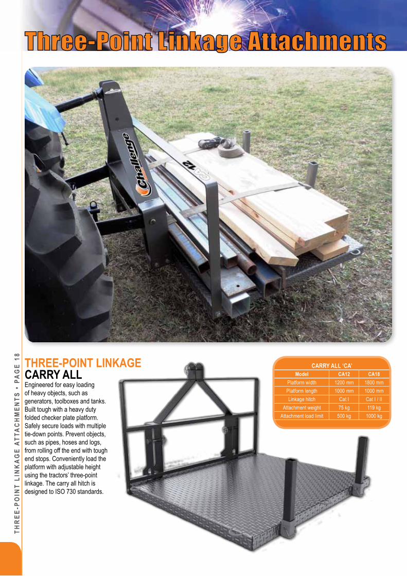
Carry aLL ‘Ca’Model CA12 CA18
Platform width 1200 mm 1800 mmPlatform length 1000 mm 1000 mmLinkage hitch Cat I Cat I / II
Attachment weight 75 kg 119 kgAttachment load limit 500 kg 1000 kg
THrEE-poinT LinKagECarry aLLEngineered for easy loading of heavy objects, such as generators, toolboxes and tanks. Built tough with a heavy duty folded checker plate platform. Safely secure loads with multiple tie-down points. Prevent objects, such as pipes, hoses and logs, from rolling off the end with tough end stops. Conveniently load the platform with adjustable height using the tractors’ three-point linkage. The carry all hitch is designed to ISO 730 standards.

THr
EE-poin
T LinK
ag
E aTTaC
Hm
EnTS • pa
gE 19
opTionaL pipE rEELModel ELWeight 130 kg
Maximum pipe reel OD 2300 mmMinimum pipe reel ID 740 mm
Maximum pipe reel width 475 mmMinimum pipe reel width 100 mm
Load Capacity 220 kg
opTionaL pipE LayErModel 50 63
Tractor horse power 100-350 hp 160-350 hpWeight 66 kg 68 kgWidth 110 mm 125 mm
Pipe size 25-50 mm with joiner 25-63 mm with joiner
rippEr ‘r’Model r 2/3
Tractor horse power 100-350 hpLinkage hitch Cat II / III / III QH
Weight 255 kgRip depth 600 mmTine width 50 mm
Cutting tip width 100 mm
r SErIES rippErThe ripper has been designed for tough Australian conditions and is used to; rip pipe channels, rip drainage channels, rip channels to plant trees and break up compacted soil.
opTionaL pipE LayErSave time by attaching the optional pipe
layer to the ripper. The pipe layer features; Nylon tapered rollers to efficiently guide
the pipe with minimum resistance and a removable back carriage for
access to the pipe while laying. Available in two sizes.
opTionaL pipE rEELReduce the labour of feeding pipe through the pipe layer by attaching an Easy Load reel to the ripper. The reel features; adjustable arms for easy loading of pipe coils, hydraulic lift to adjust the height from the tractor seat, and an adjustable friction brake for smooth uncoiling of the pipe.

THr
EE-p
oin
T Li
nK
ag
E aT
TaC
Hm
EnTS
• p
ag
E 20 ESSENTIAL SErIES
SMALL GrAdErThe ESS grader is unique to its’ range as the simplicity in design creates an ideal implement for the compact sized agricultural tractors with a Category I or II hitch. This grader comes in three blade widths to choose from; 1200 mm (4’), 1500 mm (5’) and 1800 mm (6’).
rEAr ENd GrAdEr ‘ESS’Model ESS12 ESS15 ESS18
Cutting width 1200 mm (4’) 1500 mm (5’) 1800 mm (6’)Tractor horse power Up to 65 hp Up to 65 hp Up to 65 hp
Linkage hitch Cat I Cat I / II Cat I / IIMould board height 370 mm 370 mm 370 mm
Weight 136 kg 150 kg 160 kgBlade angle 360° 360° 360°
Blade angle adjust Manual. Increments of 15°
Manual. Increments of 15°
Manual. Increments of 15°
Cutting edge1-piece wear
resistant steel with reversible edge
1-piece wear resistant steel with
reversible edge
1-piece wear resistant steel with
reversible edgeSupporting stands 1 1 1

THr
EE-poin
T LinK
ag
E aTTaC
Hm
EnTS • pa
gE 21
ESSENTIAL SErIESMEdIUM GrAdErCompatible with fixed or floating upper tractor hitch, the ESM grader is designed to suit agricultural tractors with 30 to 100 horse power, a Category I or II hitch and two sets of rear remotes available to operate the hydraulic blade adjustment features from the comfort of the tractor seat. This grader comes in two blade widths; 1600 mm (6’) and 2100 mm (7’).
ESSENTIAL SErIESLArGE GrAdEr
The ESL grader is designed to suit agricultural tractors with 60 to 120 horse power, a Category
II hitch and two sets of rear remotes available to operate the hydraulic blade adjustment
features from the comfort of the tractor seat. This grader comes in two blade widths; 2400 mm (8’) and 3000 mm (10’).
rEAr ENd GrAdEr ‘ESM’ & ‘ESL’Model ESM18 ESM21 ESL24 ESL30
Cutting width 1800 mm (6’) 2100 mm (7’) 2400 mm (8’) 3000 mm (10’)Tractor horse power 30-100 hp 30-100 hp 60-120 hp 60-120 hp
Linkage hitch Cat I / II Cat I / II Cat II Cat IIMould board height 450 mm 450 mm 500 mm 500 mm
Weight 369 kg 376 kg 525 kg 565 kgBlade offset Minimum 600 mm left/right Minimum 600 mm left/right Minimum 800 mm left/right Minimum 800 mm left/right
Blade offset adjust Standard with telescopic arm or optional hydraulics.
Standard with telescopic arm or optional hydraulics.
Standard with telescopic arm or optional hydraulics.
Standard with telescopic arm or optional hydraulics.
Blade angle ±45° ±45° ±45° ±45°Blade angle adjust Hydraulic Hydraulic Hydraulic Hydraulic
Blade tilt ±30° ±30° ±30° ±30°Blade tilt adjust Hydraulic Hydraulic Hydraulic Hydraulic
Cutting edge 1-piece wear resistant steel with reversible edge
1-piece wear resistant steel with reversible edge
1-piece wear resistant steel with reversible edge
1-piece wear resistant steel with reversible edge
Supporting stands 2 2 2 2Hungry boards Optional @ 30 kg Optional @ 30 kg Optional @ 35 kg Optional @ 35 kgDepth wheel Optional @ 45 kg Optional @ 45 kg Optional @ 50 kg Optional @ 50 kg
Depth wheel adjust Standard with ratchet ram or optional remote hydraulics.
Standard with ratchet ram or optional remote hydraulics.
Standard with ratchet ram or optional remote hydraulics.
Standard with ratchet ram or optional remote hydraulics.

THr
EE-p
oin
T Li
nK
ag
E aT
TaC
Hm
EnTS
• p
ag
E 22
The G Series graders can be used for maintenance and repair of agricultural roads and other farm related operations. The blade can also be reversed for back blade work.
The rear end graders have been designed specifically to suit tough Australian conditions.
• The large high tensile 100 mm rotation pin ensures correct alignment and maximum forces can be sustained.
• The main boom structure has been designed to handle the large horse power of todays tractors.
• The hydraulic hoses are clearly routed to the tractor remote connections.
•
• The graders are equipped with two heavy duty, pneumatic depth wheels.
• The blade angle and rotation plate is fixed by two large machined brackets that take all the forces submitted through the blade.
• The front hitch is compatible with category 2 and 3 linkage and category 3 quick hitch system.
• The grader blades are constructed of 8 mm high grade steel with replaceable purpose built toughened wear edges.
• This attachment also includes two heavy duty frame stands that allow stable and easy storage of the rear end grader.
G SErIESrEAr ENd GrAdEr
rEAr ENd GrAdEr ‘G’Model G24 G30
Tractor horse power 90-180 hp 120-220 hpLinkage hitch Cat II / III / III QH Cat II / III / III QHBlade width 2400 mm (8’) 3000 mm (10’)Blade height 600 mm (2’) 600 mm (2’)
Hydraulic blade angle Standard StandardBlade angle adjustment 45° 45°
Hydraulic blade tilt Standard StandardBlade tilt adjustment 18° 18°
Hydraulic blade offset Standard StandardBlade offset adjustment 830 mm (33”) 830 mm (33”)
Blade thickness 8 mm (5/16”) 8 mm (5/16”)Weight 1070 kg (2360 lbs) 1120 kg (2470 lbs)
Side panels Optional Optional100287
H


THr
EE-p
oin
T Li
nK
ag
E aT
TaC
Hm
EnTS
• p
ag
E 24
100190FULCRUM
Downward forceapplied by linkage
counterweight
Front axle loadreduced and
stability increased
A major safety factor in the operation of a front end loader/tractor unit is the stability of the machine whilst lifting and transporting a load.
After fitting a loader, the centre of gravity of the tractor is moved forward. When a load is raised, this combined centre of gravity is moved further forward and higher, potentially moving the centre of gravity outside the base triangle of the tractor, causing instability both longitudinally and laterally. Along with instability, there are high loads placed on tractor front-end components such as tyres, rims and axle.
Traditionally, tractor owners have added ballast to increase the stability of the tractor when a loader is fitted by adding liquid fill to the rear tyres, or fitting rear wheel weights.
Although the addition of liquid fill or rear wheel weights may aid stability, neither will reduce the high front axle load when using the front end loader on the tractor. Also, an unnecessarily large amount of weight is required
to achieve a result, increasing total vehicle mass considerably.
The three-point linkage counterweight is designed to enhance the performance of the tractor/loader combination by providing suitable ballast behind the rear axle. Applying weight on the three-point linkage of the tractor will provide the greatest counterbalancing effect as it applies a downward force behind the rear axle, reducing the weight carried by the front tyres, rims and axle. The three-point linkage counterweight will not only reduce the front axle load but will also move the centre of gravity of the tractor/loader combination rearwards, and lower, to maintain stability and ensure safe, effective performance.
The three-point linkage counterweights are supplied without ballast and should be filled with cement to achieve the designed operational weights. Each tractor and loader specification should be considered when selecting the appropriate counterweight.
COUNTErWEIGHT ‘CW’Model 14CW 30CW 49CW 125CW
Weight (empty) 45 kg 70 kg 175 kg 380 kg
Weight (full) 360 kg 760 kg 1220 kg 3270 kg
Width 560 mm 800 mm 1015 mm 1610 mm
Height 780 mm 800 mm 950 mm 1210 mm
Depth 480 mm 600 mm 630 mm 715 mm
Volume 0.14 m3 0.30 m3 0.49 m3 1.25 m3
Linkage hitch Cat I Cat I Cat II Cat III
Standard hitch Yes Yes Yes Yes
Quick hitch - - Yes Yes
Challenge Implements strongly recommends the use of a three-point linkage counterweight to improve both the safety and performance of your Challenge loader/tractor unit.
Challenge Implements has undergone an independent evaluation to ensure that the company complies with the Tractor & Machinery Association of Australia (TMA) code of practice for manufacture and supply of agricultural front end loaders.
Counterweight for low horse power tractors
THrEE-poinT LinKagE COUNTErWEIGHT

TELEHa
nD
LEr aTTa
CH
mEn
TS • pag
E 25
TELEHANdLEr LIGHT MATErIAL BUCkETThe telehandler range of buckets are available in three different widths for both Manitou and JCB hitch. These buckets are purposely designed for light material with a bulk density of up to 1200 kg / m³ allowing for large volumetric scoops. The light material buckets are designed with hard wearing cutting edge and side leading edges. The design caters for a bolt on hard wearing leading edge and a weld on rear wear pad to protect the underside of the bucket. The buckets have an optional level gauge.
TELEHANdLEr LArGE SqUArE BaLE SpiKEThe telehandler large square bale spike is designed to handle three large square bales in a single go; thereby reducing travel and operator time. The design features a collapsible back rest for the purposes of reducing transportation costs to the customer. The design also features a braced back rest that will ensure a very strong structure with maximum visibility.
TELEHANdLEr LIGHT MATErIAL BUCkETSModel TM-15LM TM-25LM TM-35LM TJ-15LM TJ-25LM TJ-35LMWidth 2100 mm 2400 mm 2400 mm 2100 mm 2400 mm 2400 mmHeight 1042 mm 1257 mm 1491 mm 1018 mm 1164 mm 1381 mmDepth 1264 mm 1494 mm 1734 mm 1429 mm 1612 mm 1888 mm
Rated Volume 1.5 m³ 2.5 m³ 3.5 m³ 1.5 m³ 2.5 m³ 3.5 m³Bolt-on Edge Yes Yes Yes Yes Yes Yes
Optional level gauge Yes Yes Yes Yes Yes YesWeight 485 kg 620 kg 775 kg 500 kg 630 kg 785 kg
Rated Material Density less than or equal to 1200 kg/m³ 1200 kg/m³ 1200 kg/m³ 1200 kg/m³ 1200 kg/m³ 1200 kg/m³
Level gauge
TELEHanDLEr LargE SqUarE BaLE SpiKE ‘BS’Model TM-19BS TJ-19BS
Hitch type Manitou JCBHeight 2075 mm 2075 mmWidth 1910 mm 1910 mmWeight 305 kg 305 kg
Tines x usable length 4 x 1110 mm (Conus II)
5 x 1110 mm (Conus II)
4 x 1110 mm (Conus II)
5 x 1110 mm (Conus II)
Inner tine spacing 900 mm 450 mm 900 mm 450 mmOuter tine spacing 450 mm 450 mm 450 mm 450 mm
Maximum lift 3 bales 3 balesTotal handling capacity 1800 kg 1800 kg

REF
. 980
0023
56 •
REV
. S •
21/0
1/19