attachment ii-7 - utah
TRANSCRIPT

ATTACHMENT II-7
CLOSURE PLAN

Attachment II-7 – Closure and Post-Closure Plan August 20, 2021Clean Harbors Grassy Mountain, LLC. Page i UTD991301748
TABLE OF CONTENTS
A. CLOSURE PLAN ..................................................................................................................11.0 INTRODUCTION .................................................................................................................12.0 FACILITY UNIT DESCRIPTIONS....................................................................................3
2.1 General Information.........................................................................................................32.2 Hazardous Waste Storage/Treatment/Process Units .......................................................3
3.0 PARTIAL FACILITY CLOSURE ACTIVITIES..............................................................54.0 MAXIMUM EXTENT OF OPERATIONS ........................................................................7
4.1 Management of Maximum Inventory..............................................................................75.0 FACILITY DECONTAMINATION ...................................................................................9
5.1 Contaminated Equipment, Structures and Facility Areas................................................95.2 Typical Decontamination Procedures..............................................................................95.3 Surface Impoundment Unit Decontamination ...............................................................14
6.0 CRITERIA FOR EVALUATING DECONTAMINATION ...........................................156.1 Closure of "Hard Surface" Waste Treatment or Containment Items.............................156.2 Decontamination Residuals Management .....................................................................166.3 Decontamination Standards ...........................................................................................17
7.0 CLOSURE CAPPING OF LANDFILL CELLS ..............................................................197.1 Final Cover System........................................................................................................197.2 Intent to Begin Closure..................................................................................................197.3 Design Engineering Report (DER)................................................................................19
8.0 GROUNDWATER MONITORING REQUIREMENTS................................................209.0 ANCILLARY CLOSURE ACTIVITIES ..........................................................................20
9.1 Leachate Management ...................................................................................................209.2 Run-On/Run-Off Control...............................................................................................219.3 Security/Inspection ........................................................................................................219.4 Final/Partial Closure Application for Plan Approval ....................................................22
10.0 SURVEY PLAT ...................................................................................................................2211.0 CLOSURE CERTIFICATION ..........................................................................................2212.0 COMPLETE UNIT AND FINAL FACILITY CLOSURE SCHEDULE ......................2213.0 CONTINGENT CLOSURE REQUIREMENTS..............................................................2314.0 FINANCIAL REQUIREMENTS FOR CLOSURE.........................................................23

Attachment II-7 – Closure and Post-Closure Plan August 20, 2021Clean Harbors Grassy Mountain, LLC. Page ii UTD991301748
14.1 Closure Cost Estimate Support Information..................................................................2414.2 Container Management Facility Closure Cost Worksheets...........................................2414.3 Drain & Flush Building Warehouse One Closure Cost Worksheets .............................2414.4 Site-Wide Closure Cost Estimate Support Information.................................................24
B. POST-CLOSURE PLAN ....................................................................................................2515.0 INTRODUCTION ...............................................................................................................2516.0 FACILITY POST-CLOSURE REQUIREMENTS..........................................................25
16.1 Affected Hazardous Waste Management Units.............................................................2516.2 Monitoring and Maintenance Activities ........................................................................26
17.0 FINANCIAL REQUIREMENTS FOR POST-CLOSURE .............................................2917.1 Post-Closure Care Cost Estimates .................................................................................29
C. FINANCIAL ASSURANCE MECHANISM ....................................................................3018.0 FINANCIAL ASSURANCES.............................................................................................30
18.1 Financial Assurance for Closure....................................................................................3018.2 Financial Assurances for Post-Closure..........................................................................3018.3 Liability Requirements ..................................................................................................31
D. PCB COMMERCIAL STORAGE CLOSURE COST ESTIMATE ..............................3219.0 ANNUAL REVIEW OF INITIAL COST ESTIMATE ...................................................3220.0 CLOSURE COST ESTIMATE..........................................................................................32
20.1 Tank Farm......................................................................................................................3220.2 Container Storage Areas ................................................................................................3320.3 Auxiliary Equipment .....................................................................................................3320.4 Administrative and Supervisor Costs ............................................................................3320.5 Closure Certification......................................................................................................3320.6 Total Estimated Landfill Capacity Assurance (in cubic yards) .....................................3320.7 Total Estimated Closure Cost ........................................................................................34
21.0 REVIEW AND ADJUSTMENT OF COST ESTIMATE................................................3422.0 CLOSURE PLAN ................................................................................................................34
22.1 Facility Description .......................................................................................................3422.2 Disposal of PCB Waste Inventory.................................................................................4322.3 Closure Plan Sampling, Decontamination.....................................................................4622.4 Other Closure Activities ................................................................................................5322.5 Schedule for Closure......................................................................................................54
Attachment II-7 – Closure and Post-Closure Plan August 20, 2021Clean Harbors Grassy Mountain, LLC. Page iii UTD991301748
22.6 Modification to Closure Plans .......................................................................................54E. CLOSURE AND POST-CLOSURE PLAN FOR RCRA/TSCA CELLS ......................5423.0 CLOSURE CAP LAYOUT AND GENERAL DESCRIPTION .....................................5424.0 DESIGN................................................................................................................................5525.0 CLOSURE ACTIONS.........................................................................................................56
25.1 Preparation of the Waste Mound ...................................................................................5625.2 Compacted Clay or Geosynthetic Clay Liner (GCL) ....................................................5725.3 HDPE Liner ...................................................................................................................5725.4 Drainage net and Geotextile Filter Fabric (or Geocomposite) ......................................5725.5 Protective Cover ............................................................................................................5725.6 Erosion Protective Cover ...............................................................................................5725.7 Schedule of Events ........................................................................................................5825.8 Closure Cost Estimates ..................................................................................................58
26.0 Post-Closure Care Plan .......................................................................................................5826.1 Notice to Local Land Authority.....................................................................................60
27.0 Post-Closure Cost Estimate ................................................................................................6027.1 Annual Update of the Closure/Post-Closure Cost Estimate ..........................................60
28.0 Financial assurance mechanism .........................................................................................6128.1 Financial Assurance for Closure....................................................................................6128.2 Financial Assurances for Post-Closure..........................................................................6128.3 Liability Requirements ..................................................................................................62
29.0 Soil Sampling Plan...............................................................................................................6229.1 Quality Assurance and Quality Control - Soil Sampling Plan ......................................6329.2 Analytical Procedures ....................................................................................................6429.3 Replicate Samples..........................................................................................................6429.4 Blanks ............................................................................................................................6429.5 Field Blanks ...................................................................................................................6429.6 Chain-of-Custody ..........................................................................................................65

Attachment II-7 – Closure and Post-Closure Plan August 20, 2021Clean Harbors Grassy Mountain, LLC. Page iv UTD991301748
LIST OF APPENDICES AND TABLES
Appendix A: Closure/Post-Closure Inventory, Standards, and Reference Tables
RCRA Facility
Table A.1 : Container Management Facility, Leachate Tanks, Leachate Building, Bulk Solids Storage Area, and Stabilization Tanks Maximum Inventory at Time of Closure
Table A.2 : On-Site Management – Landfill Disposal - Closure Waste Inventory - Decontamination Residue Quantity Estimates
Table A.3 : Facility Roadways – Dimensions and Volumes Based on TypeTable A.4 : ReservedTable A.5 : List of Existing and Proposed Disposal Units and Surface Impoundments and the
Number of Existing and Proposed Associated Groundwater Monitoring WellsTable A.6 : Site Wide Closure Schedule (Elapsed Time in Months)
PCB Commercial Storage Facility
Table A.7 : TSCA Total Estimated Landfill Capacity Assurance (in cubic yards)Table A.8 : Leachate Pumping Rates and FrequenciesTable A.9 : DFBWO Containment CapacitiesTable A.10 : Bulk Tank Descriptions DFBWO, Area BTable A.11 : Bulk Tank Description – Tank FarmTable A.12 : Tank Farm Containment CapacitiesTable A.13 : Estimate of PCB Waste Type PercentagesTable A.14 : DFBWO Waste CapacitiesTable A.15 : Disposal Facilities for PCB MaterialsTable A.16 : Auxiliary EquipmentTable A.17 : Anticipated Closure ScheduleTable A.18 : Numerical Standards for PCB Decontamination
RCRA/TSCA Facility
Table A.19 : Anticipated Closure Schedule for RCRA/TSCA CellsTable A.20 : Post-Closure Leachate Pumping and Quantifying FrequencyTable A.21 : Post-Closure Leachate Sampling Frequency
Attachment II-7 – Closure and Post-Closure Plan August 20, 2021Clean Harbors Grassy Mountain, LLC. Page v UTD991301748
Appendix B: Closure/Post-Closure Cost Summary Tables
RCRA Facility
Table B.1 : Container Management Facility and BSSA Closure Cost EstimateTable B.2 : Total Site-Wide Facility Closure Cost EstimatesTable B.3 : Post-Closure Care Cost Estimate Summary
PCB Commercial Storage Facility
Table B.4 : Tank Farm Estimated Closure Cost and Required Disposal CapacityTable B.5 : Container Storage Area Estimated Closure Cost and Table B.6 : Required Disposal CapacityTable B.7 : PCB Commercial Storage Facilities Total Estimated Closure Cost
RCRA/TSCA Facility
Table C.1 : Summary of Closure/Post-Closure Costs for RCRA/TSCA Cells
Appendix C: Closure/Post-Closure Cost Worksheets
RCRA Facility Worksheets
Table C.2 : Worksheet CMF-1: Inventory ManagementTable C.3 : Worksheet CMF-2: Facility DecontaminationTable C.4 : Worksheet CMF-3: Ancillary Closure ActivitiesTable C.5 : Worksheet CMF-4: Closure CertificationTable C.6 : Worksheet CLO-1: Inventory Management of Hazardous Waste
Treatment/Storage/Process UnitsTable C.7 : Worksheet CLO-2: Hazardous Waste Management Unit (HWMU)
DecontaminationTable C.8 : Worksheet CLO-3: Treatment and Disposal of Decontamination ResidualsTable C.9 : Worksheet CLO-4: Final Cover/Landfill ClosureTable C.10 : Worksheet CLO-5: Groundwater Monitoring During Closure ActivitiesTable C.11 : Worksheet CLO-6: Ancillary Closure ActivitiesTable C.12 : Worksheet CLO-7: Closure Certification
PCB Commercial Storage Facility Worksheets
Table C.13 : Worksheet TCLO-1: PCB Oil (TSCA) and Used Oil (RCRA) Disposal ChargesTable C.14 : Worksheet TCLO-2: Bulk Tank DisposalTable C.15 : Worksheet TCLO-3: Area Decontamination – Concrete Removal
Attachment II-7 – Closure and Post-Closure Plan August 20, 2021Clean Harbors Grassy Mountain, LLC. Page vi UTD991301748
Table C.16 : Worksheet TCLO-4: Underground Pipeline RemovalTable C.17 : Worksheet TCLO -5: Container Inventory RemovalTable C.18 : Worksheet TCLO -6: Transformer Flush and Bulk Tank DisposalTable C.19 : Worksheet TCLO -7: Area Decontamination and Concrete RemovalTable C.20 : Worksheet TCLO -8: Auxiliary Equipment DisposalTable C.21 : Worksheet TCLO -9: Administrative and Supervisor CostsTable C.22 : Worksheet TCLO -10: Closure Certification
RCRA/TSCA Facility Worksheets
Table C.23 : Worksheet RTCLO-1: Estimated RCRA/TSCA Cell Closure CostsTable C.24 : Worksheet RTCLO-2: Groundwater & Leachate Monitoring Costs During
Closure ActivitiesTable C.25 : Worksheet RTCLO-3: Closure Maintenance ActivitiesTable C.26 : Worksheet RTCLO-4: Leachate Collection, Treatment, Storage and DisposalTable C.27 : Worksheet RTPCLO-1: Post-Closure Ancillary CostsTable C.28 : Worksheet RTPCLO-2: Post-Closure Leachate Collection, Treatment, Storage
and Disposal
Appendix D: Cost Documentation Appendix (CDA)
Table D.1 : Cost Documentation (CDA): Inventory ManagementTable D.2 : Cost Documentation (CDA): Landfill Capacity AssuranceTable D.3 : Cost Documentation (CDA): Hazardous Waste Management Unit (HWMU)
Decontamination and Disposal of Decontamination ResiduesTable D.4 : Cost Documentation (CDA): Final Cover and Landfill ClosureTable D.5 : Cost Documentation (CDA): Groundwater Monitoring During
Closure/Post-ClosureTable D.6 : Cost Documentation (CDA): Ancillary Closure ActivitiesTable D.7 : Cost Documentation (CDA): Closure CertificationTable D.8 : Cost Documentation (CDA): Post-Closure Cost ConsiderationsTable D.9 : Cost Documentation (CDA): Annual Post-Closure Certification and
AdministrationTable D.10 : Cost Documentation (CDA): Landfill Cell Closure Quantity EstimatesTable D.11 : Cost Documentation (CDA): Landfill Cell Closure Costs

Attachment II-7 – Closure and Post-Closure Plan August 20, 2021Clean Harbors Grassy Mountain, LLC. Page 1 UTD991301748
A. CLOSURE PLAN
1.0 INTRODUCTION
This closure plan is set forth to comply with the applicable requirements of the following regulations and methods:
A. Utah Admin. Code R315-261-Identification and Listing of Hazardous Waste
Appendix VII – Basis for Listing Hazardous Waste Appendix VIII – Hazardous Constituents
B. Utah Admin. Code R315-262-Standards Applicable to Generators of Hazardous Waste
Subpart A (262.11) – Hazardous Waste Determination and Recordkeeping
C. For RCRA Facilities: 40 CFR 264–Standards for Owners and Operators of Hazardous Waste Treatment, Storage, and Disposal Facilities
Utah Admin. Code R315-264-110 through 120) - Closure and Post-Closure Utah Admin. Code R315-264-140 through 151) - Financial Requirements Utah Admin. Code R315-264-170 through 179) – Use and Management of Containers;
Specifically, 264.178 - Closure Utah Admin. Code R315-264-190 through 200) – Tank Systems; Specifically, 264.197 –
Closure and Post-Closure Care Utah Admin. Code R315-264-220 through 231) – Surface Impoundments; Specifically,
264.228 – Closure and Post-Closure Care Utah Admin. Code R315-264-300 through 317) – Landfills; Specifically, 264.310 –
Closure and Post-Closure Care, and 264.313 – Special Requirements for Incompatible Wastes
D. Utah Admin. Code R315-268-Land Disposal Restrictions
Subpart D (268.45) – Treatment Standards for Hazardous Debris
E. For TSCA Facilities: 40 CFR 761-Polychlorinated Biphenyls (PCBs Manufacturing, Processing, Distribution in Commerce, and Use Prohibitions
Subpart C (761.40-45) – Marking of PCBs and PCB Items Subpart D (761.50-79) – Storage and Disposal Subpart G (761.120-135) – PCB Spill Cleanup Policy Subpart J (761.780-193) – General Records and Reports Subpart K (761.202-219) – PCB Waste Disposal Records and Reports Subpart N (761.260-274) – Cleanup Site Characterization Sampling for PCB
Remediation Waste in Accordance with 761.61(a)(2)

Attachment II-7 – Closure and Post-Closure Plan August 20, 2021Clean Harbors Grassy Mountain, LLC. Page 2 UTD991301748
Subpart N (761.260-274) – Cleanup Site Characterization Sampling for PCB Remediation Waste in Accordance with §761.61(a)(2)
Subpart O (761.280-298) – Sampling to Verify Completion of Self-Implementing Cleanup and On-Site Disposal of Bulk PCB Remediation Waste and Porous Surfaces in Accordance With §761.61(a)(6)
Subpart P (761.300-316) – Sampling Non-Porous Surfaces for Measurement-Based Use, Reuse, and On-Site or Off-Site Disposal Under §761.61(a)(6) and Decontamination Under §761.79(b)(3)
Subpart Q (761.320-326) – Self-Implementing Alternative Extraction and Chemical Analysis Procedures for Non-liquid PCB Remediation Waste Samples
Subpart R (761.340-359) – Sampling Non-Liquid, Non-Metal PCB Bulk Product Waste for Purposes of Characterization for PCB Disposal in Accordance With §761.62, and Sampling PCB Remediation Waste Destined for Off-Site Disposal, in Accordance With §761.61
Subpart S (761.360-378) – Double Wash/Rinse Method for Decontaminating Non-Porous Surfaces
Appendix IX – Ground-Water Monitoring List
F. EPA Publications
EPA SW-846 – Test Methods for Evaluating Solid Waste
The contents apply to the Grassy Mountain facility (GM), EPA ID# UTD991301748 to reflect the most current approved permit and facility operations. Detailed descriptions of the relevant units/areas are provided in the specific modules as referenced herein to the permit. Only general descriptions are provided within this plan. Specific closure plan information is identified for each individual unit and/or process area, within the overall facility, as appropriate. This information may be referenced as necessary to provide a comprehensive closure plan, which meets the stated regulatory requirements.
In compliance with applicable regulations, this plan sets forth the necessary actions and requirements to close GM in a manner that minimizes the need for further maintenance and controls, minimizes or eliminates, to the extent necessary to protect human health and the environment, post-closure escape of hazardous waste, hazardous constituents, leachate, contaminated run-off, or hazardous waste decomposition products to the ground or surface waters, or to the atmosphere.
To facilitate the development of a closure cost estimate for the entire facility, a sequence of closing the current waste management units is presented. However, the actual sequence of unit closures may be different than what is presented. The sequence of closing a unit in this plan is based on minimizing potential exposure of personnel to contaminants and the potential of releasing contaminants to the environment. It is less likely that this sequence will vary from that presented, but it is possible based on circumstances at the time of closure. The plan assumes maximum inventory levels by waste type and provides procedures for disposing of that inventory, for decontaminating and/or disposing of equipment and containment systems and for

Attachment II-7 – Closure and Post-Closure Plan August 20, 2021Clean Harbors Grassy Mountain, LLC. Page 3 UTD991301748
obtaining closure certification. The cost estimate assumes the use of third parties to perform all closure work.
All tables referenced in this plan are presented in the attached appendices. Appendix A provides closure/post-closure inventories, standards, and reference tables. Appendix B provides closure/post closure cost summary tables. Appendix C provides closure/post closure cost worksheets. Appendix D is the cost documentation appendix (CDA) that provides tables of unit and other specific costs used for cost analysis.
2.0 FACILITY UNIT DESCRIPTIONS
2.1 GENERAL INFORMATION
2.1.1 Location
The Grassy Mountain facility is located approximately 83 miles west of Salt Lake City, Utah in Section 16 of Township 1 North, Range 12 West in Tooele County, Utah. The active site, that portion of the property used for active and closed waste management units, is located inside a fence, and comprises most of this section. The waste management units are permitted for treatment, storage, and disposal of hazardous waste pursuant to the regulations administered by the State of Utah and/or the United States Environmental Protection Agency. Attachment II-1 contains a site plan that shows locations of the various waste management units and the fenced portion of the section. In addition, the facility owns a ½ mile buffer around all of Section 16.
2.1.2 General Hydrogeologic Conditions
The facility is located upon exposed sediments of ancient Lake Bonneville. This geologic formation is a silty clay deposit believed to be up to 10,000 feet thick. It contains no potable water and subsurface water movement is extremely slow. The sediments underlying the site have a range in hydraulic conductivity of 1 x 10⁻⁴ to 10-6 cm/sec and extremely high sodium concentrations. Subsurface water contains total dissolved solids concentrations of 50,000 to 100,000 mg/l. The region receives approximately 6 inches of precipitation annually with evaporation rates of over 40 inches per year. There are no rivers or streams within 20 miles of the facility and the nearest body of water is the Great Salt Lake (30 miles northeast).
2.2 HAZARDOUS WASTE STORAGE/TREATMENT/PROCESS UNITS
The following sections provide a description of the currently permitted hazardous waste management units and facilities subject to closure. The descriptions provide an accounting of units and containments which are covered by this closure and post-closure plan, so that future and pending modifications may be clearly delineated. More detailed unit information is provided within referenced permit modules for each unit at the facility.
2.2.1 Container Management Facility (Module III)
The Container Management Facility (CMF) is an elevated slab, pre-engineered steel roof and side wall structure. Physical features of the structure prevent escape of contaminants should spills or leaks occur and protect the unit from weather and precipitation while the containerized

Attachment II-7 – Closure and Post-Closure Plan August 20, 2021Clean Harbors Grassy Mountain, LLC. Page 4 UTD991301748
waste material is being managed prior to disposal. The unit has separated drainage areas provided by concrete containment curbing, sumps for containment, and ramps for access. The slab and sump structures are constructed with waste compatible joint materials and water stops to prevent intrusion by waste into the structural unit, as well as leakage through the unit to underlying soils. Specific details about the CMF, including the capacity of the facility, are provided in Table A.1.
Dock 1 and Storage Pads 2 and 3 are utilized to store all wastes accepted at the facility, including wastes not subject to regulation under Subtitle C of RCRA.
2.2.2 Drain and Flush Building Warehouse One - DFBWO (Module III)
The Drain and Flush Building Warehouse One (DFBWO) is an elevated slab, pre-engineered steel roof and side wall structure. Physical features of the structure prevent escape of contaminants should spills or leaks occur and protect the unit from weather and precipitation while the containerized waste material is being managed prior to disposal. The unit has separated drainage areas provided by concrete containment curbing, sumps for containment, and ramps for access. The slab and sump structures are constructed with waste compatible joint materials and water stops to prevent intrusion by waste into the structural unit, as well as leakage through the unit to underlying soils.
2.2.3 Facility Tanks
Specific details about the tanks discussed in this section are contained in Table A, "Existing Tanks, Information Summary". Facility Tanks Include:
Stabilization Tanks Leachate Storage Tanks
Some of the tanks have ancillary pipes and valves, and other tank equipment. All are located within secondary containment. Secondary containment areas are comprised of concrete slabs with containment curbing, sumps for collection/containment of run-off from selected portions of the units and secondary containment/leak detection in tank areas. All floor slabs, containment and sump structures are constructed with waste compatible joint materials and water stops to prevent intrusion by waste into the structural unit, as well as leakage through the unit to underlying soils.
2.2.3.1 Waste Stabilization Facility
The Waste Stabilization Facility consists of open-top, square tanks, in which reagents are mixed with the wastes, typically using a backhoe/track hoe type device. Since the tanks are not storage units, there is no inventory of wastes associated with these units. The facility containment areas include open tank treatment units and secondary containment, transport vehicle unloading areas, treated waste haul vehicle staging areas and ramps for access.
Waste Stabilization Tanks 122-TN-001, 122-TN-002, 122-TN-003
Attachment II-7 – Closure and Post-Closure Plan August 20, 2021Clean Harbors Grassy Mountain, LLC. Page 5 UTD991301748
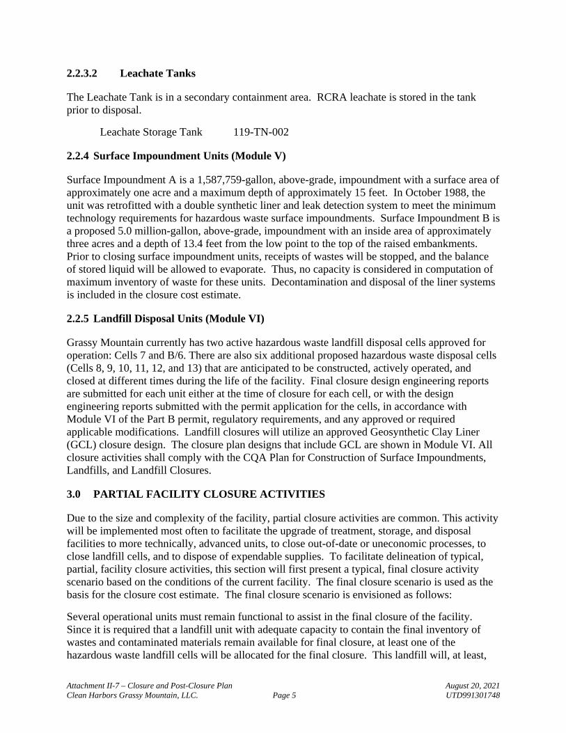
2.2.3.2 Leachate Tanks
The Leachate Tank is in a secondary containment area. RCRA leachate is stored in the tank prior to disposal.
Leachate Storage Tank 119-TN-002
2.2.4 Surface Impoundment Units (Module V)
Surface Impoundment A is a 1,587,759-gallon, above-grade, impoundment with a surface area of approximately one acre and a maximum depth of approximately 15 feet. In October 1988, the unit was retrofitted with a double synthetic liner and leak detection system to meet the minimum technology requirements for hazardous waste surface impoundments. Surface Impoundment B is a proposed 5.0 million-gallon, above-grade, impoundment with an inside area of approximately three acres and a depth of 13.4 feet from the low point to the top of the raised embankments. Prior to closing surface impoundment units, receipts of wastes will be stopped, and the balance of stored liquid will be allowed to evaporate. Thus, no capacity is considered in computation of maximum inventory of waste for these units. Decontamination and disposal of the liner systems is included in the closure cost estimate.
2.2.5 Landfill Disposal Units (Module VI)
Grassy Mountain currently has two active hazardous waste landfill disposal cells approved for operation: Cells 7 and B/6. There are also six additional proposed hazardous waste disposal cells (Cells 8, 9, 10, 11, 12, and 13) that are anticipated to be constructed, actively operated, and closed at different times during the life of the facility. Final closure design engineering reports are submitted for each unit either at the time of closure for each cell, or with the design engineering reports submitted with the permit application for the cells, in accordance with Module VI of the Part B permit, regulatory requirements, and any approved or required applicable modifications. Landfill closures will utilize an approved Geosynthetic Clay Liner (GCL) closure design. The closure plan designs that include GCL are shown in Module VI. All closure activities shall comply with the CQA Plan for Construction of Surface Impoundments, Landfills, and Landfill Closures.
3.0 PARTIAL FACILITY CLOSURE ACTIVITIES
Due to the size and complexity of the facility, partial closure activities are common. This activity will be implemented most often to facilitate the upgrade of treatment, storage, and disposal facilities to more technically, advanced units, to close out-of-date or uneconomic processes, to close landfill cells, and to dispose of expendable supplies. To facilitate delineation of typical, partial, facility closure activities, this section will first present a typical, final closure activity scenario based on the conditions of the current facility. The final closure scenario is used as the basis for the closure cost estimate. The final closure scenario is envisioned as follows:
Several operational units must remain functional to assist in the final closure of the facility. Since it is required that a landfill unit with adequate capacity to contain the final inventory of wastes and contaminated materials remain available for final closure, at least one of the hazardous waste landfill cells will be allocated for the final closure. This landfill will, at least,
Attachment II-7 – Closure and Post-Closure Plan August 20, 2021Clean Harbors Grassy Mountain, LLC. Page 6 UTD991301748
have available the volume listed in Table A.2 for compliance with Landfill Capacity Assurance requirements. The Leachate Storage Tanks will be required to store the landfill leachate liquid prior to shipping it for disposal during final closure and through post closures of the facility. It is expected that the CMF and the stabilization system will remain operational until just before final closure of the last open landfill. These will remain open to ensure the proper handling of remaining wastes and waste residues, in accordance with regulations at the time of closure.
Other final closure activities include site monitoring, routine site inspections, groundwater monitoring, decontamination of equipment, structures and areas, and verification sampling and analytical efforts. A summary of the major facility process areas or portions thereof, which likely will remain operational until final closure, follows:
Hazardous Waste Landfill Cell Leachate Storage Tanks Stabilization Treatment Tank System CMF
Utilizing this information, all other facility units and/or process areas, or portions of those listed above, may be subject to the partial closure scenario. Each of the major facility process areas have been evaluated for this possibility and specific tasks within this site-wide closure plan, have set forth the necessary elements of partial closure within the requirements of the regulations. Each process area's closure activities meet the regulatory requirements for final closure except for notification and certification requirements for tanks and container storage areas. Notification and certification of closure of these non-disposal units is not required until final closure in accordance with current regulations. If, however, certification of a closed area under partial closure is made, it will not have to be certified again at the time of facility closure. Candidates for partial closure based on current facility operations include but are not limited to:
Portions of the CMF and DFBWO Facilities Portions of the Vat Stabilization Tank System Leachate Storage Tank Surface Impoundment Units Individual Hazardous Waste Landfill Cells
Partial closure includes discontinuance of use, removal of wastes and residues, and cleaning the unit, apparatus or area, as applicable, with or without filing for notification or certification of final closure. If certification is not received at partial closure, it will be required at final closure. Partial closure of any unit may take place at any time.
Equipment after decontamination may, at the discretion of the owner or operator, remain in place or may be removed. If an item cannot be decontaminated it must be removed for disposal. If an item cannot be decontaminated in place, it will be removed and either disposed or decontaminated in a fixed or temporary containment area. Equipment will not be left in place after the end of the post-closure period.

Attachment II-7 – Closure and Post-Closure Plan August 20, 2021Clean Harbors Grassy Mountain, LLC. Page 7 UTD991301748
4.0 MAXIMUM EXTENT OF OPERATIONS
This closure plan delineates the maximum extent of operations of the current facility. This is utilized as a “worst case" scenario for unexpected closure at any time during the facilities operation.
4.1 MANAGEMENT OF MAXIMUM INVENTORY
The information provided in Table A.1 describes the capacity of each container, tank, and storage unit/area considered at the maximum extent of operations for the facility at any given time during the permit period. Capacity information is used to reasonably quantify the inventory for removal, treatment, transport and/or disposal, as appropriate, at the time of closure. An estimate of residual waste generated during closure procedures (e.g., decontamination of units and soils and residue clean-up from routine operations/treatment) is provided based on the facility decontamination portion of the closure plan. Remaining waste inventory and decontamination residuals are two categories of potentially hazardous wastes to be managed during facility closure.
4.1.1 Estimate of Maximum Remaining Waste Inventory
No waste inventory is attributable to the open landfill cells since such cells would be receiving wastes for disposal - not generating wastes from closure of the units. Liquids that may be present in the surface impoundment at the time of final closure are assumed to be evaporated prior to closure. Therefore, no costs are associated with management of the potential surface impoundment inventory.
The potential maximum inventory of wastes contained in Table A.1 is assumed to be the amount in storage at the time of closure. Assumed maximum waste inventory at the time of closure is based strictly on the capacity of the CMF, and capacities of current, active, tank systems.
4.1.1.1 Maximum Inventory Management - Container Management Facility
Most Containerized Wastes will be disposed in an on-site landfill after any necessary or required treatment or amendment activities are performed. Up to 50 55-gallon drums of flammable waste will be sent off site for incineration. Any handling and processing of this containerized inventory will be performed in accordance with the current permit conditions and applicable regulations at the time of closure.
4.1.1.2 Maximum Inventory Management - Drain & Flush Building Warehouse One
Mercury containerized waste will be handled according to 4.1.3.3 - Off-Site Management as outlined in this section.
4.1.1.3 Maximum Inventory Management – Inactive and Active Tank Systems
Stabilization tanks are not used for storage so there is no associated waste inventory. No waste is considered in inventory for listed, inactive tanks that have been previously emptied and cleaned as described within this plan. The leachate tank will be needed through post-closure and thus

Attachment II-7 – Closure and Post-Closure Plan August 20, 2021Clean Harbors Grassy Mountain, LLC. Page 8 UTD991301748
will not be closed until the end of the post-closure period. The total permitted volume is considered to be disposed, however, for closure cost estimate purposes. The tank capacities for the computations of inventory have been taken from Module IV of this permit (stabilization tanks are only listed for completeness).
4.1.2 Estimate of Closure - Generated Residual Waste Inventory
Table A.2 summarizes the estimates of closure-generated residual waste as necessary to quantify closure management costs. Estimates are based on the decontamination methods and practices anticipated to be employed for the various units and are categorized according to the final management anticipated. The table provides a summary of the details presented in Appendix D, “Cost Documentation Appendix (CDA)," and the closure cost “Worksheets” in Appendix C. The table outlines estimated landfill capacity assurance quantities, as required.
4.1.3 Procedures for Handling Hazardous Waste Inventory and Decontamination Residues
This section presents a general discussion of typical management activities for the waste streams expected to comprise the inventory. Specific procedures related to a particular unit are included in the detailed closure cost estimates included in Appendix C and in Appendix D. Specific waste streams and any ancillary handling requirements such as removal, containerization and transportation, are included in the cost estimates as required for financial assurance.
4.1.3.1 RCRA/TSCA Waste Stream Inventory Management
It should be noted that less than 5% of the total waste inventory of the Container Management Building may be RCRA/TSCA combination waste materials. These materials will not materially affect the cost of disposal of inventory as they will either be calculated into the landfillable volume or into the incinerable volume as the closure plan exists today.
4.1.3.2 On-Site Management
In general, management activities related to the hazardous waste inventory will be handled on-site. As an example, the current facility has the capability of performing such activities as: containerization and re-containerization of wastes as necessary, off-site shipment of non-landfillable wastes, stabilization of residues and (inventory) waste streams, hazardous waste landfill disposal, providing and using container handling equipment and facilities, and mobilization of other equipment, as necessary. These management activities reflect a continuation of current, routine, operating practices at the site.
4.1.3.3 Off-Site Management
The off-site management practices expected for closure are the manifesting and loading of wastes destined for incineration or other suitable organic waste management practices, and disposal of leachate and decontamination liquids.
Attachment II-7 – Closure and Post-Closure Plan August 20, 2021Clean Harbors Grassy Mountain, LLC. Page 9 UTD991301748
5.0 FACILITY DECONTAMINATION
General facility areas subject to processing hazardous waste will receive a final evaluation of the necessity for decontamination. In addition, this section includes the decontamination of areas such as roads, staging areas, scale areas, laboratory, truck/wheel wash units, etc.
This section presents a discussion of typical decontamination procedures for all operational areas/units. The criteria, procedures and methods of decontamination presented below are typical in nature and will have Director approval should Clean Harbors modify the procedures described. Individual circumstances at the time of closure may require optional approaches to typical decontamination efforts listed below. The closure standards are performance based and thus specifying the exact method of achieving decontamination is not provided. However, the typical methods described have been used to develop the closure cost estimate.
Implementation of Module VIII will, for any portion of the facility at the time of partial closure of a unit or area or total closure of the facility, take precedence over the decontamination procedures described in this closure plan and will, when completed, meet closure requirements.
5.1 CONTAMINATED EQUIPMENT, STRUCTURES AND FACILITY AREAS
The contaminated equipment, structures and other areas to be decontaminated are: the Stabilization Tanks, Leachate Treatment Tanks, Leachate Building and the Container Management Building, and the DFBWO.
The container management containment surfaces will be assumed to be contaminated. Storage tanks listed in Table A.1 are considered contaminated even if they are in a clean condition after being placed on an inactive status. Surface impoundments will also require cleaning as part of closure. Details for each specific unit/process area component are considered below and delineated further on the closure cost estimate Worksheets (CMF and CLO) in Appendix C and Cost Documentation (CDA) in Appendix D. Final Closure Costs based on the listed criteria and assumptions are discussed in Section 14 and are presented in Appendix C.
5.2 TYPICAL DECONTAMINATION PROCEDURES
5.2.1 Remove Waste Inventory
The waste inventory will be processed and/or treated in accordance with current regulations, the procedures outlined in the permit and/or Waste Analysis Plan. As noted previously, RCRA/TSCA combination waste streams will not alter the combination of waste types or disposal methods already in place in this RCRA Closure Plan.
5.2.2 Inspection of Areas/Equipment
1. Inspect slab areas, tanks, ancillary process equipment, liquid transfer lines, sump structures and secondary containment areas for spills or evidence of spills, leaks, cracks, or other evidence of potential release of contaminants to the environment and document the findings.

Attachment II-7 – Closure and Post-Closure Plan August 20, 2021Clean Harbors Grassy Mountain, LLC. Page 10 UTD991301748
2. Remove any accumulated materials, i.e., dust, dirt, etc., that would inhibit recognition of spills or releases during the decontamination process.
3. Inspect containment surfaces for cracks, holes, or evidence of potential leakage or loss of integrity.
4. If cracks, holes, or evidence of potential leakage is documented, a core will be taken at the point(s) where integrity is questioned, through the concrete and no less than one foot into the soil beneath. Samples will be taken from 0-4 inches of depth, 5-8 inches of depth and 9-12 inches of depth. The samples will be analyzed for the constituents found in Utah Admin. Code R315-261 Appendix VIII.
5. Identify, record, and enter into the operating record the location of damage which could have caused the loss of integrity of the containment system if leakage is quantified during the test and use this information to accomplish step 5.2.6.3 after decontamination of the containment surfaces.
6. Repair any cracks or other damage to containment surfaces that could release waste waters to the ground during decontamination efforts.
5.2.3 Decontamination of Areas/Equipment
1. Decontamination of tanks and/or piping in place or remove them to fixed or temporary containment for decontamination utilizing decontamination methods for hard surfaces.
2. Decontaminate tanks and equipment inside and out.3. Remove equipment from containment as necessary to ensure the containment surfaces are
properly decontaminated.4. Dispose of tanks and equipment in lieu of decontaminating them.
5.2.4 Decontaminate Structures
Decontaminate structures removing all stains (chemical stains do not have to be removed) utilizing decontamination methods for hard surfaces (6.1).
5.2.5 Decontaminate Secondary Containment Surfaces
Decontaminate secondary containment surfaces utilizing decontamination methods for hard surfaces.
5.2.6 Re-Inspect
Re-inspect all sump areas, secondary containment and leak detection systems for cracks, holes, or evidence of potential leakage or loss of integrity that was not identified prior to initiation of closure:
1. Collect core samples of the concrete and soil in order to identify the presence of contamination of the subsoils. If contamination is confirmed, go to step 5.2.6(2) and 5.2.6(3), and then proceed with Section 5.2.7.

Attachment II-7 – Closure and Post-Closure Plan August 20, 2021Clean Harbors Grassy Mountain, LLC. Page 11 UTD991301748
2. Remove all concrete and soil within six inches of the crack and dispose of it as contaminated.
3. Sample the soil from the trench left after removing the concrete and analyze for volatile, semi-volatile and pesticide/herbicide parameters provided in the Ground-Water Monitoring List found in Utah Admin. Code R315- 264-1107 (40 CFR 264 Appendix IX by reference). Continue expanding the trench both laterally and vertically until the analyses of the samples come back less than or equal to the concentrations listed and dispose of the removed soil according to the Waste Analysis Plan.
5.2.7 Soils Adjacent to the Unit
This section applies to soils immediately adjacent to the units within six (6) feet [or ten (10) feet in the case of the CMF of the outside of the containment areas and in areas where trucks or other equipment had been staged for storage or transfer of wastes.
1. Inspect the area and map the location of stained or discolored soils, 2. Remove the top six (6) inches of exposed soils, and 3. Take a grab sample of the excavated soil from each excavated area and analyze it for
volatile, semi-volatile and pesticide/herbicide parameters provided in the Ground-Water Monitoring and for PCBs from the current SW-846 method and the standards identified in Section 6.3 of this Closure Plan.
4. If the analysis shows levels at or below those identified in Section 6.3 of this plan, the unit may be declared closed, and the soil disposed of in the landfill.
5. If the analysis shows levels above those identified in Section 6.3 of this plan dispose of the soil (landfill disposal assumed) according to the regulations and go to Section 5.2.7 (6).
6. Sample and analyze the soil from areas where the soil has been removed
a. Take surface (0" to 6") grab samples approximately every 50 feet.
b. Take additional surface (0" to 6") grab samples from the locations of stained or discolored soils identified prior to removing the surface layer of soils.
c. Analyze soil samples for volatile, semi-volatile and pesticide/herbicide parameters listed in the Ground-Water Monitoring List found in Utah Admin. Code R315-264-1107 (40 CFR 264 Appendix IX by reference), and for PCBs for the current SW-846 method and using the numerical standards set-forth in the PCB Commercial Storage Closure Plan.
d. If contamination is identified that exceeds the Regional Screening Level (RSL) risk assessment values for industrial soils, remove at least six (6) inches of soil and repeat steps 5.2.7.(6)(a) through 5.2.7(6)(b) until the soil no longer exhibits levels of volatile, semi-volatile and pesticide/herbicide parameters that exceed the RSLs.

Attachment II-7 – Closure and Post-Closure Plan August 20, 2021Clean Harbors Grassy Mountain, LLC. Page 12 UTD991301748
5.2.8 Facility Roadways
The access road to the facility is maintained by Tooele County and consists of asphalt. Asphalt paving continues inside the facility to the north of the Sampling Pad which is located north of the Administration Building. The remainder of the roads at the facility consist of gravel covered dirt roads or dirt road without the gravel. The non-asphalt roadways within the facility have been placed into one of three categories. The categories are defined based on the type of vehicles and their respective payloads that primarily utilize or have in the past utilized the roadway. The categories are defined later in this section.
The asphalt roadways within the fence line of the facility lead from the gate, to and from the scales to the sampling/parking area, and to the dirt/dirt-gravel roads identified above. Stained areas, sampling platforms and the scales will be decontaminated according to the plan for hard surfaces. The non-asphalt roadways shall be decontaminated as follows:
5.2.8.1 Sampling
A sampling program will be initiated to determine the existence and extent of any contamination that may be present on the dirt and gravel roadways. The soil sampling program will be conducted utilizing a grid system. Samples will be obtained in any areas of obvious contamination and elsewhere within the grid system. Samples will be taken at a depth of 0 to 6 inches. Composites will be prepared from these samples at a ratio of 2 to 1 and analyzed. The dimensions of the grids will vary depending on the classification of the roadway. Five sampling locations within each grid will be selected randomly. However, within each grid, if an area(s) of potential contamination is noted (i.e., soil discoloration and/or odor), one or more of the sampling locations shall from those areas of suspected contamination. Samples from those locations will be discreet and not be composited and will be documented as such in the sample field logbook.
At each sampling location (5 per grid), the sample will be obtained by advancing a bucket or hand auger to a depth of 0 to 6 inches. Each sample will be visually characterized, noted in a field logbook and placed in precleaned glassware with Teflon-lined caps. Each sample container will be labeled as to sample location and depth interval, and the chain of custody will be initiated for shipment to an approved analytical laboratory. During the sampling activity, the bucket-type hand auger and auxiliary sampling equipment will be cleaned using detergent, distilled water and acetone. The sampling equipment will then be rinsed using distilled water between each sample to avoid cross contamination.
5.2.8.1.1 Road Type A
Type A roads are those used currently, or in the past, for large haul trucks transferring waste from the Stabilization Tanks to the disposal cells and from the disposal cells to the wheel wash. When moving waste from the Stabilization Area to the disposal cells, the haul trucks are uncovered. Type A roads will have 5 samples taken from a 500 square foot grid and shall be conducted as stated above.
Attachment II-7 – Closure and Post-Closure Plan August 20, 2021Clean Harbors Grassy Mountain, LLC. Page 13 UTD991301748
5.2.8.1.2 Road Type B
Type B roads are those used by transport vehicles hauling hazardous waste on the way to the Stabilization Tanks, the container storage buildings, and the Bulk Solid Storage Areas. Tarps and other covering systems are removed in the Sampling Platform area. The bulk containers then are transported to its location on site uncovered. Type B roads will have 5 samples taken from a 750 square foot grid and shall be conducted as stated above.
5.2.8.1.3 Road Type C
Type C roads are other facility roads that have not had waste transported on them and are most likely not contaminated. Type C roads will have 5 samples taken from a 1000 square foot grid and shall be conducted as stated above.
5.2.8.2 Road Dimensions and Volumes Based on Type
An inventory of facility roads, with their dimensions and types, are presented in Table A.3.
5.2.8.3 Decontamination
Samples will be taken in the areas described above and analyzed for soil pH and constituents found in Utah Admin. Code R315-264-1107 (40 §CFR 261, Appendix IX by reference). If contamination is found that exceeds risk-based remedial action objectives (RAOs) based on United States Environmental Protection Agency (USEPA) Regional Screening Levels (RSLs) for Industrial Settings in Soils (June 2017), the extent of contamination must be determined in a horizontal and vertical direction. Contaminated soils must be removed until a 6-inch horizontal and vertical stratum of soil in the contaminated area meets the requirements specified below for decontamination as determined by representative soil samples within the contamination zone. As an alternative, instead of determining the vertical and horizontal extent of contamination, a six-inch layer of soil will be removed from the entire grid, managed according to the Permit, and placed in an active landfill. Sampling and analysis shall then be repeated in areas that were identified as contaminated during the previous sampling to demonstrate that the contamination has been completely removed.
Soils will be considered decontaminated when analysis of soil pH and 40 §CFR 261, Appendix IX results indicate that the above criteria have been met. Test methods and procedures will be those specified in the Waste Analysis Plan. Contaminated soils will be transferred to a RCRA or RCRA/TSCA cell at the facility or to an off-site permitted hazardous waste disposal facility.
5.2.9 Personal Protective Equipment
Equip the personnel involved in the decontamination process with appropriate personal protective equipment as designated by the closure safety officer.
5.2.10 Decontaminate Equipment Used
Decontaminate or dispose of equipment used in the decontamination process, to transport, and/or participate in final on-site disposal according to the decontamination procedures in this plan

Attachment II-7 – Closure and Post-Closure Plan August 20, 2021Clean Harbors Grassy Mountain, LLC. Page 14 UTD991301748
5.3 SURFACE IMPOUNDMENT UNIT DECONTAMINATION
Surface Impoundment A is a triple-lined impoundment (two synthetic, one clay) with a primary and a secondary leak detection/removal system. The basic components include clay liner and berms, 80 mil HDPE primary liner, 100 mil secondary liner, PVC and HDPE piping, synthetic drainage net, geotextile fabric, concrete pipe supports, gravel drainage media, and stone mulch (rock armor) for exterior berm protection. Surface Impoundment B will be a double-lined impoundment consisting of a 60-mil geomembrane top liner system and a 60-mil HDPE geomembrane and 3 feet of compacted clay bottom composite liner system. A drainage layer consisting of geonet provides for a leak detection system between the two liner systems. Details of the designs are contained in Module V of the permit. The surface impoundments will be closed "clean" pursuant to regulatory requirements. In compliance with these requirements, unit hard surfaces will be cleaned as indicated in Section 6, Criteria for Evaluating Decontamination. The hard surfaces may be disposed of instead of decontaminated at the discretion of the Permittee.
5.3.1 Remove Wastewater
Remove wastewater (may be allowed to evaporate) and solid residue and manage in accordance with the waste analysis plan.
5.3.2 Clean the Surfaces
Clean the primary and secondary liners and drainage nets to a hard surface standard. Treatment of rinse waters will depend upon the waste codes associated with the surface impoundment. For closure cost purposes, it is assumed the rinse waters are disposed of as leachate.
5.3.3 Remove the Primary and Secondary Surfaces
Remove and cut the primary and secondary liners and associated drainage nets into sections of manageable proportions for disposal. Reuse of these sections is acceptable at either Grassy Mountain or other hazardous waste facilities. (Disposal is assumed for closure cost purposes.)
5.3.4 Remove the Geotextile Surfaces
Remove and cut the geotextile under layer into sections of manageable proportions for disposal. Reuse of these sections is acceptable at either Grassy Mountain or other hazardous waste facilities. (Disposal is assumed for closure cost purposes.)
5.3.5 Remove the Leachate Collection System
Remove the leachate collection system components for disposal. Reuse is acceptable at either Grassy Mountain or other hazardous waste facilities. (Disposal is assumed for closure cost purposes.)
5.3.6 Examine the Clay Liner
1. Examine the clay liner for visual evidence of contamination.
Attachment II-7 – Closure and Post-Closure Plan August 20, 2021Clean Harbors Grassy Mountain, LLC. Page 15 UTD991301748
2. Take grab samples of the visually contaminated areas.3. Analyze the samples for parameters appropriate for the waste managed in the surface
impoundment.4. Remove visually contaminated soil for disposal (assumed to be landfill disposal) if
required, based on the analyses of the samples.5. When no visual contamination is found, samples will be taken from the areas of most
likely to be contaminated (the sump area) and analyzed. The results will determine reuse or disposal of the clay.
5.3.7 Clay Liner Removal
Leave the clay liner in place or remove and stockpile it for future use.
5.3.8 Groundwater Monitoring Wells
1. Groundwater monitoring wells utilized for monitoring of the surface impoundments shall continue to be monitored.
2. Sample these wells and analyze the samples in accordance with Module VII of the Permit upon closure of this waste management unit.
3. Continue routine groundwater monitoring for one year after closure.4. Review the data collected for this final year, as well as the complete historic monitoring
results.5. Ensure that no statistically significant hazardous contamination has been detected. 6. If none, abandon the monitoring wells in-place or remove in accordance with regulatory
or industry-established standards. 7. If contamination is detected in any of the three groundwater monitoring wells, follow the
procedures specified in Modules VII & VIII for corrective action.
6.0 CRITERIA FOR EVALUATING DECONTAMINATION
6.1 CLOSURE OF "HARD SURFACE" WASTE TREATMENT OR CONTAINMENT ITEMS
Closure of "hard surface" items (steel tanks, concrete containment, equipment, HDPE liners, etc.) is performance-based and any cleaning method may be used to achieve the standard. The standards for successful decontamination vary with the disposition of the items being decontaminated as described in the following paragraphs.
6.1.1 Items Allowed Unrestricted Use
Decontamination may be declared when rinse water of the item(s) being decontaminated meets the parameters and concentration limits listed in Section 6.3.

Attachment II-7 – Closure and Post-Closure Plan August 20, 2021Clean Harbors Grassy Mountain, LLC. Page 16 UTD991301748
6.1.2 Left On-Site or Sold to An Equipment Broker, For Which No End User Is Known
Decontamination may be declared when the visual standard set forth in 40 CFR 268.45 for a “clean debris surface" is met and at least 10% of like items from a given waste area have been rinsed and the rinse water of the item being decontaminated meets the parameters and concentration limits listed in Section 6.3.
6.1.3 Items to Be Used in Industrial Services That Are Not Related to Food, Feed or Drinking Water, Or Are To Be Scrapped For Remelt
Decontamination may be declared when the visual standard set forth for a “clean debris surface" is met.
6.1.4 Items Being Sold for Reuse in Used Oil Service, Low Level Radioactive Waste Service, Or Other Industrial Services Approved by UDEQ
Decontamination may be declared after a single pass with a pressure washer, sandblaster or equivalent means is used to remove residue (without disassembly) from the interior of the equipment and the exterior is cleaned to either the rinsate standard in Section 6.3 or the visual standard for a “clean debris surface.”
6.1.5 Items Being Sold for Reuse in Hazardous Waste Service
Decontamination may be declared after a single pass with a pressure washer, sandblaster or equivalent means is used to remove residue (without disassembly) from the interior of the equipment and the exterior is cleaned to either the rinsate standard in Table A.4 or the visual standard set forth in 40 CFR 268.45 for a “clean debris surface." If the unit is not to be containerized during shipment, the exterior must be cleaned to either the rinsate standard (Section 6.3 of this plan) or the visual standard for a clean debris surface.
6.1.6 Debris to Be Disposed of In A RCRA Landfill
Decontamination may be declared after a single pass with a pressure washer, sandblaster or equivalent means is used to remove residue.
6.1.7 Numerical Standards for PCB Decontamination
Target levels for PCBs will be consistent with the Regional Screening Level Summary (RSL) Table for industrial soils. The version of the RSL to be used will be the current version at the time of closure.
6.2 DECONTAMINATION RESIDUALS MANAGEMENT
6.2.1 Determine Disposal Method
Determine the appropriate disposal method of residual wastes generated during closure utilizing the regulatory standards.

Attachment II-7 – Closure and Post-Closure Plan August 20, 2021Clean Harbors Grassy Mountain, LLC. Page 17 UTD991301748
6.2.2 Solids
Solids will generally be treated, if required, and landfilled.
6.2.3 Wash and Rinse Water
Wash and rinse water or other cleaning residues will be collected and handled as hazardous waste. The Closure Cost Estimate assumes that 5% of these residues will need to be treated, stabilized, and landfilled and the liquids will be disposed of appropriately off-site. However, it is possible that the wastewater may also be stored in the leachate storage tanks and disposed of as leachate. Although wash water may be stabilized on-site, treated at a facility with an NPDES permit and discharged, deep well injected, or incinerated, etc., the specific method used will be decided at the time of closure, based upon site availability, regulatory approvals, and economics. The closure cost estimate assumes that liquids are sent to a facility with an NPDES permit and discharged.
If wash or rinse water is contaminated with PCBs, the wash or rinse water will be incinerated.
6.3 DECONTAMINATION STANDARDS
6.3.1 Hard Surfaces
Hard Surfaces includes concrete surfaces, metal building materials, equipment manufactured from metal and other non-porous materials. All decontamination will be done within secondary containment so that wash waters can be collected and sampled. Concrete surfaces will be hydroblasted with an appropriate industrial strength detergent solution. Wash water will be collected in sumps or within the secondary containment. Representative rinsate samples will be collected from sumps or secondary containment areas from the final rinse water.
Decontamination will be considered acceptable when the rinsate analytical result produces a TOC level of less than 50 ppm or less than 1 ppm of Utah Admin. Code R315-261, Appendix VIII constituents at no greater than maximum contaminant levels for drinking water, and pH between 6 and 9. Test methods will be those specified in the Waste Analysis Plan.
If test results fail to meet the decontamination standards the area of piece of equipment must be decontaminated again. This must be repeated until the standard is achieved.
Contaminated rinse water will be collected for either on-site treatment or for disposal at a permitted hazardous waste disposal facility.
6.3.2 Soils
A soil is defined as all soil media and includes soils adjacent to permitted units, soils collected from beneath sumps and secondary containment, roadways and any other soil that is excavated during the closure activities.
Metals, Volatile and Semi-Volatile compounds shall meet the Industrial Levels established in the most current version of the Regional Screening Levels (RSL) Risk Assessment Summary Table.

Attachment II-7 – Closure and Post-Closure Plan August 20, 2021Clean Harbors Grassy Mountain, LLC. Page 18 UTD991301748
Soils will be determined to be clean as long as the constituents present in Appendix VIII are at or less than the RSL levels and the sum risk from multiple contaminants equal the following:
For carcinogens, the total cancer risk must be ≤ 1 x 10⁻⁶. For all other contaminants (the non-carcinogen) for which there is a detection, the Total
Hazard Index must be ≤ 1.
Section 6.3.3 below addresses Sum Risk from Multiple Contaminants.
6.3.3 Accumulated Risk (Based on the EPA RSL)
Using RSLs to Sum Risk from Multiple Contaminants
RSLs can be used to estimate the total risk from multiple contaminants at a site as part of a screening procedure. This methodology, which does not substitute for a baseline risk assessment, is often called the "sum of the ratios" approach. A step-wise approach follows:
1. Conduct sampling and perform analysis in accordance with the Waste Analysis Plan.2. Identify contaminants in the SL Table. Record the SL concentrations of the various
contaminants and note whether SL is based on cancer risk (indicated by 'c') or noncancer hazard (indicated by 'n'). Segregate cancer SLs from non-cancer SLs.
3. For sampling scenarios that have at least eight samples, a statistical approach to data evaluation can be used on a case-by-case basis when approved by the Director. Evaluations that use this approach can use a program developed by the EPA called ProUCL Software (or similar). For cancer risk estimates, take the site-specific concentration (maximum or 95th percent of the upper confidence limit (UCL) on the mean) and divide by the SL concentrations that are designated for cancer evaluation 'c.’ Multiply this ratio by 10-6 to estimate chemical-specific risk for a reasonable maximum exposure (RME). For multiple pollutants, simply add the risk for each chemical. See equation below.
CR = x 10-6 (Eq. 1)[(𝐶𝐶1
𝑆𝑉1) + (𝐶𝐶2
𝑆𝑉2) + (𝐶𝐶3
𝑆𝑉3) + … + (𝐶𝐶𝑛
𝑆𝑉𝑛)]
4. For non-cancer hazard estimates, divide the concentration term by its respective non-cancer SL designated as 'n' and sum the ratios for multiple contaminants. The cumulative ratio represents a non-carcinogenic hazard index (HI). A hazard index of 1 or less is generally considered 'safe'. A ratio greater than 1 suggests further evaluation. Note that carcinogens may also have an associated non-cancer SL that is not listed in the SL Table. To obtain these values, the user should view the Supporting Tables. See equation below:
HI = x 1 (Eq. 2)[(𝐶𝐶1
𝑆𝑉1) + (𝐶𝐶2
𝑆𝑉2) + (𝐶𝐶3
𝑆𝑉3) + … + (𝐶𝐶𝑛
𝑆𝑉𝑛)]Where:
HI = Hazard Index

Attachment II-7 – Closure and Post-Closure Plan August 20, 2021Clean Harbors Grassy Mountain, LLC. Page 19 UTD991301748
CR = Cancer RiskCC = Contaminant ConcentrationSV – Screening Values (RSLs)n = Number of Contaminants
Soils that exceed either the Total Cancer Risk or the Total Hazard Index must be disposed of in a permitted landfill cell. Soils that meet or are less than the established value can be left in place.
7.0 CLOSURE CAPPING OF LANDFILL CELLS
7.1 FINAL COVER SYSTEM
Closure of the facility will require the application of the designed final cover system to all open hazardous waste landfill cells at the facility. All such landfill cell closures shall meet federal and state regulatory requirements, conditions of the facility permit, and conditions of this closure plan.
7.2 INTENT TO BEGIN CLOSURE
Notification of intent to begin closure activities, affecting an individual landfill cell, or partial/final closure of the facility will include, for plan approval, a unit-specific closure plan application for final cover. Typical major components of any closure application for the final cover of any cell are listed below:
7.3 DESIGN ENGINEERING REPORT (DER)
A Design Engineering Report (DER) with commentary that may include such design considerations as:
Preparation of waste mound materials and surface prior to placement of final cover. Design considerations to accommodate settlement and subsidence of the final cover,
considering initial settlement, primary and secondary consolidation, slope stability and all historic experience concerning these issues at the site.
Design modifications to reflect recent technological advancements of any portion of the design or Construction Quality Assurance Plan (Attachment VI-2). This will include design changes, which are a result of site-specific (or other related) experience concerning a design or construction element.
7.3.1 Engineering Drawings
Engineering Drawings for the final cover of the specific cell demonstrate that regulatory requirements have been met.
7.3.2 Construction Quality Assurance Plan (CQA)
The most recent Construction Quality Assurance Plan (CQA) (Attachment VI-2) approved for landfill construction by the regulatory authority applicable to the cell(s) designated for closure.

Attachment II-7 – Closure and Post-Closure Plan August 20, 2021Clean Harbors Grassy Mountain, LLC. Page 20 UTD991301748
7.3.3 Closure Plan Approval Application
The application for closure plan approval for the facility includes an engineering report and any necessary engineering drawings and specifications, as applicable, for the disposal of all treated leachate from the closed units during the closure activities and the post-closure period.
7.3.4 Closure Certification
Final cover closure activities shall meet the closure certification requirements outlined in Section 11.
8.0 GROUNDWATER MONITORING REQUIREMENTS
The groundwater monitoring requirements during partial or final closure does not change from that during the facility operation, which is governed by Module VII of the permit. Module VII provides for groundwater monitoring of all land disposal units at the facility including those subject to Utah Solid Waste Management Rules, Utah Hazardous Waste Management Rules, RCRA (Resource Conservation and Recovery Act) and TSCA (Toxic Substances Control Act) for the PCB Cells on site.
Module VII allows routine operational, closure and post-closure groundwater monitoring for the TSCA waste management areas to be governed by EPA’s PCB Approvals for these units. These approvals are more stringent than or equivalent to the Module VII requirements.
The site will maintain the groundwater monitoring protection program including all monitored wells active at the time of closure. However, the TSCA cell monitoring wells are excluded from the closure cost estimate. Those groundwater monitoring costs are accounted for in the closure cost estimates in the EPA’s PCB Approvals for those units. Table A.5 provides a current list of all the existing and proposed Grassy Mountain land disposal units and their associated number of monitoring wells.
9.0 ANCILLARY CLOSURE ACTIVITIES
At the time of closure, either partial or final, there will be pertinent activities which will be necessary to ensure that the closure activity will satisfy regulatory requirements. These ancillary activities will include leachate management, run-on/run-off control, and site security, described in the following paragraphs.
9.1 LEACHATE MANAGEMENT
9.1.1 Leachate & Landfill Cells
Apply leachate management during closure activities only to the land disposal units.
9.1.2 Management of Leachate and Leachate Collection Systems
Manage leachate and leachate collection and removal systems in accordance with Module VI of the facility permit and applicable regulations.

Attachment II-7 – Closure and Post-Closure Plan August 20, 2021Clean Harbors Grassy Mountain, LLC. Page 21 UTD991301748
9.1.3 Monitor and Maintain Records
Monitor and maintain records for each leak detection/collection system in accordance with the requirements of Module VI of the permit.
9.1.4 Leachate Storage
Collect and store leachate in the leachate storage tanks prior to shipping the leachate off-site for disposal. This disposal method is assumed for closure cost estimate purposes. However, any appropriate treatment or disposal method available at the time of closure may be utilized at the discretion of the Permittee.
9.1.5 Routine Maintenance
Perform all routine maintenance and repairs necessary for the proper operation of the leachate management system.
9.2 RUN-ON/RUN-OFF CONTROL
Run-On/Run-Off control in the context of this plan refers to the non-contaminated precipitation at the site. In general, the site-wide run-off control will be managed in the same predominantly passive manner as during normal operations, utilizing the site grading, collection system and collection basins. This in-place system will be maintained during the closure period.
9.3 SECURITY/INSPECTION
9.3.1 Security
1. Maintain security during final closure in accordance with the regulatory requirements, and in accordance with Module II and Attachment II-2 of the RCRA permit.
2. Provide additional security measures during partial closure activities at the facility, as required by the Health and Safety Plan applicable to that closure activity.
9.3.2 Inspections
Conduct inspections in accordance with Module II and Attachment II-4 for waste management units still storing and/or managing waste except that:
1. The Permittee may cease conducting inspections for a storage and/or treatment unit that has been certified by an Independent, Utah Registered Professional Engineer as being closed in accordance with this closure plan. The inspection form for that area may be so annotated until it is removed from the permit via a permit modification.
2. After waste is removed from a treatment and/or storage unit, emergency equipment specified in the contingency plan for that area is no long required to be present or maintained as long as work permits for these units are issued and include a list of emergency equipment required for the closure activities being performed.
Attachment II-7 – Closure and Post-Closure Plan August 20, 2021Clean Harbors Grassy Mountain, LLC. Page 22 UTD991301748
3. During the closure of a unit, emergency equipment specified in the contingency plan may be replaced with different but equivalent equipment.
4. Record on the appropriate inspection form when closure activities or the status of the unit being closed preempt or negate the need for the standard inspection requirements.
5. Continue performing standard inspections that require looking for spills, leaks, abnormal conditions, etc. Where inspections aren't otherwise required, these inspections will be performed each day closure work is performed in an area.
9.4 FINAL/PARTIAL CLOSURE APPLICATION FOR PLAN APPROVAL
All closure activities require notification of the pending activity (and accompanying plan modifications) to reflect changed conditions, as appropriate. The application for plan approval of affected Closure activity must address required changes to all the major components outlined by this Site-Wide Closure Plan or any unit-specific closure plan. As discussed throughout, this may include, for example, the closure schedule, engineering requirements, groundwater monitoring and/or other ancillary closure activities.
10.0 SURVEY PLAT
No later than the submission of the certification of closure of each hazardous waste disposal unit or facility, the Permittee will file with Tooele County and submit to the Director of the Division of Waste Management and Radiation Control, a survey plat indicating the location and dimensions of the closed landfill cells with respect to permanently surveyed benchmarks. This plat must be prepared and certified by a professional land surveyor. The plat filed with Tooele County must contain a note prominently displayed, which states the owner's or operators obligation to restrict disturbance of the hazardous waste disposal unit in accordance with the applicable post-closure requirements.
11.0 CLOSURE CERTIFICATION
Submit within 60 days of completion of closure of a waste management unit or the facility by registered mail or other proof of delivery, certification that the facility has been closed in accordance with the specifications in the approved closure plan, Attachment II-7. An independent, registered professional engineer qualified by experience and education in the appropriate engineering field must sign the certification.
12.0 COMPLETE UNIT AND FINAL FACILITY CLOSURE SCHEDULE
Disposal unit closure plan applications for plan approval will include a schedule of the closure activities. This will include the total time expected for complete closure of the unit and the time period required for complete removal of any inventory to assure regulatory compliance. Complete closure of a storage and/or treatment unit will be conducted in accordance with the schedule presented in Table A.6 unless a request for an alternate schedule is requested of the Division of Solid Waste and Radiation Control.
The final facility closure schedule presented in Table A.6 depicts a reasonable projection of closure activities based on conditions currently anticipated within the scope of this plan. This

Attachment II-7 – Closure and Post-Closure Plan August 20, 2021Clean Harbors Grassy Mountain, LLC. Page 23 UTD991301748
schedule presents the more critical “milestone" projections to allow for tracking of the progress of closure and to define the length of time closure will take.
The time frame established begins with the actual closure effort, assuming sixty (60) day notification of closure and initiation of work within thirty (30) days of receipt of the last waste. The submittal of final closure certification and filing the survey plat with the local land authority within sixty (60) days of completion are depicted by the last two months. The ninety (90) day requirement for complete waste inventory management is also depicted.
The projected completion of final site wide facility closure is anticipated to take longer than the regulatory requirement of 180 days. The schedule projected in Table A.6 presents a minimum 24-month schedule based on the size and complexity of the current overall operation. The maximum extent of operations predicts that two landfill cells will be operational prior to final site wide closure. However, this closure plan and respective closure cost estimate acknowledges that currently three RCRA landfill cells are operational. Since these units require extensive efforts for closure governed by construction quality assurance issues that require efforts and physical conditions that are restricted during 4-5 months of the winter season, the final facility closure will, of necessity, require more than the statutory 180 days to complete.
During this extended time frame, as well as throughout the closure period, the Permittee will continue to take all steps to prevent threats to human health and the environment from the unclosed non-operating portions of the facility. This effort is supported by the requirements to continue all monitoring and maintenance of the facility in accordance with the permit throughout the closure period.
13.0 CONTINGENT CLOSURE REQUIREMENTS
There are no units located at the facility currently subject to state and federal contingent closure plan requirements. If, at the time surface impoundments are closed, unexpected conditions are found which prevent closure in accordance with the requirements of this closure plan, an amendment to the closure plan shall be prepared and submitted as provided for in state and federal regulations.
14.0 FINANCIAL REQUIREMENTS FOR CLOSURE
The closure cost estimate presented herein reflects the provisions for financial requirements in state and federal regulations. The cost estimates provided reflect the closure costs for the CMF and DFBWO as a separate closure effort. The subsequent section addresses the general site wide closure, including the CMF. Since closure of the CMF will likely occur at the time of site wide closure, the certification costs would be redundant and have been subtracted from the site wide closure. The individual unit-specific CMF Cost Worksheets (Tables C.1: Worksheet CMF-1 through Table C.4: Worksheet CMF-4) are followed by the site wide closure (CLO) Worksheets (Table C.5: Worksheet CLO-1 through Table C.11: Worksheet CLO-7). The Cost Documentation Appendix (CDA) included in Appendix D includes discussion and analysis worksheets supporting the estimated costs (Tables D.1 through D.11). The Cost Documentation Appendix, together with the Closure Cost Worksheets, provide appropriate documentation and references concerning the details of the cost estimates to allow the reviewer to evaluate their accuracy and appropriateness.

Attachment II-7 – Closure and Post-Closure Plan August 20, 2021Clean Harbors Grassy Mountain, LLC. Page 24 UTD991301748
14.1 CLOSURE COST ESTIMATE SUPPORT INFORMATION
The Closure Cost Worksheets in Appendix C provide the information utilized to develop the cost estimates provided in Appendix B. Additional details of the estimates and references are provided in Appendix D (CDA). The CDA provides tables outlined to generally follow the order of the Worksheets in Appendix C.
14.2 CONTAINER MANAGEMENT FACILITY CLOSURE COST WORKSHEETS
The Closure Cost Worksheets for the CMF provided in appendix C (Table C.1: Worksheet CMF-1 through Table C.1: Worksheet CMF-4) provide the information utilized to develop the CMF Closure Cost Estimate provided in Appendix B. The CMF Closure Cost Estimate generally follows the order of the Worksheets.
14.3 DRAIN & FLUSH BUILDING WAREHOUSE ONE CLOSURE COST WORKSHEETS
The Closure Cost Worksheets for the Drain & Flush Building Warehouse One (DFBWO) provided in appendix C (Table C.1: Worksheet CMF-1 through Table C.4: Worksheet CMF-4) provide the information utilized to develop the Drain & Flush Building Warehouse One (DFBWO) Closure Cost Estimate provided in Appendix B. The CMF and DFBWO Closure Cost Estimate generally follows the order of the Worksheets.
14.4 SITE-WIDE CLOSURE COST ESTIMATE SUPPORT INFORMATION
The Site-Wide Closure Cost Worksheets provided in Appendix C (Table C.5: Worksheet CLO-1 through Table C.11: Worksheet CLO-7) provide the information utilized to develop the site-wide Closure Cost Estimate provided in Appendix B. The site-wide Closure Cost Estimate generally follows the order of the Worksheets.

Attachment II-7 – Closure and Post-Closure Plan August 20, 2021Clean Harbors Grassy Mountain, LLC. Page 25 UTD991301748
B. POST-CLOSURE PLAN
15.0 INTRODUCTION
This facility post-closure document is set forth to comply with the financial requirements applicable state and federal regulations. The contents apply to the Grassy Mountain facility, EPA ID UTD991301748, to reflect areas and issues contained within the most current, approved permit. All portions of the permitted facility, which are interpreted to be affected by the post-closure requirements, are listed in Section 16.1 of this plan.
This plan sets forth the necessary actions and requirements, which could reasonably be expected, for post-closure care of the Grassy Mountain Facility. The post-closure monitoring and maintenance will, to the extent practicable, be developed to detect, in a timely manner, and prevent post-closure escape of hazardous waste, hazardous constituents, leachate, contaminated run-off, or hazardous waste decomposition products to the ground or surface waters, or to the atmosphere.
Post-closure care for all affected units will commence, in accordance with this plan, upon completion of closure requirements and issuance of any approved modifications of same.
16.0 FACILITY POST-CLOSURE REQUIREMENTS
16.1 AFFECTED HAZARDOUS WASTE MANAGEMENT UNITS
Post-Closure care is required for all hazardous waste management units (HWMUs) at which hazardous wastes will remain after closure. Based on the current permit for the facility, the landfill units are the only HWMUs subject to post-closure care.
Grassy Mountain currently has twelve (12) landfill disposal units, of which nine (9) are approved under the permit: RCRA Cells 1, 2, 3, 4, and 5, RCRA/TSCA Cells B/6 and 7; and Industrial Cells 1 and 2. TSCA Cells X, Y, & Z at the facility are not subject to this permit, through authorization of EPA Region 8. Industrial Cells 1 & 2 have been closed as RCRA Cells and are managed as RCRA cells. RCRA Cells 1, 2, 3, 4, and 5 have been closed. Six (6) additional landfill disposal units: RCRA/TSCA Cells 8, 9, 10, 11, 12, and 13 are proposed to be added to the permit.
The RCRA Groundwater Program (RCRA Permit Module VII) covers that portion of the groundwater monitoring program for the TSCA cells that the TSCA groundwater monitoring program does not cover. The TSCA program covers Class 1 volatiles and semi-volatiles and Class 3 parameters. TSCA Cells X and Y are closed. The general configuration and location of each of the landfill cells at Grassy Mountain is illustrated in Attachment II-1. Specific details of the particular RCRA units are contained in Module VI of the permit and permit references such as the associated Design Engineering Reports (DERs), Constructed Cell Record Drawings, and QA/QC Documentation.

Attachment II-7 – Closure and Post-Closure Plan August 20, 2021Clean Harbors Grassy Mountain, LLC. Page 26 UTD991301748
16.2 MONITORING AND MAINTENANCE ACTIVITIES
After final closure of any landfill cell, the Permittee shall comply with the monitoring and maintenance requirements of the plan approval and Utah Admin. Code R315-264-310 that includes, at a minimum, the following:
Groundwater monitoring and administrative reporting requirements. Required maintenance of the groundwater monitoring system. Operation of the leachate collection/detection and removal system until such time as
leachate generation accumulates at a rate too small to pump. This shall include all administrative reporting requirements of the permit.
Maintenance of the integrity and effectiveness of the final cover, including repairs to the cap as necessary to correct the effects of settling, subsidence, erosion, or other events.
Prevention of run-on and run-off from eroding or otherwise damaging the final cover of any unit or cell.
Protection and maintenance of surveyed benchmarks used.
The specific activities detailed below include all tasks that could reasonably be expected during the post-closure care period. Typical monitoring and maintenance inspection, maintenance and operational tasks, and the expected frequency are discussed below.
16.2.1 Groundwater Monitoring
In accordance with state and federal regulations, the Permittee shall conduct post-closure groundwater monitoring activities for the HWMUs consistent with the most current plan approval conditions for these units. These conditions are outlined and set forth in Module VII of the permit.
The current conditions delineated in Module VII and Module II have been utilized for the purpose of projecting post-closure activities and estimating post-closure costs. The facility groundwater monitoring program includes all monitoring wells defined in Module VII for the RCRA Waste Management Areas at the time of closure. Fifty-five (55) wells, 23 TSCA, 30 RCRA, 3 IWC-3 and 4 background wells are considered in this estimation of post-closure care costs. The current annual groundwater monitoring, administration, reporting and maintenance costs (tabulated in Table C.9: Worksheet CLO-5) are utilized as the basis for post-closure groundwater monitoring costs. For closure cost estimate purposes, it is assumed that the monitoring costs of two of the background wells are covered by the TSCA post-closure plans.
16.2.2 Leachate Management
In accordance with state and federal regulations, the Permittee shall continue to operate the leachate collection and leak detection systems associated with each of the RCRA HWMUs until such time as leachate generation accumulates at a rate too small to pump with the existing pumps as defined in Table A.8. As presented in Table A.8, if pumping has been moved to a less frequent schedule and pumping produces more leachate than would have been produced at the previous frequency, then the pumping frequency will return to the previous frequency. This

Attachment II-7 – Closure and Post-Closure Plan August 20, 2021Clean Harbors Grassy Mountain, LLC. Page 27 UTD991301748
logic is repeated in the table. Any existing data may be used to determine the starting frequency during post-closure.
The management of these systems shall comply with the operational and reporting requirements in state and federal regulations of and applicable requirements contained in Module VI of the permit. The current permit conditions and operational procedures for leachate management have been utilized for the purpose of projecting post-closure activities and estimating post-closure costs as described in Table D.6 (CDA). Leachate Management Costs over a two-year period are discussed in the CDA and estimated in Table C.10 (Worksheet CLO-6) and in Section 9.1, "Leachate Management". No solid residuals are expected to be generated from collecting leachate from closed cells over the post-closure period. The total post-closure annual costs for leachate collection and disposal efforts exclude solids disposal. This method of estimating leachate costs is believed to be conservative based on a reasonable expectation that reduced rates of leachate generation will result at the closed cells over time.
16.2.3 Maintenance Activities
In accordance with state and federal regulatory requirements and applicable plan approval conditions, the Permittee shall maintain the integrity and effectiveness of the final cover, including making repairs as necessary to correct the effects of settling, subsidence, erosion or other events that could reasonably be expected to occur over the 30-year post-closure period. These maintenance activities include maintenance of the leachate management system and groundwater monitoring system as necessary. Groundwater monitoring system maintenance costs are included in the sampling and analysis cost estimates.
16.2.3.1 Routine Inspections
Routine inspections of pertinent facility systems are required by this plan and applicable regulations. Typical inspection items are listed below as a guide for the monitoring and inspection of the Grassy Mountain facility at such time when no hazardous waste operations are taking place. During facility operations, the units in "post-closure status" will be inspected and monitored in accordance with the operations inspection schedule presented in Module II.
Typical inspection items will include monthly site perimeter & general facility checks for items listed in this Post Closure Plan, such as; well integrity, locks, leachate risers integrity, leachate pump function (during leachate management), site and perimeter security and signage, etc.
Typical landfill cell checks will be performed monthly and after severe weather events to include observation for erosion, standing liquids, subsidence, burrows, and any deterioration of final cover, runoff management systems.
16.2.3.2 Maintenance of Waste Containment Systems
Maintenance of the final cover of any disposal cell shall be performed to comply with the permit conditions stated within. It is expected that an annual maintenance operation will be required to meet the needs of the facility. This annual operation will include replacement of soils lost to erosion which might threaten the integrity of the cover, maintenance of the drainage channels and culverts which direct any run-off away from the unit, controlling burrowing rodents as

Attachment II-7 – Closure and Post-Closure Plan August 20, 2021Clean Harbors Grassy Mountain, LLC. Page 28 UTD991301748
necessary to counter infestations, and control measures to prevent growth of woody or deep-rooted plants which might damage the integrity of the final cover.
16.2.3.3 Maintenance of the Leachate Management System
Maintenance of the leachate management system will include maintenance of the leachate evacuation pumping systems, temporary leachate storage units and other pertinent portions of the leachate collection/detection systems during such time as leachate is generated in quantities, which are able to be pumped. The leachate is expected to be managed at an appropriately permitted offsite treatment and disposal facility. The leachate collection/detection systems may be expected to occasionally require replacement of pumps and miscellaneous routine maintenance of equipment. These costs are estimated in the Table D.6 (Appendix D, CDA).
16.2.3.4 Maintenance of the Groundwater Monitoring System
The groundwater monitoring system will require routine and non-routine maintenance throughout post-closure. It is expected that pump repair and replacement and other minor maintenance will be required, and these costs have been included in the semi-annual groundwater monitoring cost (Table D.5).
16.2.3.5 Maintenance of the Security System
The maintenance of the security system for this facility is expected to be minimal due to its remote location. Any security fencing and gates provided will be maintained and warning signs surrounding the facility will be maintained and replaced as necessary to prevent the inadvertent entry of unauthorized personnel.
16.2.4 Post-Closure Care During Facility Operation
It should be noted that there will be numerous units in post-closure status and care while the facility is still operating under the current and future permits. All maintenance and inspections of units in post-closure will be performed during the normal operation of the facility while it is still operational. This cost estimate is, therefore, believed to be conservative.
16.2.5 Post-Closure Contact
The anticipated post-closure contact for the Grassy Mountain facility is stated below. At the time of final closure of the facility any necessary modifications to this designated contact will be made.
Clean Harbors Environmental Services, Inc.42 Longwater DriveP.O. Box 9149Norwell, Massachusetts 02161-9149(781) 792-5000

Attachment II-7 – Closure and Post-Closure Plan August 20, 2021Clean Harbors Grassy Mountain, LLC. Page 29 UTD991301748
16.2.6 Post-Closure Care Notices
The Permittee shall, no later than 60 days after certification of closure of each hazardous waste disposal unit, submit records to the local zoning authority and the Director of the Division of Waste Management and Radiation Control.
In addition, the Permittee shall, within 60 days of certification of closure of the first hazardous waste disposal unit and within 60 days of certification of closure of the last hazardous waste disposal unit, record, in accordance with State law, a notice on the deed which meets state and federal requirements. A certification that such notice has been executed shall be submitted to the Director of the Division of Waste Management and Radiation Control.
16.2.7 Post-Closure Certification
The Permittee shall, no later than 60 days after the completion of the 30 year post-closure period for any hazardous waste disposal unit, submit a certification to the Director stating that all post-closure requirements have been completed in accordance with this plan and any required modifications of same.
17.0 FINANCIAL REQUIREMENTS FOR POST-CLOSURE
The post-closure cost estimates reflect the state and federal financial requirements.
17.1 POST-CLOSURE CARE COST ESTIMATES
The above text provides the information utilized to develop the cost estimates provided in the Table B.3. Additional information is found in Tables D.8 and D.9 (Appendix D, CDA).

Attachment II-7 – Closure and Post-Closure Plan August 20, 2021Clean Harbors Grassy Mountain, LLC. Page 30 UTD991301748
C. FINANCIAL ASSURANCE MECHANISM
18.0 FINANCIAL ASSURANCES
18.1 FINANCIAL ASSURANCE FOR CLOSURE
Clean Harbors Grassy Mountain, LLC, as the owner/operator of the Grassy Mountain facility, is required to provide assurances that there will be funds available to close the facility at some time in the future. The purpose of these assurances is to guarantee that closure can be performed by a third party, if for some reason Clean Harbors Grassy Mountain, LLC is unable to do so itself. The minimum dollar amount to be guaranteed for financial assurance, in 2017 dollars, for facility closure is provided in Table B.2. This figure will be updated at least annually in response to inflation, and as often as needed to reflect changes at Grassy Mountain.
There are six different methods allowed by the rules to guarantee the Closure Costs:
Closure Trust Fund Surety Bond Guaranteeing Payment into a Closure Trust Fund Surety Bond Guaranteeing Performance of Closure Closure Letter of Credit Closure Insurance Financial Test and/or Corporate Guarantee.
Clean Harbors Grassy Mountain, LLC shall use one of these as the financial assurance mechanism for the Grassy Mountain facility. The financial assurance documentation or certification of such documentation is maintained at the office of the Division of Waste Management and Radiation Control. Clean Harbors Grassy Mountain, LLC shall remain in compliance with the applicable provisions of state and federal regulations as they relate to the mechanism used for the financial assurance mechanism for closure.
18.2 FINANCIAL ASSURANCES FOR POST-CLOSURE
In accordance with the regulations cited above, Clean Harbors Grassy Mountain), LLC, as the owner/operator of the Grassy Mountain facility, is required to provide assurances that there will be funds available to maintain the facility through the post- closure period. The purpose of these assurances is to guarantee that post-closure care can be performed by a third party, if for some reason Clean Harbors Grassy Mountain, LLC is unable to do so itself. The minimum dollar amount to be guaranteed for financial assurance, in 2017 dollars, for facility post-closure care is provided in Table B.3. This figure will be updated at least annually in response to inflation, and as often as needed to reflect changes at Grassy Mountain.
There are six different methods allowed by the rules to guarantee Post-Closure Care:
Post-closure Trust Fund. Surety Bond Guaranteeing Payment into a Post-Closure Trust Fund. Surety Bond Guaranteeing Performance of Post-Closure Care.
Attachment II-7 – Closure and Post-Closure Plan August 20, 2021Clean Harbors Grassy Mountain, LLC. Page 31 UTD991301748
Post-Closure Letter of Credit. Post-Closure Insurance. Financial Test and Corporate Guarantee for Post-closure Care.
Clean Harbors Grassy Mountain, LLC shall use one of these as the financial assurance mechanism for Grassy Mountain. The financial assurance documentation or certification of such documentation is maintained at the office of the Division of Waste Management and Radiation Control. Clean Harbors Grassy Mountain, LLC shall remain in compliance with the applicable provisions of state and federal regulations as they relate to the mechanism used for the financial assurance mechanism for post-closure.
18.3 LIABILITY REQUIREMENTS
Clean Harbors Grassy Mountain, LLC maintains liability insurance for sudden accidental occurrences, as required by the rules cited and Module II.Q.1. of the Clean Harbors Grassy Mountain, LLC, RCRA Permit. The certificate of insurance for the required liability insurance as specified by state and federal regulations is maintained on file at the office of the Division of Waste Management and Radiation Control.
18.3.1 Variance Procedures and Adjustments by the Regional Administrator
Clean Harbors Grassy Mountain, LLC has no plans to use variance procedures or adjustments, therefore, this section is not applicable. There are no known adjustments that have been made by either the Regional Administrator or the Director of the Division of Waste Management and Radiation Control.
18.3.2 Use of State Required Mechanisms
The facility is not covered by any State financial mechanism; therefore, this section is not applicable.
18.3.3 State Assumption of Responsibility
This section is not applicable to Clean Harbors Grassy Mountain, LLC.

Attachment II-7 – Closure and Post-Closure Plan August 20, 2021Clean Harbors Grassy Mountain, LLC. Page 32 UTD991301748
D. PCB COMMERCIAL STORAGE CLOSURE COST ESTIMATE
19.0 ANNUAL REVIEW OF INITIAL COST ESTIMATE
This section includes the estimated cost of closure activities including the sampling, transportation, disposal, equipment costs and labor involved in such activities. The costs used for disposal reflect current industry pricing as of the date of this revision. The cost of closure estimates shall be adjusted annually for inflation and may be adjusted for changes in market conditions.
20.0 CLOSURE COST ESTIMATE
The PCB and used oil sample analysis costs for various media (e.g. oil, water, soil, wipe) are based on quotations received from one or more suitable laboratories, as defined in Section 1.2 of the Waste Analysis Plan. Uncoated concrete surfaces will be sampled using destructive core sampling. Coated (impervious) concrete surfaces will be wipe sampled if in good condition.
20.1 TANK FARM
20.1.1 PCB Oil (TSCA) and Used Oil (RCRA) Disposal Charges
Disposal charges for PCB oil (TSCA) and used oil (RCRA) are presented in Table C.12: Worksheet TCLO-1.
20.1.2 Bulk Tank Disposal
Bulk tank disposal charges associated with tank farm are presented in Table C.13: Worksheet TCLO-2.
20.1.3 Area Decontamination - Concrete Removal
Area decontamination and concrete removal costs, and disposal capacity requirements for the Tank Farm Containment Area (with a volume of 9,099 ft3) are presented in Table C.14: Worksheet TCLO-3.
20.1.4 Underground Pipeline Removal
Costs for removal of the underground pipelines and capacity requirements for disposal of pipeline materials removed are presented in Table C.15: Worksheet TCLO-4.
20.1.5 Total for Tank Farm
The total closure cost estimate for the PCB Oil disposal, bulk tank disposal, crane, area decontamination and underground pipeline removal is summarized in Table B.4.

Attachment II-7 – Closure and Post-Closure Plan August 20, 2021Clean Harbors Grassy Mountain, LLC. Page 33 UTD991301748
20.2 CONTAINER STORAGE AREAS
20.2.1 Container Inventory Removal
Container inventory removal costs and disposal capacity requirements are presented in Table C.16: Worksheet TCLO-5.
20.2.2 Transformer Flush and Bulk Tank Disposal
The costs and disposal capacity requirements for transformer flush and bulk tank disposal are presented in Table C.17: Worksheet TCLO-6.
20.2.3 Area Decontamination and Concrete Removal
The concrete containment area has a surface area of 2,726 ft2 and is 1 foot thick. The volume of concrete of the area is 2,726 ft3. The costs for area decontamination and concrete removal and disposal capacity requirements are presented in Table C.18: Worksheet TCLO-7.
20.2.4 Total for Container Storage Area
The total closure cost estimate and disposal capacity requirements for the PCB Container Storage inventory removal, transformer flush and bulk tank disposal, area decontamination and concrete removal are provided in Table B.5.
20.3 AUXILIARY EQUIPMENT
It is assumed that 4 roll-off boxes containing 30,000 pounds each of auxiliary equipment and debris will be accumulated and sent to a permitted chemical landfill. The total closure cost estimate and disposal capacity requirements associated with auxiliary equipment are provided in Table C.19.
20.4 ADMINISTRATIVE AND SUPERVISOR COSTS
It is assumed it will take 9 weeks for a Project Manager to coordinate and supervise the closure of the facility. Total administrative and supervisor closure costs are provided in Table C.20.
20.5 CLOSURE CERTIFICATION
The 14 weeks of closure activity must be witnessed and verified by a certified Professional Engineer. It is assumed that this engineer is on site or billing 25% of the time during closure. Closure costs associated with engineering observations and certifications are provided in Table C.21.
20.6 TOTAL ESTIMATED LANDFILL CAPACITY ASSURANCE (IN CUBIC YARDS)
The total estimated landfill capacity assurance for closure activities is presented in Table B.6.

Attachment II-7 – Closure and Post-Closure Plan August 20, 2021Clean Harbors Grassy Mountain, LLC. Page 34 UTD991301748
20.7 TOTAL ESTIMATED CLOSURE COST
The total estimated cost for closure of the PCB (TSCA) commercial storage facilities is presented in Table B.6.
21.0 REVIEW AND ADJUSTMENT OF COST ESTIMATE
Adjustments to the cost estimate are required in two situations: (1) after certain modifications to the closure plan, and (2) annually to account for inflation. These situations are described below.
The owner/operator will revise the cost estimates within 30 days of Regional Administrator approval of any closure plan modification that increases the costs of closure. The following changes in facility conditions or activities could increase the closure cost estimate:
An increase in facility size and/or capacity. An increase in the estimate of maximum inventory. Changes in regulatory requirements that affect the costs of closure activities. Contingencies over the operating life of the facility which affect the types of activities
that will be required at closure (e.g., the occurrence of a spill necessitates additional closure activities).
Changes in surrounding land use (e.g., an increase in population density surrounding the facility warrants increased security provisions).
The owner/operator may also request that a reduction in the cost estimate be allowed if costs decrease. The following changes in facility conditions may justify a decrease in the closure cost estimate.
Reductions in the size of the facility remaining to be closed over the remaining life of the facility.
Changes in operating processes reduce the quantities of PCBs to be handled at the time of maximum estimated inventory.
Reductions in costs of closure activities or disposal. Changes in regulations that allow for different disposal options than identified in the plan.
22.0 CLOSURE PLAN
22.1 FACILITY DESCRIPTION
22.1.1 General description
The Clean Harbors Grassy Mountain, LLC, PCB storage and transfer facility is located within the fenced perimeter of the Grassy Mountain facility and in close proximity to the PCB landfills that are also within the fenced perimeter of the Grassy Mountain facility. The storage and transfer area consists of a warehouse and a tank farm that are used to transfer and store Waste PCB liquids and PCB items.

Attachment II-7 – Closure and Post-Closure Plan August 20, 2021Clean Harbors Grassy Mountain, LLC. Page 35 UTD991301748
22.1.2 Jurisdiction in Which Facility is Located
The Grassy Mountain facility is located at the eastern edge of the Great Salt Lake Desert of Tooele County, Utah. It is approximately three miles east and seven miles north of the Knolls, Exit Number 41, off Interstate 80.
Latitude 40° 49’ 00" North Longitude 113° 12’ 30” West
Township 1 North; Range 12 West; Section 16, plus a ½-mile perimeter buffer around the section.
Site address and contact telephone number:
Clean Harbors Grassy Mountain, LLCExit 41, Off I-803 Miles East, 7 Miles North of KnollsGrassy Mountain, Utah 84029801-323-8900
22.1.3 Written Description and Topography
22.1.3.1 PCB Storage Facilities
The PCB Transfer and Storage facility consists of a PCB Warehouse and a PCB Tank Farm. The warehouse is one building with bermed storage area inside used for PCB item storage, PCB Transformer Drain and Flush operations, and storage of PCB liquids in two 3,000-gallon storage tanks. The unenclosed bermed tank farm consists of four additional tanks used to store PCB liquids, one tank to store clean diesel fuel / used oil and one for clean oil. The building is designated as DFBWO. Some of the items stored in the DFBWO are PCB oil, Askarel (pure PCB), other PCB contaminated liquids, transformers, capacitors and debris. One of the tanks in the Tank Farm is designated to store PCB contaminated water and the other three are designated to store any type of bulk PCB liquids
22.1.3.2 PCB Treatment and Disposal Facility
This section is not applicable.
22.1.3.3 Hazardous Waste Management Units
This section is not applicable.
22.1.3.4 All Buildings and Structures
See Section 22.1.3.1 above.

Attachment II-7 – Closure and Post-Closure Plan August 20, 2021Clean Harbors Grassy Mountain, LLC. Page 36 UTD991301748
22.1.3.5 100-Year Flood Plain
This facility is above any 100-year floodplain. The lowest point of elevation is 4,220 feet.
22.1.3.6 Adjacent Surface Waters or Wetlands
There is a man-made storm water run-off pond for the PCB landfills that EPA has identified as being surface waters. There are no surface waters within 1,400 feet of the PCB Transfer and Storage Facility. All storm water is contained on the Grassy Mountain facility property.
22.1.3.7 Surrounding Land Uses
The Grassy Mountain facility is in the desert. The only other company in the proximity, is the Amax Magnesium Company. The Hill Air Force Range is approximately 7 miles north of the facility. Most of the land surrounding the facility is managed by the BLM.
22.1.3.8 Other Key Topographic Features
The Grassy Mountain facility is in the Salt Lake Basin.
22.1.3.9 Traffic Patterns
Trucks may approach the DFBWO from the East on the road that is bounded by PCB Landfill Cells X and Z on the North and Landfill Cell B/6 on the South or from the North on the same road bounded by Cells X and Y on the East and Grassy Mountain facility operations areas on the West. All road surfaces are clay and lime fines mixtures. Brine water from a well located in the adjacent Grassy Mountains is spread on the road surface for dust control. There are no special weight restrictions.
22.1.3.10 Location and Status of Underground Storage Tanks
There are no underground tanks for waste storage.
22.1.3.11 Location and Nature of Security Systems
22.1.3.11.1 24-Hour Surveillance System
A 6-foot-high security fence with locked gates encloses the entire Grassy Mountain facility. All gates are kept shut and locked except when being used and/or monitored by security and/or operations personnel.
22.1.3.11.2 Barriers and Means to Control
See Section 22.1.3.11.1.
22.1.3.11.3 Safety Signs
Safety signs such as “No Smoking", “Fire Extinguisher", "Exit" and "Safety Shower" are posted in accordance with OSHA in the active areas of the PCB storage facility.

Attachment II-7 – Closure and Post-Closure Plan August 20, 2021Clean Harbors Grassy Mountain, LLC. Page 37 UTD991301748
22.1.3.12 Closed PCB Units
The PCB Oil Dechlorination Unit that was originally part of this facility was closed.
22.1.4 Description of Environmental Conditions On-Site
22.1.4.1 Proximity to Surface Waters Including Ponds, Lagoons, Wetlands and Storage Reservoirs
There are no surface waters in proximity to the Grassy Mountain facility. There is a man-made storm water run-off pond for the PCB landfills that EPA has identified as being surface waters. This pond is about 1,400 feet from the PCB Transfer and Storage Facility and there is a PCB landfill between the pond and the facility. There are no surface waters adjacent to the PCB Transfer and Storage Facility.
22.1.4.2 Proximity to Public or Private Drinking Water Sources
Bottled drinking water is brought to the site. Due to the high groundwater salinity, no groundwater in the vicinity can be used as drinking water.
22.1.4.3 Sewer Location and Design Which Could Result in Contamination of Sewers or Sewage Treatment Systems from PCB Spills
There are no surface sewer collection areas on the facility. The DFBWO has an adjoining office with a bathroom, which is, served by a septic tank. The human waste is periodically pumped, solidified, and placed in one of Grassy Mountain's RCRA permitted landfill cells.
22.1.4.4 Location of Nearby Grazing Lands, Farms and Vegetable Gardens
The nearest grazing areas are 20 miles from the facility.
22.1.4.5 Presence of a Shallow Well, Groundwater Near the Surface, or Which Poses a High Potential for Groundwater Contamination
1. There are no known injection or withdrawal wells either on-site or off-site within 1,000 feet of the facility.
2. There are no known intermittent streams within 1,000 feet of the facility. 3. There are no other known sources of groundwater that would be affected by possible
PCB contamination.
22.1.5 Detailed Description with Engineering Drawings
22.1.5.1 Certification Statement
Under the civil and criminal penalties of law for the making or submission of false or fraudulent statements or representations (18 U.S.C. 1001 and 15 U.S.C. 2615), I certify that the information contained in or accompanying this document is true, accurate, and complete. As to the identified section(s) of this document for which I cannot personally verify truth and accuracy, I certify as

Attachment II-7 – Closure and Post-Closure Plan August 20, 2021Clean Harbors Grassy Mountain, LLC. Page 38 UTD991301748
the company official having supervisory responsibility for the persons who, acting under my direct instructions, made the verification that this information is true, accurate, and complete.
____________________________________________________Mr. Shane WhitneyGeneral ManagerClean Harbors Grassy Mountain, LLC
22.1.5.2 Roof and Walls
The storage areas for containers and other PCB Items are in the DFBWO. The building has a roof and walls that are in good repair and prevent rainwater from reaching stored PCBs and PCB items. PCBs may also be stored in bulk tanks in the Tank Farm, which is not enclosed by a roof and walls. Instead, these tanks meet the state and federal requirements for PCB storage tanks.
22.1.5.3 Flooring
The DFBWO has a concrete floor. There are no expansion joints in the floor. The floor is inspected weekly for cracks or damage to sealed joints and repaired accordingly.
22.1.5.4 Curbing and Containment Volume
22.1.5.4.1 Curbing and Material of Construction Information
At the time the floor was constructed, reinforcement bar was placed to provide support for the curbing that was poured a few days later. The new concrete floor was freshly cured and required no surface preparation. Additional reinforcement bar was wired to the vertical studs of bar imbedded in the floor. This additional bar consisted of two strands, one above the other running parallel and horizontally around the area that was to form the berm. Wooden forms were constructed around the reinforcement bar and the curbing was poured using medium strength concrete.
22.1.5.4.2 Containment Volume
Table A.9 describes the containment capacity summaries for the storage areas in the DFBWO along with the capacity calculations. These calculations assume that curbing exists between all storage areas in the DFBWO. According to state and federal regulatory requirements, “… the floor and curbing must provide a containment volume equal to at least two times the internal volume of the largest PCB Article or PCB Container or 25 percent of the total internal volume of all PCB Articles or PCB containers stored, whichever is greater".
Area B, which has a containment capacity of 13,227 gallons, could store 10,670 gallons or 194 55-gallon drum equivalents. The maximum total capacity of 194 55-gallon drum equivalents, to be stored in Area B, is well within the maximum allowed by the regulatory reference for either area even if the two 3,012-gallon tanks (the equivalent of about 110 55-gallon drums) are included.

Attachment II-7 – Closure and Post-Closure Plan August 20, 2021Clean Harbors Grassy Mountain, LLC. Page 39 UTD991301748
Within the DFBWO, Area B, are two tanks that may be used to store PCB Liquids. Each tank is constructed of all steel. The tanks are described in Table A.10.
22.1.5.5 Drain Valves, Floor Drains, Expansion Joints, etc.
The existing floor has no expansion joints, and no floor drains or other openings of any type.
22.1.5.6 Storage Pallets Outside of Storage Buildings (Including Locations and Numbers)
No pallets of large high voltage capacitors or PCB-Contaminated Electrical Equipment that has not been drained of free-flowing dielectric fluid will be stored outside of the PCB storage areas in the building.
22.1.5.7 Tank Farm
22.1.5.7.1 Description of Tanks
Table A.11 some of the relevant aspects of each tank that may be used for PCB storage. Note that Tank 7 is used for RCRA used oil storage only.
In addition, there is one four-inch waste underground pipeline that connects the Tank Farm to the DFBWO. It is a steel pipe with welded connections. The underground portion is in a plastic sleeve so that inspections for leaks can be made and it is about 200 yards long. When full it would contain approximately 392 gallons.
Thus, the total of the Tank Farm tank capacities for TSCA Regulated PCB Fluids and RCRA-regulated used oil is 84,728 gallons. Each tank described in Table A.11 is of all steel construction and is used to contain the liquids identified in the table. The tanks were designed and constructed according to the American Petroleum Institute standard 650 (API 650), Welded Steel Tanks for Oil Storage, Edition 7. The API 650 standard encompasses all the parameters necessary for the design and construction of the tanks, including:
Materials of construction. Design of bottoms, roofs, shells, joints, connections, and appurtenances. Anchoring. Fabrication and construction. Testing, repairs, and inspection. Welding. Marking.
All tank seams were welded in accordance with the applicable standards to which each tank was built. Refer to the appropriate standard for more detailed information. Tanks 1, 2, 5, and 6 have the following spill prevention controls while Tank 4 and Tank 7 are not regulated by TSCA but have the same spill prevention controls.
Float Type Level Gauges

Attachment II-7 – Closure and Post-Closure Plan August 20, 2021Clean Harbors Grassy Mountain, LLC. Page 40 UTD991301748
Before pumping into the tanks, the level is checked to determine the amount of material that may be pumped without possibility of spill. Use of these gauge readings is the normal procedure for determining the free board space.
Internal Emergency Valve with Fusible Link
Each of the above tanks has internal emergency valves with fusible links on the bottom valve openings. These valves are designed to automatically close if the temperature at that valve is above a predetermined set point. This safety factor is designed to seal the tank in case of fire.
Emergency Vent
This vent is designed to remain closed until a predetermined internal tank pressure is exceeded. The vent is meant to open if the tank requires additional venting capabilities and provide additional protection against tank rupture.
Normal breathing vent
This vent provides for the normal venting of the tank during operation. This vent is normally closed but opens at predetermined set points for pressure or vacuum.
Manual Valving
Each tank, in addition to the internal emergency valve, has a manual ball valve that can be visually checked to determine open or closed status.
Physical Binding of Quick Connect Couplings
This procedure ensures that all quick connect couplings are wired or otherwise physically bound together to prevent accidental line decoupling during PCB transfer.
Contingency Plan
The tank farm area containing the tanks described in this section has a written protocol (Section 22.1.5.7.2), for the prevention and handling of spills or other emergencies.
Spill Kit
The tank farm area described in this section has a spill kit that contains supplies for spill containment and clean up.
22.1.5.7.2 Tank Management Practices
The following practices are employed as a means of spill prevention:
Typical inlets and tank outlets and quick connect couplings are preceded by a ball valve that enables operators to shut off the flow of liquids before connecting or disconnecting any hoses or other parts of the tank system for repairs, maintenance, or regular operations. Most lines in the system are designed to allow them to be pumped dry by the pumps in operation before being opened or closed. When appropriate, connections and breaks in

Attachment II-7 – Closure and Post-Closure Plan August 20, 2021Clean Harbors Grassy Mountain, LLC. Page 41 UTD991301748
lines are done with an appropriately sized spill pan or absorbent pad underneath the connection to reduce the possibility of spills or spatters. Heavy-duty flexible oil transfer hoses, or their equivalent, are used. Coupling connections are typically tied off with wire or an equivalent fastener to reduce the possibility of their coming undone during a transfer operation. To minimize the potential for leaks from tanks during loading or unloading, the inlet and outlet lines of the large tanks are equipped with a locking ball valve that is locked in the closed position with a padlock when the facility is not in operation. To minimize releases from lines, couplings are typically covered with fitted covers (if male) or plugged (if female) when not in use. The operator prior to initiating transfer operations checks all lines for obvious leaks and correct valve position.
The following equipment and procedures are typical of those used to prevent the overfilling of the bulk storage tanks during transfer operations.
All tanks are equipped with level sensing devices that enable operators to determine the level of the liquid in the tank to the nearest half-inch. All tank levels are recorded in the daily tank farm log at the beginning and end of the working day. When a transfer has occurred from one tank to the other the affected tanks are rechecked to verify liquid levels. Operations personnel to ensure that no mistakes have occurred and that, within reason, all material is accounted for check these figures.Prior to a transfer operation taking place, the operations personnel check the level-sensing device on both tanks to make sure that it is the same as recorded on the operations log. The amount to be transferred is then calculated from a conversion chart that converts the level in the tank to gallons of material and vice-versa. The final levels for both tanks are calculated, the transfer lines are checked for valve position and leaks, and the transfer process is begun. At all times during the PCB transfer process there is an employee in the operation area. An operations employee checks the level sensing devices at appropriate intervals to ensure that the predetermined amount is transferred, and that overfill does not occur. At the end of the transfer process, an operations employee records the transfer in the Daily Tank Farm Log, recalculates the final levels in the tank, and checks the level-sensing device to ensure that all calculations were correct. The new levels of the tanks are then recorded in the log.
22.1.5.7.3 Secondary Containment Requirements
22.1.5.7.3.1 Materials Managed in the Tanks
Section 22.1.5.7.1 describes materials that are managed in the tank farm. No incompatibilities exist between the materials described and the steel tank construction.
22.1.5.7.3.2 Containment System Design
The tank farm containment is constructed of concrete reinforced with rebar and the expansion joints are equipped with water stops. The joints were sealed with epoxy and the entire containment surface coated with an epoxy grout to form an impervious surface free

Attachment II-7 – Closure and Post-Closure Plan August 20, 2021Clean Harbors Grassy Mountain, LLC. Page 42 UTD991301748
of cracks and gaps. Any precipitation in the form of run-on is removed from the containment sumps for disposal at an EPA approved facility.The following is a list of the materials used in the construction of the secondary containment system and their specifications:
Concrete
The concrete used was normal weight concrete with a compressive strength of 3,500 psi at 28 days curing time. Air entrained concrete shall be used for all concrete exposed to weather.
Reinforcing Steel
All reinforcing steel conformed to ASTM Standard Specification A185 and A82.
The secondary containment system was built in three separate parts: the tank foundations, the berm wall, and the floor. The secondary containment system is designed and maintained to be free of cracks or gaps. The containment area is inspected at least weekly according to the inspection schedule. When a crack in the floor, berm walls or internal ramps is noted, it is repaired as is appropriate. Typically, the repairs are accomplished by sealing the cracks. To seal the cracks, they are first thoroughly cleaned, and any loose chips are removed. Then an appropriate sealant is applied. If a gap is noted in the floor, berm walls or internal ramps, it is repaired as appropriate. Roughening the surfaces of the gap and applying an epoxy-bonding agent to the surfaces typically accomplish this. This agent seals the surface and improves the adhesion of the filler material (concrete) that is then poured and set inside the gap if necessary. After the filler material has set, the edges of the repaired area are sealed again on all exposed surfaces using an appropriate sealant. The appropriate methods for repairing cracks or gaps may be employed (e.g., replacing the affected area) as long as the crack or gap is repaired in a timely manner. Further, interim measures may be employed to minimize the potential for escape of spilled material should the repair take an extended period (e.g., days) to accomplish.
Sealants appropriate for sealing of containment areas and crack repair shall be utilized.
22.1.5.7.3.3 Containment System Capacity
The containment system in the Tank Farm consists of three separate bermed areas. The capacity of the berms and the containment capacity calculations are described in Table A.12.
Each of the Tank Farm storage areas has the minimum capacity necessary to meet the state and federal containment requirements with a minimum containment capacity of 100% of the contents of the largest container including freeboard.
22.1.5.7.3.4 Control of Run-off
As described in Sections 22.1.5.7.3.2 and 22.1.5.7.3.3, the secondary containment system was designed and built to prevent the migration of liquids to the environment. Any precipitation, leaks or spills that enter the Tank Farm secondary containment system will be collected at a sump. Once collected, the materials are disposed of according to Section 22.1.5.7.3.5.

Attachment II-7 – Closure and Post-Closure Plan August 20, 2021Clean Harbors Grassy Mountain, LLC. Page 43 UTD991301748
22.1.5.7.3.5 Removal of Spills or Leaks from the Containment System
The daily inspection of this area will reveal any collected liquids in the sump or any spilled or leaked material on the floor. Collected liquids in the sump will be pumped into an appropriate container. The material will be considered to be PCBs, unless the liquid is tested and found to be below the applicable Federal, State and local levels. It will be stored, treated, and disposed of in accordance with all applicable regulations.
The removal of spilled or leaked material from the containment system that has not migrated into the sump will be accomplished using appropriate clean-up procedures. All recovered material from the cleanup, and all liquid material that enters the containment system will be stored, treated, and disposed of as PCB material, if appropriate.
22.1.5.7.4 PCB Materials Volatility
The PCB materials typically handled with contaminated mineral oils, have a vapor pressure well below 78 mm Hg @ 25°C. The mineral oil itself has a vapor pressure that varies depending on the source but is approximately 0.01 mm Hg @ 20°C. The vapor pressure of PCBs varies depending on the amounts of the various Aroclors in the mixture. The vapor pressures of Aroclors vary from non-detectable to 0.001 mm Hg @ 100°F. As both materials are substantially below the limit of 78 mm Hg @ 25°C, the PCB contaminated Mineral Oils can be exposed to atmospheric conditions without migrating to the environment.
22.2 DISPOSAL OF PCB WASTE INVENTORY
22.2.1 Maximum Inventory
22.2.1.1 Provide Design Capacity
Table A.9 provides the maximum capacities for the storage area in the DFBWO. The total capacity of area is 10,670 gallons or 194 55-gallon drum equivalents. Table A.12 shows the total of the Tank Farm PCB storage tank capacities is 64,142 gallons.
22.2.1.2 Estimate of Maximum Types and Quantities
Based on historical levels, the approximate percentages of each waste type that may be stored in the DFBWO are described in Table A.13. The percentages are reflected in the waste capacities shown in the Table A.14.
22.2.2 Disposal of Inventory
22.2.2.1 Details to Ensure Compliance as a PCB Waste Generator
Grassy Mountain Facility will adhere to PCB waste generator requirements when managing PCB wastes created during the closure process. Some of these requirements are listed below:
Containers
Attachment II-7 – Closure and Post-Closure Plan August 20, 2021Clean Harbors Grassy Mountain, LLC. Page 44 UTD991301748
Containers used to store PCB liquids or solids created during closure will meet the container specification requirements of state and federal regulations.
Marking and Labeling
Containers will be marked with formats specified in state and federal regulations, and date of storage for disposal shall be written on the container when it is placed in storage.
Manifesting
When shipped to a commercial storage or disposal facility, PCB wastes will be listed on a shipping manifest (such as EPA Form 8700-22 or a similar State manifest) that specifies the shipper/generator, the transporter, and the destination facility. In accordance with state and federal regulations, PCB wastes will be listed on the manifest with additional unique descriptive information, as appropriate. Shipment dates will be compared with receipt dates, and storage for disposal dates with dates on Certificates of Disposal to help ensure timely disposal of PCB wastes created during closure. Exception reports will be sent to EPA as required.
Recordkeeping
Records will be maintained to show the PCB wastes created during closure and their disposition. This information will be recorded in the facility's annual document log and included in the annual report as required. These records will be maintained at the owner/operator offices or will be sent as originals or copies to EPA.
22.2.2.2 Estimate of Maximum Inventory to be Sent for Disposal
Refer to Tables A.11, A.12, and A.14 for the Tank Farm and the DFBWO maximum capacities of wastes in storage.
22.2.2.3 Description of Any Treatment Prior to Transport, If Applicable
Tanks used to store oil with greater than 50 mg/kg (ppm) PCBs will be landfilled or after decontamination, scrapped or stored for reuse or reused. The closure cost estimate includes the cost of land filling in a PCB landfill at Grassy Mountain using market prices for disposal.
22.2.2.4 Methods and Arrangements Used for PCB Waste Removal and Transportation to Approved Storage and Disposal Facilities
22.2.2.4.1 PCB Storage Tank Waste Removal
In the event of closure, each PCB storage tank in the commercial storage facility will be emptied as will the oil from the pipeline to the warehouse. Oil will be transferred into a bulk oil tanker or drums for shipment to a PCB disposal facility.
22.2.2.4.2 PCB Container Removal
Forklifts or other mechanical devices will be used to remove the waste containers. All PCB wastes will be sent to EPA approved facilities with appropriate disposal technology and

Attachment II-7 – Closure and Post-Closure Plan August 20, 2021Clean Harbors Grassy Mountain, LLC. Page 45 UTD991301748
capability. Liquids will either be transferred from drums into a tank truck or shipped in their original containers. Approximate loading time per tanker, flatbed, or van trailer is 2 hours. A tanker will hold approximately 54 drums or about 40,000 pounds of Askarel. Solids such as capacitors, debris drums and transformers will be loaded onto flatbed trucks and transported to an appropriate facility. Approximate loading time is 2 hours to load 80 drums per truck. Drums are assumed to weigh approximately 500 pounds. A 1,000-pound transformer would be considered as two (2) 55-gallon drums. It takes about 35 gallons of diesel fuel to flush a 55-gallon equivalent PCB transformer.
22.2.2.5 Description of Treatment/Disposal Methods at the Final Treatment/Disposal Facilities
These are presented only to represent what was assumed to calculate the Closure Cost Estimates. Any approved treatment and/or disposal facility may be used during actual closure even if not identified in this closure plan.
22.2.2.5.1 Disposal of Treatable Mineral Oils
22.2.2.5.2 Storage Container Disposal
For closure cost estimate purposes disposition of each category is as follows:
Askarel / Untreatable Oil Incineration Transformer Flush Incineration Water Incineration Transformers (Drained/Flushed) Landfill Capacitors Incineration Debris Landfill
Disposal facilities assumed for closure cost estimate purposes for these categories are shown in Table A.15. Any approved facility may be used during closure.
22.2.2.6 Bulk Tank Removal, Transport, Tracking, and Disposal of Tank Capacity
Contaminated tanks will be removed using rigging and a crane. Tanks to be landfilled (rather than scrapped or reused) will be loaded onto transport vehicles and transported to the Grassy Mountain facility's PCB landfill cell.
22.2.2.7 Proposed Schedule to Complete Disposal within 90 Days from Closure Commencement
The Regional Administrator shall be notified at least 90 days prior to the intended beginning of closure activities. However, closure activities may begin before the end of that 90-day period. The schedule provided in Table A.17 indicates the activities and actions to take place after closure is initiated. The day closure activities are initiated is assumed to be day one.

Attachment II-7 – Closure and Post-Closure Plan August 20, 2021Clean Harbors Grassy Mountain, LLC. Page 46 UTD991301748
22.3 CLOSURE PLAN SAMPLING, DECONTAMINATION
22.3.1 Equipment and Area Classification
22.3.1.1 Tank Farm
The Tank Farm will be closed to the standards identified in Section 6.3 of this Closure Plan. Pursuant to previous correspondence with EPA Region 8, the concrete containment will be removed. It will be disposed as Bulk PCB Remediation Waste. Any spills occurring outside of the containment areas during closure will be cleaned to the PCB Spill Cleanup Policy Standards in accordance with federal requirements. Any spills occurring inside the containment areas will be cleaned and double wash/rinsed, but no confirmatory sampling will be done as the containment will be disposed in a PCB landfill.
22.3.1.2 Drain and Flush Building Warehouse One - Container Storage Area
Warehouse One will be closed to the standards identified in Section 6.3 of this Closure Plan. For closure cost purposes, it is assumed that the uncoated concrete containment areas will be removed and disposed as Bulk PCB Remediation Waste. Any spills occurring outside of the containment areas during closure will be cleaned to the PCB Spill Cleanup Policy Standards in accordance with federal requirements. Any spills occurring inside the containment areas will be cleaned and double wash/rinsed, but no confirmatory sampling will be done as the containment will be disposed in a PCB landfill.
22.3.2 Numerical Standards
Target levels for this classification are described in Table A.18.
22.3.3 Statistical Sampling Program
22.3.3.1 Safety Plan
The safety plan details precautions required to minimize the risk to personnel performing the on-site inspection and sampling in addition to the facility's or contractor's standard safety plan. It should be noted that this facility receives no RCRA hazardous wastes.
22.3.3.1.1 Personal Protective Equipment (PPE)
A minimum of a hard hat, safety glasses and steel-toed boots will be worn while work is being done in either the Tank Farm or the DFBWO or while inspections are being performed. Appropriate additional PPE (such as Tyvek suits, face shields, leather gloves, chemical resistant gloves, chemical resistant boots, etc.) will be worn while sampling, working with liquids, transferring wastes, etc. If dust will be generated by an activity, either a half-face respirator with high efficiency filter and goggles will be worn or a full-face respirator with high efficiency filter will be worn.

Attachment II-7 – Closure and Post-Closure Plan August 20, 2021Clean Harbors Grassy Mountain, LLC. Page 47 UTD991301748
22.3.3.1.2 Confined Space Entry
No confined space entries will be performed except by those trained in accordance with OSHA Standards.
22.3.3.1.3 Work Permits
Hot work permits will be issued prior any use of open flames or metal cutting.
22.3.3.2 Initial Inspection of the Facility
The facility owner/operator or (contractor) will perform the initial (visual) inspection of the facility. Visually contaminated areas, along with areas suspected of contamination due to operator knowledge will be assumed as contaminated with PCBs and will either require sampling to determine if the area is contaminated with PCBs or disposal as PCB waste. The inspection will cover the entire transfer and storage area, including tanks, valves, equipment, containment areas, and 100 feet from the perimeter of the facility containment areas. Because the owner/operator will perform the initial visual inspection of the facility, valuable historical insight can be considered when investigating areas that may need remediation. This methodology will include historical use of buildings, types of exposure to PCB (i.e., liquids or solids contact, high-level or low-level PCBs), protection of surfaces such as epoxy floor coatings, traffic through buildings and throughout the plant, and containment and/or migration protection.
All PCB storage takes place within bermed concrete containment areas. The concrete surfaces may have contacted PCBs over the history of the use of the buildings and tank farm. All containment areas will be tested for contamination using grid sampling or, alternatively, random sampling where random sampling is deemed desirable or removed and disposed as PCB Bulk Remediation Waste without sampling. The closure cost estimate assumes the latter.
Prior to removing the containment, the underground PCB waste pipe will be removed, any residual liquid drained into a waste container and the structures over the containment will be washed to remove any buildup of dust. Any visually stained areas remaining after this washing will be sampled to determine if they are PCB or not. Soil samples will be taken from around the DFBWO and the Tank Farm and from the soil under the containment after the containment is removed wherever staining or operator knowledge would indicate potential PCB contamination. While it is not expected that areas around or under the containment will be contaminated because PCB spills have always been cleaned in accordance with the PCB Spill Cleanup Policy throughout the life of the facility, it is assumed for Closure Cost Estimate purposes that soil samples will be taken.
Random wipes will be used for solid surfaces on equipment where contamination is either likely or suspected or the equipment will be decontaminated per 40 CFR 761.79 or the equipment will be disposed. For cost estimate purposes, it is assumed that the equipment is disposed. Liquid transfer and storage equipment such as pipes, hose and tanks will be assumed to be contaminated. Equipment will be assessed as to the practicality of decontamination versus disposal in a chemical waste landfill. For closure cost estimate purposes, disposal is assumed.

Attachment II-7 – Closure and Post-Closure Plan August 20, 2021Clean Harbors Grassy Mountain, LLC. Page 48 UTD991301748
Records of PCB concentration and/or type of PCB waste are recorded with each unit's unique identification number in the case of drums, transformers, capacitors, and associated materials. These records shall be compared against the actual physical inventory of PCB material in the container storage and Tank Farm areas. In the event of obvious discrepancies, the material shall be sampled to determine the proper method of disposal.
22.3.3.3 Sampling Plan
The facility PCB commercial storage activities are limited to the DFBWO and the Tank Farm. The warehouse is used for the handling and storage of PCB items including but not limited to PCB and PCB contaminated transformers, PCB debris, PCB capacitors, and PCB and PCB contaminated liquids. The levels of PCBs handled range from 0 to 1,000,000 ppm PCB. All PCB storage takes place within a concrete containment berm. The Tank Farm is the location where most of the PCB liquids are stored in bulk. This area is located within a bermed concrete containment area. The Tank Farm has no roof. Several bulk tanks are located within this area.
After the concrete containment of each of these areas has been removed, the soils that were under the containment as well as its surrounding soils, will be sampled in accordance with regulatory procedures to identify any presence of PCB contamination above restricted standards. Appropriate sampling methods for the items and surfaces to be tested will be in accordance with regulatory procedures associated with sampling for impervious surfaces and sampling for non-impervious surfaces.
22.3.3.3.1 Drain and Flush Building Warehouse One Sampling Plan
The DFBWO container storage area is composed of five berms (A through E). However, only the B berm is used to manage PCBs. During the operational life of the facility, PCB Transformers, crushed PCB drums, PCB capacitors, PCB Article Containers, and PCB Containers will be stored in berm B. The berms have concrete floors and sidewalls. The closure cost estimate assumes that no sampling of these Areas will be done. Containment berm B will be removed and disposed as PCB wastes in the adjacent Grassy Mountain PCB landfill cell.
There is no reason to suspect that the walls or roof (inside or out) would be contaminated with PCBs. Nor is there any reason to suspect that the soil under the containment or the soils surrounding the warehouse are contaminated with PCBs as all PCB spills throughout the life of the facility will be cleaned to the PCB Spill Cleanup Standards. However, the walls and roof will be inspected for staining and any stained areas or areas suspected of being PCB contaminated based on operator knowledge will be sampled to determine if PCB contamination exists. As stated previously, the soil under the removed concrete will be sampled in accordance with required procedures. For closure cost estimate purposes, it is assumed that 285 such samples will be taken, 275 soils and 10 wipes from impervious surfaces. A total of 56 analyses are included in the closure cost estimate to account for compositing the soil samples into 36 samples to analyze and 10% method blanks and 10% trip blanks.
The analytical method used to determine PCB concentration in samples will be the current SW-846 method for analyzing PCBs.

Attachment II-7 – Closure and Post-Closure Plan August 20, 2021Clean Harbors Grassy Mountain, LLC. Page 49 UTD991301748
22.3.3.3.2 Tank Farm Sampling Plan
The Tank Farm is composed of three separate areas (Area I, Area II and Area III). Each berm has sump chambers and ramps. Area I has three tank pads for tanks 4, 5 and 6. Area III has three tank pads for tanks 1, 2 and 7 and is joined to Area II via a weir. During the operational life of the treatment facility that has already been closed, PCB Oils and water were stored and treated/decontaminated, clean fuel oil and used oil was stored in the Tank Farm. Subsequent to closure of the treatment unit, these same materials, except for treated oils, are stored in the tank farm. The tank used to store treated oils no longer stores any materials but could be used to store clean, non-volatile liquids in the future.
The Tank Farm areas have concrete floors and sidewalls, which are coated with an epoxy grout that extends up the berm wall and over the sealed expansion joints. However, this coating was applied to cap a spill that could not be cleaned to spill cleanup standards. Thus, the tank farm containment area will not be sampled, but will be removed and disposed as PCB waste in the adjacent Grassy Mountain Facility PCB landfill cell.
There is no reason to suspect that the soil under the containment is contaminated with PCBs as all PCB spills throughout the life of the facility (except as noted above) are cleaned to the PCB Spill Cleanup Standards. However, the area under the containment will be sampled according to required procedures to determine if PCB contamination exists. For closure cost estimate purposes, it is assumed that 360 soil samples will be taken and composited into 45 samples to analyze. A total of 55 analyses are included in the closure cost estimate to account for 10% method blanks and 10% trip blanks.
The analytical method used to determine PCB concentration in the samples will be the current SW-846 method for analyzing PCBs.
22.3.3.3.3 Quality Assurance and Quality Control
22.3.3.3.4 Sampling Procedures
A comprehensive program is essential in order to ensure that all samples taken are appropriate for the analysis being performed, that the analysis is complete and accurate, and that the final reports contain sufficient information to achieve their intended purpose.
PCB wipe and solid samples will include 10% trip blanks and field blanks.
22.3.3.3.5 Sample Collection
PCB Wipe and solid samples will be taken in accordance with the standards presented in appropriate sections of the federal regulations.
22.3.3.3.6 Traceability
Traceability is achieved when the documentation surrounding a sample and its analysis is such that a set of data can be traced back through the analyst, to the person performing the sampling, and then to the material sampled itself. All samples receive a unique sample identification number to facilitate this process.

Attachment II-7 – Closure and Post-Closure Plan August 20, 2021Clean Harbors Grassy Mountain, LLC. Page 50 UTD991301748
Chain-of-Custody procedures will be used when shipping samples off-site. In order to trace sample possession from the time of collection, a traceability record is filled out and accompanies the sample. The record contains the following information:
sample ID signature of the collector date/time collected waste type signature of persons involved inclusive date of possession cross-reference to manifest (if applicable)
22.3.3.3.7 Sample Labels
Sample labels are necessary to prevent misidentification of samples. The labels are gummed and affixed to the containers prior to or at the time of sampling. The labels are filled out at the time of collection.
22.3.3.3.8 Sample Seals
Sample seals are used to detect any tampering during shipment for samples sent off-site. The seals are initialed, dated, and then affixed to the sample containers or shipping containers before the samples leave the custody of the lab. Sample seals are not necessary for samples taken onsite at the facility and sent to the onsite laboratory or if being transported by facility or project personnel or the personnel from the laboratory that is going to perform the analysis.
22.3.3.3.9 Sampling Record
All information pertinent to field surveys or sampling is recorded in a record. Since sampling situations vary widely, no set of rules can be given as to the extent of information that must be entered in the record. However, sufficient information is recorded to allow someone to reconstruct the sampling without reliance on the collector's memory. This record includes at minimum the-following information:
location of sampling point volume of samples taken date of collection sample identification number person sampling comments or observations sampling methodology

Attachment II-7 – Closure and Post-Closure Plan August 20, 2021Clean Harbors Grassy Mountain, LLC. Page 51 UTD991301748
22.3.3.3.10 Chain-of-Custody
Sample chain-of-custody is maintained as required by the client or regulatory agency. A chain-of-custody is used to ensure the data from sample collection to data reporting is legally defensible. This includes the ability to trace the possession and handling of samples from the time of collection through analysis and final disposition.
The components of the chain-of-custody include the following: sample seals, a log and chain-of-custody record. The procedures for their use are described in further detail.
A sample is considered under a person's custody if it is:
In a person's physical possession. In view of the person after possession has taken place. Secured by that person so that undetected tampering with the sample cannot occur. Secured by that person in an area, which is restricted to authorized personnel.
Upon receipt of the sample(s) in the laboratory they are entered into the sample receipt log. All chain-of-custody samples are directed to the sample custodian. The shipping containers and sample bottles are inspected for proper seals and labels. The contents of the containers are then checked against the chain-of-custody record. The chain-of-custody record may include but is not limited to the following:
Sampler Signature Date/Time Sampled Sample ID Type of sample (i.e., composite or grab) Number of Containers A place for comments Blocks for the person relinquishing the sample to sign, print his/her name, and put the
date and time the sample was relinquished. Blocks for the person receiving the sample to sign, print his/her name, and put the date
and time the sample was received.
If the chain-of-custody information is complete and the integrity of the samples has not been broken, each sample is assigned a unique identification number. If the information on the chain-of-custody record is not complete, the sample custodian shall contact the appropriate facility personnel to obtain the missing information, and a unique identification number is assigned. All problem resolutions will be documented in the sample receipt log. The samples are then put into storage to await analysis.
22.3.4 Tank Farm Decontamination Procedure
22.3.4.1 PCB Storage Tank Inventory Removal
See Section 22.2.2.4.1 for PCB Storage Tank Waste Removal.

Attachment II-7 – Closure and Post-Closure Plan August 20, 2021Clean Harbors Grassy Mountain, LLC. Page 52 UTD991301748
22.3.4.2 Tank Decontamination/Removal/Disposal
Tanks that contained oil with greater than 50 ppm PCB will be designated for disposal at the on-site PCB permitted chemical landfill cell. Alternatively, such tanks may be decontaminated in accordance with federal requirements prior to scrapping or reuse. The closure cost estimate assumes disposal.
22.3.4.3 Tank Farm Containment Area
The tank farm containment will be removed and disposed in a chemical waste landfill approved by TSCA regulations for bulk PCB remediation waste disposal. The closure cost estimate provides for disposal in one of the adjacent Grassy Mountain Facility PCB landfills.
The amount of material to be removed from the Tank Farm storage areas including the ramps, sumps and tank pads are 1.5 feet times the total area of the internal containment area surfaces. This results in 337 cubic yards of material with an estimated weight (based on 3,000 pounds per cubic yard) of 505.5 tons. This assumes 2 feet of concrete for each pad and ramp and one foot of concrete for the remaining tank farm containment area. It also assumes the berms are three feet deep, 6 inches wide at the perimeter of the combined areas plus the two dividing berms yielding 25 yards of concrete and 17 yards for the 1-foot-thick unload pad.
22.3.5 Drain and Flush Building Warehouse One Storage Areas
22.3.5.1 Container Removal
See Section 22.2.2.
22.3.5.2 Container Storage Area Decontamination/Disposal
After all containers of waste have been removed from bermed areas and sent out for disposal, the walls and roof areas will be inspected for staining and sampled to determine if they need to be decontaminated. The containment area floor will be removed and disposed as Bulk PCB Remediation waste. The closure cost estimate provides for disposal in one of the adjacent Grassy Mountain Facility PCB landfills cells.
For closure cost calculations, the volume of concrete removed was determined by multiplying the area of the internal surfaces of the warehouse PCB containment areas by the estimated average thickness of the concrete of 1.3 feet (40 x 44 x 1.3 = 2,288 ft3) plus the berm walls. The berm walls were calculated based on being 3 feet deep, six inches wide and 292 feet long or 438 cubic feet. The total volume then is 2,726 cubic feet.
The two 3,000-gallon storage tanks in the drain and flush area may be decontaminated if they are to be reused or scrapped otherwise, they will not be decontaminated. The drained PCB oils will be manifested to an EPA approved incineration facility for treatment. For closure cost estimate purposes, it is assumed that the tanks will be disposed without prior decontamination at one of the Grassy Mountain facility EPA approved chemical waste landfill permitted to accept PCB solid waste for disposal.

Attachment II-7 – Closure and Post-Closure Plan August 20, 2021Clean Harbors Grassy Mountain, LLC. Page 53 UTD991301748
22.3.6 Auxiliary Equipment
Auxiliary equipment will be handled in accordance with applicable regulations. All movable equipment will be evaluated as to its intrinsic value versus cost of decontamination. If the decontamination cost of the equipment is estimated to exceed the item's intrinsic value, that item will be disposed of in accordance with its Closure Plan for Grassy Mountain facility DFBWO and Tank Farm regulatory classification. If the equipment is of sufficient value to warrant decontamination, it will be decontaminated to regulatory standards. The equipment identified for decontamination includes forklifts, barrel grabbers, hand trucks, and pallet grabbers.
Spill pans and other items used to collect PCB liquids will be cleaned in accordance with regulatory standards. Any auxiliary equipment not suitable for decontamination will be landfilled in an approved chemical waste landfill. It is anticipated that these materials will include items such as pipe, hose fittings, buckets, drip pans, tools and other material used in PPM operations. It is anticipated that the equivalent of 50 drums of equipment will be designated for landfill. A list of typical auxiliary equipment is provided in Table A.16 along with their anticipated treatment. Equipment to be landfilled will be dismantled as much as practical and placed in a roll-off box or similar container for bulk shipment to an approved chemical waste landfill. This material will constitute less than 15 cubic yards and will take only one roll-off box or similar container.
22.3.7 Post-Cleanup Verification Procedures
Sample location selection criteria, sampling methods (e.g., wipe tests, soil/concrete cores, etc.), analytical methods, QA/QC, sampling, equipment decontamination, and chain of custody for post cleanup verification shall be consistent with that of the Sampling Plan in Section 22.3.3.3.
Additionally, all PCB contaminated articles, debris, equipment, and associated material shall be handled in based on federal regulatory requirements. Where practical, sampling equipment will be double wash/rinsed with an approved solvent. All contaminated solvent rags, debris, and associated material will be containerized and disposed of as required. Volumes and disposal methods of material generated in the cleanup are provided in Section 22.3.4.
Disposal facilities for PCB materials generated during clean up are anticipated to include, but not be limited to those shown in Table A.15.
22.4 OTHER CLOSURE ACTIVITIES
22.4.1 Leachate Management
1. Apply leachate management during closure activities only to the land disposal units. 2. Manage leachate and leachate collection and removal systems in accordance with Module
VI of the facility permit and applicable regulations. 3. Monitor and maintain records for each leak detection/collection system in accordance
with the requirements of Module VI of the permit. 4. Collect and store leachate in the leachate storage tanks prior to shipping the leachate off-
site for disposal. This disposal method is assumed for closure cost estimate purposes.

Attachment II-7 – Closure and Post-Closure Plan August 20, 2021Clean Harbors Grassy Mountain, LLC. Page 54 UTD991301748
However, any appropriate treatment or disposal method available at the time of closure may be utilized at the discretion of the Permittee.
5. Perform all routine maintenance and repairs necessary for the proper operation of the leachate management system.
22.4.2 Ground-Water Monitoring
Because the disposal activities at this site are limited to PCB transfer and storage and associated activities and do not entail surface impoundment, fill, or any other surface applications of waste, it is not necessary to provide for ground water monitoring or run-on and run off controls.
22.4.3 Security Devices
During the closure and post-closure periods, the Permittee shall comply with Permit Condition II.F.
22.5 SCHEDULE FOR CLOSURE
After the start date of closure activities has been determined, the closure schedule shown below in Table A.17 shall be followed. The Regional Administrator and the Director of the Division of Waste Management and Radiation Control shall be notified at least 60 days prior to the beginning of closure activities; however, closure activities may commence before the end of that sixty days. Table A.17 indicates the activities and actions to take place after closure is initiated. The day closure activities are initiated is assumed to be day one.
22.6 MODIFICATION TO CLOSURE PLANS
Closure plans will be amended and then submitted to the agency for approval if a change in operating plans or facility design affects the closure plan, for example:
Increases in facility size and/or capacity. Increases in the estimate of maximum inventory. Changes in regulatory requirements that affect closure activities. Changes in surrounding land use (e.g., drinking water wells are installed near the facility
or sewer extensions increase the possibility of contaminating sewage treatment plant operations in the event of a spill).
An unexpected event occurs while conducting final closure activities that affects the closure plan; there is a change in the expected year of closure; or financial status changes that may result in an inability to adequately pay for closure.
E. CLOSURE AND POST-CLOSURE PLAN FOR RCRA/TSCA CELLS
23.0 CLOSURE CAP LAYOUT AND GENERAL DESCRIPTION
The final covers for the cells are designed to provide long-term minimization of migration of liquid through the closed landfill; function with minimum maintenance; promote drainage and minimize erosion or abrasion of the cover; accommodate settling and subsidence so that the

Attachment II-7 – Closure and Post-Closure Plan August 20, 2021Clean Harbors Grassy Mountain, LLC. Page 55 UTD991301748
cover's integrity is maintained; and are provided with a cap liner system that has a permeability less than or equal to the permeability of any bottom liner system. The closure caps for RCRA/TSCA Landfill Cells have been designed taking into consideration these requirements.
The Design Engineering Report (DER) for each of the RCRA/TSCA landfills is incorporated as part of the permit documentation. The "Construction Quality Assurance (CQA) Plan for Construction of Surface Impoundments, Landfills, and Landfill Closures" is included as Attachment VI-2, Appendix A of the Grassy Mountain Facility Permit. The DER and the CQA Plan present material specifications, including clay, GCL and synthetic liners, drainage net, filter fabric, geocomposites, soil cover, and rock armor. The CQA Plan establishes procedures for installation, visual inspection, monitoring, and testing of the different elements of the closure cap. Both the DER and the CQA Plan work together to provide closure caps that meet the regulatory requirements for both TSCA and RCRA landfill cells.
The closure caps will consist of two feet of compacted clay or a geosynthetic clay liner (GCL), a HDPE geomembrane liner with an overlying drainage system, a protective cover over the liner and drainage system, and rock armor plating (stone mulch) over the protective cover for erosion protection. The closure caps are designed in the general shape of a "hipped roof or elongated pyramid, with the cap surface sloping toward the outer edges of the cap at minimum slope of approximately 5 percent. Grading the closure cap as proposed will assist in accommodating settlement and subsidence so that the cover's integrity and positive drainage of storm water from the closure caps are maintained. At the proposed slopes of five percent, the cap could settle or subside an additional three feet over a horizontal distance of 100 feet and still maintain a slope of approximately two percent, thus, promoting drainage off the surface of the cap. Downspout pipes will be located at each of the four comers and at intermediate locations around the perimeter of the closure caps, as needed, to convey precipitation runoff from the closure caps to drainage conveyance ditches located at the bottom of the exterior slopes of the landfill cells. The drainage conveyance ditches then convey storm water to retention ponds and containment areas within the facility’s storm water containment system.
24.0 DESIGN
Typical cross-sections of the closure cap are illustrated in the closure drawings for each of the RCRA/TSCA Landfill Cells and are located in Attachment VI-2. The closure cap will consist of the following:
A final waste surface that has been graded, compacted and prepared to receive compacted clay cap material or a final waste surface that has been graded and cleared of all objects that may damage the overlying geosynthetic clay liner (GCL) and synthetic liners, that has received a 6-inch-thick protective sand layer, and that is smooth and has been brought to its final grade.
A 2-foot-thick compacted clay cap with a maximum in-place saturated hydraulic conductivity (permeability) of 1 x 10⁻⁷ cm/sec. or a geosynthetic clay liner (GCL), which has equivalent or improved permeability characteristics to the two feet of compacted clay.

Attachment II-7 – Closure and Post-Closure Plan August 20, 2021Clean Harbors Grassy Mountain, LLC. Page 56 UTD991301748
A 60-mil HDPE geomembrane liner. Since the cap will consist of a geomembrane liner, it will have a permeability that is less than or equal to the permeability of the bottom liner system in the cells.
A lateral drainage layer consisting of drainage net with overlying geotextile filter fabric, or a drainage geocomposite. The drainage layer will convey water that percolates through overlying closure cap materials off the underlying geomembrane liner. The edge of the drainage net will extend into the more permeable erosion protective cover material on the 2H: 1V or flatter exterior slopes around the perimeter of the cap. This will allow water that enters the drainage layer to discharge freely from the closure cap.
A 2-foot protective soil cover that will provide protection from frost and from construction and other operations that will occur above the lining materials. The compatibility of protective soil cover materials with geosynthetic clay liner materials prior to use. The regional depth of frost penetration is about 21-inches at facility. The protective cover and rock armor plating (stone mulch) thickness should, therefore, provide adequate frost protection.
Erosion protective cover will consist of six inches of rock armor plating (stone mulch) material over the entire closure cap surface. Rock will be used instead of vegetation due to the sparse nature of local vegetation. Annual rainfall is quite low and will not support vegetation thick enough to prevent erosion of the caps. Native vegetation will begin to grow by itself in the rock layer as verified by the growth of native vegetation in the rock armor plating that has previously been placed as erosion protection on the slopes and closure caps of landfill cells at the facility. Due to the climatic and soil conditions of the region, no deep-rooted vegetation is expected to develop which might penetrate the HDPE liner.
Berms, ditches, downspout pipes, storm drainage pipes and other drainage facilities will be provided to control and convey runoff from the closure caps. Berms will be constructed at the top of the 2H:1V (or flatter) slopes around the perimeter of the caps. The berms will form ditches around the top perimeter of the caps with a bottom slope of about 0.7 percent sloping toward the downspout pipes that will be located at the four comers and intermediate locations (if needed) around the closure caps. The ditches will collect precipitation runoff from closure cap surfaces and convey the runoff toward the downspout pipes. The downspout pipes will then convey the storm water to manholes, other storm drainage pipes, and storm drainage ditches that will convey the storm water to retention ponds and other containment areas of the facility.
The cover system shall at least slope at five percent from the center of the landfill toward the crest of the landfill.
25.0 CLOSURE ACTIONS
25.1 PREPARATION OF THE WASTE MOUND
Proper selection, compaction, slope and grading of the waste materials and surfaces are necessary to ensure the integrity of the cap designs. If a GCL is used as an alternate to two feet of compacted clay cap material, waste free of sharp objects and debris will make up the final lift prior to placing the six-inch thick sand layer the overlying GCL and HDPE geomembrane

Attachment II-7 – Closure and Post-Closure Plan August 20, 2021Clean Harbors Grassy Mountain, LLC. Page 57 UTD991301748
materials. The waste will be shaped and contoured to conform to the final grading plan after adjustments are made to account for settlement of the cells. The caps will be graded at a minimum slope of approximately 5 percent. The contouring of the waste will reduce the subsequent need for additional fill material, facilitate grading of the cap, and reduce the possible formation of depressions that could pond water if the GCL is used as an alternate to compacted clay.
25.2 COMPACTED CLAY OR GEOSYNTHETIC CLAY LINER (GCL)
If a compacted clay cap is used, the method of placement will be determined by methods outlined in the CQA Plan. The procedures used will result in a maximum in-place saturated hydraulic conductivity of 1 x 10⁻⁷ cm/sec. If a GCL is used in place of a compacted clay cap, placement will be sequenced from the high areas of the closure caps toward the low areas in order to direct precipitation runoff away from the GCL. Note that the upper edge of the lower panel will be place under the lower edge of the upper panel to form a shingle-like affect. HDPE geomembrane will immediately be placed above the GCL to prevent moisture resulting from precipitation contacting the GCL.
25.3 HDPE LINER
A 60-mil HDPE geomembrane liner will be installed above the compacted clay or GCL. The HDPE geomembrane in conjunction with the underlying compacted clay or GCL will provide for the long-term minimization of liquid migration through the closed cell.
25.4 DRAINAGE NET AND GEOTEXTILE FILTER FABRIC (OR GEOCOMPOSITE)
Drainage net with an overlying geotextile filter fabric (or a geocomposite) will be placed above the HDPE geomembrane to function as a drainage media for water that infiltrates the surface of the protective soil cover. The geotextile filter fabric installed directly above the drainage net is to prevent clogging of the drainage net by the overlying soil. The drainage net and the filter fabric (or geocomposite) will be installed at the same time as the protective cover.
25.5 PROTECTIVE COVER
A 2-foot-thick protective cover layer will be placed over the drainage layer. The protective soil cover will consist of soils that meet design and CQA plan requirements and may be obtained from borrow sources near the facility. Compatibility (with salinity) must be demonstrated prior to use with GCL materials.
25.6 EROSION PROTECTIVE COVER
The erosion protective cover across the entire cap, including the berms and exterior 2H: 1V or flatter slopes around the perimeter of the cap, will consist of a 6-inch layer of rock armor plating (stone mulch) material.

Attachment II-7 – Closure and Post-Closure Plan August 20, 2021Clean Harbors Grassy Mountain, LLC. Page 58 UTD991301748
25.7 SCHEDULE OF EVENTS
The U.S. EPA and the Division will be notified sixty (60) days prior to the date that closure of a RCRA/TSCA cell is expected to begin. Closure activities will follow the schedule presented in Table A.19.
This schedule assumes that weather conditions will not interfere with closure activities. If adverse weather conditions (e.g., windstorm) disrupt closure operations, a revised closure schedule will be prepared and provided to U.S. EPA and the Division of Waste Management and Radiation Control.
25.8 CLOSURE COST ESTIMATES
Table B.7 provides a summary of the closure costs for RCRA/TSCA Cells B/6 and 7, and for the proposed RCRA/TSCA Cell 8. In the closure cost estimate, it should be noted that the closure costs for only Cells B/6, 7, and 8, and for Surface Impoundments A and B are addressed. For the purpose of calculations, it is assumed that the cells to be closed will be filled with wastes that have been approved for disposal in the cell to the operating capacity and then mounded.
Table C.22: Worksheet RTCLO-1 presents an estimate of the closure costs based on the actual closure costs of Cell 5 in 2011, using a geosynthetic clay liner. Inflation factors for each year were used to adjust the closure cost to current dollars. Tables D.10 and D.11 (CDA) present an estimate of the required quantity of closure materials and itemized costs based on the estimated quantities. Table C.23: Worksheet RTCLO-2 presents the total groundwater and leachate monitoring costs for a closure period of one year. Table C.24: Worksheet RTCLO-3 presents the unit costs associated with decontaminating and disposing of leachate. Table C.25: Worksheet RTCLO-4 presents the costs of disposing of all PCB cell leachate collected during a one-year closure period and assumes all leachate must be decontaminated and disposed off-site even though it may be solidified and place in any active RCRA/TSCA cell. The total estimated cost for closing the RCRA/TSCA Cells is provided in Table B.7.
26.0 POST-CLOSURE CARE PLAN
The Permittee will provide post-closure care and leachate monitoring of the cell for thirty (30) years, beginning when certification is obtained that the cell has been closed in accordance with this closure plan. The Permittee will provide Post-Closure groundwater monitoring of each Waste Management Area (WMA), as defined in the RCRA Closure Plan Module VII, for thirty (30) years, beginning when certification is obtained that the last cell in the given WMA has been closed in accordance with this closure plan.
Post-closure care for the closed cells will be incorporated into the inspections and maintenance performed on the active cells until the facility undergoes final closure. After final closure, post-closure care and monitoring will consist of monthly inspections of grading, security fencing, signs on the fence, surface water drainage and containment dikes, and leachate collection systems. Groundwater monitoring well and leachate sampling and analysis events will take place annually. Except for frequency and the identification of wells to monitor, the groundwater monitoring program, as specified in the most recent revision of Module VII of the State-issued Part B Permit, will be followed.

Attachment II-7 – Closure and Post-Closure Plan August 20, 2021Clean Harbors Grassy Mountain, LLC. Page 59 UTD991301748
The location of the wells is such that the migration of hazardous constituents beyond the point of compliance will be detected if such were to occur. If hazardous constituents were to be detected, the notification and corrective actions outlined in the most recent State-issued Part B Permit will be followed.
Either on-going operations or the person selected to oversee post-closure will provide for the continued integrity of the clay cap and final rock cover, runoff containment dike, and ground-water monitoring wells. There will be no post-closure use of the RCRA/TSCA Cells that will disturb the integrity of the final covers, containment systems, or ground-water monitoring wells.
The facility will maintain a copy of this RCRA/TSCA Cell Closure and Post-Closure Plan. The plan will be available for review at any time during the closure period.
The anticipated post-closure contact for the facility is stated below. During the post-closure care period, correspondence should be directed as follows:
Clean Harbors Environmental Services, Inc.42 Longwater DriveP.O. Box 9149Norwell, Massachusetts 02161-9149(781) 792-5000
The leachate collection system riser pipes will be visually inspected monthly for defects and wear or damage. Repairs or replacement will be performed, as necessary. Warning signs will be inspected monthly and maintained or replaced as necessary to prevent the unknowing entry of unauthorized personnel.
The rock cover over the closed cell will be inspected monthly for any signs of erosion, burrowing rodent activity or depressions caused by secondary consolidation. Any damaged or eroded areas will be renovated, as necessary. Appropriate control measures will be implemented if it is discovered that any burrowing animals disturbed the cell cover. Appropriate rodent control measures include trapping and the use of rodenticides. Appropriate control measures will be taken as needed to prevent the growth of woody or deep-rooted plants whose roots may penetrate and thus damage the synthetic or clay liners. Possible plant control measures include the use of soil sterilant or physically removing the plants. At closure, the cap will provide sufficient weight to prevent liner deformation.
During closure, leachate will be pumped, quantified, and sampled at the same frequency as required and analyzed for the same parameters as in the most State-issued Part B Permit. During post-closure, leachate will be pumped and quantified according to the schedule provided in Table A20.
The facility may petition U.S. EPA and the Division for a different pumping schedule similar to the schedule provided in Table A.21 based on the history and quantity of leachate produced.
Leachate from the upper collection systems and from the leak detection sumps will be sampled and analyzed for PCBs and chlorinated organics based on the schedule provided in Table A.21.

Attachment II-7 – Closure and Post-Closure Plan August 20, 2021Clean Harbors Grassy Mountain, LLC. Page 60 UTD991301748
All leachate will be transferred to a tank or tanker for disposal or treatment as per the TSCA and RCRA regulations effective at that time. If off-site disposal/treatment is required, sufficient volume will be collected for transportation to a permitted off-site disposal facility.
All sampling and testing procedures will be performed in accordance with the appropriate regulations and standards required at the time. Records of the analysis and ground-water surface elevations will be retained throughout the post-closure care period. Copies will be provided to the U.S. EPA and the Division upon request. Post-closure care will continue for thirty (30) years from cell closure unless specified otherwise in this document or a petition to the contrary is approved according to the guidelines specified by the U.S. EPA or the Division. The person designated to supervise post-closure care will keep the post-closure plan.
The post-closure plan will be amended when there are changes in operating procedures or facility design, which render the current plan incomplete or incapable of meeting the post-closure plan standard. The plan will be reviewed as appropriate and amended within sixty (60) days after changes or events occur which warrant an amendment.
26.1 NOTICE TO LOCAL LAND AUTHORITY
Within ninety (90) days after final closure is complete, the Permittee will submit to the U.S. EPA and the Division, and the Tooele County recorder, a survey plat indicating the location and dimensions of the closed cell with respect to the surveyed benchmarks. This plat will be prepared and certified by a professional land surveyor. The plat will be filed with the land office and contain a prominently displayed attachment which states that the Permittee has an obligation to prevent disturbance of the site. A record of the type, location, and quantity of wastes disposed in the cell will be submitted to the above agencies.
27.0 POST-CLOSURE COST ESTIMATE
Table C.26: Worksheet RTPCLO-1 and Table C.26: Worksheet RTPCLO-2 provide details for developing the post-closure costs for the RCRA/TSCA Cells, and include leachate pumping and treatment costs. After closure, the results of inspections and leachate sampling will be reported annually. The results of groundwater sampling will be reported annually. This estimate of post-closure cost is based upon estimates received from independent contractors. The total estimated cost of post-closure over 30 years for the RCRA/TSCA Cells is provided in Table B.7.
27.1 ANNUAL UPDATE OF THE CLOSURE/POST-CLOSURE COST ESTIMATE
The closure and post-closure cost estimates will be adjusted for inflation by May 15th of each year. The estimate is adjusted by multiplying the previous estimate by a ratio of the latest published Gross National Product (GNP) Implicit Price Deflator divided by the Deflator used the previous year. The annual GNP Implicit Price Deflator is published by the U.S. Department of Commerce, Economics and Statistics Administration, Bureau of Economic Analysis.

Attachment II-7 – Closure and Post-Closure Plan August 20, 2021Clean Harbors Grassy Mountain, LLC. Page 61 UTD991301748
28.0 FINANCIAL ASSURANCE MECHANISM
28.1 FINANCIAL ASSURANCE FOR CLOSURE
In accordance with state and federal regulations, Clean Harbors Grassy Mountain, LLC, as the owner/operator of the Grassy Mountain facility, is required to provide assurances that there will be funds available to close the facility at some time in the future. The purpose of these assurances is to guarantee that closure can be performed by a third party, if for some reason Clean Harbors Grassy Mountain, LLC is unable to do so itself. This figure will be updated at least annually in response to inflation, and as often as needed to reflect changes at Grassy Mountain.
There are six different methods allowed by the rules to guarantee the Closure Costs:
Closure Trust Fund Surety Bond Guaranteeing Payment into a Closure Trust Fund Surety Bond Guaranteeing Performance of Closure Closure Letter of Credit Closure Insurance Financial Test and/or Corporate Guarantee.
Clean Harbors Grassy Mountain, LLC shall use one of these as the financial assurance mechanism for the Grassy Mountain facility. The financial assurance documentation or certification of such documentation is maintained at the office of the Division of Waste Management and Radiation Control. Clean Harbors Grassy Mountain, LLC shall remain in compliance with the applicable regulatory requirements as they relate to the mechanism used for the financial assurance mechanism for closure.
28.2 FINANCIAL ASSURANCES FOR POST-CLOSURE
In accordance with state and federal regulations, Clean Harbors Grassy Mountain, LLC, as the owner/operator of the Grassy Mountain facility, is required to provide assurances that there will be funds available to maintain the facility through the post- closure period. The purpose of these assurances is to guarantee that post-closure care can be performed by a third party, if for some reason Clean Harbors Grassy Mountain, LLC is unable to do so itself. This figure will be updated at least annually in response to inflation, and as often as needed to reflect changes at Grassy Mountain.
There are six different methods allowed by the rules to guarantee Post-Closure Care:
Post-closure Trust Fund Surety Bond Guaranteeing Payment into a Post-Closure Trust Fund Surety Bond Guaranteeing Performance of Post-Closure Care Post-Closure Letter of Credit Post-Closure Insurance
Attachment II-7 – Closure and Post-Closure Plan August 20, 2021Clean Harbors Grassy Mountain, LLC. Page 62 UTD991301748
Financial Test and Corporate Guarantee for Post-closure Care.
Clean Harbors Grassy Mountain, LLC shall use one of these as the financial assurance mechanism for Grassy Mountain. The financial assurance documentation or certification of such documentation is maintained at the office of the Division of Waste Management and Radiation Control. Clean Harbors Grassy Mountain, LLC shall remain in compliance with the applicable regulations as they relate to the mechanism used for the financial assurance mechanism for post-closure.
28.3 LIABILITY REQUIREMENTS
Clean Harbors Grassy Mountain, LLC maintains liability insurance for sudden accidental occurrences, as required by state and federal regulations and Module II.Q.1. of the Clean Harbors Grassy Mountain, LLC, RCRA Permit. The certificate of insurance for the required liability insurance is maintained on file at the office of the Division of Waste Management and Radiation Control.
29.0 SOIL SAMPLING PLAN
At closure of each RCRA/TSCA Cell, the Permittee will sample the berm surrounding the cell (vehicular drive) to detect soils contaminated with PCBs more than 25 mg/kg (ppm) dry weight basis. If sampling reveals that soils have PCBs more than 25 ppm, the top ½ foot of soil in the contaminated area will be removed and land filled. After excavation, sampling will be repeated to ensure that contamination from PCBs more than 25 ppm dry weight basis has been removed. The excavated area will be filled with clean soil.
The berm road will be sampled using the hexagonal grid system outlined in the U.S. EPA-560/5-86-017 "Field Manual for Grid Sampling of PCB Spill Sites to Verify Cleanup" or applicable updates. Due to the operational success of the TSCA Cell X area, as analytically proven through a very extensive berm road sampling program, the proposed Soil Sampling Plan for subsequent cells will vary in their approach. The hexagonal grid will be applied across the entire nominal width of each berm road. For example, for Cell Y (which is now closed), the hexagonal grid system for the North berm is applied to 13-foot by 13-foot (square) sections, while the West berm will have a 16-foot by 16-foot pattern.
Samples will only be taken at sampling grid points lying within the square. A total of five (5) soil aliquots will be "grabbed" within a given grid; one from each of the quadrants, and one consistently from the middle point. Samples will be taken to a maximum depth of one (1) inch (2.54 cm) by using an appropriate sampling device and the soil will be placed into a clean glass bottle, capped, and labeled. The sample collection data will be entered into a field logbook and on the chain-of-custody form.
If individual disposable sampling devices are not used for each composite sample ensemble, then the sampling device will be wiped with a disposable wipe cloth to remove any visible particles before taking the next sample. After each sample set, decontamination debris will be disposed in a bag intended for disposal of PCB-contaminated materials.

Attachment II-7 – Closure and Post-Closure Plan August 20, 2021Clean Harbors Grassy Mountain, LLC. Page 63 UTD991301748
Composite samples will be used to represent each sampled grid because of the large number of samples to be taken. Composite samples will be prepared using the following method:
An individual sample will be mixed in a "clean" stainless steel bowl. One hundred grams of soil will be "grabbed" from the bowl and placed in the composite
sample jar. After all five individual samples from the same grid are mixed and sub sampled, the five-
hundred grams of soil will then be again mixed in a clean stainless steel bowl and returned to the composite sample jar.
Since a localized likelihood of a massive PCB release to the surrounding berm perimeter is extremely unlikely, and because of monitoring of the PCB disposal operations in the TSCA Cells and relying upon the PCB disposal operations berm analytical data for the closed TSCA Cell X as a basis, the frequency of sampling will be every other grid location on a given berm. In this way, five representative samples taken from one 13’ x 13’ or 16’ x 16’ sampling grid will comprise one composite sample of homogeneous soil mixture for subsequent PCB analysis. This composite sample will be used to represent two (2) grid locations.
All samples will be retained until the results of the analyses reveal that PCBs are not present in concentrations greater than 5 ppm PCBs in the composite samples.
If analysis detects soils with PCBs more than 5 mg/kg (ppm), dry weight basis, in a composite sample, both grids adjacent to the composite sample grid will be sampled and submitted as individual composite samples to locate the actual area of contamination; alternatively, all three (3) grids suspected of PCB contamination will be excavated prior to re-sampling.
A detection of 5 mg/kg (ppm), dry weight basis, PCB in a composite sample could possibly indicate that one area sampled was contaminated with 25 mg/kg (ppm), dry weight basis, PCB. Excavation of areas smaller than 13’x13’ or 16’x16’ is not practical. The Permittee may elect to excavate the top six inches of berm material prior to any sampling because of the rocky nature of the berm road construction material. Collecting and compositing of grid samples in this manner will define the PCB contamination to specific grids and this process will continue until all of the PCB contamination is identified for excavation, excavated and resampled for clean-up verification analysis.
Since PCBs are not readily dissolved in a water matrix, a six (6) inch soil depth is the recommended excavation depth from the berm surface for soils showing contamination. The TSCA Cell X sampling results confirm this strategy and documented earlier findings. Clean materials will then be backfilled into the excavated area once the area has been determined to be clean. The new material shall meet and be compacted to the specifications found in the Construction Quality Assurance Plan (Attachment VI-2, Appendix A) of this Permit.
29.1 QUALITY ASSURANCE AND QUALITY CONTROL - SOIL SAMPLING PLAN
Each sample taken will be logged into a field logbook with a description of the area, coordinates of the sample location, time and date of sampling, type of sample taken, (i.e. soil), and initials of the sampler. Each sample will then be entered onto a chain of custody form. The chain of custody record will have the following elements: unique sample identification number; date of
Attachment II-7 – Closure and Post-Closure Plan August 20, 2021Clean Harbors Grassy Mountain, LLC. Page 64 UTD991301748
sampling; time of sampling; sampling method (i.e., composite, grab); matrix type; and initials of sampler.
29.2 ANALYTICAL PROCEDURES
Samples taken at each TSCA Cell will be analyzed, extracted, and cleaned according to standard U.S. EPA protocols using a laboratory approved per the Disposal Cell Operating Approval. These may include SW846 methods for analyzing PCBs or the US EPA Contract lab Protocols (CLP). Specific Cleanup Procedures cannot be foreseen until the time of analysis.
29.3 REPLICATE SAMPLES
Replicate samples help evaluate the precision of a method. They help quantify the uncertainty of an analytical value. Replicates can exist in the form replicate sample analysis or replicate spiked sample analysis. If no analytes are expected to be found in an analysis it is better to choose to do replicate spiked samples.
Replicates samples, usually a duplicate, are to be analyzed at a minimum frequency of 20% or according to the analytical method requirements, whichever is more frequent. For tests which are run infrequently (once a month) duplicates will be analyzed with each batch.
After a sufficient number of replicates for a given sample matrix have been accumulated, control limits will be established. Replicates which exceed the control limits indicate the need to reanalyze the associated sample batch.
Exceptions may be documented by re-spiking/re-analysis and written comment on laboratory bench sheet.
29.4 BLANKS
Blanks demonstrate that the method is free from interferences or alternately, allow the analyst to monitor the background and keep it from reaching levels which would interfere with the detection and quantification of the target analytes. Blanks also serve to inspect the reagents used for contamination. If a reagent is found to be injecting unacceptable quantities of interference into the measurement system, it needs to be replaced with a higher grade/interferant-free material.
Blanks are to be run with each sample batch or 1 for every 20 samples, whichever is more frequent. Analyte concentration in the blank should not exceed 2 times the method detection limit. 1f the level of blank contamination is constant and can be controlled, appropriate control limits can be established: Blank values must be recorded on an ongoing basis in this case.
29.5 FIELD BLANKS
Field contamination evaluation will be accomplished by preparing field blanks. For every twenty (20) composites collected, the Permittee will collect one (1) field blank. The blank will be prepared in the field by pouring a commercially available sand over the entire sampling train. The sand will then be placed into a prepared bottle and shipped to the laboratory for analysis. By

Attachment II-7 – Closure and Post-Closure Plan August 20, 2021Clean Harbors Grassy Mountain, LLC. Page 65 UTD991301748
obtaining these samples, the Permittee can be assured that the sampling technique has not introduced contaminants to the samples.
The bottles into which the samples may be put will be purchased pre-cleaned from an appropriate vendor. The bottle will be purchased for the intended use (i.e., amber glass bottles suitable for semi-volatile analysis). Bottles will not be reused, thereby eliminating the possibility of cross-contamination.
29.6 CHAIN-OF-CUSTODY
The chain-of-custody form being used by the facility at the time of closure will be used.

Attachment II-7 – Closure and Post-Closure Plan August 20, 2021Clean Harbors Grassy Mountain, LLC. Page 66 UTD991301748
APPENDIX A
CLOSURE/POSTE-CLOSURE INVENTORY, STANDARDS, AND REFERENCE TABLES
Closure/Post-Closure Inventory, Standards, and Reference Tables: 2021-03-22_RCRA Post-Closure Plan Tables Draft - Excel

Attachment II-7 – Closure and Post-Closure Plan August 20, 2021Clean Harbors Grassy Mountain, LLC. Page 67 UTD991301748
APPENDIX B
CLOSURE/ POST-CLOSURE COST SUMMARY TABLES
Closure/Post-Closure Cost Summary Tables: 2021-03-22_RCRA Post-Closure Plan Tables Draft - Excel
Attachment II-7 – Closure and Post-Closure Plan August 20, 2021Clean Harbors Grassy Mountain, LLC. Page 68 UTD991301748
APPENDIX C
CLOSURE/POST-CLOSURE COST WORKSHEETS
Closure/Post-Closure Cost Worksheet: 2021-03-22_RCRA Post-Closure Plan Tables Draft - Excel

Attachment II-7 – Closure and Post-Closure Plan August 20, 2021Clean Harbors Grassy Mountain, LLC. Page 69 UTD991301748
APPENDIX D
COST DOCUMENTATION APPENDIX
Cost Documentation Appendix: 2021-03-22_RCRA Post-Closure Plan Tables Draft - Excel