attachment 7 - som
TRANSCRIPT
ATTACHMENT 7 ENGINEERING REPORT
Weaver Consultants Group, LLC 5/20/16
i R:\PROJECTS\0120 - ALLIED\0120-685 OTTAWA COUNTY (MI)\11\02-03 EXPANSION PERMIT\DOCS\ATTACHMENT 7\ATT. 7 NARRATIVE 95PERCENT 5.5.16.DOCX
TABLE OF CONTENTS
7 ENGINEERING REPORT .......................................................................................................................... 1
7.1 INTRODUCTION ............................................................................................................................. 1
7.2 LANDFILL VOLUMES AND SOILS BALANCE .................................................................................... 1
7.3 CHARACTERISTICS OF UNDERLYING SOILS .................................................................................... 4
7.3.1 Description ............................................................................................................................ 4
7.3.2 Foundation Settlement Analysis ........................................................................................... 5
7.3.3 Slope Stability Analysis .......................................................................................................... 6
7.3.3.1 Global Stability ................................................................................................................. 6
7.3.4 Bottom Heave Analysis ......................................................................................................... 8
7.4 LINER SYSTEM DESIGN .................................................................................................................. 9
7.4.1 Description ............................................................................................................................ 9
7.4.2 Characteristics of Soils for Liner Construction .................................................................... 10
7.4.3 Characteristics of Geosynthetic Clay Liner Material ........................................................... 10
7.4.4 Polyethylene Geomembrane .............................................................................................. 12
7.5 LEACHATE COLLECTION SYSTEM ................................................................................................. 12
7.5.1 Introduction ........................................................................................................................ 12
7.5.2 Leachate Generation Calculations ...................................................................................... 13
7.5.3 Leachate Collection Drainage Layer .................................................................................... 13
7.5.4 Leachate Collection Pipe ..................................................................................................... 13
7.5.5 Leachate Pipe Cleanouts ..................................................................................................... 16
7.5.6 Leachate Collection Sumps, Pumps and Sideslope Risers .................................................. 17
7.5.7 Leachate Conveyance System ............................................................................................. 18
7.5.8 Leachate Storage Tanks and Disposal ................................................................................. 18
7.6 MISCELLANEOUS DESIGN ............................................................................................................ 19
7.6.1 Surface Water Run-on Controls .......................................................................................... 19
7.6.2 Surface Water Run-off Controls .......................................................................................... 19
7.6.3 Wind Dispersal of Particulate Matter ................................................................................. 19
7.6.4 Gas Generation ................................................................................................................... 20
7.7 CERTIFICATION ............................................................................................................................ 20
Weaver Consultants Group, LLC 5/20/16
ii R:\PROJECTS\0120 - ALLIED\0120-685 OTTAWA COUNTY (MI)\11\02-03 EXPANSION PERMIT\DOCS\ATTACHMENT 7\ATT. 7 NARRATIVE 95PERCENT 5.5.16.DOCX
ATTACHMENTS 7-I Soil Analytical Data
7-II Settlement Analyses
7-III Stability Analyses
7-IV Liner Stress Analyses
7-V Leachate Generation Calculations
7-VI Pipe Stress Calculations
7-VII Leachate System Calculations
7-VIII Bottom Heave/Blowout Calculations
7-IX Surface Water System Calculations
Weaver Consultants Group, LLC 5/20/16
1 R:\PROJECTS\0120 - ALLIED\0120-685 OTTAWA COUNTY (MI)\11\02-03 EXPANSION PERMIT\DOCS\ATTACHMENT 7\ATT. 7 NARRATIVE 95PERCENT 5.5.16.DOCX
7 ENGINEERING REPORT
7.1 INTRODUCTION
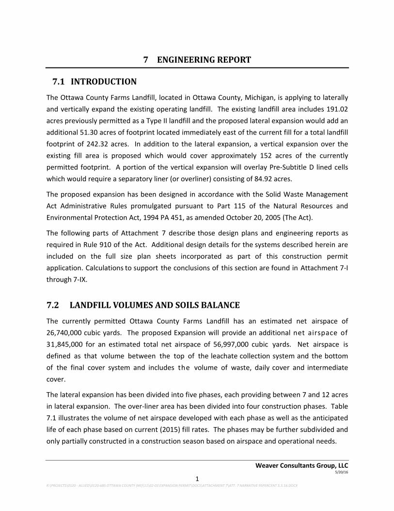
The Ottawa County Farms Landfill, located in Ottawa County, Michigan, is applying to laterally and vertically expand the existing operating landfill. The existing landfill area includes 191.02 acres previously permitted as a Type II landfill and the proposed lateral expansion would add an additional 51.30 acres of footprint located immediately east of the current fill for a total landfill footprint of 242.32 acres. In addition to the lateral expansion, a vertical expansion over the existing fill area is proposed which would cover approximately 152 acres of the currently permitted footprint. A portion of the vertical expansion will overlay Pre-Subtitle D lined cells which would require a separatory liner (or overliner) consisting of 84.92 acres.
The proposed expansion has been designed in accordance with the Solid Waste Management Act Administrative Rules promulgated pursuant to Part 115 of the Natural Resources and Environmental Protection Act, 1994 PA 451, as amended October 20, 2005 (The Act).
The following parts of Attachment 7 describe those design plans and engineering reports as required in Rule 910 of the Act. Additional design details for the systems described herein are included on the full size plan sheets incorporated as part of this construction permit application. Calculations to support the conclusions of this section are found in Attachment 7-I through 7-IX.
7.2 LANDFILL VOLUMES AND SOILS BALANCE
The currently permitted Ottawa County Farms Landfill has an estimated net airspace of 26,740,000 cubic yards. The proposed Expansion will provide an additional net airspace of 31,845,000 for an estimated total net airspace of 56,997,000 cubic yards. Net airspace is defined as that volume between the top of the leachate collection system and the bottom of the final cover system and includes the volume of waste, daily cover and intermediate cover.
The lateral expansion has been divided into five phases, each providing between 7 and 12 acres in lateral expansion. The over-liner area has been divided into four construction phases. Table 7.1 illustrates the volume of net airspace developed with each phase as well as the anticipated life of each phase based on current (2015) fill rates. The phases may be further subdivided and only partially constructed in a construction season based on airspace and operational needs.

Weaver Consultants Group, LLC 5/20/16
2 R:\PROJECTS\0120 ‐ ALLIED\0120‐685 OTTAWA COUNTY (MI)\11\02‐03 EXPANSION PERMIT\DOCS\ATTACHMENT 7\ATT. 7 NARRATIVE 95PERCENT 5.5.16.DOCX
TABLE 7.1
REMAININGPHASECONSTRUCTION,AIRSPACE,AND LIFE
Construction Phase Lined Area (acres)1
Airspace Developed2 (cubic yards)
Currently Constructed 171.57 22,900,000
Phase 7B 4.42 894,000
Phase 9 11.09 879,000
Phase 10 7.13 729,000
Phase 14 7.30 2,106,000
Phase 11 11.73 994,000
Phase 12 10.25 3,241,000
Phase 13 11.07 5,372,000
Phase 154 37.75 11,099,000
Phase 16A 17.90 1,303,000
Phase 8A 7.29 603,000
Phase 16B 11.91 1,074,000
Phase 8B 7.74 5,803,000
Total 317.15 56,997,000
Notes: 1. Lined area includes Pre‐Subtitle D Cells A‐E and Subtitle D Phases 1‐7A.
2. Currently constructed airspace is as of 2016 aerial topography compared to proposed grades. Subsequent volumes are incremental airspace with 3:1 interior slopes and 4:1 design grades on exterior slopes.
3. Estimated Life is based on a filling rate of 600,000 cy per year. 4. Phases showing estimated life beyond 2 years may be constructed in smaller sections with a temporary separation berm.
Approximately 4,714,000 cubic yards of soil will be required for subgrade fill, embankment construction, daily cover, intermediate cover and final cover as shown on Table 7.2. The bottom liner system will be comprised of either compacted soil liner and geosynthetic materials, or all geosynthetic materials, eliminating the need for compacted soil liner material. Sands and gravels for the leachate collection system will be purchased from off‐site sources.

Weaver Consultants Group, LLC 5/20/16
3 R:\PROJECTS\0120 - ALLIED\0120-685 OTTAWA COUNTY (MI)\11\02-03 EXPANSION PERMIT\DOCS\ATTACHMENT 7\ATT. 7 NARRATIVE 95PERCENT 5.5.16.DOCX
TABLE 7.2
EARTHWORK QUANTITIES
Soil Requirements Cubic Yards
Subgrade/Embankment 525,000
Over-liner 631,000
Terraces 350,000
Daily/Intermediate Cover 1,813,000
Final Cover 1,371,000
Total 4,690,000
Approximately 3,940,000 cubic yards of on-site soil borrow will be available from the cell excavation and the pond excavation as shown on Table 7.3. The shortfall in soil is expected to come from an existing borrow source located on south side of Garfield Street.
TABLE 7.3
AVAILABLE SOIL QUANTITIES
On-Site Soil Available Cubic Yards
Excavation Quantity (Phases 8 through 13) 3,790,000
Basin and Ditches 150,000
Total 3,940,000
Weaver Consultants Group, LLC 5/20/16
4 R:\PROJECTS\0120 - ALLIED\0120-685 OTTAWA COUNTY (MI)\11\02-03 EXPANSION PERMIT\DOCS\ATTACHMENT 7\ATT. 7 NARRATIVE 95PERCENT 5.5.16.DOCX
Volumes were estimated using the land development support software to AutoCAD 2016. Each surface was modeled 3-dimensionally and compared to determine cut and fill between surfaces.
7.3 CHARACTERISTICS OF UNDERLYING SOILS
7.3.1 Description
Extensive investigations were conducted as part of this permit application and the previous expansion to define the subsurface conditions at the Ottawa County Farms Landfill. Most recently, the subsurface investigation conducted for the lateral expansion to the east was completed by Engineering & Environmental Solutions (EES) in 2015.
The glacial sediments beneath the site are divided into four stratigraphic units based on their hydrogeologic characteristics. The four units, from top to bottom, include (1) an upper continuous clay unit approximately 60 to 170 feet thick, (2) an upper discontinuous sand unit which ranges from 5 to 75 feet thick, (3) a lower discontinuous clay unit which has a maximum thickness of approximately 45 feet, and (4) a lower discontinuous sand unit which has a maximum thickness of approximately 35 feet. The depth to bedrock beneath the site was found to range from approximately 165 to 205 feet below ground surface.
Upper Clay Unit: The upper clay unit consists of massive clay beds (CL) interstratified with poorly graded sand lenses (SP). Clays are more susceptible to consolidation and may have weaker strength properties; therefore, laboratory analyses of undisturbed samples of this layer were performed. The laboratory results are included in Attachment 7-I.
Upper Sand Unit: The upper sand unit consists of poorly-graded, fine- to medium-grained and sandy silt (SP-SC) with an average thickness of 35 feet. This water-bearing sand unit thins to the west and is characteristic of glacial outwash deposits.
Lower Clay Unit: The lower clay unit was found to be discontinuous with a maximum thickness of approximately 45 feet and consists primarily of sandy clay (SC) with minor silt (ML) and sandy silt lenses.
Lower Sand Unit: The lower sand unit consists of poorly graded, medium- to coarse-grained sand with a layer of gravel found at the base of the unit. This unit was found to be discontinuous and ranges from 20-35 feet thick beneath the eastern portion of the site.
Bedrock: The bedrock consists of sandstone and limestone of the Marshall Formation and shale and gypsum of the Michigan Formation and is relatively flat beneath the site except beneath the northeastern portion. In this vicinity, the bedrock surface rises and the top of the upper

Weaver Consultants Group, LLC 5/20/16
5 R:\PROJECTS\0120 - ALLIED\0120-685 OTTAWA COUNTY (MI)\11\02-03 EXPANSION PERMIT\DOCS\ATTACHMENT 7\ATT. 7 NARRATIVE 95PERCENT 5.5.16.DOCX
sand unit is closer to the ground surface.
A more extensive description of the site geology is presented in the Hydrogeological Investigation Report prepared by EES which is contained in Volume II, Attachment 4.
7.3.2 Foundation Settlement Analysis
The design of the lateral and vertical expansion areas requires that minimum slopes be maintained on leachate collection pipes after consideration of consolidation settlement of the foundation under the weight of the overlying landfill. At the Ottawa County Farms Landfill, three criteria for minimum post-settlement leachate collection pipe slope were considered depending on location.
• Lateral Expansion Area (Phases 9 through 13): Rule 423 requires that an applicant for a new disposal area demonstrate that the slope of the leachate collection pipes be a minimum of 1% after consolidation settlement.
• Existing Landfill (Phases 1 through 8): Leachate collection pipes in these disposal areas were designed and installed with a slope of approximately 1%. Rule 419 requires that an applicant for a vertical expansion demonstrate that the slope of the leachate collection pipes be a minimum of 0.5% after consolidation settlement.
• Existing Landfill (Cells A through E): Leachate collection pipes in these disposal areas were designed and installed with a slope of approximately 0.4%. Settlement analysis for this area was used to demonstrate that a positive drainage slope was maintained along the leachate collection pipe after consolidation settlement.
Foundation consolidation settlement analyses were performed on six alignments along leachate collection pipes in the existing landfill and the lateral expansion area. Alignments were chosen based on potential for maximum differential settlement that could lead to a reduction of the leachate collection pipe slope. Settlement calculations are included in Appendix 7-II and are summarized below.
Vertical profiles were developed for the alignments that depict the final configuration of the landfill, base grades, and foundation soils. Final landfill configuration used in the analyses includes the existing base grades for the existing landfill, proposed base grades for the expansion area, and proposed final cover grades for the vertical/lateral expansion. The over-liner grading fill was also incorporated in the profile for the analysis on Cell B. Subsurface soil profiles were inferred from the logs of nearby soil borings and available geological cross-sections. Foundation settlement was calculated at two or three points on each of the six alignments analyzed. Settlement was calculated for the upper silty clay layer using one-
Weaver Consultants Group, LLC 5/20/16
6 R:\PROJECTS\0120 - ALLIED\0120-685 OTTAWA COUNTY (MI)\11\02-03 EXPANSION PERMIT\DOCS\ATTACHMENT 7\ATT. 7 NARRATIVE 95PERCENT 5.5.16.DOCX
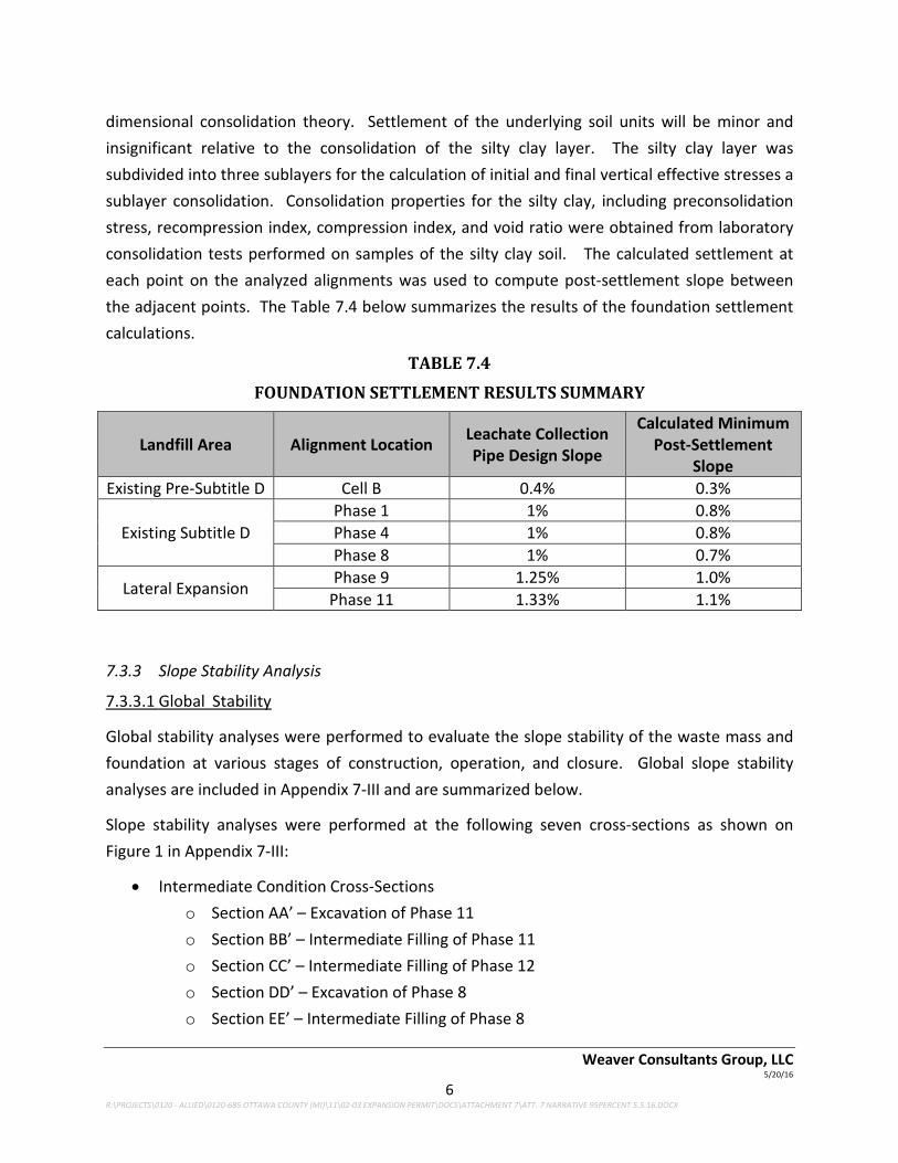
dimensional consolidation theory. Settlement of the underlying soil units will be minor and insignificant relative to the consolidation of the silty clay layer. The silty clay layer was subdivided into three sublayers for the calculation of initial and final vertical effective stresses a sublayer consolidation. Consolidation properties for the silty clay, including preconsolidation stress, recompression index, compression index, and void ratio were obtained from laboratory consolidation tests performed on samples of the silty clay soil. The calculated settlement at each point on the analyzed alignments was used to compute post-settlement slope between the adjacent points. The Table 7.4 below summarizes the results of the foundation settlement calculations.
TABLE 7.4
FOUNDATION SETTLEMENT RESULTS SUMMARY
Landfill Area Alignment Location Leachate Collection Pipe Design Slope
Calculated Minimum Post-Settlement
Slope Existing Pre-Subtitle D Cell B 0.4% 0.3%
Existing Subtitle D Phase 1 1% 0.8% Phase 4 1% 0.8% Phase 8 1% 0.7%
Lateral Expansion Phase 9 1.25% 1.0% Phase 11 1.33% 1.1%
7.3.3 Slope Stability Analysis
7.3.3.1 Global Stability
Global stability analyses were performed to evaluate the slope stability of the waste mass and foundation at various stages of construction, operation, and closure. Global slope stability analyses are included in Appendix 7-III and are summarized below.
Slope stability analyses were performed at the following seven cross-sections as shown on Figure 1 in Appendix 7-III:
• Intermediate Condition Cross-Sections o Section AA’ – Excavation of Phase 11 o Section BB’ – Intermediate Filling of Phase 11 o Section CC’ – Intermediate Filling of Phase 12 o Section DD’ – Excavation of Phase 8 o Section EE’ – Intermediate Filling of Phase 8

Weaver Consultants Group, LLC 5/20/16
7 R:\PROJECTS\0120 - ALLIED\0120-685 OTTAWA COUNTY (MI)\11\02-03 EXPANSION PERMIT\DOCS\ATTACHMENT 7\ATT. 7 NARRATIVE 95PERCENT 5.5.16.DOCX
• Final Configuration Cross-Sections o Section FF’ – Final Configuration on South Side (Phase 4 Area) o Section GG’ – Final Configuration on North Side (Cell A Area)
The geometry of the landfill liner, waste grades, and final cover were obtained from the permitted and proposed expansion design drawings. The foundation soil in the slope stability model was simplified to a single soil layer with properties consistent with the upper silty clay stratum. This is a conservative assumption because it ignores the higher strength upper and lower sand units and the hard sandy clay/dense clayey sand unit that underlie the upper silty clay layer. Top of bedrock was set at elevation 460 feet in the models. Total strength properties were used to model the silty clay foundation soil and were obtained from consolidated-undrained triaxial strength tests performed on samples taken from site borings.
The base and sidelsope liner in permitted landfill Phases 1 through 8 and the proposed expansion area Phases 9 through 13 were modeled to include a critical geosynthetic interface. In the absence of site-specific interface friction data, conservative values were assumed for interface friction of the existing landfill liner. Peak (φPeak) and residual (φRes) friction angles of φPeak =11° and φRes=8° were used to model the base liner and sideslope liner, respectively. These values were consistent with the reported use of smooth geomembrane and geosynthetic clay liner for a number of the existing disposal cells. For the proposed expansion area, allowable peak and residual friction angles were back-calculated for the intermediate filling scenario modeled in cross-section BB’ (Phase 11). Friction angles of φPeak =18° and φRes=8° were used to model the base liner and sideslope liner, respectively, in the proposed expansion area and the future Phase 8 disposal cell. These values were also used to model interface friction in the over-liner system for those cross-sections that included the over-liner. When present in a given cross-section, the final cover was modeled as a 4-foot thick soil layer (veneer stability calculations for the cover are discussed separately).
Two phreatic surfaces were included in the slope stability models. One foot of leachate head was modeled above the base and sidelsope liners and was applied to calculation of stresses in the waste, leachate layer, and the critical liner interface. A groundwater potentiometric surface model based on observed groundwater levels in 2015 was included for calculation of stresses within the foundation soils.
Intermediate configuration cross-sections were analyzed under static conditions. Final configuration cross-sections were analyzed for static and seismic conditions. The seismic loading analysis consisted of a pseudo-static stability analysis with a horizontal ground acceleration of 0.031g. The horizontal ground acceleration corresponds to the peak ground
Weaver Consultants Group, LLC 5/20/16
8 R:\PROJECTS\0120 - ALLIED\0120-685 OTTAWA COUNTY (MI)\11\02-03 EXPANSION PERMIT\DOCS\ATTACHMENT 7\ATT. 7 NARRATIVE 95PERCENT 5.5.16.DOCX
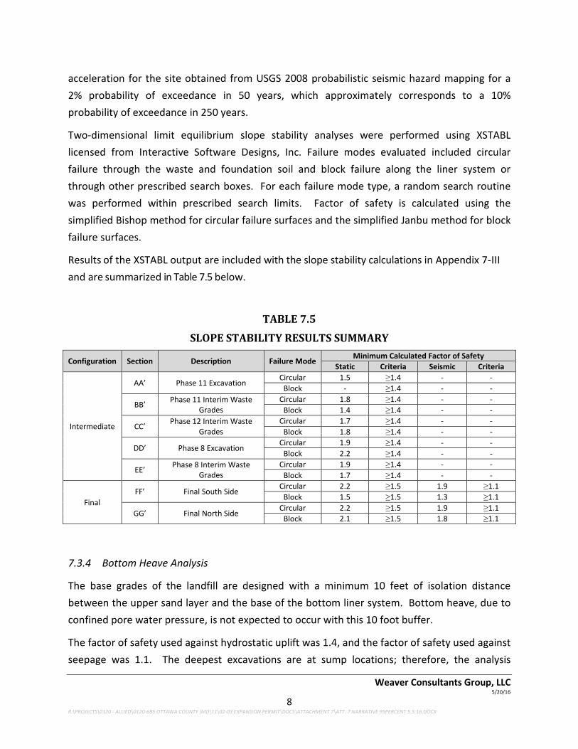
acceleration for the site obtained from USGS 2008 probabilistic seismic hazard mapping for a 2% probability of exceedance in 50 years, which approximately corresponds to a 10% probability of exceedance in 250 years.
Two-dimensional limit equilibrium slope stability analyses were performed using XSTABL licensed from Interactive Software Designs, Inc. Failure modes evaluated included circular failure through the waste and foundation soil and block failure along the liner system or through other prescribed search boxes. For each failure mode type, a random search routine was performed within prescribed search limits. Factor of safety is calculated using the simplified Bishop method for circular failure surfaces and the simplified Janbu method for block failure surfaces.
Results of the XSTABL output are included with the slope stability calculations in Appendix 7-III and are summarized in Table 7.5 below.
TABLE 7.5
SLOPE STABILITY RESULTS SUMMARY
Configuration Section Description Failure Mode Minimum Calculated Factor of Safety Static Criteria Seismic Criteria
Intermediate
AA’ Phase 11 Excavation Circular 1.5 ≥1.4 - -
Block - ≥1.4 - -
BB’ Phase 11 Interim Waste Grades
Circular 1.8 ≥1.4 - - Block 1.4 ≥1.4 - -
CC’ Phase 12 Interim Waste Grades
Circular 1.7 ≥1.4 - - Block 1.8 ≥1.4 - -
DD’ Phase 8 Excavation Circular 1.9 ≥1.4 - -
Block 2.2 ≥1.4 - -
EE’ Phase 8 Interim Waste Grades
Circular 1.9 ≥1.4 - - Block 1.7 ≥1.4 - -
Final FF’ Final South Side
Circular 2.2 ≥1.5 1.9 ≥1.1 Block 1.5 ≥1.5 1.3 ≥1.1
GG’ Final North Side Circular 2.2 ≥1.5 1.9 ≥1.1
Block 2.1 ≥1.5 1.8 ≥1.1
7.3.4 Bottom Heave Analysis
The base grades of the landfill are designed with a minimum 10 feet of isolation distance between the upper sand layer and the base of the bottom liner system. Bottom heave, due to confined pore water pressure, is not expected to occur with this 10 foot buffer.
The factor of safety used against hydrostatic uplift was 1.4, and the factor of safety used against seepage was 1.1. The deepest excavations are at sump locations; therefore, the analysis

Weaver Consultants Group, LLC 5/20/16
9 R:\PROJECTS\0120 - ALLIED\0120-685 OTTAWA COUNTY (MI)\11\02-03 EXPANSION PERMIT\DOCS\ATTACHMENT 7\ATT. 7 NARRATIVE 95PERCENT 5.5.16.DOCX
resulted in the sump elevations ranging from 592 to 610. The sump elevations are set based on variations in groundwater levels and variations in sand layer elevations. Seasonal groundwater level changes were addressed in the calculation by analyzing historical ground water elevations and adding four feet to the current estimated levels to account for the average standard deviation of the historic data. Calculations for this analysis are included in Attachment 7-VIII and illustrated on Figure 1 of the Attachment.
7.4 LINER SYSTEM DESIGN
7.4.1 Description
The lateral expansion area is considered a monitorable unit and will take advantage of the low permeability soil beneath the site which forms a natural soil barrier in compliance with Rule 422(2)(a). A single composite liner and leachate collection system will be constructed as required by Rule 421(1). Documentation that the continuity and permeability of the natural soil meets the requirements of Part 115 is included in the Hydrogeological Investigation Report prepared by EES contained in Volume II, Attachment 4.
The base of liner system grades provide at least 10 feet of isolation to groundwater at all locations, including at sumps as illustrated on Figure 9 contained in Volume II, Attachment 4 of this application package. The base liner system grades also provide adequate Factor of Safety against bottom heave as described in Section 7.3.4.
Lateral Expansion
It is proposed that the composite liner system for the lateral expansion be comprised of a 24” thick recompacted soil liner or geosynthetic clay liner (GCL) overlain by a 60-mil textured high density polyethylene (HDPE) geomembrane.
Attachment 7-IV includes calculations that demonstrate that the stresses imposed on the various components of the liner system are within acceptable limits. This includes stresses due to placement, construction of overlying components and waste placement.
Vertical Expansion
A portion of the vertical expansion will overlay existing waste landfilled in cells that do not meet Subtitle D liner requirements. Therefore, a liner system and leachate collection system will be constructed that separates the underlying existing waste from waste placed as part of the vertical expansion. This separatory liner system or “overliner” is proposed to be comprised of a soil or clean fill grading layer, overlain by GCL and a 60-mil linear low density polyethylene

Weaver Consultants Group, LLC 5/20/16
10 R:\PROJECTS\0120 - ALLIED\0120-685 OTTAWA COUNTY (MI)\11\02-03 EXPANSION PERMIT\DOCS\ATTACHMENT 7\ATT. 7 NARRATIVE 95PERCENT 5.5.16.DOCX
(LLDPE) geomembrane. The liner system will be overlain by a leachate collection sand layer with interbedded leachate collection pipes.
CTI and Associates, Inc. (CTI) prepared a settlement and liner strain analysis for the overliner portion of the proposed expansion. Their approach utilized a probabilistic model to simulate differential settlement and the effect on the proposed overliner system performance resulting in a proposed minimum liner design slope of 5% in the north-south direction and 3% in the east-west direction. The completed overliner settlement analysis prepared by CTI is provided in Attachment 12.
7.4.2 Characteristics of Soils for Liner Construction
Ottawa County Farms Landfill is proposing to utilize either a minimum 24-inch thick recompacted soil liner or geosynthetic clay liner (GCL) for the clay components of the composite liner system. If used for the lower portion of the composite liner system, the compacted soil liner will be constructed from natural soils excavated during preparation of the subgrade at the side and be in compliance with Rule 913 of Part 115, P.A. 451. The Hydrogeological Investigation Report presents boring logs and test data documenting that the site soils extending from the surface to depths well below the proposed sub-base liner grades are suitable for compacted soil liner construction.
The recompacted soil liner will have a hydraulic conductivity of not more than 1.0 x 10⁻⁷ cm/sec and be installed in accordance with the Construction Quality Assurance (CQA) Plan included as Attachment 9 of this application package.
7.4.3 Characteristics of Geosynthetic Clay Liner Material
In lieu of a 24-inch recompacted soil liner, the soil component of the liner system may consist of a GCL, in compliance with Rule 914 of Part 115, P.A. 451.
The GCL will consist of a layer of sodium bentonite sandwiched between two layers of geotextile. At least one of the layers of geotextile will be a needle-punched, non-woven geotextile. The finished GCL will be needle- punched, or otherwise modified, to increase the internal shear strength of the finished product.
The GCL will meet the specifications provided in the CQA Plan which is included as Attachment 9 of this application package. The CQA Plan also includes the methods of handling and installation to be followed.
GCLs currently on the market and meeting the specifications provided in the CQA are widely accepted in the solid waste industry and have been demonstrated to be resistant to

Weaver Consultants Group, LLC 5/20/16
11 R:\PROJECTS\0120 - ALLIED\0120-685 OTTAWA COUNTY (MI)\11\02-03 EXPANSION PERMIT\DOCS\ATTACHMENT 7\ATT. 7 NARRATIVE 95PERCENT 5.5.16.DOCX
degradation due to prolonged leachate contact and biological attack. The GCLs are delivered within a wrapper and geomembrane is placed over the GCL shortly after installation. Therefore exposure to ultraviolet radiation is minimal.
Rule 914 of The Act allows the use of a bentonite geocomposite liner or geosynthetic clay liner (GCL) in place of a compacted soil liner if the combination of its thickness and hydraulic conductivity results in liquid migration through the liner is less than the rate of migration through 2 feet of clay having a saturated permeability of 1x10⁻⁷ cm/sec. Furthermore, Rule 914 requires that the bentonite be contained on each side by fabric, geotextile or geomembrane and that the GCL shall be installed in accordance with the manufacturer's specifications.
Flow through a permeable material is calculated using the following equation:
Q = k*i*A (7.4-1)
where: Q = flow in cm3/sec
k = permeability in cm/sec
I = hydraulic gradient (unitless) = ∆h/L
L = thickness of liner
∆h = thickness of liner plus maximum head above liner (1’)
A = area in cm2
For 2 feet of clay liner with a foot of head over the liner, equation 7.4-1 is as follows:
Q = (1x10⁻⁷ cm/sec)*(3 ft/2 ft)*(1 cm2) = 1.5x10⁻⁷ cm3/cm2 (7.4-2)
Flow through GCL materials are currently defined in terms of “flux” which is measured per ASTM D5887 and is defined as the following:
Flux = k*i (7.4-3)
substituting equation 7.4-3 into 7.4-1
Q = Flux*A (7.4-4)
and therefore the flux must be:
Flux < 1.5x10⁻⁷ cm/sec
GCLs included in the Specifier's Guide 2015 provided by the Geotechnical Fabrics Report provide manufacturing results of flux less than or equal to 1x10⁻⁸ cm/s. Therefore, GCLs will be adequate, provided they have a flux less than 1.5x10⁻⁷ cm/sec.

Weaver Consultants Group, LLC 5/20/16
12 R:\PROJECTS\0120 - ALLIED\0120-685 OTTAWA COUNTY (MI)\11\02-03 EXPANSION PERMIT\DOCS\ATTACHMENT 7\ATT. 7 NARRATIVE 95PERCENT 5.5.16.DOCX
7.4.4 Polyethylene Geomembrane
A polyethylene geomembrane, in compliance with Rule 915 of Rule 115 P.A. 451, will be installed as the upper component of the composite liner system. For the lateral expansion, the geomembrane shall be high-density polyethylene. In the overliner area, the geomembrane shall be low-density polyethylene due to its enhanced ability to withstand strain due to differential settlement.
The geomembrane specifications, testing rates and procedures are provided in the CQA Plan included as Attachment 9 of this application package. The CQA Plan also includes the methods of storage, handling, installation, and testing to be followed.
HDPE and LLDPE geomembranes that are currently on the market and meeting the specifications provided in the CQA Plan are widely accepted in the solid waste industry and have been demonstrated to be resistant to degradation due to prolonged ultraviolet radiation, leachate contact and biological attack.
7.5 LEACHATE COLLECTION SYSTEM
7.5.1 Introduction
The leachate collection system is designed in accordance with Rule 423 of Part 115, PA 451, to limit the leachate head on the liner to less than one foot, except at the sumps.
Lateral Expansion
Within the lateral expansion area, the base grades of the liner system are designed to slope at a 2% grade toward the leachate collection pipes and at a 1% grade (post-settlement) along the pipes to the sump for each cell. The grades along leachate collection pipes have been increased over the regulatory requirement of 1% in order to account for differential settlement due to waste overburden as presented in Section 7.3.3 and corresponding calculations presented in Attachment 7-II.
Vertical Expansion
Within the overliner area, the proposed base grades of the liner system were evaluated by CTI to provide the same degree of confidence in post-settlement drainage as the cell floors in the lateral expansion. The completed overliner settlement analysis prepared by CTI is provided in Volume IV of this application package. For the overliner, the grades along the leachate collection system will be 5% in the north-south direction and 3% in the east-west direction. Leachate collection pipes will be placed with the collection system to enhance leachate

Weaver Consultants Group, LLC 5/20/16
13 R:\PROJECTS\0120 - ALLIED\0120-685 OTTAWA COUNTY (MI)\11\02-03 EXPANSION PERMIT\DOCS\ATTACHMENT 7\ATT. 7 NARRATIVE 95PERCENT 5.5.16.DOCX
collection.
7.5.2 Leachate Generation Calculations
The Hydrologic Evaluation of Landfill Performance (HELP) model was used to estimate the leachate generation and maximum leachate head on the liner under several conditions; open cell, one lift of waste placement, after full waste placement, and closed conditions. The HELP model scenarios and results are presented in Attachment 7-V indicating that the maximum head on the liner does not exceed 12 inches except at the sumps.
7.5.3 Leachate Collection Drainage Layer
The drainage layer of the leachate collection system shall be comprised of 12 inches of natural sand having a minimum permeability of 1x10⁻² cm/sec. The sand shall have less than 5% fines (percent passing #200 sieve) and shall have minimal carbonate content. Material specifications, testing criteria, placement documentation, and certification procedures are provided in the CQA Plan which is included as Attachment 9 of this application package
An additional 12 inches of protective soil layer having a permeability no less than 1x10⁻⁴ cm/sec may be placed directly over the sand layer or, in lieu of that, a 5 foot layer of select waste fill will be placed as a protection layer. A geosynthetic drainage layer, such as a double-sided geocomposite, may be selected as an alternate to the 12 inch sand drainage layer provided it meets the equivalent minimum permeability of 1 cm/sec and is used in conjunction with a minimum 12 inch layer of 1x10⁻³ cm/sec soil drainage media. Calculations are included in Attachment 7-V demonstrating the capacity and permeability of either layer will be sufficient.
7.5.4 Leachate Collection Pipe
Lateral Expansion and Phase 8 Redesign
For the lateral expansion and Phase 8 redesign, a system of perforated HDPE pipe will be embedded within the drainage layer of the leachate collection system to convey leachate to the removal sumps. In Phases 9 and 10 the pipes flow to the north and in Phases 11, 12, and 13 the pipes flow to the south. Phase 8 will drain towards the west. The leachate collection pipes will drain to perforated header pipes located at the inside toe of the outer containment berms which will direct flow to the sumps. Except for the header pipes, the LCS pipes are at 100-foot spacing with the maximum floor flow length to the pipes of 50 feet.
Phase 1 and Phase 2 Sumps
The sumps for existing Phases 1 and 2 are located on the east side of the previously permitted limits of waste. Therefore, the lateral and vertical expansion will require modification to these
Weaver Consultants Group, LLC 5/20/16
14 R:\PROJECTS\0120 - ALLIED\0120-685 OTTAWA COUNTY (MI)\11\02-03 EXPANSION PERMIT\DOCS\ATTACHMENT 7\ATT. 7 NARRATIVE 95PERCENT 5.5.16.DOCX
leachate removal points. Two options were reviewed, extension of the existing sideslope sump riser pipes or draining of Phases 1 and 2 by gravity into lateral expansion Phase 9.
Option 1 - Extending Sideslope Riser Pipes. This option would require extending the existing sideslope riser pipes in order that pumps could still be lowered into the sumps for leachate removal. Generally the sideslope riser pipes would need to be extended vertically as waste is placed. Vertical extensions would be about 80 feet for Phase 1 and 180 feet for Phase 2.
The following benefits of this option were identified:
• Leachate from Phases 1 and 2 would continue to be pumped separately. • No odors related to waste excavation. • No excavation of outer soil berm to access sumps.
The following issues were identified:
• The existing sideslope risers are in questionable condition and work would need to be done to reinforce them.
• Downdrag due to waste settlement on vertical manholes is considerable. Extra controls such as sheathing of the manholes would be needed to limit impact of downdrag.
• Incremental extensions of the vertical manhole would need to be installed as waste is placed.
• The vertical manholes will be subject to lateral displacement due to waste settlement and vehicle strikes/loads. Once knocked out of vertical alignment it may not be possible to pull or to get pumps to the base of the sump.
• If access to the sump is not possible due to vertical extension tilting or collapsing, there are not good solutions for re-establishing pumping from the sump.
Option 2 - Draining to Lateral Expansion Phase 9. This option would require the eastern berm of Phases 1 and 2 to be partially removed (notched) so that the sumps could be drained by gravity into the lateral expansion. In order to remove the berm, waste would need to be excavated to expose the notches and sumps. The slopes of the notches would need to be lined.
The following benefits for this option were identified:
• No vertical structures would need to be extended through waste, resulting in the potential issues identified above.

Weaver Consultants Group, LLC 5/20/16
15 R:\PROJECTS\0120 - ALLIED\0120-685 OTTAWA COUNTY (MI)\11\02-03 EXPANSION PERMIT\DOCS\ATTACHMENT 7\ATT. 7 NARRATIVE 95PERCENT 5.5.16.DOCX
• Once installed, there is little risk that Phases 1 and 2 will not drain effectively, maintaining less than 12 inches of head throughout.
The following issues were identified:
• The excavation of waste will create odors. • To excavate waste and the berm, infrastructure such as gas wells, laterals and
headers will need to be removed/rerouted. • Tie-in of the liner systems from Phases 1 and 2 to Phase 9 will be hampered by
leachate generation and surface water run-on. • Constructing in the sump area will be a hazardous work environment due to
landfill gas. Monitoring and forced ventilation will be required to maintain a safe breathing and non-explosive condition.
• A number of the existing cleanouts for Phases 1 and 2 will no longer be accessible.
Despite the many issues identified with the excavation of notches, this option was chosen on the basis that long-term ability to remove leachate from Phases 1 and 2 will be maintained. A detailed construction work plan for building the notches is provided in Attachment 11.
Vertical Expansion Separatory Liner
For the northern majority of the vertical expansion overliner, a system of perforated HDPE pipe will be placed within the drainage layer of the leachate collection system to convey leachate to the removal sumps located along the north portion of the overliner. Leachate will flow from the highpoint of the overliner grades northward to the corresponding sump for Phases 14, 15, and 16. A header pipe will be located along the toe of the north containment berm which will drain either east or west toward their respective sump.
From the highpoint of the overliner grades to the south, a system of five foot wide geocomposite strip drains with drainage media will be placed within the drainage layer of the leachate collection system. Liquid from the south portion of the overliner will be collected in a gravel trench and directed to the leachate conveyance system through a perforated pipe as described below. For Phase 15, this trench transitions to a solid 6-inch diameter HPDE pipe with clay backfill 200 feet from the solid waste boundary and connects to the existing gravity line located along the south side of the landfill. For Phase 16, this trench drains to the Phase 8 sump to be managed with other collected leachate.
The leachate collection pipe is 6-inch diameter high density polyethylene with a minimum wall thickness defined by an SDR (standard design ratio) of 11. SDR is defined as the nominal

Weaver Consultants Group, LLC 5/20/16
16 R:\PROJECTS\0120 - ALLIED\0120-685 OTTAWA COUNTY (MI)\11\02-03 EXPANSION PERMIT\DOCS\ATTACHMENT 7\ATT. 7 NARRATIVE 95PERCENT 5.5.16.DOCX
diameter of the pipe divided by the thickness of the pipe wall. The SDR of the pipe has been selected to withstand the stresses applied during the life of the landfill as demonstrated in Attachment 7-VI. The diameter of the pipe has been selected to facilitate inspection and cleaning, if needed. The flow capacity of the 6-inch pipe exceeds that required to transfer leachate, as demonstrated in Attachment 7-VII. The flow capacity of a 6 inch HDPE pipe at 1% slope is about 1,390 gpm. The maximum flow expected under open conditions to any LCS pipe based on HELP modeling is about 8.63 gpm.
Perforated pipes will have ½ inch diameter holes space every 6 inches as shown on the engineering plan details. The pipes will be encased in gravel to enhance flow characteristics and prevent clogging of the pipe by the finer drainage sand.
The leachate collection pipes installed in Phases 1 through 8 are 6-inch diameter SDR 11 which are adequate to withstand additional stresses created by the expansion. The leachate collection pipes installed in Cells A through E are Schedule-80 PVC which is adequate to withstand additional overburden stress. The PVC and HDPE pipe deflection calculations are presented in Attachment 7-VI.
The gravel wrap shall have a minimum permeability of 1x10⁻¹ cm/sec, have less than 5% percent fines and shall contain minimal carbonate content. The geotextile used in the pipe wrap shall have a minimum weight of 6 ounces per square yard. A 6 ounce per square yard non-woven geotextile will be placed between the pipe bedding and granular drainage layer to prevent the intrusion of fines into the gravel pipe bedding.
The materials selected for the pipe and wrap have been demonstrated through many landfill applications to be resistant to deterioration due to chemical, biological and ultraviolet radiation attack.
7.5.5 Leachate Pipe Cleanouts
Each leachate collection pipe will be accessible throughout the life of the landfill by cleanout risers except those located along the east side of Phases 1 and 2 as indicated in the Sump Connection Construction Plan provided as Attachment 11.
Cleanouts are constructed of 6" solid HDPE pipe with a minimum wall thickness of SDR-11. The cleanouts have been sized to facilitate inspection by camera or cleaning by jetting or pigging. Long radius elbows will be used to connect cleanouts to collection pipes in order to facilitate inspections/cleaning.

Weaver Consultants Group, LLC 5/20/16
17 R:\PROJECTS\0120 - ALLIED\0120-685 OTTAWA COUNTY (MI)\11\02-03 EXPANSION PERMIT\DOCS\ATTACHMENT 7\ATT. 7 NARRATIVE 95PERCENT 5.5.16.DOCX
7.5.6 Leachate Collection Sumps, Pumps and Sideslope Risers
Lateral Expansion
Sumps equipped with pumps for leachate removal are located at the low point of each of the phases. The base elevations of the sumps were established by maintaining a minimum 10 feet of separation to groundwater and maintaining an adequate factor of safety against bottom heave. The lateral expansion proposes 5 permanent sumps for collecting leachate from the landfill liner system. The sumps will collect leachate from areas ranging from 7 to 12 acres and will collect an estimated 53,200 total gallons per day (51.3 acres x 1,036 gallon/acre/day) or approximately 37 gallons per minute.
Vertical Expansion
Sumps equipped with pumps for leachate removal are located along the north side of the overliner phases (Phases 14 through 16). These sumps will collect leachate from areas ranging from 7 to 27 acres and will collect an estimated 55,660 gallons per day (53.7 acres x 1,036 gallon/acre/day) or approximately 39 gallons per minute.
Sumps will be constructed the same for both the lateral and vertical expansion areas. Each will have a minimum base dimension of 12 feet by 12 feet by a minimum of 3 feet deep. The sumps will be backfilled with coarse aggregate meeting the specifications of the pipe wrap stone (Section 7.5.4). The sump will also be wrapped in 6 oz/sy geotextile prevent excessive intrusion of fines. The sump will be accessed by two 18-inch SDR 11 HDPE sideslope riser pipes. One pipe will be the primary leachate removal riser while the second pipe will provide redundancy should alternate or additional removal capacity be needed. The sideslope riser pipes within the sump will have ½ inch perforations at 6-inch spacing to allow leachate to readily flow to the pump. The sideslope riser pipes will extend up the 3:1 interior slopes to the outside edge of the limits of waste placement.
In order to maintain consistency between different cells at the site, an EPG model WSD-15-3 (2 HP) or similar is specified for the lateral expansion phases. This pump was modeled with the anticipated static and dynamic heads as well as with the modeled leachate generation in Attachment VII.
Immediately after construction, additional pumps may be needed to dewater the cell after storm events. This stormwater, provided it is not leachate, can be discharged to the perimeter drainage ditches.
The pumps will be controlled with a solenoid switch that activates the pump when the leachate

Weaver Consultants Group, LLC 5/20/16
18 R:\PROJECTS\0120 - ALLIED\0120-685 OTTAWA COUNTY (MI)\11\02-03 EXPANSION PERMIT\DOCS\ATTACHMENT 7\ATT. 7 NARRATIVE 95PERCENT 5.5.16.DOCX
reaches a depth of 30 inches within the sump. The pumps will deactivates when the sump has been drained to 12 inches, and activates a high level alarm if the leachate reaches a depth of 42 inches in the sump. The pumps will also be controlled by float switches in the leachate storage tank which will prevent the pumps from activating when the tank is full.
Leachate system sizing calculations are included in Attachment 7-VII. HDPE pipe deflection calculations for sideslope risers are presented in Attachment 7-VI. HDPE has a high strain capacity; therefore, stress is the limiting factor, as included in Attachment 7-VI(3).
7.5.7 Leachate Conveyance System
The leachate pumps discharge through a 2-inch diameter pipe to the leachate force main or gravity sewer. On the south side of the landfill, existing Phases 3 through 7 and future Phase 8 discharge to the existing 6” gravity sewer that also provides conveyance for existing Cells C through E. This gravity sewer conveys leachate to existing Lift Station 1 (or the South Lift Station). Phases 11 through 13 in the lateral expansion will discharge to a new 6" gravity sewer which will also drain to Lift Station 1. Liquid collected in Lift Station 1 is pumped through a dual contained forcemain around the landfill perimeter to the leachate tank.
A new lift station, Lift Station 2 (or the North Lift Station) will be constructed near the northeast corner of the existing landfill. Leachate from existing Cells A-Extension and B-Extension will pump directly to Lift Station 2. A new 6” gravity sewer will be constructed along the north boundary of the lateral expansion to drain leachate from Phases 9 and 10 into Lift Station 2. From Lift Station 2 liquids will be pumped via the existing dual contained forcemain to the leachate tank.
7.5.8 Leachate Storage Tanks and Disposal
Leachate collected from the Ottawa County Farms Landfill is temporarily stored in one 300,000 gallon aboveground storage tank. The leachate storage facility, located on the north side of the landfill, includes secondary containment and load-out pad. Currently the majority of leachate is transferred into tanker trucks and transported to a local waste water treatment plant for final disposal. Leachate recirculation is allowed at the facility although only a minor percentage of liquid is typically recirculated. Direct sewer discharge may be considered as a long term disposal option should it become available in the future.
Calculations in Attachment 7-VII demonstrate that 545,820 gallons of storage is needed to contain leachate generated over a five day period. Therefore, an additional 300,000 gallon tank is specified for this expansion application. If direct sewer discharge becomes available before the second tank becomes necessary, the second tank will not be built.
Weaver Consultants Group, LLC 5/20/16
19 R:\PROJECTS\0120 - ALLIED\0120-685 OTTAWA COUNTY (MI)\11\02-03 EXPANSION PERMIT\DOCS\ATTACHMENT 7\ATT. 7 NARRATIVE 95PERCENT 5.5.16.DOCX
7.6 MISCELLANEOUS DESIGN
7.6.1 Surface Water Run-on Controls
The expansion area is contained within a berm located higher than the surrounding topography; therefore, surface water run-on to waste areas has been largely eliminated and no permanent perimeter run-on controls are provided.
The area of waste disposal will be vulnerable to run-on from the surface of waste placed at higher elevations. Where possible, berms or ditches will be constructed to divert flow from these areas to perimeter surface water controls. Surface water that comes in contact with waste, leachate, or waste under daily cover will be treated as leachate. Surface water from final cover, intermediate cover, and areas without waste will be treated as surface water and be routed to the existing and proposed sedimentation basins.
7.6.2 Surface Water Run-off Controls
A system of drainage channels, downlets, and ditches has been designed to route the surface water flow to the existing and future sedimentation basins. The ditches have been designed to manage flow from the 24-hour, 25-year storm. The design calculations are presented in Attachment 7-IX.
The stormwater run-off will be routed to the existing and future north sedimentation ponds. The existing and future ponds have been evaluated with the flow from the existing and expansion areas to demonstrate that the pond sizes and discharge structures will adequately handle anticipated flows. Supporting calculations are provided in Appendix 7-IX.
The Universal Soil Loss Equation was used to determine the amount of sediment that would be transported through the ditches to the ponds. It was determined that the site should inspect the ponds on an annual basis to determine if excessive silt buildup has occurred. The ponds should be cleaned once the sediment has accumulated to the first perforation of the outlet structure.
7.6.3 Wind Dispersal of Particulate Matter
The Ottawa County Farms Landfill accepts a small percentage of the total waste stream that is subject to particulate dispersion; therefore, minimizing fugitive dust emissions will be performed by operational means rather than structural controls.

Weaver Consultants Group, LLC 5/20/16
20 R:\PROJECTS\0120 - ALLIED\0120-685 OTTAWA COUNTY (MI)\11\02-03 EXPANSION PERMIT\DOCS\ATTACHMENT 7\ATT. 7 NARRATIVE 95PERCENT 5.5.16.DOCX
7.6.4 Gas Generation
Decomposing waste within the landfill will produce a gas that is approximately 50% methane (CH4) and 50% Carbon Dioxide (CO2), Oxygen (O2), and balance gases. The amount and rate of landfill gas generated has been modeled based on an approximation of the mass of waste in place and current waste receipt rate. This analysis was used to develop the layout of the gas control system. The gas collection system is designed to collect the gas generated within the landfill through a network of collection wells and piping within the limits of waste. Collected gas is routed via HDPE headers to an enclosed flare located at the northeast corner of the landfill. The Gas Collection and Control System (GCCS) Design Plan is provided in Volume IV of this construction permit application package.
7.7 CERTIFICATION
The engineering plan sheets, reports, calculations, and written plans were prepared under the direction of Tamara A. Perkins, a registered professional engineer in the State of Michigan. The plan sheets and engineering reports have been sealed in accordance with Rule 910(9).