atsc standard: interactive services standard · 2020-03-10 · 8.4.1 delivery of pdi tables in...
TRANSCRIPT
ATSC A/105:2015 Interactive Services Standard 29 October 2015
ATSC Standard: Interactive Services Standard
A/105 29 October 2015
Advanced Television Systems Committee 1776 K Street, N.W. Washington, D.C. 20006 202-872-9160
ATSC A/105:2015 Interactive Services Standard 29 October 2015
The Advanced Television Systems Committee, Inc. is an international, non-profit organization developing voluntary standards for digital television. The ATSC member organizations represent the broadcast, broadcast equipment, motion picture, consumer electronics, computer, cable, satellite, and semiconductor industries.
Specifically, ATSC is working to coordinate television standards among different communications media focusing on digital television, interactive systems, and broadband multimedia communications. ATSC is also developing digital television implementation strategies and presenting educational seminars on the ATSC standards.
ATSC was formed in 1982 by the member organizations of the Joint Committee on InterSociety Coordination (JCIC): the Electronic Industries Association (EIA), the Institute of Electrical and Electronic Engineers (IEEE), the National Association of Broadcasters (NAB), the National Cable Telecommunications Association (NCTA), and the Society of Motion Picture and Television Engineers (SMPTE). Currently, there are approximately 150 members representing the broadcast, broadcast equipment, motion picture, consumer electronics, computer, cable, satellite, and semiconductor industries.
ATSC Digital TV Standards include digital high definition television (HDTV), standard definition television (SDTV), data broadcasting, multichannel surround-sound audio, and satellite direct-to-home broadcasting.
Note: The user's attention is called to the possibility that compliance with this standard may require use of an invention covered by patent rights. By publication of this standard, no position is taken with respect to the validity of this claim or of any patent rights in connection therewith. One or more patent holders have, however, filed a statement regarding the terms on which such patent holder(s) may be willing to grant a license under these rights to individuals or entities desiring to obtain such a license. Details may be obtained from the ATSC Secretary and the patent holder.
Revision History
Version Date
Candidate Standard approved by TG1 18 October 2013
Standard approved 29 October 2015
ATSC A/105:2015 Interactive Services Standard 29 October 2015
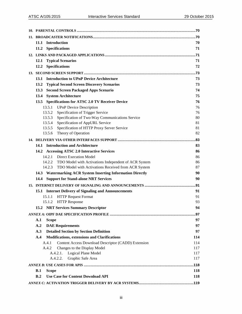
Table of Contents 1. SCOPE ......................................................................................................................................................1
1.1 Introduction 1 1.2 Organization 1
2. REFERENCES ..........................................................................................................................................2 2.1 Normative References 2 2.2 Informative References 3
3. DEFINITIONS ..........................................................................................................................................3 3.1 Compliance Notation 3 3.2 Treatment of Syntactic Elements 4
3.2.1 Reserved Elements 4 3.3 Acronyms and Abbreviation 4 3.4 Terms 6 3.5 Extensibility 6
3.5.1 Backward-compatible Extensibility Mechanisms 6 3.5.2 Non-backward-compatible Extensibility Mechanisms 7 3.5.3 Extensions with unknown compatibility 7 3.5.4 Descriptor Processing Considerations 7
3.6 XML Schema and Namespace 8 4. INTERACTIVE SERVICES MODEL .......................................................................................................9
4.1 Triggered Interactive Adjunct Data Services 9 4.2 Interactivity in Stand-Alone NRT Services 10 4.3 Unbound Interactive Applications 10
5. APPLICATION MODEL ........................................................................................................................ 11 5.1 TDO Lifecycle 11
5.1.1 TDO Lifecycle Overview 11 5.1.2 TDO Signaling 12 5.1.3 TDO States 12 5.1.4 TDO State Changing Events 12 5.1.5 TDO State Transition Rules 13 5.1.6 User Control of TDOs 14
5.2 NDO Lifecycle 15 5.2.1 NDO Lifecycle Overview 15 5.2.2 NDO States 15 5.2.3 NDO State Changing Events 15 5.2.4 NDO State Transition Rules 16
5.3 UDO Lifecycle 17 5.3.1 UDO Lifecycle Overview 17 5.3.2 UDO States 18 5.3.3 UDO State Changing Events 18 5.3.4 UDO State Transition Rules 18
5.4 Application Boundary 19 6. SIGNALING OF TDO PROPERTIES AND EVENTS ............................................................................. 20
6.1 Introduction 20
ATSC A/105:2015 Interactive Services Standard 29 October 2015
ii
6.2 Triggers 22 6.2.1 Trigger Timing Example 22 6.2.2 Trigger Syntax 24 6.2.3 Trigger Parameters 26 6.2.4 Example Triggers 27 6.2.5 Extensibility 27
6.3 TDO Parameters Table (TPT) 28 6.4 Activation Messages Table (AMT) 35 6.5 Signaling Delivery Mechanisms 36
6.5.1 Delivery of Triggers and Other URIs in the Broadcast Stream 36 6.5.2 Delivery of Triggers and Other URIs via Internet 38 6.5.3 Delivery of TPTs in Broadcast Stream 40 6.5.4 Delivery of TPTs via Internet 42
7. DO EXECUTION ENVIRONMENT SPECIFICATION .......................................................................... 42 7.1 DAE Specifications Based on OIPF/HbbTV 42 7.2 Trigger Access APIs 42
7.2.1 Triggered Event Access APIs 42 7.2.2 General Trigger Access API 43
7.3 APIs for Second Screen Device Support 44 7.4 Link and Packaged App Management APIs 45 7.5 PDI API 47
7.5.1 Interface Definition for PDIStore 49 7.5.2 Creating an Object Implementing the PDI Store 49
7.6 Stream Identifier Descriptor 49 8. PERSONALIZATION ............................................................................................................................. 49
8.1 Introduction 49 8.2 PDI Table Format and Semantics 51 8.3 Formats of PDITable and QxAD Instance Documents 56
8.3.1 Rules for PDITable Instance Documents 56 8.3.2 Rules for QxAD Instance Documents 56
8.4 Delivery of PDI Tables 57 8.4.1 Delivery of PDI Tables in Broadcast Stream 57 8.4.2 Delivery of PDI Tables Via Internet 58
8.5 Filtering Criteria 58 8.5.1 Filtering Criteria for NRT Services and Content Items 59 8.5.2 Filtering Criteria for Content Items Used by TDOs in a TPT 60
8.6 Access to PDI Documents by Applications 63 8.7 Registration of PDI Questions 63
8.7.1 Registration Process 63 9. SERVICE USAGE REPORTING CAPABILITY ..................................................................................... 65
9.1 System Overview 65 9.2 Specification 65
9.2.1 Consumption Data Unit (CDU) 65 9.2.2 Consumption Data Message 66 9.2.3 Transmission of CDMs 69 9.2.4 Opt-In and Opt-Out 70
ATSC A/105:2015 Interactive Services Standard 29 October 2015
iii
10. PARENTAL CONTROLS ....................................................................................................................... 70 11. BROADCASTER NOTIFICATIONS ....................................................................................................... 70
11.1 Introduction 70 11.2 Specifications 71
12. LINKS AND PACKAGED APPLICATIONS ........................................................................................... 71 12.1 Typical Scenarios 71 12.2 Specifications 72
13. SECOND SCREEN SUPPORT ................................................................................................................ 73 13.1 Introduction to UPnP Device Architecture 73 13.2 Typical Second Screen Discovery Scenarios 73 13.3 Second Screen Packaged Apps Scenario 74 13.4 System Architecture 75 13.5 Specifications for ATSC 2.0 TV Receiver Device 76
13.5.1 UPnP Device Description 76 13.5.2 Specification of Trigger Service 76 13.5.3 Specification of Two-Way Communications Service 80 13.5.4 Specification of AppURL Service 81 13.5.5 Specification of HTTP Proxy Server Service 81 13.5.6 Theory of Operation 82
14. DELIVERY VIA OTHER INTERFACES SUPPORT .............................................................................. 83 14.1 Introduction and Architecture 83 14.2 Accessing ATSC 2.0 Interactive Services 86
14.2.1 Direct Execution Model 86 14.2.2 TDO Model with Activations Independent of ACR System 86 14.2.3 TDO Model with Activations Received from ACR System 87
14.3 Watermarking ACR System Inserting Information Directly 90 14.4 Support for Stand-alone NRT Services 90
15. INTERNET DELIVERY OF SIGNALING AND ANNOUNCEMENTS ................................................... 91 15.1 Internet Delivery of Signaling and Announcements 91
15.1.1 HTTP Request Format 91 15.1.2 HTTP Response 93
15.2 NRT Services Summary Descriptor 94 ANNEX A: OIPF DAE SPECIFICATION PROFILE ...................................................................................... 97
A.1 Scope 97 A.2 DAE Requirements 97 A.3 Detailed Section by Section Definition 97 A.4 Modifications, extensions and Clarifications 114
A.4.1 Content Access Download Descriptor (CADD) Extension 114 A.4.2 Changes to the Display Model 117
A.4.2.1. Logical Plane Model 117 A.4.2.2. Graphic Safe Area 117
ANNEX B: USE CASES FOR APIS .............................................................................................................. 118 B.1 Scope 118 B.2 Use Case for Content Download API 118
ANNEX C: ACTIVATION TRIGGER DELIVERY BY ACR SYSTEMS....................................................... 119

ATSC A/105:2015 Interactive Services Standard 29 October 2015
iv
C.1 Scope 119 C.2 Introduction and Architecture 119 C.3 Request/REsponse Server Model 121 C.4 Event Driven ACR Server Model 126 C.5 Direct Delivery in Watermarks 129
ANNEX D: TRIGGER TRANSPORT ........................................................................................................... 130 D.1 Scope 130 D.2 Transport 130 D.3 Segmentation and Reassembly 130 D.4 SDO PRIVATE DATA 130
D.4.1 SDO Payload 131 ANNEX E: PDI REGISTRATION ................................................................................................................ 132
E.1 PDI Registration Record 132 E.2 Registered and non-Registered questions 132
ATSC A/105:2015 Interactive Services Standard 29 October 2015
v
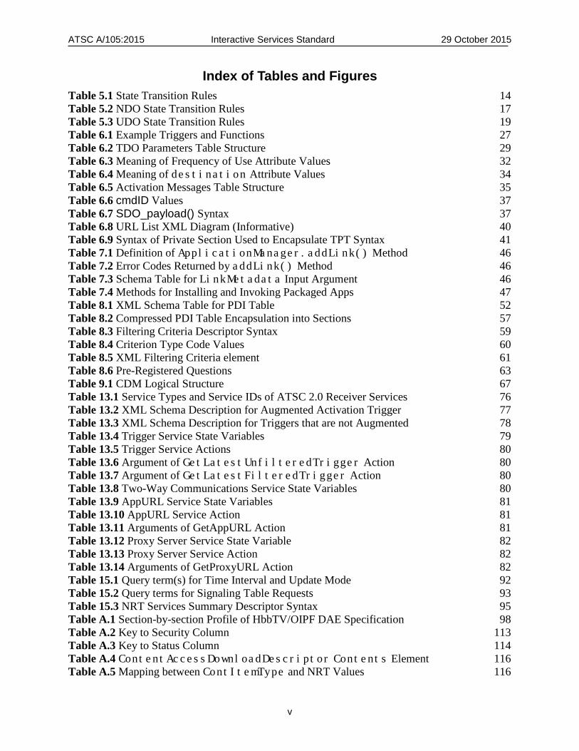
Index of Tables and Figures Table 5.1 State Transition Rules 14 Table 5.2 NDO State Transition Rules 17 Table 5.3 UDO State Transition Rules 19 Table 6.1 Example Triggers and Functions 27 Table 6.2 TDO Parameters Table Structure 29 Table 6.3 Meaning of Frequency of Use Attribute Values 32 Table 6.4 Meaning of destination Attribute Values 34 Table 6.5 Activation Messages Table Structure 35 Table 6.6 cmdID Values 37 Table 6.7 SDO_payload() Syntax 37 Table 6.8 URL List XML Diagram (Informative) 40 Table 6.9 Syntax of Private Section Used to Encapsulate TPT Syntax 41 Table 7.1 Definition of ApplicationManager.addLink() Method 46 Table 7.2 Error Codes Returned by addLink() Method 46 Table 7.3 Schema Table for LinkMetadata Input Argument 46 Table 7.4 Methods for Installing and Invoking Packaged Apps 47 Table 8.1 XML Schema Table for PDI Table 52 Table 8.2 Compressed PDI Table Encapsulation into Sections 57 Table 8.3 Filtering Criteria Descriptor Syntax 59 Table 8.4 Criterion Type Code Values 60 Table 8.5 XML Filtering Criteria element 61 Table 8.6 Pre-Registered Questions 63 Table 9.1 CDM Logical Structure 67 Table 13.1 Service Types and Service IDs of ATSC 2.0 Receiver Services 76 Table 13.2 XML Schema Description for Augmented Activation Trigger 77 Table 13.3 XML Schema Description for Triggers that are not Augmented 78 Table 13.4 Trigger Service State Variables 79 Table 13.5 Trigger Service Actions 80 Table 13.6 Argument of GetLatestUnfilteredTrigger Action 80 Table 13.7 Argument of GetLatestFilteredTrigger Action 80 Table 13.8 Two-Way Communications Service State Variables 80 Table 13.9 AppURL Service State Variables 81 Table 13.10 AppURL Service Action 81 Table 13.11 Arguments of GetAppURL Action 81 Table 13.12 Proxy Server Service State Variable 82 Table 13.13 Proxy Server Service Action 82 Table 13.14 Arguments of GetProxyURL Action 82 Table 15.1 Query term(s) for Time Interval and Update Mode 92 Table 15.2 Query terms for Signaling Table Requests 93 Table 15.3 NRT Services Summary Descriptor Syntax 95 Table A.1 Section-by-section Profile of HbbTV/OIPF DAE Specification 98 Table A.2 Key to Security Column 113 Table A.3 Key to Status Column 114 Table A.4 ContentAccessDownloadDescriptor Contents Element 116 Table A.5 Mapping between ContItemType and NRT Values 116
ATSC A/105:2015 Interactive Services Standard 29 October 2015
vi
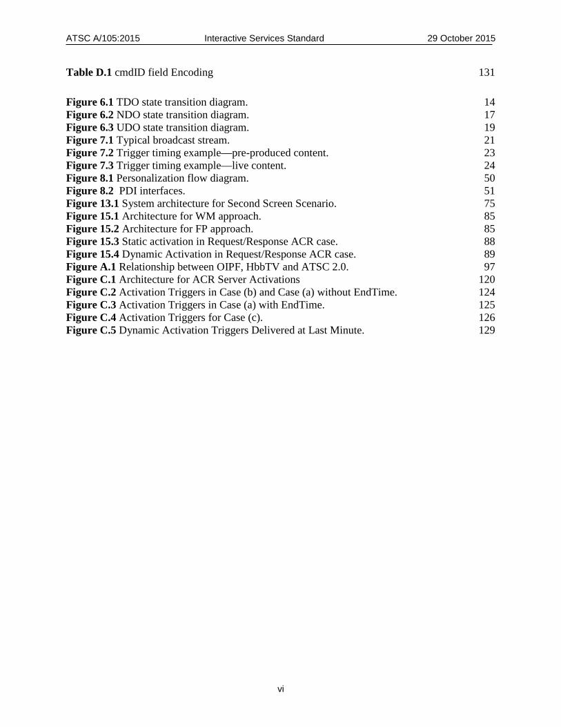
Table D.1 cmdID field Encoding 131 Figure 6.1 TDO state transition diagram. 14 Figure 6.2 NDO state transition diagram. 17 Figure 6.3 UDO state transition diagram. 19 Figure 7.1 Typical broadcast stream. 21 Figure 7.2 Trigger timing example—pre-produced content. 23 Figure 7.3 Trigger timing example—live content. 24 Figure 8.1 Personalization flow diagram. 50 Figure 8.2 PDI interfaces. 51 Figure 13.1 System architecture for Second Screen Scenario. 75 Figure 15.1 Architecture for WM approach. 85 Figure 15.2 Architecture for FP approach. 85 Figure 15.3 Static activation in Request/Response ACR case. 88 Figure 15.4 Dynamic Activation in Request/Response ACR case. 89 Figure A.1 Relationship between OIPF, HbbTV and ATSC 2.0. 97 Figure C.1 Architecture for ACR Server Activations 120 Figure C.2 Activation Triggers in Case (b) and Case (a) without EndTime. 124 Figure C.3 Activation Triggers in Case (a) with EndTime. 125 Figure C.4 Activation Triggers for Case (c). 126 Figure C.5 Dynamic Activation Triggers Delivered at Last Minute. 129

ATSC A/105:2015 Interactive Services Standard 29 October 2015
ATSC Standard: Interactive Services Standard (A/105:2015)
1. SCOPE This Standard describes the ATSC Interactive Services Standard (ISS). The Interactive Services system allows the broadcaster to connect broadcast programming with additional services related to that programming. Central to this system are Declarative Objects (DOs) providing the user’s interactive experience. Changes to the life-cycle state of Declarative Objects (for example to launch or kill a DO) can be initiated and changed by both broadcasters and viewers. The system provides for the extension of these services to second screens and provides for delivery of needed resources via the Internet path. In addition to services already part of traditional terrestrial broadcast television, services described in the present standard include personalization, service usage reporting, receiver access to web-based servers, and support for automatic content recognition.
References to “ATSC 2.0” in the present document correspond to the use of these protocols in the context of the ATSC 2.0 standard specified in A/107 [23].
1.1 Introduction This Standard was prepared by the Advanced Television Systems Committee (ATSC) Technology and Standards Group (TG1) Specialist Group on Data Broadcast. It was approved by TG1 as a Candidate Standard on 18 October 2013 and as a Proposed Standard on [date], and finally by the full ATSC membership of the ATSC on [date].
1.2 Organization This document is organized as follows:
• Section 1 – Outlines the scope of this document and provides a general introduction. • Section 2 – Lists references and applicable documents. • Section 3 – Defines terms, acronyms, abbreviations and XML conventions. • Section 4 – Provides a system overview • Section 5 – Specifies the interactivity service model • Section 6 – Specifies application lifecycle and related aspects • Section 6 – Specifies signaling of TDO properties and events • Section 7 – Specifies the execution environment for applications • Section 8 – Specifies personalization features • Section 9 – Specifies usage measurement and reporting features • Section 10 – Specifies parental guidance controls • Section 11– Specifies broadcaster notifications • Section 12 – Specifies links and packaged applications • Section 13 – Specifies second screen support features • Section 14 – Specifies the support for delivery of services over other interfaces • Section 15 – Specifies Internet delivery of signaling and announcements • Annex A – Specifies the Declarative Application Environment profile • Annex B – Provides an API use case
ATSC A/105:2015 Interactive Services Standard 29 October 2015
2
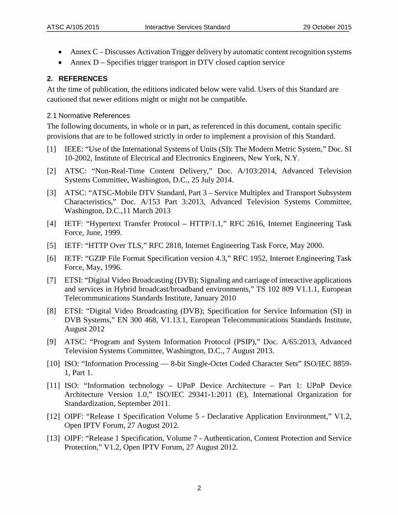
• Annex C – Discusses Activation Trigger delivery by automatic content recognition systems • Annex D – Specifies trigger transport in DTV closed caption service
2. REFERENCES At the time of publication, the editions indicated below were valid. Users of this Standard are cautioned that newer editions might or might not be compatible.
2.1 Normative References The following documents, in whole or in part, as referenced in this document, contain specific provisions that are to be followed strictly in order to implement a provision of this Standard. [1] IEEE: “Use of the International Systems of Units (SI): The Modern Metric System,” Doc. SI
10-2002, Institute of Electrical and Electronics Engineers, New York, N.Y. [2] ATSC: “Non-Real-Time Content Delivery,” Doc. A/103:2014, Advanced Television
Systems Committee, Washington, D.C., 25 July 2014. [3] ATSC: “ATSC-Mobile DTV Standard, Part 3 – Service Multiplex and Transport Subsystem
Characteristics,” Doc. A/153 Part 3:2013, Advanced Television Systems Committee, Washington, D.C.,11 March 2013
[4] IETF: “Hypertext Transfer Protocol – HTTP/1.1,” RFC 2616, Internet Engineering Task Force, June, 1999.
[5] IETF: “HTTP Over TLS,” RFC 2818, Internet Engineering Task Force, May 2000. [6] IETF: “GZIP File Format Specification version 4.3,” RFC 1952, Internet Engineering Task
Force, May, 1996. [7] ETSI: “Digital Video Broadcasting (DVB); Signaling and carriage of interactive applications
and services in Hybrid broadcast/broadband environments,” TS 102 809 V1.1.1, European Telecommunications Standards Institute, January 2010
[8] ETSI: “Digital Video Broadcasting (DVB); Specification for Service Information (SI) in DVB Systems,” EN 300 468, V1.13.1, European Telecommunications Standards Institute, August 2012
[9] ATSC: “Program and System Information Protocol (PSIP),” Doc. A/65:2013, Advanced Television Systems Committee, Washington, D.C., 7 August 2013.
[10] ISO: “Information Processing — 8-bit Single-Octet Coded Character Sets” ISO/IEC 8859-1, Part 1.
[11] ISO: “Information technology – UPnP Device Architecture – Part 1: UPnP Device Architecture Version 1.0,” ISO/IEC 29341-1:2011 (E), International Organization for Standardization, September 2011.
[12] OIPF: “Release 1 Specification Volume 5 - Declarative Application Environment,” V1.2, Open IPTV Forum, 27 August 2012.
[13] OIPF: “Release 1 Specification, Volume 7 - Authentication, Content Protection and Service Protection,” V1.2, Open IPTV Forum, 27 August 2012.

ATSC A/105:2015 Interactive Services Standard 29 October 2015
3
[14] CEA: “Digital Television (DTV) Closed Captioning, CEA-708-E, Consumer Electronics Association, June 2013.
[15] CEA: “Web-based Protocol and Framework for Remote User Interface on UPnP™ Networks and the Internet (Web4CE),” CEA-2014-A, Consumer Electronics Association, 28 August, 2008.
[16] ETSI: “Hybrid Broadcast Broadband TV,” TS 102 796 V1.2.1, European Telecommunications Standards Institute, November 2012, with the following errata applied: ETSI TS 102 796 v1.2.1 Errata 2, 7th August 2014, http://hbbtv.org/pages/about_hbbtv/TS102796-v121-errata-2.pdf.
[17] ETSI: “Digital Video Broadcasting (DVB); Uniform Resource Identifiers (URI) for DVB Systems,” TS 102 851, V1.2.1 (2011-04), European Telecommunications Standards Institute, April 2011.
[18] IETF: “Uniform Resource Identifiers (URI): Generic Syntax,” RFC 3986, January, 2005. [19] ISO: “International Standard, Information technology – Generic coding of moving pictures
and associated audio information: systems.” ISO/IEC IS 13818-1:2007 (E) International Organization for Standardization, May 2007
[20] W3C: “Widget Packaging and XML Configuration,” World Wide Web Consortium, September 2011. http://www.w3.org/TR/2011/REC-widgets-20110927.
[21] W3C: “Packaged Web Apps (Widgets) - Packaging and XML Configuration (Second Edition),” W3C Recommendation, World Wide Web Consortium, 27 November 2012.
[22] ATSC: “Security and Service Protection,” Doc. A/106, Advanced Television Systems Committee, Washington, D.C., 28 September 2015.
2.2 Informative References The following documents contain information that may be helpful in applying this Standard.
[23] ATSC: “ATSC 2.0 Standard,” Doc. A/107, Advanced Television Systems Committee, Washington, D.C., 15 June 2015.
[24] IETF: “Known Issues and Best Practices for the Use of Long Polling and Streaming in Bidirectional HTTP,” RFC 6202, April 2011.
[25] IETF: “Augmented BNF for Syntax Specifications: ABNF,” RFC 5234, January, 2008. [26] W3C: “Web IDL,” Candidate Recommendation, World Wide Web Consortium, 19 April,
2012 http://www.w3.org/TR/WebIDL/.
3. DEFINITIONS With respect to definition of terms, abbreviations, and units, the practice of the Institute of Electrical and Electronics Engineers (IEEE) as outlined in the Institute’s published standards [1] shall be used. Where an abbreviation is not covered by IEEE practice or industry practice differs from IEEE practice, the abbreviation in question will be described in Section 3.3 of this document.
3.1 Compliance Notation This section defines compliance terms for use by this document:
ATSC A/105:2015 Interactive Services Standard 29 October 2015
4
shall – This word indicates specific provisions that are to be followed strictly (no deviation is permitted).
shall not – This phrase indicates specific provisions that are absolutely prohibited. should – This word indicates that a certain course of action is preferred but not necessarily
required. should not – This phrase means a certain possibility or course of action is undesirable but not
prohibited.
3.2 Treatment of Syntactic Elements This document contains symbolic references to syntactic elements used in the audio, video, and transport coding subsystems. These references are typographically distinguished by the use of a different font (e.g., restricted), may contain the underscore character (e.g., sequence_end_code) and may consist of character strings that are not English words (e.g., dynrng). 3.2.1 Reserved Elements One or more reserved bits, symbols, fields, or ranges of values (i.e., elements) may be present in this document. These are used primarily to enable adding new values to a syntactical structure without altering its syntax or causing a problem with backwards compatibility, but they also can be used for other reasons.
The ATSC default value for reserved bits is ‘1’. There is no default value for other reserved elements. Use of reserved elements except as defined in ATSC Standards or by an industry standards setting body is not permitted. See individual element semantics for mandatory settings and any additional use constraints. As currently-reserved elements may be assigned values and meanings in future versions of this Standard, receiving devices built to this version are expected to ignore all values appearing in currently-reserved elements to avoid possible future failure to function as intended.
3.3 Acronyms and Abbreviation The following acronyms and abbreviations are used within this document. ABNF – Augmented Backus-Naur Form ACR – Automatic Content Recognition AG – Application Gateway AIT – Application Information Table AMT – Activation Messages Table API – Application Programming Interface ATSC – Advanced Television Systems Committee A/V – Audio/Video CADD – Content Access Download Descriptor CC – Closed Captioning CDM – Consumption Data Message CDU – Consumption Data Unit CEA – Consumer Electronics Association CRID – Content Reference ID (as defined by TV Anytime TM) CSS – Cascading Style Sheets CVCT – Cable Virtual Channel Table
ATSC A/105:2015 Interactive Services Standard 29 October 2015
5
DAE – Declarative Application Environment DO – Declarative Object DOM – Document Object Model DRM – Digital Rights Management DTV – Digital Television DVB – Digital Video Broadcast EIT – Event Information Table ETSI – European Telecommunications Standards Institute ETT – Extended Text Table FDT – File Description Table FLUTE – File Delivery over Unidirectional Transport FP – Fingerprinting GPS – Global Positioning System HbbTV – Hybrid broadband broadcast Television HTTP – Hypertext Transfer Protocol HTTP/S – Hypertext Transfer Protocol Secure ID – Identification IANA – Internet Assigned Numbers Authority IG IMS Gateway IEC – International Electrotechnical Commission IMS – IP Multimedia Subsystem IP – Internet Protocol IPTV – Internet Protocol Television ISO – International Organization for Standardization iTV – Interactive Television MIME – Multipurpose Internet Mail Extensions (now called Media Types) MVPD – Multichannel Video Programming Distributor NDO – NRT Declarative Object NRT – Non-Real Time NRT-IT – Non-Real-Time Information Table OMA BCAST – Open Mobile Alliance Broadcast Mobile Services Enabler Suite OIPF – Open IPTV Forum OITF – Open IPTV Terminal Function PDI – Profile, Demographics, and Interests PDI-A – Answer to a PDI question PDI-FC – PDI Filter Criteria PDI-Q – PDI question PIT – Purchase Information Table PSIP – Program and System Information Protocol PTCT – Purchase Terms and Channel Table PVR – Personal Video Recorder SD&S – Service Discovery and Selection SDO – Standards Developing Organization

ATSC A/105:2015 Interactive Services Standard 29 October 2015
6
SI – System Information SMT – Service Map Table SSC – Service Signaling Channel SSL – Secure Sockets layer STB – Set-top Box SVG – Scalable Vector Graphics TDO – Triggered Declarative Object TFT – Text Fragment Table TLS – Transport Layer Security TPT – TDO Parameters Table TVCT – Terrestrial Virtual Channel Table UDO – Unbound Declarative Object UI – User Interface UPnP – Universal Plug and Play URCR – Usage Reporting-Capable Receiver URI – Uniform Resource Identifier URL – Uniform Resource Locator UTC – Coordinated Universal Time VC – Virtual Channel VCT – Virtual Channel Table (either TVCT or CVCT) W3C – World Wide Web Consortium WM – Watermarking XML – eXtensible Markup Language
3.4 Terms The following terms are used within this document. reserved – Set aside for future use by a Standard. Trigger – A signaling element whose function is to identify signaling and establish timing of
playout of interactive events, as normatively defined in Section 7. Media Time – A parameter referencing a point in the playout of an audio/video or audio content
item.
3.5 Extensibility This Standard is designed to be extensible via both backward compatible mechanisms and by replacement syntactical mechanisms that are not backward compatible. It also establishes means to explicitly signal collections of components to establish services with various characteristics. The enumeration of the set of components that can be used to present a service is established to enable different combinations of the defined components to be offered without altering this standard. 3.5.1 Backward-compatible Extensibility Mechanisms The backward compatible mechanisms are: Table length extensions – Future amendments to this Standard may include new fields at the ends
of certain tables. Tables that may be extensible in this way include those in which the last byte
ATSC A/105:2015 Interactive Services Standard 29 October 2015
7
of the field may be determined without use of the section_length field. Such an extension is a backwards compatible addition.
Definition of reserved values – Future amendments to this Standard may establish meaning for fields that are asserted to be “reserved” in a table’s syntax, semantic or schema in the initial release. Such an extension is a backwards compatible addition due to the definition of “reserved.”
Descriptor length extensions – Future amendments to this Standard may include new fields at the ends of certain descriptors. Descriptors extensible in this way include those in which the last byte of the last currently defined field may be determined without the use of the descriptor_length field.
New descriptor types – Future amendments to this Standard may define new types of descriptors not recognized or supported by existing receiving devices. A descriptor whose descriptor_tag identifies a type not recognized by a particular receiver is expected to be ignored. Descriptors can be included in certain specified places within tables, subject to certain restrictions. Descriptors may be used to extend data represented as fixed fields within the tables. They make the protocol very flexible since they can be included only as needed. New descriptor types can be standardized and included without affecting receivers that have not been designed to recognize and process the new types.
3.5.2 Non-backward-compatible Extensibility Mechanisms Tables and schema that can be changed in a non-compatible manner each contain a field labeled major version (or major version) in order to explicitly signal their syntax. More than one instance (each with a different major version) can be expected to be present wherever such tables or schema are used. 3.5.3 Extensions with unknown compatibility This standard establishes a general signaling approach that enables new combinations of components to be transmitted that define a new or altered service offering. They, of course, are not “ATSC 2.0,” even though they are enabled by the service signaling in this standard. Receiver support for such sets is unknown and labeling of such sets of extensions to the service signaling established herein is the responsibility of the document establishing a given set of capabilities. 3.5.4 Descriptor Processing Considerations The descriptors used in “descriptor loops” in tables in this Standard have the format: type (descriptor_tag), length (descriptor_length), and data, as specified in the MPEG-2 Systems Standard ISO/ITU 13818-1 [19]. These “descriptor loops” indicate that zero, one or more descriptors are carried in that position in the stream. For many descriptor loops, certain descriptors are required and others are optional. However, these requirements specify descriptors which are required to or optionally may be carried in a particular descriptor loop. There are a large number of reserved and user-defined descriptor types which may be in private usage, or may be standardized in later versions of a standard referenced by this standard or this standard itself. 3.5.4.1 Processing Descriptor Loops Descriptor loops are collections of descriptors. In order to parse the transport stream, it is necessary to parse the descriptor_tag and descriptor_length, and subsequently either process the content of the descriptor or discard the number of bytes indicated by the descriptor_length field from the transport stream and proceed with the next entry in the descriptor loop (if any).

ATSC A/105:2015 Interactive Services Standard 29 October 2015
8
3.5.4.2 Treatment of Descriptor Length The length of each descriptor in a descriptor loop is exclusively described by the descriptor_length field. There are certain descriptors that have multiple allowable lengths. There are descriptors with descriptor_length of zero. Receivers are expected to be able to parse (or skip, as appropriate) descriptors of zero length. Receivers are expected to be able to parse (or skip, as appropriate) descriptors with varying length. Receivers are expected to be able to parse (or skip, as appropriate) descriptors with nonzero, but unexpected length (where length is either larger or smaller than expected). 3.5.4.3 Treatment of Unrecognized Descriptor Types For the reason discussed above, descriptors have a common header (descriptor_tag and descriptor_length) which devices can use to identify descriptors and process them (if they are a known type). However, unrecognized descriptors (either unrecognized in the location found or otherwise) are not errors. Emission, processing and reception devices are expected to silently ignore descriptors that they do not process. 3.5.4.4 Descriptor Order within a Descriptor Loop The collection of descriptors carried in a descriptor loop is an unordered set. No information is provided by the fact that a particular descriptor is placed before or after another within a descriptor loop.
3.6 XML Schema and Namespace A number of data structures that appear in this standard are defined as XML documents. The syntax of these documents is specified in accompanying XML schemas with namespaces of form:
http://www.atsc.org/XMLSchemas/iss/iss-<topic>-1
The <topic> term indicates the part of the standard to which the XML schema applies. The <topic> terms used in this standard are:
• tpt – schema for the TPT (TDO Parameters Table) and related XML documents • pdi – schema for XML documents related to PDI (Preferences, Demographics and
Interests) specifications • cdm – schema for the CDM (Consumption Data Message) that is utilized for service usage
reporting • cadd – schema for extension of OIPF ContItemType to include Expiration element • misc – schema for XML documents other than those in the four above categories The number “1” at the end of the namespace designation indicates that the major version
number of the schema is “1”. Future updates to this standard could result in XML schemas with a higher major version number.
For this version of this standard, the “schema” element of each XML schema contains a “version” attribute set to the value “1.0”, indicating that the major version number of the schema is “1”, and the minor version number of the schema is “0”.
Decoders of any of the XML instance documents specified in this standard are expected to ignore any documents that have a major version number higher than that of the version they are designed to decode. They are expected to decode any documents that have a major version number no higher than that of the version they are designed to decode, even if the minor version number is higher than the minor version number of the version they are designed to decode, but they should

ATSC A/105:2015 Interactive Services Standard 29 October 2015
9
follow the “must ignore” rule. That is, they should ignore any elements or attributes they do not recognize, rather than treating them as errors.
The XML schema files that provide the XML schema definitions for this version of this standard can be found http://www.atsc.org/.
While the indicated XML schema definitions provide the normative syntax of the data structures, informative schema tables are used in this standard to describe the syntax in a more illustrative way. In the event of any discrepancy between the schema tables that appear in this standard and the schema definitions that appear in the XML schema document, the schema files in the XML schema files shall take precedence.
4. INTERACTIVE SERVICES MODEL Three contexts for interactivity are supported in this standard and related ATSC standards:
• Triggered interactive adjunct data services (defined in Section 4.1 below) • Other interactive NRT services • Interactive applications not bound to a service In each case the interactivity is provided by Declarative Objects (DOs) that conform to the
specifications in Sections 5 and 7 of this standard. The term “Triggered Declarative Object” (TDO) is used to designate a Declarative Object that
has been launched by a Trigger in a Triggered interactive adjunct data service, or a DO that has been launched by a DO that has been launched by a Trigger, and so on iteratively.
The term “NRT Declarative Object” (NDO) is used to designate a Declarative Object that has been launched as part of an NRT service that is not a Triggered interactive data service.
The term “Unbound Declarative Object” (UDO) is used to designate a Declarative Object that is not bound to a service, such as a Packaged App or a DO launched by a Link, as specified in Section 12 of this standard, or a DO that has been launched by such a DO, and so on iteratively.
4.1 Triggered Interactive Adjunct Data Services The underlying service model for Triggered interactive adjunct data services in a fixed broadcast shall be the adjunct NRT service model specified for fixed broadcasts in Section 6 of ATSC A/103 [2], with adaptations as specified in the remainder of this sub-section to accommodate the special needs of Triggered interactive adjunct data services. This framework supports ATSC audio/video virtual channels in an MPEG-2 transport stream with adjunct NRT services in IP sub-domains of the channels.
Virtual channels containing a Triggered interactive adjunct data service may omit the SMT which is usually required for a virtual channel containing NRT data services, unless files for the service are being delivered in the broadcast stream (in which case the SMT is needed to provide the parameters of the FLUTE session or sessions of the service) or more than one adjunct data service is present in the broadcast stream (in which case the SMT is needed to provide the parameters of the other service, or to distinguish between the two services if the other service is also a Triggered interactive adjunct data service).
Signaling for the content items of a Triggered interactive adjunct data service shall be provided by TDO Parameters Tables (TPTs), as specified in Section 6 of this standard, rather than by the NRT-IT mechanism used for other NRT services.
An NRT service always has an associated “NRT consumption model” that defines the download, update, launch, suspend, resume and exit behavior of the content items in the service.
ATSC A/105:2015 Interactive Services Standard 29 October 2015
10
The NRT consumption model used for Triggered interactive adjunct data services shall be the “Triggered” consumption model, as specified in the remainder of this sub-section.
A virtual channel is said to be “selected” on a receiving device when it has been selected for presentation to a viewer. This is analogous to being “tuned to” an analog TV channel. In the event that more than one virtual channel can be selected by a receiver at the same time, for example in a picture-in-picture or split-screen display, one of the selected channels shall always be considered the “primary” channel. An interactive adjunct data service shall be considered to be selected when the virtual channel containing it is the only channel selected for presentation, or when more than one virtual channel is selected for presentation, and the virtual channel containing the interactive adjunct data service is the primary channel.
The broadcaster’s intent for the downloading and updating by a receiver of the content items in a selected NRT service with the “Triggered” consumption model is the following:
• Download each TDO of the service into cache as soon as it is available – where “available” means that the TDO has been announced in a TPT delivered to the receiver – unless the TDO is already available in the receiver cache. This applies to all TDOs, whether available via the broadcast or via the Internet, or both.
• Download any updated versions of TDOs into cache if and when they become available. • Download other content items used by TDOs into cache as soon as they are announced in
a TPT delivered to the receiver, unless they are real-time data feeds (content items which are being continuously updated with new versions). When a TDO is ready to start receiving a real-time data feed, it will request the content item using XMLHttpRequest. As soon as it gets a version of the content item, it will issue another request to get the next version. The receiver is expected to download the successive versions as specified in Section 5.3 of ATSC A/103 [2], and respond to the requests with a new version each time it receives one.
The expected launch, suspend, resume and exit behavior of TDOs is specified in Section 5.1 of this standard.
4.2 Interactivity in Stand-Alone NRT Services The service model for stand-alone NRT services containing interactive content items is the service model for all stand-alone NRT services specified in ATSC A/103 [2].
The expected download, update, and launch behavior of NDOs depends on the NRT consumption model of the NRT service containing them, and their role in the service. See ATSC A/103 [2] for details of the defined consumption models. The expected suspend, resume and exit behavior of NDOs is specified in Section 5.2 of this standard.
4.3 Unbound Interactive Applications UDOs in the form of Packaged Apps are expected to be downloaded when a user requests that they be installed on the receiver, as specified in Section 12 of this standard. They are expected to be launched when a user requests that they be launched. They are updated only when a user requests that an update be installed.
Links to UDOs on remote servers can be installed on a receiver, as specified in Section 12 of this standard. Such UDOs are expected to be downloaded and launched when a user requests that they be launched. When a user requests that such a UDO be launched, it is expected that the remote server will provide the most up-to-date version.
ATSC A/105:2015 Interactive Services Standard 29 October 2015
11
The expected suspend, resume and exit behavior of UDOs is specified in Section 5.3 of this standard.
5. APPLICATION MODEL As used in this section, the word “application” refers to a Declarative Object. An application can be a Triggered Declarative Object (TDO), an NRT Declarative Object (NDO), or an Unbound Declarative Object (UDO), as these terms are defined in Section 4 of this standard. (These are all special cases of NRT content items.) To “execute” or “launch” an application means to begin presenting it (which includes executing scripts that are part of it, if any).
An application can consist of a collection of individual files, or it can be packaged as a ZIP archive. If an application is packaged as a ZIP archive, then the ZIP archive must conform to the specifications of the W3C Packaged Web Apps Recommendation [21] as specified in Section 5.5.1 of A/103 [2] (since it falls into the category of NRT content items that need to have an identified “start” file).
A TDO is a unique type of NRT content item in terms of its signaling. A TDO is represented by a “TDO” element in a TDO Parameters Table (TPT), as specified in Section 6.3 of the present standard, rather than being represented by an entry in an NRT-IT, as specified for other types of NRT content items in Section 6.3 of A/103 [2].
The linkage between a TDO and the files that comprise the TDO is defined by URL child elements of the TDO element in the TPT. If a TDO is packaged as a ZIP archive, the TDO element shall have a single URL child element, and it shall point to the ZIP archive itself. The mechanisms defined in the W3C specification [21] shall be used to identify a “start” file within the ZIP archive that can be used to execute the TDO. If a TDO is not packaged as a ZIP archive, there shall be a URL child element for each file of the TDO, and the “entry” attribute of a URL element shall be used to identify a file as an entry point that can be used to execute the TDO. A content item that is used by a TDO is represented by a ContentItem child element of the TDO element in the TPT, and it can be handled similarly.
NDOs and UDOs are handled just like any other NRT content items. They can be linked to their files and executed as described in Sections 4.2 and 4.4 of A/103 [2].
In some situations, such as when an application begins execution by another application making a call to the createApplication() method, a URL is used to indicate the application to be executed. A description of how to use a URL to launch a content item can be found at the end of Section 4.4 of A/103 [2].
This document supports an application model in which at most one application can be executing at the same time (which can be a TDO, an NDO, or a UDO).
The first three subsections of this section define the lifecycle models for TDOs, NDOs and UDOs. The fourth subsection defines the concept of the “Application Domain” of an application.
5.1 TDO Lifecycle 5.1.1 TDO Lifecycle Overview A TDO can exist in four different states: Released, Ready, Active and Suspended. A number of different factors can cause a transition from one state to another (trigger, user action, changing channels, etc.).

ATSC A/105:2015 Interactive Services Standard 29 October 2015
12
The following sub-sections include a description of the relevant TDO signaling, an enumeration and description of the TDO states, an enumeration and description of the events which can cause TDO state transitions, and a specification of the TDO state transition rules. 5.1.2 TDO Signaling The properties of TDOs used in interactive adjunct data services are signaled in “TDO Parameter Tables” (TPTs) that are delivered to receivers as specified in Section 6 of this standard.
TDOs are activated/launched/executed by “Activation Triggers” that are delivered to receivers as specified in Section 6 of this standard.
TDOs can also activate other TDOs, which can in turn activate other TDOs, etc. 5.1.3 TDO States The following are the possible states of a TDO:
• Ready – downloaded and prepared for execution, but not yet executing • Active – executing • Suspended – temporarily suspended from execution, with its state saved • Released – not Ready, Active or Suspended A TDO is considered to be in the Released state when it is not contained in the currently
selected channel, as well as when it is contained in the currently selected channel and is not in the Ready, Active or Suspended state. A Released TDO does not hold any resources (other than possibly the local storage space needed to store the content item itself).
Irrespective of the state change descriptions in Sections 5.1.5 and 5.1.6, if a user has not consented to activation of TDOs in a virtual channel, as described in section 5.1.6 below, then all TDOs that are signaled for that virtual channel remain in the Released state when that virtual channel is selected for viewing, regardless of any Triggers that arrive. If the user withdraws consent for TDOs to be active in a virtual channel when any TDOs in that channel are in the Ready, Active or Suspended state, they all return to the Released state. If a user restores consent for TDOs to be active in a currently selected virtual channel, then the TDOs signaled in that channel become eligible to be Triggered. If a user requests that a specific TDO be terminated, as described in Section 5.1.6 below, that TDO is terminated and is not eligible to be re-activated by Triggers unless the user agrees to re-activation, but other TDOs in the channel are not affected. 5.1.4 TDO State Changing Events The following is a list of the events that can cause a change of state for a TDO:
• Tune away – User selects a virtual channel or stand-alone NRT service that is different from the virtual channel where the TDO is in the Ready, Active, or Suspended state, or user withdraws consent for TDOs to execute in the virtual channel where the TDO is in the Ready, Active or Suspended state.
• Trigger “prepare” – Device receives a trigger (in the currently selected primary virtual channel) which requests that the TDO be prepared to execute (allocate resources, load into main memory, etc.)
• Trigger “execute” – Device receives a trigger (in the currently selected primary virtual channel) which requests that the TDO be activated
• Trigger “suspend” – Device receives a trigger (in the currently selected primary virtual channel) which directs that the TDO be suspended
ATSC A/105:2015 Interactive Services Standard 29 October 2015
13
• Trigger “kill” – Device receives a trigger (in the currently selected primary virtual channel) which directs that the TDO be terminated
• API “kill” – This TDO calls the method Application.destroyApplication defined in Section 7.2.2 of the OIPF DAE specification [12], to terminate its own execution
• User “kill” – User manually requests that this TDO be terminated • Another DO activated – Another DO is activated when this TDO is active. This can happen
in three different ways: ○ Trigger can arrive that activates another TDO ○ User can manually execute a UDO ○ This TDO can call the method Application.createApplication to activate another
TDO 5.1.5 TDO State Transition Rules The rules given below describe the intended state change behavior for TDOs.
For the purpose of state transitions, a change from one virtual channel or stand-alone NRT service to another is treated as consisting of two logical phases, first an “unselection” of the current virtual channel or stand-alone NRT service and then a selection of the new virtual channel or stand-alone NRT service.
One effect of this is that if the old virtual channel and the new virtual channel both signal the same TDO, the TDO will go back to the Release state during the channel change, and it will be in its initial state when it goes to the Active state in the new channel.
When a viewer “tunes away from” (deselects) a virtual channel, any Ready, Active or Suspended TDO in the virtual channel is put into the Released state.
When a viewer “tunes to” (selects) a virtual channel, all TDOs associated with that virtual channel are initially in the Released state.
When a “prepare” trigger arrives, and the targeted TDO is in the Released state, the targeted TDO goes to the Ready state. If the targeted TDO is already in the Ready, Active or Suspended state, no state change occurs.
When an “execute” trigger arrives and the targeted TDO is not already in the Active state, the targeted TDO goes to the Active state. If the targeted TDO is already in the Active state, it remains in that state.
When a “suspend” trigger arrives and the targeted TDO is in the Active state, the targeted TDO goes to the Suspended state. If the targeted TDO is not in the Active state, no state change occurs.
When a “kill” trigger arrives and the targeted TDO is not in the Released state, the targeted TDO goes to the Released state. If the targeted TDO is already in the Released state, no state change occurs.
When a TDO in the Active state issues an Application.destroyApplication API call to terminate its own execution, it goes to the Released state.
When a user requests that a TDO in the Active state be terminated, it goes to the Released state.
If a TDO is activated when another TDO is in the Active state, the other TDO goes to the suspended state.
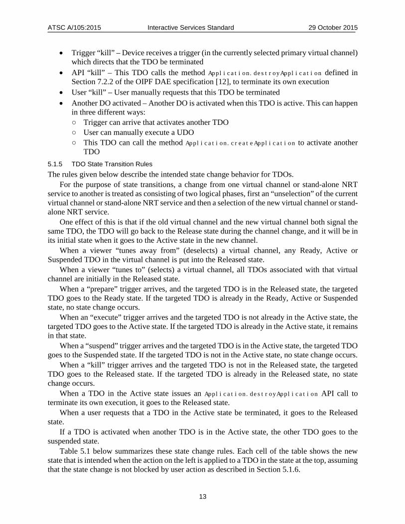
Table 5.1 below summarizes these state change rules. Each cell of the table shows the new state that is intended when the action on the left is applied to a TDO in the state at the top, assuming that the state change is not blocked by user action as described in Section 5.1.6.
ATSC A/105:2015 Interactive Services Standard 29 October 2015
14
Table 5.1 State Transition Rules
Action State
Released Ready Active Suspended
Tune away Released Released Released Released
Tune to Released N/A N/A N/A
Trig prep Ready Ready Active Suspended
Trig exec Active Active Active Active
Trig susp Released Ready Suspended Suspended
Trig kill Released Released Released Released
API kill N/A N/A Released N/A
User kill N/A N/A Released N/A
Other TDO activated Released Ready Suspended Suspended
The state diagram in Figure 6.1 illustrates the state transitions for a TDO.
Released
Active
Ready
Suspended
Trig Prep
Trig Susp
Trig Kill API Kill
Trig Exec
Tune Away
Tune Away
Tune Away
Trig Kill
Trig Kill
Other TDO
Activated
Trig Exec
Trig Exec
User Kill
Figure 6.1 TDO state transition diagram.
5.1.6 User Control of TDOs It is desirable for the user to control certain aspects of TDO behavior, in order for TDOs to be viewed as enhancing the viewing experience, rather than interfering with it. The following guidelines will help achieve this goal.
User consent should be obtained in order for TDOs to become Active. Users should be able to give consent for all TDOs to become Active, or for all TDOs in specified virtual channels to become Active, or for all TDOs to become blocked. Alternatively, users should be able to require consent on a case by case basis for TDOs in all virtual channels, or in specified virtual channels.

ATSC A/105:2015 Interactive Services Standard 29 October 2015
15
If a user requires consent on a case by case basis, then a “TDO notification” message should be displayed before a TDO is allowed to become active, and the TDO should be blocked unless and until the user indicates consent for the TDO to become active. The actual user interface for giving consent is determined by the receiver manufacturer. The format and location of the “TDO notification” message is determined by the receiver manufacturer.
There should be some mechanism to time out the “TDO notification” message, or allow the user to dismiss it, so that a user who does not consent to a TDO becoming active will not continue to be distracted by the message. However, user consent should still have the usual effect, even though the message is no longer visible.
There should be some mechanism for a user to terminate an active TDO. When a TDO is terminated in this way, it should be blocked from becoming Active again later even if additional triggers arrive that are targeted to it.
5.2 NDO Lifecycle In this subsection the term “NRT service” refers to a stand-alone NRT service. 5.2.1 NDO Lifecycle Overview An NDO can exist in three different states (Ready, Active, and Suspended). A number of different factors can cause a transition from one state to another (signaled properties of the NDO and the NRT service containing it, user actions, etc.).
The following sub-sections include a description of the NDO states, an enumeration and description of the events which can cause NDO state transitions, and a specification of the NDO state transition rules. 5.2.2 NDO States The following are the possible states of an NDO:
• Active – executing • Suspended – temporarily suspended from execution, with its state saved • Released – not Active or Suspended An NDO is considered to be in the Released state when it is not contained in the currently
selected NRT service, or when it is contained in the currently selected NRT service and is not Active or Suspended. A Released NDO does not hold any resources (other than possibly the local storage space needed to store the content item itself). 5.2.3 NDO State Changing Events The following is a list of the specific events that can cause a state change for a particular NDO:
• Tune away – User selects a virtual channel or stand-alone NRT service that is different from the NRT where this NDO is in the Active or Suspended state
• Tune to – User selects a stand-alone NRT service with “Push” or “Portal” consumption model where this NDO is the sole content item in the service, or user selects a stand-alone NRT service with “Scripted” consumption model (either Scripted Push or Scripted Portal) where this NDO is the “master” content item of the service.
• User selection – User selects this NDO for presentation when it is a content item in an NRT service with “Browse and Download” consumption model.
• API “activate” – call by another NDO to the method Application.createApplication defined in Section 7.2.2 of OIPF DAE [12], to activate this NDO.
ATSC A/105:2015 Interactive Services Standard 29 October 2015
16
Note that the call to the Application.createApplication method can occur as a result of a user action -- for example, a call by the “master” content item in a “Scripted” consumption model to start up an NDO selected by the user from a list.
• API “kill” – call by this NDO to the method Application.destroyApplication defined in section 7.2.2 of OIPF DAE [12], to terminate its own execution.
• Another DO is activated – Another DO is activated when this NDO is active. This can happen in two different ways: ○ User can manually execute a UDO ○ This NDO can call the method Application.createApplication to activate another
NDO • Another NDO is terminates itself– Under certain circumstances (described below) an NDO
goes from the Suspended state to the Active state when another NDO terminates itself. 5.2.4 NDO State Transition Rules The rules given below describe the intended state change behavior for NDOs.
For the purpose of state transitions, a change in NRT service selection is treated as consisting of two logical phases, first an “unselection” of the current NRT service and then a selection of the new virtual channel or NRT service. One effect of this is that if the old NRT service and the new NRT service both contain the same NDO, the NDO will go back to the Released state during the service change, and it will be in its initial state when it goes to the Active state in the new service.
When a user “tunes away from” (deselects) an NRT service, any Active or Suspended NDO in the virtual channel is put into the Released state.
When a user “tunes to” (selects) a Push or Portal NRT service, the content item in the service is presented. If that content item is an NDO, this means it goes to the Active state. When a user “tunes to” (selects) a Scripted Push or Scripted Portal NRT service, the “Master” content item in the service goes to the Active state.
When a user selects for presentation an NDO which is a content item in a Browse and Download NRT service, the NDO goes to the Active state.
When an Active NDO calls the Application.createApplication method, the NDO identified as the target for the call goes to the Active state. There are two forms of this call. The new NDO can be activated as a child NDO (if the createChild argument to the call is set to “true”), or it can be activated as a sibling NDO (if the createChild argument to the call is set to “false”). In the former case, the NDO making the call is suspended. In the latter case, the NDO making the call is terminated (put in the Released state).
When an Active NDO calls the Application.destroyApplication method, identifying itself as the target for the call, it goes to the Released state. If this NDO was activated by another NDO calling the Application.createApplication method, and if the createChild argument to that call was “true”, then that other NDO goes from the Suspended to the Active state after this Application.destroyApplication call.
Table 5.2 summarizes these state change rules. Each cell of the table shows the new state that is intended when the action on the left is applied to an NDO in the state at the top.

ATSC A/105:2015 Interactive Services Standard 29 October 2015
17
Table 5.2 NDO State Transition Rules
Action State
Released Active Suspended
Tune to Active(1) N/A N/A
Tune away Released Released Released
Select NDO Active N/A N/A
API activate Active N/A N/A
API kill N/A Released N/A
Other NDO activated Released Suspended or Terminated(2) Suspended
Notes: 1) If the content item in a Push or Portal NRT service is an NDO, then it becomes Active when the service is selected. If an NDO is the “Master” NDO in a Scripted Push or Scripted Portal NRT service, then it becomes Active when the service is selected. Other NDOs remain in the Released state on an NRT service selection. 2) If an NDO is activated as a child by another NDO, then the parent NDO is suspended and it will be reactivated if the child NDO terminates itself.
The state diagram in Figure 6.2 illustrates the state transitions for an NDO.
Released
Active
Suspended
API Kill
Tune Away
Tune Away
Other NDO
TerminatedTune To
Select NDO
API ActivateOther NDO
Activated
Figure 6.2 NDO state transition diagram.
5.3 UDO Lifecycle 5.3.1 UDO Lifecycle Overview A UDO can exist in three different states: Released, Active and Suspended. A number of different factors can cause a transition from one state to another.
The following sub-sections include an enumeration and description of the UDO states, an enumeration and description of the events which can cause UDO state transitions, and a specification of the UDO state transition rules.

ATSC A/105:2015 Interactive Services Standard 29 October 2015
18
5.3.2 UDO States The following are the possible states of a UDO:
• Active – executing • Suspended – temporarily suspended from execution, with its state saved • Released – not Active or Suspended A UDO is considered to be in the Released state when it is not active. A Released UDO does
not hold any resources (other than possibly the local storage space needed to store the content item itself). 5.3.3 UDO State Changing Events The following is a list of the events that can cause a state change for a particular UDO:
• User select – User selects the UDO for execution from the Packaged Apps or Links list on the receiver.
• User terminate – User asks receiver to terminate execution of a currently active UDO. • API “activate” – call by another UDO to the method Application.createApplication
defined in Section 7.2.2 of the OIPF DAE specification [12], to activate this UDO. Note that the call to the Application.createApplication method can occur as a result of a
user action; for example, a call by a UDO to start up a UDO selected by the user from a list. • API “kill” – call by this UDO to the method Application.destroyApplication defined
in Section 7.2.2 of the OIPF DAE specification [12], to terminate its own execution. • Another DO is activated – Another DO is activated when this DO is active. This can happen
in two different ways: ○ User can select a virtual channel or NRT service which causes a DO to execute ○ This NDO can call the method Application.createApplication to activate another
NDO • Another NDO is terminated – Under certain circumstances (described below) an NDO goes
from the Suspended state to the Active state when another NDO terminates itself. 5.3.4 UDO State Transition Rules The rules given below describe the intended state change behavior for NDOs.
When a user selects a UDO for execution, that UDO goes to the Active state. When a user indicates that the receiver should terminate a UDO, that UDO and its ancestors
(if any) are put into the Released state. When an Active UDO calls the Application.createApplication method, the UDO identified
as the target for the call goes to the Active state. There are two forms of this call. The new UDO can be activated as a child UDO (if the createChild argument to the call is set to “true”), or it can be activated as a sibling UDO (if the createChild argument to the call is set to “false”). In the former case, the UDO making the call is suspended. In the latter case, the UDO making the call is terminated (put in the Released state), and the parent of the terminated UDO (if any) becomes the parent of the newly activated UDO.
When an Active UDO calls the Application.destroyApplication method, identifying itself as the target for the call, it goes to the Released state. If this UDO was activated by another UDO calling the Application.createApplication method, and if the createChild argument to that call was “true”, then that other UDO goes from the Suspended to the Active state after this Application.destroyApplication call.
ATSC A/105:2015 Interactive Services Standard 29 October 2015
19
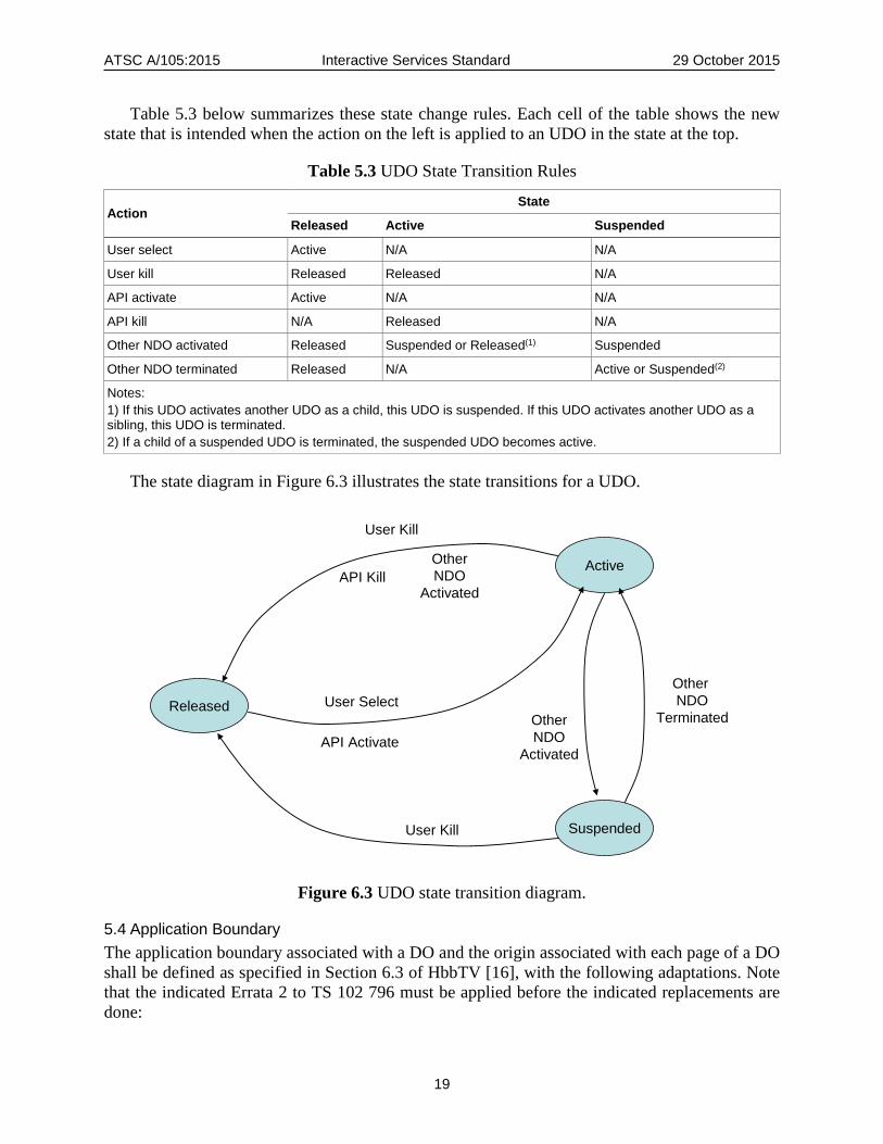
Table 5.3 below summarizes these state change rules. Each cell of the table shows the new state that is intended when the action on the left is applied to an UDO in the state at the top.
Table 5.3 UDO State Transition Rules
Action State
Released Active Suspended
User select Active N/A N/A
User kill Released Released N/A
API activate Active N/A N/A
API kill N/A Released N/A
Other NDO activated Released Suspended or Released(1) Suspended
Other NDO terminated Released N/A Active or Suspended(2)
Notes: 1) If this UDO activates another UDO as a child, this UDO is suspended. If this UDO activates another UDO as a sibling, this UDO is terminated. 2) If a child of a suspended UDO is terminated, the suspended UDO becomes active.
The state diagram in Figure 6.3 illustrates the state transitions for a UDO.
Figure 6.3 UDO state transition diagram.
5.4 Application Boundary The application boundary associated with a DO and the origin associated with each page of a DO shall be defined as specified in Section 6.3 of HbbTV [16], with the following adaptations. Note that the indicated Errata 2 to TS 102 796 must be applied before the indicated replacements are done:
Released
Active
Suspended
User Kill
User Kill
Other NDO
Activated
Other NDO
TerminatedUser Select
API Activate
API KillOther NDO
Activated
ATSC A/105:2015 Interactive Services Standard 29 October 2015
20
• Replace the words “object carousel” with “FLUTE session”. • Replace the definition of object carousels being identical with the following: “Two FLUTE
sessions shall be considered identical if they have the same source IP address and the same TSI value.
• Replace “e.g. as signaled in the AIT or XML AIT” with “e.g. as signaled in the TPT (for TDOs) or NRT-IT (for NDOs)”.
• Replace the following text: For resources loaded via DSMCC object carousel, the origin shall be the DVB
URI in the form (as defined in TS 102 851 [17] Section 6.3.1): "dvb" ":" "//" original_network_id "." transport_stream_id "." service_id "."
component_tag with:
A file delivered via FLUTE shall be ignored if its Content-Location attribute starts with "file:" or with any protocol designation that can be used to access remote Internet resources (such as "http:", "https:" or "ftp:"). The Content-Location attribute of a FLUTE file may be an absolute URI with a URI scheme of "tag" as indicated in ATSC A/103 [2] Section 5.2.7, or it may be a relative URI which can be mapped to a URI scheme of "file" as specified in ATSC A/103 [2] Section 5.2.7. (Note that when the Content-Location attribute of a FLUTE asset is a relative URI, then the path component in the "file" URL used to represent the asset according to Section 5.2.7 of ATSC A/103 [2] cannot match any possible directory path on the machine.) For resources downloaded via FLUTE, the origin shall be determined by the absolute URI in the Content-Location attribute of the resource, or by the URI determined by the mapping of a relative URI as defined in Section 5.3.7 of ATSC A/103 [2].
• Replace the words “DSM-CC” with “FLUTE session.” • Replace the description of the location where a simple_application_boundary_descriptor() may be
present with the following: ○ A simple_application_boundary_descriptor() may be present in the NRT/IT entry for the
content item representing an NDO for fixed NRT services, or an ApplicationBoundary XML element, as defined in Section 6.3 of this ATSC standard, may be present in the OMA BCAST Content fragment representing the NDO for mobile NRT services. An ApplicationBoundary element may be present as a child element of the “TDO” element in the TPT representing a TDO for Triggered interactive services.
• Omit all references to DVB URLs. The HbbTV definition of “origin” shall be as given in HbbTV [16] Section 6.3.1. The HbbTV
definition of “application boundary” shall be as given in HbbTV [16] Section 6.3.2 (references to sections are both after the indicated errata has been applied).
6. SIGNALING OF TDO PROPERTIES AND EVENTS
6.1 Introduction A typical broadcast stream consists of a sequence of TV programs. Each TV program consists of an underlying show, which is typically broken up into blocks separated by ads and/or other
ATSC A/105:2015 Interactive Services Standard 29 October 2015
21
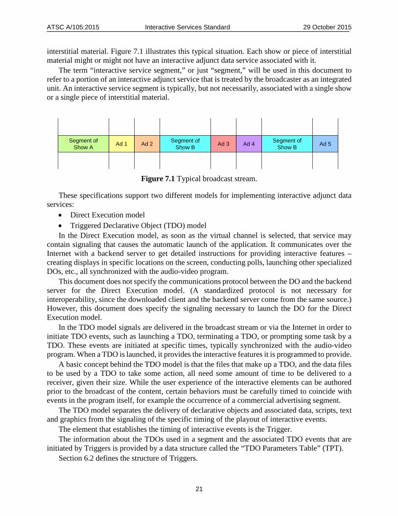
interstitial material. Figure 7.1 illustrates this typical situation. Each show or piece of interstitial material might or might not have an interactive adjunct data service associated with it.
The term “interactive service segment,” or just “segment,” will be used in this document to refer to a portion of an interactive adjunct service that is treated by the broadcaster as an integrated unit. An interactive service segment is typically, but not necessarily, associated with a single show or a single piece of interstitial material.
Figure 7.1 Typical broadcast stream.
These specifications support two different models for implementing interactive adjunct data services:
• Direct Execution model • Triggered Declarative Object (TDO) model In the Direct Execution model, as soon as the virtual channel is selected, that service may
contain signaling that causes the automatic launch of the application. It communicates over the Internet with a backend server to get detailed instructions for providing interactive features – creating displays in specific locations on the screen, conducting polls, launching other specialized DOs, etc., all synchronized with the audio-video program.
This document does not specify the communications protocol between the DO and the backend server for the Direct Execution model. (A standardized protocol is not necessary for interoperability, since the downloaded client and the backend server come from the same source.) However, this document does specify the signaling necessary to launch the DO for the Direct Execution model.
In the TDO model signals are delivered in the broadcast stream or via the Internet in order to initiate TDO events, such as launching a TDO, terminating a TDO, or prompting some task by a TDO. These events are initiated at specific times, typically synchronized with the audio-video program. When a TDO is launched, it provides the interactive features it is programmed to provide.
A basic concept behind the TDO model is that the files that make up a TDO, and the data files to be used by a TDO to take some action, all need some amount of time to be delivered to a receiver, given their size. While the user experience of the interactive elements can be authored prior to the broadcast of the content, certain behaviors must be carefully timed to coincide with events in the program itself, for example the occurrence of a commercial advertising segment.
The TDO model separates the delivery of declarative objects and associated data, scripts, text and graphics from the signaling of the specific timing of the playout of interactive events.
The element that establishes the timing of interactive events is the Trigger. The information about the TDOs used in a segment and the associated TDO events that are
initiated by Triggers is provided by a data structure called the “TDO Parameters Table” (TPT). Section 6.2 defines the structure of Triggers.
Ad 5Ad 1 Ad 2Segment ofShow A
Segment ofShow BAd 4Ad 3Segment of
Show B
ATSC A/105:2015 Interactive Services Standard 29 October 2015
22
Section 6.3 defines the structure of the TPT. Section 6.4 defines the structure of the Activation Messages Table (AMT), used for Internet
delivery of Activation Triggers for a segment in bulk. Section 6.5 defines the broadcast and Internet delivery mechanisms for Triggers, TPTs, and
the AMT and URL List which can be delivered along with a TPT. Section 6.5.2.3 defines the structure of the URL List structure, which provides the URLs of
the TPTs for one or more future segments the URL of an NRT Signaling Server that can be used to get information about stand-alone NRT services in the same broadcast stream and/or the URL of a server to which usage reports can be sent.
6.2 Triggers As specified and used in this standard, Triggers perform various timing-related signaling functions in support of interactive services. Triggers are multi-functional; depending on their structure, a particular Trigger instance can perform one or more of the following functions:
• Signal the location of a TPT (accessible via a FLUTE session in the emission stream, via an Internet server, or both);
• Indicate that interactive content for an upcoming program segment is available to be pre-loaded;
• Indicate the current Media Time of associated audio/video or audio-only content; • Reference a particular interactive event in a TPT and signal that the event is to be executed
now or at a specified future Media Time; • Indicate that accesses to an Internet server are to be spread out randomly over a specified
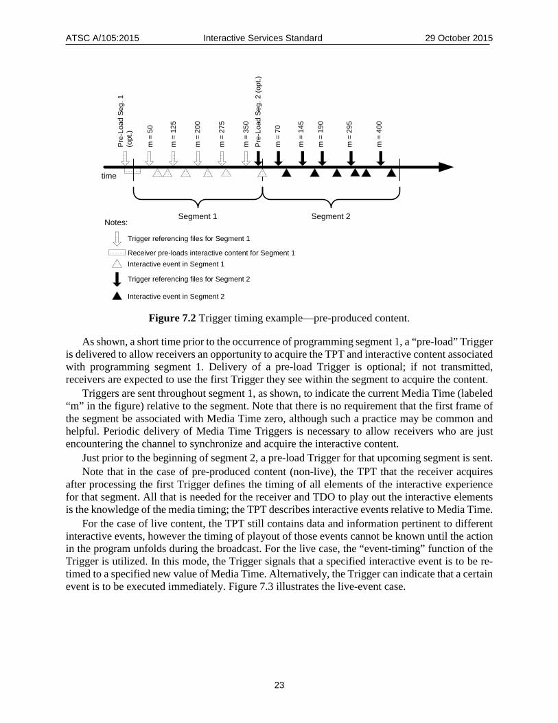
time interval in order to avoid a peak in demand. 6.2.1 Trigger Timing Example Figure 7.2 illustrates Triggers delivered in association with two programming segments. In this example, both segments are “pre-produced,” meaning that the content is not from a live broadcast; interactive elements have been added in post-production.
ATSC A/105:2015 Interactive Services Standard 29 October 2015
23
Segment 1 Segment 2
Pre-
Load
Seg
. 1
(opt
.)
m =
50
m =
125
m =
200
m =
275
m =
350
Pre-
Load
Seg
. 2 (o
pt.)
m =
70
m =
145
m =
190
m =
295
m =
400
time
Notes:
Trigger referencing files for Segment 1
Trigger referencing files for Segment 2
Receiver pre-loads interactive content for Segment 1Interactive event in Segment 1
Interactive event in Segment 2 Figure 7.2 Trigger timing example—pre-produced content.
As shown, a short time prior to the occurrence of programming segment 1, a “pre-load” Trigger is delivered to allow receivers an opportunity to acquire the TPT and interactive content associated with programming segment 1. Delivery of a pre-load Trigger is optional; if not transmitted, receivers are expected to use the first Trigger they see within the segment to acquire the content.
Triggers are sent throughout segment 1, as shown, to indicate the current Media Time (labeled “m” in the figure) relative to the segment. Note that there is no requirement that the first frame of the segment be associated with Media Time zero, although such a practice may be common and helpful. Periodic delivery of Media Time Triggers is necessary to allow receivers who are just encountering the channel to synchronize and acquire the interactive content.
Just prior to the beginning of segment 2, a pre-load Trigger for that upcoming segment is sent. Note that in the case of pre-produced content (non-live), the TPT that the receiver acquires
after processing the first Trigger defines the timing of all elements of the interactive experience for that segment. All that is needed for the receiver and TDO to play out the interactive elements is the knowledge of the media timing; the TPT describes interactive events relative to Media Time.
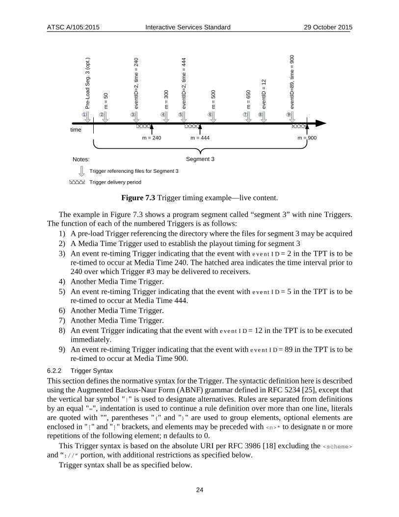
For the case of live content, the TPT still contains data and information pertinent to different interactive events, however the timing of playout of those events cannot be known until the action in the program unfolds during the broadcast. For the live case, the “event-timing” function of the Trigger is utilized. In this mode, the Trigger signals that a specified interactive event is to be re-timed to a specified new value of Media Time. Alternatively, the Trigger can indicate that a certain event is to be executed immediately. Figure 7.3 illustrates the live-event case.
ATSC A/105:2015 Interactive Services Standard 29 October 2015
24
Segment 3
Pre-
Load
Seg
. 3 (o
pt.)
m =
50
even
tID =
12
m =
300
time
Notes:
Trigger referencing files for Segment 3
m = 240
Trigger delivery period
1 2 83 4 5
m = 444
m =
500
6
m = 900
even
tID=8
9, ti
me
= 90
0
9
m =
650
7
even
tID=2
, tim
e =
240
even
tID=2
, tim
e =
444
Figure 7.3 Trigger timing example—live content.
The example in Figure 7.3 shows a program segment called “segment 3” with nine Triggers. The function of each of the numbered Triggers is as follows:
1) A pre-load Trigger referencing the directory where the files for segment 3 may be acquired 2) A Media Time Trigger used to establish the playout timing for segment 3 3) An event re-timing Trigger indicating that the event with eventID = 2 in the TPT is to be
re-timed to occur at Media Time 240. The hatched area indicates the time interval prior to 240 over which Trigger #3 may be delivered to receivers.
4) Another Media Time Trigger. 5) An event re-timing Trigger indicating that the event with eventID = 5 in the TPT is to be
re-timed to occur at Media Time 444. 6) Another Media Time Trigger. 7) Another Media Time Trigger. 8) An event Trigger indicating that the event with eventID = 12 in the TPT is to be executed
immediately. 9) An event re-timing Trigger indicating that the event with eventID = 89 in the TPT is to be
re-timed to occur at Media Time 900. 6.2.2 Trigger Syntax This section defines the normative syntax for the Trigger. The syntactic definition here is described using the Augmented Backus-Naur Form (ABNF) grammar defined in RFC 5234 [25], except that the vertical bar symbol "|" is used to designate alternatives. Rules are separated from definitions by an equal "=", indentation is used to continue a rule definition over more than one line, literals are quoted with "", parentheses "(" and ")" are used to group elements, optional elements are enclosed in "[" and "]" brackets, and elements may be preceded with <n>* to designate n or more repetitions of the following element; n defaults to 0.
This Trigger syntax is based on the absolute URI per RFC 3986 [18] excluding the <scheme> and “://” portion, with additional restrictions as specified below.
Trigger syntax shall be as specified below.
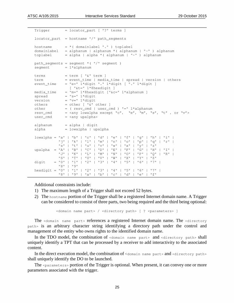
ATSC A/105:2015 Interactive Services Standard 29 October 2015
25
Trigger = locator_part [ "?" terms ] locator_part = hostname "/" path_segments hostname = *( domainlabel "." ) toplabel domainlabel = alphanum | alphanum *( alphanum | "-" ) alphanum toplabel = alpha | alpha *( alphanum | "-" ) alphanum path_segments = segment *( "/" segment ) segment = 1*alphanum terms = term [ "&" term ] term = event_time | media_time | spread | version | others event_time = "e=" 1*digit "." 1*digit [ "." 1*digit ] [ "&t=" 1*8hexdigit ] media_time = "m=" 1*8hexdigit ["&c=" 1*alphanum ] spread = "s=" 1*digit version = "v=" 1*digit others = other [ "&" other ] other = ( resv_cmd | user_cmd ) "=" 1*alphanum resv_cmd = <any lowalpha except “c”, “e”, “m”, “s”, “t” , or “v”> user_cmd = <any upalpha> alphanum = alpha | digit alpha = lowalpha | upalpha lowalpha = "a" | "b" | "c" | "d" | "e" | "f" | "g" | "h" | "i" | "j" | "k" | "l" | "m" | "n" | "o" | "p" | "q" | "r" | "s" | "t" | "u" | "v" | "w" | "x" | "y" | "z" upalpha = "A" | "B" | "C" | "D" | "E" | "F" | "G" | "H" | "I" | "J" | "K" | "L" | "M" | "N" | "O" | "P" | "Q" | "R" | "S" | "T" | "U" | "V" | "W" | "X" | "Y" | "Z" digit = "0" | "1" | "2" | "3" | "4" | "5" | "6" | "7" | "8" | "9" hexdigit = "0" | "1" | "2" | "3" | "4" | "5" | "6" | "7" | "8" | "9" | "a" | "b" | "c" | "d" | "e" | "f"
Additional constraints include: 1) The maximum length of a Trigger shall not exceed 52 bytes. 2) The hostname portion of the Trigger shall be a registered Internet domain name. A Trigger
can be considered to consist of three parts, two being required and the third being optional:
<domain name part> / <directory path> [ ? <parameters> ]
The <domain name part> references a registered Internet domain name. The <directory path> is an arbitrary character string identifying a directory path under the control and management of the entity who owns rights to the identified domain name.
In the TDO model, the combination of <domain name part> and <directory path> shall uniquely identify a TPT that can be processed by a receiver to add interactivity to the associated content.
In the direct execution model, the combination of <domain name part> and <directory path> shall uniquely identify the DO to be launched.
The <parameters> portion of the Trigger is optional. When present, it can convey one or more parameters associated with the trigger.
ATSC A/105:2015 Interactive Services Standard 29 October 2015
26
6.2.3 Trigger Parameters Optionally, a Trigger can carry parameters within a query string (the portion of the Trigger to the right of the “?”). Formats for the query string include:
• <media time>
• <media time> and <spread> • <media time> and <version> • <media time> and <version> and <spread> • <event time>
• <event time> and <spread> • <event time> and <version> • <event time> and <version> and <spread> The parameters shall be formatted according to the following rules. Per the trigger syntax,
terms following the first, if present, are each preceded by an ampersand character (“&”). <event time> – two terms, an interactive event ID designated by “e=” followed by two or three
decimal numbers with a dot (“.”) separating them, referencing the appID in the associated TPT of the TDO targeted by the event, the eventID of the specific event, and optionally the dataID of the Data element to be used for this event activation, plus an optional timing value term designated by “t=” followed by a string 1 to 8 characters in length representing a hexadecimal number indicating a new media timing for the designated event. If the “t=” part is not present, that means the timing for the designated event is the arrival time of the Trigger.
<media time> – two terms, a media timestamp term designated by “m=” followed by a character string of 1 to 8 characters in length representing a hexadecimal number indicating the current Media Time in units of milliseconds, and an optional contentID term designated by “c=” followed by a character string representing an identifier for the content currently being viewed. The contentID term is intended to support the Direct Execution model of interactive service implementation. In that model Time Base Triggers are passed in to the DO after it is launched, and the DO delivers the contentID to the backend server in order to identify the context for the interaction.
<version> – A term designated by “v=” followed by a character string of 1 to 3 characters in length representing a decimal number indicating the version of the TPT associated with this Trigger. Receivers are expected to process the version parameter to identify the need to acquire an updated TPT.
<spread> – a term designated by “s=” followed by a character string of 1 to 3 characters in length representing a decimal number indicating the number of seconds of time over which all receivers should attempt to access the Internet server identified in the Trigger. Each individual receiver is expected to derive a random time within the designated interval and delay the access request by that amount, thereby spreading in time the peak in demand that might otherwise occur at the first appearance of a Trigger at the receiver.
<other> – a term designated by a character other than "e", "E", "m", "M", "s", "S", "t", or "T", followed by the equals-sign and an alphanumeric string. Receivers are expected to disregard unrecognized terms. A Trigger containing a <media time> parameter is called a Time Base Trigger, since it is used
to establish a time base for event times. A Trigger containing an <event time> parameter is called an Activation Trigger, since it sets
an activation time for an event.
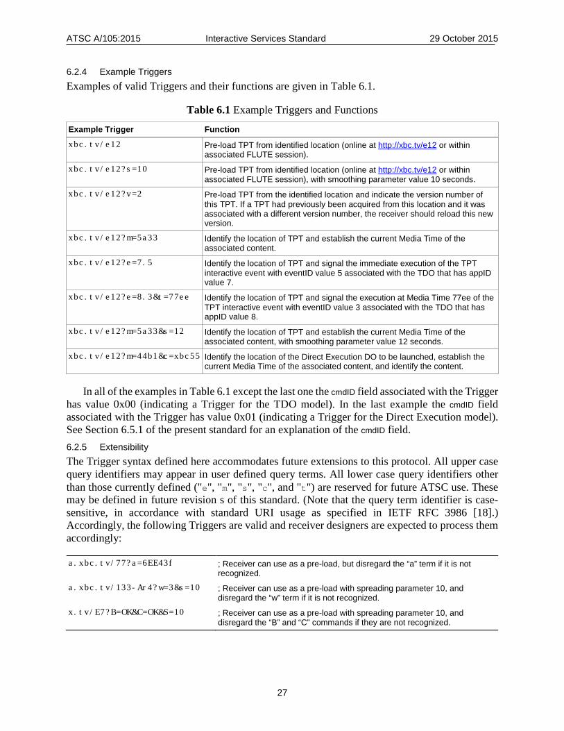
ATSC A/105:2015 Interactive Services Standard 29 October 2015
27
6.2.4 Example Triggers Examples of valid Triggers and their functions are given in Table 6.1.
Table 6.1 Example Triggers and Functions
Example Trigger Function xbc.tv/e12 Pre-load TPT from identified location (online at http://xbc.tv/e12 or within
associated FLUTE session).
xbc.tv/e12?s=10 Pre-load TPT from identified location (online at http://xbc.tv/e12 or within associated FLUTE session), with smoothing parameter value 10 seconds.
xbc.tv/e12?v=2 Pre-load TPT from the identified location and indicate the version number of this TPT. If a TPT had previously been acquired from this location and it was associated with a different version number, the receiver should reload this new version.
xbc.tv/e12?m=5a33 Identify the location of TPT and establish the current Media Time of the associated content.
xbc.tv/e12?e=7.5 Identify the location of TPT and signal the immediate execution of the TPT interactive event with eventID value 5 associated with the TDO that has appID value 7.
xbc.tv/e12?e=8.3&t=77ee Identify the location of TPT and signal the execution at Media Time 77ee of the TPT interactive event with eventID value 3 associated with the TDO that has appID value 8.
xbc.tv/e12?m=5a33&s=12 Identify the location of TPT and establish the current Media Time of the associated content, with smoothing parameter value 12 seconds.
xbc.tv/e12?m=44b1&c=xbc55 Identify the location of the Direct Execution DO to be launched, establish the current Media Time of the associated content, and identify the content.
In all of the examples in Table 6.1 except the last one the cmdID field associated with the Trigger has value 0x00 (indicating a Trigger for the TDO model). In the last example the cmdID field associated with the Trigger has value 0x01 (indicating a Trigger for the Direct Execution model). See Section 6.5.1 of the present standard for an explanation of the cmdID field. 6.2.5 Extensibility The Trigger syntax defined here accommodates future extensions to this protocol. All upper case query identifiers may appear in user defined query terms. All lower case query identifiers other than those currently defined ("e", "m", "s", "c", and "t") are reserved for future ATSC use. These may be defined in future revision s of this standard. (Note that the query term identifier is case-sensitive, in accordance with standard URI usage as specified in IETF RFC 3986 [18].) Accordingly, the following Triggers are valid and receiver designers are expected to process them accordingly:
a.xbc.tv/77?a=6EE43f ; Receiver can use as a pre-load, but disregard the “a” term if it is not recognized.
a.xbc.tv/133-Ar4?w=3&s=10 ; Receiver can use as a pre-load with spreading parameter 10, and disregard the “w” term if it is not recognized.
x.tv/E7?B=OK&C=OK&S=10 ; Receiver can use as a pre-load with spreading parameter 10, and disregard the “B” and “C” commands if they are not recognized.
ATSC A/105:2015 Interactive Services Standard 29 October 2015
28
6.3 TDO Parameters Table (TPT) A TDO Parameters Table (TPT) contains metadata about the TDOs of a segment and the Events targeted to them.
A TDO Parameters Table shall be an XML document containing a “TPT” root element that conforms to the definitions in the XML schema that has namespace
http://www.atsc.org/XMLSchemas/iss/iss-tpt-1
The definition of this schema is in a schema file accompanying this standard, as described in Section 3.5 above
While the indicated XML schema specifies the normative syntax of the TPT element, informative Table 6.2 below describes the structure of the TPT element in a more illustrative way. The definitions of the semantics of the elements and attributes in the schema appear immediately after Table 6.2.

ATSC A/105:2015 Interactive Services Standard 29 October 2015
29
Table 6.2 TDO Parameters Table Structure
Element/Attribute (with @) Card-inality Data Type Description and Value
TPT
@majorProtocolVersion 0..1 integer 0..15 Major Protocol Version, default=“1”
@minorProtocolVersion 0..1 integer 0..15 Minor Protocol version, default=“0”
@id 1 anyURI segment_id = domain_name/program_id
@tptVersion 1 unsignedByte Data version of this TPT
@expireDate 0..1 dateTime Date after which this TPT will not be used
@updatingTime 0..1 unsignedShort Time interval to check for TPT updates
@serviceID 0..1 unsignedShort NRT service_id
@baseURL 0..1 anyURI Base URL for all relative URLs in TPT
Capabilities 0..1 nrt:CapabilitiesType Essential capabilities for the segment associated with this TPT
LiveTrigger 0..1 Info on Internet live trigger delivery
@URL 1 anyURI URL of server for live triggers
@pollPeriod 0..1 unsignedByte Short polling period in seconds
TDO 1..N TDO (app) for the segment associated with this TPT
@appID 1 unsignedShort Application ID of this app, unique within the scope of this TPT
@appType 0..1 integer 0-15 Application type (default: 1=”TDO”)
@appName 0..1 string Display name (for viewer launch consent)
@globalID 0..1 anyURI Globally unique app ID
@appVersion 0..1 unsignedByte Version of this app
@cookieSpace 0..1 unsignedByte Persistent storage needed; default=0
@frequencyOfUse 0..1 integer 0..15 Code values per Table 6.3
@expireDate 0..1 dateTime Expire date for caching this app
@testTDO 0..1 boolean Flag for test app; default=”false”
@availInternet 0..1 boolean Default=”true”
@availBroadcast 0..1 boolean Default=”true”
URL 1..N anyURI App URL(s)
@entry 0..1 boolean Indicator of entry point; default = “false”
Capabilities 0..1 nrt:CapabilitiesType Essential capabilities to present this app
ApplicationBoundary 0..1 Extensions to app boundary
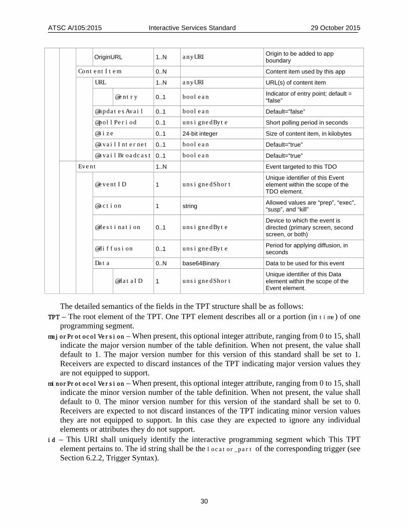
ATSC A/105:2015 Interactive Services Standard 29 October 2015
30
OriginURL 1..N anyURI Origin to be added to app boundary
ContentItem 0..N Content item used by this app
URL 1..N anyURI URL(s) of content item
@entry 0..1 boolean Indicator of entry point; default = “false”
@updatesAvail 0..1 boolean Default=”false”
@pollPeriod 0..1 unsignedByte Short polling period in seconds
@size 0..1 24-bit integer Size of content item, in kilobytes
@availInternet 0..1 boolean Default=“true”
@availBroadcast 0..1 boolean Default=“true”
Event 1..N Event targeted to this TDO
@eventID 1 unsignedShort
Unique identifier of this Event element within the scope of the TDO element.
@action 1 string Allowed values are “prep”, “exec”, “susp”, and “kill”
@destination 0..1 unsignedByte Device to which the event is directed (primary screen, second screen, or both)
@diffusion 0..1 unsignedByte Period for applying diffusion, in seconds
Data 0..N base64Binary Data to be used for this event
@dataID 1 unsignedShort Unique identifier of this Data element within the scope of the Event element.
The detailed semantics of the fields in the TPT structure shall be as follows: TPT – The root element of the TPT. One TPT element describes all or a portion (in time) of one
programming segment. majorProtocolVersion – When present, this optional integer attribute, ranging from 0 to 15, shall
indicate the major version number of the table definition. When not present, the value shall default to 1. The major version number for this version of this standard shall be set to 1. Receivers are expected to discard instances of the TPT indicating major version values they are not equipped to support.
minorProtocolVersion – When present, this optional integer attribute, ranging from 0 to 15, shall indicate the minor version number of the table definition. When not present, the value shall default to 0. The minor version number for this version of the standard shall be set to 0. Receivers are expected to not discard instances of the TPT indicating minor version values they are not equipped to support. In this case they are expected to ignore any individual elements or attributes they do not support.
id – This URI shall uniquely identify the interactive programming segment which This TPT element pertains to. The id string shall be the locator_part of the corresponding trigger (see Section 6.2.2, Trigger Syntax).
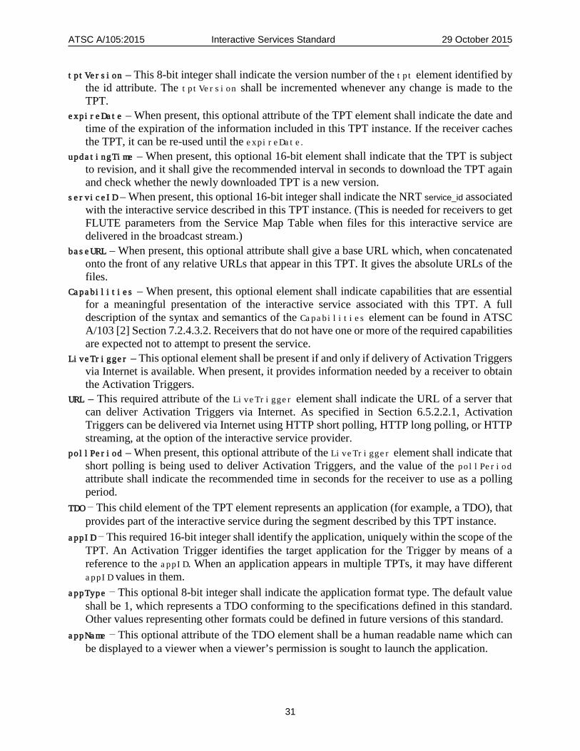
ATSC A/105:2015 Interactive Services Standard 29 October 2015
31
tptVersion – This 8-bit integer shall indicate the version number of the tpt element identified by the id attribute. The tptVersion shall be incremented whenever any change is made to the TPT.
expireDate – When present, this optional attribute of the TPT element shall indicate the date and time of the expiration of the information included in this TPT instance. If the receiver caches the TPT, it can be re-used until the expireDate.
updatingTime – When present, this optional 16-bit element shall indicate that the TPT is subject to revision, and it shall give the recommended interval in seconds to download the TPT again and check whether the newly downloaded TPT is a new version.
serviceID – When present, this optional 16-bit integer shall indicate the NRT service_id associated with the interactive service described in this TPT instance. (This is needed for receivers to get FLUTE parameters from the Service Map Table when files for this interactive service are delivered in the broadcast stream.)
baseURL – When present, this optional attribute shall give a base URL which, when concatenated onto the front of any relative URLs that appear in this TPT. It gives the absolute URLs of the files.
Capabilities – When present, this optional element shall indicate capabilities that are essential for a meaningful presentation of the interactive service associated with this TPT. A full description of the syntax and semantics of the Capabilities element can be found in ATSC A/103 [2] Section 7.2.4.3.2. Receivers that do not have one or more of the required capabilities are expected not to attempt to present the service.
LiveTrigger – This optional element shall be present if and only if delivery of Activation Triggers via Internet is available. When present, it provides information needed by a receiver to obtain the Activation Triggers.
URL – This required attribute of the LiveTrigger element shall indicate the URL of a server that can deliver Activation Triggers via Internet. As specified in Section 6.5.2.2.1, Activation Triggers can be delivered via Internet using HTTP short polling, HTTP long polling, or HTTP streaming, at the option of the interactive service provider.
pollPeriod – When present, this optional attribute of the LiveTrigger element shall indicate that short polling is being used to deliver Activation Triggers, and the value of the pollPeriod attribute shall indicate the recommended time in seconds for the receiver to use as a polling period.
TDO – This child element of the TPT element represents an application (for example, a TDO), that provides part of the interactive service during the segment described by this TPT instance.
appID – This required 16-bit integer shall identify the application, uniquely within the scope of the TPT. An Activation Trigger identifies the target application for the Trigger by means of a reference to the appID. When an application appears in multiple TPTs, it may have different appID values in them.
appType – This optional 8-bit integer shall indicate the application format type. The default value shall be 1, which represents a TDO conforming to the specifications defined in this standard. Other values representing other formats could be defined in future versions of this standard.
appName – This optional attribute of the TDO element shall be a human readable name which can be displayed to a viewer when a viewer’s permission is sought to launch the application.
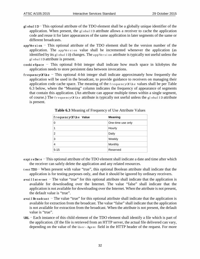
ATSC A/105:2015 Interactive Services Standard 29 October 2015
32
globalID – This optional attribute of the TDO element shall be a globally unique identifier of the application. When present, the globalID attribute allows a receiver to cache the application code and reuse it for later appearances of the same application in later segments of the same or different broadcasts.
appVersion – This optional attribute of the TDO element shall be the version number of the application. The appVersion value shall be incremented whenever the application (as identified by its globalID) changes. The appVersion attribute is typically not useful unless the globalID attribute is present.
cookieSpace – This optional 8-bit integer shall indicate how much space in kilobytes the application needs to store persistent data between invocations.
frequencyOfUse – This optional 4-bit integer shall indicate approximately how frequently the application will be used in the broadcast, to provide guidance to receivers on managing their application code cache space. The meaning of the frequencyOfUse values shall be per Table 6.3 below, where the “Meaning” column indicates the frequency of appearance of segments that contain this application. (An attribute can appear multiple times within a single segment, of course.) The frequencyOfUse attribute is typically not useful unless the globalID attribute is present.
Table 6.3 Meaning of Frequency of Use Attribute Values
frequencyOfUse Value Meaning
0 One-time use only
1 Hourly
2 Daily
3 Weekly
4 Monthly
5-15 Reserved
expireDate – This optional attribute of the TDO element shall indicate a date and time after which the receiver can safely delete the application and any related resources.
testTDO – When present with value “true”, this optional Boolean attribute shall indicate that the application is for testing purposes only, and that it should be ignored by ordinary receivers.
availInternet – The value “true” for this optional attribute shall indicate that the application is available for downloading over the Internet. The value “false” shall indicate that the application is not available for downloading over the Internet. When the attribute is not present, the default value is “true”.
availBroadcast – The value “true” for this optional attribute shall indicate that the application is available for extraction from the broadcast. The value “false” shall indicate that the application is not available for extraction from the broadcast. When the attribute is not present, the default value is “true”.
URL – Each instance of this child element of the TDO element shall identify a file which is part of the application. (If the file is retrieved from an HTTP server, the actual file delivered can vary, depending on the value of the User-Agent field in the HTTP header of the request. For more
ATSC A/105:2015 Interactive Services Standard 29 October 2015
33
details, see the row of Table A,1 in Annex A of this document on the topic of “HTTP user agent header.”)
entry – When this optional attribute of the URL element has value “true”, that indicates that the URL is an entry point for the application – i.e., a file that can be launched in order to launch the application. When it has value “false”, that indicates that the URL is not an entry point for the application. The default value when the attribute does not appear is “false.”
Capabilities – When present, this optional child element of the TDO element shall indicate capabilities that are essential for a meaningful presentation of this application. A full description of the syntax and semantics of the Capabilities element can be found in A/103 [2] Section 7.2.4.3.2. Receivers that do not have one or more of the required capabilities are expected not to attempt to present launch the application.
ApplicationBoundary – When present, this optional child element of the TDO element includes origins to be added to the application boundary of the TDO. (See Section 5.4 of the present standard for definitions, by reference, of the terms “application boundary” and “origin”.)
OriginURL – This element defines an origin that shall be added to the application boundary of the TDO.
ContentItem – This optional child element of the TDO element shall indicate a content item consisting of one or more data files that are needed by the application.
URL – Each instance of this child element of the ContentItem element shall identify a file which is part of the content item. (If the file is retrieved from an HTTP server, the actual file delivered can vary, depending on the value of the User-Agent field in the HTTP header of the request. For more details, see the row of Table A,1 in Annex A of this document on the topic of “HTTP user agent header.”)
entry – When this optional attribute of the URL element has value “true”, that indicates that the URL is an entry point for the content item – i.e., a file that can be launched in order to launch the content item. When it has value “false,” that indicates that the URL is not an entry point for the content item. The default value when the attribute does not appear is “false.”
updatesAvail – This optional Boolean attribute of the ContentItem element shall indicate whether or not the content item will be updated from time to time – i.e., whether the content item consists of static files or whether it is a real-time data feed. When the value is “true” the content item will be updated from time to time; when the value is “false” the content item will not be updated. The default value when this attribute does not appear is false.
pollPeriod – This optional attribute of the ContentItem element may be present only when the value of the updatesAvail attribute is “true”. The presence of the pollPeriod attribute shall indicate that short polling is being used to deliver Activation Triggers, and the value of the pollPeriod attribute shall indicate the recommended time in seconds for the receiver to use as a polling period.
Size – This optional attribute of the ContentItem element shall indicate the size of the content item, in kilobytes.
availInternet – The value “true” for this optional attribute shall indicate that the content item is available for downloading over the Internet. The value “false” shall indicate that the content item is not available for downloading over the Internet. When this attribute is not present, the default value is “true.”
availBroadcast – The value “true” for this optional attribute shall indicate that the content item is available for extraction from the broadcast. The value “false” shall indicate that the content
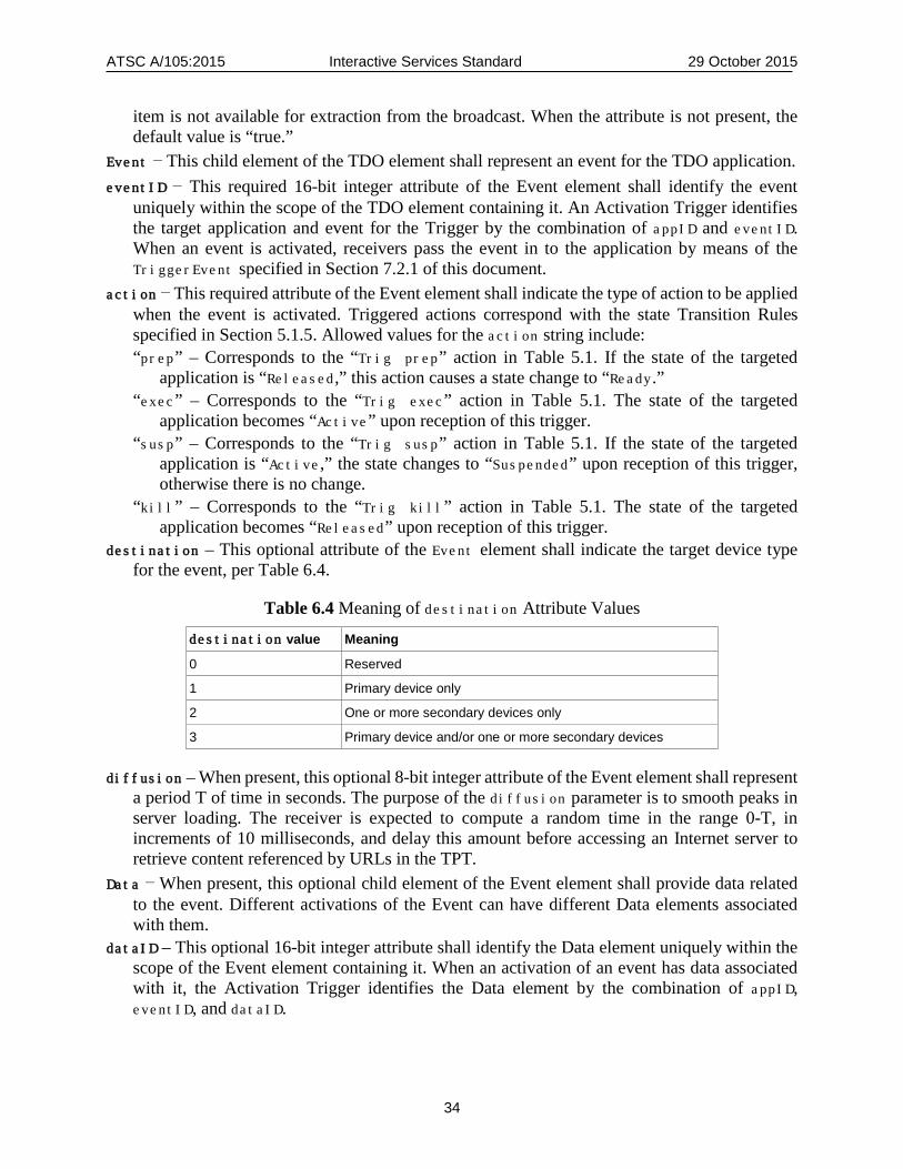
ATSC A/105:2015 Interactive Services Standard 29 October 2015
34
item is not available for extraction from the broadcast. When the attribute is not present, the default value is “true.”
Event – This child element of the TDO element shall represent an event for the TDO application. eventID – This required 16-bit integer attribute of the Event element shall identify the event
uniquely within the scope of the TDO element containing it. An Activation Trigger identifies the target application and event for the Trigger by the combination of appID and eventID. When an event is activated, receivers pass the event in to the application by means of the TriggerEvent specified in Section 7.2.1 of this document.
action – This required attribute of the Event element shall indicate the type of action to be applied when the event is activated. Triggered actions correspond with the state Transition Rules specified in Section 5.1.5. Allowed values for the action string include: “prep” – Corresponds to the “Trig prep” action in Table 5.1. If the state of the targeted
application is “Released,” this action causes a state change to “Ready.” “exec” – Corresponds to the “Trig exec” action in Table 5.1. The state of the targeted
application becomes “Active” upon reception of this trigger. “susp” – Corresponds to the “Trig susp” action in Table 5.1. If the state of the targeted
application is “Active,” the state changes to “Suspended” upon reception of this trigger, otherwise there is no change.
“kill” – Corresponds to the “Trig kill” action in Table 5.1. The state of the targeted application becomes “Released” upon reception of this trigger.
destination – This optional attribute of the Event element shall indicate the target device type for the event, per Table 6.4.
Table 6.4 Meaning of destination Attribute Values
destination value Meaning
0 Reserved
1 Primary device only
2 One or more secondary devices only
3 Primary device and/or one or more secondary devices
diffusion – When present, this optional 8-bit integer attribute of the Event element shall represent a period T of time in seconds. The purpose of the diffusion parameter is to smooth peaks in server loading. The receiver is expected to compute a random time in the range 0-T, in increments of 10 milliseconds, and delay this amount before accessing an Internet server to retrieve content referenced by URLs in the TPT.
Data – When present, this optional child element of the Event element shall provide data related to the event. Different activations of the Event can have different Data elements associated with them.
dataID – This optional 16-bit integer attribute shall identify the Data element uniquely within the scope of the Event element containing it. When an activation of an event has data associated with it, the Activation Trigger identifies the Data element by the combination of appID, eventID, and dataID.

ATSC A/105:2015 Interactive Services Standard 29 October 2015
35
6.4 Activation Messages Table (AMT) An Activation Messages Table (AMT) contains the equivalent of the Activation Triggers for a segment. It is typically generated by the content creator, and in ACR scenarios it might be delivered to receivers in lieu of individual Activation Triggers.
The Activation Messages Table shall be an XML document containing an “AMT” root element that conforms to the definition in the XML schema that has namespace.
http://www.atsc.org/XMLSchemas/iss/iss-tpt-1
The definition of this schema is in a schema file accompanying this standard, as described in Section 3.5.
While the indicated XML schema specifies the normative syntax of the AMT element, informative Table 6.5 below describes the structure of the AMT element in a more illustrative way.
Table 6.5 Activation Messages Table Structure
Element/Attribute (with @) Cardinality Data Type Description and Value AMT
@majorProtocolVersion 0..1 integer 0-15 Major protocol version, default=“1”
@minorProtocolVersion 0..1 integer 0-15 Minor protocol version, default=“0”
@segmentId 1 anyURI domain_name/program_id = segment id
@beginMT 0..1 unsignedInt Start time of this segment time scope
Activation 1..N Activation message
@targetTDO 1 unsignedShort appID of target TDO
@targetEvent 1 unsignedShort eventID of target Event in target TDO
@targetData 0..1 unsignedShort dataID of target Data in target Event
@startTime 1 unsignedInt Start time of action period
@endTime 0..1 unsignedInt End time of action period
The detailed semantics of the fields in the AMT structure shall be as follows: majorProtocolVersion – When present, this optional attribute of the AMT element, an integer
ranging from 0 to 15, shall indicate the major version number of the AMT definition. The major version number for this version of this standard shall be set to 1. Receivers are expected to discard instances of the AMT indicating major version values they are not equipped to support.
minorProtocolVersion – When present, this optional attribute of the AMT element, an integer ranging from 0 to 15, shall indicate the minor version number of the AMT definition. When not present, the value shall default to 0. The minor version number for this version of the standard shall be set to 0. Receivers are expected to not discard instances of the AMT indicating minor version values they are not equipped to support. In this case they are expected to ignore any individual elements or attributes they do not support.
segmentId – This identifier of the AMT shall match the identifier of the TPT which contains the TDOs and events to which the Activations in this AMT apply.
ATSC A/105:2015 Interactive Services Standard 29 October 2015
36
beginMT – When present, this optional attribute of the AMT element shall indicate the beginning Media Time of the segment for which this AMT instance provides activation times.
Activation – Each instance of this element of the AMT represents a command to activate a certain event at a certain time, optionally with certain data associated with the event.
targetTDO – This required attribute of the Activation element shall match the appID attribute of a TDO element in the TPT with which the AMT is associated, thereby identifying the target application for the activation command.
targetEvent – This required attribute of the Activation element shall match the eventID attribute of an Event element contained in the TDO element identified by the target DTO attribute, thereby identifying the target event for the activation command.
targetData – This optional attribute of the Activation element shall match the dataID attribute of a Data element contained in the Event element identified by the targetTDO and targetEvent attributes, thereby identifying the Data that is to be associated with the target event when the activation command is applied.
startTime – This required attribute of the event element shall indicate the start of the valid time period for the event relative to Media Time. Receivers are expected to execute the command when Media Time reaches the value in startTime, or as soon thereafter as possible.
endTime – When present this optional attribute of the event element shall indicate the end of the valid time period for the event relative to Media Time. Receivers are expected to not execute the command when Media Time is past the value in endTime. The Activation elements in the AMT should appear in order of ascending startTime values. When a receiver is activating events according to the Activations in an AMT, it is expected to
apply each activation at its startTime, or as soon thereafter as possible (for example, in the case when a receiver joins the service and receives the AMT at some time after the startTime and before the endTime). If the action attribute of the event is “exec”, then the receiver is expected to pass a TriggerEvent in to the target application, as specified in section 9.2.1 of this document.
6.5 Signaling Delivery Mechanisms 6.5.1 Delivery of Triggers and Other URIs in the Broadcast Stream When delivered in the broadcast stream, Triggers and certain other URIs shall be delivered in the DTV Closed Caption channel, in Service #6, using the SDOPrivateData command. Annex D specifies the SDOPrivateData command, which is transported in Standard caption Service #6 in the DTV closed caption channel.
Annex D specifies that the SDOPrivateData command delivers variable-length payloads whose syntax and semantics are specified by a standards developing organization (SDO) identified by cmdID, an 8-bit parameter in the command. The range of cmdID values assigned for use by ATSC is 0x00 to 0x1F. The values of cmdID normatively specified in the present standard shall be as given in Table 6.6 below.
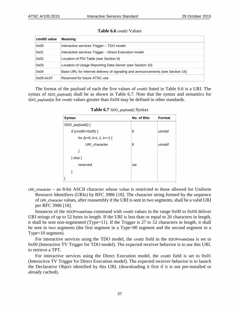
ATSC A/105:2015 Interactive Services Standard 29 October 2015
37
Table 6.6 cmdID Values
cmdID value Meaning
0x00 Interactive services Trigger – TDO model
0x01 Interactive services Trigger – Direct Execution model
0x02 Location of PDI Table (see Section 9)
0x03 Location of Usage Reporting Data Server (see Section 10)
0x04 Base URL for Internet delivery of signaling and announcements (see Section 16)
0x05-0x1F Reserved for future ATSC use
The format of the payload of each the five values of cmdID listed in Table 6.6 is a URI. The syntax of SDO_payload() shall be as shown in Table 6.7. Note that the syntax and semantics for SDO_payload()s for cmdID values greater than 0x04 may be defined in other standards.
Table 6.7 SDO_payload() Syntax
Syntax No. of Bits Format
SDO_payload() { if (cmdID<0x05) { 8 uimsbf
for (k=0; k<L-1; k++) { URI_character 8 uimsbf
}
} else {
reserved var
}
}
URI_character – an 8-bit ASCII character whose value is restricted to those allowed for Uniform Resource Identifiers (URIs) by RFC 3986 [18]. The character string formed by the sequence of URI_character values, after reassembly if the URI is sent in two segments, shall be a valid URI per RFC 3986 [18]. Instances of the SDOPrivateData command with cmdID values in the range 0x00 to 0x04 deliver
URI strings of up to 52 bytes in length. If the URI is less than or equal to 26 characters in length, it shall be sent non-segmented (Type=11). If the Trigger is 27 to 52 characters in length, it shall be sent in two segments (the first segment in a Type=00 segment and the second segment in a Type=10 segment).
For interactive services using the TDO model, the cmdID field in the SDOPrivateData is set to 0x00 (Interactive TV Trigger for TDO model). The expected receiver behavior is to use this URL to retrieve a TPT.
For interactive services using the Direct Execution model, the cmdID field is set to 0x01 (Interactive TV Trigger for Direct Execution model). The expected receiver behavior is to launch the Declarative Object identified by this URL (downloading it first if it is not pre-installed or already cached).

ATSC A/105:2015 Interactive Services Standard 29 October 2015
38
This delivery mechanism is used for all kinds of Triggers, including both Time Base Triggers and Activation Triggers. 6.5.2 Delivery of Triggers and Other URIs via Internet Several different mechanisms are used for delivery of Time Base Triggers, Activation Triggers and other URIs via Internet. 6.5.2.1 Delivery of Time Base Triggers via Internet Internet delivery of Time Base Triggers is only needed in so-called Automatic Content Recognition (ACR) situations, where the receiver has no access to Closed Caption Service #6. In these situations the receiver needs to use ACR in order to recognize video frames and synchronize the time base with them. In ACR situations Time Base Triggers are obtained from watermarks or from ACR servers. See Section 14 of this document for details. 6.5.2.2 Delivery of Activation Triggers via Internet (ACR Scenario) When delivered via Internet, Activation triggers shall be delivered using either or both of the following mechanisms, at the option of the broadcaster:
• Individual Activation Trigger Delivery • Bulk Activation Trigger Delivery
6.5.2.2.1 Individual Activation Trigger Delivery When individual Activation Triggers are delivered via the Internet, they can be delivered using an ACR server, as specified in Section 14.2.3 of this document, or they can be delivered by HTTP short polling, HTTP long polling or HTTP streaming, as specified immediately below.
The format of the Activation Triggers shall be exactly the same as when they are delivered via DTV CC service #6. When Internet delivery of Activation Triggers is available, the URL attribute of the LiveTrigger element in the TPT indicates the Activation Trigger Server which can deliver them. If the pollPeriod attribute of the LiveTrigger element is present in the TPT, this indicates that HTTP short polling is being used, and it indicates the polling period a receiver should use. If the pollPeriod attribute of the LiveTrigger element is not present in the TPT, this indicates that either HTTP long polling or HTTP streaming is being used.
Regardless of which protocol is being used, the receiver is expected to issue an HTTP request to the Activation Trigger Server with the query term:
?mt=<media_time>
where <media_time> is the current Media Time of the viewed content. If short polling is being used, the response from the Activation Trigger Server shall contain all
the Triggers that have been issued within the time interval of length pollPeriod ending at <media_time>. If more than one Activation Trigger is returned, they shall be separated by one or more white space characters. If no Activation Triggers are returned, the response shall be empty.
If HTTP long polling or HTTP streaming is being used, the Activation Trigger Server shall wait to return a response until the Media Time when an Activation Trigger would be delivered in the broadcast stream. At this time it shall return the Activation Trigger.
If HTTP long polling is being used, the Activation Trigger Server shall close the session after returning an Activation Trigger. The receiver is expected to immediately issue another request, with an updated Media Time.
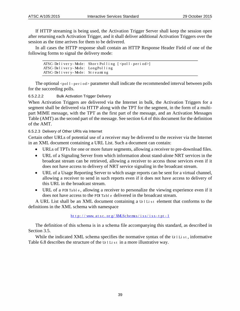
ATSC A/105:2015 Interactive Services Standard 29 October 2015
39
If HTTP streaming is being used, the Activation Trigger Server shall keep the session open after returning each Activation Trigger, and it shall deliver additional Activation Triggers over the session as the time arrives for them to be delivered.
In all cases the HTTP response shall contain an HTTP Response Header Field of one of the following forms to signal the delivery mode:
ATSC-Delivery-Mode: ShortPolling [<poll-period>] ATSC-Delivery-Mode: LongPolling ATSC-Delivery-Mode: Streaming
The optional <poll-period> parameter shall indicate the recommended interval between polls for the succeeding polls. 6.5.2.2.2 Bulk Activation Trigger Delivery When Activation Triggers are delivered via the Internet in bulk, the Activation Triggers for a segment shall be delivered via HTTP along with the TPT for the segment, in the form of a multi-part MIME message, with the TPT as the first part of the message, and an Activation Messages Table (AMT) as the second part of the message. See section 6.4 of this document for the definition of the AMT. 6.5.2.3 Delivery of Other URIs via Internet Certain other URLs of potential use of a receiver may be delivered to the receiver via the Internet in an XML document containing a URL List. Such a document can contain:
• URLs of TPTs for one or more future segments, allowing a receiver to pre-download files. • URL of a Signaling Server from which information about stand-alone NRT services in the
broadcast stream can be retrieved, allowing a receiver to access those services even if it does not have access to delivery of NRT service signaling in the broadcast stream.
• URL of a Usage Reporting Server to which usage reports can be sent for a virtual channel, allowing a receiver to send in such reports even if it does not have access to delivery of this URL in the broadcast stream.
• URL of a PDITable, allowing a receiver to personalize the viewing experience even if it does not have access to the PDITable delivered in the broadcast stream.
A URL List shall be an XML document containing a UrlList element that conforms to the definitions in the XML schema with namespace
http://www.atsc.org/XMLSchemas/iss/iss-tpt-1
The definition of this schema is in a schema file accompanying this standard, as described in Section 3.5.
While the indicated XML schema specifies the normative syntax of the UrlList, informative Table 6.8 describes the structure of the UrlList in a more illustrative way.

ATSC A/105:2015 Interactive Services Standard 29 October 2015
40
Table 6.8 URL List XML Diagram (Informative)
Element/Attribute (with @) Cardinality Data Type Description and Value
UrlList List of potentially useful URLs
TptUrl 0..N anyURI URL of TPT for future segment
NrtSignalingUrl 0..1 anyURI URL of NRT Signaling Server
UrsUrl 0..1 anyURI URL of Usage Reporting Server
PdiUrl 0..1 anyURL URL of PDITable
The semantics of these elements shall be as follows: UrlList – This element contains a list of URLs that are useful to a receiver. TptUrl – This optional element of the UrlList element shall contain the URL of a TPT for a future
segment in the current interactive adjunct service. When multiple TptUrl elements are included, they shall be arranged in order of the appearance of the segments in the broadcast.
NrtSignalingUrl – This optional element of the UrlList element shall contain the URL of a server from which receivers can obtain NRT signaling tables for all the virtual channels in the current transport stream, using the request protocol defined in Section 15 of this standard.
UrsUrl – This optional element of the UrlList element shall contain the URL of a server to which receivers can send service usage reports, using the protocol defined in Section 9 of this standard.
PdiUrl – This optional element of the UrlList element shall contain the URL of a PDITable. When a URL List is delivered via the Internet, it shall be delivered via HTTP along with a
TPT, in the form of a multi-part MIME message as specified in Section 6.5.4 below. 6.5.3 Delivery of TPTs in Broadcast Stream When TPTs are delivered in the broadcast stream, each TPT instance shall be compressed with the GZIP algorithm [6], using the DEFLATE compression algorithm. The FNAME field shall be present in the gzip header. The value of the FNAME field shall be the URL of the TPT instance, without the “http:” term. Each compressed TPT instance shall be encapsulated in NRT-style private sections with structure as defined in Table 6.9 below, by dividing each compressed TPT into blocks with arbitrary byte boundaries and inserting the blocks into the tpt_bytes() fields of private sections that have a common value of table_id, protocol_version TPT_data_version and sequence_number fields in the section headers. The section_number field value of each section shall give the order in which the block it contains appears in the compressed TPT instance. The private sections shall be carried in the Service Signaling Channel (SSC) of the IP subnet of the virtual channel to which the TPT pertains. The definition of the terms “Service Signaling Channel” and “IP subnet” in this standard shall be those defined A/103 [2]. (The sequence_number fields in the sections are used to distinguish different TPT instances carried in the same SSC.
The format for the private sections containing TPTs shall be as defined in Table 6.9 below. The semantics of the fields in Table 6.9 shall conform to the specifications following the table.
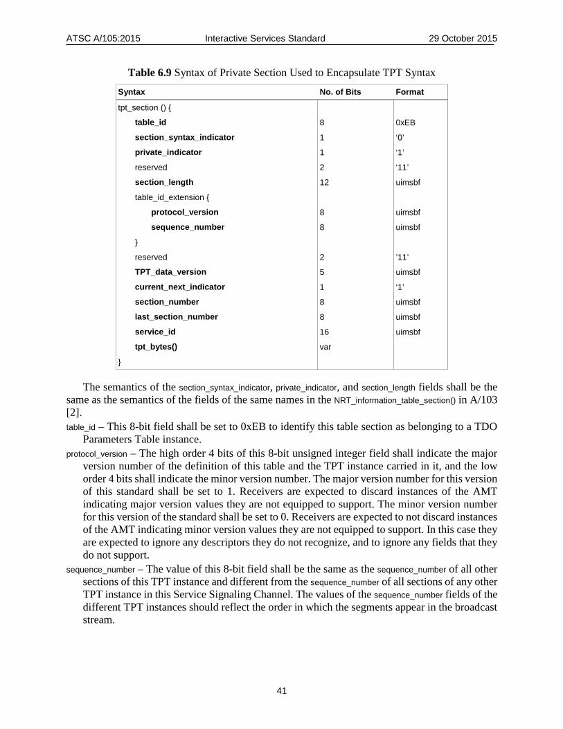
ATSC A/105:2015 Interactive Services Standard 29 October 2015
41
Table 6.9 Syntax of Private Section Used to Encapsulate TPT Syntax
Syntax No. of Bits Format
tpt_section () {
table_id 8 0xEB
section_syntax_indicator 1 ‘0’
private_indicator 1 ‘1’
reserved 2 ‘11’
section_length 12 uimsbf
table_id_extension {
protocol_version 8 uimsbf
sequence_number 8 uimsbf
}
reserved 2 ’11’
TPT_data_version 5 uimsbf
current_next_indicator 1 ‘1’
section_number 8 uimsbf
last_section_number 8 uimsbf
service_id 16 uimsbf
tpt_bytes() var
}
The semantics of the section_syntax_indicator, private_indicator, and section_length fields shall be the same as the semantics of the fields of the same names in the NRT_information_table_section() in A/103 [2]. table_id – This 8-bit field shall be set to 0xEB to identify this table section as belonging to a TDO
Parameters Table instance. protocol_version – The high order 4 bits of this 8-bit unsigned integer field shall indicate the major
version number of the definition of this table and the TPT instance carried in it, and the low order 4 bits shall indicate the minor version number. The major version number for this version of this standard shall be set to 1. Receivers are expected to discard instances of the AMT indicating major version values they are not equipped to support. The minor version number for this version of the standard shall be set to 0. Receivers are expected to not discard instances of the AMT indicating minor version values they are not equipped to support. In this case they are expected to ignore any descriptors they do not recognize, and to ignore any fields that they do not support.
sequence_number – The value of this 8-bit field shall be the same as the sequence_number of all other sections of this TPT instance and different from the sequence_number of all sections of any other TPT instance in this Service Signaling Channel. The values of the sequence_number fields of the different TPT instances should reflect the order in which the segments appear in the broadcast stream.
ATSC A/105:2015 Interactive Services Standard 29 October 2015
42
TPT_data_version – This 5-bit field shall indicate the version number of this TPT instance, where the TPT instance is defined by its segment_id. The version number shall be incremented by 1 modulo 32 when any field in the TPT instance changes.
current_next_indicator – This 1-bit indicator shall always be set to ‘1’ for TPT sections, indicating that the TPT sent is always the current TPT for the segment identified by its segment_id.
section_number – This 8-bit field shall give the section number of this TPT instance section, where the TPT instance is identified by its segment_id. The section_number of the first section in an TPT instance shall be 0x00. The section_number shall be incremented by 1 with each additional section in the TPT instance.
last_section_number – This 8-bit field shall give the number of the last section (i.e., the section with the highest section_number) of the TPT instance of which this section is a part.
service_id – This 16-bit field shall specify the service_id associated with the interactive service offering the content items described in this table instance.
tpt_bytes() – This variable length field shall consist of a block of the TPT instance carried in part by this section. When the tpt_bytes() fields of all the sections of this table instance are concatenated in order of their section_number fields, the result shall be the complete TPT instance.
6.5.4 Delivery of TPTs via Internet When delivered over the Internet, TPTs shall be delivered via HTTP. The URL for the TPT of the current segment shall appear in Triggers, delivered either via DTV Closed Caption service #6 or via an ACR server. The response to a request for a TPT may consist of just the TPT for the current segment, or it may consist of a multipart MIME message, with the requested TPT in the first part, and optionally the AMT for the segment in the second part, and optionally a UrlList XML document in the next part.
7. DO EXECUTION ENVIRONMENT SPECIFICATION
7.1 DAE Specifications Based on OIPF/HbbTV The portions of OIPF DAE [12] that shall be used for the Declarative Object execution environment, as modified by the cited HbbTV standard (TS 102 796 [16]) modifications and certain additional ATSC modifications, are those indicated in Annex A of the present document.
7.2 Trigger Access APIs 7.2.1 Triggered Event Access APIs In order to support synchronization of Declarative Object actions to broadcast programming, the following additional methods shall be supported for the video/broadcast object defined in Section 7.2.4 of OIPF DAE [12].
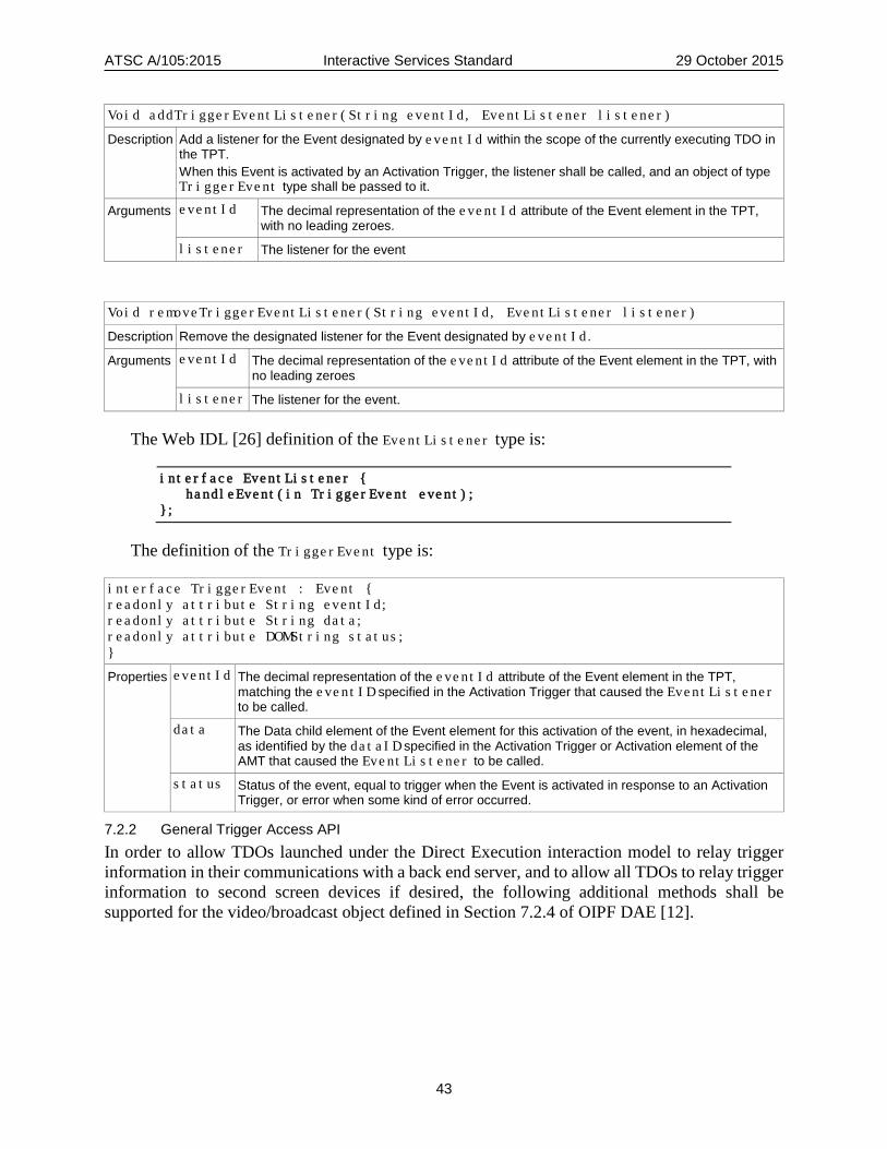
ATSC A/105:2015 Interactive Services Standard 29 October 2015
43
Void addTriggerEventListener(String eventId, EventListener listener)
Description Add a listener for the Event designated by eventId within the scope of the currently executing TDO in the TPT. When this Event is activated by an Activation Trigger, the listener shall be called, and an object of type TriggerEvent type shall be passed to it.
Arguments eventId The decimal representation of the eventId attribute of the Event element in the TPT, with no leading zeroes.
listener The listener for the event
Void removeTriggerEventListener(String eventId, EventListener listener)
Description Remove the designated listener for the Event designated by eventId.
Arguments eventId The decimal representation of the eventId attribute of the Event element in the TPT, with no leading zeroes
listener The listener for the event.
The Web IDL [26] definition of the EventListener type is:
interface EventListener { handleEvent(in TriggerEvent event); };
The definition of the TriggerEvent type is:
interface TriggerEvent : Event { readonly attribute String eventId; readonly attribute String data; readonly attribute DOMString status; }
Properties eventId The decimal representation of the eventId attribute of the Event element in the TPT, matching the eventID specified in the Activation Trigger that caused the EventListener to be called.
data The Data child element of the Event element for this activation of the event, in hexadecimal, as identified by the dataID specified in the Activation Trigger or Activation element of the AMT that caused the EventListener to be called.
status Status of the event, equal to trigger when the Event is activated in response to an Activation Trigger, or error when some kind of error occurred.
7.2.2 General Trigger Access API In order to allow TDOs launched under the Direct Execution interaction model to relay trigger information in their communications with a back end server, and to allow all TDOs to relay trigger information to second screen devices if desired, the following additional methods shall be supported for the video/broadcast object defined in Section 7.2.4 of OIPF DAE [12].

ATSC A/105:2015 Interactive Services Standard 29 October 2015
44
Void addTriggerListener(TriggerListener listener)
Description Add a listener for triggers. When a trigger is delivered to the receiver (in the broadcast stream or from an ACR server), or when a TDO Event activation is due to be generated from an AMT that has been delivered to the receiver, the listener shall be called, and an object of Trigger type representing the trigger shall be passed to the listener.
Argument listener The trigger listener that is to be added
Void removeTriggerListener(TriggerListener listener)
Description Remove the designated listener for triggers.
Argument listener The trigger listener that is to be removed
The Web IDL [26] definition of the TriggerListener type is:
interface TriggerListener { handleTrigger(in Trigger trigger); };
The definition of the Trigger type is:
Interface Trigger: Event { readonly attribute String triggerType; readonly attribute String trigger; readonly attribute DOMString status; }
Properties triggerType Decimal representation of the cmdID of the trigger, as that term is defined in section 6.5.1 of this document.
trigger The text of the trigger that was delivered to the receiver, or in the case of a TDO Event activation generated from an AMT, the representation of the Event activation in the form of an Activation Trigger, as that term is defined in section 6.2.3 of this document.
status Status of the event, equal to trigger when the event is activated in response to a trigger arriving, or error when some kind of error occurred.
7.3 APIs for Second Screen Device Support The following APIs allow a DO executing in a primary device to engage in two-way communications with applications running in second screen devices, using the Two-Way Communications service defined in Section 13.5.3 of this standard.
The TV Receiver should set the UPnP “Status” state variable for the Two-Way Communications service to “false” whenever a DO terminates, so that a new DO must proactively set it to “true” before communicating.
The following new property shall be added to the NetworkInterface class defined in Section 7.3.4 of OIPF DAE [12].

ATSC A/105:2015 Interactive Services Standard 29 October 2015
45
function onBytesReceived (String address, String bytes)
This callback function is called when bytes are received for a DO via the Two-Way Communications service. The two arguments are defined as follows: String address – A string containing the IP address and UDP port of the sender of the received bytes, in the format < address>:< port>. String bytes – The received bytes
The new methods defined below shall be added to the NetworkInterface class defined in Section 7.3.4 of OIPF DAE [12].
void setStatusYes()
Description Sets the value of the UPnP Boolean state variable “Status” of the Two-Way Communications Service to “true”, indicating that the DO is prepared to engage in communications.
Arguments None.
void setStatusNo()
Description Sets the value of the UPnP Boolean state variable “Status” of the Two-Way Communications Service to “false”, indicating that the DO is not prepared to engage in communications.
Arguments None
void sendBytes(String address, String bytes)
Description Send bytes using the Two-Way Communications service.
Arguments address The destination TCP/IP address and port for the bytes, in the format <address>:<port>.
bytes The bytes to be sent
The following API method allows a DO executing in a primary device to publish the name and URL of a companion second screen application.
To support the AppURL service defined in Section 13.5.4 of this standard, a new PublishURL class is added to this specification with the new method defined below.
void setAppURL(String url, String name)
Description Sets the value of the UPnP state variable AppURL of the AppURL Service to the value of the url argument, and sets the UPnP state variable AppName of the AppURL service to the value of the name argument. If there is no associated second screen app known, the values of the URL and name arguments shall be the null string.
Arguments url The base URL of a second screen app associated with the currently executing DO
name The name of a second screen app associated with the currently executing DO
7.4 Link and Packaged App Management APIs An ATSC 2.0 receiver that supports Links and Packaged Apps shall support the new method defined in Table 7.1 below, as a method of the ApplicationManager object defined in OIPF DAE [12].

ATSC A/105:2015 Interactive Services Standard 29 October 2015
46
Table 7.1 Definition of ApplicationManager.addLink() Method Integer addLink(String uri, String linkMetadata)
Description When successful, this method shall cause the receiver to add a Link to its list of Links, as described in Section 12. The integer return value of this method shall indicate whether or not the call was successful, and it shall provide the reason for failure if it failed, according to Table 7.2 below.
Arguments uri The input URI value shall be the URL that is to be saved as a Link.
linkMetadata The input linkMetadata value shall represent the metadata to be associated with the Link, in the form of a UTF-8 representation of an XML document with root element LinkMetadata conforming to the schema described by Table 7.3 below and normatively defined in a schema definition file accompanying this standard with namespace http://www.atsc.org/XMLSchemas/iss/iss-misc-1. In case of any discrepancy between Table 7.3 and the XML schema in the schema file, the schema fill shall take precedence.
Table 7.2 Error Codes Returned by addLink() Method
Code Value Meaning
0 Call succeeded; Link added
1 Call failed; syntax of uri argument invalid
2 Call failed; format of linkMetadata argument invalid
3 Call failed; upper limit on number of stored links exceeded
Table 7.3 Schema Table for LinkMetadata Input Argument
Element/Attribute Cardinality XML data type Description
LinkMetadata 1
@url 1 anyURI URL to be saved as Link
@title 0..1 string Title of Link
@majChanNum 0..1 unsignedShort Major channel # where Link offered
@minChanNum 0..1 unsignedShort Minor channel # where Link offered
@channelName 0..1 string Name of channel where Link offered
@programName 0..1 string Name of program when Link offered
@expiration 0..1 dateTime Expiration date/time of Link
Icon 0..N
@source 1 anyURI Pointer to icon file
@width 0..1 unsignedShort Icon width, in pixels
@height 0..1 unsignedShort Icon height, in pixels
The semantics of the elements and attributes in Table 7.3 are as follows: @url – The @url attribute shall be the URL associated with the Link – i.e., the URL of the object
that the Link points to. @title – When present, the @title attribute shall be the title of the Link, intended for display to
users.
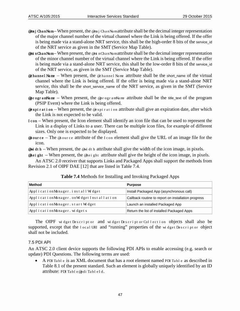
ATSC A/105:2015 Interactive Services Standard 29 October 2015
47
@majChanNum – When present, the @majChanNum attribute shall be the decimal integer representation of the major channel number of the virtual channel where the Link is being offered. If the offer is being made via a stand-alone NRT service, this shall be the high-order 8 bits of the service_id of the NRT service as given in the SMT (Service Map Table).
@minChanNum – When present, the @minChanNum attribute shall be the decimal integer representation of the minor channel number of the virtual channel where the Link is being offered. If the offer is being made via a stand-alone NRT service, this shall be the low-order 8 bits of the service_id of the NRT service, as given in the SMT (Service Map Table).
@channelName – When present, the @channelName attribute shall be the short_name of the virtual channel where the Link is being offered. If the offer is being made via a stand-alone NRT service, this shall be the short_service_name of the NRT service, as given in the SMT (Service Map Table).
@programName – When present, the @programName attribute shall be the title_text of the program (PSIP Event) where the Link is being offered.
@expiration – When present, the @expiration attribute shall give an expiration date, after which the Link is not expected to be valid.
Icon – When present, the Icon element shall identify an icon file that can be used to represent the Link in a display of Links to a user. There can be multiple icon files, for example of different sizes. Only one is expected to be displayed.
@source – The @source attribute of the Icon element shall give the URL of an image file for the icon.
@width – When present, the @width attribute shall give the width of the icon image, in pixels. @height – When present, the @height attribute shall give the height of the icon image, in pixels.
An ATSC 2.0 receiver that supports Links and Packaged Apps shall support the methods from Revision 2.1 of OIPF DAE [12] that are listed in Table 7.4.
Table 7.4 Methods for Installing and Invoking Packaged Apps
Method Purpose
ApplicationManager.installWidget Install Packaged App (asynchronous call)
ApplicationManager.onWidgetInstallation Callback routine to report on installation progress
ApplicationManager.startWidget Launch an installed Packaged App
ApplicationManager.widgets Return the list of installed Packaged Apps
The OIPF widgetDescriptor and widgetDescriptorCollection objects shall also be supported, except that the localURI and “running” properties of the widgetDescriptor object shall not be included.
7.5 PDI API An ATSC 2.0 client device supports the following PDI APIs to enable accessing (e.g. search or update) PDI Questions. The following terms are used:
• A PDITable is an XML document that has a root element named PDITable as described in Table 8.1 of the present standard. Such an element is globally uniquely identified by an ID attribute: PDITable@pdiTableId.
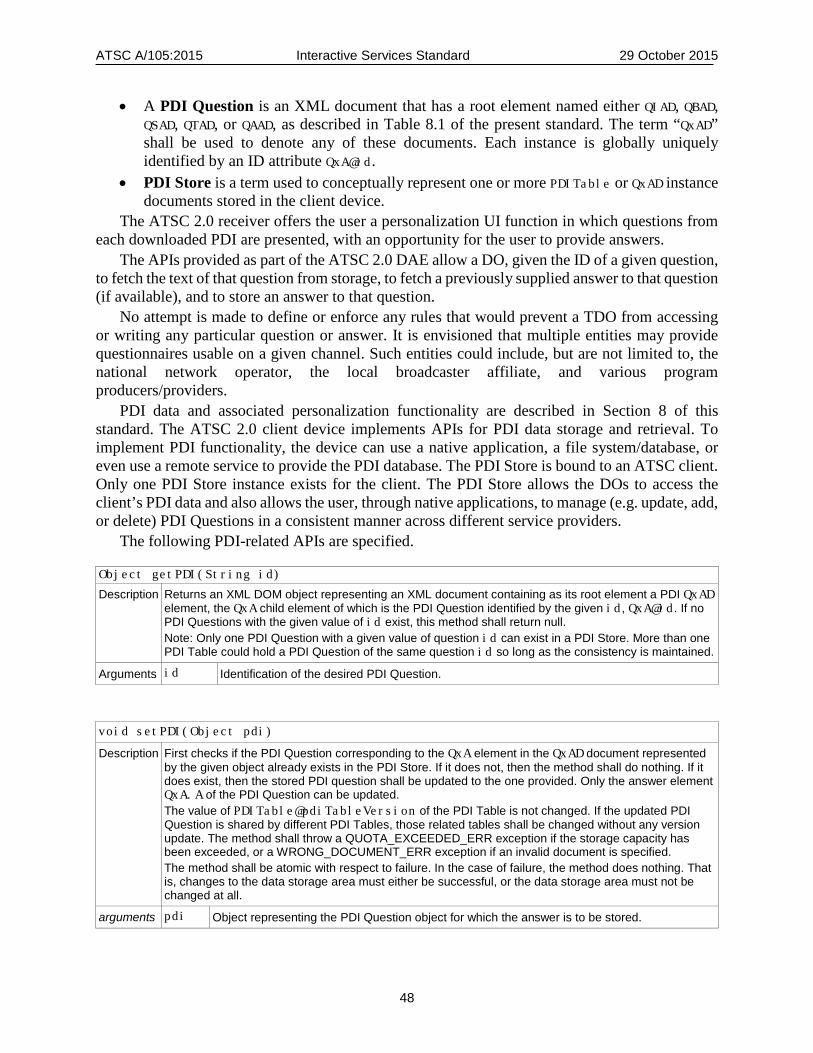
ATSC A/105:2015 Interactive Services Standard 29 October 2015
48
• A PDI Question is an XML document that has a root element named either QIAD, QBAD, QSAD, QTAD, or QAAD, as described in Table 8.1 of the present standard. The term “QxAD” shall be used to denote any of these documents. Each instance is globally uniquely identified by an ID attribute QxA@id.
• PDI Store is a term used to conceptually represent one or more PDITable or QxAD instance documents stored in the client device.
The ATSC 2.0 receiver offers the user a personalization UI function in which questions from each downloaded PDI are presented, with an opportunity for the user to provide answers.
The APIs provided as part of the ATSC 2.0 DAE allow a DO, given the ID of a given question, to fetch the text of that question from storage, to fetch a previously supplied answer to that question (if available), and to store an answer to that question.
No attempt is made to define or enforce any rules that would prevent a TDO from accessing or writing any particular question or answer. It is envisioned that multiple entities may provide questionnaires usable on a given channel. Such entities could include, but are not limited to, the national network operator, the local broadcaster affiliate, and various program producers/providers.
PDI data and associated personalization functionality are described in Section 8 of this standard. The ATSC 2.0 client device implements APIs for PDI data storage and retrieval. To implement PDI functionality, the device can use a native application, a file system/database, or even use a remote service to provide the PDI database. The PDI Store is bound to an ATSC client. Only one PDI Store instance exists for the client. The PDI Store allows the DOs to access the client’s PDI data and also allows the user, through native applications, to manage (e.g. update, add, or delete) PDI Questions in a consistent manner across different service providers.
The following PDI-related APIs are specified.
Object getPDI(String id)
Description Returns an XML DOM object representing an XML document containing as its root element a PDI QxAD element, the QxA child element of which is the PDI Question identified by the given id, QxA@id. If no PDI Questions with the given value of id exist, this method shall return null. Note: Only one PDI Question with a given value of question id can exist in a PDI Store. More than one PDI Table could hold a PDI Question of the same question id so long as the consistency is maintained.
Arguments id Identification of the desired PDI Question.
void setPDI(Object pdi)
Description First checks if the PDI Question corresponding to the QxA element in the QxAD document represented by the given object already exists in the PDI Store. If it does not, then the method shall do nothing. If it does exist, then the stored PDI question shall be updated to the one provided. Only the answer element QxA.A of the PDI Question can be updated. The value of PDITable@pdiTableVersion of the PDI Table is not changed. If the updated PDI Question is shared by different PDI Tables, those related tables shall be changed without any version update. The method shall throw a QUOTA_EXCEEDED_ERR exception if the storage capacity has been exceeded, or a WRONG_DOCUMENT_ERR exception if an invalid document is specified. The method shall be atomic with respect to failure. In the case of failure, the method does nothing. That is, changes to the data storage area must either be successful, or the data storage area must not be changed at all.
arguments pdi Object representing the PDI Question object for which the answer is to be stored.
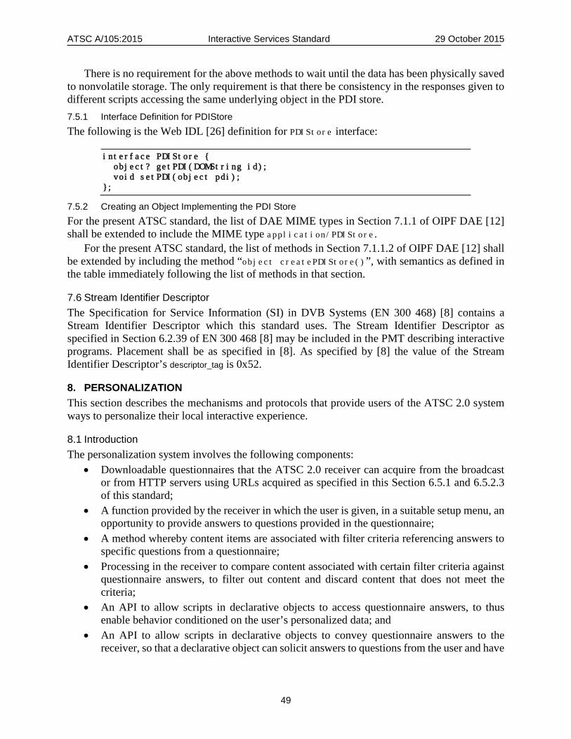
ATSC A/105:2015 Interactive Services Standard 29 October 2015
49
There is no requirement for the above methods to wait until the data has been physically saved to nonvolatile storage. The only requirement is that there be consistency in the responses given to different scripts accessing the same underlying object in the PDI store. 7.5.1 Interface Definition for PDIStore The following is the Web IDL [26] definition for PDIStore interface:
interface PDIStore { object? getPDI(DOMString id); void setPDI(object pdi); };
7.5.2 Creating an Object Implementing the PDI Store For the present ATSC standard, the list of DAE MIME types in Section 7.1.1 of OIPF DAE [12] shall be extended to include the MIME type application/PDIStore.
For the present ATSC standard, the list of methods in Section 7.1.1.2 of OIPF DAE [12] shall be extended by including the method “object createPDIStore()”, with semantics as defined in the table immediately following the list of methods in that section.
7.6 Stream Identifier Descriptor The Specification for Service Information (SI) in DVB Systems (EN 300 468) [8] contains a Stream Identifier Descriptor which this standard uses. The Stream Identifier Descriptor as specified in Section 6.2.39 of EN 300 468 [8] may be included in the PMT describing interactive programs. Placement shall be as specified in [8]. As specified by [8] the value of the Stream Identifier Descriptor’s descriptor_tag is 0x52.
8. PERSONALIZATION This section describes the mechanisms and protocols that provide users of the ATSC 2.0 system ways to personalize their local interactive experience.
8.1 Introduction The personalization system involves the following components:
• Downloadable questionnaires that the ATSC 2.0 receiver can acquire from the broadcast or from HTTP servers using URLs acquired as specified in this Section 6.5.1 and 6.5.2.3 of this standard;
• A function provided by the receiver in which the user is given, in a suitable setup menu, an opportunity to provide answers to questions provided in the questionnaire;
• A method whereby content items are associated with filter criteria referencing answers to specific questions from a questionnaire;
• Processing in the receiver to compare content associated with certain filter criteria against questionnaire answers, to filter out content and discard content that does not meet the criteria;
• An API to allow scripts in declarative objects to access questionnaire answers, to thus enable behavior conditioned on the user’s personalized data; and
• An API to allow scripts in declarative objects to convey questionnaire answers to the receiver, so that a declarative object can solicit answers to questions from the user and have

ATSC A/105:2015 Interactive Services Standard 29 October 2015
50
the answers saved just as if they had been provided using the function provided by the receiver.
The answers to the questionnaires, taken together, represent the user’s Profile, Demographics, and Interests (PDI). The data structure that encapsulates the questionnaire and the answers given by a particular user is called a PDI Questionnaire or a PDI Table. A PDI Table, as provided by a network, broadcaster or content provider, includes no answer data, although the data structure accommodates the answers once they are available. The question portion of an entry in a PDI Table is informally called a “PDI Question” or “PDI-Q.” The answer to a given PDI question is referred to informally as a “PDI-A.” A set of filter criteria is informally called a “PDI-FC.”
Figure 8.1 describes the relationships among personalization features at a high level.
PDI Questionnaire
APIfor PDI Manipulation
PDI Store
PDI-A
PDI-Q
Service Provider
Contents Store
Contents (or DOs) of Interest
FilteringEngine
ContentsContentsContents
Declarative Objects (TDO)
PDI Manipulation(Generate/Update/Delete etc.)
Application
PDI- FC
Matching
PDI-A Generator
Figure 8.1 Personalization flow diagram.
At the top, the network, broadcaster, or content provider originates content items, a PDI Table, and declarative objects such as TDOs. The receiver at the bottom receives and stores the PDI Table and provides a “PDI manipulation” application which presents the user with a user interface allowing him or her to reply to each question in the questionnaire. PDI answers are stored in the receiver.
Declarative objects provided by a service provider can include PDI scripts which, by use of the API provided for PDI manipulation, access PDI-Q and PDI-A data in the receiver. A script in the DO can use the API to retrieve one or more PDI questions from the PDI Store, present them to the user, prompt for the answers, and then use the API to store the replies back into the PDI Store in the receiver.
On the left, various items of content are shown originating from the service provider. A given item of content can have associated with it a set of filter criteria (PDI-FC). The receiver can process the PDI-FC against its PDI-A data to determine which items of content are likely to be of interest to the user, and which are not. In some applications, the PDI-FC will simply help a script perform a personalized selection operation when several items of content are available. As shown, items of content that pass the filter are stored.

ATSC A/105:2015 Interactive Services Standard 29 October 2015
51
Figure 8.2 describes the PDI system in terms of interfaces.
PDI-QGenerator
PDI-AGenerator
Filtering Engine
ContentsDistributor
PDI-QGeneration
Contents MetadataDistributor
PDI-AGeneration Contents metadata
generation including PDI-FC
Contents filtering according to associated
metadata and PDI-A
Client
ReferringContents
PDI-Q
PDI-APDI-FC
Metadata
PDI Store
PDI-Q
PDI-A
PDI-Q DeliveryInterface
PDI-FC DeliveryInterface
Provider Server
Contents
Figure 8.2 PDI interfaces.
A client device such as an ATSC 2.0-capable receiver is shown on the left, and servers operated by a service provider are shown at the right. The client device includes a function allowing the creation of answers to the questions in the questionnaire (PDI-A instances). This PDI-generation function uses PDI-Q instances as input and produces PDI-A instances as output. Both PDI-Q and PDI-A instances are saved in non-volatile storage in the receiver. The client also provides a filtering function in which it compares PDI-A instances against PDI-FC instances to determine which content items will be suitable for downloading and use.
On the service provider side as shown, a function is implemented to maintain and distribute the PDI Table. Along with content, content metadata are created. Among the metadata are PDI-FC instances, which are based on the questions in the PDI Table.
8.2 PDI Table Format and Semantics Table 8.1 below depicts the XML schema definition for a root element called PDITable, which defines the structure of PDITable instance documents. It also depicts the XML schema definitions for root elements QIAD, QBAD, QSAD, QTAD, or QAAD, which represent individual questions that can be passed back and forth between DOs and the underlying receiver, using the APIs defined in Section 7.5 of this standard.
These elements shall conform to the definitions in the XML schema with namespace
http://www.atsc.org/XMLSchemas/iss/iss-pdi-1
This schema is defined in a schema file accompanying this standard, as described in Section 3.5 above.
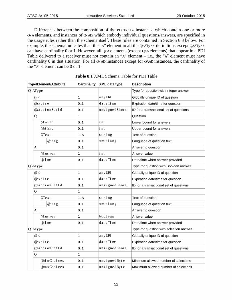
ATSC A/105:2015 Interactive Services Standard 29 October 2015
52
Differences between the composition of the PDITable instances, which contain one or more QxA elements, and instances of QxAD, which embody individual questions/answers, are specified in the usage rules rather than the schema itself. These rules are contained in Section 8.3 below. For example, the schema indicates that the “A” element in all the QxAType definitions except QAAType can have cardinality 0 or 1. However, all QxA elements (except QAA elements) that appear in a PDI Table delivered to a receiver must not contain an “A” element – i.e., the “A” element must have cardinality 0 in that situation. For all QxAD instances except for QAAD instances, the cardinality of the “A” element can be 0 or 1.
Table 8.1 XML Schema Table for PDI Table
Type/Element/Attribute Cardinality XML data type Description
QIAType Type for question with integer answer
@id 1 anyURI Globally unique ID of question
@expire 0..1 dateTime Expiration date/time for question
@xactionSetId 0..1 unsignedShort ID for a transactional set of questions
Q 1 Question
@loEnd 0..1 int Lower bound for answers
@hiEnd 0..1 int Upper bound for answers
QText 1..N string Text of question
@lang 0..1 xml:lang Language of question text
A 0..1 Answer to question
@answer 1 int Answer value
@time 0..1 dateTime Date/time when answer provided
QBAType Type for question with Boolean answer
@id 1 anyURI Globally unique ID of question
@expire 0..1 dateTime Expiration date/time for question
@xactionSetId 0..1 unsignedShort ID for a transactional set of questions
Q 1
QText 1..N string Text of question
@lang 0..1 xml:lang Language of question text
A 0..1 Answer to question
@answer 1 boolean Answer value
@time 0..1 dateTime Date/time when answer provided
QSAType Type for question with selection answer
@id 1 anyURI Globally unique ID of question
@expire 0..1 dateTime Expiration date/time for question
@xactionSetId 0..1 unsignedShort ID for a transactional set of questions
Q 1
@minChoices 0..1 unsignedByte Minimum allowed number of selections
@maxChoices 0..1 unsignedByte Maximum allowed number of selections
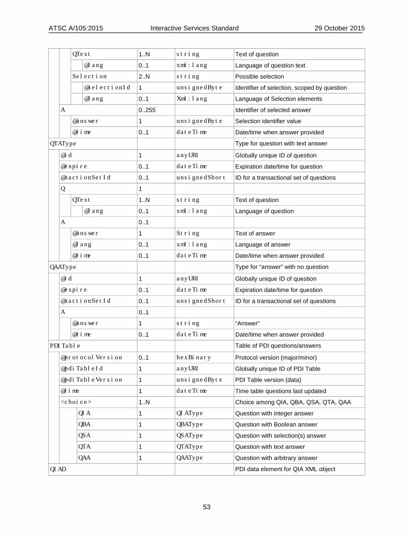
ATSC A/105:2015 Interactive Services Standard 29 October 2015
53
QText 1..N string Text of question
@lang 0..1 xml:lang Language of question text
Selection 2..N string Possible selection
@selectionId 1 unsignedByte Identifier of selection, scoped by question
@lang 0..1 Xml:lang Language of Selection elements
A 0..255 Identifier of selected answer
@answer 1 unsignedByte Selection identifier value
@time 0..1 dateTime Date/time when answer provided
QTAType Type for question with text answer
@id 1 anyURI Globally unique ID of question
@expire 0..1 dateTime Expiration date/time for question
@xactionSetId 0..1 unsignedShort ID for a transactional set of questions
Q 1
QText 1..N string Text of question
@lang 0..1 xml:lang Language of question
A 0..1
@answer 1 String Text of answer
@lang 0..1 xml:lang Language of answer
@time 0..1 dateTime Date/time when answer provided
QAAType Type for “answer” with no question
@id 1 anyURI Globally unique ID of question
@expire 0..1 dateTime Expiration date/time for question
@xactionSetId 0..1 unsignedShort ID for a transactional set of questions
A 0..1
@answer 1 string “Answer”
@time 0..1 dateTime Date/time when answer provided
PDITable Table of PDI questions/answers
@protocolVersion 0..1 hexBinary Protocol version (major/minor)
@pdiTableId 1 anyURI Globally unique ID of PDI Table
@pdiTableVersion 1 unsignedByte PDI Table version (data)
@time 1 dateTime Time table questions last updated
<choice> 1..N Choice among QIA, QBA, QSA, QTA, QAA
QIA 1 QIAType Question with integer answer
QBA 1 QBAType Question with Boolean answer
QSA 1 QSAType Question with selection(s) answer
QTA 1 QTAType Question with text answer
QAA 1 QAAType Question with arbitrary answer
QIAD PDI data element for QIA XML object

ATSC A/105:2015 Interactive Services Standard 29 October 2015
54
@protocolVersion 0..1 hexBinary Protocol version (major/minor)
QIA 1 QIAType Question with integer answer
QBAD PDI data element for QBA XML object
@protocolVersion 0..1 hexBinary Protocol version (major/minor)
QBA 1 QBAType Question with Boolean answer
QSAD PDI data element for QSA XML object
@protocolVersion 0..1 hexBinary Protocol version (major/minor)
QSA 1 QSAType Question with selection(s) answer
QTAD PDI data element for QTA XML object
@protocolVersion 0..1 hexBinary Protocol version (major/minor)
QTA 1 QTAType Question with text answer
QAAD PDI data element for QAA XML object
@protocolVersion 0..1 hexBinary Protocol version (major/minor)
QAA 1 QAAType Answer with no question
The following specifications define the semantics of the attributes and elements in the table. The “id” attributes of the QIAD, QBAD, QSAD, QTAD and QAAD elements (collectively called the
QxAD elements) all have the same semantics, as do the expire attributes of each of these elements. Similarly the lang attributes of each of the QText elements each have the same semantics, as do the time attributes of each of the A elements. Therefore, the semantic definitions of these appear at the end of the list of semantic definitions, rather than appearing multiple times throughout the list. PDITable – This root element contains the list of one or more question elements. Each one is in
the format of QIA, QBA, QSA, QTA, or QAA. The use of the <choice> construct with cardinality 1..N means that any number of QIA, QBA, QSA, QTA and QAA elements can appear in any order.
protocolVersion – This optional attribute of the PDITable root element and QxAD root elements shall consist of two hex digits. The high order four bits shall indicate the major version number of the table definition. The low order four bits shall indicate the minor version number of the table definition. The major version number for this version of this standard shall be set to 1. Receivers are expected to discard instances of the PDI indicating major version values they are not equipped to support. The minor version number for this version of the standard shall be set to 0. Receivers are expected to not discard instances of the PDI indicating minor version values they are not equipped to support. In this case they are expected to ignore any individual elements or attributes they do not support. When protocolVersion is not present, the value “10”, representing major version number 1 and minor version number 0, shall be assumed.
pdiTableId – This required attribute of the PDITable root element shall be a globally unique identifier of this PDITable instance.
pdiTableVersion – This required attribute of the PDITable root element shall indicate the version of this PDITable instance. The initial value shall be 0. The value shall be incremented by 1 each time this PDITable changes, with rollover to 0 after 255.
time – This required attribute of the PDITable root element shall indicate the date and time of the most recent change to any question in this PDI Table.

ATSC A/105:2015 Interactive Services Standard 29 October 2015
55
QIAD – This root element shall contain an integer-answer type of question in the QIA child element. QIA includes optional limits specifying the maximum and minimum allowed values of the answer.
QIA.Q@loEnd – When present, this optional attribute of QIA.Q shall indicate the minimum possible value of the answer attribute in the A child element of this QIA element. I.e., the value of the answer attribute in the A element shall be no less than loEnd. If the loEnd attribute is not present, that shall indicate that there is no minimum.
QIA.Q@hiEnd – When present, this optional attribute of QIA shall indicate the maximum possible value of the answer attribute in the A child element of this QIA element. I.e., the value of the answer attribute in the answer shall be no greater than hiEnd. If the hiEnd attribute is not present, that shall indicate that there is no maximum.
QIA.Q.QText – The value of this child element of QIA.Q shall represent the question string to be presented to users. The question must be formulated to have an integer-type answer.
QIA.A@answer – This integer-valued attribute of QIA.A shall represent an answer to the question in QIA.Q.QText.
QBAD – This root element shall represent a Boolean-answer type of question. QBA.Q.Qtext – The value of this child element of QBA.Q shall represent the question string to be
presented to users. The question must be formulated to have a yes/no or true/false type of answer. There may be multiple instances of this element in different languages.
QBA.A@answer – This Boolean-valued attribute of QBA.A shall represent an answer to the question in QBA.Q.QText.
QSAD – This root element shall represent a selection-answer type of question. QSA.Q@minChoices – When present, this optional attribute of the QSA.Q element shall specify the
minimum number of selections that can be made by a user. If the minChoices attribute is not present, this shall indicate that the minimum number of selections that can be made by a user is 1.
QSA.Q@maxChoices – When present, this optional attribute of the QSA.Q element shall specify the maximum number of selections that can be made by a user. If the maxChoices attribute is not present, this shall indicate that there is no maximum.
QSA.Q.QText – The value of this child element of QSA.Q shall represent the question string to be presented to users. The question must be formulated to have an answer that corresponds to one or more of the provided selection choices. There may be multiple instances of this element in different languages.
QSA.Q.Selection – The value of this child element of QSA.Q shall represent a possible selection to be presented to the user. If there are multiple QSA.Q child elements of the same QSA element (in different languages), each of them shall have the same number of Selection child elements, with the same meanings.
QSA.Q.Selection@selectionId – This required attribute of QSA.Q.Selection shall be an identifier for the QSA.Q.Selection element, unique within the scope of QSA.Q. If there are multiple QSA.Q child elements of the same QSA element (in different languages), there shall be a one-to-one correspondence between the id attributes of their Selection elements, with corresponding Selection elements having the same meaning.
QSA.A – Each instance of QSA shall have zero or more answer elements. QSA.A@answer – This attribute of the QSA.A child element shall specify one allowed answer to this
selection-type question, in the form of the id value of one of the Selection elements.
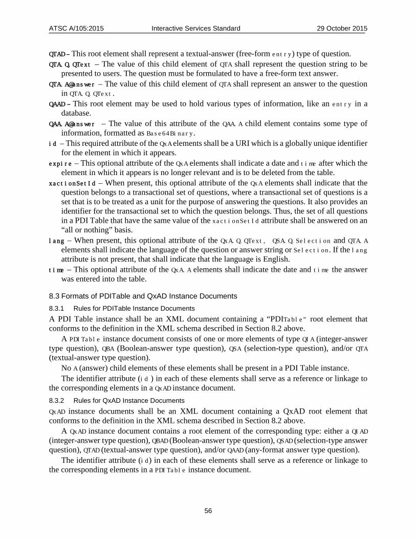
ATSC A/105:2015 Interactive Services Standard 29 October 2015
56
QTAD – This root element shall represent a textual-answer (free-form entry) type of question. QTA.Q.QText – The value of this child element of QTA shall represent the question string to be
presented to users. The question must be formulated to have a free-form text answer. QTA.A@answer – The value of this child element of QTA shall represent an answer to the question
in QTA.Q.QText. QAAD – This root element may be used to hold various types of information, like an entry in a
database. QAA.A@answer – The value of this attribute of the QAA.A child element contains some type of
information, formatted as Base64Binary. id – This required attribute of the QxA elements shall be a URI which is a globally unique identifier
for the element in which it appears. expire – This optional attribute of the QxA elements shall indicate a date and time after which the
element in which it appears is no longer relevant and is to be deleted from the table. xactionSetId – When present, this optional attribute of the QxA elements shall indicate that the
question belongs to a transactional set of questions, where a transactional set of questions is a set that is to be treated as a unit for the purpose of answering the questions. It also provides an identifier for the transactional set to which the question belongs. Thus, the set of all questions in a PDI Table that have the same value of the xactionSetId attribute shall be answered on an “all or nothing” basis.
lang – When present, this optional attribute of the QxA.Q.QText, QSA.Q.Selection and QTA.A elements shall indicate the language of the question or answer string or Selection. If the lang attribute is not present, that shall indicate that the language is English.
time – This optional attribute of the QxA.A elements shall indicate the date and time the answer was entered into the table.
8.3 Formats of PDITable and QxAD Instance Documents 8.3.1 Rules for PDITable Instance Documents A PDI Table instance shall be an XML document containing a “PDITable” root element that conforms to the definition in the XML schema described in Section 8.2 above.
A PDITable instance document consists of one or more elements of type QIA (integer-answer type question), QBA (Boolean-answer type question), QSA (selection-type question), and/or QTA (textual-answer type question).
No A (answer) child elements of these elements shall be present in a PDI Table instance. The identifier attribute (id ) in each of these elements shall serve as a reference or linkage to
the corresponding elements in a QxAD instance document. 8.3.2 Rules for QxAD Instance Documents QxAD instance documents shall be an XML document containing a QxAD root element that conforms to the definition in the XML schema described in Section 8.2 above.
A QxAD instance document contains a root element of the corresponding type: either a QIAD (integer-answer type question), QBAD (Boolean-answer type question), QSAD (selection-type answer question), QTAD (textual-answer type question), and/or QAAD (any-format answer type question).
The identifier attribute (id) in each of these elements shall serve as a reference or linkage to the corresponding elements in a PDITable instance document.
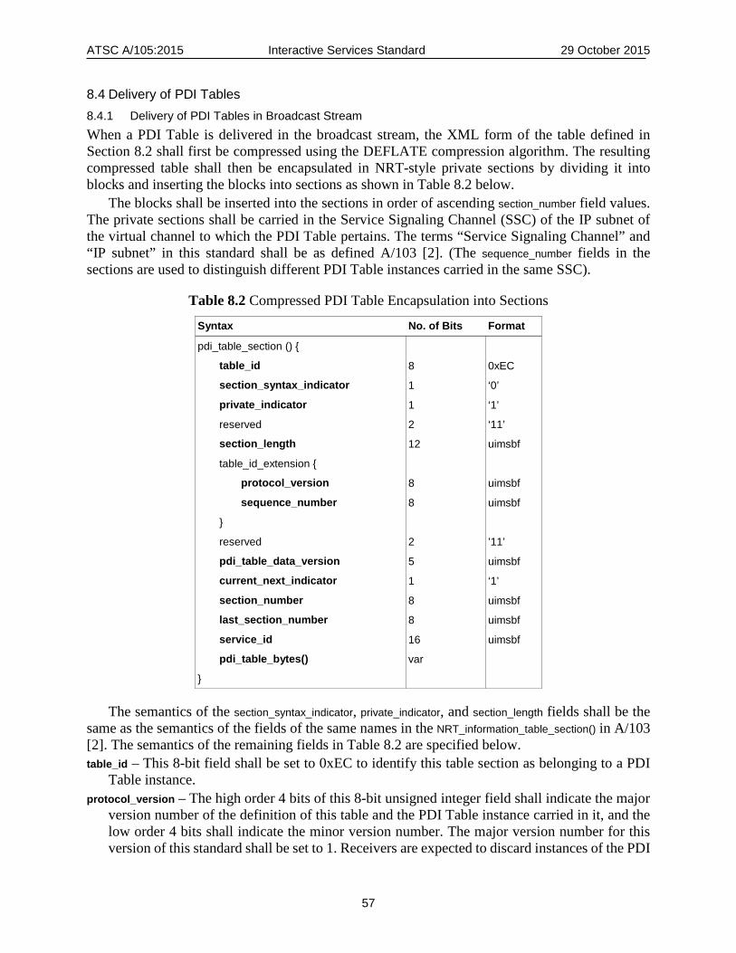
ATSC A/105:2015 Interactive Services Standard 29 October 2015
57
8.4 Delivery of PDI Tables 8.4.1 Delivery of PDI Tables in Broadcast Stream When a PDI Table is delivered in the broadcast stream, the XML form of the table defined in Section 8.2 shall first be compressed using the DEFLATE compression algorithm. The resulting compressed table shall then be encapsulated in NRT-style private sections by dividing it into blocks and inserting the blocks into sections as shown in Table 8.2 below.
The blocks shall be inserted into the sections in order of ascending section_number field values. The private sections shall be carried in the Service Signaling Channel (SSC) of the IP subnet of the virtual channel to which the PDI Table pertains. The terms “Service Signaling Channel” and “IP subnet” in this standard shall be as defined A/103 [2]. (The sequence_number fields in the sections are used to distinguish different PDI Table instances carried in the same SSC).
Table 8.2 Compressed PDI Table Encapsulation into Sections
Syntax No. of Bits Format
pdi_table_section () {
table_id 8 0xEC
section_syntax_indicator 1 ‘0’
private_indicator 1 ‘1’
reserved 2 ‘11’
section_length 12 uimsbf
table_id_extension {
protocol_version 8 uimsbf
sequence_number 8 uimsbf
}
reserved 2 ’11’
pdi_table_data_version 5 uimsbf
current_next_indicator 1 ‘1’
section_number 8 uimsbf
last_section_number 8 uimsbf
service_id 16 uimsbf
pdi_table_bytes() var
}
The semantics of the section_syntax_indicator, private_indicator, and section_length fields shall be the same as the semantics of the fields of the same names in the NRT_information_table_section() in A/103 [2]. The semantics of the remaining fields in Table 8.2 are specified below. table_id – This 8-bit field shall be set to 0xEC to identify this table section as belonging to a PDI
Table instance. protocol_version – The high order 4 bits of this 8-bit unsigned integer field shall indicate the major
version number of the definition of this table and the PDI Table instance carried in it, and the low order 4 bits shall indicate the minor version number. The major version number for this version of this standard shall be set to 1. Receivers are expected to discard instances of the PDI
ATSC A/105:2015 Interactive Services Standard 29 October 2015
58
Table which have major version values they are not equipped to support. The minor version number for this version of the standard shall be set to 0. Receivers are expected to not discard instances of the PDI Table which have minor version values they are not equipped to support. In this case they are expected to ignore any descriptors they do not recognize, and to ignore any fields that they do not support.
sequence_number – The value of this 8-bit field shall be the same as the sequence_number of all other sections of this PDI Table instance and different from the sequence_number of all sections of any other PDI Table instance carried in this Service Signaling Channel. I.e., the sequence_number is used to differentiate sections belonging to different instances of the PDI Table that are delivered in the SSC at the same time.
pdi_table_data_version – This 5-bit field shall indicate the version number of this PDI Table instance, where the PDI Table instance is defined by its pdiTableId value. The version number shall be incremented by 1 modulo 32 when any element or attribute value in the PDI Table instance changes.
current_next_indicator – This 1-bit indicator shall always be set to ‘1’ for PDI Table sections, indicating that the PDI Table sent is always the current PDI Table for the segment identified by its segment_id.
section_number – This 8-bit field shall give the section number of this section of the PDI Table instance. The section_number of the first section in a PDI Table instance shall be 0x00. The section_number shall be incremented by 1 with each additional section in the PDI Table instance.
last_section_number – This 8-bit field shall give the number of the last section (i.e., the section with the highest section_number) of the PDI Table instance of which this section is a part.
service_id – This 16-bit field shall be set to 0x0000 to indicate that this PDI Table instance applies to all data services in the virtual channel in which it appears, rather than to any particular service.
pdi_table_bytes() – This variable length field shall consist of a block of the PDI Table instance carried in part by this section. When the pdi_table_bytes() fields of all the sections of this table instance are concatenated in order of their section_number fields, the result shall be the complete PDI Table instance.
8.4.2 Delivery of PDI Tables Via Internet When delivered over the Internet, PDI Table instances shall be delivered via HTTP or HTTPS. The Content-Type of a PDI Table in the HTTP Response header shall be “text/xml”.
The URL used to retrieve a PDI Table via Internet can be delivered via SDOPrivateData commands as specified in Section 6.5.1 of the present standard, or it can be delivered in a UrlList XML element delivered along with a TPT, as specified in Section 6.5.2.3 of the present standard.
8.5 Filtering Criteria Filtering criteria are associated with downloadable content, so that a TV receiver can decide whether or not to download the content. There are two categories of downloadable content in an ATSC 2.0 environment:
• Non-Real Time (NRT) content in stand-alone NRT services • NRT content items used by TDOs in adjunct interactive data services
This section describes how to associate filtering criteria with downloadable content in both of these situations, and how to interpret the filtering criteria.

ATSC A/105:2015 Interactive Services Standard 29 October 2015
59
8.5.1 Filtering Criteria for NRT Services and Content Items One or more instances of the Filtering Criteria Descriptor defined below can be included in a service level descriptor loop in an NRT Service Map Table (SMT), to allow receivers to determine whether to offer the NRT service to the user or not, or it can be included in a content item level descriptor loop in a Non-Real Time Information Table (NRT-IT), to allow receivers to determine whether to download that particular content item and make it available to the user or not.
The one or more instances of the Filtering Criteria Descriptor allow multiple values to be provided for the same or different targeting criteria. The intended targeting logic is “OR” logic among multiple values for the same targeting criterion, and “AND” logic among different targeting criteria.
The bit stream syntax of the Filtering Criteria Descriptor shall be as described in Table 8.3.
Table 8.3 Filtering Criteria Descriptor Syntax
Syntax No. of Bits Format
filter_criteria_descriptor() {
descriptor_tag 8 0x8E
descriptor_length 8 uimsbf
num_ filter_criteria 8 uimsbf
for (i=0; i<num_filter_criteria; i++) {
criterion_id_length 8 uimsbf
criterion_id var var
criterion_type_code 3 uimsbf
num_criterion_values 5 uimsbf
for (j=0; j<num_criterion_values; j++) {
criterion_value_length 8 uimsbf
criterion_value var
}
}
}
The semantic definitions of the fields in the descriptor are as follows: descriptor_tag – This 8-bit field shall be set to 0x8E to indicate that the descriptor is a Filtering
Criteria Descriptor. descriptor_length – This 8-bit unsigned integer field shall indicate the number of bytes following
the descriptor_length field itself. num_ filter_criteria – This 8-bit field shall indicate the number of filtering criteria contained in this
descriptor. criterion_id_length – This 8-bit field shall indicate the length of the criterion_id field. criterion_id – This variable length field shall give the identifier of this filtering criterion, in the form
of a URI matching the id attribute of a question (QIA, QBA, QSA, QTA, or QAA element) in the PDITable of the virtual channel in which this descriptor appears.

ATSC A/105:2015 Interactive Services Standard 29 October 2015
60
criterion_type_code – This 3-bit field shall give the type of this criterion (question), according to Table 8.4 below.
Table 8.4 Criterion Type Code Values
criterion_type_code Value
0x00 Reserved
0x01 Integer type (including selection id), in uimsbf format
0x02 Boolean type, 0x01 for “true” and 0x00 for “false”
0x03 String type
0x04 – 0x07 Reserved for future ATSC use
num_criterion_values – This 5-bit field gives the number of targeting criterion values in this loop for this filtering criterion, where each value is a possible answer to the question (QIA, QBA, QSA, QTA, or QAA) identified by the criterion_id.
criterion_value_length – This 8-bit field gives the number of bytes needed to represent this targeting criterion value.
criterion_value – This variable length field gives this targeting criterion value. The Filtering Criteria Descriptor indicates values for certain targeting criteria associated with
services or content items. In an ATSC 2.0 emission, one or more instances of the filtering_criteria_descriptor() defined above may go in the descriptor loop of an NRT service in an SMT or in the descriptor loop of a content item in an NRT-IT. In the former case, they shall apply to the service itself (all content items). In the latter case they shall apply to the individual content item.
If there is only one Filtering Criteria Descriptor in a descriptor loop, and if it has only one criterion value, then the decision for whether the service or content item passes the filter shall be “true” (yes) if the criterion value matches a value that is among the answers in the PDI-A for the question corresponding to the filtering criterion (as indicated by the criterion_id), and it shall be “false” (no) otherwise.
If the total number of criterion values in all Filtering Criteria Descriptors in a single descriptor loop is greater than one, the result of each criterion value shall be evaluated as an intermediate term, returning “true” if the criterion value matches a value that is among the answers in the PDI-A for the question corresponding to the filtering criterion (as indicated by the criterion_id) and returning “false” otherwise. Among these intermediate terms, those with the same value of filtering criterion (as determined by the criterion_id) shall be logically ORed to obtain the interim result for each targeting criterion, and these interim results shall be logically ANDed together to determine the final result. If the final result evaluates to “true” for a receiver, it shall imply that the associated NRT service or content item passes the filter and is available to be downloaded to the receiver. 8.5.2 Filtering Criteria for Content Items Used by TDOs in a TPT In order to indicate filtering criteria for a content item associated with a TDO, the XML FilteringCriteria element described in Table 8.5 below may be included as a child element of the ContentItem element in the TPT that represents the content item. The normative definition of the syntax of the FilteringCriteria element is defined in the XML schema with namespace
http://www.atsc.org/XMLSchemas/iss/iss-pdi-1

ATSC A/105:2015 Interactive Services Standard 29 October 2015
61
The definition of this schema is in a schema file accompanying this standard, as described in Section 3.5 above.
Table 8.5 XML Filtering Criteria element
Element/Attribute Cardinality XML data type Description
FilteringCriteria Table of filtering criteria
@protocolVersion 0..1 hexBinary Protocol version (major/minor)
<choice> 1..N Filter criteria including the set of filter criterion
QIACriterion 1 Filter criterion with integer value
@id 1 anyURI Globally unique ID of question for filtering
CriterionValue 1..N int Integer value or lower end of range
@extent 0..1 positiveInt Number of integers in range (if > 1)
QBACriterion 1 Filter criterion with Boolean value
@id 1 anyURI Globally unique ID of question for filtering
CriterionValue 1 boolean Boolean value
QSACriterion 1 Filter criterion with selection value
@id 1 anyURI Globally unique ID of question for filtering
CriterionValue 1..N unsignedByte Identifier of selection
QTACriterion 1 Filter criterion with text value
@id 1 anyURI Globally unique ID of question for filtering
CriterionValue 1..N string Text string
@lang 0..1 xml:lang Language of this criterion element
QAACriterion 1 Filter criterion for answer with no question
@id 1 anyURI Globally unique ID of question for filtering
CriterionValue 1..N string Value
The semantics of the elements and attributes in Table 8.5 are as follows: protocolVersion - This optional attribute of the FilteringCriteria root element shall consist
of two hex digits. The high order four bits shall indicate the major version number of the table definition. The low order four bits shall indicate the minor version number of the table definition. The major version number for this version of this standard shall be set to 1. Receivers are expected to discard instances of the FilteringCriteria indicating major version values they are not equipped to support. The minor version number for this version of the standard shall be set to 0. Receivers are expected to not discard instances of the FilteringCriteria indicating minor version values they are not equipped to support. In this case they are expected to ignore any individual elements or attributes they do not support. When protocolVersion is not present, the value “10”, representing major version number 1 and minor version number 0, shall be assumed.
@id – In each place where an @id attribute appears in the table, it shall be the @id attribute of a question in a PDI Table, thereby identifying the question that corresponds to the filter criterion in which the @id attribute appears.

ATSC A/105:2015 Interactive Services Standard 29 October 2015
62
QIACriterion – A QIACriterion element shall represent a filter criterion corresponding to a question with an integer value.
QIACriterion.CriterionValue – If a CriterionValue child element of a QIACriterion element does not contain an @extent element, it shall represent an integer answer for the question corresponding to the filtering criterion. If a CriterionValue child element of a QIACriterion element contains an @extent attribute, then it shall represent the lower end of a numeric range of answers for the question, and the @extent attribute shall represent the number of integers in the range.
QBACriterion – A QBACriterion element shall represent a filter criterion corresponding to a question with a Boolean value.
QBACriterion.CriterionValue – A CriterionValue child element of a QBACriterion element shall represent a Boolean answer for the question corresponding to the filtering criterion.
QSACriterion – A QSACriterion element shall represent a filter criterion corresponding to a question with selection value(s).
QSACriterion.CriterionValue – A CriterionValue child element of a QSACriterion element shall represent the identifier of a selection answer for the question corresponding to the filtering criterion.
QTACriterion – A QTACriterion element shall represent a filter criterion corresponding to a question with string value.
QTACriterion.CriterionValue – A CriterionValue child element of a QTACriterion element shall represent a text answer for the question corresponding to the filtering criterion.
QAACriterion – A QAACriterion element shall represent a filter criterion corresponding to a “question” that has only a text “answer” with no question.
QAACriterion.CriterionValue – A CriterionValue child element of a QAACriterion element shall represent a text “answer” for the “question” corresponding to the filtering criterion. If there is only one CriterionValue element in the FilteringCriteria element, then the
filtering decision for whether the service or content item passes the filter shall be “true” (yes) if the value of the CriterionValue element matches a value that is among the answers in the PDI-A for the question corresponding to the element containing the CriterionValue element (where the question is indicated by the id attribute of the element containing the CriterionValue element), and it shall be “false” (no) otherwise.
In the case of a CriterionValue child element of a QIACriterion element in which the “extent” attribute is present, the value of the CriterionValue element shall be considered to match a value that is among the answers in the corresponding PDI-A if the value of the answer is in the interval defined by the CriterionValue and the extent attribute.
If the total number of CriterionValue elements in the FilteringCriteria element is greater than one, the result of each CriterionValue element shall be evaluated as an intermediate term, returning “true” if the CriterionValue matches a value that is among the answers in the PDI-A for the question corresponding to the filtering criterion (as indicated by the id value) and returning “false” otherwise. Among these intermediate terms, those with the same value of their parent element identifier (QIA.id, QBA.id, etc.) shall be logically ORed to obtain the interim result for each targeting criterion, and these interim results shall be logically ANDed together to determine the final result. If the final result evaluates to “true” for a receiver, it shall imply that the associated content item passes the filter.

ATSC A/105:2015 Interactive Services Standard 29 October 2015
63
8.6 Access to PDI Documents by Applications APIs for applications (DOs) to use for acquiring and saving PDI documents are defined in Section 7.5 of this document.
8.7 Registration of PDI Questions 8.7.1 Registration Process In order to support reuse of questions by different broadcasters, so that consumers are not prompted to answer essentially the same question over and over again, questions should be registered with a registrar to be designated by the ATSC. See Annex E for a description of the contents of a registration record. Pre-Registered Questions
A receiver targeting mechanism is specified in A/103 [2]. The following PDI questions are translations of the receiver targeting criteria defined there. The questions in Table 8.6 shall be considered as pre-registered.
Table 8.6 Pre-Registered Questions
1)
Question ID: atsc.org/PDIQ/gender Question type: QSA Question text: “What is your gender?” Selections (with selection ID values): Male (1) Female (2) Registration date: [Publication Date] Organization: ATSC Contact information: [ATSC's Contact]
2) Question ID: atsc.org/PDIQ/age-bracket Question type: QSA Question text: “What age bracket are you in?” Selections: Ages 2–5 (1) Ages 6–11 (2) Ages 12–17 (3) Ages 18–34 (4) Ages 35–49 (5) Ages 50–54 (6) Ages 55–64 (7) Ages 65+ (8) Registration date: [Publication Date] Organization: ATSC Contact information: [ATSC's Contact]
3) Question ID: atsc.org/PDIQ/working Question type: QSA Question text: “Are you working at a paying job?”
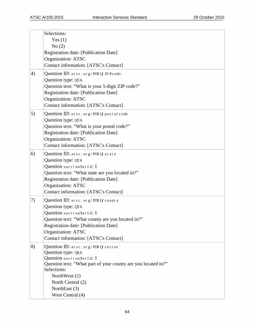
ATSC A/105:2015 Interactive Services Standard 29 October 2015
64
Selections: Yes (1) No (2) Registration date: [Publication Date] Organization: ATSC Contact information: [ATSC's Contact]
4) Question ID: atsc.org/PDIQ/ZIPcode Question type: QTA Question text: “What is your 5-digit ZIP code?” Registration date: [Publication Date] Organization: ATSC Contact information: [ATSC's Contact]
5) Question ID: atsc.org/PDIQ/postalcode Question type: QTA Question text: “What is your postal code?” Registration date: [Publication Date] Organization: ATSC Contact information: [ATSC's Contact]
6) Question ID: atsc.org/PDIQ/state Question type: QTA Question xactionSetId: 1 Question text: “What state are you located in?” Registration date: [Publication Date] Organization: ATSC Contact information: [ATSC's Contact]
7) Question ID: atsc.org/PDIQ/county Question type: QTA Question xactionSetId: 1 Question text: “What county are you located in?” Registration date: [Publication Date] Organization: ATSC Contact information: [ATSC's Contact]
8) Question ID: atsc.org/PDIQ/sector Question type: QSA Question xactionSetId: 1 Question text: “What part of your county are you located in?” Selections: NorthWest (1) North Central (2) NorthEast (3) West Central (4)

ATSC A/105:2015 Interactive Services Standard 29 October 2015
65
Center (5) East Central (6) SouthWest (7) South Central (8) SouthEast (9) Registration date: [Publication Date] Organization: ATSC Contact information: [ATSC's Contact]
9. SERVICE USAGE REPORTING CAPABILITY This section specifies the normative definition of a “Usage Reporting-Capable Receiver,” or URCR. While service usage reporting is generally considered to be an optional feature, it should be noted that broadcasters may make access to certain ATSC 2.0 content contingent upon its support.
9.1 System Overview A service usage data gathering system broadly consists of two main functions:
1) A service usage data client in each device. The client manages the functions of service consumption data collection, storage and transmission to the servers over the device interaction channel.
2) Service usage data server systems operated by (or on behalf of) service providers, either individually or in groups. These servers include data gathering agents; program, break and spot information; and usage report generators.
This URCR specification defines requirements allowing receivers to interoperate with the service usage data server systems operated by (or on behalf of) service providers.
9.2 Specification This section provides the normative specification of URCR receiver functionality. 9.2.1 Consumption Data Unit (CDU) The fundamental record that captures consumption information is called a Consumption Data Unit (CDU). For a streaming A/V channel, each CDU identifies an interval during which the channel was viewed. Such a CDU includes the channel identifier, the time the viewing started and the time the viewing ended. If any TDOs are active during the viewing interval, it also records the intervals during which the TDOs are active (whether on a primary device or a “second screen” device), including the TDO identifier, the time the TDO started being active, and the time it stopped being active.
For a stand-alone NRT service, each CDU captures an interval during which the service was selected. Such a CDU includes the service identifier, the time the interval started, the time the interval ended, and the identifiers of the NRT content items presented during the interval.
For streaming services and stand-alone NRT services, events logged into a CDU shall correspond to usage intervals of no less than 10 seconds. For TDO activity, events logged into a CDU shall correspond to usage intervals of no less than 5 seconds. Thus, if an A/V channel or NRT service remains selected for less than 10 seconds, that event is not reported, and if a TDO is
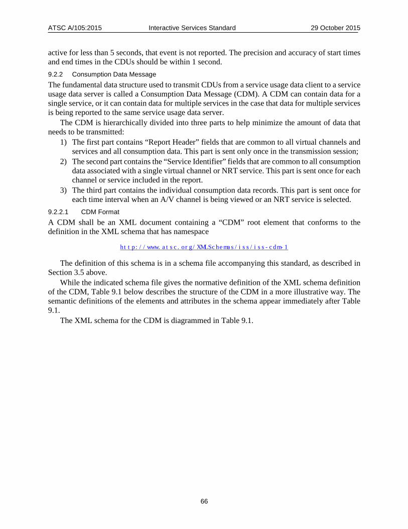
ATSC A/105:2015 Interactive Services Standard 29 October 2015
66
active for less than 5 seconds, that event is not reported. The precision and accuracy of start times and end times in the CDUs should be within 1 second. 9.2.2 Consumption Data Message The fundamental data structure used to transmit CDUs from a service usage data client to a service usage data server is called a Consumption Data Message (CDM). A CDM can contain data for a single service, or it can contain data for multiple services in the case that data for multiple services is being reported to the same service usage data server.
The CDM is hierarchically divided into three parts to help minimize the amount of data that needs to be transmitted:
1) The first part contains “Report Header” fields that are common to all virtual channels and services and all consumption data. This part is sent only once in the transmission session;
2) The second part contains the “Service Identifier” fields that are common to all consumption data associated with a single virtual channel or NRT service. This part is sent once for each channel or service included in the report.
3) The third part contains the individual consumption data records. This part is sent once for each time interval when an A/V channel is being viewed or an NRT service is selected.
9.2.2.1 CDM Format A CDM shall be an XML document containing a “CDM” root element that conforms to the definition in the XML schema that has namespace
http://www.atsc.org/XMLSchemas/iss/iss-cdm-1
The definition of this schema is in a schema file accompanying this standard, as described in Section 3.5 above.
While the indicated schema file gives the normative definition of the XML schema definition of the CDM, Table 9.1 below describes the structure of the CDM in a more illustrative way. The semantic definitions of the elements and attributes in the schema appear immediately after Table 9.1.
The XML schema for the CDM is diagrammed in Table 9.1.

ATSC A/105:2015 Interactive Services Standard 29 October 2015
67
Table 9.1 CDM Logical Structure
Element (or Attribute with @) Cardinality Data Type Description
CDM 1 Consumption Data Message
@protocolVersion 1 hexBinary Major Version of CDM protocol
AVChannel 0..N
@channelNum 1 hexBinary Virtual Channel number
@serviceType 1 unsignedByte e.g., Television, Audio only.
Parameterized
ViewInterval 1..N Virtual channel viewing interval
@startTime 1 dateTime Start time of interval
@endTime 1 dateTime End time of interval
@usageType 1 int Full screen, PIP, etc.
@timeShift 1 boolean @viewStartTime 0..1 dateTime @viewEndTime 0..1 dateTime DOInterval 0..N Interval of active TDO
@doId 1 string DO ID
@startTime 1 dateTime Start time of interval
@endTime 1 dateTime End time of interval
NRTService 0..N NRT service selection interval
@serviceID 1 hexBinary NRTInterval 1..N
@startTime 1 dateTime Start time of interval
@endTime 1 dateTime End time of interval
NRTItem 0..N Content item usage interval
@contentItemId 1 string Content item content linkage
@startTime 1 dateTime Start time of interval
@endTime 1 dateTime End time of interval
protocolVersion – this field shall contain the major and minor protocol versions of the syntax and semantics of the CDM, coded as hexadecimal values each in the range 0x0 to 0xF. The major protocol value shall be in the four most significant bits of the field. A change in the major version level shall indicate a non-backward-compatible level of change. The initial value of this field shall be 0. The value of this field shall be incremented by one each time the structure of the CDM is changed in a non-backward compatible manner from a previous major version. The second number is the file minor version, which shall represent the minor version of the syntax and semantics of the CDM. A change in the minor version level for each value of the first number shall indicate a backward-compatible level of change within that major version. The initial value is 0. The value of this field shall be incremented by one each time the structure of the CMD is changed in backward-compatible manner from a previous minor change (within the scope of a major revision).

ATSC A/105:2015 Interactive Services Standard 29 October 2015
68
AVChannel – This element contains the list of zero or more elements describing activity intervals based on content delivered continuously.
channelNum – this 16-bit hexBinary field shall contain major and minor channel numbers per A/65 [9]. If these numbers are not determinable1, the value shall be set to 0xFFFF.
serviceType – the value of the field service_type that is (or was - for time shifted content) present in the Virtual Channel Table of [9] for the instance being reported.
ViewInterval – one or more periods of display of content for this channelNum. startTime – the dateTime computed from the UTC [9] seconds count at the beginning of the event.
Intervals shall begin when display of the content begins. endTime – the dateTime computed from the UTC [9] seconds count at the end of the event.
Intervals shall end when display of the content ends. usageType – an unsigned integer denoting the class of usage. Defined values are:
1 – Full: content on main screen (no picture in picture). 2 – PIP active: content on main screen with picture in picture activated, no change in main
frame size. 3 – PIP use: content on the ‘small’ picture in picture. 4 – Other/Obscured: user caused content under the control of this standard’s provisions to be
rendered in less than the full frame of the device (such as activating a web session). This includes the potential of user controlling the frame size (such as squeeze with side or top bars).
5 to 99 – Reserved.
Note: This does not reflect any DO presence or absence, as presence and duration of each DO is reported explicitly within each ViewInterval.
timeShift – an unsigned integer 0 or 1, with 1 indicating that the content has been time shifted. viewStartTime – the dateTime computed from the UTC [9] seconds count at the beginning of the
event. Intervals shall end when display of the content begins. viewEndTime – the dateTime computed from the UTC [9] seconds count at the end of the event.
Intervals shall end when display of the content ends. DOInterval – the interval for each active Declarative Object. doId – a string representing an identifier for the declarative object for this reporting record. This
shall contain the c= term of contentID in Section 6.2.3. startTime – the dateTime computed from the UTC [9] seconds count at the beginning of the event.
Intervals shall begin when display of the content begins. The value shall not be less than the value of startTime of this ViewInterval instance.
endTime – the dateTime computed from the UTC [9] seconds count at the end of the event. Intervals shall end when display of the content ends. The value shall not be greater than the value of endTime of this ViewInterval instance.
NRTService - This element contains the list of zero or more elements describing rendering of previously obtained files.
1 The methods are not established and might be proprietary, such as use of an automatic content
recognition system when VCTs are not present.
ATSC A/105:2015 Interactive Services Standard 29 October 2015
69
serviceID - this 16-bit hexBinary field shall contain the service_id as defined by A/103 [2] for files obtained per A/103 [2], or 0xFFFF for rendering periods for any other files from any other source.
NRTInterval – one or more periods of display of a NRT service. startTime – the dateTime computed from the UTC [9] seconds count at the beginning of the event.
Intervals shall begin when display of the content begins. endTime – the dateTime computed from the UTC [9] seconds count at the end of the event.
Intervals shall end when display of the content ends. NRTItem – the interval for each item in the NRT [2] service being rendered. contentItemId – a string which shall contain the contents of the content_name_text() representing
the identifier for the item. startTime – the dateTime computed from the UTC [9] seconds count at the beginning of the event.
Intervals shall begin when display of the content begins. The value shall not be less than the value of startTime of this ViewInterval instance.
endTime – the dateTime computed from the UTC [9] seconds count at the end of the event. Intervals shall end when display of the content ends. The value shall not be greater than the value of endTime of this ViewInterval instance.
9.2.3 Transmission of CDMs
9.2.3.1 URLs for Service Usage Data Servers When a broadcaster wants to receive Service Usage Data Gathering reports, the URL to be used for transmitting CDMs shall be provided by the broadcaster via SDOPrivateData commands per Annex D. The cmdID value is 0x03. The URL for Service Usage Data Gathering Reports may also be delivered in a URL List (Section 6.5.2.3). See Section 6.5.1 of the present standard for the specification of the cmdID field.
The broadcaster decides the granularity of the destination addresses, that is, one destination address URL per service, one per a set of services, one for an RF multiplex, one for a region, one for the nation. This is not explicitly signaled; rather the same URL shall be repeated for each service when the scope is broader than a single service. 9.2.3.2 CDM Transmission Protocol When the URCR is prepared to transmit a CDM to a service usage data server, it shall issue an HTTP PUT request to the server, with the CDM in the body of the request. 9.2.3.3 CDM Transmission Frequency The URCR shall maintain a “date of last” time record which is accessible by TDOs for that service. If a week elapses after the last report, the URCR shall transmit the CDM for that interval with the CDUs for each covered service, or when the allocated CDU storage reaches a level of 80% full, whichever occurs first. 9.2.3.4 Criteria for Retransmission of CDUs Due to Failure Modes If a CDM is not successfully transmitted due to a failure mode, it should remain stored, and it should be retransmitted as soon as the failure mode is rectified.
The following are some of the possible failure modes: • CDM destination address unavailable • Incorrect CDM destination address • HTTP session failure
ATSC A/105:2015 Interactive Services Standard 29 October 2015
70
9.2.4 Opt-In and Opt-Out The URCR should default to the opt-in state for usage data reporting. The URCR shall disclose to the consumer that generic usage data will be reported unless they opt out on a service provider by service provider basis. The method of disclosure of that state to the user is totally optional and need not involve the on screen user interface. The URCR shall report usage data for a given service provider unless the user has opted out of the usage reporting functions for that service provider.
URCRs should have some mechanism for consumers to see what services they have opted into, and to change the state of any opt-in/ opt-out status.
The URCR shall retain opt-in/opt-out choices through loss of power to the unit. For encrypted services, the user interface offering the opt-in/opt-out choice is expected to be
presented during the service authorization process. For unencrypted services, an authorization session may be necessary with TDO-controlled
questions and answers. The URCR shall not directly report any such answers (this is the responsibility of the TDO).
10. PARENTAL CONTROLS The content advisory (rating) for all content delivered during a PSIP Event shall be determined by the content_advisory_descriptor() or its absence as defined by A/65 [9]. Therefore, if the audio/video of an event is blocked because of parental control settings, all adjunct data services associated with the event shall be blocked also.
The content advisory (rating) for all NRT content shall be determined by the content_advisory_descriptor() or its absence as defined by A/103 [2].
11. BROADCASTER NOTIFICATIONS
11.1 Introduction The specifications in this section for ATSC 2.0 Broadcaster Notifications support the ability for a broadcaster to send notifications via the Internet to TV receivers, which will be presented on arrival regardless of which channel is currently selected for viewing on the TV receivers. The typical purpose of such a notification is to deliver some news, or to remind the user to take some action, or in some cases to provide a convenient way for a user to take some action, such as change the channel, by just agreeing to it.
A typical broadcaster notifications scenario is as follows. A TDO or NDO will offer the user an opportunity to subscribe to a notification service,
displaying the name of the notification service (e.g., “WOMH Breaking News”), and whatever else might be useful to help the user decide whether or not to subscribe. If the user accepts, the TDO or NDO will invoke an API to set up the subscription, providing suitable parameters of the service (so that the receiver will know how to retrieve the notifications from the broadcaster’s Internet server). The receiver will ask the user to confirm the subscription, and it will then add the notification service to the receiver’s list of subscribed notification services.
Whenever the receiver is turned on, it will use a polling protocol to acquire notifications continuously from the servers for all the notification services in the receiver’s list of subscribed notification services.
When a notification is acquired, the receiver will display an indication to the user that a notification is available, including the notification service name and notification ID. If the user indicates a desire to accept the notification, the receiver will present the notification.
ATSC A/105:2015 Interactive Services Standard 29 October 2015
71
The receiver will provide a mechanism for users to view the list of subscribed notification streams and delete any that are no longer wanted.
Notifications can only be sent to TV receivers that are turned on, but notifications can be saved and delivered later, if the TV set gets turned on while the notification is still relevant.
11.2 Specifications A receiver supporting the ATSC 2.0 Broadcaster Notifications feature shall support the Remote UI Client role for polling-based 3rd party notifications from an Internet server, as specified in Section 5.6.2 of CEA-2014-A [15], with the restriction that the value for the type argument of the subscribeToNotifications method shall be “general”. Any call to this method with any value other than “general” for the type argument may be treated as an invalid subscription request.
A broadcast server delivering ATSC 2.0 Broadcaster Notifications shall support the Remote UI Server role of that specification.
A receiver supporting the ATSC 2.0 Broadcaster Notifications feature should support the extensions to Section 5.6.2 of CEA-2014 specified in Annex B of the OIPF DAE specification [12], with the value “general” for the type argument of the subscribeToNotificationsAsync method. Any call to this method with any value other than “general” for the type argument may be treated as an invalid subscription request.
When a notification response is received from a server, the receiver should display the notification service name (as provided in the subscribe step) and the notification ID (delivered in the server notification response), and ask the user whether or not to display the notification. If the user agrees, then the notification shall be displayed. Any currently executing Declarative Object may be suspended during the time the notification is displayed.
This requirement for user permission to display a notification does not preclude an option that allows a user to always accept notification displays from a given notification service.
12. LINKS AND PACKAGED APPLICATIONS A “Link” is a broadcaster-provided URL that points to a web site which provides on-line information or functionality related to the current TV programming or NRT service.
A “Packaged App” is a broadcaster-provided Declarative Object (DO) that provides information or functionality which the broadcaster wants to offer viewers, and that is packaged up into a single file for viewers to download and install.
This section provides a mechanism for saving Links and Packaged Apps on a TV receiver, along with associated metadata. In the case of Links, this allows users to access the information or functionality pointed to by the Link at any later time, without missing any of the current program. In the case of Packaged Apps, this allows users to access the information or functionality at any time, without needed to download the DO each time.
12.1 Typical Scenarios A typical scenario for a Link is that a trigger will arrive which causes a TDO to put up an on-screen message that some information or functionality related to the current program is available from a web site, and to offer the user the opportunity to “bookmark” the source for later access.
If the user chooses to “bookmark” the source, the TDO will invoke an API to save the URL of the source, along with appropriate metadata, in the receiver’s set of Links. The receiver will ask the user to confirm that the user wants to add the Link. After it gets the confirmation, it will add the Link to its set of Links. The metadata associated with a Link includes:

ATSC A/105:2015 Interactive Services Standard 29 October 2015
72
• Link URL • Link Title • Date and time the Link was saved • Link Thumbnail/Icon (optional) • Name and number of TV channel that offered the Link (optional) • Name of TV program that offered the Link (optional) • Expiration date and time of the Link (optional) A typical scenario for a Packaged App is that a trigger will arrive that causes a TDO to put up
an on-screen message offering the user a downloadable application that provides some kind of information or functionality.
If the user chooses to accept the offer, the TDO will invoke an API to download the Packaged App and add it to its set of Packaged Apps. The receiver will ask the user to confirm that the user wants to add the Packaged App. After it gets the confirmation, it will download the Packaged App and add it to its set of Packaged Apps.
The Packaged App could be available via Internet, and/or it could be available via a broadcast FLUTE session, at the discretion of the broadcaster.
The user will be able to view the set of Links and/or Packaged Apps on the TV receiver at any time, using a user interface provided by the native TV receiver code, and select one to invoke. The sets of Links and Packaged Apps could be viewed in a list format, much like the display many browsers provide for selecting bookmarks or favorites, or they could be viewed as an icon array format, much like the display of apps on a smartphone, or they could viewed by any other viewing mechanism the designer of the receiver chooses to offer.
The receiver will also provide a mechanism for users to delete any Links or Packaged Apps that are no longer wanted.
The receiver will remove Links from the set of Links when the current date is past their expiration date.
12.2 Specifications The metadata associated with a Link shall include:
• URL • Title • Date and time the Link was saved The metadata associated with a Link may also include: • One or more icon(s) • Number of TV channel in which the Link was offered • Name of TV channel in which the Link was offered • Name of TV program (PSIP event) being viewed when the Link was offered • Expiration date of Link The target of the Link URL shall be a Declarative Object which is compatible with the DAE
specifications contained in the present standard. A Packaged App shall be a Declarative Object which is compatible with the DAE
specifications contained in the present standard, and which is packaged according to the W3C “Widget Packaging and XML Configuration” Recommendation [20].

ATSC A/105:2015 Interactive Services Standard 29 October 2015
73
The DAE APIs to be used for adding Links or Apps shall be as defined in Section 7.4.
13. SECOND SCREEN SUPPORT This section specifies services that can be provided by an ATSC 2.0 Receiver to support the display of content related to an A/V broadcast by applications running on second screen devices (smart phones, tablets, laptops, etc.), including content synchronized with the programming in the broadcast. This specification of services is based on the UPnP Device Architecture. This Architecture is defined in ISO/IEC 29341-1 [11].
13.1 Introduction to UPnP Device Architecture The UPnP Device Architecture defines protocols for communication in an IP network between “controlled devices” that provide services and “control points” that utilize those services. In the ATSC 2.0 “second screen” scenario, an ATSC 2.0 TV receiver plays the role of a “controlled device,” and a second screen device plays the role of a “control point.” (This terminology is perhaps somewhat misleading in the ATSC 2.0 “second screen” scenario, since a second screen device is typically using the services to receive information from an ATSC 2.0 TV receiver, not control it.)
The UPnP Device Architecture specifies: 1) “discovery” protocols for control points to discover controlled devices of interest, 2) “description” protocols for control points to learn details about controlled devices and
services, 3) “control” protocols for control points to invoke “actions” (methods) on controlled devices,
and 4) “eventing” protocols for controlled devices to deliver asynchronous notifications to control
points. (The actions and events are provided by the device services.) When a UPnP controlled device joins a network, it multicasts discovery messages to a “well-
known” IP multicast address and port (registered with IANA). These messages identify the device type and the service types offered by the device, and they give URLs where descriptions of the device and services can be obtained.
When a UPnP control point joins a network, it multicasts a search message asking controlled devices to announce themselves. The search message can specify the device types and/or service types of interest. Relevant devices will respond by sending unicast discovery messages to the control point.
Once a control point gets discovery messages about devices and services of interest, it uses the URLs in the messages to request descriptions of the devices and services. These descriptions include the URLs that can be used to invoke actions and subscribe to events for the services.
13.2 Typical Second Screen Discovery Scenarios Scenario A: The user has an ATSC 2.0 second screen app running in his/her second screen device when the ATSC 2.0 TV receiver joins the network (which perhaps happens when the TV receiver is turned on, or perhaps when its network interface is enabled):
1) An ATSC 2.0 TV receiver that provides second screen support joins the network. 2) The ATSC 2.0 TV receiver multicasts its discovery messages that advertise its ATSC 2.0
second screen support services.
ATSC A/105:2015 Interactive Services Standard 29 October 2015
74
3) The ATSC 2.0 second screen app running in the second screen device receives the multicast discovery messages and sends the ATSC 2.0 TV receiver a request for descriptions of its services.
4) The ATSC 2.0 TV receiver responds with descriptions of its services. 5) The ATSC 2.0 second screen app uses the information given in the descriptions to access
the appropriate services and provide an interactive experience synchronized with the TV programming.
Scenario B: The user does not have an ATSC 2.0 second screen app running in his/her second screen device when the ATSC 2.0 TV receiver joins the network:
1) The TV programming being viewed on the ATSC 2.0 TV receiver enters a program segment that offers second screen support. (This could be as soon as the TV set is turned on, or when a channel change goes from a channel that does not offer an interactive data service with second screen support to one that does offer it, or when the channel being viewed goes from a program segment that does not offer an interactive data service with second screen support to a segment that does offer it.)
2) This causes the ATSC 2.0 TV receiver to inform viewers in some way that second screen support is available – for example, by a small icon in a corner of the screen.
3) The viewer decides to take advantage of the second screen support and activate an ATSC 2.0 second screen app on his/her second screen device. The ATSC 2.0 second screen app then multicasts a message searching for devices that offer ATSC 2.0 second screen support. The ATSC 2.0 TV receiver responds to this message with its discovery messages.
4) When the ATSC 2.0 second screen app receives the discovery messages, it sends the ATSC 2.0 TV receiver a request for descriptions of its services.
5) The ATSC 2.0 TV receiver responds with descriptions of its services. 6) The ATSC 2.0 second screen app uses the information given in the descriptions to access
the appropriate services and provide an interactive experience synchronized with the TV programming.
In either scenario it is possible that the household has more than one ATSC 2.0 TV receiver on the home network. It this case the second screen app would receive discovery messages from multiple different ATSC 2.0 receivers. If that happens the second screen app can ask the user which one to interact with (displaying information from the description messages to help the user decide).
An ATSC 2.0 TV receiver that provides second screen support will offer the following UPnP services for the use of ATSC 2.0 second screen apps:
• Trigger delivery service from the ATSC 2.0 receiver to an ATSC 2.0 second screen app • Two-way communications service between Declarative Objects (DOs) running in the
ATSC 2.0 receiver and an ATSC 2.0 second screen app • HTTP proxy server (optional) These services are designed to support a wide variety of different types of ATSC 2.0 second
screen applications, obtained from a wide variety of different sources, running in a wide variety of different operating environments in a wide variety of different types of second screen devices.
13.3 Second Screen Packaged Apps Scenario A typical second screen packaged apps scenario is as follows:
1) A control point on a second screen device subscribes to a Packaged Apps service on a first screen device.
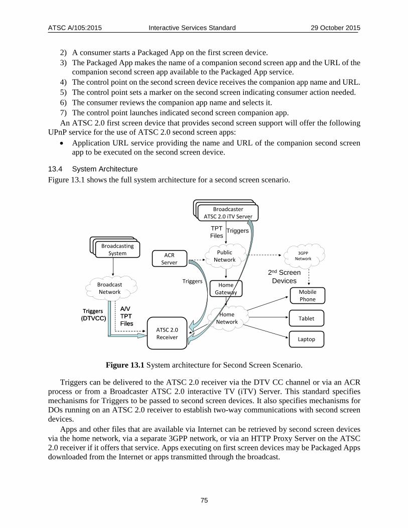
ATSC A/105:2015 Interactive Services Standard 29 October 2015
75
2) A consumer starts a Packaged App on the first screen device. 3) The Packaged App makes the name of a companion second screen app and the URL of the
companion second screen app available to the Packaged App service. 4) The control point on the second screen device receives the companion app name and URL. 5) The control point sets a marker on the second screen indicating consumer action needed. 6) The consumer reviews the companion app name and selects it. 7) The control point launches indicated second screen companion app. An ATSC 2.0 first screen device that provides second screen support will offer the following
UPnP service for the use of ATSC 2.0 second screen apps: • Application URL service providing the name and URL of the companion second screen
app to be executed on the second screen device.
13.4 System Architecture Figure 13.1 shows the full system architecture for a second screen scenario.
Figure 13.1 System architecture for Second Screen Scenario.
Triggers can be delivered to the ATSC 2.0 receiver via the DTV CC channel or via an ACR process or from a Broadcaster ATSC 2.0 interactive TV (iTV) Server. This standard specifies mechanisms for Triggers to be passed to second screen devices. It also specifies mechanisms for DOs running on an ATSC 2.0 receiver to establish two-way communications with second screen devices.
Apps and other files that are available via Internet can be retrieved by second screen devices via the home network, via a separate 3GPP network, or via an HTTP Proxy Server on the ATSC 2.0 receiver if it offers that service. Apps executing on first screen devices may be Packaged Apps downloaded from the Internet or apps transmitted through the broadcast.
ATSC 2.0Receiver
Tablet
BroadcastingSystem
BroadcastingSystem
BroadcastingSystem
Laptop
Triggers (DTVCC)
Home Gateway Mobile
Phone
2nd ScreenDevices
Home Network
ACRServer
A/VTPTFiles
TriggersBroadcastNetwork
BroadcasterATSC 2.0 iTVServer
BroadcasterATSC 2.0 iTVServer
BroadcasterATSC 2.0 iTV Server
Public Network
3GPPNetwork
TPTFiles
Triggers
Triggers (DTVCC)
A/VTPTFiles
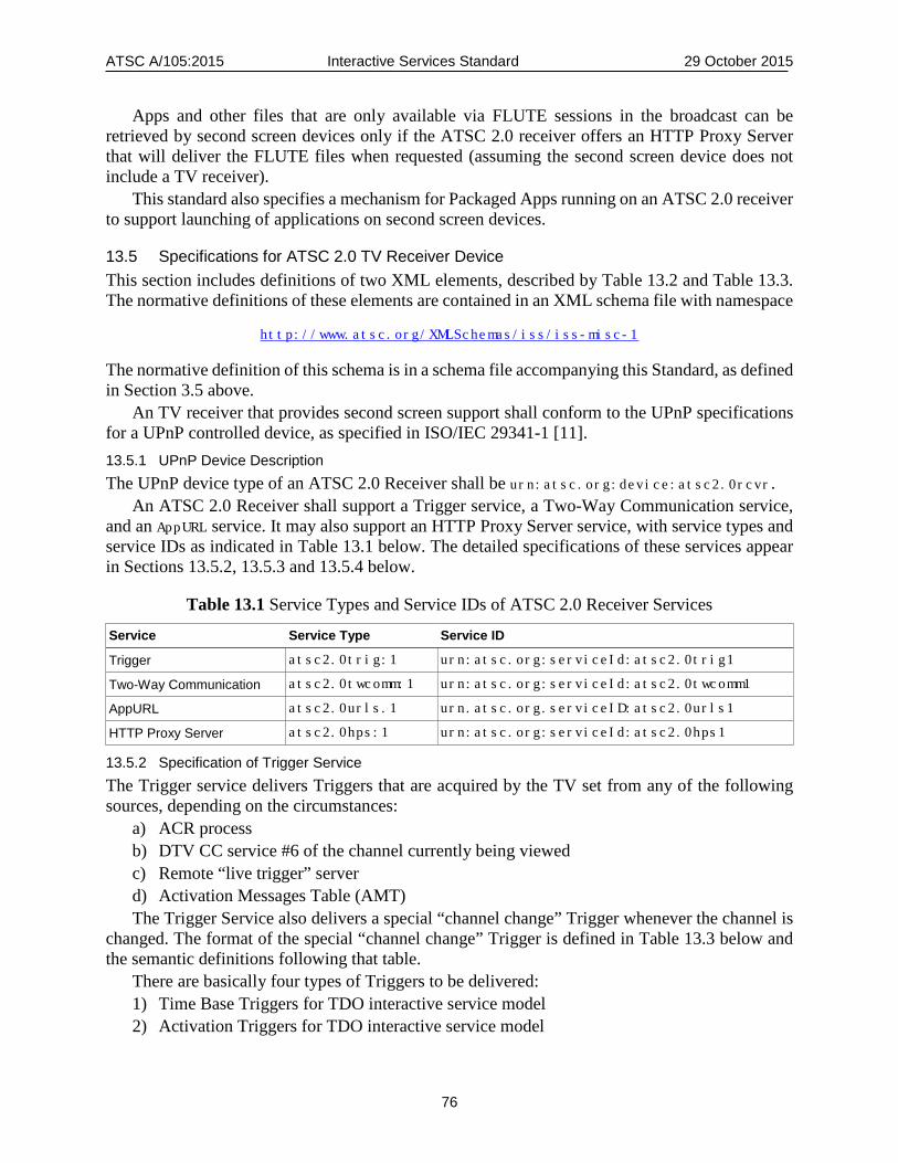
ATSC A/105:2015 Interactive Services Standard 29 October 2015
76
Apps and other files that are only available via FLUTE sessions in the broadcast can be retrieved by second screen devices only if the ATSC 2.0 receiver offers an HTTP Proxy Server that will deliver the FLUTE files when requested (assuming the second screen device does not include a TV receiver).
This standard also specifies a mechanism for Packaged Apps running on an ATSC 2.0 receiver to support launching of applications on second screen devices.
13.5 Specifications for ATSC 2.0 TV Receiver Device This section includes definitions of two XML elements, described by Table 13.2 and Table 13.3. The normative definitions of these elements are contained in an XML schema file with namespace
http://www.atsc.org/XMLSchemas/iss/iss-misc-1
The normative definition of this schema is in a schema file accompanying this Standard, as defined in Section 3.5 above.
An TV receiver that provides second screen support shall conform to the UPnP specifications for a UPnP controlled device, as specified in ISO/IEC 29341-1 [11]. 13.5.1 UPnP Device Description The UPnP device type of an ATSC 2.0 Receiver shall be urn:atsc.org:device:atsc2.0rcvr.
An ATSC 2.0 Receiver shall support a Trigger service, a Two-Way Communication service, and an AppURL service. It may also support an HTTP Proxy Server service, with service types and service IDs as indicated in Table 13.1 below. The detailed specifications of these services appear in Sections 13.5.2, 13.5.3 and 13.5.4 below.
Table 13.1 Service Types and Service IDs of ATSC 2.0 Receiver Services
Service Service Type Service ID
Trigger atsc2.0trig:1 urn:atsc.org:serviceId:atsc2.0trig1
Two-Way Communication atsc2.0twcomm:1 urn:atsc.org:serviceId:atsc2.0twcomm1
AppURL atsc2.0urls.1 urn.atsc.org.serviceID:atsc2.0urls1
HTTP Proxy Server atsc2.0hps:1 urn:atsc.org:serviceId:atsc2.0hps1
13.5.2 Specification of Trigger Service The Trigger service delivers Triggers that are acquired by the TV set from any of the following sources, depending on the circumstances:
a) ACR process b) DTV CC service #6 of the channel currently being viewed c) Remote “live trigger” server d) Activation Messages Table (AMT) The Trigger Service also delivers a special “channel change” Trigger whenever the channel is
changed. The format of the special “channel change” Trigger is defined in Table 13.3 below and the semantic definitions following that table.
There are basically four types of Triggers to be delivered: 1) Time Base Triggers for TDO interactive service model 2) Activation Triggers for TDO interactive service model
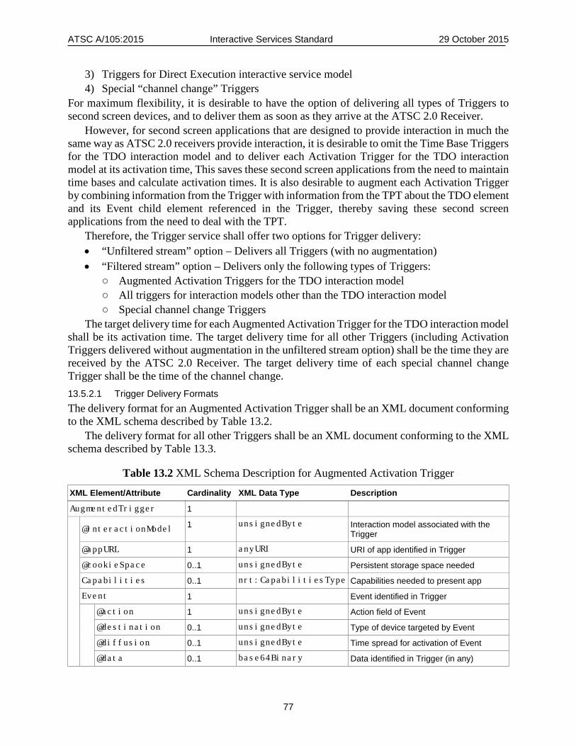
ATSC A/105:2015 Interactive Services Standard 29 October 2015
77
3) Triggers for Direct Execution interactive service model 4) Special “channel change” Triggers
For maximum flexibility, it is desirable to have the option of delivering all types of Triggers to second screen devices, and to deliver them as soon as they arrive at the ATSC 2.0 Receiver.
However, for second screen applications that are designed to provide interaction in much the same way as ATSC 2.0 receivers provide interaction, it is desirable to omit the Time Base Triggers for the TDO interaction model and to deliver each Activation Trigger for the TDO interaction model at its activation time, This saves these second screen applications from the need to maintain time bases and calculate activation times. It is also desirable to augment each Activation Trigger by combining information from the Trigger with information from the TPT about the TDO element and its Event child element referenced in the Trigger, thereby saving these second screen applications from the need to deal with the TPT.
Therefore, the Trigger service shall offer two options for Trigger delivery: • “Unfiltered stream” option – Delivers all Triggers (with no augmentation) • “Filtered stream” option – Delivers only the following types of Triggers:
○ Augmented Activation Triggers for the TDO interaction model ○ All triggers for interaction models other than the TDO interaction model ○ Special channel change Triggers
The target delivery time for each Augmented Activation Trigger for the TDO interaction model shall be its activation time. The target delivery time for all other Triggers (including Activation Triggers delivered without augmentation in the unfiltered stream option) shall be the time they are received by the ATSC 2.0 Receiver. The target delivery time of each special channel change Trigger shall be the time of the channel change. 13.5.2.1 Trigger Delivery Formats The delivery format for an Augmented Activation Trigger shall be an XML document conforming to the XML schema described by Table 13.2.
The delivery format for all other Triggers shall be an XML document conforming to the XML schema described by Table 13.3.
Table 13.2 XML Schema Description for Augmented Activation Trigger
XML Element/Attribute Cardinality XML Data Type Description
AugmentedTrigger 1
@interactionModel 1 unsignedByte Interaction model associated with the
Trigger
@appURL 1 anyURI URI of app identified in Trigger
@cookieSpace 0..1 unsignedByte Persistent storage space needed
Capabilities 0..1 nrt:CapabilitiesType Capabilities needed to present app
Event 1 Event identified in Trigger
@action 1 unsignedByte Action field of Event
@destination 0..1 unsignedByte Type of device targeted by Event
@diffusion 0..1 unsignedByte Time spread for activation of Event
@data 0..1 base64Binary Data identified in Trigger (in any)
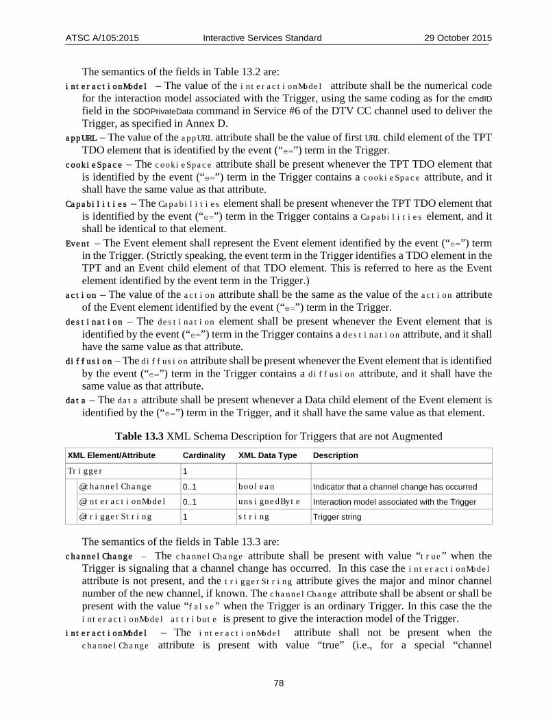
ATSC A/105:2015 Interactive Services Standard 29 October 2015
78
The semantics of the fields in Table 13.2 are: interactionModel – The value of the interactionModel attribute shall be the numerical code
for the interaction model associated with the Trigger, using the same coding as for the cmdID field in the SDOPrivateData command in Service #6 of the DTV CC channel used to deliver the Trigger, as specified in Annex D.
appURL – The value of the appURL attribute shall be the value of first URL child element of the TPT TDO element that is identified by the event (“e=”) term in the Trigger.
cookieSpace – The cookieSpace attribute shall be present whenever the TPT TDO element that is identified by the event (“e=”) term in the Trigger contains a cookieSpace attribute, and it shall have the same value as that attribute.
Capabilities – The Capabilities element shall be present whenever the TPT TDO element that is identified by the event (“e=”) term in the Trigger contains a Capabilities element, and it shall be identical to that element.
Event – The Event element shall represent the Event element identified by the event (“e=”) term in the Trigger. (Strictly speaking, the event term in the Trigger identifies a TDO element in the TPT and an Event child element of that TDO element. This is referred to here as the Event element identified by the event term in the Trigger.)
action – The value of the action attribute shall be the same as the value of the action attribute of the Event element identified by the event (“e=”) term in the Trigger.
destination – The destination element shall be present whenever the Event element that is identified by the event (“e=”) term in the Trigger contains a destination attribute, and it shall have the same value as that attribute.
diffusion – The diffusion attribute shall be present whenever the Event element that is identified by the event (“e=”) term in the Trigger contains a diffusion attribute, and it shall have the same value as that attribute.
data – The data attribute shall be present whenever a Data child element of the Event element is identified by the (“e=”) term in the Trigger, and it shall have the same value as that element.
Table 13.3 XML Schema Description for Triggers that are not Augmented
XML Element/Attribute Cardinality XML Data Type Description
Trigger 1 @channelChange 0..1 boolean Indicator that a channel change has occurred
@interactionModel 0..1 unsignedByte Interaction model associated with the Trigger
@triggerString 1 string Trigger string
The semantics of the fields in Table 13.3 are: channelChange – The channelChange attribute shall be present with value “true” when the
Trigger is signaling that a channel change has occurred. In this case the interactionModel attribute is not present, and the triggerString attribute gives the major and minor channel number of the new channel, if known. The channelChange attribute shall be absent or shall be present with the value “false” when the Trigger is an ordinary Trigger. In this case the the interactionModel attribute is present to give the interaction model of the Trigger.
interactionModel – The interactionModel attribute shall not be present when the channelChange attribute is present with value “true” (i.e., for a special “channel
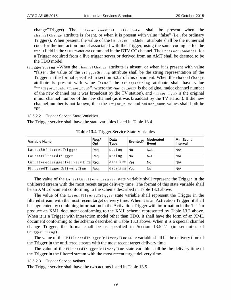
ATSC A/105:2015 Interactive Services Standard 29 October 2015
79
change”Trigger). The interactionModel attribute shall be present when the channelChange attribute is absent, or when it is present with value “false” (i.e., for ordinary Triggers). When present, the value of the interactionModel attribute shall be the numerical code for the interaction model associated with the Trigger, using the same coding as for the cmdID field in the SDOPrivateData command in the DTV CC channel. The interactionModel for a Trigger acquired from a live trigger server or derived from an AMT shall be deemed to be the TDO model.
triggerString –When the channelChange attribute is absent, or when it is present with value “false”, the value of the triggerString attribute shall be the string representation of the Trigger, in the format specified in section 6.2.2 of this document. When the channelChange attribute is present with value “true” the triggerString attribute shall have value “**<major_num>.<minor_num>”, where the <major_num> is the original major channel number of the new channel (as it was broadcast by the TV station), and <minor_num> is the original minor channel number of the new channel (as it was broadcast by the TV station). If the new channel number is not known, then the <major_num> and <minor_num> values shall both be “0”.
13.5.2.2 Trigger Service State Variables The Trigger service shall have the state variables listed in Table 13.4.
Table 13.4 Trigger Service State Variables
Variable Name Req./ Opt
Data Type Evented? Moderated
Event Min Event Interval
LatestUnfilteredTrigger Req. string No N/A N/A
LatestFilteredTrigger Req. string No N/A N/A
UnfilteredTriggerDeliveryTime Req. dateTime Yes No N/A
FilteredTriggerDeliveryTime Req. dateTime Yes No N/A
The value of the LatestUnfilteredTrigger state variable shall represent the Trigger in the unfiltered stream with the most recent target delivery time. The format of this state variable shall be an XML document conforming to the schema described in Table 13.3 above.
The value of the LatestFilteredTrigger state variable shall represent the Trigger in the filtered stream with the most recent target delivery time. When it is an Activation Trigger, it shall be augmented by combining information in the Activation Trigger with information in the TPT to produce an XML document conforming to the XML schema represented by Table 13.2 above. When it is a Trigger with interaction model other than TDO, it shall have the form of an XML document conforming to the schema described in Table 13.3 above. When it is a special channel change Trigger, the format shall be as specified in Section 13.5.2.1 (in semantics of triggerString).
The value of the UnfilteredTriggerDeliveryTime state variable shall be the delivery time of the Trigger in the unfiltered stream with the most recent target delivery time.
The value of the FilteredTriggerDeliveryTime state variable shall be the delivery time of the Trigger in the filtered stream with the most recent target delivery time. 13.5.2.3 Trigger Service Actions The Trigger service shall have the two actions listed in Table 13.5.
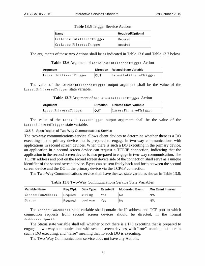
ATSC A/105:2015 Interactive Services Standard 29 October 2015
80
Table 13.5 Trigger Service Actions
Name Required/Optional
GetLatestUnfilteredTrigger Required
GetLatestFilteredTrigger Required
The arguments of these two Actions shall be as indicated in Table 13.6 and Table 13.7 below.
Table 13.6 Argument of GetLatestUnfilteredTrigger Action
Argument Direction Related State Variable
LatestUnfilteredTrigger OUT LatestUnfilteredTrigger
The value of the LatestUnfilteredTrigger output argument shall be the value of the LatestUnfilteredTrigger state variable.
Table 13.7 Argument of GetLatestFilteredTrigger Action
Argument Direction Related State Variable
LatestFilteredTrigger OUT LatestFilteredTrigger
The value of the LatestFilteredTrigger output argument shall be the value of the LatestFilteredTrigger state variable. 13.5.3 Specification of Two-Way Communications Service The two-way communications service allows client devices to determine whether there is a DO executing in the primary device that is prepared to engage in two-way communications with applications in second screen devices. When there is such a DO executing in the primary device, an application in a second screen device can request a TCP/IP connection, indicating that the application in the second screen device is also prepared to engage in two-way communication. The TCP/IP address and port on the second screen device side of the connection shall serve as a unique identifier of the second screen device. Bytes can be sent freely back and forth between the second screen device and the DO in the primary device via the TCP/IP connection.
The Two-Way Communications service shall have the two state variables shown in Table 13.8:
Table 13.8 Two-Way Communications Service State Variables
Variable Name Req./Opt. Data Type Evented? Moderated Event Min Event Interval
ConnectionAddress Required string Yes No N/A
Status Required boolean Yes No N/A
The ConnectionAddress state variable shall contain the IP address and TCP port to which connection requests from second screen devices should be directed, in the format <address>:<port>.
The Status state variable shall tell whether or not there is a DO executing that is prepared to engage in two-way communications with second screen devices, with “true” meaning that there is such a DO executing, and “false” meaning that no such DO is executing.
The Two-Way Communications service does not have any Actions.

ATSC A/105:2015 Interactive Services Standard 29 October 2015
81
The APIs used by a DO in the primary device to send and receive messages are defined in Section 7.2.2 of this standard. 13.5.4 Specification of AppURL Service The UPnP AppURL service allows second screen devices to determine the base URL and the name of the second screen application associated with the currently executing DO.
The UPnP AppURL service shall have two state variables, as described Table 13.9.
Table 13.9 AppURL Service State Variables
Variable Name Req/Opt Data Type Evented? Moderated Event Min Event Interval
AppURL Required string yes N/A N/A
AppName Required string yes N/A N/A
The value of the AppURL state variable shall be the base URL of the second screen application associated with the currently executing DO. When there is no DO with associated second screen application executing on the first screen device, the value of the AppURL state variable shall be the null string. The value of the AppName state variable shall be the name of the second screen application associated with the currently executing DO. When there is no DO with associated second screen application executing on the first screen device, the value of the AppName state variable shall be the null string.
Note: The values of the AppURL service are populated by the DO using the PublishURL class, defined below. When the current DO terminates, these values are reset to null.
The UPnP AppURL service shall have one Action, as described in Table 13.10 below.
Table 13.10 AppURL Service Action
Name Required/Optional
GetAppURL Required
The GetAppURL Action shall have two arguments, as described in Table 13.11 below.
Table 13.11 Arguments of GetAppURL Action
Argument Direction Related State Variable AppURL OUT AppURL AppName OUT AppName
The AppURL output argument shall be the current value of the AppURL state variable; and the AppName output argument shall be the current value of the AppName state variable. 13.5.5 Specification of HTTP Proxy Server Service The UPnP Proxy Server service provides an HTTP proxy server, to allow second screen devices to access files that are delivered to the TV receiver in the broadcast via FLUTE sessions, and to

ATSC A/105:2015 Interactive Services Standard 29 October 2015
82
make the retrieval of files from Internet servers by second screen devices more efficient in cases when multiple second screen devices in a household are retrieving the same files simultaneously.
The UPnP HTTP Proxy Server service shall have a single state variable, as described Table 13.12 below.
Table 13.12 Proxy Server Service State Variable
Variable Name Req/Opt Data Type Evented? Moderated Event Min Event Interval ProxyServerURL Required string no N/A N/A
The value of the ProxyServerURL state variable shall be the URL of the HTTP Proxy Server – i.e., the URL to which HTTP requests are to be directed in order to route the requests through the proxy server.
The UPnP Proxy Server service shall have a single Action, as described in Table 13.13 below.
Table 13.13 Proxy Server Service Action
Name Required/Optional
GetProxyURL Required
The GetProxyURL Action shall have a single argument, as described in Table 13.14.
Table 13.14 Arguments of GetProxyURL Action
Argument Direction Related State Variable
ProxyURL OUT ProxyServerURL
The ProxyURL output argument shall be the current value of the ProxyServerURL state variable. 13.5.6 Theory of Operation There are two modes of operation: one where a triggered application (TDO) executes on the TV receiver, and the other where a non-triggered application (Packaged App) executes on the TV receiver.
In the case of the triggered application executing on the TV receiver, when the programming currently being viewed on a TV receiver has an associated interactive data service with second screen support, a user of a second screen device can activate an appropriate application on the device. This application can go through the UPnP discovery and description process to discover the Trigger service, Two-Way Communications service, and Proxy Server service on the TV receiver.
The second screen application can then subscribe to UPnP “eventing” for the Trigger service to get notifications of Triggers ready for delivery, and it can use the GetLatestUnfilteredTrigger or GetLatestFilteredTrigger Action to get the Triggers it is designed to use. The result of this is that the second screen application will obtain the appropriate Triggers at the appropriate times. The application will then act on these Triggers in whatever manner it is designed to use.
The second screen application can also subscribe to UPnP “eventing” for the Two-Way Communications service to get notification of the TCP/IP address and port to use to request a connection for two-way communications, and notifications of when there is a DO executing in the
ATSC A/105:2015 Interactive Services Standard 29 October 2015
83
primary device that is prepared to communicate. The application can then engage in two-way communications with any DO that supports such communications.
The actions caused by Triggers and/or two-way communications will often require the second screen application to download files. These files might be available from HTTP servers on the Internet, or they might be available from a FLUTE session in the TV broadcast (or both).
If all the desired files are available via the Internet, and if the second screen device has good connectivity to the network, the application can simply retrieve the files directly.
If some or all of the desired files are available only via the TV broadcast, and if the ATSC 2.0 Receiver offers an HTTP Proxy Server service, then the application can get the proxy server URL with the GetProxyURL Action and retrieve the desired files via the proxy server. The application could also choose to use the proxy server in other situations where it might be more convenient to retrieve the files that way rather than directly.
In the case of the non-triggered application executing on the TV receiver, Regardless of the programming currently being viewed, a user can activate a DO on the TV receiver which, among other things, makes available the name and location of a companion application to be launched on a second screen device through the AppURL service.
A control point on the second screen device can subscribe to UPnP “eventing” associated with the AppURL service to get notification of changes to the AppURL and AppName variables. The control point would then indicate to the user of the second screen device that an available service is pending. Subsequently, the user would view the AppName and select the service, resulting in the companion second screen application being launched on the second screen device.
Second screen applications may be associated with a DO executing on the ATSC 2.0 receiver, even when that DO is a broadcaster-provided Packaged App previously downloaded to the ATSC 2.0 receiver whose life cycle is controlled by the consumer instead of by the broadcaster. In the absence of triggers to identify a companion second screen application, the ATSC 2.0 receiver offers an AppURL service that allows a control point on the second screen device to use a GetAppURL action to access a published second screen application URL and launch it on the second screen device.
14. DELIVERY VIA OTHER INTERFACES SUPPORT This section describes an architecture and protocols for delivery of ATSC 2.0 interactive adjunct data services (hereafter called “interactive services”) to receivers in environments where access to the ATSC emission stream consists only of uncompressed audio and video (for example, as received from a cable or satellite set-top box). The architecture and protocols are designed to be used by receivers that have Internet connections and that only have access to the uncompressed audio and video from the broadcast stream. Of course, the architecture and protocols can only be used successfully if the interactive service provider chooses to support them.
14.1 Introduction and Architecture The architecture is designed to support two basic approaches to identifying the content being viewed, so that any associated ATSC 2.0 data enhancements can be delivered via Internet:
• Watermarking • Fingerprinting In both the watermarking and fingerprinting approaches the intent is to allow receivers to find
out the channel currently being watched, the location in time of the currently watched frames in
ATSC A/105:2015 Interactive Services Standard 29 October 2015
84
the channel, and a URL that can be used as the starting point to get additional information as needed.
In the watermarking (WM) approach the broadcaster inserts watermarks into the broadcast audio or video frames. These watermarks are designed to carry a modest amount of information to receivers, while being imperceptible or at least minimally intrusive to viewers. Such watermarks might provide directly the channel, timing and URL information that receivers need, or they might only provide identifying information that receivers can send via an Internet connection to a remote server in order to get the channel, timing and URL information they need.
In the fingerprinting (FP) approach receivers extract fingerprints (also called signatures) from audio or video frames and send these via an Internet connection to a remote server, which checks the fingerprints against a database of fingerprints of broadcast frames from multiple broadcasters, and returns the channel, timing and URL information the receivers need.
In both WM and FP cases receivers use the URL as a starting point to get ATSC 2.0 content, including triggers, using the steps and protocols defined in Section 14.2.
In both WM and FP cases the timing information is in the form of a timestamp relative to a broadcast side clock that is used for specification of the timing of time critical events for the channel, such as activation timestamps in triggers delivered over the Internet.
It is assumed that broadcasters will typically support delivery of ATSC 2.0 services directly in the broadcast stream, for the benefit of receivers that get TV signals from antennas, and also support delivery of ATSC 2.0 services over the Internet as described above, for the benefit of receivers that get uncompressed audio and video, but have an Internet connection. However, nothing in this document prevents broadcasters from supporting either one of these two delivery mechanisms without the other.
Figure 15.1illustrate typical architectures for the watermarking (WM) approach, in the case when the watermark provides directly the information that receivers need.

ATSC A/105:2015 Interactive Services Standard 29 October 2015
85
Figure 15.1 Architecture for WM approach.
Figure 15.2illustrates a typical architecture for the fingerprinting (FP) approach.
Figure 15.2 Architecture for FP approach.
A typical architecture for the watermarking approach in the case when the watermark provides only a code value would look something like a combination of the two architectures in Figure 15.1 and Figure 15.2. There would be a Watermark Inserter, as in Figure 15.1, but it would insert a
Broadcaster
(WM-capable)ATSC 2.0 Receiver
MVPD(Multichannel
Video Program
Distributor)
Audio/Video Data
Audio/Video
Data & Signaling Content
Server
Internet
STB UncompressedAudio/Video
Signaling
WatermarkInserter
WMClient
ExtractsChanTimeURL
InsertsChanTimeURL Data &
Signaling Query
Broadcaster
ATSC 2.0 Receiver(FP-capable)
ChanTimeURL
MVPD(Multichannel
Video Program
Distributor)
FP Server
Audio/Video
Data
Audio/Video
Data &Signaling Content
Server
Internet
Signature
STB UncompressedAudio/Video
FPClient
SignatureExtractor
Signatures + Metadata
Data &Signaling
Query

ATSC A/105:2015 Interactive Services Standard 29 October 2015
86
code, rather than the information needed by receivers. There would also be a WM Server, playing much the same role as the FP Server in Figure 15.2. Receivers would send it codes, rather than signatures, and they would get back the information they need.
14.2 Accessing ATSC 2.0 Interactive Services There are a number of different ways for a receiver in an ACR environment to access ATSC 2.0 interactive services, depending on broadcaster choices and the nature of the ACR system. The interactive service model can be the Direct Execution model or the TDO model. In the case of the TDO model, Triggers can be delivered independently of the ACR Server, or they can be delivered by the ACR Server. Each of these different ways, and the steps for accessing the interactive services for each one, are described in the following sections. 14.2.1 Direct Execution Model An ACR process for a virtual channel that contains an ATSC 2.0 interactive service which has the Direct Execution Model shall provide to receivers viewing that channel the equivalent of Time Base Triggers that include the Media Time (“m=”) term and the contentID (“c=”) term. These Triggers shall be identified by means of some kind of message header as Triggers for an interactive service with the Direct Execution model.
When a receiver first receives such a Trigger with a new locator_part, it is expected to load into its browser the Declarative Object (DO) pointed to by the locator_part of the Trigger. Typically the DO will have been pre-installed or previously downloaded and cached. Otherwise the receiver is expected to download it, using an HTTP GET request.)
The DO will then contact the appropriate back-end server and provide the interactive service as directed by the back-end server.
The receiver is expected to make that initial Trigger and subsequent Triggers available to the DO as they are obtained, using the API defined in Section 7.2 of this document for that purpose, until such time as it gets a Trigger from the ACR server that has a new locator_part and/or that is identified as a Trigger for an interactive service with the TDO model (either of which typically indicates a channel change). 14.2.2 TDO Model with Activations Independent of ACR System An ACR process for a virtual channel that contains an ATSC 2.0 interactive service which has the TDO model, and which provides event activations independently of the ACR Server, shall provide to receivers viewing that channel the equivalent of Time Base Triggers that include the media_time (“m=”) term. These Triggers shall be identified by means of some kind of message header as Triggers for an interactive service with the TDO model.
When a receiver first receives such a Trigger with a new locator_part, it is expected to retrieve the current TDO Parameters Table (TPT) from the TPT Server pointed to by the locator_part of the Trigger, and to use the Media Time in that Trigger and subsequent Triggers to establish a reference time base for event activations, relative to the audio or video frames identified by the ACR process.
If an Activation Messages Table (AMT) is delivered along with the TPT, the receiver is expected to use the individual Activation elements in the table to activate events at the correct times relative to the time base established by the media-time terms in the Triggers. (These events can include loading and executing a TDO, causing a TDO to take a particular synchronized action, suspend a TDO, etc.)
ATSC A/105:2015 Interactive Services Standard 29 October 2015
87
If a LiveTrigger element is included in the TPT, the receiver is expected to retrieve Activation Triggers from the Live Trigger Server identified by the URL in the LiveTrigger element, using the polling method signaled in the LiveTrigger element, and to use these Activation Triggers to activate events at the correct times relative to the time base established by the media-time terms in the Triggers.
Note that both an AMT and a Live Trigger Server can be used for the same service, typically with the former providing static activations and the latter providing dynamic activations. Alternatively, an AMT can be used alone when all activations for the segment are static, or a Live Trigger Server can be used alone to deliver both static and dynamic activations. 14.2.3 TDO Model with Activations Received from ACR System This section describes how Activation Triggers for a TDO interactive service model can be delivered efficiently to receivers in an ACR environment, without the need for a separate Trigger server.
Fingerprinting ACR systems always include an ACR server. Receivers send frame signatures to an ACR server, and the ACR server identifies the frame represented by the signature and sends back the information needed by the receivers. Watermarking ACR systems include an ACR server in the case when the watermarks consist of no more that codes that can be sent to an ACR server to get the information needed by receivers. Watermarking ACR systems do not include an ACR server in the case when the watermarks themselves contain the information needed by receivers. In those ACR systems that include an ACR server, two different models are used for communication between the ACR servers and receivers: a request/response model and an event-driven model. These two cases are considered separately here, since the way in which activations can be delivered to receivers is different in the two cases.
It is assumed in this section that the broadcaster is supporting the TDO interaction model. Three separate cases are considered:
• ACR Server using request/response model • ACR Server using event driven model • Watermarking ACR system inserting information directly In the cases with an ACR server, the ACR method could be fingerprinting, in which case
receivers compute some sort of signature (or fingerprint) of audio or video frames and submit them to an ACR server for identification, or it could be watermarking, in which case receivers extract codes in the form of watermarks from the audio or video frames and submit the codes to an ACR server for identification. This specification will use the terminology of fingerprinting signatures, but the system would work the same for watermarking codes. 14.2.3.1 ACR Server Using Request/Response Model In the request/response ACR model the receiver is expected to generate signatures of the content periodically (e.g. every 5 seconds) and send requests containing the signatures to the ACR server. When the ACR server gets a request from a receiver, it returns a response. The communications session is not kept open between request/response instances. In this model, it is not feasible for the ACR server to initiate messages to the client.
For an ACR server that is using this request/response model and is delivering Activation Triggers to receivers, each response from the ACR server shall be one of the following:
• Null • Time Base Trigger
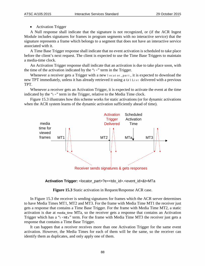
ATSC A/105:2015 Interactive Services Standard 29 October 2015
88
• Activation Trigger A Null response shall indicate that the signature is not recognized, or (if the ACR Ingest
Module includes signatures for frames in program segments with no interactive service) that the signature represents a frame which belongs to a segment that does not have an interactive service associated with it.
A Time Base Trigger response shall indicate that no event activation is scheduled to take place before the client’s next request. The client is expected to use the Time Base Triggers to maintain a media-time clock.
An Activation Trigger response shall indicate that an activation is due to take place soon, with the time of the activation indicated by the “t=” term in the Trigger.
Whenever a receiver gets a Trigger with a new locator_part, it is expected to download the new TPT immediately, unless it has already retrieved it using a UrlList delivered with a previous TPT.
Whenever a receiver gets an Activation Trigger, it is expected to activate the event at the time indicated by the “t=” term in the Trigger, relative to the Media Time clock.
Figure 15.3 illustrates how this scheme works for static activations (or for dynamic activations when the ACR system learns of the dynamic activation sufficiently ahead of time).
Figure 15.3 Static activation in Request/Response ACR case.
In Figure 15.3 the receiver is sending signatures for frames which the ACR server determines to have Media Times MT1, MT2 and MT3. For the frame with Media Time MT1 the receiver just gets a response that contains a Time Base Trigger. For the frame with Media Time MT2, a static activation is due at media_time MTa, so the receiver gets a response that contains an Activation Trigger which has a “t=MTa” term. For the frame with Media Time MT3 the receiver just gets a response that contains a Time Base Trigger.
It can happen that a receiver receives more than one Activation Trigger for the same event activation. However, the Media Times for each of them will be the same, so the receiver can identify them as duplicates, and only apply one of them.
Activation Trigger: <locator_part>?e=<tdo_id>.<event_id>&t=MTa
Receiver sends signatures & gets responses
ScheduledActivation
Timemedia time for viewed frames MT1 MT3MT2 MTa
ActivationTrigger
Delivered
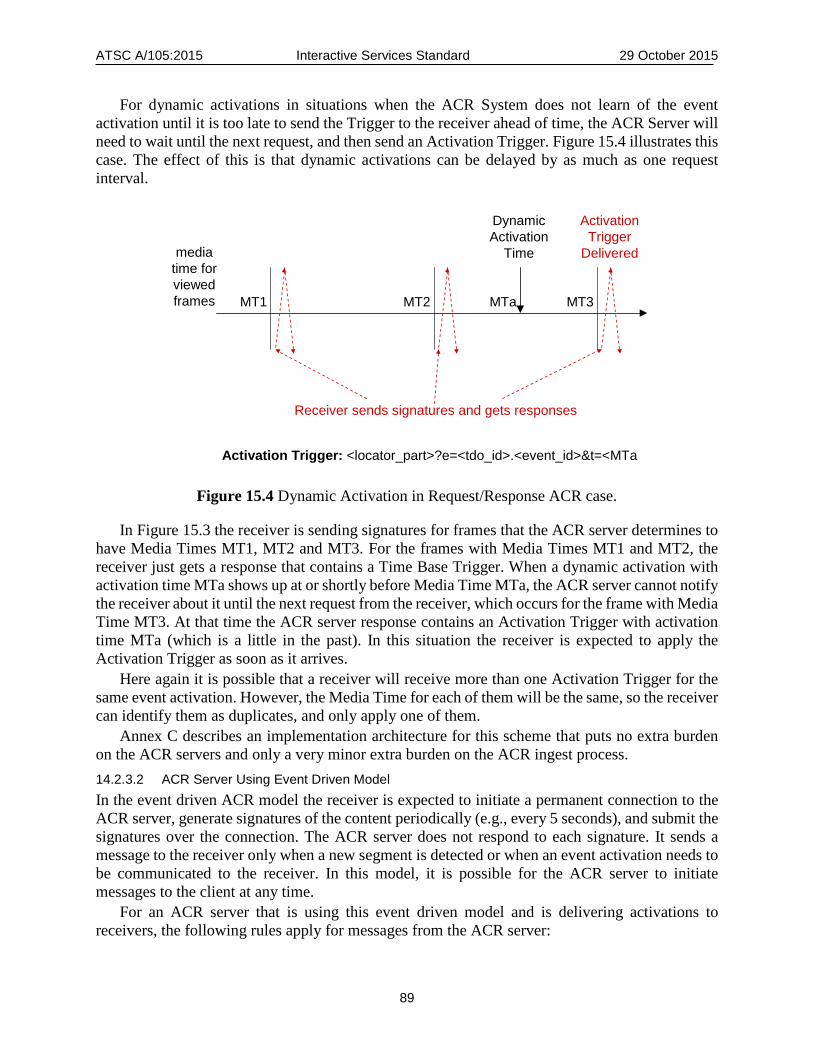
ATSC A/105:2015 Interactive Services Standard 29 October 2015
89
For dynamic activations in situations when the ACR System does not learn of the event activation until it is too late to send the Trigger to the receiver ahead of time, the ACR Server will need to wait until the next request, and then send an Activation Trigger. Figure 15.4 illustrates this case. The effect of this is that dynamic activations can be delayed by as much as one request interval.
Activation Trigger: <locator_part>?e=<tdo_id>.<event_id>&t=<MTa
Receiver sends signatures and gets responses
ActivationTrigger
Delivered
DynamicActivation
Time
MT1 MT3MT2 MTa
media time for viewed frames
Figure 15.4 Dynamic Activation in Request/Response ACR case.
In Figure 15.3 the receiver is sending signatures for frames that the ACR server determines to have Media Times MT1, MT2 and MT3. For the frames with Media Times MT1 and MT2, the receiver just gets a response that contains a Time Base Trigger. When a dynamic activation with activation time MTa shows up at or shortly before Media Time MTa, the ACR server cannot notify the receiver about it until the next request from the receiver, which occurs for the frame with Media Time MT3. At that time the ACR server response contains an Activation Trigger with activation time MTa (which is a little in the past). In this situation the receiver is expected to apply the Activation Trigger as soon as it arrives.
Here again it is possible that a receiver will receive more than one Activation Trigger for the same event activation. However, the Media Time for each of them will be the same, so the receiver can identify them as duplicates, and only apply one of them.
Annex C describes an implementation architecture for this scheme that puts no extra burden on the ACR servers and only a very minor extra burden on the ACR ingest process. 14.2.3.2 ACR Server Using Event Driven Model In the event driven ACR model the receiver is expected to initiate a permanent connection to the ACR server, generate signatures of the content periodically (e.g., every 5 seconds), and submit the signatures over the connection. The ACR server does not respond to each signature. It sends a message to the receiver only when a new segment is detected or when an event activation needs to be communicated to the receiver. In this model, it is possible for the ACR server to initiate messages to the client at any time.
For an ACR server that is using this event driven model and is delivering activations to receivers, the following rules apply for messages from the ACR server:

ATSC A/105:2015 Interactive Services Standard 29 October 2015
90
• When the ACR server receives a signature from a receiver that corresponds to a new segment, the ACR server shall immediately send a Time Base Trigger to the receiver, just to enable the receiver to obtain the associated TPT.
• Whenever an event is due to be activated, the ACR server shall send an Activation Trigger to the receiver. If possible, it shall send the Activation Trigger slightly ahead of the time when the receiver needs to apply it. (This is very similar to the behavior in the request/response model.) If the ACR server learns of the activation so late that it cannot send an Activation Trigger very much ahead of time (which can happen in the case of a dynamic event activation), it shall still send an Activation Trigger as soon as it can,. In this latter case, it is possible that the client will get the message slightly after the activation time, because of message delays, in which case it is expected to activate the event immediately upon receipt of the message.
Whenever a receiver gets a Trigger with a new locator_part, it is expected to download the new TPT immediately, unless it already retrieved it using a UrlList delivered with a previous TPT.
14.3 Watermarking ACR System Inserting Information Directly In the case of a watermarking system that inserts the information receivers need directly, the watermark associated with a frame shall follow the same rules as stated above for what a request/response ACR server would return for that frame.
Annex C describes an implementation architecture for the scheme described in this section that puts no extra burden on the ACR servers and only a very minor extra burden on the ACR ingest process.
14.4 Support for Stand-alone NRT Services In order for a receiver in an ACR environment to get access to stand-alone NRT services, the broadcaster needs to support Internet access to the NRT services, and the receiver needs to obtain the SMT and the NRT-IT instances for the services.
Section 15 of this standard defines a query protocol for obtaining PSIP tables and NRT tables via the Internet. If a broadcaster supports this protocol for a particular broadcast stream, then a receiver that knows the URL of the broadcaster’s Signaling Server for that broadcast stream can take the following steps:
1) Issue a query for the “Basic NRT Set” of tables for the broadcast stream, for a specified future time interval (for example, the next 12 hours).
2) This will produce the SMT and ILT for each of the stand-alone NRT virtual channels, and the NRT-IT and TFT instances covering the specified time interval.
One way a receiver can discover the URL of the Signaling Server for a broadcast stream is that the provider of an interactive service segment in the broadcast stream can choose to provide the Signaling Server URL in a UrlList element delivered along with the TPT.
One disadvantage of this method is that if a receiver is never tuned to an A/V channel of a particular broadcaster, it will not discover the stand-alone NRT services of that broadcaster.
Another way a receiver can discover URLs of Signaling Servers is by pre-configuration. In the same way that a DTV receiver manufacturer can pre-configure a DTV receiver to know how to find an ACR Server covering any particular broadcast area, a DTV receiver manufacturer can pre-configure a DTV receiver to know how to find an “NRT Discovery Server” covering any particular

ATSC A/105:2015 Interactive Services Standard 29 October 2015
91
broadcast area. Such an NRT Discovery Server would be able to give the receiver a list of the broadcast streams that contain stand-alone NRT services, along with the Signaling Server URL for each one.
15. INTERNET DELIVERY OF SIGNALING AND ANNOUNCEMENTS This section specifies two mechanisms to enhance access to signaling and announcements:
1) A protocol for Internet delivery of PSIP tables (defined in A/65 [9]) and NRT tables (defined in the A/103 [2]), using HTTP [4];
2) An “NRT Services Summary Descriptor” which can appear in a VCT or an EIT instance to allow EPG applications in receivers to get information about adjunct NRT services or stand-alone NRT services without having to dig down into the IP subnet of the virtual channel containing them (or to retrieve and parse the NRT tables if the signaling and announcements are being retrieved via Internet).
15.1 Internet Delivery of Signaling and Announcements When supported by broadcasters, the protocol specified in this subsection provides two capabilities:
• For devices that get DTV broadcast signals via a path that delivers only uncompressed audio and video, this protocol is typically the only way for them to access a broadcaster’s stand-alone NRT services.
• Even for a device that has access to the full broadcast stream, this protocol provides a way to retrieve data for populating a Program/Service Guide without cycling through all the broadcast streams available in the local broadcast area and waiting for the desired tables to show up. It also allows retrieval of such data at any time, even while a viewer is watching TV, without needing a separate tuner.
Section 15.1.1 specifies the HTTP request format for this protocol. Section 15.1.2 specifies the HTTP response format. 15.1.1 HTTP Request Format The tables covered by this specification are:
• PSIP tables: TVCT, EIT, ETT • NRT tables: SMT, NRT-IT, TFT, PIT, and PTCT
The full URL to be supported for each retrieval request shall consist of three parts: • Base URL • Appropriate query term(s) from Table 18.1 below to indicate the desired time interval and
update mode • Appropriate query term(s) from Table 18.2 below to indicate the table(s) desired The base URL is specific to a particular broadcast stream (transport stream). There are several
methods by which the base URL can be made available to receivers in different situations: • For receivers that have access to the DTV CC channel, the broadcaster can deliver the base
URL in DTV CC service #6, as specified in Annex D. • For receivers that use the Internet to retrieve TPTs for the broadcaster’s adjunct interactive
data services, the broadcaster can deliver the base URL along with the TPTs, as specified in Section 6 of this document.
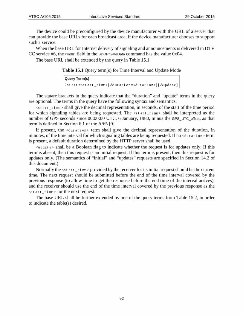
ATSC A/105:2015 Interactive Services Standard 29 October 2015
92
The device could be preconfigured by the device manufacturer with the URL of a server that can provide the base URLs for each broadcast area, if the device manufacturer chooses to support such a service.
When the base URL for Internet delivery of signaling and announcements is delivered in DTV CC service #6, the cmdID field in the SDOPrivateData command has the value 0x04.
The base URL shall be extended by the query in Table 15.1.
Table 15.1 Query term(s) for Time Interval and Update Mode
Query Term(s) ?start=<start_time>[&duration=<duration>][&update]
The square brackets in the query indicate that the “duration” and “update” terms in the query are optional. The terms in the query have the following syntax and semantics.
<start_time> shall give the decimal representation, in seconds, of the start of the time period for which signaling tables are being requested. The <start_time> shall be interpreted as the number of GPS seconds since 00:00:00 UTC, 6 January, 1980, minus the GPS_UTC_offset, as that term is defined in Section 6.1 of the A/65 [9].
If present, the <duration> term shall give the decimal representation of the duration, in minutes, of the time interval for which signaling tables are being requested. If no <duration> term is present, a default duration determined by the HTTP server shall be used.
<update> shall be a Boolean flag to indicate whether the request is for updates only. If this term is absent, then this request is an initial request. If this term is present, then this request is for updates only. (The semantics of “initial” and “updates” requests are specified in Section 14.2 of this document.)
Normally the <start_time> provided by the receiver for its initial request should be the current time. The next request should be submitted before the end of the time interval covered by the previous response (to allow time to get the response before the end time of the interval arrives), and the receiver should use the end of the time interval covered by the previous response as the <start_time> for the next request.
The base URL shall be further extended by one of the query terms from Table 15.2, in order to indicate the table(s) desired.

ATSC A/105:2015 Interactive Services Standard 29 October 2015
93
Table 15.2 Query terms for Signaling Table Requests
Table(s) Requested Query Term(s)
PSIP Set ?table=PSIP
VCT ?table=VCT
EIT ?table=EIT[&chan=<chan_id>]
ETT ?table=ETT[&chan=<chan_id>][&etmid=<ETM_id>]
Basic NRT Set ?table=BASIC-SET[&chan=<chan_id>]
Extended NRT Set ?table=EXT-SET[&chan=<chan_id>]
SMT ?table=SMT[&chan=<chan_id>]
NRT-IT ?table=NRT-IT[&chan=<chan_id>] [&svc=<svc_id>]
TFT ?table=TFT[&chan=<chan_id>] [&svc=<svc_id>]
PIT and PTCT ?table=PIT+PTCT[&chan=<chan_id>]
Items in square brackets in Table 15.2 ([…]) indicate optional query terms. The optional query terms have the following syntax and semantics.
When present, <chan_id> shall give the channel number of a specific virtual channel for which tables are requested, in the form of the decimal representation of the major channel number, followed by a dot (‘.’), followed by the decimal representation of the minor channel number. If this query term is not present, that shall indicate that the request is for tables for all virtual channels in the broadcast stream.
When present, <ETM_id> shall give the decimal representation of the ETM_id of the specific ETT instance requested, as defined in Table 6.14 of the A/65 [9]. If this query term is not present, that shall indicate that the request is for all ETT instances within the scope of the other query terms in the request.
When present, <svc_id> shall give the service ID of a specific NRT service in the broadcast stream for which tables are requested, in the form of the decimal representation of the high order byte, followed by a dot (‘.’), followed by the decimal representation of the low order byte. If this term is not present, that shall indicate that the request is for tables for all NRT services within the scope of the other query terms in the request.
The “PSIP Set” tables shall consist of the TVCT, and the EIT and ETT instances for all virtual channels in the broadcast stream.
The “Basic NRT Set” tables shall consist of the SMT, plus the NRT-IT and TFT instances for all NRT services in the virtual channel.
The “Extended NRT Set” tables shall consist of the tables in the Basic Set plus the PIT and the PTCT.
Requests for EIT, ETT, NRT-IT and/or TFT tables shall mean the instances of these tables which cover the time interval specified by the <start_time> and <duration> specified in the query (or the default <duration> if no <duration> term is present in the query). 15.1.2 HTTP Response The response to a receiver request shall begin with the phrase “Duration=<duration>”, where <duration> is the decimal representation of the duration of the time interval covered by the response, in minutes, followed by a newline character. The duration should be the requested
ATSC A/105:2015 Interactive Services Standard 29 October 2015
94
duration, if one was present. If no duration was present in the request, it shall be a default duration set by the Signaling Server.
For an initial request, the remainder of the response following the beginning phrase shall be the concatenated set of all the requested signaling tables or blocks that are in effect at the time <start_time>, followed by any updates or new instances of the requested signaling tables or blocks that are scheduled to take effect during the time interval of length <duration> minutes, starting from time <start_time>, arranged in the order in which they are scheduled to take effect.
For an update request, the response following the beginning phrase shall be the concatenated set of any updates or new instances of the requested signaling tables or blocks that are scheduled to take effect during the time interval of length <duration> minutes, starting from time <start_time>, arranged in the order in which they are scheduled to take effect. Any table instances that were in effect before the <start_time> shall not be included. For the purpose of ordering interactive adjunct service signaling blocks, the time a block takes effect is the time its underlying A/V segment begins.
The PSIP or NRT tables or table instances that are returned shall have exactly the same format as they would have if transmitted in the broadcast stream. If a table or table instance comprises multiple sections, the sections shall appear in the response concatenated together in order.
Each PSIP or NRT signaling table section delivered in the response shall be preceded by a 32-bit unsigned integer giving the decimal representation, in seconds, of the update time of the signaling table section (i.e., the time the signaling table section comes into effect, or came into effect). The update time value shall be interpreted as the number of GPS seconds since 00:00:00 UTC, 6 January, 1980, minus the GPS_UTC_offset, as that term is defined in Section 6.1 of A/65 [9]. No duplicate signaling table section shall be included in a single response (but of course a new version of a table is not considered to be a duplicate).
For both initial requests and update requests, the server shall close the HTTP session after the response.
15.2 NRT Services Summary Descriptor The NRT Services Summary Descriptor defined in this subsection can be used to provide the following information:
• Indication of the presence of adjunct NRT services for an audio/video (A/V) virtual channel or event, together with an indication whether the adjunct services are access controlled.
• Listing of NRT services in an NRT virtual channel, together with an indication whether they are access controlled.
An NRT Services Summary Descriptor may appear in a channel level descriptor loop in a VCT (TVCT or CVCT), or in an event level descriptor loop in an EIT. This allows receivers to display information about data services and enhancements in the Program/Service Guide using these PSIP tables alone, without needing to dig down into the IP subnet of each virtual channel to extract the data.
An NRT Capabilities Descriptor may be used in conjunction with an NRT Services Summary Descriptor in a VCT or EIT to indicate the capabilities needed to provide a meaningful presentation of the NRT service(s) in the virtual channel or event. If the receiver does not have the requisite capabilities, it could choose not to indicate the presence of the NRT service(s) in the Program Guide.
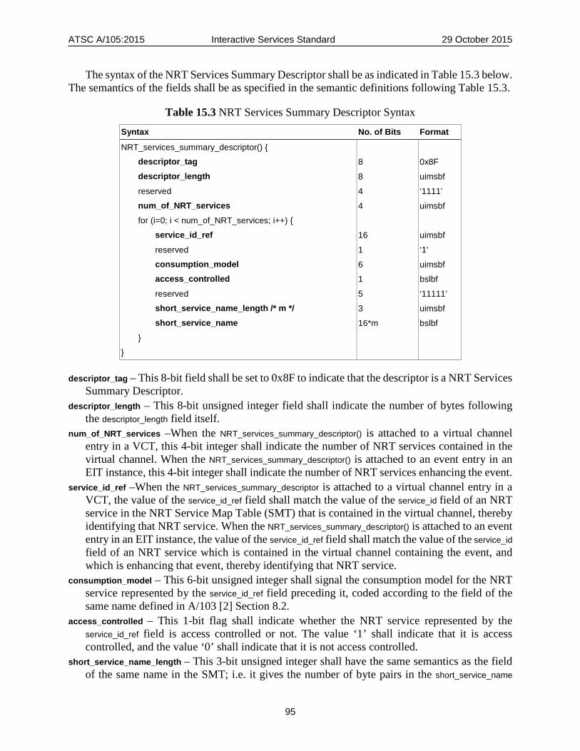
ATSC A/105:2015 Interactive Services Standard 29 October 2015
95
The syntax of the NRT Services Summary Descriptor shall be as indicated in Table 15.3 below. The semantics of the fields shall be as specified in the semantic definitions following Table 15.3.
Table 15.3 NRT Services Summary Descriptor Syntax
Syntax No. of Bits Format
NRT_services_summary_descriptor() { descriptor_tag 8 0x8F descriptor_length 8 uimsbf
reserved 4 ‘1111’ num_of_NRT_services 4 uimsbf
for (i=0; i < num_of_NRT_services; i++) { service_id_ref 16 uimsbf
reserved 1 ‘1’ consumption_model 6 uimsbf access_controlled 1 bslbf
reserved 5 ‘11111’ short_service_name_length /* m */ 3 uimsbf short_service_name 16*m bslbf
}
}
descriptor_tag – This 8-bit field shall be set to 0x8F to indicate that the descriptor is a NRT Services Summary Descriptor.
descriptor_length – This 8-bit unsigned integer field shall indicate the number of bytes following the descriptor_length field itself.
num_of_NRT_services –When the NRT_services_summary_descriptor() is attached to a virtual channel entry in a VCT, this 4-bit integer shall indicate the number of NRT services contained in the virtual channel. When the NRT_services_summary_descriptor() is attached to an event entry in an EIT instance, this 4-bit integer shall indicate the number of NRT services enhancing the event.
service_id_ref –When the NRT_services_summary_descriptor is attached to a virtual channel entry in a VCT, the value of the service_id_ref field shall match the value of the service_id field of an NRT service in the NRT Service Map Table (SMT) that is contained in the virtual channel, thereby identifying that NRT service. When the NRT_services_summary_descriptor() is attached to an event entry in an EIT instance, the value of the service_id_ref field shall match the value of the service_id field of an NRT service which is contained in the virtual channel containing the event, and which is enhancing that event, thereby identifying that NRT service.
consumption_model – This 6-bit unsigned integer shall signal the consumption model for the NRT service represented by the service_id_ref field preceding it, coded according to the field of the same name defined in A/103 [2] Section 8.2.
access_controlled – This 1-bit flag shall indicate whether the NRT service represented by the service_id_ref field is access controlled or not. The value ‘1’ shall indicate that it is access controlled, and the value ‘0’ shall indicate that it is not access controlled.
short_service_name_length – This 3-bit unsigned integer shall have the same semantics as the field of the same name in the SMT; i.e. it gives the number of byte pairs in the short_service_name

ATSC A/105:2015 Interactive Services Standard 29 October 2015
96
field that follows it. The value of this field should be 0 except when it is attached to a virtual channel with service_type 0x08 (since it is not useful to display the service name of adjunct NRT services in a Program Guide).
short_service_name – This variable length field shall have the same syntax and semantics as the field of the same name in the SMT; i.e., it gives the short name of the NRT service represented by the service_id_ref field.

ATSC A/105:2015 Interactive Services Standard, Annex A 29 October 2015
97
Annex A: OIPF DAE Specification Profile
A.1 SCOPE Annex A defines a profile of the OIPF Declarative Application Environment.
A.2 DAE REQUIREMENTS Mandatory and optional provisions of the DAE shall be as defined in Table A.1 below.
A.3 DETAILED SECTION BY SECTION DEFINITION Table A.1 below, adapted from Table A.1 of the HbbTV specification, TS 102 796 [16], indicates certain portions of the OIPF DAE specification [12] that are to be supported in the ATSC 2.0 Interactive Services standard, as specified in Section 7 of this document. The present document includes by reference a subset of the OIPF specification which is a strict subset of that which is required by HbbTV. It additionally includes by reference elements taken from HbbTV. The relationship of the specifications is illustrated by the Venn diagram in Figure A.1.
OIPF
HbbTV
ATSC 2.0
Figure A.1 Relationship between OIPF, HbbTV and ATSC 2.0.

ATSC A/105:2015 Interactive Services Standard, Annex A 29 October 2015
98
Table A.1 Section-by-section Profile of HbbTV/OIPF DAE Specification
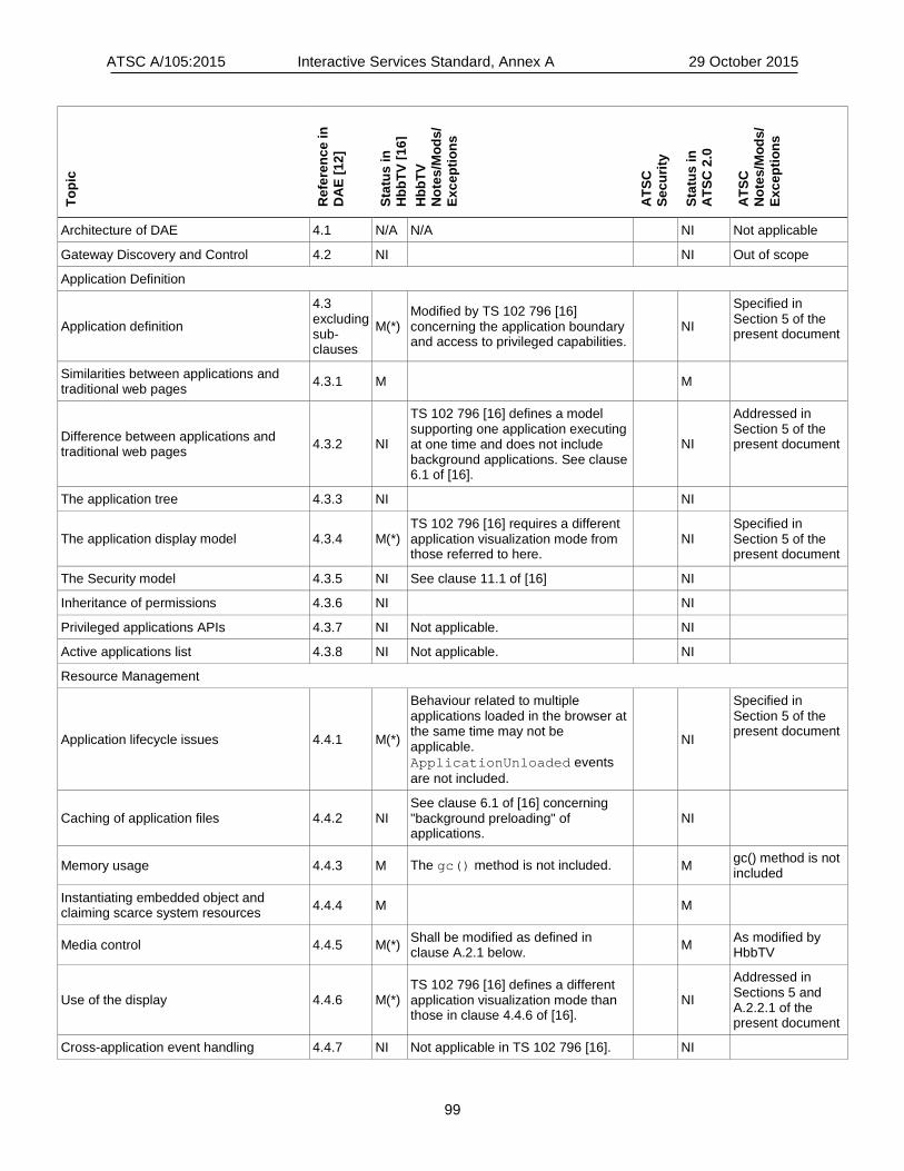
ATSC A/105:2015 Interactive Services Standard, Annex A 29 October 2015
99
Topi
c
Ref
eren
ce in
D
AE
[12]
Stat
us in
H
bbTV
[16]
H
bbTV
N
otes
/Mod
s/
Exce
ptio
ns
ATS
C
Secu
rity
Stat
us in
A
TSC
2.0
ATS
C
Not
es/M
ods/
Ex
cept
ions
Architecture of DAE 4.1 N/A N/A NI Not applicable
Gateway Discovery and Control 4.2 NI NI Out of scope
Application Definition
Application definition
4.3 excluding sub-clauses
M(*) Modified by TS 102 796 [16] concerning the application boundary and access to privileged capabilities.
NI
Specified in Section 5 of the present document
Similarities between applications and traditional web pages 4.3.1 M M
Difference between applications and traditional web pages 4.3.2 NI
TS 102 796 [16] defines a model supporting one application executing at one time and does not include background applications. See clause 6.1 of [16].
NI
Addressed in Section 5 of the present document
The application tree 4.3.3 NI NI
The application display model 4.3.4 M(*) TS 102 796 [16] requires a different application visualization mode from those referred to here.
NI Specified in Section 5 of the present document
The Security model 4.3.5 NI See clause 11.1 of [16] NI
Inheritance of permissions 4.3.6 NI NI
Privileged applications APIs 4.3.7 NI Not applicable. NI
Active applications list 4.3.8 NI Not applicable. NI
Resource Management
Application lifecycle issues 4.4.1 M(*)
Behaviour related to multiple applications loaded in the browser at the same time may not be applicable. ApplicationUnloaded events are not included.
NI
Specified in Section 5 of the present document
Caching of application files 4.4.2 NI See clause 6.1 of [16] concerning "background preloading" of applications.
NI
Memory usage 4.4.3 M The gc() method is not included. M gc() method is not included
Instantiating embedded object and claiming scarce system resources 4.4.4 M M
Media control 4.4.5 M(*) Shall be modified as defined in clause A.2.1 below. M As modified by
HbbTV
Use of the display 4.4.6 M(*) TS 102 796 [16] defines a different application visualization mode than those in clause 4.4.6 of [16].
NI
Addressed in Sections 5 and A.2.2.1 of the present document
Cross-application event handling 4.4.7 NI Not applicable in TS 102 796 [16]. NI

ATSC A/105:2015 Interactive Services Standard, Annex A 29 October 2015
100
Browser History 4.4.8 M(*) See clause A.2.6.4 of [16]. M As modified by HbbTV
Parental access control 4.5 M
- Approach A shall be supported for streaming on demand content. - Approach B shall be supported where CI+ is supported. - Approach C shall always be supported. See clause10.2.6 of [16].
NI
Specified in Section 10 of the current document
Content Download
Download manager 4.6.1 M-D(*)
The application/oipfStatusView embedded object is not included. S M-D As modified by
HbbTV
Content Access Download Descriptor 4.6.2 M-D S M-D(**)
As modified in Section A.2.1 of the present document
Triggering a download 4.6.3 M-D S M-D
Download protocol(s) 4.6.4 M-D S M-D(**)
With addition of FLUTE support, as specified in as specified in Section 5.2 of A/103 [2].
Streaming CoD
Unicast streaming 4.7.1 M(*)
Method 2 using an HTTP URL shall be supported. Method 3 shall be supported if the DRM feature is supported. Otherwise not included.
NI Refer to DASH profile in A/107 [23]
Multicast streaming 4.7.2 NI NI
Scheduled Content
Conveyance of channel list 4.8.1 M(*) Clause 4.8.1.2 of [12] is optional in DAE and not included in [16]. S M
Conveyance of channel list and list of scheduled recordings 4.8.2 M-P S M-P
Display Model 4.9 M M(**)
As modified by graphic plane model in Section A.3.2 of the present document.
Application Lifecycle
Web applications 5.1.1.2 M Web applications are equivalent to broadcast-independent applications in TS 102 796 [16].
NI Addressed in Section 5 of the present document
Using the Application.createApplication API call
5.1.1.3 M See clauses 6.2.6 and 9.2 of [16]. NI Specified in Section 5 of the present document
CE-HTML third party notifications 5.1.1.4 NI NI Specified in Section 11 of the present document
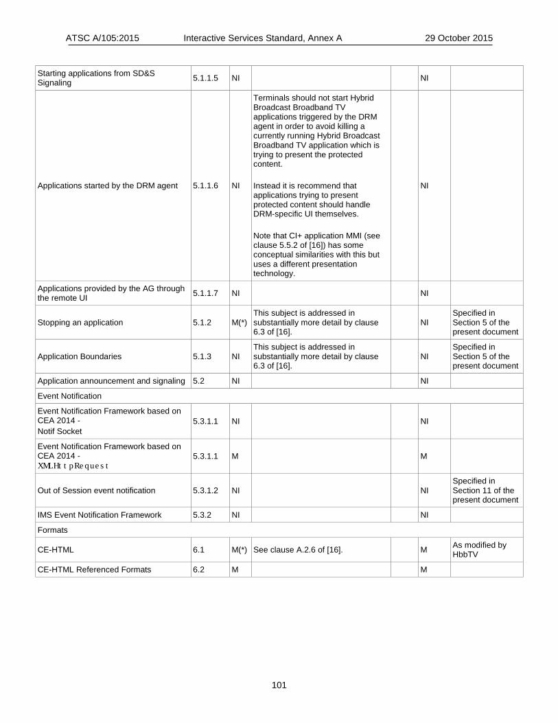
ATSC A/105:2015 Interactive Services Standard, Annex A 29 October 2015
101
Starting applications from SD&S Signaling 5.1.1.5 NI NI
Applications started by the DRM agent 5.1.1.6 NI
Terminals should not start Hybrid Broadcast Broadband TV applications triggered by the DRM agent in order to avoid killing a currently running Hybrid Broadcast Broadband TV application which is trying to present the protected content. Instead it is recommend that applications trying to present protected content should handle DRM-specific UI themselves. Note that CI+ application MMI (see clause 5.5.2 of [16]) has some conceptual similarities with this but uses a different presentation technology.
NI
Applications provided by the AG through the remote UI 5.1.1.7 NI NI
Stopping an application 5.1.2 M(*) This subject is addressed in substantially more detail by clause 6.3 of [16].
NI Specified in Section 5 of the present document
Application Boundaries 5.1.3 NI This subject is addressed in substantially more detail by clause 6.3 of [16].
NI Specified in Section 5 of the present document
Application announcement and signaling 5.2 NI NI
Event Notification
Event Notification Framework based on CEA 2014 - Notif Socket
5.3.1.1 NI NI
Event Notification Framework based on CEA 2014 - XMLHttpRequest
5.3.1.1 M M
Out of Session event notification 5.3.1.2 NI NI Specified in Section 11 of the present document
IMS Event Notification Framework 5.3.2 NI NI
Formats
CE-HTML 6.1 M(*) See clause A.2.6 of [16]. M As modified by HbbTV
CE-HTML Referenced Formats 6.2 M M
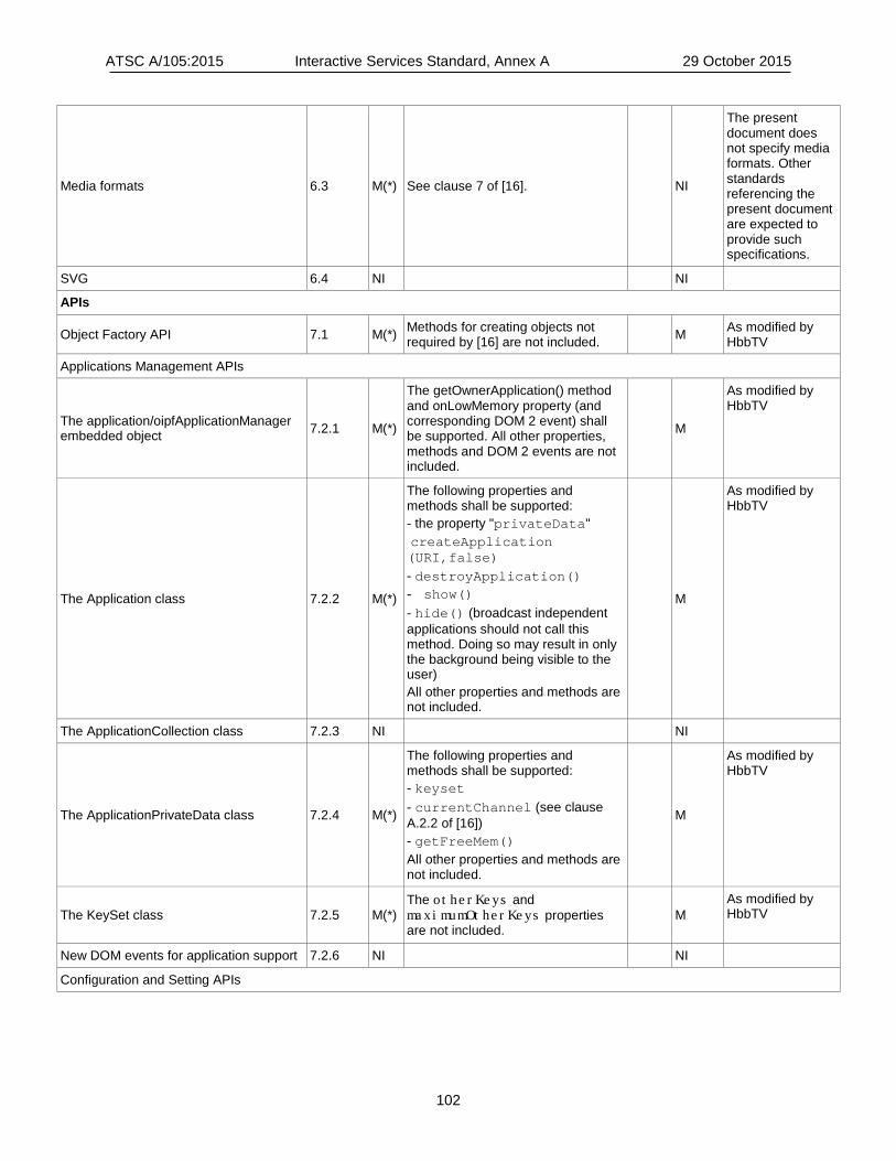
ATSC A/105:2015 Interactive Services Standard, Annex A 29 October 2015
102
Media formats 6.3 M(*) See clause 7 of [16]. NI
The present document does not specify media formats. Other standards referencing the present document are expected to provide such specifications.
SVG 6.4 NI NI
APIs
Object Factory API 7.1 M(*) Methods for creating objects not required by [16] are not included. M As modified by
HbbTV
Applications Management APIs
The application/oipfApplicationManager embedded object 7.2.1 M(*)
The getOwnerApplication() method and onLowMemory property (and corresponding DOM 2 event) shall be supported. All other properties, methods and DOM 2 events are not included.
M
As modified by HbbTV
The Application class 7.2.2 M(*)
The following properties and methods shall be supported: - the property "privateData" createApplication (URI,false) - destroyApplication() - show() - hide() (broadcast independent applications should not call this method. Doing so may result in only the background being visible to the user) All other properties and methods are not included.
M
As modified by HbbTV
The ApplicationCollection class 7.2.3 NI NI
The ApplicationPrivateData class 7.2.4 M(*)
The following properties and methods shall be supported: - keyset - currentChannel (see clause A.2.2 of [16]) - getFreeMem() All other properties and methods are not included.
M
As modified by HbbTV
The KeySet class 7.2.5 M(*) The otherKeys and maximumOtherKeys properties are not included.
M As modified by HbbTV
New DOM events for application support 7.2.6 NI NI
Configuration and Setting APIs
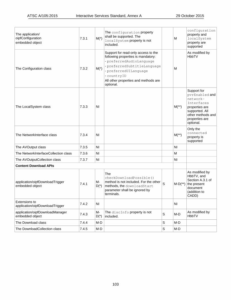
ATSC A/105:2015 Interactive Services Standard, Annex A 29 October 2015
103
The application/ oipfConfiguration embedded object
7.3.1 M(*)
The configuration property shall be supported. The localSystem property is not included.
M
configuration property and localSystem property are supported
The Configuration class 7.3.2 M(*)
Support for read-only access to the following properties is mandatory: - preferredAudioLanguage - preferredSubtitleLanguage - preferredUILanguage - countryID All other properties and methods are optional.
M
As modified by HbbTV
The LocalSystem class 7.3.3 NI M(**)
Support for pvrEnabled and network-Interfaces properties are supported. All other methods and properties are optional.
The NetworkInterface class 7.3.4 NI M(**)
Only the connected property is supported
The AVOutput class 7.3.5 NI NI
The NetworkInterfaceCollection class 7.3.6 NI M
The AVOutputCollection class 7.3.7 NI NI
Content Download APIs
application/oipfDownloadTrigger embedded object 7.4.1 M-
D(*)
The checkDownloadPossible() method is not included. For the other methods, the downloadStart parameter shall be ignored by terminals.
S M-D(**)
As modified by HbbTV, and Section A.3.1 of the present document (addition to CADD)
Extensions to application/oipfDownloadTrigger 7.4.2 NI NI
application/oipfDownloadManager embedded object 7.4.3 M-
D(*) The discInfo property is not included. S M-D As modified by
HbbTV
The Download class 7.4.4 M-D S M-D
The DownloadCollection class 7.4.5 M-D S M-D
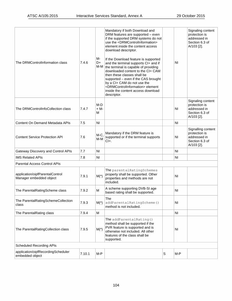
ATSC A/105:2015 Interactive Services Standard, Annex A 29 October 2015
104
The DRMControlInformation class 7.4.6 M-D+ M-M
Mandatory if both Download and DRM features are supported – even if the supported DRM systems do not use the <DRMControlInformation> element inside the content access download descriptor. If the Download feature is supported and the terminal supports CI+ and if the terminal is capable of providing downloaded content to the CI+ CAM then these classes shall be supported – even if the CAS brought by a CI+ CAM do not use the <DRMControlInformation> element inside the content access download descriptor.
NI
Signaling content protection is addressed in Section 6.3 of A/103 [2].
The DRMControlInfoCollection class 7.4.7 M-D + M-M
NI
Signaling content protection is addressed in Section 6.3 of A/103 [2].
Content On Demand Metadata APIs 7.5 NI NI
Content Service Protection API 7.6 M-C, M-M
Mandatory if the DRM feature is supported or if the terminal supports CI+.
NI
Signalling content protection is addressed in Section 6.3 of A/103 [2].
Gateway Discovery and Control APIs 7.7 NI NI
IMS Related APIs 7.8 NI NI
Parental Access Control APIs
application/oipfParentalControl Manager embedded object 7.9.1 M(*)
The parentalRatingSchemes property shall be supported. Other properties and methods are not included.
NI
The ParentalRatingScheme class 7.9.2 M A scheme supporting DVB-SI age based rating shall be supported. NI
The ParentalRatingSchemeCollection class 7.9.3 M(*)
The addParentalRatingScheme() method is not included.
NI
The ParentalRating class 7.9.4 M NI
The ParentalRatingCollection class 7.9.5 M(*)
The addParentalRating() method shall be supported if the PVR feature is supported and is otherwise not included. All other features of the class shall be supported.
NI
Scheduled Recording APIs
application/oipfRecordingScheduler embedded object 7.10.1 M-P S M-P

ATSC A/105:2015 Interactive Services Standard, Annex A 29 October 2015
105
The ScheduledRecording class 7.10.2 M-P(*)
"Only the following properties shall be supported: - startPadding - endPadding - name - description - startTime - duration - parentalRatings - channel All other properties are not included. The parentalRating property has been renamed to parentalRatings in errata 2 to the OPIF DAE specification [12].
S M-P(**)
As modified by HbbTV, except Section 10 of the present document for parental ratings.
The ScheduledRecordingCollection class 7.10.3 M-P S M-P
Extension to application/oipfRecordingScheduler for control of recordings
7.10.4 M-P(*)
The recordings property shall be supported. Other properties and methods are not included.
S M-P As modified by HbbTV
The Recording class 7.10.5 M-P(*)
The following properties shall be supported: - state - id - recordingStartTime - recordingDuration Since the Recording class implements the ScheduledRecording interface, the properties required to be supported from that interface as defined above are also required. All other properties are not included.
S M-P
As modified by HbbTV
The RecordingCollection class 7.10.6 M-P S M-P
The PVREvent class 7.10.7 NI NI
The Bookmark class 7.10.8 NI NI
The BookMarkCollection class 7.10.9 NI NI
Remote Management APIs 7.11 NI NI
Metadata APIs
The application/oipfSearchManager embedded object
7.12.1 as modified by clause A.2.9.1 of [16].
M(*) The guideDaysAvailable and onMetadataUpdate properties are not included. For the createSearch method, only the value '1' of the searchTarget parameter is included. For the function “onMetadataSearch”, the value “2” for the state property is not supported.
NI
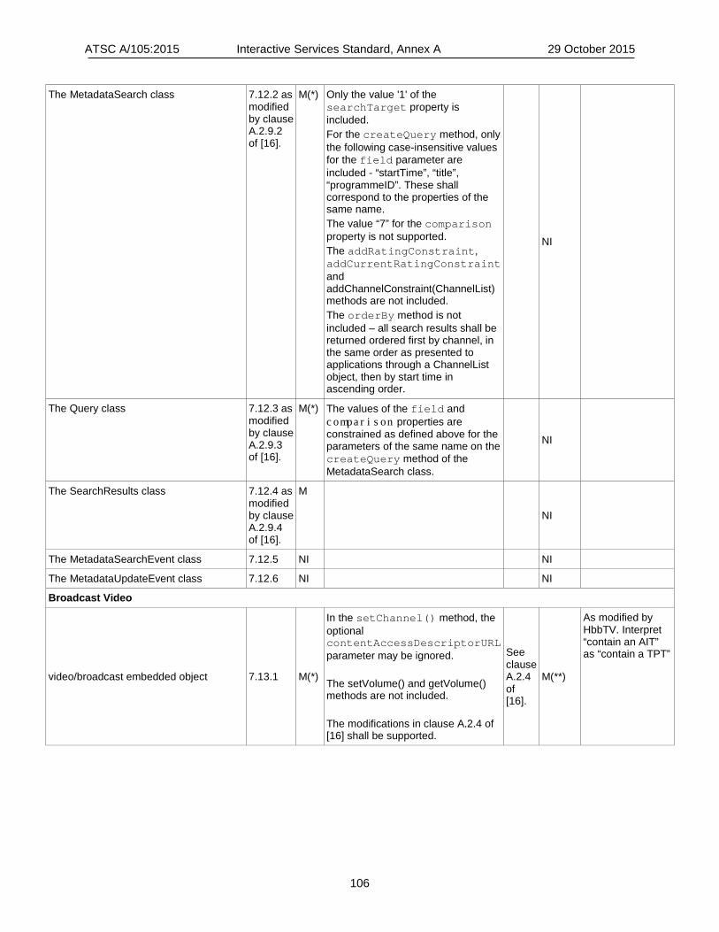
ATSC A/105:2015 Interactive Services Standard, Annex A 29 October 2015
106
The MetadataSearch class 7.12.2 as modified by clause A.2.9.2 of [16].
M(*) Only the value '1' of the searchTarget property is included. For the createQuery method, only the following case-insensitive values for the field parameter are included - “startTime”, “title”, “programmeID”. These shall correspond to the properties of the same name. The value “7” for the comparison property is not supported. The addRatingConstraint, addCurrentRatingConstraint and addChannelConstraint(ChannelList) methods are not included. The orderBy method is not included – all search results shall be returned ordered first by channel, in the same order as presented to applications through a ChannelList object, then by start time in ascending order.
NI
The Query class 7.12.3 as modified by clause A.2.9.3 of [16].
M(*) The values of the field and comparison properties are constrained as defined above for the parameters of the same name on the createQuery method of the MetadataSearch class.
NI
The SearchResults class 7.12.4 as modified by clause A.2.9.4 of [16].
M
NI
The MetadataSearchEvent class 7.12.5 NI NI
The MetadataUpdateEvent class 7.12.6 NI NI
Broadcast Video
video/broadcast embedded object 7.13.1 M(*)
In the setChannel() method, the optional contentAccessDescriptorURL parameter may be ignored. The setVolume() and getVolume() methods are not included. The modifications in clause A.2.4 of [16] shall be supported.
See clause A.2.4 of [16].
M(**)
As modified by HbbTV. Interpret “contain an AIT” as “contain a TPT”
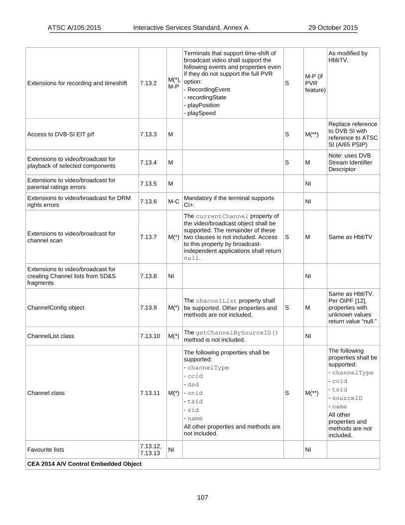
ATSC A/105:2015 Interactive Services Standard, Annex A 29 October 2015
107
Extensions for recording and timeshift 7.13.2 M(*), M-P
Terminals that support time-shift of broadcast video shall support the following events and properties even if they do not support the full PVR option: - RecordingEvent - recordingState - playPosition - playSpeed
S M-P (if PVR feature)
As modified by HbbTV.
Access to DVB-SI EIT p/f 7.13.3 M S M(**)
Replace reference to DVB SI with reference to ATSC SI (A/65 PSIP)
Extensions to video/broadcast for playback of selected components 7.13.4 M S M
Note: uses DVB Stream Identifier Descriptor
Extensions to video/broadcast for parental ratings errors 7.13.5 M NI
Extensions to video/broadcast for DRM rights errors 7.13.6 M-C Mandatory if the terminal supports
CI+. NI
Extensions to video/broadcast for channel scan 7.13.7 M(*)
The currentChannel property of the video/broadcast object shall be supported. The remainder of these two clauses is not included. Access to this property by broadcast-independent applications shall return null.
S M Same as HbbTV
Extensions to video/broadcast for creating Channel lists from SD&S fragments
7.13.8 NI NI
ChannelConfig object 7.13.9 M(*) The channelList property shall be supported. Other properties and methods are not included.
S M
Same as HbbTV. Per OIPF [12], properties with unknown values return value “null.”
ChannelList class 7.13.10 M(*) The getChannelBySourceID() method is not included. NI
Channel class 7.13.11 M(*)
The following properties shall be supported: - channelType - ccid - dsd - onid - tsid - sid - name All other properties and methods are not included.
S M(**)
The following properties shall be supported: - channelType - ccid - tsid - sourceID - name All other properties and methods are not included.
Favourite lists 7.13.12, 7.13.13 NI NI
CEA 2014 A/V Control Embedded Object
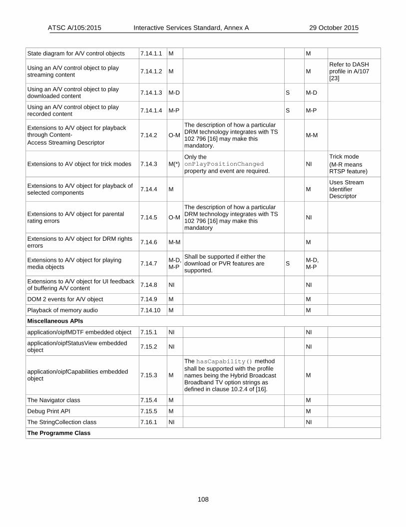
ATSC A/105:2015 Interactive Services Standard, Annex A 29 October 2015
108
State diagram for A/V control objects 7.14.1.1 M M
Using an A/V control object to play streaming content 7.14.1.2 M M
Refer to DASH profile in A/107 [23]
Using an A/V control object to play downloaded content 7.14.1.3 M-D S M-D
Using an A/V control object to play recorded content 7.14.1.4 M-P S M-P
Extensions to A/V object for playback through Content- Access Streaming Descriptor
7.14.2 O-M
The description of how a particular DRM technology integrates with TS 102 796 [16] may make this mandatory.
M-M
Extensions to AV object for trick modes 7.14.3 M(*) Only the onPlayPositionChanged property and event are required.
NI Trick mode (M-R means RTSP feature)
Extensions to A/V object for playback of selected components 7.14.4 M M
Uses Stream Identifier Descriptor
Extensions to A/V object for parental rating errors 7.14.5 O-M
The description of how a particular DRM technology integrates with TS 102 796 [16] may make this mandatory
NI
Extensions to A/V object for DRM rights errors 7.14.6 M-M M
Extensions to A/V object for playing media objects 7.14.7 M-D,
M-P
Shall be supported if either the download or PVR features are supported.
S M-D, M-P
Extensions to A/V object for UI feedback of buffering A/V content 7.14.8 NI NI
DOM 2 events for A/V object 7.14.9 M M
Playback of memory audio 7.14.10 M M
Miscellaneous APIs
application/oipfMDTF embedded object 7.15.1 NI NI
application/oipfStatusView embedded object 7.15.2 NI NI
application/oipfCapabilities embedded object 7.15.3 M
The hasCapability() method shall be supported with the profile names being the Hybrid Broadcast Broadband TV option strings as defined in clause 10.2.4 of [16].
M
The Navigator class 7.15.4 M M
Debug Print API 7.15.5 M M
The StringCollection class 7.16.1 NI NI
The Programme Class
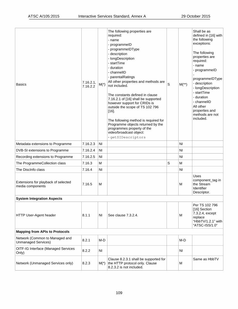
ATSC A/105:2015 Interactive Services Standard, Annex A 29 October 2015
109
Basics 7.16.2.1, 7.16.2.2 M(*)
The following properties are required: - name - programmeID - programmeIDType - description - longDescription - startTime - duration - channelID - parentalRatings All other properties and methods are not included. The constants defined in clause 7.16.2.1 of [16] shall be supported however support for CRIDs is outside the scope of TS 102 796 [16]. The following method is required for Programme objects returned by the programmes property of the video/broadcast object: - getSIDescriptors
S M(**)
Shall be as defined in [16] with the following exceptions: The following properties are required: - name - programmeID - programmeIDType - description - longDescription - startTime - duration - channelID All other properties and methods are not included.
Metadata extensions to Programme 7.16.2.3 NI NI
DVB-SI extensions to Programme 7.16.2.4 NI NI
Recording extensions to Programme 7.16.2.5 NI NI
The ProgrammeCollection class 7.16.3 M S M
The DiscInfo class 7.16.4 NI NI
Extensions for playback of selected media components 7.16.5 M M
Uses component_tag in the Stream Identifier Descriptor.
System Integration Aspects
HTTP User-Agent header 8.1.1 NI See clause 7.3.2.4.
M
Per TS 102 796 [16] Section 7.3.2.4, except replace “HbbTV/1.2.1” with “ATSC-ISS/1.0”
Mapping from APIs to Protocols
Network (Common to Managed and Unmanaged Services) 8.2.1 M-D M-D
OITF-IG Interface (Managed Services Only) 8.2.2 NI NI
Network (Unmanaged Services only) 8.2.3 M(*) Clause 8.2.3.1 shall be supported for the HTTP protocol only. Clause 8.2.3.2 is not included.
M Same as HbbTV
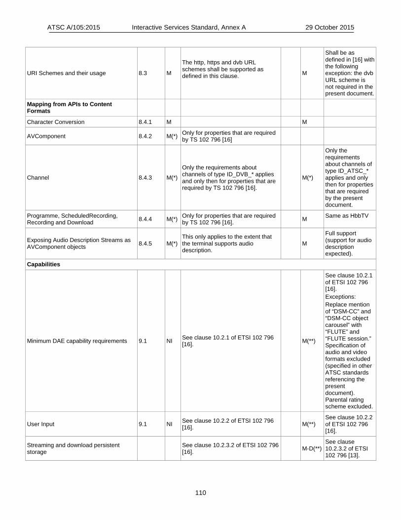
ATSC A/105:2015 Interactive Services Standard, Annex A 29 October 2015
110
URI Schemes and their usage 8.3 M
The http, https and dvb URL schemes shall be supported as defined in this clause.
M
Shall be as defined in [16] with the following exception: the dvb URL scheme is not required in the present document.
Mapping from APIs to Content Formats
Character Conversion 8.4.1 M M
AVComponent 8.4.2 M(*) Only for properties that are required by TS 102 796 [16]
Channel 8.4.3 M(*)
Only the requirements about channels of type ID_DVB_* applies and only then for properties that are required by TS 102 796 [16].
M(*)
Only the requirements about channels of type ID_ATSC_* applies and only then for properties that are required by the present document.
Programme, ScheduledRecording, Recording and Download 8.4.4 M(*) Only for properties that are required
by TS 102 796 [16]. M Same as HbbTV
Exposing Audio Description Streams as AVComponent objects 8.4.5 M(*)
This only applies to the extent that the terminal supports audio description.
M
Full support (support for audio description expected).
Capabilities
Minimum DAE capability requirements 9.1 NI See clause 10.2.1 of ETSI 102 796 [16]. M(**)
See clause 10.2.1 of ETSI 102 796 [16]. Exceptions: Replace mention of “DSM-CC” and “DSM-CC object carousel” with “FLUTE” and “FLUTE session.” Specification of audio and video formats excluded (specified in other ATSC standards referencing the present document). Parental rating scheme excluded.
User Input 9.1 NI See clause 10.2.2 of ETSI 102 796 [16]. M(**)
See clause 10.2.2 of ETSI 102 796 [16].
Streaming and download persistent storage See clause 10.2.3.2 of ETSI 102 796
[16]. M-D(**) See clause 10.2.3.2 of ETSI 102 796 [13].

ATSC A/105:2015 Interactive Services Standard, Annex A 29 October 2015
111
PVR API execution See clause 10.2.3.3 of ETSI 102 796 [16]. M-P(**)
See clause 10.2.3.3 of ETSI 102 796 [13].
HbbTV capabilities and options strings See clause 10.2.4 of ETSI 102 796 [16]. M(**)
Per HbbTV, except the capabilities string fragment shall include “+ATSC_T” UI profile name fragment (extending Table 15 of OIPF DAE [11]).
Terminal memory requirements See clause 10.2.5 of ETSI 102 796 [16]. M(**)
Specific requirement is TBD. Information to guide implementers can be found in Section 10.2.5 of ETSI 102 796 [16].
SSL/TLS Requirements 9.1.1 M(*) 9.1.1.1 and 9.1.1.2 are required. 9.1.1.3 is replaced by clause 11.2 of [16].
M See A/106 [22] Section 5
Default UI profiles 9.2 NI NI
CEA-2014 Capability Negotiation and Extensions
Tuner/broadcast capability indication 9.3.1 M M
Broadcasted content over IP capability indication 9.3.2 NI NI
PVR capability indication 9.3.3 M-P M-P
Download Cod capability indication 9.3.4 M-D M-D
Parental ratings 9.3.5 M NI ATSC 2.0 has a different parental rating scheme
Extended A/V API support 9.3.6 M M
OITF Metadata API support 9.3.7 M M
OITF Configuration API support 9.3.8 M M
IMS API Support 9.3.9 NI NI
DRM capability indication 9.3.10 M M
Media profile capability indication 9.3.11 M M
Remote diagnostics support 9.3.12 NI NI
SVG 9.3.13 NI NI
Third party notification support 9.3.14 NI M
Third party notifications supported in ATSC 2.0
Multicast Delivery Terminating Function support 9.3.15 NI NI
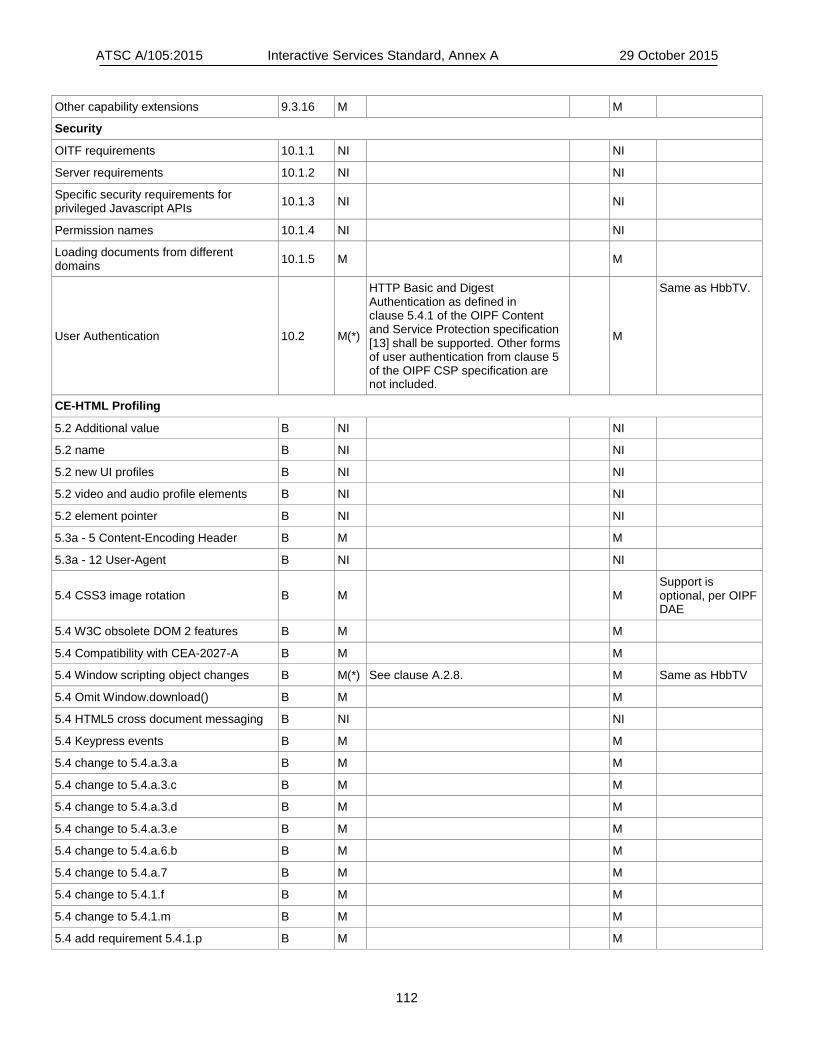
ATSC A/105:2015 Interactive Services Standard, Annex A 29 October 2015
112
Other capability extensions 9.3.16 M M
Security
OITF requirements 10.1.1 NI NI
Server requirements 10.1.2 NI NI
Specific security requirements for privileged Javascript APIs 10.1.3 NI NI
Permission names 10.1.4 NI NI
Loading documents from different domains 10.1.5 M M
User Authentication 10.2 M(*)
HTTP Basic and Digest Authentication as defined in clause 5.4.1 of the OIPF Content and Service Protection specification [13] shall be supported. Other forms of user authentication from clause 5 of the OIPF CSP specification are not included.
M
Same as HbbTV.
CE-HTML Profiling
5.2 Additional value B NI NI
5.2 name B NI NI
5.2 new UI profiles B NI NI
5.2 video and audio profile elements B NI NI
5.2 element pointer B NI NI
5.3a - 5 Content-Encoding Header B M M
5.3a - 12 User-Agent B NI NI
5.4 CSS3 image rotation B M M Support is optional, per OIPF DAE
5.4 W3C obsolete DOM 2 features B M M
5.4 Compatibility with CEA-2027-A B M M
5.4 Window scripting object changes B M(*) See clause A.2.8. M Same as HbbTV
5.4 Omit Window.download() B M M
5.4 HTML5 cross document messaging B NI NI
5.4 Keypress events B M M
5.4 change to 5.4.a.3.a B M M
5.4 change to 5.4.a.3.c B M M
5.4 change to 5.4.a.3.d B M M
5.4 change to 5.4.a.3.e B M M
5.4 change to 5.4.a.6.b B M M
5.4 change to 5.4.a.7 B M M
5.4 change to 5.4.1.f B M M
5.4 change to 5.4.1.m B M M
5.4 add requirement 5.4.1.p B M M
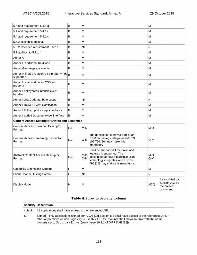
ATSC A/105:2015 Interactive Services Standard, Annex A 29 October 2015
113
5.4 add requirement 5.4.1.q B M M
5.4 add requirement 5.4.1.r B M M
5.4 add requirement 5.4.1.s B M M
5.6.2 section is optional B M M
5.6.2 extended requirement 5.6.2.a B NI NI
5.7 addition to 5.7.1.f B M M
Annex C B M M
Annex F additional KeyCode B M . M
Annex G onkeypress events B M M
Annex H image rotation CSS property not supported B M M
Annex H clarification for CSS font property B M M
Annex I onkeypress intrinsic event handler B M M
Annex I charCode attribute support B NI NI
Annex I DOM 2 Event clarification B M M
Annex I Full support except interfaces B M M
Annex I added DocumentView interface B M M
Content Access Descriptor Syntax and Semantics
Content Access Download Descriptor Format E.1 M-D M-D
Content Access Streaming Descriptor Format E.2 O-M
The description of how a particular DRM technology integrates with TS 102 796 [16] may make this mandatory
O-M
Abstract Content Access Descriptor Format E.3 M-D,
O-M
Shall be supported if the download features is supported. The description of how a particular DRM technology integrates with TS 102 796 [16] may make this mandatory.
M-D O-M
Capability Extensions Schema F M M
Client Channel Listing Format G NI NI
Display Model H M M(**)
As modified by Section A.3.2 of the present document.
Table A.2 Key to Security Column
Security Description
<blank> All applications shall have access to the referenced API.
S Signed – only applications signed per A/106 [22] Section 5.3 shall have access to the referenced API. If other applications or web pages try to use this API, the terminal shall throw an error with the name property set to SecurityError (see clause 10.1.1 of OIPF DAE [12]).
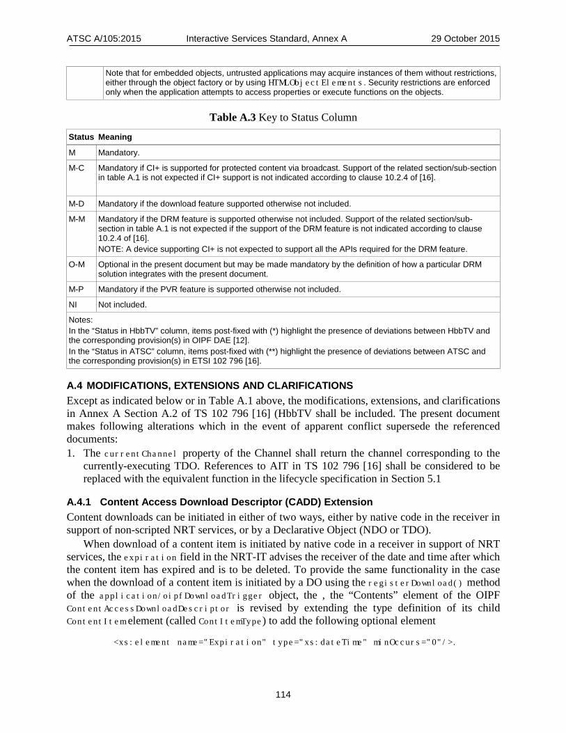
ATSC A/105:2015 Interactive Services Standard, Annex A 29 October 2015
114
Note that for embedded objects, untrusted applications may acquire instances of them without restrictions, either through the object factory or by using HTMLObjectElements. Security restrictions are enforced only when the application attempts to access properties or execute functions on the objects.
Table A.3 Key to Status Column
Status Meaning
M Mandatory. M-C Mandatory if CI+ is supported for protected content via broadcast. Support of the related section/sub-section
in table A.1 is not expected if CI+ support is not indicated according to clause 10.2.4 of [16].
M-D Mandatory if the download feature supported otherwise not included.
M-M Mandatory if the DRM feature is supported otherwise not included. Support of the related section/sub-section in table A.1 is not expected if the support of the DRM feature is not indicated according to clause 10.2.4 of [16]. NOTE: A device supporting CI+ is not expected to support all the APIs required for the DRM feature.
O-M Optional in the present document but may be made mandatory by the definition of how a particular DRM solution integrates with the present document.
M-P Mandatory if the PVR feature is supported otherwise not included.
NI Not included.
Notes: In the “Status in HbbTV” column, items post-fixed with (*) highlight the presence of deviations between HbbTV and the corresponding provision(s) in OIPF DAE [12]. In the “Status in ATSC” column, items post-fixed with (**) highlight the presence of deviations between ATSC and the corresponding provision(s) in ETSI 102 796 [16].
A.4 MODIFICATIONS, EXTENSIONS AND CLARIFICATIONS Except as indicated below or in Table A.1 above, the modifications, extensions, and clarifications in Annex A Section A.2 of TS 102 796 [16] (HbbTV shall be included. The present document makes following alterations which in the event of apparent conflict supersede the referenced documents: 1. The currentChannel property of the Channel shall return the channel corresponding to the
currently-executing TDO. References to AIT in TS 102 796 [16] shall be considered to be replaced with the equivalent function in the lifecycle specification in Section 5.1
A.4.1 Content Access Download Descriptor (CADD) Extension Content downloads can be initiated in either of two ways, either by native code in the receiver in support of non-scripted NRT services, or by a Declarative Object (NDO or TDO).
When download of a content item is initiated by native code in a receiver in support of NRT services, the expiration field in the NRT-IT advises the receiver of the date and time after which the content item has expired and is to be deleted. To provide the same functionality in the case when the download of a content item is initiated by a DO using the registerDownload() method of the application/oipfDownloadTrigger object, the , the “Contents” element of the OIPF ContentAccessDownloadDescriptor is revised by extending the type definition of its child ContentItem element (called ContItemType) to add the following optional element
<xs:element name="Expiration" type="xs:dateTime" minOccurs="0"/>.

ATSC A/105:2015 Interactive Services Standard, Annex A 29 October 2015
115
An OIPF ContentAccessDownloadDescriptor consists of an XML document that has a Contents element as its root element. The Contents element contains a ContentItem child element of type ContItemType and unbounded cardinality. Each ContentItem instance represents a content item that is to be downloaded. The XML schema definition of the OIPF ContentAccessDownloadDescriptor is given in Annex E.3 of OIPF DAE [12].
The revised Contents element of the ContentAccessDownloadDescriptor specified in the present standard is informatively described in Table A.4 below.

ATSC A/105:2015 Interactive Services Standard, Annex A 29 October 2015
116
Table A.4 ContentAccessDownloadDescriptor Contents Element
Element/Attribute (with @) Cardinality Data Type Description and Value
Contents Content Access Download Descriptor
ContentItem 0..N ContItemType Content Item
ContItemType
Extension base="tns:ContItemType"
Expiration 0..1 dateTime Expiration date & time
Contents – This element is the root element in an ATSC ContentAccessDownloadDescriptor which is a description of the items to be downloaded in a content download request. This is a slight modification of the Contents element in an OIPF ContentAccessDownloadDescriptor.
ContentItem – A ContentItem child element of a Contents element shall represent an individual content item to be downloaded in a content download request. It is a slight modification of the OIPF ContentItem element.
ContItemType – This ContItemType is the XML type for a ContentItem element. tns:ContItemType – tns:ContItemType is the XML type of the OIPF ContentItem element. Expiration – When present, the Expiration child element of a ContentItem element shall be a
date after which the content item represented by the ContentItem element should be deleted from storage. The normative definition of this element appears in the XML schema with namespace
http://www.atsc.org/XMLSchemas/iss/iss-cadd-1
that is defined in an XML schema file accompanying this standard.
<xs:element name="Expiration" type="xs:dateTime" minOccurs="0"/>
With this element added, the mapping shown in Table A.5 below can be made between the elements and attributes of the ContItemType definition in the OIPF contentAccessDownloadDescriptor.xsd schema (CADD) and the fields of the NRT-IT, TFT and File Description Table (FDT) in A/103 [2].
Table A.5 Mapping between ContItemType and NRT Values
OIPF ContItemType Elements/Attributes ATSC NRT-IT/TFT/FDT Fields
Title NRT-IT content_name_text()
Synopsis TFT text_fragment()
ContentID NRT-IT Content Labeling Descriptor
ContentURL NRT-IT Internet Location Descriptor and FDT Content-Location attribute
IconURL NRT-IT Icon Descriptor
ParentalRating NRT-IT Content Advisory Descriptor
Expiration NRT-IT expiration
ContentURL.Duration NRT-IT playback_time_in_seconds
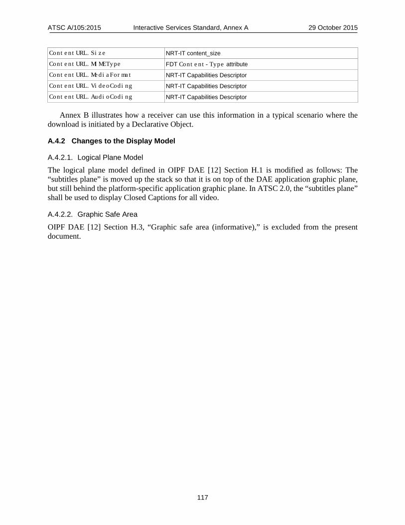
ATSC A/105:2015 Interactive Services Standard, Annex A 29 October 2015
117
ContentURL.Size NRT-IT content_size
ContentURL.MIMEType FDT Content-Type attribute ContentURL.MediaFormat NRT-IT Capabilities Descriptor
ContentURL.VideoCoding NRT-IT Capabilities Descriptor
ContentURL.AudioCoding NRT-IT Capabilities Descriptor
Annex B illustrates how a receiver can use this information in a typical scenario where the download is initiated by a Declarative Object.
A.4.2 Changes to the Display Model
A.4.2.1. Logical Plane Model
The logical plane model defined in OIPF DAE [12] Section H.1 is modified as follows: The “subtitles plane” is moved up the stack so that it is on top of the DAE application graphic plane, but still behind the platform-specific application graphic plane. In ATSC 2.0, the “subtitles plane” shall be used to display Closed Captions for all video.
A.4.2.2. Graphic Safe Area
OIPF DAE [12] Section H.3, “Graphic safe area (informative),” is excluded from the present document.
ATSC A/105:2015 Interactive Services Standard, Annex B 29 October 2015
118
Annex B: Use Cases for APIs
B.1 SCOPE Annex B describes a use case for the content download API.
B.2 USE CASE FOR CONTENT DOWNLOAD API Suppose a broadcaster wants to provide an Internet-based NRT service that has the functionality of a “Browse and Download” service, but uses an NRT Declarative Object (NDO) to provide a customized user interface. For example, this could be a “catch-up” service which allows users to download and view show episodes that they have missed. This could be done by offering an NRT with a “Push Scripted” consumption model. With such a service the NDO that provides the user interface would typically be maintained in receiver cache, so that it would start up immediately any time a user selects the service.
Since the NDO is providing a customized user interface, including menus and descriptions of content items available for viewing, and the NDO is initiating any content downloading over the Internet, there is no need for metadata about the viewable content items to appear in the NRT-IT. Instead, the NDO can just download metadata related to the content items over the Internet as needed.
Thus, the NDO would use a pre-defined URL to contact an Internet server and allow the user to navigate a customized catalog to select content items to download. When the user selects a content item, the NDO would retrieve the associated contentAccessDownloadDescriptor (CADD) from the server, and use the registerDownload() method of the application/oipfDownloadTrigger embedded object to initiate a download of the selected content item. The receiver’s native download manager can use the information in the CADD to check the content advisory rating (parental rating) of the content item, get the URL(s) needed for the download, find the total size of the content item so it can allocate buffer space efficiently, check the MIME type, media format and encodings of the components of the content item to ensure that it will be able to render it. It can also use the Expiration date and time to manage the life cycle of the content item:
1) During Download – If the download is going so slowly that the content item will expire before the download is complete, the download manager can cancel the download.
2) After Download – After the content item has been downloaded, the receiver can advise the user of the expiration date and time, so that the user can be sure to view it before it expires.
3) After Expiration – When the content item expires, the download manager can delete it to free up local storage space. If the user attempts to play it after it expires, the download manager can advise the user that it is no longer available for play out.
ATSC A/105:2015 Interactive Services Standard, Annex C 29 October 2015
119
Annex C: Activation Trigger Delivery by ACR Systems
C.1 SCOPE Annex C describes possible architectures for implementing Activation Trigger delivery by Automatic Content Recognition (ACR) systems in an ATSC broadcast environment. The intent is not to constrain actual implementations, but simply to demonstrate the feasibility of this form of Activation Trigger delivery.
C.2 INTRODUCTION AND ARCHITECTURE Section 14 of this document describes the architecture of ACR systems in an ATSC broadcast environment from a receiver’s standpoint. Some ACR systems include an ACR server, and some ACR systems do not. In fingerprinting ACR systems, receivers compute and send frame signatures to an ACR server, and the ACR server sends back the information needed by the receivers. Thus, fingerprinting ACR systems always include an ACR server. In watermarking ACR systems, the watermarks may contain only codes that uniquely identify the frames, or the watermarks may contain the full information needed by receivers. When the watermarks contain only codes, receivers must extract the codes and send them to an ACR server, and the ACR server sends back the information needed by the receivers. In the case when the watermarks include the full information, receivers can just extract the information they need directly from the watermarks, and no ACR server is needed.
In those ACR systems that include an ACR server, two different models are commonly used for communication between the ACR servers and receivers: a request/response model and an event-driven model.
In the request/response ACR server model the receiver is expected to compute signatures of, or extract codes from, the content periodically (e.g. every 5 seconds) and send requests containing the signatures or codes to an ACR server. When an ACR server gets a request from a receiver, it returns a response. The communications session is not kept open between request/response instances. In this model, it is not feasible for an ACR server to initiate messages to a receiver.
In the event driven ACR model the receiver is expected to initiate a persistent connection to the ACR server, compute signatures of, or extract codes from, frames periodically (e.g., every 5 seconds), and submit the signatures or codes over the connection. In this scenario the receiver includes a submission sequence number in the message with each submission. The ACR server does not respond to each submission. It sends a message to the receiver only when a new segment is detected or when an event activation needs to be communicated to the receiver. In this model, it is possible for the ACR server to initiate messages to the client at any time.
It is assumed in this annex that the broadcaster of the channel being processed is supporting the TDO interaction model.
There are two general type of event activations: static activations in which the activation time is known before the broadcast of the segment begins, and dynamic activations in which the activation time in determined dynamically as the segment is being broadcast. In pre-recorded segments all of the event activations are static. In segments that are broadcasting live shows, some
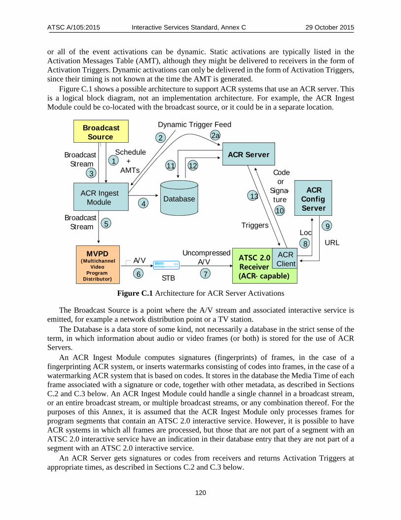
ATSC A/105:2015 Interactive Services Standard, Annex C 29 October 2015
120
or all of the event activations can be dynamic. Static activations are typically listed in the Activation Messages Table (AMT), although they might be delivered to receivers in the form of Activation Triggers. Dynamic activations can only be delivered in the form of Activation Triggers, since their timing is not known at the time the AMT is generated.
Figure C.1 shows a possible architecture to support ACR systems that use an ACR server. This is a logical block diagram, not an implementation architecture. For example, the ACR Ingest Module could be co-located with the broadcast source, or it could be in a separate location.
BroadcastSource
Triggers
MVPD(Multichannel
Video Program
Distributor)
ACR Server
A/V
Code or
Signa-ture
STB
UncompressedA/V ATSC 2.0
Receiver(ACR- capable)
ACRClient
ACR Ingest Module Database
ACR Config Server
Broadcast Stream
Broadcast Stream
Schedule+
AMTs
LocURL
3
2
4
6 7
1
8
9
10
11 12
13
Dynamic Trigger Feed
5
2a
Figure C.1 Architecture for ACR Server Activations
The Broadcast Source is a point where the A/V stream and associated interactive service is emitted, for example a network distribution point or a TV station.
The Database is a data store of some kind, not necessarily a database in the strict sense of the term, in which information about audio or video frames (or both) is stored for the use of ACR Servers.
An ACR Ingest Module computes signatures (fingerprints) of frames, in the case of a fingerprinting ACR system, or inserts watermarks consisting of codes into frames, in the case of a watermarking ACR system that is based on codes. It stores in the database the Media Time of each frame associated with a signature or code, together with other metadata, as described in Sections C.2 and C.3 below. An ACR Ingest Module could handle a single channel in a broadcast stream, or an entire broadcast stream, or multiple broadcast streams, or any combination thereof. For the purposes of this Annex, it is assumed that the ACR Ingest Module only processes frames for program segments that contain an ATSC 2.0 interactive service. However, it is possible to have ACR systems in which all frames are processed, but those that are not part of a segment with an ATSC 2.0 interactive service have an indication in their database entry that they are not part of a segment with an ATSC 2.0 interactive service.
An ACR Server gets signatures or codes from receivers and returns Activation Triggers at appropriate times, as described in Sections C.2 and C.3 below.

ATSC A/105:2015 Interactive Services Standard, Annex C 29 October 2015
121
The ACR Config Server just provides a way for ACR clients to determine the location of a suitable ACR Server. This discovery process could be achieved in other ways.
The ACR Client in an ATSC 2.0 capable receiver gets Activation Triggers from the ACR Server and passes them in to the main receiver code, using an API provided for that purpose. Normally the ACR client would be built into the receiver, but other configurations are possible.
A Multiprogram Video Program Distributor (MVPD) is typically a cable operator, satellite operator, or IPTV operator. It receives the broadcast stream from the Broadcast Source in some way, with the watermarks inserted by the ACR Ingest Module in the case of a watermarking ACR system, Such a system often strips out all the program elements other than audio and video tracks, and sends the resulting stream to set-top boxes (STBs) in customer premises.
A STB typically decodes (decompresses) the audio and video and sends them to a TV set for presentation to viewers. We are assuming in this Annex that DTV Closed Caption service #6, which contains ATSC 2.0 interactive service Triggers, is not available to the TV Set.
The architecture of an ACR system that uses direct delivery of information in watermarks would have no Database and no ACR Server. The ACR Ingest Module would insert information directly into the frames in the broadcast stream, in the form of watermarks, instead of inserting into a Database records that contain identifiers of frames and the information associated with them. Receivers would then extract this information from the frames in the broadcast, instead of getting it from an ACR server.
Section C.2 below considers delivery of Activation Triggers via request/response ACR servers, Section C.3 considers delivery of Activation Triggers via event driven ACR servers, and Section C.4 considers delivery of Activation Triggers directly in watermarks.
C.3 REQUEST/RESPONSE SERVER MODEL An ACR server that is using the request/response model and that is delivering Activation Triggers to DTV receivers can return the following responses:
• Null • Time Base Trigger • Activation Trigger A Null response means that the A/V programming is not recognized, or (in the case when the
ACR Ingest Module is computing signatures or inserting watermarks for all programming in the virtual channel, even for segments that have no interactive service associated with them) it means that the programming has no interactive service associated with it.
A Time Base Trigger response means that there is no activation near enough in time that the receiver needs to be told about it yet.
An Activation Trigger response means that an activation is due soon, and the terms in the Activation Trigger indicate the event to be activated and the Media Time when it is to be activated.
An efficient way to implement this ACR Server behavior is to follow the process described below, where the numbers of the actions in the process correspond to the numbers in the architecture diagram Figure C.1 above.
1) The broadcast schedule for the interactive service segments and the AMTs or their equivalents for each segment are delivered to the ACR Ingest Module ahead of the time the segments are broadcast. The broadcast schedule contains the segment ID, GPS start time and GPS end time of each segment that contains an interactive service associated with it. If there are any last-minute changes to the broadcast schedule, the ACR Ingest Module

ATSC A/105:2015 Interactive Services Standard, Annex C 29 October 2015
122
is notified of these changes immediately. The broadcast schedule could also contain the version number of the TPT for each segment, and the ACR Ingest Module could get notification in real time of any unscheduled changes in a TPT version, so that it can insert “version” (“v=”) terms into Triggers when needed. The Ingest Module could also be configured to insert “spread” (“s=”) terms into Triggers at suitable times, such as during a specified interval at the beginning of each segment (when many receivers are likely to be requesting new TPTs at the same time).
2) If there are any dynamic activations, links are set up from sources of dynamic activations to the ACR Ingest Module.
3) The broadcast stream is routed to the ACR Ingest Module. 4) The ACR Ingest Module extracts signatures from the frames (in the case of a fingerprint
ACR system) or inserts codes into the frames (in the case of a watermark ACR system), for all frames contained in segments that have an interactive service associated with them. (The ACR Ingest Module determines whether a frame is in such a segment by using a GPS clock and the start times and end times of segments in the broadcast schedule.) For each such frame the ACR Ingest Module inserts a record in the Database that includes a Trigger and the signature or code associated with the frame. The rules for what Trigger gets inserted are described at the end of this list of actions in the process.
5) Broadcast Stream continues on to the MVPD. 6) MVPD routes the Broadcast Stream to the STB at a subscriber’s location (typically
stripping out all of the interactive content first). 7) STB decodes the A/V and sends the uncompressed A/V to the DTV receiver. 8) When the receiver is first turned on, it sends its location to an ACR Configuration Server.
(The URL of the ACR Configuration Server is built into the receiver.) 9) The ACR Configuration Server sends back the URL of an ACR Server for the receiver to
use. 10) The ACR Client in the receiver starts extracting fingerprint signatures or watermark codes
and sending them to the ACR Server. 11) When the ACR Server receives a signature or code, it attempts to match it in the Database. 12) If the signature or code does not match any signature or code in the Database, then the
ACR Server gets back a “no match” indicator. If the signature or code does match a signature or code in the Database, then the ACR Server gets back the record for the frame that has the matching signature or code. In the latter case the record in the Database can contain a Time Base Trigger, and/or it can contain one or more Activation Triggers, depending on what was inserted into the record for the frame by the ACR Ingest Module.
13) If the ACR Server gets back a “no match” indicator from the Database, it returns a NULL response to the ACR Client. Otherwise the ACR Server returns to the ACR Client the Trigger or Triggers it obtained.
The following rules are used to determine what Trigger or Triggers the ACR Ingest Module inserts into each frame record in the Database.
It is assumed that there is some upper bound L1 on the length of the request intervals used by individual ACR clients in receivers. (It is not important whether the ACR clients know what this bound is, as long as they operate within it in practice.) Let L2 be the length of time it takes a typical ACR client to compute the signature or extract the watermark associated with a frame, counting from the time the frame arrives at the receiver. Let L3 be the typical round-trip time for a message
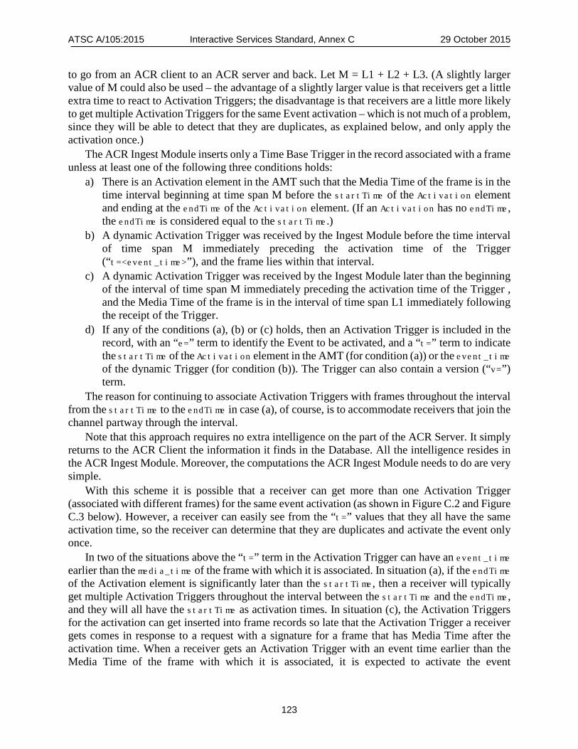
ATSC A/105:2015 Interactive Services Standard, Annex C 29 October 2015
123
to go from an ACR client to an ACR server and back. Let M = L1 + L2 + L3. (A slightly larger value of M could also be used – the advantage of a slightly larger value is that receivers get a little extra time to react to Activation Triggers; the disadvantage is that receivers are a little more likely to get multiple Activation Triggers for the same Event activation – which is not much of a problem, since they will be able to detect that they are duplicates, as explained below, and only apply the activation once.)
The ACR Ingest Module inserts only a Time Base Trigger in the record associated with a frame unless at least one of the following three conditions holds:
a) There is an Activation element in the AMT such that the Media Time of the frame is in the time interval beginning at time span M before the startTime of the Activation element and ending at the endTime of the Activation element. (If an Activation has no endTime, the endTime is considered equal to the startTime.)
b) A dynamic Activation Trigger was received by the Ingest Module before the time interval of time span M immediately preceding the activation time of the Trigger (“t=<event_time>”), and the frame lies within that interval.
c) A dynamic Activation Trigger was received by the Ingest Module later than the beginning of the interval of time span M immediately preceding the activation time of the Trigger , and the Media Time of the frame is in the interval of time span L1 immediately following the receipt of the Trigger.
d) If any of the conditions (a), (b) or (c) holds, then an Activation Trigger is included in the record, with an “e=” term to identify the Event to be activated, and a “t=” term to indicate the startTime of the Activation element in the AMT (for condition (a)) or the event_time of the dynamic Trigger (for condition (b)). The Trigger can also contain a version (“v=”) term.
The reason for continuing to associate Activation Triggers with frames throughout the interval from the startTime to the endTime in case (a), of course, is to accommodate receivers that join the channel partway through the interval.
Note that this approach requires no extra intelligence on the part of the ACR Server. It simply returns to the ACR Client the information it finds in the Database. All the intelligence resides in the ACR Ingest Module. Moreover, the computations the ACR Ingest Module needs to do are very simple.
With this scheme it is possible that a receiver can get more than one Activation Trigger (associated with different frames) for the same event activation (as shown in Figure C.2 and Figure C.3 below). However, a receiver can easily see from the “t=” values that they all have the same activation time, so the receiver can determine that they are duplicates and activate the event only once.
In two of the situations above the “t=” term in the Activation Trigger can have an event_time earlier than the media_time of the frame with which it is associated. In situation (a), if the endTime of the Activation element is significantly later than the startTime, then a receiver will typically get multiple Activation Triggers throughout the interval between the startTime and the endTime, and they will all have the startTime as activation times. In situation (c), the Activation Triggers for the activation can get inserted into frame records so late that the Activation Trigger a receiver gets comes in response to a request with a signature for a frame that has Media Time after the activation time. When a receiver gets an Activation Trigger with an event time earlier than the Media Time of the frame with which it is associated, it is expected to activate the event
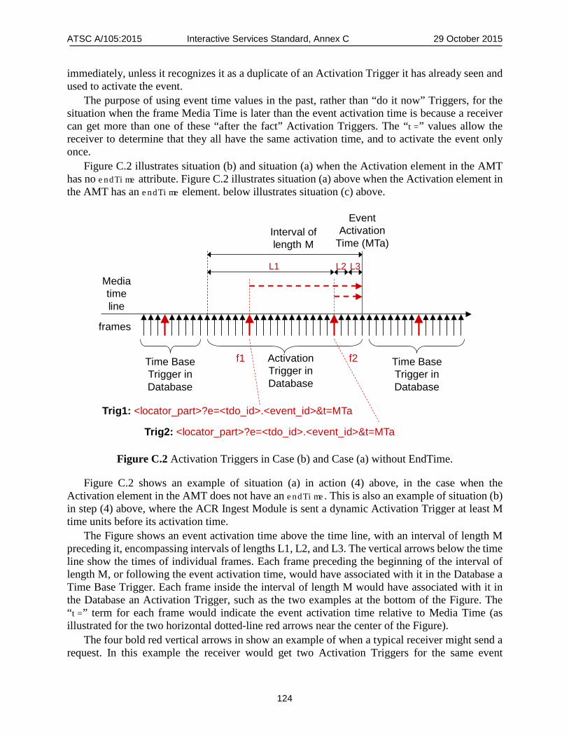
ATSC A/105:2015 Interactive Services Standard, Annex C 29 October 2015
124
immediately, unless it recognizes it as a duplicate of an Activation Trigger it has already seen and used to activate the event.
The purpose of using event time values in the past, rather than “do it now” Triggers, for the situation when the frame Media Time is later than the event activation time is because a receiver can get more than one of these “after the fact” Activation Triggers. The “t=” values allow the receiver to determine that they all have the same activation time, and to activate the event only once.
Figure C.2 illustrates situation (b) and situation (a) when the Activation element in the AMT has no endTime attribute. Figure C.2 illustrates situation (a) above when the Activation element in the AMT has an endTime element. below illustrates situation (c) above.
Figure C.2 Activation Triggers in Case (b) and Case (a) without EndTime.
Figure C.2 shows an example of situation (a) in action (4) above, in the case when the Activation element in the AMT does not have an endTime. This is also an example of situation (b) in step (4) above, where the ACR Ingest Module is sent a dynamic Activation Trigger at least M time units before its activation time.
The Figure shows an event activation time above the time line, with an interval of length M preceding it, encompassing intervals of lengths L1, L2, and L3. The vertical arrows below the time line show the times of individual frames. Each frame preceding the beginning of the interval of length M, or following the event activation time, would have associated with it in the Database a Time Base Trigger. Each frame inside the interval of length M would have associated with it in the Database an Activation Trigger, such as the two examples at the bottom of the Figure. The “t=” term for each frame would indicate the event activation time relative to Media Time (as illustrated for the two horizontal dotted-line red arrows near the center of the Figure).
The four bold red vertical arrows in show an example of when a typical receiver might send a request. In this example the receiver would get two Activation Triggers for the same event
Trig1: <locator_part>?e=<tdo_id>.<event_id>&t=MTa
EventActivation
Time (MTa)Interval of length M
frames
Time BaseTrigger in Database
Activation Trigger in Database
Trig2: <locator_part>?e=<tdo_id>.<event_id>&t=MTa
f1 f2
Mediatimeline
Time Base Trigger in Database
L1 L2 L3
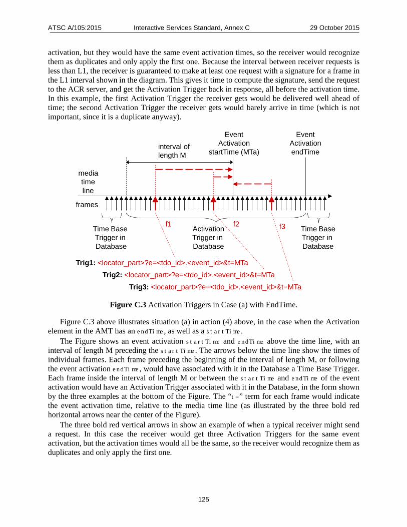
ATSC A/105:2015 Interactive Services Standard, Annex C 29 October 2015
125
activation, but they would have the same event activation times, so the receiver would recognize them as duplicates and only apply the first one. Because the interval between receiver requests is less than L1, the receiver is guaranteed to make at least one request with a signature for a frame in the L1 interval shown in the diagram. This gives it time to compute the signature, send the request to the ACR server, and get the Activation Trigger back in response, all before the activation time. In this example, the first Activation Trigger the receiver gets would be delivered well ahead of time; the second Activation Trigger the receiver gets would barely arrive in time (which is not important, since it is a duplicate anyway).
Figure C.3 Activation Triggers in Case (a) with EndTime.
Figure C.3 above illustrates situation (a) in action (4) above, in the case when the Activation element in the AMT has an endTime, as well as a startTime.
The Figure shows an event activation startTime and endTime above the time line, with an interval of length M preceding the startTime. The arrows below the time line show the times of individual frames. Each frame preceding the beginning of the interval of length M, or following the event activation endTime, would have associated with it in the Database a Time Base Trigger. Each frame inside the interval of length M or between the startTime and endTime of the event activation would have an Activation Trigger associated with it in the Database, in the form shown by the three examples at the bottom of the Figure. The “t=” term for each frame would indicate the event activation time, relative to the media time line (as illustrated by the three bold red horizontal arrows near the center of the Figure).
The three bold red vertical arrows in show an example of when a typical receiver might send a request. In this case the receiver would get three Activation Triggers for the same event activation, but the activation times would all be the same, so the receiver would recognize them as duplicates and only apply the first one.
Trig1: <locator_part>?e=<tdo_id>.<event_id>&t=MTa
EventActivation
startTime (MTa)
mediatimeline
interval of length M
frames
Time Base Trigger in Database
Time BaseTrigger in Database
ActivationTrigger in Database
Trig2: <locator_part>?e=<tdo_id>.<event_id>&t=MTa
f1 f2
EventActivationendTime
Trig3: <locator_part>?e=<tdo_id>.<event_id>&t=MTa
f3
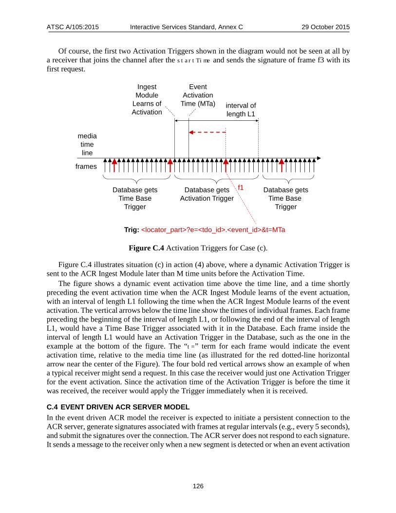
ATSC A/105:2015 Interactive Services Standard, Annex C 29 October 2015
126
Of course, the first two Activation Triggers shown in the diagram would not be seen at all by a receiver that joins the channel after the startTime and sends the signature of frame f3 with its first request.
Figure C.4 Activation Triggers for Case (c).
Figure C.4 illustrates situation (c) in action (4) above, where a dynamic Activation Trigger is sent to the ACR Ingest Module later than M time units before the Activation Time.
The figure shows a dynamic event activation time above the time line, and a time shortly preceding the event activation time when the ACR Ingest Module learns of the event actuation, with an interval of length L1 following the time when the ACR Ingest Module learns of the event activation. The vertical arrows below the time line show the times of individual frames. Each frame preceding the beginning of the interval of length L1, or following the end of the interval of length L1, would have a Time Base Trigger associated with it in the Database. Each frame inside the interval of length L1 would have an Activation Trigger in the Database, such as the one in the example at the bottom of the figure. The “t=” term for each frame would indicate the event activation time, relative to the media time line (as illustrated for the red dotted-line horizontal arrow near the center of the Figure). The four bold red vertical arrows show an example of when a typical receiver might send a request. In this case the receiver would just one Activation Trigger for the event activation. Since the activation time of the Activation Trigger is before the time it was received, the receiver would apply the Trigger immediately when it is received.
C.4 EVENT DRIVEN ACR SERVER MODEL In the event driven ACR model the receiver is expected to initiate a persistent connection to the ACR server, generate signatures associated with frames at regular intervals (e.g., every 5 seconds), and submit the signatures over the connection. The ACR server does not respond to each signature. It sends a message to the receiver only when a new segment is detected or when an event activation
Trig: <locator_part>?e=<tdo_id>.<event_id>&t=MTa
EventActivation
Time (MTa) interval of length L1
frames
Database getsTime Base
Trigger
Database getsTime Base
Trigger
Database getsActivation Trigger
Ingest Module
Learns ofActivation
mediatimeline
f1
ATSC A/105:2015 Interactive Services Standard, Annex C 29 October 2015
127
needs to be communicated to the receiver. In this model, it is possible for the ACR server to initiate messages to the client at any time over the persistent connection.
Moreover, it is straightforward for the server to maintain a certain amount of information about each receiver, such as the segment ID (locator_part of a Trigger) corresponding to the most recent submission from the receiver and the recent Activation Triggers sent to the receiver.
For an ACR server that is using this event driven model and is delivering activations to receivers, the following rules apply for messages from the ACR server:
• When the ACR server receives a signature from a receiver that corresponds to a frame in a new segment, the ACR server immediately sends a message to the receiver with a Time Base Trigger, to enable the receiver to obtain the associated TPT.
• When the ACR server receives a signature from a receiver that corresponds to a frame in a part of a segment that has a new version number for the TPT (different from the most recent version the receiver has seen), the ACR server immediately sends a message to the receiver with a Time Base Trigger that has a “v=” term to enable the receiver to obtain the new version of the associated TPT.
• When an event is due to be activated, the ACR server sends an Activation Trigger to the receiver. If possible, it sends the Activation Trigger slightly ahead of the time when the receiver needs to apply it, with a “t=” term in the Activation Trigger to indicate the activation time relative to the media time line. (This is very similar to the behavior in the request/response model.) If the ACR server learns of the activation so late that it cannot send an Activation Trigger as far ahead of time as usual, it sends an Activation Trigger as soon as it does learn of the activation. (In this latter case, the receiver could get the Activation Trigger after its activation time, in which case it is expected to activate the event as soon as it gets the Activation Trigger.)
The architecture for the Request/Response case shown in Figure C.1 is also suitable for this Event Driven case, with one difference. The difference is that for the Event Driven case there is a new action (2a). If there are any dynamic Activation Triggers, then connections are set up between the ACR Ingest Module and all ACR Servers that use the Database populated by the ACR Ingest Module, so that the ACR Ingest Module can send selected dynamic Activation Triggers to the ACR Servers.
The numbered actions for the Event Driven case are similar to those for the Request/Response case. Besides the new action (2a), action (4) is a little different, action (13) is a little different, and a new action (14) is added.
In action (4) the ACR Ingest Module extracts signatures from the frames (in the case of a fingerprint ACR system) or inserts codes into the frames (in the case of a watermark ACR system), for all frames contained in segments that have an interactive service associated with them. (The ACR Ingest Module determines whether a frame is in such a segment by using a GPS clock and the start times and end times of segments in the broadcast schedule.) For each such frame the ACR Ingest Module inserts a record in the Database that includes the signature or code associated with the frame and a Trigger. The Trigger included in the record by the ACR Ingest Module is a Time Base Trigger unless at least one of the following two conditions holds:
a) Same as condition (a) for the Request/Response ACR model. B) Same as condition (b) for the Request/Response ACR model. If either of the conditions (a) or (b) holds, then an Activation Trigger is included in the record,
with an “e=” term to identify the Event to be activated, and a “t=” term to indicate the startTime
ATSC A/105:2015 Interactive Services Standard, Annex C 29 October 2015
128
of the Activation element in the AMT (for condition (a)) or the event time of the dynamic Trigger (for condition (b)).
If a dynamic Activation Trigger is received by the Ingest Module during the interval of time span M immediately preceding the activation time of the Trigger (where M has the same meaning as in the request/response server case), then the Ingest Module passes the Activation Trigger on to all the ACR Servers that are using the Database into which the Ingest Module is inserting records, without putting anything in the Database concerning that dynamic Activation Trigger. (Variations on this architecture are possible in which dynamic Activation Triggers are passed directly from the dynamic Activation Trigger sources to the ACR servers without going through the Ingest Model, but the key idea is that the ACR servers must get the dynamic Activation Triggers that arrive later than M time units ahead of the activation time, so that it can send a message to the relevant receivers immediately. It might be too late if it waits until the next receiver submissions.)
In action (13), if the ACR Server gets back a “no match” indicator from the Database after not receiving one for the immediately preceding submission, it sends a NULL message to the receiver. If it gets back a Trigger with a locator_part that is different from the locator_part it got back for the immediately preceding submission, it sends the Trigger to the receiver, In both cases this tells the receiver that either the channel being viewed has been changed, or the segment being viewed has come to an end, so the receiver can terminate any TDO that is currently executing, and if necessary download a new TPT. If the ACR Server gets back one or more Activation Triggers, it sends them to the receiver, discarding any that are duplicates of Activation Triggers it has already sent to the receiver. Otherwise the ACR Server does nothing.
In a new action (14), if an ACR Server receives a dynamic Activation Trigger, it compares the locator_part of the dynamic Activation Trigger with the current locator_part for each of its ACR clients (where the current locator_part for a client is the locator_part of the Trigger that the ACR Server got from the Database for the most recent submission from the ACR client. For each client where the locator_part matches, the ACR Server sends the Activation Trigger to the client.
Figure C.2 and Figure C.3 show the handling of Triggers for static activations and for dynamic activations that are delivered to the ACR Ingest Module at least M time units before their activation time. The only difference is that the ACR Server can discard duplicate Activation Triggers, rather than sending them on to receivers.
Figure C.5 below shows an example of the handling of a dynamic Activation Trigger received on short notice (less than M time units before its activation time).
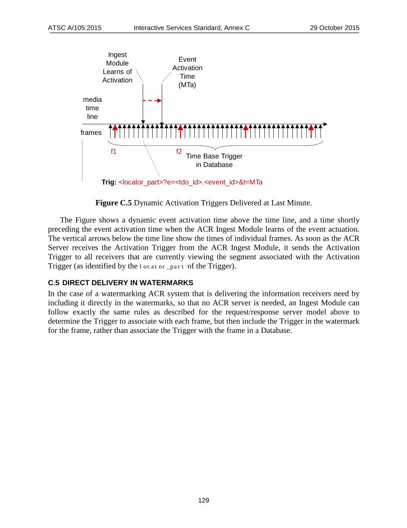
ATSC A/105:2015 Interactive Services Standard, Annex C 29 October 2015
129
Figure C.5 Dynamic Activation Triggers Delivered at Last Minute.
The Figure shows a dynamic event activation time above the time line, and a time shortly preceding the event activation time when the ACR Ingest Module learns of the event actuation. The vertical arrows below the time line show the times of individual frames. As soon as the ACR Server receives the Activation Trigger from the ACR Ingest Module, it sends the Activation Trigger to all receivers that are currently viewing the segment associated with the Activation Trigger (as identified by the locator_part of the Trigger).
C.5 DIRECT DELIVERY IN WATERMARKS In the case of a watermarking ACR system that is delivering the information receivers need by including it directly in the watermarks, so that no ACR server is needed, an Ingest Module can follow exactly the same rules as described for the request/response server model above to determine the Trigger to associate with each frame, but then include the Trigger in the watermark for the frame, rather than associate the Trigger with the frame in a Database.
Trig: <locator_part>?e=<tdo_id>.<event_id>&t=MTa
EventActivation
Time (MTa)
frames
Ingest Module
Learns ofActivation
Time Base Triggerin Database
mediatimeline
f1 f2

ATSC A/105:2015 Interactive Services Standard, Annex D 29 October 2015
130
Annex D: Trigger Transport
D.1 SCOPE The following sections specify the delivery of trigger-related data within the CEA-708 [14] caption data stream. Standard caption services shall be as defined in CEA-708 [14] with code points and data as defined in the paragraphs below.
D.2 TRANSPORT Trigger-related data is delivered in CEA-708 [14] Standard caption service #6.
D.3 SEGMENTATION AND REASSEMBLY The command specified below delivers a payload that may be segmented for delivery to overcome the size limitations of one syntactic element. All segments of a segmented command shall be placed into the Caption Channel Packet(s) in the order in which they are to be reassembled. All segments a given segmented command shall be placed into the multiplex without segments of any other variable-length command intervening.
Receivers are expected to implement a reassembly buffer to handle the variable-length commands defined in this standard. The receiver is expected to set the size of the reassembly buffer to accommodate the largest payload it is designed to support. Receivers are expected to discard the contents of the reassembly buffer and reinitialize the reassembly processing if any of the following conditions occurs:
• A segment of a different variable length-command arrives before the final segment of the current command arrives;
• More than two seconds has elapsed since the arrival of the most-recently received segment; • The inclusion into the reassembly buffer of a newly arrived segment would overflow the
buffer if it were to be added.
D.4 SDO PRIVATE DATA Name: SDOPrivateData – A command that delivers a variable-length payload defined in
standards developed by an identified SDO. Format: Variable-length Command Coding:
b7 b6 b5 b4 b3 b2 b1 b0
0 0 0 1 0 0 0 0 EXT1
1 0 0 1 1 0 0 0 0x98
T1 T0 pr L4 L3 L2 L1 L0
cid7 cid6 cid5 cid4 cid3 cid1 cid1 cid0
SDO_payload() (variable length)

ATSC A/105:2015 Interactive Services Standard, Annex D 29 October 2015
131
Description –The SDOPrivateData command may be used to deliver data whose syntax and semantics are defined in standards developed by other SDOs. The SDOPrivateData command is carried in Standard service #6 using the syntax and semantics defined below. EXT1 shall be coded per CEA-708 [14] (value 0x10).
Parameters – Type (T) is a 2-bit field that shall indicate whether the instance of the SDOPrivateData command is part of a segmented variable-length command, as defined in Section 7.1.11.2 of CEA-708 [14], and if so, whether the instance is the first, middle or last segment. The Type field in the SDOPrivateData command shall be encoded as specified in Section 7.1.11.2 of CEA-708 [14]. • pr is a flag that shall indicate, when set to ‘1’, that the content of the command is asserted
to be Program Related. When the flag is set to ‘0’, the content of the command is not so asserted.
• Length (L) is an unsigned integer that shall indicate the number of bytes following the header, in the range 2 to 27, and shall be represented in the SDOPrivateData command as the set of bits L4 through L0 where L4 is most significant and L0 is least significant.
• cid (cmdID) is an 8-bit field that shall identify the SDO that has defined the syntax and semantics of the SDO_payload() data structure to follow. The cmdID field shall be encoded as specified in Table D.1 below.
Table D.1 cmdID field Encoding
cmdID value Meaning
0x00-0x1F Advanced Television Systems Committee (ATSC)
0x20-0x3F Society of Cable Telecommunications Engineers (SCTE)
0x40-0x5F Society of Motion Picture & Television Engineers (SMPTE)
0x60-0xFF Reserved
When the SDOPrivateData command is delivered in multiple segments (T <> ‘11’), the cmdID field shall be included in each segment.
D.4.1 SDO Payload The syntax and semantics of SDO_payload() shall be as specified in standards published by the SDO identified in the cmdID field that reference the present standard.
ATSC A/105:2015 Interactive Services Standard, Annex E 29 October 2015
132
Annex E: PDI Registration
E.1 PDI REGISTRATION RECORD Each registration record includes:
• Question ID (globally unique, as specified in Section 8.2 of this document) • Question type (QIA, QBA, QSA, or QTA) • Question text (in one or more languages) • In the case of a QSA, the allowable selections (identifier of each selection, and the text of
each selection in one or more languages) • Date of registration • Name of the organization submitting the question for registration • Contact information for the organization submitting the question for registration
E.2 REGISTERED AND NON-REGISTERED QUESTIONS A PDI table may contain a mix of registered and non-registered questions.
Both registered and non-registered questions may appear in multiple PDI tables. Whenever a user answers a question that appears in multiple PDI tables, whether by a function provided by the receiver or by an application, the answer is expected to propagate to all instances of the question in all the questionnaires where it appears. Thus, a user only needs to answer any given question once, no matter any many times it appears in different questionnaires.
To avoid having users be deluged with questions, it is recommended that questionnaire creators use registered questions whenever possible, and only use non-registered questions when the questionnaire creator has unique targeting needs that cannot be met with registered questions.
–End of document–