atp 6-02.53 techniques for tactical radio ......atp 6-02.53 techniques for tactical radio operations...
TRANSCRIPT

ATP 6-02.53
TECHNIQUES FOR TACTICAL RADIO OPERATIONS
FEBRUARY 2020
DISTRIBUTION RESTRICTION: Approved for public release; distribution is unlimited.
This publication supersedes ATP 6-02.53, dated 7 January 2016.
Headquarters, Department of the Army

This publication is available at the Army Publishing Directorate
Website (https://armypubs.army.mil/) and the Central Army Registry
site (https://atiam.train.army.mil/catalog/dashboard).

*ATP 6-02.53
DISTRIBUTION RESTRICTION: Approved for public release; distribution is unlimited.
*This publication supersedes ATP 6-02.53, dated 7 January 2016.
ATP 6-02.53 i
Army Techniques Publication
No. 6-02.53
Headquarters
Department of the Army
Washington, DC, 13 February 2020
Techniques for Tactical Radio Operations
Contents
Page
PREFACE................................................................................................................... vii
INTRODUCTION ......................................................................................................... ix
Chapter 1 OVERVIEW ............................................................................................................... 1-1 Tactical Radios .......................................................................................................... 1-1 Tactical Radio Networks ............................................................................................ 1-2 Network Management Planning Tools ...................................................................... 1-4 Capabilities ................................................................................................................ 1-6 Land Mobile Radio ..................................................................................................... 1-6 Combat Survivor Evader Locator .............................................................................. 1-7
Chapter 2 TACTICAL RADIO EMPLOYMENT BY ECHELON ................................................. 2-1 Combatant Commander Communications Team ...................................................... 2-1 Signal Command (Theater) ....................................................................................... 2-3 Corps and Below ....................................................................................................... 2-4 Special Operations Forces ........................................................................................ 2-5 Tactical Command Post ............................................................................................ 2-6
Chapter 3 TACTICAL RADIO PLATFORMS ............................................................................ 3-1
Section I – Legacy and Enduring Radio Platforms .............................................. 3-1 Single-Channel Ground and Airborne Radio System ................................................ 3-1 Defense Advanced Global Positioning System Receiver ........................................ 3-12 MicroLight Personal Software-Defined Networked Radio ....................................... 3-13 High Frequency Radios ........................................................................................... 3-13 Blue Force Tracking ................................................................................................ 3-18 Force XXI Battle Command, Brigade and Below Joint Battle Command Platform . 3-19 Force XXI Battle Command, Brigade and Below Joint Capabilities Release .......... 3-19
Section II – Software Defined Radio Platforms .................................................. 3-19 Handheld Manpack Small Form Fit ......................................................................... 3-20 Manpack Radio ........................................................................................................ 3-21
Chapter 4 WAVEFORMS AND WAVEFORM APPLICATIONS ............................................... 4-1 Lower Tier Waveforms .............................................................................................. 4-1 Waveform Applications .............................................................................................. 4-2
Chapter 5 VHF RADIOS ............................................................................................................ 5-1 Multiband Inter/Intra Team Radio .............................................................................. 5-1 Wideband Networking Handheld Radio .................................................................... 5-2 Multichannel Manpack Radio .................................................................................... 5-3

Preface
ii ATP 6-02.53 13 February 2020
Chapter 6 ULTRAHIGH FREQUENCY RADIOS ...................................................................... 6-1 Multifunctional Information Distribution System ........................................................ 6-1 Tactical Digital Information Link Joint Terminals ...................................................... 6-1 Joint Tactical Information Distribution System .......................................................... 6-2 Battlefield Awareness and Targeting System-Dismounted ...................................... 6-3
Chapter 7 AIRBORNE RADIOS ................................................................................................ 7-1 AN/ARC-201 Radio ................................................................................................... 7-1 AN/ARC-210 Radio ................................................................................................... 7-1 AN/ARC-220 Radio ................................................................................................... 7-2 AN/ARC-231 Radio ................................................................................................... 7-2 AN/ARC-186 Radio ................................................................................................... 7-3
Chapter 8 ANTENNA TECHNIQUES ........................................................................................ 8-1 Antenna Techniques Overview ................................................................................. 8-1 High Frequency Antenna Location Considerations .................................................. 8-1 Ground Effects .......................................................................................................... 8-9 Grounded Antenna Theory ..................................................................................... 8-10 Antenna Length ....................................................................................................... 8-12 Antenna Orientation ................................................................................................ 8-13 Improvement of Marginal Communications ............................................................ 8-15 Types of Antennas .................................................................................................. 8-15 Field Repair ............................................................................................................. 8-30
Chapter 9 TACTICAL RADIO KEY MANAGEMENT ................................................................ 9-1 Key Management Infrastructure ................................................................................ 9-1 Key Distribution ......................................................................................................... 9-2 Automated Communications Engineering Software ................................................. 9-2 Loadsets .................................................................................................................... 9-4
Chapter 10 ELECTRONIC WARFARE AND PROTECTION TECHNIQUES ........................... 10-1 Electronic Warfare ................................................................................................... 10-1 Electronic Protection Responsibilities ..................................................................... 10-3 Communications Planning Process ........................................................................ 10-5 Signal Security ........................................................................................................ 10-7 Emission Control ..................................................................................................... 10-7 Preventive Electronic Protection Techniques ......................................................... 10-8 Single-Channel Ground and Airborne Radio System Anti-Jamming .................... 10-14 Electronic Warfare for Single-Channel Tactical Satellite ...................................... 10-15 Counter Radio-Controlled Improvised Explosive Device Electronic Warfare ....... 10-17 Purposeful Interference ......................................................................................... 10-17 Electromagnetic Interference ................................................................................ 10-17
Appendix A FREQUENCY MODULATION RADIO NETWORKS ............................................... A-1
Appendix B SINGLE-CHANNEL RADIO COMMUNICATIONS TECHNIQUES ......................... B-1
Appendix C ANTENNA SELECTION ........................................................................................... C-1
Appendix D COMMUNICATIONS IN AUSTERE ENVIRONMENTS ........................................... D-1
Appendix E JULIAN DATE, SYNCHRONIZATION TIME, AND TIME CONVERSION ............... E-1
Appendix F RADIO COMPROMISE RECOVERY PROCEDURES ............................................. F-1
Appendix G DATA COMMUNICATIONS ..................................................................................... G-1
Appendix H COSITE INTERFERENCE ........................................................................................ H-1
Appendix I RADIO OPERATING PROCEDURES ....................................................................... I-1
Appendix J FIELD REPAIR OF ANTENNAS .............................................................................. J-1

Preface
13 February 2020 ATP 6-02.53 iii
Appendix K SINGLE-CHANNEL TACTICAL SATELLITE COMMUNICATIONS ....................... K-1
GLOSSARY ................................................................................................ Glossary-1
REFERENCES ........................................................................................ References-1
INDEX ................................................................................................................ Index-1
Figures
Figure 3-1. Retransmission operations ........................................................................................ 3-10
Figure 3-2. Defense Advanced Global Positioning System receiver ........................................... 3-13
Figure 8-1. Transmitter and receiver connection example ............................................................. 8-2
Figure 8-2. Components of electromagnetic waves ....................................................................... 8-3
Figure 8-3. Solid radiation patterns ................................................................................................ 8-4
Figure 8-4. Vertically polarized wave ............................................................................................. 8-5
Figure 8-5. Horizontally polarized wave ........................................................................................ 8-6
Figure 8-6. Circular polarization ..................................................................................................... 8-7
Figure 8-7. Antenna take-off angle ................................................................................................. 8-9
Figure 8-8. Quarter-wave antenna connected to ground ............................................................. 8-10
Figure 8-9. Wire counterpoise ...................................................................................................... 8-12
Figure 8-10. Beamwidth .............................................................................................................. 8-14
Figure 8-11. Example of a declination diagram ............................................................................ 8-14
Figure 8-12. Near-vertical incidence skywave antenna, AS-2259/GR ......................................... 8-16
Figure 8-13. V antenna ................................................................................................................. 8-17
Figure 8-14. Vertical half-rhombic antenna .................................................................................. 8-18
Figure 8-15. Long-wire antenna ................................................................................................... 8-19
Figure 8-16. Sloping-V antenna ................................................................................................... 8-20
Figure 8-17. Inverted L antenna ................................................................................................... 8-21
Figure 8-18. Near-vertical incidence skywave propagation ......................................................... 8-22
Figure 8-19. Whip antenna ........................................................................................................... 8-23
Figure 8-20. Whip antennas mounted on a vehicle...................................................................... 8-24
Figure 8-21. OE-303 half-rhombic VHF antenna ......................................................................... 8-26
Figure 8-22. Half-wave dipole (doublet) antenna ......................................................................... 8-27
Figure 8-23. Center-fed half-wave antenna ................................................................................. 8-28
Figure 8-24. Improvised vertical half-wave antenna .................................................................... 8-29
Figure 8-25. Field repair of broken whip antennas ....................................................................... 8-31
Figure 8-26. Examples of field expedient antenna insulators ...................................................... 8-32
Figure 8-27. Repaired antenna guy lines and masts ................................................................... 8-33
Figure 10-1. Local interference resolution (Army victim) ........................................................... 10-19
Figure 10-2. Interference resolution (Army source) ................................................................... 10-20
Figure A-1. Structure of a division command network ...................................................................A-3
Figure A-2. Example of a brigade administrative and logistics network.........................................A-4
Figure A-3. Example of a division operations and intelligence communications network..............A-5

Preface
iv ATP 6-02.53 13 February 2020
Figure A-4. Example of a corps medical operations network ........................................................ A-6
Figure A-5. Example of a medical operations network in a division .............................................. A-7
Figure A-6. Example of a division sustainment area command network ....................................... A-8
Figure A-7. Example of a division HF command network .............................................................. A-9
Figure A-8. Example of a cavalry squadron HF data network ..................................................... A-10
Figure B-1. Radiation of radio waves from a vertical antenna ....................................................... B-3
Figure B-2. Wavelength of a radio wave ........................................................................................ B-3
Figure B-3. Principal paths of radio waves .................................................................................... B-4
Figure B-4. Possible routes for ground waves ............................................................................... B-4
Figure B-5. Average layer distribution of the ionosphere .............................................................. B-6
Figure B-6. Skywave transmission paths ....................................................................................... B-8
Figure B-7. Skywave transmission hop paths................................................................................ B-9
Figure B-8. Wave shapes ............................................................................................................ B-13
Figure B-9. Amplitude modulation system ................................................................................... B-14
Figure B-10. Single-sideband system .......................................................................................... B-15
Figure C-1. 32-foot vertical whip, vertical antenna pattern ............................................................ C-3
Figure E-1. World time zone map .................................................................................................. E-5
Figure H-1. Possible antenna stacks ............................................................................................. H-3
Figure J-1. Field repair of broken whip antennas ........................................................................... J-1
Figure J-2. Examples of field expedient antenna insulators ........................................................... J-2
Figure J-3. Repaired antenna guy lines and masts ........................................................................ J-3
Figure K-1. Single-Channel Anti-Jam Man-Portable terminal interface with combat net radio ..... K-4
Tables
Table 3-1. Comparison of SINCGARS versions and components ................................................ 3-3
Table 3-2. SINCGARS enhancements comparison ...................................................................... 3-5
Table 3-2. SINCGARS enhancements comparison (continued) ................................................... 3-6
Table 3-3. Minimum antenna separation distance ....................................................................... 3-11
Table 3-4. AN/VRC-100 configurations ....................................................................................... 3-15
Table 3-5. Automatic link establishment system handshake ....................................................... 3-17
Table 3-6. Notional link quality analysis matrix for a radio (B3B) ................................................ 3-17
Table 8-1. Antenna length calculations ........................................................................................ 8-13
Table 8-2. Leg angle for V antennas ........................................................................................... 8-18
Table 8-3. Frequency and inverted L horizontal element length ................................................. 8-20
Table 8-4. OE-254 planning ranges ............................................................................................. 8-25
Table 9-1. Initializing Automated Communications Engineering Software or communications-electronics operating instructions and signal operating instructions data .................. 9-4
Table 10-1. Techniques for minimizing transmissions and transmission times ........................... 10-9
Table 10-2. Common jamming signals ...................................................................................... 10-12
Table 10-3. Army interference resolution program functions ..................................................... 10-18

Preface
13 February 2020 ATP 6-02.53 v
Table 10-4. Joint spectrum interference resolution security classification guide ....................... 10-21
Table 10-5. Joint spectrum interference resolution information requirements ........................... 10-22
Table A-1. Example of division command networks ......................................................................A-2
Table B-1. Surface conductivity......................................................................................................B-5
Table B-2. Ionosphere layers .........................................................................................................B-6
Table B-3. Regular variations of the ionosphere ............................................................................B-7
Table B-4. Irregular variations of the ionosphere ...........................................................................B-7
Table C-1. Take-off angle versus distance ................................................................................... C-2
Table C-2. HF antenna selection matrix ........................................................................................ C-4
Table E-1. Two-digit Julian date calendar (regular year) ...............................................................E-2
Table E-2. Two-digit Julian date calendar (leap year) ...................................................................E-3
Table E-3. Example of world time zone conversion (standard time) ..............................................E-4
Table F-1. Compromised network recovery procedures: compromised transmission encryption keys and key encryption keys ..................................................................................... F-2
Table F-2. Compromised network recovery procedures: compromised transmission encryption keys F-3
Table H-1. Transmitters and transmission range with and without the frequency hopping multiplexer .................................................................................................................. H-4
Table I-1. Phonetic alphabet ........................................................................................................... I-1
Table I-2. Numerical pronunciation ................................................................................................. I-2
Table I-3. Numerals in combinations ............................................................................................... I-2
Table I-4. Procedure words listed alphabetically ............................................................................. I-3
Table K-1. AN/PSC-5/C/D, AN/PRC-117F and AN/ARC-231 line of sight interoperability ............K-7
Table K-2. AN/PSC-5/C/D, AN/ARC-231 and AN/PRC-117F ........................................................K-8

This page intentionally left blank.

13 February 2020 ATP 6-02.53 vii
Preface
ATP 6-02.53 is the primary doctrine publication for tactical radios and tactical radio networks. This
publication describes the non-prescriptive methods to perform missions, functions, and tasks for the
employment of tactical radio networks to support every warfighting function and enable command and
control of Army forces.
This publication includes doctrine on new communications and networking capabilities. It addresses the
employment of interdependent and interoperable enterprise and tactical systems in the tactical network.
This publication supports the Army’s goal to provide an integrated network that is interoperable across
all mission environments during all phases of operations. This publication implements North Atlantic
Treaty Organization standardization agreement 4538, Technical Standards for an Automatic Radio
Control System for High Frequency Communication Links.
The principal audience for ATP 6-02.53 is commanders, staffs, supervisors, planners, radio operators,
signal Soldiers, and other personnel responsible for operating tactical radios or employing tactical radio
networks across multiple domains, at all echelons. ATP 6-02.53 is a standard reference for tactical radios.
It provides system planners with guidance and steps for network planning, interoperability
considerations, and equipment capabilities.
Commanders, staffs, and subordinates ensure that their decisions and actions comply with applicable
United States, international, and in some cases host-nation laws and regulations. Commanders at all
levels ensure that their Soldiers operate in accordance with the law of war and the rules of engagement.
(See FM 6-27.)
ATP 6-02.53 uses joint terms where applicable. Selected joint and Army terms and definitions appear in
both glossary and the document. Terms for which ATP 6-02.53 is the proponent publication (the
authority) are italicized in the text and marked with an asterisk (*) in the glossary. Terms and definitions
for which ATP 6-02.53 is the proponent publication are boldfaced in the text. For other definitions shown
in the text, the term is italicized and the number of the proponent publication follows the definition.
ATP 6-02.53 applies to the Regular Army, Army National Guard/Army National Guard of the United
States, and United States Army Reserve unless otherwise stated.
The proponent for this publication is the United States Army Cyber Center of Excellence. The preparing
agency is the Doctrine Branch, United States Army Cyber Center of Excellence. Send comments and
recommendations on a DA Form 2028 (Recommended Changes to Publications and Blank Forms) to
Commander, United States Army Cyber Center of Excellence and Fort Gordon, ATTN: ATZH-OP (ATP
6-02.53), 506 Chamberlain Avenue, Fort Gordon, GA 30905-5735; or e-mail to usarmy.gordon.cyber-

This page intentionally left blank.

13 February 2020 ATP 6-02.53 ix
Introduction
ATP 6-02.53 expands on the foundational information about tactical radios in FM 6-02. Tactical radios
are critical command and control enablers in unified land operations. Radio networks empower
subordinate decision making through the mission command approach. Tactical radio networks
synchronize and integrate the elements of combat power across all domains and the information
environment. Tactical radios and networks support the Army’s strategic roles to shape operational
environments, prevent conflict, conduct large-scale combat operations, and consolidate gains against a
peer threat.
Fluid tactical situations in sustained operations require versatile and adaptable tactical radios. Tactical
radios provide Army forces the capability to move and communicate from higher echelons down to the
squad level. Squad-level radios enable communication and situational awareness at the lowest level
possible. This publication presents techniques for Soldiers to execute the Signal Corps’ core competency
associated with network transport. This revision of ATP 6-02.53 includes updated information to address
new or modified single-channel radio systems.
ATP 6-02.53 has ten chapters and eleven appendixes—
Chapter 1 provides an overview of tactical radios, tactical radio networks, capabilities, and network
management.
Chapter 2 addresses the employment of tactical radios at all echelons of the Army.
Chapter 3 addresses the tactical radio platforms and associated waveforms that Army forces employ at
all echelons across all phases of operations.
Chapter 4 discusses the waveform and waveform application functional component of the tactical
networking environment.
Chapter 5 describes the commercial off-the-shelf VHF radios used to support tactical radio operations.
Chapter 6 addresses the ultrahigh frequency radios and systems that play a significant role in network
centric warfare.
Chapter 7 addresses the airborne radios employed to provide communications for ground-to-air
operations, air-to-air, and air-to-sea missions.
Chapter 8 addresses antenna techniques, concepts, terms, types, effects, and provides examples of
antenna field repairs.
Chapter 9 addresses key management techniques when protecting voice, data, and video information
over tactical radio networks.
Chapter 10 addresses electronic warfare and the electronic protection techniques used to prevent enemy
jamming and intrusion into friendly communications systems.
Appendix A describes frequency modulation networks.
Appendix B identifies radio sets essential components, characteristics, properties of radio waves, wave
modulation, and site considerations for single-channel radios.
Appendix C addresses HF, VHF, UHF antennas.
Appendix D addresses radio operations in unusual environments.
Appendix E addresses the Julian date, synchronization time, and ZULU time. It also provides a time
zone conversion chart.

Chapter 1
x ATP 6-02.53 13 February 2020
Appendix F provides procedures for preventing a network compromise and addresses recovery options
available to the commander and staff.
Appendix G addresses data communications elements as binary data, baud rate, modems, and forward
error correction.
Appendix H addresses single-channel ground airborne radio system implications and cosite interference
mitigation.
Appendix I addresses the proper way to pronounce letters and numbers when sending messages over
the radio and the proper procedures for opening and closing a radio net.
Appendix J provides recommendations on repairing antennas and antenna supports.
Appendix K consists of tactical satellites, communications planning considerations, ultrahigh frequency
terminals, fire support networks, and airborne and air assault units.

13 February 2020 ATP 6-02.53 1-1
Chapter 1
Overview
This chapter introduces tactical radio operations, radio networks, and radio network
management across all phases of operations to support warfighting functions. Radios
are not stand-alone capabilities, but they are complete interoperable networks that
provide commanders with a mobile ad hoc networking environment.
TACTICAL RADIOS
1-1. Tactical radios are a necessity for Soldiers during military operations. Squad leaders and higher use
tactical radios to communicate and share a common view of the operational environment. Tactical radios
provide Soldiers the ability to send and receive voice, data, and video communication. Tactical radio systems
are the primary means for Soldiers to communicate during operations.
TACTICAL RADIOS IN ARMY OPERATIONS
1-2. Army forces employ a variety of tactical radios and waveforms to shape operational environments,
prevent conflict, conduct large-scale combat operations, and consolidate gains in operations in multiple
domains. Tactical radios and waveforms support the Army’s enterprise initiative to be an integrated and
interoperable network from the highest to the lowest echelon.
1-3. A wide variety of tactical radios support tactical communications. These radios include—
High frequency (HF) radios.
Very high frequency (VHF) radios.
Ultrahigh frequency (UHF) radios.
Multiband radios.
Multimode radios.
Secure wireless broadband solutions microwave radios.
1-4. Enemies may use electronic warfare (EW) capabilities to interfere with U.S. communications. Radio
operators must learn to recognize and respond to enemy EW efforts. Chapter 10 discusses enemy EW and
electronic protection techniques in detail.
TERRESTRIAL AND SATELLITE COMMUNICATIONS PRODUCTS
1-5. Terrestrial and satellite communications (SATCOM) radios are software-defined radio systems that
enable communications to the lowest level and support current and future communication for all services.
Terrestrial and SATCOM radio configurations include—
Airborne.
Maritime.
Terrestrial fixed station.
Vehicular.
Handheld and man-pack.
1-6. These radios enable connectivity throughout the area of operations. Chapters 3 and 4 discuss the
tactical radio platforms and associated waveforms used by Army forces in detail.

Chapter 1
1-2 ATP 6-02.53 13 February 2020
TACTICAL RADIO NETWORKS
1-7. Tactical radio networks play a vital role in facilitating command and control and providing situational
awareness during operations. The primary function of tactical radio networks is voice transmission to enable
communication and situational awareness at all echelons, across all phases of operations. It assumes a
secondary role for data transmission where other data capabilities do not exist. Tactical radio networks are
located at every echelon in the tactical force. Each echelon employs radio-based systems to provide voice
and data communication during all phases of operations in the most austere environments and provides
situational awareness to support mission accomplishment. Tactical radio networks provide the principal
means for facilitating communication between Army and joint forces. Tactical radio networks support Army
forces’ requirements for a horizontally and vertically integrated digital information network. Tactical radio
networks facilitate communication and situational understanding, which enhances the military decision
making process by providing reliable and secure communications connectivity.
1-8. As technology changes, tactical radio capabilities change and incorporate into the network. The
capability enhancements enable web services at a command post allows command and control on the move
capabilities in leader vehicles, and extends the data network to mounted and dismounted platoon leaders, and
team leaders operating on handheld Android devices. The enhancements improve the overall accuracy of
position location information and reduce the latency of information to the Soldier.
TACTICAL NETWORK
1-9. The tactical network is the physical communications network that provides the data backbone to
support the exchange of digital information as communication and situational awareness messages. A
communications network is an organization of stations capable of intercommunications, but not necessarily
on the same channel (JP 6-0). A message is any thought or idea expressed briefly in a plain or secret language
and prepared in a form suitable for transmission by any means of communication. (JP 6-0). The tactical
network includes the following—
Combat net radios.
Single-channel ground and airborne radio system (SINCGARS).
Vehicular and dismounted mission command systems.
Joint Battle Command Platform.
Nett Warrior.
Ad hoc self-forming networks.
Blue Force Tracking (BFT) I and II.
1-10. The tactical network forms two distinct information exchanges, the upper tier, and the lower tier. The
upper tier consists of multi-channel satellite systems and other Warfighter Information Network-Tactical
(WIN-T) systems. The lower tier is the networking environment that consists of communications support
systems by units at brigade and below.
Upper Tier
1-11. The upper tier tactical internet provides high-throughput networking at-the-halt to corps command
posts, and at-the-halt or on-the-move at the division and brigade combat team. The upper tier extends the
DODIN, to deployed forces. The upper tier uses WIN-T nodes to extend SECRET Internet Protocol Router
Network, Non-classified Internet Protocol Router Network, and Joint Worldwide Intelligence
Communications System from the regional hub node to command posts at corps, division, and brigade. For
more information about the upper tier tactical internet, refer to ATP 6-02.60.
Lower Tier
1-12. The lower tier supports tactical formations down to the team leader with data and voice
communications and provides situational awareness information, friendly and enemy locations. The lower
tier consists of interconnected voice and data, tactical radios, and operates simultaneously and transparently
to the user.

Overview
13 February 2020 ATP 6-02.53 1-3
1-13. The lower tier has combat net radios at the lowest tactical level using software-defined radios in
mounted and mobile configurations. The lower tier enables commanders and Soldiers to exchange secure and
protected terrestrial and satellite-based voice and data communication at all echelons. Satellite-based
communications consist of narrowband SATCOM capabilities.
1-14. The lower tier is composed of five primary functional components—
Radio platforms.
Waveforms and waveform applications.
Network Operations Management System.
Ancillary devices.
Mission command mounted and mobile applications management.
1-15. When combined, these components form a complete network capability that enables commanders to
exchange protected terrestrial and satellite voice and data across their entire formations. The lower tier
requires that all functional components operate simultaneously. The failure of a single functional component
to initialize and operate jeopardizes the overall lower tier capability.
Radio Platforms
1-16. Radio platforms are composed of a mix of all legacy radios and newly developed software defined
radios. The radio platform component is a combination of the hardware, which includes antenna, batteries,
operational devices, and the software design inherent in the radio operating system. The radio operating
system software allows the interaction between the radio hardware components and the Network Operations
Management System and Waveform Applications component software.
1-17. The hardware and software link together less rigidly in software defined radios. Software defined
radios provide greater interoperability with waveform applications and network management tools while
minimizing interoperability issues associated with the enhanced radio platform operating system. Radio
platforms provide a comprehensive and overarching system of systems capability for the maneuver
commander. Radios are not stand-alone systems but rather a complete set of interoperable networks that
provide a maneuver commander with a mobile ad hoc networking environment based on flexible and resilient
internet protocol (IP) based messaging.
Waveforms and Waveform Applications
1-18. The waveform application component is composed of all current software defined waveform
applications that provide a means for passing voice, data, and video across the transport layer of the tactical
radio network. Waveform applications are peer-to-peer programs that facilitate data exchange across the
spectrum of radio networks. The optimization of each waveform application meets the mission needs of the
portion on which it operates. These are important considerations for tactical radio network planners as they
develop their network architecture to meet their commander’s communication requirements. Plan, configure,
and load waveform applications onto the radio platforms through the Network Operations Management
System.
Network Operations Management System
1-19. The Network Operations Management System is the integrated capability that allows network
managers to plan, configure, manage, and monitor all other components of the terrestrial and satellite-based
tier of a tactical radio network. The Network Operations Management System also includes radio platforms,
mission command mobile/mounted applications, ancillary devices, and waveform applications. The Network
Operations Management System is the capability through which the battalion or brigade signal staff officer
(S-6) develops a network plan and initializes and operates the radio network for their respective command
level. The functional integration of Department of Defense information network operations capabilities
across the radio platform operating system, the waveform application software, and the Network Operations
Management System results in the achievement of network operations. The battalion S-6 conducts many
tasks manually to ensure the proper planning and configuration of the network, and to ensure proper
management of the component devices of the network.

Chapter 1
1-4 ATP 6-02.53 13 February 2020
Ancillary Devices
1-20. Ancillary devices encompass all the networked and non-networked items that connect directly to the
radio platform or enable the routing and transmission of data between radios, or security environments. These
devices include talk selector switches that connect to the radio platform and provide cross-domain solutions,
gateways for joint and multinational interoperability, enterprise services to support positioning, navigation,
and timing provided by the Global Positioning System (GPS). Networked ancillary devices provide critical
interconnectivity capability between radio networks and ensure that voice and data are processed and routed
as prioritized by the commander.
Mission Command Mobile and Mounted Applications Management
1-21. The battalion S-6 staff is ensures proper planning, configuration, and initialization of mission
command applications that operate on mounted platforms and mobile dismounted Soldier’s platforms to
support the commander’s mission. This responsibility requires the proper alignment of mounted and mobile
applications with more fixed and traditional applications residing on the battle command common services
stack of servers and other key information repository sources. The battalion S-6 ensures the proper alignment
and interoperability between the mission command applications and the transport network of their battalion.
1-22. Mounted applications consist of native applications built onto the Mounted Computing Environment
Software Development Kit. Mounted applications share common components, user interfaces, and
communication methods as the GPS and Joint Battle Command-Platform web services. Web services are
applications accessed via a web browser and run as local web services with limited shared data as web mail
and Command Post of the Future thin client. Virtual machines run as stand-alone applications on mounted
platforms with minimal sharing.
1-23. Mobile applications consist of two categories, those that run natively on the mobile platform and those
accessed as web services. The web service configured on a remote server is the mobile device subscribes to
with an IP address provided by the controlling authority. The battalion S-6 configures native mobile
applications with a planning tool. With this tool, the battalion S-6 can create, assemble, manage, and transfer
mission data. Mission data includes digital map files, the unit task organization, photo image files, and other
files to support the mission. Before putting the mobile device into operation, the battalion S-6 ensures the
conversion of a map into a format accepted by the mobile platform. Using the planning tool, the battalion S-
6 provides all imported files, free of viruses or other destructive code, to the mobile platform.
NETWORK MANAGEMENT PLANNING TOOLS
1-24. The network management tools for the mission command network do not operate as a stovepipe
environment. A universal approach to network planning and management enables the accomplishment of
network management at the tactical level. The effectiveness of the lower tier portion of network centric
warfare depends mainly on network planners’ ability to plan complex mobile networks, share the network
planning data across a joint operational environment, view network performance data, and provide situational
awareness data across the different tiers. The network management tools enable Soldiers to operate in a net-
centric environment without overburdening the network planners and managers with complexity.
1-25. The following planning tools used for current radio systems in the lower tier—
Joint Automated Communications Electronics Operating Instruction System and Automated
Communications Engineering Software.
Joint Enterprise Network Manager.
Tactical Internet Management System.
Coalition Joint Spectrum Management Planning Tool.
Systems Planning, Engineering and Evaluation Device.

Overview
13 February 2020 ATP 6-02.53 1-5
JOINT AUTOMATED COMMUNICATIONS-ELECTRONICS OPERATING INSTRUCTION SYSTEM
AND AUTOMATED COMMUNICATIONS ENGINEERING SOFTWARE
1-26. Joint Automated Communications-Electronics Operating Instruction System and Automated
Communications Engineering Software allow the S-6 staff to perform pre-deployment and post-mission
planning radio network planning. The S-6 staff’s radio network planning ensures interoperability of radio
frequency (RF) networks, cryptographic key tag generation, transmission security key generation, signal
operating instructions production, and radio network planning.
1-27. Signal operating instructions are a series of orders issued for technical control and coordination of the
signal communication activities of a command (JP 6-0). The Automated Communications Engineering
Software provides the capability to support black key packaging, and distribution provides fills for the simple
key loader (SKL) AN/PYQ-10 with secure network information through a direct cable connection or over-
the-air rekey. Pre and post-mission planning also consist of electronic protection (EP) data and radio network
engineering for secure communication. The Joint Automated Communications Electronics Operating
Instruction System and Automated Communications Engineering Software support the following radios—
Harris Radios—
Falcon III (AN/PRC-117G).
Falcon III (AN/PRC-152A and AN/PRC-160V).
Legacy radios—
SINCGARS.
AN/PSC-5.
AN/PRC-150.
AN/PRC-117F.
JOINT ENTERPRISE NETWORK MANAGER
1-28. The Joint Enterprise Network Manager (JENM) is a consolidated software application for planning,
loading, managing, securing, and defending lower tier software-defined radios and their waveforms. The
JENM provides the ability to plan waveform applications and parameter settings, and the ability to extract
radio configuration files from a network plan. The JENM provides pre-deployment network management
planning for waveform parameters of radios. The JENM processes configuration files tailored to the radio
type. It can load the configuration file to a radio, fill device, optical storage media, or USB device. The JENM
also provides post-deployment support in monitoring and controlling the deployed networks and radios.
TACTICAL INTERNET MANAGEMENT SYSTEM
1-29. The Tactical Internet Management System is part of the Joint Battle Command-Platform Blue Force
Tracking. The system displays blue situational awareness icons generated by radio-based systems that report
their geospatial position via position location information for multicast messages. It also enables the S-6 to
maintain near real-time situational awareness. Implementation of radio-based situation awareness monitoring
provides the S-6 enhanced situational awareness. Using position location information reports received from
radios and hand-held devices enables the radio-based situation awareness system to validate position location
information reporting and infer radio up or down status across multiple networks.
COALITION JOINT SPECTRUM MANAGEMENT PLANNING TOOL
1-30. The Coalition Joint Spectrum Management Planning Tool (CJSMPT) is the visualization and planning
tool enables communications planners to automate and accelerate spectrum planning, making it easier for
troops to communicate while avoiding interference from jamming. CJSMPT enable planners to manage the
spectrum by displaying a real-time, three-dimensional view of frequency use in the battlespace for land, air,
and space emitters. The system automates planning and manages battlefield spectrum use. A key feature of
CJSMPT is its faster-than-real-time simulation capability that can predict and visualize potential interference
from on-the-move forces. Before this tool, military planners anticipated interference based on static analysis,
which tended to cause overly pessimistic solutions and loss of opportunity for spectrum reuse. By

Chapter 1
1-6 ATP 6-02.53 13 February 2020
coordinating all emitters and knowing their locations in a region, spectrum planners now are able to boost
reuse and significantly increase communication bandwidth to coalition forces.
SYSTEMS PLANNING, ENGINEERING, AND EVALUATION DEVICE
1-31. The Systems Planning, Engineering, and Evaluation Device (SPEED) is a communications planner
that plans, models, and analyze radio and jammer effects in a defined electromagnetic spectrum environment
to better understand where communications degradation or interoperability issues that may occur. The
electromagnetic spectrum is the range of frequencies of electromagnetic radiation from zero to infinity. It is
divided into 26 alphabetically designated bands (JP 3-13.1). SPEED has a 3D mapping and mission planning
capabilities, including frequency-dependent rejection interference analysis, enhanced jammer modeling, and
effectiveness prediction.
CAPABILITIES
1-32. Army forces employ various tactical radio systems to enable communication and situational awareness
during operations. The type of tactical radio system chosen for employment depends on mission
requirements.
1-33. Tactical radios enable communication for Army forces during unified land operations. Tactical radios
are versatile and adaptable to changing tactical situations. Key capabilities that tactical radios provide are—
Lightweight.
Portable.
Mobile ad hoc networking.
Applications.
Securable.
Multiple waveforms capable.
Multiband and multi-mode capable.
GPS capable.
Software-based radios that provide squad level networking and integrate with legacy platforms.
1-34. The capabilities provided by tactical radios enhance interoperable networking between the software
defined radio platform, legacy waveforms, and mobile ad hoc networking waveforms. The capabilities of
tactical radios leverage commercial technology and employ open-system architecture to ensure
interoperability and portability of each waveform. The capabilities provide commanders the ability to
exercise command and control and communicate with their forces via secure voice, video, and data mediums
during operations.
LAND MOBILE RADIO
1-35. The land mobile radio is the primary tactical system used for communications in garrison. The land
mobile radio supports administrative activities for public safety organizations in garrison. The land mobile
radio enhances communications interoperability with state and local agencies when conducting homeland
defense or defense support of civil authorities’ missions. The land mobile radio provides non-secure logistics
and administrative communications to first responders.
1-36. Land mobile radio systems range from single-channel analog to digital trunked systems. The most
basic land mobile radio systems are single-channel analog systems. Each radio is set to a frequency monitored
by everyone using the same channel. These systems have a dedicated channel for each group or agency using
the system. In smaller agencies, if the system experiences heavy usage, users may not be able to place calls.
Many of these systems are VHF systems that offer very little flexibility in their operations.
1-37. Trunked systems use a relatively small number of paths or channels, like commercial telephones.
Rather than having a dedicated line for every user, the phone company has a computer switch that manages
many calls over a relatively small number of telephone lines. The assumption is that not every user requires
a line at the same time.

Overview
13 February 2020 ATP 6-02.53 1-7
1-38. A control console, repeaters, and radios generally make up trunked systems. Instead of using switches
and phone lines, these systems use consoles and channels or frequencies to complete calls. The process is the
dynamic allocation of a channel. When the user of a trunked system activates the push-to-talk, the system
automatically searches for an unused channel on which to complete the call.
1-39. Digital trunked systems offer better performance and provide a more flexible platform. This system
accommodates a more significant number of users and provides an open-ended architecture. This allows for
various modes of communications data, telephone-interconnect, and security functions. Faster system access,
more user privacy, and the ability to expand by providing a common air interface. For the continental United
States, land mobile radio regulations refer to the Manual of Regulations and Procedures for Federal Radio
Frequency Management (Redbook), chapter 10. The user and unit are responsible for obtaining a frequency
assignment in accordance with the Manual of Regulations and Procedures for Federal Radio Frequency
Management (Redbook), AR 5-12 and AR 25-1. The absence of spectrum authorization and assignments
prohibits the operation of RF systems.
1-40. The land mobile radio has the following characteristics and capabilities—
Frequency range of 380–470 MHz.
Power of 1–4 Watts.
Battery life of 10 hours.
Secure National Institute of Standards and Technology type 1 and type 3 encryption for point-to-
point voice communications.
Range of 5 kilometers (3.1 miles) maximum over smooth terrain.
Programming of up to 512 channels.
Easy radio reprogramming feature.
Immerse to a depth of 1 meter (3.2 feet) for 30 minutes.
Supports narrowband (12.5 kHz) and wideband (25 kHz) channel spacing.
Intra-squad and team communications for non-critical command, administrative, and logistics
functions.
COMBAT SURVIVOR EVADER LOCATOR
1-41. The Combat Survivor Evader Locator (CSEL) radio provides the capabilities required for locating and
rescuing downed aircrew members using SATCOM. The CSEL radio is the primary search and rescue system
used by special operations forces and aviation units.
1-42. The CSEL radio system is composed of three segments—over-the-horizon segment, ground segment,
and the user segment. The segments use GPS and other national systems to provide geo positioning and radio
communications for personnel recovery.
OVER-THE-HORIZON SEGMENT
1-43. The over-the-horizon segment operates over UHF SATCOM systems, and search and rescue satellite
assisted tracking. The UHF SATCOM mode supports two-way messaging and geo-position between the
AN/GRC-242 radio set base station and the AN/PRQ-7 radio set.
GROUND SEGMENT
1-44. The ground segment is composed of CSEL radio workstations and the ground distribution network
interconnecting with base stations. The ground segment provides a highly reliable and timely global
connection between all CSEL radio ground elements utilizing the Defense Information System Network.
USER SEGMENT
1-45. The user segment equipment consists of—
AN/PRC-7 handheld radio set.
J-6431/PRQ-7 radio set adapter, also referred to as the loader.

Chapter 1
1-8 ATP 6-02.53 13 February 2020
CSEL radio planning computer.
1-46. The AN/PRQ-7 provides data communications, geo-positioning, voice beacons. The radio set adapter
interfaces the CSEL radio planning computer and two AN/PRQ-7s. One AN/PRQ-7 serves as the reference
in the radio set adapter to acquire and store GPS almanac, ephemeris, and timing.
1-47. The CSEL radio planning computer loads the target AN/PRQ-7 with mission-specific data and
transfers GPS key loading. Loading current almanac and ephemeris data speeds up the satellite acquisition
process in the GPS receiver. Transfer of current GPS data speeds the calculation of user position and transfer
of current time allows faster acquisition of GPS.
1-48. The AN/PRQ-7 radio set has the following capabilities and characteristics—
Water-resistant.
GPS receiver.
Secure data UHF SATCOM transmit and receive capability.
VHF and UHF voice and beacon.
Low probability of exploitation of one-way transmission.
Search and rescue satellite transmission.

13 February 2020 ATP 6-02.53 2-1
Chapter 2
Tactical Radio Employment by Echelon
This chapter addresses the employment of tactical radios at various Army echelons.
Tactical radios support all warfighting functions at all echelons across all phases of
operations.
COMBATANT COMMANDER COMMUNICATIONS TEAM
2-1. The geographic combatant commander (GCC) and Army Service component command (the theater
army) communications team provide communications support as secure frequency modulation (FM) radio,
UHF tactical satellite (TACSAT) to GCCs and theater army commanders. The GCC and theater army
communications teams consists of—
Network Management Technician—
Supervises and manages the tactical networking environment and administers the local area
network and radio systems at the GCC and theater army commander’s location.
Plan administers, manages, maintains, operates, integrates, secures, and troubleshoots
commercial off-the-shelf (COTS) communications and automated information systems, and
radio systems.
Leads the team and personnel, and manages the training of personnel on the installation,
administration, management, maintenance, operation, integration, securing, and
troubleshooting of COTS, intranets, radio systems, and video teleconferencing systems.
Performs system integration and administration, and implements.
Implement Cybersecurity programs to protect and defend information, computers, and
networks from disruption, denial of service, degradation, or destruction.
Develops policy recommendations and advises commanders and staffs on planning,
installing, administering, managing, maintaining, operating, integrating, and securing COTS
communications, radio systems, and video teleconferencing systems on Army, joint,
combined, and multinational networks.
Information Systems Chief—
Principal information systems noncommissioned officer (NCO) for the GCC and theater
army commander communications team. When required the information systems chief
assumes the duties of the network management tech as listed above.
Supervises, plans, coordinates, and directs the employment, operation, management, and unit
level maintenance of multi-functional and multi-user information processing systems in
mobile and fixed facilities.
Provides technical and tactical advice to command and staff concerning all aspects of
information processing system operations, maintenance, and logistical support.
Supervises the installation, operation, strapping, re-strapping, preventive maintenance checks,
services, and software upgrades on communications security (COMSEC) devices.
Communications security is the protection resulting from all measures designed to deny
unauthorized persons information of value that might be derived from the possession and
study of telecommunications, or to mislead unauthorized persons in their interpretation of the
results of such possession and study (JP 6-0).
Conducts briefings on the status, relationship, and interface of information processing systems
in an area of interest.

Chapter 2
2-2 ATP 6-02.53 13 February 2020
Supervises or prepares technical studies, evaluations, reports, correspondence, and records of
multi-functional and multi-user information processing systems.
Plans, organizes, and conducts technical inspections.
Supervises development of the Information Systems Plan, Information Management Plan, and
the Information Management Master Plan.
Reviews, consolidates, and forwards final written input for the Continuity of Operations Plan.
Develops and enforces policy and procedure for facility operations security and physical
security in accordance with regulations and policies.
Prepares or supervises the preparation of technical studies, evaluations, reports,
correspondence, software programs, program editing, debugging and associated functions.
Maintains records pertaining to information system operations.
Senior GCC Information Technology NCO—
Plans, supervises, coordinates, and provides technical assistance for the installation,
operation, systems analyst functions, unit level maintenance, and management of GCC and
theater army commander communications team communications and information processing
systems to support the GCC and theater army commander.
Installs, operates, and maintains communications and automated information systems to
support the GCC and theater army commander.
Supervises and implements classified document control policies, procedures, standards, and
inspections.
Develops, directs, and supervises training programs to ensure Soldier proficiency and career
development.
Organizes work schedules and ensure compliance with directives and policies on operations
security, signal security, COMSEC and physical security.
Prepares or supervises the preparation of technical studies, evaluations, reports,
correspondence, and records on information system operations.
Briefs staff and operations personnel on matters about to GCC and theater army
communications and information systems.
GCC Information Technology NCO—
Install, operates, and maintains standard army and COTS communications and automated
information systems equipment to support the GCC and theater army commander.
Compiles output reports to support information systems operations.
Performs system studies using established techniques to develop new or revised system
applications and programs.
Analyzes telecommunications information management needs and request logistical support
and coordinate systems integration.
Ensures that spare parts, supplies, and operating essentials are required and maintained.
Performs maintenance management and administrative duties related to facility operations,
maintenance, security, and personnel.
Requisitions, receives, stores, issues, destroys, and accounts for COMSEC equipment and
keying material on hand receipt from the property book officer or Key Management
Infrastructure operating account manager (KOAM), including over the air key.
Senior GCC Communications NCO—
Responsible for supervising communications Soldiers of a GCC communications team.
Supervises plans and executes the installation, operation, and maintenance of signal support
systems, including local area networks, wide-area networks, and routers; satellite radio
communications and electronic support systems; and network integration using radio, wire,
and COTS automated information systems.
Installs, operates, and maintains the standard army and COTS communications and automated
information systems to support the GCC and theater army commander.

Tactical Radio Employment by Echelon
13 February 2020 ATP 6-02.53 2-3
Develops and implements signal unit level maintenance programs.
Directs unit signal training and provides technical advice and assistance to the GCC and
theater army commander communications team chief.
Coordinates external signal, support mission requirements.
Prepares and implements signal portions of operation orders and reports.
Plans and requests signal logistics support for unit level operations and maintenance.
GCC communications NCO—
Responsible for supervising, installing, operating, and maintaining a standard for the Army
and COTS communications and automated information systems to support the GCC and
theater army commander.
Provides technical assistance and unit level training for automation, communication, and user
owned and operated automated telecommunications computer systems. Provides local area
networks and routers, signal communications, electronic equipment, and satellite radio
communications equipment.
Prepares maintenance and supply requests for unit level signal support.
Transmission Systems Operator NCO—
Plans, installs, operates, and maintains communications and automated information systems
to support the GCC commander.
Provides the GCC communications team chief assistance and advises on communications
systems planning, satellite access requests, propagation, spectrum management, and
maintenance management for the standard army and COTS communications and automated
information systems used to support the GCC commander.
2-2. United States Army Network Enterprise Technology Command supports the communications teams
of combatant commanders with secure FM radio, UHF TACSAT, record telecommunications message
support, and use COMSEC equipment maintenance.
SIGNAL COMMAND (THEATER)
2-3. A signal command (theater) [SC(T)] is responsible for tactical radio and tactical radio network support
in theater at all echelons across all phases of operations. The SC(T) exercises control of the strategic signal
brigade and joint coalition signal support elements. A signal brigade, rather than the SC(T), typically supports
theater army missions other than large-scale combat operations.
2-4. An SC(T) uses signal brigades and battalions to extend tactical radio and tactical radio network services
to the deployed theater Army organizations and other deployed subordinate organizations allocated to the
theater. Allocation of SC(T) signal assets providing signal support to the theater army and large-scale combat
operations occurs based on mission requirements.
THEATER TACTICAL SIGNAL BRIGADE
2-5. A theater tactical signal brigade supervises the installation, operation, and maintenance of in-theater
communications systems and network support in the theater. A theater tactical signal brigade also provides
real-time and near real-time in-theater source information to combatant commanders and joint task force
commanders for the control, management, and dissemination of high volumes of data to deployed and
dispersed forces in the theater of operations.
2-6. A theater tactical signal brigade enables communications and situational awareness to echelons above
corps organizations and separate companies. The assistant chief of staff, signal (G-6), and the S-6 coordinate
with the supporting theater tactical signal brigades for inclusion in the network.
EXPEDITIONARY SIGNAL BATTALION
2-7. Expeditionary signal battalions oversee the engineering, installation, operation, and maintenance of
nodal and extension communications to support Army units, combatant commanders, theater armies, joint

Chapter 2
2-4 ATP 6-02.53 13 February 2020
task forces and joint land force component commands. An expeditionary signal battalion operates continually
in austere environments to provide voice and data networking services. Expeditionary signal battalions
provide a pool of available signal assets to augment division and corps network support capabilities and to
replace supported network battle losses at all echelons. The G-6 (S-6) coordinates with the supporting units’
expeditionary signal battalions for inclusions in their network.
2-8. Expeditionary signal battalions enable staff planning and network management of all tactical
communications assets in the battalion and communications electronic maintenance sustainment performs
network restoration. Though the expeditionary signal battalion is primarily a theater-level asset, the
expeditionary signal battalion can also support a corps, division, brigade combat team (BCT), theater army
headquarters, or coalition headquarters. Expeditionary signal battalions may provide tactical radio support to
the theater army, depending on the mission and type of assistance required. The primary tactical radio
communications capabilities employed in theater army environments are—
Single-channel TACSAT.
HF radio.
UHF radio.
SINCGARS.
Tropospheric scatter radio terminals.
CORPS AND BELOW
2-9. The corps and division enable the tailoring of tactical radio support to meet combatant commanders’
needs. The tailoring of tactical radio support at the corps and division provides operational forces a mix of
tactical radio and tactical radio network capabilities that enable commanders to exercise command and
control to support unified land operations. The advantage of the organization as a corps and division is greater
strategic, operational, and tactical flexibility. The corps and division—
On order, assume the role of the joint task force headquarters.
Exercise operational, strategic, and tactical command and control.
Act as a land force and joint support element.
Enable command and control for a BCT or support brigade, as the primary tactical and support
elements in a theater.
CORPS
2-10. The corps G-6 and the corps signal, intelligence, and sustainment company provide communications
and information support at corps level. The corps signal, intelligence, and sustainment company executes the
communications plan to support the corps mission objectives through the employment of WIN-T and combat
net radios systems. The WIN-T and combat net radios employed at corps level are primarily the Joint
Network Node, High Capacity Line of Sight terminal, SINCGARS, single-channel TACSAT, and HF radios.
These systems are mostly user-owned and operated systems with the higher command responsible for
network control.
DIVISION
2-11. The division G-6 and the division signal, intelligence, and sustainment company provide
communications and information support at the division level. The division signal, intelligence, and
sustainment company executes the communications plan to support the division commander’s mission
objectives through the employment of WIN-T and combat net radios. The WIN-T and combat net radios
employed at division level are primarily the WIN-T increment 2, High Capacity Line of Sight terminals,
SINCGARS, single-channel TACSAT, and HF radios.
Brigade
2-12. Internal brigade combat net radio assets provide communications and information support at the
maneuver brigade. The SINCGARS, single-channel TACSAT, and HF radio are the primary means of
communications in a maneuver brigade. Brigade signal company assets enable communications and

Tactical Radio Employment by Echelon
13 February 2020 ATP 6-02.53 2-5
situational awareness at the brigade command posts. Sustainment units operating in the division area behind
the brigade sustainment area use combat net radios as a secondary means of communication, with WIN-T as
the primary means of communication.
Brigade Combat Team
2-13. The brigade signal company provides communication and information support at the BCT level. The
brigade signal company consists of a headquarters and network support platoon and two network extension
platoons. The brigade signal company provides—
TACSAT.
Retransmission (RETRANS).
AN/PRC-154.
AN/PRC-155.
AN/VRC-118.
Battalion and Below
2-14. Critical information flow begins at the lowest echelons. Tactical radio communications at battalion and
below play a vital role in ensuring a rapid two-way flow of information from the commander down to the
Soldier level and from the Soldier up to the commander. Handheld radios and manpack radios are the primary
communications capabilities employed at battalion and below, allowing Soldiers instant information sharing
across the squad, company, battalion, and up to higher headquarters when necessary. Communications at
battalion and below consist of—
HCLOS.
TACSAT.
BFT I or II.
Combat net radios (SINCGARS and HF radios).
2-15. The battalion S-6 integrates and manages network resources at battalion and below. The battalion S-6
performs two primary functions regarding network resources for their commander. The first function is to
perform subscriber functions associated with higher-level networks in the upper tier of the tactical network
and commercial networks, and BFT I or BFT II over which the battalion has no network control. The
subscriber functions allow extension of strategic and operational services to the battalion based on the
guidance of higher-level commanders. The battalion S-6 ensures compliance and configuration according to
these instructions for all systems operated by higher echelons but located in the battalion area of operations.
The second primary functions performed by the battalion S-6 are the administrative functions associated with
network resources owned by the battalion. The battalion S-6 plans, manages, and monitors the components
that comprise the lower tier tactical internet.
SPECIAL OPERATIONS FORCES
2-16. Special operations forces operate worldwide across the range of military operations to support
combatant commanders, American ambassadors, and other agencies. Special operations forces include
special forces, Rangers, special operations aviation, civil affairs, and psychological operations.
2-17. Special operations units require radio communications equipment that improve their operational
capability without degrading their mobility. The tactical radios employed by special operations forces provide
the critical communication link between special operations forces commanders and teams involved in
contingency operations and training exercises. The tactical radios employed by special operations forces also
provide interoperability with other Services and agencies of the United States. Tactical radios enable special
operations forces to maintain fixed and mobile communications between infiltrated and operational elements
and higher echelon headquarters, allowing special operations forces to operate with any force combination
in multiple environments. Refer to ATP 3-05.60 for further information on the special operations
communications system.

Chapter 2
2-6 ATP 6-02.53 13 February 2020
TACTICAL COMMAND POST
2-18. Situational awareness is essential to enable commanders to exercise command and control effectively
across the range of military operations. The Standardized Integrated Command Post System provides
commanders an integrated command post capability including all supporting equipment and tools to enhance
decision-making across all phases of the operation. The Standardized Integrated Command Post System
provides fully integrated, digitized, and interoperable command posts to support unified action and civilian
crisis management teams. It includes legacy command posts, command post platforms, shelters, common
shelters, and fixed command post facilities.
2-19. The Standardized Integrated Command Post System consists of the integration of approved and fielded
mission command systems and other command, control, communications, computers, intelligence,
surveillance, and reconnaissance systems technology into platforms supporting the operational needs of
infantry, armored, and Stryker BCT forces. The Standardized Integrated Command Post System consists of
various systems, specifically the command post platform that includes the command post local area network
and command post communications system, the command center system, and the trailer mounted support
system.
2-20. The command post platform hosts connectivity and multiple command and control tools to enable the
commander to visualize the battle space and make the right decision based on real-time data. When employed
the command post platform and related hardware allow ground commanders form command posts at echelons
ranging from brigade to corps. The command post platform contains the necessary equipment to connect to
the upper and lower tier and includes a secure wireless capability for rapid efficient processing and transfer
of mission critical battlefield information.
2-21. The command post platform network architecture uses the following radios—
SINCGARS.
AN/VRC-103.
AN/VRC-104.
AN/PRC-117.
AN/GRC-240.
BFT I or II.
AN/PSC-5.
AN/PRC-154A.
AN/PRC-155.
AN/VRC-118

13 February 2020 ATP 6-02.53 3-1
Chapter 3
Tactical Radio Platforms
This chapter addresses the tactical radio platforms and associated waveforms, which
Army forces employ as communications enablers at all echelons across all phases of
operations.
SECTION I – LEGACY AND ENDURING RADIO PLATFORMS
3-1. The legacy and enduring radio platform design focus on the complete integration of the radio-operating
environment and the waveform capability. Most legacy and enduring radio platforms are non-digital and
operate on an analog infrastructure. Legacy and enduring radio platforms offer consistency of design,
reliability, availability, and maintainability at the expense of improved performance over time and rigidity in
the network design of each radio platform type. The primary value of the legacy and enduring radio platform
is reliability to meet mission needs, and the familiarity and level of training Legacy and enduring radio
platforms continue to be in formations to support the critical node connectivity required for assured, rapid,
and reliable data dissemination.
SINGLE-CHANNEL GROUND AND AIRBORNE RADIO SYSTEM
3-2. The design of the SINCGARS family of radio sets ensures commonality among various ground and
airborne configurations. SINCGARS radio configurations consist of manpack and vehicle configurations.
The individual components of SINCGARS radios are interchangeable from one configuration to the next.
The SINCGARS design reduces the burden on the logistics system to provide repair parts.
3-3. The SINCGARS operates in either the single-channel or frequency hopping mode. The SINCGARS is
compatible with all current Army and multinational VHF radios in the single-channel non-secure mode. The
SINCGARS is compatible with Air Force, Marine Corps, and Navy SINCGARS radios in frequency hopping
mode. The SINCGARS stores eight single-channel frequencies, including the cue and manual frequencies
and six separate hopsets.
3-4. The SINCGARS operates on any of 2,320 frequencies between 30–88 MHz, with a channel separation
of 25 kilohertz (kHz) and operates in nuclear or hostile environments.
3-5. The SINCGARS accepts either digital or analog input and imposes the signal onto a single-channel or
frequency-hopping output signal. During frequency hopping operation, the carrier frequency changes about
100 times per second over portions of the tactical VHF range. Frequency hopping hinders threat intercept
and jamming capabilities to locate or disrupt friendly communication.
3-6. The SINCGARS provides data rates of 600, 1,200, 2,400, 4,800, and 16,000 bits per second; enhanced
data mode of 1200N, 2400N, 4800N, and 9600N; and packet and RS-232 data. The system improvement
program and advanced system improvement program radios provide enhanced data mode, which provides
forward error correction, speed, range, and data transmission accuracy.
3-7. The RF selector switch on the SINCGARS provides the radio operator the ability to select the power
output of the radio and reduce the radio’s electromagnetic signature. The radio operator reduces the
electromagnetic signature of the radio by selecting a lower power setting. The radio operator use a higher
power setting to reach far away stations, which increases the radio’s electromagnetic signature. The receiver-
transmitter (RT) has four power settings. The four power settings and maximum transmission ranges for each
of the settings are—

Chapter 3
3-2 ATP 6-02.53 13 February 2020
LO (low power) – 200 meters or 656.1 feet to 400 meters or 1,312.3 feet.
M (medium power) – 400 meters or 1,312.3 feet to 5 kilometers or 3.1 miles.
HI (high power) – 5 kilometers or 3.1 miles to 10 kilometers or 6.2 miles.
PA (power amplifier) – 10 kilometers or 6.2 miles to 40 kilometers or 25 miles.
3-8. Only vehicle mounted radios equipped with a power amplifier can utilize the power amplifier setting.
Manpack and vehicular radios not equipped with a power amplifier can only use the low, medium, and high
settings. When using the SINCGARS radio, the radio operator should always attempt communication with
the lowest setting first in order to reduce the radio’s electromagnetic signature. Once the radio operator
establishes communication, the radio operator operates the radio at the lowest usable power setting. The radio
operator only use the power amplifier setting when necessary to achieve communication.
3-9. Using lower power is particularly crucial at large command posts, which operate in multiple networks.
The goal is to reduce the electromagnetic signature of the command posts. The net control station (NCS)
ensures all members of the network operate on the minimum power necessary to maintain reliable
communications. A net control station is a communications station designated to control traffic and
enforce circuit discipline within a given net.
3-10. The SINCGARS radio also has a built-in test function that notify the radio operator when the RT is
malfunctioning. The built-in test identifies the faulty circuits for repair or maintenance.
3-11. The SINCGARS provides outside network access through a hailing method. The cue frequency
provides the hailing ability to the SINCGARS. When hailing a network, an individual outside the network
contacts the alternate NCS on the cue frequency. The NCS retains control of the network. Having the alternate
NCS go to the cue assists in managing the network without disruption. In the active frequency-hopping mode,
the SINCGARS gives audible and visual signals to the radio operator that an external subscriber wants to
communicate with the frequency-hopping network. The SINCGARS alternate NCS radio operator switches
to the cue frequency to communicate with the outside radio system.
3-12. The network uses the manual channel for initial network activation. The manual channel provides a
common frequency for all members of the network to verify the equipment is operational. During initial
network activation, all radio operators in the network tune to the manual channel using the same frequency.
After establishing communications on the manual channel, the NCS transfers the hopset variables to the
outstations and then switches the network to the frequency-hopping mode. Operating a SINCGARS
frequency hopping NCS requires that operators—
Perform starting procedures. (Set Julian date and radio to GPS time using the Defense Advanced
Global Positioning System Receiver.)
Perform NCS permission checks.
Perform NCS cold start net opening.
Use correct call signs.
Perform frequency hopping communications.
Perform NCS cue late net entry.
Use correct call signs.
Perform stopping procedures.
3-13. A call sign is any combination of characters or pronounceable words, which identifies a
communication facility, a command, an authority, an activity, or a unit; used primarily for establishing and
maintaining communications (JP 3-50). The NCS contains tactical computers that enable automated technical
control and centralized dynamic network management. The NCS is the primary technical control interface.
NCS software provides dynamic network monitoring and resource assignment that satisfies requirements for
communications, navigation, identification data distribution, and position location. The NCS can open
frequency hopping nets using either hot or cold start net opening procedures. The preferred method is to open
the net using hot start procedures. Before opening a net, the NCS must receive frequency hopping and
COMSEC data.
3-14. For hot start net opening, each member in the net loads all frequency hopping and COMSEC data into
the radio, including sync time. The operator enters the net by contacting the NCS.

Tactical Radio Platforms
13 February 2020 ATP 6-02.53 3-3
3-15. For cold start net opening, net stations receive their electronic remote fill from their NCS on the manual
channel in the frequency hopping CT modes, store it in the appropriate channel, switch over to that channel,
and enter the net. Operators load all frequency hopping and COMSEC data, except sync time, into the radio
prior to a cold start net opening.
3-16. A radio loaded with all frequency hopping and COMSEC data that drifts off sync time may be
resynchronized by one of the following methods—
Enter GPS ZULU time.
Enable passive late net entry. The SINCGARS radio has a built-in capability to resynchronize
itself when out of synchronization by more than plus or minus 4 seconds but less than plus or
minus 60 seconds. When the operator enables the late net entry mode, the radio reenters the net
without further action by the operator.
Activate cue and electronic remote fill. If a SINCGARS station must enter a frequency hopping
cipher text net and has the correct TSK and traffic encryption key (TEK), the station may contact
the net by changing to the cue frequency, pressing PTT and waiting for the NCS to respond. This
action by the operator causes the message cue indicator to appear in the display of the NCS radio.
Normally only selected NCSs, their alternate NCSs, or other designated stations, will load,
monitor, and respond on the cue frequency.
3-17. When the NCS operates in frequency hopping-master mode. Only one radio in each frequency hopping
radio net will use this mode. The frequency hopping-master radio maintains the radio net’s sync time and
performs the electronic remote fill. Normally the designated NCS or alternate NCS will operate in the
frequency hopping-master mode. The NCS transmits at least once every four hours in frequency hopping-
master mode.
3-18. SINCGARS is capable of RETRANS in single-channel, frequency hopping, and combined frequency
hopping and single-channel modes. In RETRANS mode, SINCGARS radios automatically provide
communications linkage between frequency hopping and single-channel radios or nets.
3-19. See appendix B for more information on single-channel radio communications techniques. See
appendix E for Julian date, synchronization time, and time conversion.
SINGLE-CHANNEL GROUND AND AIRBORNE RADIO SYSTEM TYPES
3-20. Using standard components in the SINCGARS is key to tailoring radio sets for specific missions with
the RT being the basic building block for all radio configurations. The number of RTs, amplifiers, the
installation kit, and the backpack component determine the model. Table 3-1 compares the components of
several versions of SINCGARS radios.
Table 3-1. Comparison of SINCGARS versions and components
Short Range (consist of 1 radio)
Long Range (consist of 1 radio)
Power Amplifier
Dismount Manpack
Vehicular Amplifier Adapter (AM-7239C/E)
AN/VRC-87 X X
AN/VRC-88 X X X
AN/VRC-89 X X X X
AN/VRC-90 X X X
AN/VRC-91 X X X X X
AN/VRC-92 X (2) X (2) X
3-21. There are six ground unit versions of the SINCGARS (RT-1523/A/B/C/D/E/F) and three airborne
versions (RT-1476/1477/1478). Most airborne versions require external COMSEC devices. The RT-1478D
has integrated COMSEC and an integrated data rate adapter. Airborne and ground versions are interoperable
in frequency-hopping and single-channel operations. The airborne versions differ in installation packages
and requirements for data-capable terminals. (See chapter 7 for airborne SINCGARS versions.)

Chapter 3
3-4 ATP 6-02.53 13 February 2020
Ground Version Receiver Transmitter
3-22. Either the RT-1523/A/B/C/D or the RT-1523E comprise the core component of all ground-based radio
sets. The RT-1523 series has internal COMSEC circuits, so they do not require additional cryptographic
hardware for secure communications. The ground versions have a whisper mode for noise restriction during
patrols or while in defensive positions. The radio operator whispers into the handset while being heard at the
receiver in a normal voice.
Advanced System Improvement Program
3-23. The SINCGARS advanced system improvement program increases the performance of the
SINCGARS system improvement program (RT-1523 C/D models). The advanced system improvement
program also increases operational capabilities to support the tactical networking environment, specifically
improved data capability, manpower and personnel integration requirement compliance, and flexible
interfaces with other systems.
3-24. Table 3-2 on pages 3-5 through 3-6 compares SINCGARS integrated COMSEC, SINCGARS system
improvement program, and the SINCGARS advanced system improvement program radio sets. All advanced
system improvement program radios are capable of remote operation controlled by another advanced system
improvement program radio up to 4 kilometers or 2.4 miles away, via a twisted pair wire, typically WD-1 or
WF-16. To remote a radio, operators use an external two-wire adapter to interface between the radio and the
wires. Performance of the remote control feature occurs between the dismounted RT and the vehicular
amplifier adapter, or between two dismounted RTs. Another host controller can control the advanced system
improvement program via the external control interface when the advanced system improvement program
integrates as part of a more extensive system.

Tactical Radio Platforms
13 February 2020 ATP 6-02.53 3-5
Table 3-2. SINCGARS enhancements comparison
Integrated communications security capabilities
(RT-1523A/B)
Point-to-point communications
System improvement program capabilities (RT-1523C/D)
Point-to-point communications
Advanced system improvement program capabilities (RT 1523E/F)
Point-to-point communications
1. Frequency-hopping.
2. Mode 1, 2, 3 fill.
3. Electronic remote fill.
1. Frequency-hopping.
2. Mode 1, 2, 3 fill.
3. Electronic remote refill.
1. Same as system improvementprogram.
Plain text and cipher text mode Circuit switching and packet network communications
Circuit switching and packet network communications
1. Railman communicationssecurity.
2. Seville advanced remotekeying.
1. Carrier sense multiple accessprotocol.
2. Railman communicationssecurity.
3. Seville advanced remote keying.
1. Same as system improvementprogram.
Point-to-point data communications
Point-to-point data communications
Point-to-point data communications
1. 600 to 4,800 bits per secondstandard data mode.
2. Tactical fire direction system,analog data.
3. Transparent 16 kilobits persecond data.
1. 600 to 4,800 bits per secondstandard data mode.
2. Tactical fire direction system,analog data.
3. Transparent 16 kilobits persecond data.
4. 1,200 to 9,600 bits per secondenhanced data mode data.
5. RS-232 enhanced data modedata.
6. Packet data.
7. External control interface.
1. Same as system improvementprogram.
Other features Other features Other features
1. Noisy channel avoidance.
2. Enhanced message completion.
1. Noisy channel avoidance.
2. Enhanced message completion.
3. External global positioningsystem interface.
4. Embedded global positioningsystem hooks.
5. Remote control unit.
1. Same as system improvementprogram plus—
Enhanced system improvement program for waveform.
Faster channel access to reduce network fragmentation.
Enhanced noisy channel avoidance algorithm to improve frequency-hopping synchronization probability.
Improved time of day tracking and adjustments.
Extra end of message hops to improve sync detection and reduce fade bridging.
Embedded battery.

Chapter 3
3-6 ATP 6-02.53 13 February 2020
Table 3-2. SINCGARS enhancements comparison (continued)
Enhanced System Improvement Program Capabilities
3-25. The SINCGARS advanced system improvement program for radios incorporates an enhanced system
improvement program for the waveform. The waveform includes optimizations to the algorithms of the noisy
channel avoidance scheme, the time of day tracking scheme, and the end of message scheme. Enhancements
include—
Enhanced system improvement program waveform—implements a faster channel access
protocol, which reduces network fragmentation by shortening the collision intervals between voice
and data transmissions. The result is the reduction of voice and data contention problems
associated with shared voice and data networks.
Noisy channel avoidance algorithm—always reverts to a known good frequency instead of
continually searching for clear frequencies, thus increasing the frequency-hopping
synchronization probability in high noise and jamming conditions.
Time of day enhancement—uses a reference built-in test that ensures time constraints are the
same during each transmission.
End of message enhancement—reduces fades bridging, whereby the transmission would linger
even though adding an extra end of message hops to increase the detection and probability of
synchronization completes the message.
Single-Channel Ground and Airborne Radio System Internet Controller Card
3-26. The internet controller card, which is part of the SINCGARS vehicular amplifier adapter, supports data
flow and permits a sufficient flow of information. The internet controller card is in the right-hand side of the
vehicular amplifier adapter and only needed when the SINCGARS system is operating in the packet mode
of operation.
3-27. The packet mode allows for the sharing of voice and data over the same operational network. A store
and forward feature in the internet controller card delays data while voice traffic is ongoing and puts data on
the network when releasing the push-to-talk for voice. When the internet controller card is loaded with
initialization data, it contains routing tables that identify the addresses of all members affiliated. The internet
controller card loaded with initialization data also includes other routed radio networks. The application on
the host computers generate messages and the IP addresses of the individuals intended to receive the message.
3-28. When a message reaches an internet controller card, the internet controller card looks up its routing
table to determine whether that message is for a member of its network or whether it requires submission to
the next adjoining network. The packet mode automatically continues this routing process until it reaches its
destination. The packet mode identifies if the message is for someone within its network, and if the message
stops there, RETRANS of the message does not occur. Also, differs in a RETRANS site in that, network
extension takes place for everything received at the RETRANS station.
3-29. The vehicular amplifier adapter mounted internet controller card is the predominant communications
router for the tactical maneuver platforms participating in a SINCGARS enabled tactical networking
environment. The internet controller card uses commercial IP services to deliver unicast and multicast data
packets.
Vehicular Adapter Amplifier (AM-7239B):
Vehicular Adapter Amplifier (AM-7239C):
Vehicular Adapter Amplifier (AM-7239E):
1. Dual transmit power supply. 1. Dual transmit power supply.
2. Host interface.
3. Backbone interface.
4. Digital Message TransferDevice.
1. Same as system improvementprogram plus—
More powerful 860 microprocessor.
Ethernet interface.
Enhanced protocols.
Increased memory and buffer size.

Tactical Radio Platforms
13 February 2020 ATP 6-02.53 3-7
3-30. The internet controller card has an improved microprocessor with increased memory buffer size and
an Ethernet interface. Access to the Ethernet interface is through the pin connector. Two of the nineteen pins
used as twisted pairs provide for the 10Base-T Ethernet connection. This feature allows connection of
multiple internet controller cards for the sharing or dissemination of information in a local area network
configuration.
SINGLE-CHANNEL GROUND AND AIRBORNE RADIO SYSTEM ANCILLARY EQUIPMENT
3-31. Remote control devices, data fill devices, variable storage transfer devices, and the vehicular
intercommunications system are the main categories of ancillary equipment associated with SINCGARS
addressed in the following paragraphs.
3-32. Remote control devices consist of intravehicular and external remotes. The intravehicular remote
control unit is the remote for intravehicular radio control. The securable remote control unit is used to remote
radios off the primary site location. The system improvement program or advanced system improvement
program radio as a remote control unit by selecting the remote control unit option under the remote control
unit key of the system improvement program or advanced system improvement program RT keypad.
Intravehicular Remote Control Unit
3-33. The intravehicular remote control unit operates with either an integrated COMSEC or a non-integrated
COMSEC radio. The intravehicular remote control unit controls up to two mounting adapters with up to three
separate radio sets from a single station. The intravehicular remote control unit connects in parallel so that
two different radio operators, the vehicle commander and the vehicle driver, can control the radios from their
respective positions in the vehicle. Set the radio function switch to the remote operating position for the
external control monitor to function correctly.
Securable Remote Control Unit
3-34. The securable remote control unit can securely remote a single radio up to 4 kilometers (2.4 miles).
The securable remote control Unit and the RT are connected using field wire on the binding posts of the
amplifier adapter or battery box. The securable remote control unit appears and operates almost identically
to the RT. The securable remote control unit can secure the wire line between the radio and the terminal set.
The securable remote control unit controls all radio functions including power output, channel selection, and
radio keying.
3-35. The remote also provides an intercom function from the radio to the terminal unit and vice versa.
COMSEC and data adapter devices attach directly to the securable remote control unit for secure
communications over the transmission line and optimal interface with digital data terminals. The securable
remote control unit replaced the AN/GRA-39. Four main configurations of the securable remote control unit
include—
Manpack radio in the vehicular mounting adapter.
Vehicular mounting adapter radio in manpack.
Manpack radio in manpack.
Vehicular mounting adapter radio in the vehicular mounting adapter.
SINGLE-CHANNEL GROUND AND AIRBORNE RADIO SYSTEM PLANNING
3-36. The initial operating plan and the unit’s standard operating procedure determine the type of network(s)
needed. The network planner answers the following questions—
What type of information passed: data, voice, or both?
Does the unit require communications with users frequently not in its network?
Is the network a common-user or a designated membership network?
Is RETRANS needed to extend the network’s range?
3-37. The G-6 (S-6), assistant chief of staff operations, and operations officer work together to answer all
these questions. The answered questions begin the initial planning and coordination of the network. Many of

Chapter 3
3-8 ATP 6-02.53 13 February 2020
the items are part of the unit’s standard operating procedure. (See appendix A for information on FM radio
networks.)
DATA NETS
3-38. The SINCGARS interfaces with several types of data terminal equipment. SINCGARS also provides
automatic control of the radio transmission when a data device is connected. It disables the voice circuit
during data transmissions, preventing voice input from disrupting the data stream; disconnecting the data
device during emergencies overrides the disable feature. A single cable from the data terminal equipment to
the radio or mounting adapter connects data terminal equipment.
SECURE DEVICES
3-39. The SINCGARS uses an internal COMSEC module. The encryption format is compatible with VHF
and UHF wideband tactical secure voice system. Cryptographic equipment devices use the same TEK.
SINCGARS uses the KY-57 and KY-58 encrypted UHF communications system (VINSON) for non-
integrated COMSEC airborne radio systems.
3-40. The VINSON secure device has six preset positions: five for the TEK and one for a key encryption
key (KEK). The TEK positions allow operation in five different secure networks. The KEK position allows
changing or updating the TEK through over-the-air rekeying. The integrated COMSEC secure module retains
one TEK per preset hopset, net identifier, and one KEK.
3-41. The variables are loaded and updated the same in both devices. The SKL does the initial loading.
Update variables by executing a second manual fill or by performing over-the-air rekeying. In accordance
with COMSEC regulations, only transmit the TEK over the air. Physically load the KEK into either the
VINSON or integrated COMSEC radio. Control each encryption variable through COMSEC channels and
account for the variables in accordance with Army Regulation (AR) 380-40. (See appendix F for information
on COMSEC compromise recovery procedures.)
3-42. Data input to the radio interleaves into the radio’s digital data in a noncontiguous manner to increase
performance. The VINSON or integrated COMSEC circuits encrypt the data before transmission. Digital
data encrypted can occur before inputting the information into the radio Transmitting and receiving terminals
require common COMSEC key variables coordinated between the two units passing information.
SINGLE-CHANNEL GROUND AND AIRBORNE RADIO SYSTEM RETRANSMISSION STATION
3-43. Due to the limited number of SATCOM channels available in a theater, there is a crucial need for the
single-channel push to talk capability at the theater, corps, and division. Most of the SATCOM channels
available in an area of responsibility are controlled and assigned at the corps level, and higher, and FM
communications at corps, division, and brigade provide single-channel communications on the move. FM
RETRANS is the most available means of addressing the crucial need for the single-channel push to talk
capability at the theater, corps, and division. FM RETRANS extends single-channel communications around
obstructions and across increased distances to its subordinate units.
3-44. The commander, with the recommendation of the signal officer, decides the critical networks requiring
RETRANS support. RETRANS assets are primarily used to provide support for the following networks—
Command.
Administrative and logistics.
Operations and intelligence.
Fires.
3-45. The RETRANS station operates on the command network to subordinates unless specifically tasked
to operate on another network. The primary radio monitors the command and operations and intelligence
network; the secondary radio provides the RETRANS link. Prior planning provides the RETRANS station
with the appropriate variables for the command network and RETRANS network. The unit standard operating
procedure should direct the assignment of the RETRANS variables in accordance with possible alternatives.

Tactical Radio Platforms
13 February 2020 ATP 6-02.53 3-9
3-46. SINCGARS can operate as either a single-channel secure or a single-channel nonsecure RETRANS
station. These radios automatically pass single-channel secure signals even if the RETRANS radios are
operating in nonsecure mode. The RETRANS radio operator cannot monitor the communications unless the
secure devices are filled and in the cipher mode.
RETRANSMISSION PLANNING
3-47. RETRANS planning requires linkage to the military decision-making process to ensure success.
During RETRANS planning the G-6 (S-6)—
Ensures integration of the communications operations course of action into the maneuvering
course of action.
Plots primary and secondary RETRANS locations on the course of action sketch. Location
selection requires mission, enemy, terrain and weather, troops and support available, time
available, civil considerations analysis.
Determines whether site collocation with another unit is required and considers security, logistics,
and evacuation.
Plans for contingency sites and establishes criteria, known to all concerned, that initiate relocation
and evacuation procedures.
Develops reporting procedures to the establishing headquarters.
Builds a RETRANS team equipment list, and considers including the following communications
equipment—
Defense advance global positioning system receiver.
SKL.
Two OE-254 or COM 201B antennas for each planned RETRANS net, including all required
cables.
Any additional SINCGARS radios (for backup).
PRM-36 Radio Test Set.
Additional batteries.
Establishes a pre-combat checklist and rehearses before deployment.
RETRANSMISSION MODES
3-48. The SINCGARS (ground) has built-in RETRANS capability that requires the addition of a retransmit
cable (CX-13298) for operations. SINCGARS can perform the RETRANS function in three ways. The
network can be—
Set for single-channel-to-single-channel operation.
Made of mixed modes (frequency hopping to single-channel or vice versa).
Used in its full capability of frequency hopping to frequency hopping.
3-49. These options enable RETRANS flexibility during operations. They also increase the prior
coordination required before deployment. This ensures all users have access to the RETRANS function.
Single-Channel to Single-Channel Operation
3-50. Single-channel to single-channel operations requires a 10 MHz separation between the frequencies.
Figure 3-1 on page 3-10 depicts RETRANS operations. Physically moving antennas farther apart or lowering
power output lessens the effective frequency separation.

Chapter 3
3-10 ATP 6-02.53 13 February 2020
Figure 3-1. Retransmission operations
Note. Operators obtain frequency assignments from the signal operating instructions, which is
coordinated with the unit electromagnetic spectrum manager. Units do not establish their own
RETRANS frequencies without electromagnetic spectrum manager coordination. (Refer to ATP
6-02.70 for more information on spectrum management operations.)
3-51. Table 3-3 on page 3-11 shows the minimum antenna separation distance. The network NCS monitors
the RETRANS station to ensure the command hopset provides continuous communications for the unit.

Tactical Radio Platforms
13 February 2020 ATP 6-02.53 3-11
Table 3-3. Minimum antenna separation distance
Minimum Frequency Separation Required
High Power Separation Power Amplifier Power Separation
10 MHz 5 feet (1.5 meters) 5 feet (1.5 meters)
7 MHz 10 feet (3 meters) 60 feet (18.2 meters)
4 MHz 50 feet (15.2 meters) 150 feet (45.7 meters)
2 MHz 200 feet (60.9 meters) 400 feet (121.9 meters)
1 MHz 350 feet (106.6 meters) 800 feet (243.8 meters)
Frequency Hopping to Single-Channel Operations
3-52. Frequency hopping to single-channel operations is a simple mode to set up and operate with no
requirement for frequency or physical separation. The single-channel frequency should not be part of the
hopset resource used on the frequency hopping side of the RETRANS. This method allows a single-channel
radio user access to the frequency hopping net in an emergency. Avoid continual access to the frequency
hopping net using this method to prevent lessening the electronic counter-countermeasures capability of the
SINCGARS.
Note. The RETRANS station typically functions as the NCS during frequency hopping
RETRANS operations.
Frequency Hopping to Frequency Hopping Retransmission Operations
3-53. Frequency hopping to frequency hopping RETRANS operations allows for the RETRANS of
frequency hopping networks and the simplest mode with no requirement for frequency or physical separation.
Frequency hopping RETRANS operations are traditional F1:F2 or F1:F1, depending upon the model of
SINCGARS and mission. The SINCGARS advanced system improvement program provides the capability
for F1:F1 operations.
3-54. F1:F2 operations require at least one of the network identifiers to be different (for example, network
identifier F410 to network identifier F411). Anyone, or a combination of network identifiers, may change.
The preferred method is for the network identifiers, for each side of the RETRANS, to locate within the same
hopset. The RETRANS station radio operator functions as the network NCS for the outstation link. In this
function, the radio operator answers all cues, electronic remote refill, and authenticate net entry. The
RETRANS radio operator ensures the outstation RT placement in the frequency hopping master mode; this
ensures timing on this link is established and maintained.
3-55. F1:F1 operations allow both network identifiers to be the same. Frequency hopping is important when
operating in a tactical networking environment. RETRANS is not an option in the packet mode for system
improvement program and earlier SINCGARS, due to the critical timing associated with the packet mode. In
a traditional F1:F1 RETRANS, a member of the outstation could potentially have captured the network due
to the relatively long delays encountered at the RETRANS site rendering the RETRANS packet lost.
3-56. The advanced system improvement program system overcomes this problem by assigning each radio
at the RETRANS site as a dedicated receiver or transmitter. The advanced system improvement program
shifts the incoming transmission by two hops in time and uses the same hopset on each leg of the RETRANS
(commonly called F1:F1). Send packets out the moment received without going through interleaving and de-
interleaving. A shift in two hops is insignificant enough to affect the performance of the outstation, making
the RETRANS site appear to be a part of one large network. (See appendix D for information on radio
operations in unusual environments.)
TIMING SYNCHRONIZATION
3-57. Frequency-hopping radios such as SINCGARS depend on accurate timing as part of the frequency-
hopping scheme. SINCGARS obtains timing from a GPS receiver in precise positioning service mode.

Chapter 3
3-12 ATP 6-02.53 13 February 2020
COMSEC enabled GPS services as precise positioning service, mitigates the effect of position, navigation,
and timing jamming. Military regulations mandate using GPS receivers in precise positioning service mode
to support operations. Unencrypted GPS standard positioning service or course acquisition mode,
authorization is for unofficial personal situational awareness or logistics material tracking. GPS sets
employed to support tactical radio operations provides precision positioning, navigation, and timing.
3-58. SINCGARS radios operate on precise GPS ZULU time (two-digit Julian date and hours: minutes:
seconds, plus or minus four seconds). Sync time is a variable only in the sense that time passes and Julian
dates change. Use of GPS ZULU time provides a common time reference that simplifies frequency hopping
net opening, late net entry, and commander’s monitoring. Use of GPS ZULU time in conjunction with a
common loadset, TSK, and TEK enables operators enter different nets by simply changing the net ID using
the radio’s front panel keypad.
DEFENSE ADVANCED GLOBAL POSITIONING SYSTEM RECEIVER
3-59. The AN/PSN-13, Defense Advanced Global Positioning System Receiver (DAGR) is a self-contained,
hand-held, 12-channel, dual-frequency (L1/L2) GPS receiver. The DAGR technology includes All in View
satellite tracking and the tamper-resistant selective availability anti-spoof module (also called SAASM) device
to access the precise positioning service signal. The DAGR includes provisions for installation in a wide
variety of tactical vehicles and for integration with Army host systems. Managers of weapons systems with
a GPS requirement develop DAGR installation kits for the specific platform.
3-60. The DAGR provides highly accurate position, velocity and timing (PVT) data to individual Soldiers
and integrated platform users. When operated with COMSEC, the DAGR provides enhanced anti-spoof and
anti-jam protections. The DAGR supports position location, target location, rendezvous, and en route and
terminal navigation. The DAGR can store up to 999 waypoints in memory or 15 routes with up to 1,000 legs
for each. The DAGR contains map creation and map loading applications. The GPS Map Creator application
creates maps for the DAGR. The GPS Map Loader application loads and manages the created maps.
3-61. The DAGR has a precise positioning service. Using HAVEQUICK, the DAGR communications port
is configurable for time synchronizing output from the DAGR, using external connectors J1 or J2 to another
piece of SINCGARS equipment. Figure 3-2 on page 3-13 depicts a DAGR.

Tactical Radio Platforms
13 February 2020 ATP 6-02.53 3-13
Figure 3-2. Defense Advanced Global Positioning System receiver
MICROLIGHT PERSONAL SOFTWARE-DEFINED NETWORKED
RADIO
3-62. The MicroLight-DH500 radio is a fully integrated and lightweight personal software defined
networked communications radio that provides Soldiers with simultaneous voice, video, data, and critical
position location information. The radio uses the MicroLight second-generation technology to support
dismounted operations. The radio integrates the functionality of an external voice controller and a GPS
receiver. The MicroLight-DH500 radio is compatible with the advanced system improvement program–
enhanced. The radio provides software communications architecture compliant integrated Voice over Internet
Protocol.
HIGH FREQUENCY RADIOS
3-63. HF radios provide tactical elements with stand-alone, terrain independent, robust communications, for
the line of sight and beyond line of sight, secure voice, and data communications. Line of sight is the
unobstructed path from a Soldier’s weapon, weapon sight, electronic sending and receiving antennas, or piece
of reconnaissance equipment from one point to another (ATP 2-01.3). HF radios provide long distance, wide
area, gap free, fixed or on the move, ground and ground to air communications. HF radios are terrestrial
beyond line of sight systems that require a good understanding of HF capabilities and antenna design to
support local beyond line of sight requirements. HF radios provide a combination of simplicity, economy,
transportability, and versatility. HF radio operations require that radio operators continually adjust the system
to compensate for the ionosphere, and an ever-changing terrestrial environment electromagnetic interference
from the other stations, atmospheric interference, and man-made noise. Successful HF communications
performance depends on—
Type of emission.
Amount of transmitter power output.

Chapter 3
3-14 ATP 6-02.53 13 February 2020
Characteristics of the transmitter antenna. To select the best antenna the planner requires an
understanding of wavelength, frequency, resonance, and polarization.
Amount of propagation path loss.
Characteristics of the receiver antenna.
Amount of noise received.
Sensitivity and selectivity of the receiver.
An approved list of available frequencies within a selected frequency range.
3-64. HF radios have the following characteristics that make them ideal for tactical long distance, wide area
communications—
HF signals reflected off the ionosphere at high angles allow beyond line of sight communications
at distances up to 400 miles (643.7 kilometers), without gaps in communications coverage.
HF signals reflected off the ionosphere at low angles allow communication over distances of many
thousands of miles.
HF signals do not require using either SATCOM or RETRANS assets.
HF systems engineered to operate independently of intervening terrain or man-made obstructions.
3-65. Training Soldiers on the operation and use of HF radios play a vital role in the successful
accomplishment of units’ mission requirements. Communications planners at every level need to understand
the concepts of propagation, path loss, antennas, antenna couplers, and digital signal processing. See chapter
9 and appendix D for more information on antennas and radio communications in significant areas. The
following paragraphs are examples of HF radios typically employed by Army forces.
RF-5800H RADIO
3-66. The RF-5800H is an advanced HF and VHF man-pack radio that supports HF single-sideband VHF-
FM and provides reliable tactical communications through enhanced secure voice and data performance,
networking, and extended battery life. The RF-5800 supports encrypted data, automatic link establishment
(ALE), frequency hopping, vocoder, data link layer protocol automatic repeat request, internal GPS,
integrated telephony capability, and network management features.
HIGH FREQUENCY SINGLE-SIDEBAND
3-67. HF single-sideband is a terrestrial beyond line of sight tactical network capability employed as a
redundant backup system to counter jamming in frequencies or distance. HF propagation requires an
understanding of the radio’s power capabilities, the frequency used on the radio, and the planning distance
over which the used radio determines which type of antenna to use (whip, near-vertical incidence skywave,
or doublet).
AN/VRC-100 RADIO
3-68. The advanced high frequency ground vehicular AN/VRC-100 radio is a multifunctional, full digital
signal processing HF radio used for a variety of ground or mobile applications. The AN/VRC-100 radio is a
fully integrated plug and play multi-mode voice or data communications system configured in a portable
case. The radio allows substantial distance communications beyond line of sight by providing users the ability
to maintain contact during short, mid, and long range operations. As an advanced data communications
system, the AN/VRC-100 provides reliable digital connectivity.
3-69. The AN/VRC-100 radio uses the RT, power amplifier coupler, and control display unit line replaceable
units of the AN/ARC-220 system without modification, within an aluminum-structured, bracketed case. The
AN/VRC-100 has a portable, metal case, with a removable top, that provides easy access for removal of line
replaceable units. All controls and the radio input and output are located on the front panel. The AN/VRC-
100 provides beyond line of sight communications for command posts, air traffic control, and vehicular
applications as the high mobility multipurpose wheeled vehicle. The AN/VRC-100 increases the situational
awareness of aviation assets. The AN/VRC-100 has capabilities that are identical to the ARC-220 HF radio,

Tactical Radio Platforms
13 February 2020 ATP 6-02.53 3-15
which makes the AN/VRC-100 radio an ideal radio to support ARC-220 HF radio equipped airborne
platforms. Key features of the AN/VRC-100 are—
Full digital signal processing with embedded ALE, EP, and data modem.
Spare card slot in the RT provides for future growth.
Operates on 28 volts direct current (and is compatible with 24 volts direct current vehicular power)
or from 115 or 220 volts alternating current 50 and 60 Hertz power source.
A personal computer or laptop connectivity.
E-mail messaging using the local RS-232 interface.
Capability to tune a variety of antennas.
3-70. Table 3-4 lists the three configurations of the AN/VRC-100. Refer to equipment technical manual for
more information on the AN/VRC-100(V) 1/2/3.
Table 3-4. AN/VRC-100 configurations
Configuration Description
AN/VRC-100(V) 1 Consists of three line replaceable units housed in a metal casing with a power supply and speaker.
AN/VRC-100(V) 2 Consists of the AN/VRC-100(V) 1 mounted in a wheeled vehicle.
AN/VRC-100(V) 3 Consists of the AN/VRC-100(V) 1 with the AS-3791/G broadband antenna and is used at theater level.
AN/PRC-150 RADIO
3-71. The AN/PRC-150 radio provides tactical forces, homeland defense forces, and emergency operations
elements with secure, terrain-independent line of sight and beyond line of sight voice and data
communications. The AN/PRC-150 radio does not rely on RETRANS or SATCOM. The radio provides long
distance, wide area, gap free, fixed or on the move, ground, ground to air communications via plain text,
secure analog voice with robust data, and digital voice modes and advanced serial tone electronic counter-
countermeasures modem IP networking.
3-72. The AN/PRC-150 supports Red and Black key management and ALE link protection. HF signals travel
longer distances over the ground than the VHF or UHF signals. HF signals are least affected by factors as
terrain or vegetation. The AN/PRC-150 vehicular radio systems provide units with beyond line of sight
communications without having to rely on satellite availability on a saturated tactical communications
network. The systems’ manpack and vehicular configurations have reliable communications while on the
move and allow for rapid transmission of data and imagery to display the Common Operational Picture.
When employed the AN/PRC-150 radio supports single-channel radio operations, and frequency hopping
radio operations. The AN/PRC-150 has the following characteristics and capabilities—
Operates from 1.6–29.9999 MHz using skywave modulation with selectable low, medium, and
high output power. It also operates from 20.0000–59.9999 MHz FM with a maximum output of
10.0 watts.
Manpack, mobile and fixed station configurations.
Embedded type 1 multinational cryptographic algorithms for secure voice and data
communications between ground and aircraft.
Able to interface with SINCGARS cryptographic ignition key embedded in the removable keypad.
Advanced electronic counter-countermeasures serial-tone frequency hopping improves
communications reliability in jamming environments.
Supports frequency hopping in HF narrowband, wideband, and list.
Programmable system presets for one-button operation.
Internal tuning unit matches a wide variety of whip, dipole, and long-wire antenna automatically.
Internal, high-speed serial-tone modem provides data operation up to 9,600 bits per second.
Embedded ALE digital voice 600 simplifies HF operation by automatically selecting an accepted
channel.

Chapter 3
3-16 ATP 6-02.53 13 February 2020
Supports North Atlantic Treaty Organization (NATO) standardization agreement (STANAG)
4538 automatic radio control system link setup and data link protocols in third-generation ALE
radio mode.
Point-to-point protocol or Ethernet supports networking capabilities.
Supports STANAG 4538-compliant wireless IP data transfer.
Supports frequency hopping in HF narrowband, wideband, and list.
Does not support frequency hopping SINCGARS compatible loadsets.
3-73. The AN/PRC-150 transceiver has an extended frequency range of 1.6–60 MHz in combination with
16 kilobits per second digital voice and data enables fixed frequency interoperability with other VHF FM
combat net radios. The AN/PRC-150 provides type 1 voice and data encryption compatible with advanced
narrowband digital voice terminal (ANDVT)/KY-99A, ANDVT/KY-100, VINSON/KY-57, and KG-84C
cryptographic devices.
3-74. The AN/PRC-150 is also capable of data communications utilizing the Tactical Chat software provided
with the radio. Point-to-point data transmission can be completely secure. The use of the radios third-
generation ALE enables synchronized scanning to happen quickly and smoothly.
AUTOMATIC LINK ESTABLISHMENT
3-75. HF radios with ALE capability permits radio stations to contact one another automatically. The success
of ALE is dependent on active frequency propagation and HF antenna construction and use. ALE occurs
when a specialized radio modem, known as an ALE adaptive controller assigned the task of automatically
controlling an HF receiver and transmitter. ALE controllers can be external devices or an embedded option
in modern HF radio equipment.
3-76. ALE controllers’ function on the principles of link quality analysis and sounding. ALE tasks are
accomplished using the following common elements—
Each controller has a predetermined set of frequencies, adequately propagated for conditions
programmed into memory channels.
Channels continuously scanned typically at a rate of two channels per second.
Each controller has a predetermined set of network call signs programmed into memory that
include its station network call sign, network call signs, group call signs, and individual call signs.
ALE controllers transmit link quality analysis, which sounds the programmed frequencies for best
link quality factors on a regular, automated, or operator-initiated basis.
ALE units RT in listening mode, log station call signs and associated frequencies, and assign a
ranking score relevant to the quality of the link on a per channel basis.
When a station desires to place a call, the ALE controller element attempts to link to the outstation
using the data collected during ALE and sounding activities. If the sending ALE has not obtained
the outstation’s data, the controller seeks the station, and attempt to link a logical circuit between
two users on a network that enables the users to communicate using all programmed channels.
3-77. When the receiving station hears its address, it stops scanning and stays on that frequency. A
handshake, a sequence of events governed by hardware or software, requiring an agreement of the state of
the operational mode before information exchange, is required between the two stations. The two stations
automatically do a handshake to confirm that a link establishment. Upon a successful link, the ALE
controllers cease the channel scanning process and alert the radio operators that the system has established a
connection and that stations should now exchange traffic.
3-78. Table 3-5 on page 3-17 outlines communication between two stations during the handshake and link
quality analysis.

Tactical Radio Platforms
13 February 2020 ATP 6-02.53 3-17
Table 3-5. Automatic link establishment system handshake
Message Receive Station
T6Y this is B3B T6Y
Message Call Station
B3B this is T6Y T6Y
Message Receive Station
T6Y this is B3B T6Y
Systems Linked
3-79. The channel numbers represent programmed frequencies, and the numbers in the matrix are the most
recent channel-quality scores. Thus, if a radio operator wanted to make a call from B3B to T6Y, the radio
would attempt to call on Channel 18, which has the highest link quality analysis score.
3-80. When making multi-station calls, the radio B3B selects the channel with the best average rating. Thus,
for a multi-station call to all addresses in the matrix, select channel 14. Table 3-6 outlines the link quality
analysis matrix for B3B.
Table 3-6. Notional link quality analysis matrix for a radio (B3B)
Channels
01 02 04 14 18
60 33 12 81 23
10 -- 48 86 21
-- -- 29 52 63
21 00 00 45 --
3-81. Upon completion of a link session, the ALE controllers send a link termination command and return
to the scanning mode to await further traffic. Built-in safeguards that ALE controllers return to the SCAN
mode in case of a loss-of-contact condition.
3-82. ALE controllers can send short orderwire digital messages known as electronic message displays to
members of the network. Messages sent to ANY or ALL members of the NET or GROUP. ALE controllers
can contact individual stations by their call sign, ALL stations, or ANY stations on the NET or GROUP.
ALL calls and ANY calls make use of wildcard characters in substitution for individual call signs as @?@
ALL and @@? ANY. NULL address calls used for systems maintenance and sent as @@@. (Refer to ATP
6-02.72 for more information on HF ALE.)
Frequency Selection
3-83. For ALE to function correctly, frequency selection is essential to consult with the spectrum manager
early in the process. When selecting frequencies to use in a network, take the following considerations—
Time of operation.
Communicated distance.
Power level.
Type of antenna used.
Transmission in voice, data, or continuous wave mode.
Location of transmitter and receiver.
3-84. HF propagation changes daily. Lower frequencies work better at night, and higher frequencies work
better during the day. Operators should select frequencies based on the type of network and the distance

Chapter 3
3-18 ATP 6-02.53 13 February 2020
between the radios. When using these parameters, use a good propagation program to determine which
frequencies propagate.
Third Generation Automatic Link Establishment
3-85. The third generation HF ALE system uses a family of scalable burst waveform signaling formats for
transmission of all control and data traffic signaling. Scalable burst waveforms define the various kinds of
signaling required in the system, to meet their specific requirements as to payload, duration, time
synchronization, and acquisition and demodulation performance in the presence of noise, fading, and
multipath. The burst waveforms use the primary binary phase-shift key serial tone modulation at 2400
symbols per second as used in the serial tone modem waveform. The low-level modulation and demodulation
techniques are like those of serial tone modems.
3-86. The waveforms used in the third generation HF ALE system design balance the potentially conflicting
objectives of maximizing the time diversity achieved through interleaving and minimizing on-air time and
link turn-around delay. The latter goal plays an important role in improving the performance of ALE and
automatic requests for RETRANS systems, which by their nature require a high level of agility.
3-87. Third generation HF ALE systems establish one-to-one and one-to-many broadcast and multicast links.
It uses a specialized carrier sense multiple access schemes to share calling channels and monitors traffic
channels before using them to avoid electromagnetic interference and collisions.
3-88. Calling and traffic channels may share frequencies, but the system is likely to achieve better
performance when they are separate. Each calling channel is associated with one or more traffic channels
that are in the same frequency range to have similar propagation characteristics. The concept of associated
control and traffic frequencies reduces to the case in which the control and traffic frequencies are identical.
3-89. Third generation HF ALE receivers continuously scan its list of calling channels, listening for second
generation or third generation calls. Second generation ALE is an asynchronous system in the sense that a
calling station makes no assumption about when a destination station listens to any channel. The third
generation HF ALE system includes a similar asynchronous mode; synchronous operation is likely to provide
superior performance under conditions of moderate to high network load.
SINGLE-CHANNEL TACTICAL SATELLITE RADIO
3-90. Single-channel TACSAT radios are small, lightweight, manpack, multiband, multimode radio, VHF,
and UHF radios. VHF and UHF provide communications for the corps and division and supports Army
special operations forces communications requirements, in war, and in operations other than war.
3-91. Single-channel TACSAT radios provide wideband and narrowband range extension for voice and data.
The beyond line of sight range extension capability is used in the Army’s SATCOM on-the-move OE-563
functionality in moving vehicular platforms, versus stationary. Narrowband terminals are preferred for initial
communications in contingency situations, since the terminals are small, light, and very mobile.
Disadvantages of narrowband terminals are difficulty in obtaining access to the UHF space segment and the
lack of anti-jam capability for threat mitigation.
Note. See appendix K for a detailed discussion on single-channel TACSAT radio capabilities
employed within Army formations.
BLUE FORCE TRACKING
3-92. Ground-based line-of-sight radios in an operational environment with obstructive terrain can cause
significant network limitations and hinder commanders’ ability to communicate and provide and maintain
situational awareness. To overcome network limitations, units may employ BFT.
3-93. BFT is a GPS enabled system that provides commanders and Soldiers with location information about
friendly military forces. In NATO military symbology, the color blue typically denotes friendly forces. The
system provides a common picture of the location of friendly forces.

Tactical Radio Platforms
13 February 2020 ATP 6-02.53 3-19
3-94. Typical employment of BFT systems consists of a computer used to display location information, a
satellite terminal and satellite antenna used to transmit location. A GPS receiver, to determine its own position
software to send and receive orders and mapping software, usually as a geographic information system that
plots the BFT device on a map. The system displays the location of the host vehicle on the computer’s terrain-
map display, the locations of other friendly platforms in blue, and the enemy in red in their respective
locations. BFT sends and receives text and imagery messages and has a mechanism for reporting the locations
of enemy forces and other battlefield conditions, for example, the location of minefields, battlefield obstacles,
and damaged bridges.
3-95. Additional capability in some BFT devices found in route planning tools. By inputting grid
coordinates, the BFT becomes both the map and compass for motorized units. With proximity warnings
enabled, the vehicle crew is aware as they approach critical or turn points.
3-96. The BFT system continually transmits locations over the Force XXI Battle Command, Brigade and
Below (FBCB2) network. BFT monitors the location and progress of friendly and enemy forces and sends
those coordinates to a central location, typically command posts. There the data are consolidated into a
common operational picture, and sent to numerous destinations, as the headquarters element, other in-theater
forces, or back out to other military units for situational awareness. The system also allows users to input or
update operational graphics obstacles, engineer reconnaissance on the road, and enemy forces. Once
uploaded and sent to higher headquarters or mailed to other subscribers of that user’s list, or other BFT users
within the subscription system.
FORCE XXI BATTLE COMMAND, BRIGADE AND BELOW JOINT
BATTLE COMMAND PLATFORM
3-97. Joint Battle Command Platform (JBCP) is one of the Army’s friendly force tracking systems that
equips Soldiers with a faster satellite network, secure data encryption and advanced logistics. JBC-P includes
an intuitive interface with features like touch-to-zoom maps and drag-and-drop icons. JBC-P is interoperable
with the Nett Warrior handheld device, managed by PEO Soldier, delivering situational awareness
capabilities to dismounted Soldiers. JBC-P incorporates the common hardware solution known as the
Mounted Family of Computer Systems. The Mounted Family of Computer Systems ensures tactical
computers are scalable and tailorable to the mission and vehicle. Ranging in options from a detachable tablet
to a fully loaded, vehicle-mounted workstation, the Mounted Family of Computer Systems runs not only
JBC-P but can also run other software applications, reducing size, weight and power demands. JBC-P builds
on the situational awareness capability known as FBCB2 and BFT.
FORCE XXI BATTLE COMMAND, BRIGADE AND BELOW JOINT
CAPABILITIES RELEASE
3-98. The FBCB2 Joint Capabilities Release is the next generation of battlefield situational awareness and
mission command system featuring enhanced capabilities. The FBCB2 Joint Capabilities Release tactical
network has greater bandwidth allowing the movement of more information to more users within seconds
rather than in minutes. The Joint Capabilities Release system upgrade includes BFT 2, a high-tech, high-
speed force-tracking satellite communications network. The BFT 2 is approximately ten times faster than the
existing BFT system. Employment of the Joint Capabilities Release system with the BFT 2 transceiver and
network upgrade enables friendly positions to update in seconds.
SECTION II – SOFTWARE DEFINED RADIO PLATFORMS
3-99. The software defined radio platform is a combination of the hardware inherent to the radio, including
an antenna, batteries, vehicular, man-pack or base mounts, and the software design inherent in the radio
operating system. The radio operating system software allows the interaction between the radio hardware
components and the network operations and waveform applications component software. In legacy radios,
the hardware and software design merge within the radio and include the waveform. In software defined
radios, the hardware, and software are less rigidly coupled. This provides a software defined radios greater

Chapter 3
3-20 ATP 6-02.53 13 February 2020
interoperability with waveform applications and network management tools while also minimizing
interoperability issues associated with enhancing the radio platform operating system.
3-100. The software defined radio platform supports the design as an interoperable family of advanced
software-reprogrammable, multi-band, multi-mode, net-centric, and reliable radio sets. The required
capabilities of the software defined radio platform require the software defined radio platform sets to be
interoperable with the current equipment used by military land, air, and maritime defense forces. The Joint
Tactical Radio Ground Domain has three Programs of Record: The Handheld Manpack Small Form Fit, the
Networking Vehicular Radio, and Airborne Maritime Fixed radio.
HANDHELD MANPACK SMALL FORM FIT
3-101. The Handheld Manpack Small Form Fit radio program provides single-channel handheld and two-
channel manpack radios to support Army operations. The Handheld Manpack Small Form Fit program
consists of handheld and manpack radios. Handheld Manpack Small Form Fit radios are interoperable with
legacy radios. Handheld Manpack Small Form Fit radios provide joint interoperable connectivity to Soldiers
at the tactical edge, while on-the-move, or at-the-halt. Handheld Manpack Small Form Fit radios provide line
of sight and beyond line of sight capabilities for dismounted personnel and platforms. The radios are scalable,
modular Software Communications Architecture compliant, enable net-centric operations, and operate in
multiband and multimode to deliver reliable and secure tactical communications.
LEADER RADIO
3-102. The Handheld Manpack Small Form Fit radio program provides the baseline capabilities required
for the Leader Radio. The Leader Radio is a handheld, software defined radio with type 1 certification for
encryption. The Leader Radio provides two-channel secure voice and data via multiple waveforms and
provides connectivity to the Nett Warrior end user device. The Leader Radio consists of the AN/PRC-163
and the AN/PRC-148C).
AN/PRC-163
3-103. The AN/PRC-163 is a two-channel, handheld, cross band, software-defined radio that supports
seamless and simultaneous networking for over 200 users when utilizing the Tactical Scalable Mobile Ad
Hoc Networking waveform. The AN/PRC-163 provides Soldiers the capability to get mission critical
information by viewing a liquid crystal display screen. The intelligence, surveillance, and reconnaissance
video module provides full-motion video capabilities for advanced situational awareness. The AN/PRC-163
software defined design supports simple updates to future waveforms. The AN/PRC-163 is interoperable
with—
Tactical Scalable Mobile Ad Hoc Networking waveform.
HAVEQUICK I/II.
SINCGARS.
FM frequency shift keying.
Amplitude modulation (AM) amplitude shift keying.
Integrated waveform.
Project 25.
AN/PRC-148C
3-104. The AN/PRC-148C is a two-channel handheld software defined radio that supports simultaneous
narrowband and wideband voice and data communications. Optimized for communications in RF challenged
environment, the AN/148C provides reliable voice and data communications in harsh and unpredictable
operational environments. The AN/PRC-148C is interoperable with the following—
Tactical Scalable Mobile Ad Hoc Networking waveform.
HAVEQUICK I/II.
SINCGARS.

Tactical Radio Platforms
13 February 2020 ATP 6-02.53 3-21
FM.
AM.
Integrated waveform.
Project 25.
Nett Warrior End User Device
3-105. The Nett Warrior end user device AN/PRC-154A is a type 1 secret and below single-channel hand-
held radio employed by dismounted leaders using the Nett Warrior application device for situational
awareness. Employment of the Nett Warrior end user device provides the leader secret access to the platoon,
the company, or other systems operating on the same network.
3-106. The Nett Warrior radio can transmit and receive push-to-talk voice and data communications
simultaneously. The Nett Warrior radio provides team leaders and above voice communications and
automatic position location information beaconing. Any squad member, regardless of security clearance, can
use the radio. The non-cryptographic controlled radio item can either be keyed secret to allow leaders to send
and receive information or sensitive-but-unclassified to connect leaders to their non-cleared squad members
and the squad members to each other.
MANPACK RADIO
3-107. The manpack radio AN/PRC-155 is a two-channel radio that provides better performance and range
for use at the lowest echelon and is employable in a dismounted manpack configuration or mounted in a
vehicle. The AN/PRC-155 radio operates over the Mobile User Objective System (MUOS) waveform and
other versions of legacy waveforms that include SINCGARS, Enhanced Position Location Reporting System,
UHF SATCOM, and HF communications. The AN/PRC-155 radio is capable of type 1 and type 2 encryption
and is capable of operating over a classified network.
NETWORKING GROUND RADIO
3-108. The networking ground radio AN/PRC-162 is a two-channel software-defined radio. The AN/PRC-
162 is manpack or vehicle mount configurable and supports narrowband and wideband waveforms. The
AN/PRC-162 provides high-speed mobile ad hoc networked communications, point-to-point data and voice
next-generation SATCOM, and MUOS. The AN/PRC-162 is interoperable with legacy waveforms and
consists of an open-architecture design that allows for future upgrades. The AN/PRC-162 radio provides the
capability for real-time sharing of data, images, voice, and video between assets on the battlefield. The
AN/PRC-162 is interoperable with the following—
HAVEQUICK I/II.
SINCGARS enhanced system improvement program.
VHF and UHF line of sight.
Advanced Narrowband Digital Voice Terminal.
Demand-assigned multiple access (DAMA).
25 kHz DAMA.
Integrated waveform.
WIDEBAND HF/VHF TACTICAL RADIO
3-109. The AN/PRC-160 (Falcon III) radio is a small, lightweight, manpack HF/VHF wideband tactical
radio system. The AN/PRC-160 provides continuous coverage from 1.5 to 60 MHz. The AN/PRC-160 high-
speed wideband waveform transmits data in bandwidths from 3 kHz to 24 kHz. The AN/PRC-160 supports
data rates of up to 120 kbps through technology that optimizes channel selection and adapts the selected
channel to real-time conditions.
3-110. The embedded Selective Availability Anti-Spoofing module or commercial GPS receiver ensures
accurate position location information for enhanced situational awareness. The AN/PRC-160 protects the
confidentiality of legacy and modern voice and data classified up to U.S. top secret. The AN/PRC-160

Chapter 3
3-22 ATP 6-02.53 13 February 2020
supports secure interoperability with coalition and Partnership for Peace forces through modern algorithms
and advanced encryption standard encryption.

13 February 2020 ATP 6-02.53 4-1
Chapter 4
Waveforms and Waveform Applications
This chapter discusses the waveforms and waveform applications in the tactical
networking environment. The tactical networking environment includes all current and
future software defined waveform applications. It provides the means to pass voice and
data across the transport layer of the tactical networking environment.
LOWER TIER WAVEFORMS
4-1. A waveform is the representation of a signal that consists of the frequency, modulation type, message
format, and transmission system. The term waveform refers to a known set of characteristics, for example,
frequency bands, modulation techniques, message standards, and transmission systems. In tactical radio
system usage, the term waveform describes the entire set of radio functions that occur from the user input to
the RF output.
4-2. Lower tier waveforms of the tactical networking environment process voice and essential data
elements. The data elements within the tactical networking environment is centered on friendly forces
situational awareness and transport capabilities to enable communications in disconnected, intermittent, and
limited bandwidth environments. The spectrum and bandwidth availability are limited, and only critical
functions operate within this portion of the tactical networking environment. The following paragraphs
discuss the fundamental waveforms and capabilities operating within the lower tier.
SINGLE-CHANNEL GROUND AIRBORNE RADIO SYSTEM
4-3. The SINCGARS provides the primary means of communication for units across all echelons via highly
reliable, secure, easily maintained combat net radio voice and data handling capability. The SINCGARS
offers network data services via mounted and dismounted configurations.
SINGLE-CHANNEL TACTICAL SATELLITE
4-4. Single-channel TACSAT provides interoperability between legacy TACSAT radios and software-
defined radios. Single-channel TACSAT provides users can interoperate with legacy radio waveforms. The
interoperability enables voice and limited data exchange for beyond line of sight lowest tactical level users
in the lower tier.
MOBILE USER OBJECTIVE SYSTEM WAVEFORM
4-5. The MUOS is a UHF SATCOM system that provides satellite network connectivity and
communications services for mounted and dismounted units to support beyond line-of-sight communications
capability at Brigade and below. Currently, MUOS is a U.S. only system.
4-6. MUOS primarily intended for mobile user’s aerial, maritime platforms, ground vehicles, and
dismounted soldiers. MUOS extends users’ voice and data communications networks beyond their lines of
sight. The MUOS waveform operates as a global cellular service provider to support Soldiers with modern
cell phone-like capabilities. It adopts a commercial third generation wideband code division multiple access
mobile phone architecture for use in the military UHF SATCOM frequency spectrum using four
geosynchronous satellites in place of cell towers covering the globe. By operating in the UHF frequency band
300 -320 MHz to transmit User to Base and 360-380 MHz to receive Base to User, a lower frequency band
than that used by conventional terrestrial cellular networks. MUOS provides Soldiers with the tactical ability
to communicate in disadvantaged environments, as heavily forested regions where the forest canopy would

Chapter 4
4-2 ATP 6-02.53 13 February 2020
unacceptably attenuate higher frequency signals. The radio uses the MUOS waveform when operating on
one of four 5 MHz channels on one of 16 beams on one of four geosynchronous satellites.
4-7. MUOS waveform provides military point-to-point and communication users with precedence-based
and pre-emptive access to voice and data up to 64Kbps that span the globe. Each MUOS terminal has a 10-
digit Defense Switched Network assigned phone number when provisioned. Users in the field establish
connections on demand within seconds, freeing resources for other users.
INTEGRATED WAVEFORM
4-8. SATCOM integrated waveform is an enhanced method of multiplexing radio networks on the same
channel. An integrated waveform uses carrier phase modulation to allow more access using the same channel.
Carrier phase modulation implemented in radios provides higher data throughput on the UHF dedicated
satellite channels in line-of-sight-mode. An integrated waveform is an augmentation to time division multiple
access services. Integrated waveform is a flexible waveform structure that allows communication access
tailoring based upon operational requirements. Single-channel TACSAT capable radios that support
integrated waveform technology are the AN/PRC-155, AN/PSC-5C/D, AN/PRC-117F/G, and AN/PRC-148.
Integrated waveform—
Supports data rates up to 19.2 kilobits per second.
Provides up to fourteen networks operating at 2400 bits per second each.
Supports narrowband voice operations with mixed excitation linear prediction.
LINK 16 WAVEFORM
4-9. Link 16 is a time division multiple access-based, secure, jam-resistant high-speed digital data link,
which operates in the frequency band 960–1,215 MHz. The frequency range limits the exchange of
information to users within line of sight of one another. Emerging technologies provide the means to pass
Link 16 data over long-haul protocols as Transmission Control Protocol, IP, and UHF SATCOM. Link 16
uses the transmission characteristics, protocols, conventions, and fixed-length or variable-length message
formats. The radios and waveform can support throughputs upwards of 238 kilobits per second, information
passed is typically at one of the three following data rates—
31.6 kilobits per second.
57.6 kilobits per second.
115.2 kilobits per second.
WAVEFORM APPLICATIONS
4-10. The waveform application is composed of all current and future software defined waveform
applications that provide a means of providing voice and data across the transport layer of the network in
both the lower and upper tier. Waveform applications are peer-to-peer programs that facilitate the exchange
of application data across the spectrum of radio networks. These are essential considerations for lower tier
planners as they develop their network architecture to meet their commander’s command and control
requirements. The Network Operations Management System are plans, configures, and loads waveform
applications onto the radio platforms.

13 February 2020 ATP 6-02.53 5-1
Chapter 5
VHF Radios
This chapter describes the commercial-off-the-shelf VHF radios used to support
tactical radio operations. Soldiers use both Multiband Inter/Intra Team Radios and
multiband handheld radios to control and coordinate movement, send and receive
instructions, request logistical or fire support, and gather and disseminate information.
MULTIBAND INTER/INTRA TEAM RADIO
5-1. Use the Multiband Inter/Intra Team Radio (MBITR) (AN/PRC-148) for special operations forces and
company size networks depending on command guidance and mission requirements. When used as a
handheld radio, the MBITR supports the secure communications requirements for a platoon, squad, or team.
The MBITR enables small-unit leaders’ adequate control of subordinate elements activities. The MBITR can
perform ground-to-air, ship to shore, DAMA TACSAT, civil, military, and multinational communications.
5-2. The MBITR communicates with similar AM and FM radios to perform two-way communications. The
frequency and waveforms are interoperable with legacy and new systems. The MBITR ensures
interoperability with virtually any common U.S. military or commercial waveforms operating in the 30–512
MHz frequency range with either FM or AM radio RF output, and with a user-selectable power output from
0.1–5 watts. The AN/VRC-111 is the vehicular version of the MBITR.
5-3. The MBITR consists of a portable, battery-operated transceiver capable of operating in non-secure
analog or secure digital voice and data. It can store up to 256 channels organized in 16 groups with 16
channels each and transmit voice in whisper mode. The MBITR is software upgradeable to add the following
capabilities—
SINCGARS.
HAVEQUICK I/II.
ANDVT.
RETRANS.
ANDVT/KYV-5.
5-4. The MBITR is tunable in 5 or 6.25 kHz tuning steps using 25.0 kHz channel bandwidth. The MBITR
provides narrow band operations using 12.5 kHz and 5 kHz bandwidth when configured as an ANDVT. The
MBITR automatically selects the correct tuning size. For emergencies, the radio circuitry can receive explicit
messages while set for secure mode operation.
5-5. When operating in the secure mode, the radio disables the transmission of any tone squelch signals.
Encryption key fill occurs through the audio and key fill connector. The urban MBITR has a standard U-
283/U six-pin connector, fully compatible with the SKL.
SYSTEM MANAGEMENT
5-6. MBITR system management is the responsibility of the S-6 or communications section at all echelons.
The tactical network implements software-based MBITR management. Planners and operators can configure
the MBITR manually using the radio control panel or through a software-based application.
5-7. The software-based application has an interface that allows uploading and downloading assigned
frequency lists, waveform types, and radio power settings. Once configured, the MBITR can distribute this
information (clone) to another MBITR. This cloning feature allows the S-6 system manager to disseminate

Chapter 5
5-2 ATP 6-02.53 13 February 2020
technical information down the tactical echelons to each radio. The system manager can clone configuration
information to other MBITRs by means of a cloning cable or over-the-air.
USE DURING URBAN OPERATIONS
5-8. During urban operations, communication inside buildings or over urban terrain is a challenge. For
these conditions, the MBITR system provides RETRANS capability called back-to-back. RETRANS
configuration requires two MBITRs and a small cable kit with electronic filters. The radios repeat the
transmission with no loss of signal quality.
WIDEBAND NETWORKING HANDHELD RADIO
5-9. The AN/PRC-152A (Falcon III) radio is a wideband networking handheld radio that provides
simultaneous voice, video, and high-speed data in a portable form factor. The AN/PRC-152A radio delivers
ad hoc, self-healing, and adaptive networking capabilities to dismounted Soldiers on the move. The voice
and data capabilities of the AN/PRC-152A are National Security Agency (NSA)-certified to secure networks
classified up to top secret.
5-10. The AN/PRC-152 encryption device maximizes battery life in battery-powered radios. The AN/PRC-
152 also supports all software defined radio, COMSEC, and transmission security (TRANSEC) requirements
and the ability to support numerous device compatibility modes: KY-57/VINSON, ANDVT/KYV-5, KG-
84C, DS-101, and DS-102.
5-11. The AN/PRC-152 includes an embedded GPS receiver to display local position and to provide
automatic position reporting for situational awareness. The vehicular version of the AN/PRC-152 is the
AN/VRC-110.
AN/PRC-152A FREQUENCY RANGE
5-12. The AN/PRC-152A covers the multiband frequency range, with 5 watts of transmit power for line of
sight narrowband waveforms including SINCGARS, HAVEQUICK I/II, AM/FM VULOS, and 10 W burst
for legacy SATCOM. The AN/PRC-152A standard high band enhancement increases frequency coverage to
520 MHz, and adds the 762-870 MHz band for Project 25 conventional and trunking interoperability. The
AN/PRC- 152A supports the following waveforms—
Narrowband. VHF 30-225 MHz, UHF 225-512 MHz.
Legacy SATCOM. Receive 243-270 MHz, Transmit 291-318 MHz.
Highband (VULOS/Project 25). 512-520 and 762-870 MHz.
Wideband. 225-450 MHz.
AN/PRC-152A SECURITY
5-13. The AN/PRC-152A has the following security capabilities:
Encryption: type 1 encryption (suite A/B), NSA-certified for U.S. top secret and below
Encryption modes—
KY-57 (VINSON).
KYV-5 Advanced Narrowband Digital Voice Terminal.
KG-84C.
FASCINATOR.
Tactical Secure Voice Cryptographic Interoperability Specification.
VHF/UHF line of sight.
High Performance Waveform.
High assurance internet protocol encryptor.
Advanced encryption standard (type 1 & 3).
Type 3 Data Encryption Standard.

VHF Radios
13 February 2020 ATP 6-02.53 5-3
Key fill device compatibility: AN/PYQ-10 (SKL).
Key storage: stores up to 300 keys.
MULTICHANNEL MANPACK RADIO
5-14. The AN/PRC-158 (Falcon IV) radio is a multichannel manpack radio equipped with dual channel
connectivity to provide forward-deployed Soldiers with simultaneous send and receive capabilities in a
compact and lightweight form factor. The AN/PRC-158 routing and crossbanding technologies support
communications redundancy, voice and data communications. The AN/PRC-158 is NSA-certified secure up
to top secret security classification.
5-15. The AN/PRC-158 covers the multiband frequency range, with up to 10 watts of transmit power for
narrowband waveforms and up to 20 watts of power for SATCOM and wideband waveforms. The AN/PRC-
152A supports the following waveforms—
Narrowband Waveforms. AM/FM, VULOS, SINCGARS, HAVEQUICK I/II, and Project 25.
Wideband Waveforms. Advanced networking waveform.
UHF SATCOM Waveforms—
Advanced Narrowband Digital Voice Terminal and 56 kb/s data.
Access to 5 kHz and 25 kHz UHF satellite communications channels.
Multiple access 5 kHz And 25 kHz UHF satellite communications.
High performance waveform.
SATCOM time division multiple access waveform.

This page intentionally left blank.

13 February 2020 ATP 6-02.53 6-1
Chapter 6
Ultrahigh Frequency Radios
This chapter addresses the ultrahigh frequency radios and systems, multifunctional
information distribution systems, tactical digital information link-joint terminals, and
joint tactical information distribution systems and their roles in network centric
warfare.
6-1. UHF radios and systems played an essential role in the military today and played a vital role in recent
urban combat operations. The Army uses UHF radios systems for ground-to-air, ship-to-shore, and
multinational communications are—
The Multifunctional Information Distribution System (MIDS).
The Joint Tactical Information Distribution System (JTIDS).
MULTIFUNCTIONAL INFORMATION DISTRIBUTION SYSTEM
6-2. The MIDS is a high capacity digital information distribution system allowing the secure and jam-
resistant exchange of real-time data between a wide variety of users, including all the components of a tactical
air force, and when appropriate, land and naval forces. The MIDS is the follow-on to JTIDS terminals,
providing improvements over the Class 2 family of terminals. Smaller and lighter than its predecessor, the
MIDS installed platforms have a smaller footprint and the weight is fully compatible with Link 16
participants.
6-3. The MIDS consists of the AN/USQ-140, MIDS-Low Volume Terminal (2) [LVT (2)], a terminal
controller, and an antenna. The MIDS LVT (2) provides jam-resistant, near real-time, digital data and voice
communications, position location reporting, navigation, and identification capabilities to host platforms.
The MIDS-LVT (2) supports all operational modes of the Link 16 waveform and provides a distributed
network with control service and NATO interoperability.
6-4. The MIDS-LVT (2) features random frequency hopping over fifty-one frequencies and is employed to
support air defense operations. The MIDS-LVT (2) also has an expanded data rate, up to 2 megabits per
second to support ground, airborne and maritime operations. The MIDS-LVT (2) uses two antennas to
transmit and receive data. The terminal also features encryption and navigation capabilities. The MIDS-
LVT(2) has the following characteristics and capabilities—
Link 16 messaging tactical digital information link-joint and distribution systems message
standard.
Receive sensitivity classified meets specifications with a 2–3 decibel (dB) margin.
Transmit spectral performance greater than -60 dB in 1030/1090 MHz bands.
Output transmit power 1, 25 or 200 watts.
Host interfaces dual Army data distribution system interface (increased speed X.25) and multiple
Ethernets interface.
Key fill interface DS-101 protocol.
Voice capability optional 2.4 kilobits per second linear predictive coding-10 and 16 kilobits per
second continuous variable slope delta.
TACTICAL DIGITAL INFORMATION LINK JOINT TERMINALS
6-5. The tactical digital information link-joint is an approved data link used to exchange real-time
information; NATO Link 16 is the near equivalent of tactical digital information link-joint. The tactical

Chapter 6
6-2 ATP 6-02.53 13 February 2020
digital information link-joint is the protocol approved for joint, U.S. only air and missile defense surveillance
and battle management. The tactical digital information link-joint is a communication, navigation, and
identification system that supports information exchange between tactical communications systems. The
tactical digital information link-joint is a secure, frequency hopping, jam-resistant, high capacity link, and
uses the JTIDS or MIDS communications data terminal for voice and data exchange.
6-6. JTIDS and MIDS operate in time division multiple access with time slots allocated between
participating JTIDS units for the transmission of data. This eliminates the requirement for an NCS by
providing a node-less communications architecture.
6-7. Army tactical digital information link-joint terminals are the JTIDS Class 2M and the MIDS l LVT-2.
Other services’ JTIDS and MIDS terminals exchange data and voice. Army JTIDS class 2M and MIDS LVT-
2 terminals have no voice capability. Tactical digital information link-joint networks participants include—
Joint Land Attack Cruise Missile Defense Elevated Netted Sensor System.
F/A-18 Hornet and Super Hornet.
Airborne Warning and Control System.
E-2C Hawkeye aircraft.
Tactical Air Operations Module.
Short-Range Air Defense.
Aegis-class ships.
Medium Extended Air Defense System.
Patriot.
Air Operations Center.
Terminal High Altitude Area Defense.
Army air and missile defense commands.
Joint Tactical Ground Station.
6-8. The enhanced position location reporting system is the primary data distribution system for forward
area air defense weapon systems. The typical short-range air defense battalion uses enhanced position
location reporting system to establish a data network to interconnect the tactical air control party, air support
operations center, command nodes, platoon and section headquarters, and individual weapons systems.
Establishment of an enhanced position location reporting system data network in a short-range air defense
battalion, enable commanders to exercise airspace control to integrate and synchronize Army forces actions
and operations with all airspace users. It passes the air picture and weapons control orders down, and then
sends weapons systems status back up through the system. The extended air picture received from air defense
and missile defense units, and E-3 Sentry-Airborne Warning and Control Systems fuse together with the air
picture received from the AN/MPQ-64, Sentinel, filtered at the forward area air, defense command node for
geographical areas of interest, and broadcast to all subscribers.
JOINT TACTICAL INFORMATION DISTRIBUTION SYSTEM
6-9. JTIDS is a UHF terminal that operates in the 960–1215 MHz frequency band. It uses the Department
of Defense (DOD) primary tactical data link to provide secure, jam-resistant, high-capacity interoperable
voice, and data communications for tactical platforms and weapon systems. Using tactical digital information
link-joint and the Interim JTIDS message specification, the Army JTIDS allows air, defense artillery units to
exchange mission essential data in near real-time, with other Army joint communications organizations
performing joint area of responsibility air and missile defense.
6-10. Army JTIDS supports joint interoperability and situational awareness, through the integration of Link
16 messages and standard waveforms.
6-11. Host platforms for Army JTIDS and MIDS include—
Forward Area Air Defense Command and Control System.
Patriot Power Projection Platform.
Joint Land Attack Cruise Missile Defense Elevated Netted Sensor System.

Ultrahigh Frequency Radios
13 February 2020 ATP 6-02.53 6-3
Terminal High-Altitude Area Defense.
Medium Extended Air Defense System.
Joint Tactical Ground Station.
Air and Missile Defense Planning and Control System at air defense artillery brigades and Army
air and missile defense commands.
6-12. The Army employs the JTIDS and MIDS at several operational levels as the medium to broadcast and
receive an enhanced joint air picture. An in-theater joint data network provides shared joint command and
control data and targeting information. Sources of the joint data network include—
E-3A Sentry-Airborne Warning and Control System.
Control and reporting center.
Intelligence platforms.
E-2C Hawkeye aircraft.
Aegis ships.
Fighter aircraft.
Marine Corps tactical air operations module.
Air defense and airspace management cell.
Air defense artillery brigades.
Short-range air defense.
Patriot.
Terminal High-Altitude Area Defense.
Joint Tactical Ground Station.
6-13. The Army JTIDS system is comprised of the Class 2M terminal, the JTIDS terminal controller, and
the JTIDS antenna.
BATTLEFIELD AWARENESS AND TARGETING SYSTEM-
DISMOUNTED
6-14. The AN/PRC-161 Battlefield Awareness and Targeting System-Dismounted radio is a ruggedized,
handheld radio that delivers real-time Link 16 communications to dismounted and mobile Soldiers at the
tactical edge. The AN/PRC-161 radio provides full Link 16 network access to special operations forces,
expeditionary forces, joint terminal attack controllers, ground vehicles, maritime craft, unmanned aircraft
systems, and coalition forces.
6-15. The AN/PRC-161 radio bridges the gap between air and ground forces by providing real-time fused
air and ground situational awareness to coordinate and direct forces instantaneously via machine-to-machine
interface. The AN/PRC-161 radio includes type 1 encryption and J-Voice capability, which enables direct
voice communications with other Link 16 radios.

This page intentionally left blank.

13 February 2020 ATP 6-02.53 7-1
Chapter 7
Airborne Radios
Airborne radios play a vital role in providing communications between ground
elements and airborne elements. The capabilities of airborne radios enable users to
achieve close air support, search and rescue, air-to-air, and air-to-ground
communications. This chapter addresses the airborne radios that provide
communications for ground-to-air operations, air-to-air operations and air-to-sea
missions.
7-1. The SINCGARS airborne platforms include—
The AN/ARC-201.
The AN/ARC-210.
The AN/ARC-220.
The AN/ARC-231.
The AN/ARC-186.
AN/ARC-201 RADIO
7-2. The AN/ARC-201 SINCGARS radio is a tactical airborne radio subsystem that provides secure, anti-
jam voice and data communications. Ground and airborne versions are interoperable even though they are
physically different from each other. The significant change in the airborne mode is the faceplate attached to
the various configurations and the add-on modules that change each version’s capabilities. Airborne versions
RT-1476, RT-1477A/B/C, and RT-1478 require the KY-58 security equipment for ciphertext operation.
RT-1476
7-3. The RT-1476, AN/ARC-201 is the base radio in all three versions, and they all operate in the single-
channel and frequency hopping modes. The RT-1476, AN/ARC-201 typically mounts in the cockpit of an
aircraft.
RT-1477
7-4. The RT-1477, mounts in an isolated equipment compartment on the aircraft and consists of radio and
a radio set control, C-11466. The radio set control is co-located with the pilot and can remotely control from
the cockpit. Dedicated cables transmit control and status signals back and forth between the RT-1477 and
radio set control. The RT-1477 is capable of RETRANS operation.
RT-1478
7-5. The RT-1478, mounts in the remote equipment compartment of the aircraft and operates controlled by
the aircraft’s system control display unit. The optional data rate adapter enables the radio to process 1,200
and 2,400 Hz frequency. The operation of the data rate adapter is automatic and no operator interface is
necessary.
AN/ARC-210 RADIO
7-6. The AN/ARC-210 offered in several models, which when coupled with ancillary equipment, provides
the aviation community with exceptional long-range capability. The RT-1556B provides line of sight VHF

Chapter 7
7-2 ATP 6-02.53 13 February 2020
and UHF capability and HAVEQUICK I and HAVEQUICK II, and SINCGARS electronic counter-
countermeasures waveforms. The RT-1794I, RT-1824I, RT-1851I, and RT-1851AI are network capable and
include embedded cryptographic algorithms, 5 kHz and 25 kHz and DAMA SATCOM.
7-7. The AN/ARC-210 provides air-to-air and air-to-ground, two-way voice communications via UHF and
VHF. The embedded SATCOM functions that operate in the UHF radio band data and voice communications.
7-8. The AN/ARC-210 provides the following key features—
30–400 MHz frequency range provides VHF and UHF in all radios; 121.5 and 243.0 MHz guard
channels, and four-channel scan.
30–512 MHz frequency range providing VHF and UHF in the RT-1851AI; 121.5 and 243.0 MHz
guard channels, four-channel scan.
Synthesizer speed and rapid radio response time handle any developed electronic counter-
countermeasures algorithm or link requirement.
Data rates up to 80,000 bits per second for SATCOM and 100,000 bits per second for line of sight
with bandwidth efficient advanced modulation technology.
Compatible with Link 11, Link 4A and improved data modem.
Digital Time Division Command/Response Multiplex Data Bus remote control and built-in-test to
the module level.
Channel spacing of—
25 kHz (30–512 MHz).
8.33 kHz (118–137 MHz).
12.5 kHz (400–512 MHz).
Tuning capability: 5 kHz with remote control, 2.5 kHz via 1553 bus.
Optional power amplifiers, mounts, and low noise amplifier and diplexer.
AN/ARC-220 RADIO
7-9. The AN/ARC-220 radio system is a microprocessor-based communications system intended for
airborne applications. The ground version of the AN/ARC-220 is the AN/VRC-100. The AN/ARC-220 radio
system uses advanced digital signal processor technology to provide two-way communication.
7-10. The AN/ARC-220 consists of three interchangeable units; an RT (RT-1749/URC or RT-1749A/URC),
power amplifier coupler (AM-7531/URC), and control display unit (C-12436/URC). The AN/ARC-220 has
embedded ALE, serial tone data modem, and anti-jamming functions. The AN/ARC-220 provides the
electrical interface with other AN/ARC-220 and associated aircraft systems. The AN/ARC-220 can program
up to twenty-five free text data messages in real time and retrieve data messages to be stored for later viewing.
The AN/ARC-220 radio system provides the following capabilities—
Frequency range from 2.000–29.9999 MHz in 100 Hz steps.
Twenty user programmable simplex or half-duplex channels.
Twelve programmable electronic countermeasures hop sets.
Certified for ALE in accordance.
An integrated data modem that enables communication in noisy environments.
Built-in integration with external GPS units allows position data report submission with the push
of a button.
Embedded ALE, electronic countermeasures, and data.
Rapid and efficient tuning to a variety of antennas.
AN/ARC-231 RADIO
7-11. The AN/ARC-231 is an airborne VHF/UHF line of sight and DAMA SATCOM radio system that has
multiband multi-mission, secure anti-jam voice, data and imagery capabilities. The RT-1808 is the primary
radio for the AN/ARC-231. One key feature of the RT-1808 is that it capitalizes on the AN/PSC-5 Spitfire’s
expandable architecture and permits users to upgrade as new requirements drive new capabilities. The

Airborne Radios
13 February 2020 ATP 6-02.53 7-3
AN/ARC-231, used in the Army Airborne Command and Control System provides communications
capabilities to corps, division maneuver brigade, or attack helicopter commander’s airborne tactical
command post.
7-12. The AN/ARC-231 has the following characteristics and capabilities—
HAVEQUICK I, HAVEQUICK II, and SINCGARS communications modes.
DAMA and non-DAMA satellite communications modes.
Frequency ranges of—
30–87.975 MHz VHF FM SINCGARS.
108–173.995 MHz VHF AM and VHF FM.
225–399.995 MHz UHF AM HAVEQUICK II ground, air band, UHF SATCOM band.
403–511.995 MHz UHF FM, public service band.
Embedded COMSEC and TRANSEC keys with transmitting and receive over-the-air rekeying.
148 channel presets.
Independent red and black Digital Time Division Command/Response Multiplex Data Bus
interfaces.
Embedded data control waveform analog to digital converter and tactical IP.
SINCGARS system improvement program.
Access To 5 kHz and 25 kHz UHF satellite communications channels.
8.33 kHz air traffic control channelization coverage to 512 Hz.
Minimal size and weight are suitable for installation in rotary wing and fixed-wing platforms.
AN/ARC-186 RADIO
7-13. The AN/ARC-186 is a VHF AM and FM radio used in many types of fixed-wing aircraft. The
AN/ARC-186 provides line of sight communications with limited range at terrain-flight altitudes but greater
range at administrative altitudes generally associated with air traffic control communications. The AN/ARC-
186 radio can back up the SINCGARS in the same 30–89.975 MHz frequency range. Two disadvantages of
the AN/ARC-186 radio is that it has no frequency-hopping mode capability with the SINCGARS and it lacks
a KY-58 interface to provide secure FM communications.
7-14. Battalions typically operate a command network, operations and intelligence, and administrative and
logistics network using the SINCGARS. Battalions also operate an internal air operations network using
HAVEQUICK II. The AN/ARC-186 provides a secondary means of secure tactical communications to
overcome SINCGARS and HAVEQUICK II line of sight constraints.
7-15. Normally used for administrative purposes, the AN/ARC-186 radio may function as a platoon internal
network. The battalion command post may also have access to WIN-T and SATCOM for communicating
with higher headquarters.
7-16. The AN/ARC-186 has the following capabilities—
Secure communications when employed with the KY-58.
Frequency ranges of—
AM transmit and receive ranges are 16–151.975 MHz.
AM receive only ranges, 108.000–115.975 MHz.
FM transmit and receive rangers, 30.000–87.975 MHz.
Channel spacing is 25 kHz.
20 preset channels with electronic memory.

This page intentionally left blank.

13 February 2020 ATP 6-02.53 8-1
Chapter 8
Antenna Techniques
The antenna is the key component in establishing reliable communications to support
operations. This chapter addresses antenna techniques, concepts, terms, ground effects,
antenna length, types of antennas, and examples of antenna field repairs.
ANTENNA TECHNIQUES OVERVIEW
8-1. All radios, whether transmitting or receiving, require an antenna. Network-centric operations require
establishing tactical networking environments that provide reliable communications to enable
communications in support of unified land operations in austere environments. The antenna is the key
component in establishing reliable communications in support of operations. When planning and establishing
networks to support reliable communications, what is between two antennas is an important consideration.
Line of sight is the path between two antennas. Line of sight can have the following characteristics—
No obstacles reside between the two antennas.
Partial obstructions such as trees between the two antennas.
Full obstructions exist between the two antennas.
8-2. Identifying the specific line of sight conditions in the tactical radio networking environment provides
the information necessary for determining what type of communications system and antennas to install.
Tactical radio networking environments established require employing antennas to establish tactical
networking environments that are—
Reliable.
Robust.
Capable of interconnection between networks of the same type.
Capable of interconnection between networks that are dissimilar.
8-3. The antenna can be a significant hazard. Planners and installers must assess and manage antenna
assembly, emplacement, electromagnetic discharge, and physical hazards. Refer to ATP 5-19 for detailed
guidance on risk management.
8-4. The G-6 (S-6) and radio planners consider the following when establishing a tactical radio network—
Antenna location.
Antenna selection.
Environment and terrain conditions.
Mode of transmission.
Enemy situation.
Frequency band.
Antenna masking.
Electronic warfare (EW) system deconfliction.
Signals intelligence system deconfliction.
HIGH FREQUENCY ANTENNA LOCATION CONSIDERATIONS
8-5. During operations, units are not always able to locate their fixed and mobile radio assets at the most
technically ideal positions for the best communications operations. HF communications planners should

Chapter 8
8-2 ATP 6-02.53 13 February 2020
comply with as many of the following criteria as possible to gain the best technical advantages for the tactical
situation—
Use ground radials and ground stakes under vertical antenna to improve antenna efficiency and
lower take-off angles for better ground wave communications.
Place vertical antennas on higher spots if possible, to enhance ground wave communications.
Avoid placing vertical antennas behind metal fencing that shield ground wave signals.
Avoid placing a vertical antenna near vertical conducting structures as masts, tight poles, trees, or
metal buildings. Antennas need to be at distances of one wavelength or more to eliminate major
pattern distortions and antenna impedance changes by induced current and reflections.
Locate the antenna as far from the radio as practical to reduce electromagnetic interference effects
between radio and antenna system.
8-6. Units that are operating in less than ideal positions may need to communicate using simplex operation.
Simplex operation, or one-way-reversible, consists of sending and receiving radio signals on one antenna.
Single-channel radios normally use simplex operation. Use two antennas during duplex operation: one for
transmitting and one for receiving. In either case, the transmitter generates a radio signal; a transmission line
delivers the signal from the transmitter to the antenna.
8-7. The transmitting antenna sends the radio signal into space toward the receiving antenna, which
intercepts the signal and sends it through a transmission line to the receiver. The receiver processes the radio
signal for supporting an AN/UXC-10 facsimile. Figure 8-1 is an example of a typical transmitter and receiver
connection.
Figure 8-1. Transmitter and receiver connection example
8-8. The function of all antennas depends on whether it is transmitting or receiving. A transmitting antenna
transforms the output RF signal, in the form of an alternating electrical current produced by a radio
transmitter, RF output power, into an electromagnetic field. The receiving antenna reverses this process; it
transforms the electromagnetic field into electrical energy delivered to a radio receiver.
ANTENNA CONCEPTS AND TERMS
8-9. An antenna transmits and receives electromagnetic waves, referred to as radio waves. Selecting the
right antenna concepts and terms are important. The following paragraphs discuss several terms and
relationships to describe antenna fundamentals.

Antenna Techniques
13 February 2020 ATP 6-02.53 8-3
Forming a Radio Wave
8-10. When created around the conductor an alternating electric current flows through a conductor. If the
length of the conductor is short in comparison to a wavelength, the electric and magnetic fields generally die
out within one or two wavelengths. Lengthening the conductor, the intensity of the field enlarges. Thus, an
ever-increasing amount of energy escapes into space.
Radiation
8-11. A wire connected to a transmitter and properly grounded, oscillates electrically, causing the wave to
convert the transmitter power into an electromagnetic radio wave. The alternating flow of electrons impressed
on the bottom end of the wire creates electromagnetic energy. The electrons travel upward on the wire to the
top, where they have no place to go and bounce back toward the lower end. As the electrons reach the lower
end in phase, they are in step with the radio energy applied by the transmitter. The energy of their motion
strongly reinforced as they bounce up along the wire. This regenerative process sustains the oscillation. The
wire is resonant at the frequency at which the source of energy is alternating.
8-12. The energy stored at any location along the wire is equal to the product of the voltage and the current
at that point. High voltage at a given point requires a low current. High current requires low voltage. The
electric current reaches its maximum near the bottom end of the wire.
Radiation Fields
8-13. RF power delivered to an antenna creates two fields: an induction field, which associates with the
stored energy and a radiation field. At the antenna, the intensities of these fields are large and are proportional
to the RF power delivered to the antenna.
8-14. The electric and magnetic field components radiating from an antenna form the electromagnetic field.
Transmitting and receiving electromagnetic energy through free space. A radio wave is a moving
electromagnetic field that has velocity in the direction of travel. Its components are of electric and magnetic
intensity arranged at right angles to each other. Figure 8-2 is a visual representation of the components of
electromagnetic waves.
Figure 8-2. Components of electromagnetic waves

Chapter 8
8-4 ATP 6-02.53 13 February 2020
Radiation Patterns
8-15. The radiation pattern is a graphical depiction of the relative field strength transmitted from or received
by, the antenna. The full- or solid-radiation pattern appears as a three-dimensional figure that looks somewhat
like a doughnut with a transmitting antenna in the center. The top figure shows a quarter-wave vertical
antenna; the middle figure shows a half-wave horizontal antenna, located one-half wavelength above the
ground; and the bottom figure shows a vertical half-rhombic antenna. Figure 8-3 is an example of solid
antenna radiation patterns.
Figure 8-3. Solid radiation patterns
POLARIZATION
8-16. The direction of the lines of force making up the electric field determines the polarization of a radiated
wave. Polarization can be vertical, horizontal, or elliptical. A single-wire antenna when used to extract,
receive energy from a passing radio wave, maximum pickup results if the antenna is oriented to ensure that
it lies in the same direction as the electric field component.
8-17. Horizontal or vertical polarization is satisfactory for VHF or UHF signals. The original polarization
produced at the transmitting antenna maintains as the wave travels to the receiving antenna. Use a horizontal
antenna for transmitting, and use a horizontal antenna for receiving.

Antenna Techniques
13 February 2020 ATP 6-02.53 8-5
Vertical Polarization
8-18. In a vertically polarized wave, the lines of electric force are at right angles to the surface of the Earth.
Figure 8-4 illustrates a vertically polarized wave. Use a vertical antenna for efficient reception of vertically
polarized waves.
Figure 8-4. Vertically polarized wave
8-19. Vertical polarization is necessary at medium and low frequencies during the extensive use of ground-
wave transmission. Vertical lines of force are perpendicular to the ground, and the radio wave can travel a
considerable distance along the ground with a minimum amount of loss.
8-20. Vertical polarization provides a stronger received signal at frequencies up to approximately 50 MHz
when antenna heights are limited to 3.05 meters 10 feet or less over land, as in a vehicular installation.
8-21. Reflections from aircraft flying over the transmission path have a lesser effect on vertically polarized
radiation. This factor is essential in areas where aircraft traffic is heavy.
8-22. Using vertical polarization results in a lesser production and pick up of electromagnetic interference
from strong VHF and UHF transmissions, television and FM broadcasts. This factor is important when
locating an antenna in an urban area that has television or FM broadcast stations.
Horizontal Polarization
8-23. In a horizontally polarized wave, the lines of electric force are parallel to the surface of the Earth. Use
a horizontal antenna for the reception of horizontally polarized waves. Figure 8-5 on page 8-6 is an example
of a horizontal polarized wave.

Chapter 8
8-6 ATP 6-02.53 13 February 2020
Figure 8-5. Horizontally polarized wave
8-24. At high frequencies, with skywave transmission, it makes little difference whether horizontal or
vertical polarization. The skywave, after reflection by the ionosphere, arrives at the receiving antenna
elliptically polarized. Mounting the transmitting and receiving antennas either horizontally or vertically.
Horizontal antennas are preferred since they radiate at high angles and have inherent directional properties.
8-25. A simple horizontal, half-wave antenna is bidirectional. This characteristic is useful when minimizing
electromagnetic interference from specific directions and masking signals from the enemy. Horizontal
antennas are less likely to pick up man-made interference. Antennas located near dense forests, horizontally
polarized waves suffer lower losses, and especially at frequencies above 100 MHz. Small changes in antenna
location do not cause significant variations in the field intensity of horizontally polarized waves.
Elliptical Polarization
8-26. The field rotates as the electrical waves travel through space. Under these conditions, horizontal and
vertical components of the field exist, and the wave has elliptical polarization.
8-27. Satellites and satellite terminals use an elliptical polarization, called circular polarization. Circular
polarization describes a wave whose plane of polarization rotates through 360 degrees as it progresses
forward; the rotation can be clockwise or counterclockwise. Circular polarization occurs when equal
magnitudes of vertically and horizontally polarized waves combine with a phase difference of 90 degrees.
Depending on their phase relationship, this causes rotation either in one direction or the other. Figure 8-6 on
page 8-7 is an example of circular polarization.

Antenna Techniques
13 February 2020 ATP 6-02.53 8-7
Figure 8-6. Circular polarization
DIRECTIONALITY
8-28. Vertical transmitting antennas radiate equally in horizontal directions; vertical receiving antennas
accept radio signals equally from all horizontal directions. Thus, other stations operating on the same or
nearby frequencies may interfere with the desired signal, making reception difficult or impossible. Use
directional antennas to improve the reception of the desired signal.
8-29. Horizontal half-wave antennas accept radio signals from all directions. The most robust reception
occurs from a direction perpendicular to the antenna, while the weakest reception occurs from the direction
of the ends of the antenna. When eliminating or reducing interfering signals, change the antenna installation,
to ensure that each end of the antenna points directly at the interfering station.
RESONANCE
8-30. In a resonant antenna, almost all the radio signals fed to the antenna radiate. If the antenna receives a
frequency other than the one for which resonant, much of the transmitted signal is lost and not radiated. A
resonant antenna effectively radiates a radio signal for frequencies close to its design frequency. When using
a resonant antenna for a radio circuit, build a separate antenna for each frequency for use on the radio circuit.
8-31. Achievement of resonance happens in two ways: physically matching the length of the antenna to the
wavelength and electronically matching the length of the antenna to the wavelength. A non-resonant antenna,
on the other hand, effectively radiates a broad range of frequencies with less efficiency.
RECEPTION
8-32. Electrons in the path of radio waves have an influence on other electrons in the path of radio waves.
For example, as an HF wave enters the ionosphere, the HF wave reflects or refracts back to the Earth by the
action of free electrons in this region of the atmosphere. When the radio wave encounters the wire or metallic
conductors of the receiving antenna, the radio wave’s electric field causes the electrons in the antenna to
oscillate back and forth in step with the wave as it passes. The movement of these electrons within the antenna
is the small alternating electrical current, which the radio receiver detects.
8-33. When radio waves encounter electrons that are free to move under the influence of the wave’s electric
field, the free electrons oscillate in sympathy with the wave. This generates the electric current, which then
creates waves of its own called reflected or scattered waves. This process is electromagnetic scattering. All
materials that are good electric conductors reflect or scatter RF energy. Since a receiving antenna is a good

Chapter 8
8-8 ATP 6-02.53 13 February 2020
conductor, it too acts as a scatter. Only a portion of the energy that touches the antenna converts into received
electrical power: the wire reradiates a sizeable portion of the total power.
8-34. If an antenna is located within a congested urban environment or within a building, many objects may
scatter or reradiate the energy in a manner that interferes with reception. For example, the electric wiring
inside a building can strongly reradiate RF energy. If a receiving antenna is near wires, the reflected energy
can cancel the energy received directly from the desired signal path. When this condition exists, move the
receiving antenna to another location within the room where the reflected and direct signals may reinforce
rather than cancel each other.
Note. For more information on wave propagation, refer to TC 9-64.
RECIPROCITY
8-35. Reciprocity refers to the various properties of an antenna that apply equally, regardless of whether
utilizing the antenna for transmitting or receiving. For example, the more efficient an antenna is for
transmitting, the more efficient it is for the antenna to receive the same frequency. The directive properties
of a given antenna are the same whether used for transmission or reception.
8-36. If using the transmitting antenna as a receiving antenna, the antenna receives best in the same directions
in which it produces maximum radiation, at right angles to the axis of the antenna. The minimum amount of
signal received from transmitters located in line with the antenna wire.
IMPEDANCE
8-37. Impedance is the relationship between voltage and current at any point in an alternating current circuit.
The impedance of an antenna is equal to the ratio of the voltage to the current at the point on the antenna
where the feed points connect. If the feed point is located at a point of maximum voltage point, the impedance
is as much as 500 to 10,000 ohms.
8-38. The input impedance of an antenna depends on the conductivity or impedance of the ground. For
example, if the ground is a simple stake driven about 1 meter (3.2 feet) into soil of average conductivity, the
impedance of the monopole may be 2–3 times the quoted values. Resistance occurs at a point on the antenna
circuit where the current is high, a significant amount of transmitter power dissipates as heat into the ground
rather than radiated as intended. It is essential to provide a good ground or artificial ground, counterpoise
connection as possible when using a vertical whip or monopole.
8-39. How much power an antenna radiates depends on the amount current applied to it. Maximum power
emits when there is maximum current flowing. Maximum current flows when the impedance minimized
when the antenna is resonated so that its impedance is pure resistance. When capacitive reactance equates to
inductive reactance, they cancel each other, and impedance equals pure resistance.
BANDWIDTH
8-40. Antenna bandwidth describes the range of frequencies over which the antenna can adequately radiate
or receive energy. The bandwidth of an antenna reflects the frequency range over which it performs within
certain specified limits. These limits are with respect to impedance match, gain, and radiation pattern
characteristics.
8-41. Necessary bandwidth for a given class of emission is the width of the frequency band, which is just
enough to ensure the transmission of the information at the rate and the quality required under specified
conditions. Bandwidth computing describes the maximum data transfer rate of a network or internet
connection. It measures how much data transmitted over a connection in a specified amount of time. In the
radio communications process, information changes from speech or writing to a low frequency signal used
to modulate a much higher frequency radio signal. Natural laws govern and limit signal transmission. The
more words per minute, the higher the modulation frequency needed, which generates a wider bandwidth
signal. To transmit and receive the necessary information, the antenna bandwidth must be wide as or wider
than the signal bandwidth; otherwise, it limits the signal frequencies, and cause voices and writing to be

Antenna Techniques
13 February 2020 ATP 6-02.53 8-9
unintelligible. Too wide of bandwidth is also bad, since it accepts additional voices and degrades the signal
to noise ratio.
ANTENNA GAIN
8-42. The antenna gain depends on its design. Transmitting antennas designed for high efficiency in radiating
energy, and receiving antennas designed for high efficiency. On many radio circuits, transmission is required,
between a transmitter and only one receiving station. Directed energy radiates in one direction and useful
just in that direction. Directional receiving antennas increase the energy gain in the favored direction and
reduce the reception of unwanted noise in signals from other directions. Transmitting and receiving antennas
should have small energy losses and should be as efficient as radiators and receptors.
8-43. For example, current omnidirectional antennas, when employed in forward combat areas, transmit and
receive signals equally in all directions, and provide a similarly strong signal to enemy EW units, and friendly
units. The directional High-Capacity Line-of-Sight (HCLOS) Radio provides quick-to-deploy, long-range
wireless broadband connectivity for military and commercial applications. With advanced waveform
capability and MIMO technology that minimizes errors and optimizes speed, the multi-mission radio delivers
high throughput data in both point-to-point and point-to-multipoint applications.
TAKE-OFF ANGLE
8-44. The antenna’s take-off angle is the angle above the horizon that an antenna radiates the largest amount
of energy. The take-off angle of an HF communications antenna can determine whether a circuit is thriving
or not. HF skywave antennas are design support exact take-off angles, depending on the circuit distance. Use
high take-off angles for short-range communications and use low take-off angles for long-range
communications. Figure 8-7 depicts an example of an antenna take-off angle.
Figure 8-7. Antenna take-off angle
GROUND EFFECTS
8-45. Since most tactical antennas erected occur over the Earth, and not in free space, except for those on
satellites, the ground alters the free-space radiation patterns of antennas. The ground also affects the electrical
characteristics of antennas, specifically those mounted relatively close to the ground wavelength. For

Chapter 8
8-10 ATP 6-02.53 13 February 2020
example, medium and HF antennas, elevated above the ground by only a fraction of a wavelength, have
radiation patterns that are entirely different from the free-space patterns.
GROUNDED ANTENNA THEORY
8-46. When using grounded antennas, it is important that the ground have as high conductivity as possible.
This reduces ground loss and provides the best possible reflecting surface for the down-going radiated energy
from the antenna.
8-47. The ground is an excellent conductor for medium and low frequencies and acts as a large mirror for
the radiated energy. Resulting in the ground reflecting a significant amount of energy that radiates downward
from an antenna mounted over it. Thus, a quarter-wave antenna erected vertically, with its lower end
connected electrically to the ground, behaves like a half-wave antenna. Under these conditions, the vertical
antenna quarter wavelength and the ground creates the half wavelength. The ground portrays the quarter
wavelength of radiated energy that reflects on completing the half wavelength. At higher frequencies,
artificial grounds constructed of large metal surfaces are common to provide better wave propagation. Figure
8-8 is an example of a quarter-wave antenna connected to the ground.
Figure 8-8. Quarter-wave antenna connected to ground
TYPES OF GROUNDS
8-48. Establish the ground connection in a way as to introduce the least possible amount of resistance to
ground. At higher frequencies, artificial grounds constructed of large metal surfaces are standard.
8-49. The ground connections take many forms, depending on the type of installation and the tolerated loss.
In many simple field installations, one or more metal rods driven into the soil make the ground connection.
Connect ground leads to existing grounded devices to accommodate for unsatisfactory arrangements. Ground
connections typically consist of metal structures or underground pipes systems. In an emergency, create a
ground connection by forcing one or more bayonets into the soil.

Antenna Techniques
13 February 2020 ATP 6-02.53 8-11
SOIL CONDITIONS
8-50. When erecting an antenna over soil with low conductivity, treat the soil to reduce resistance. Favorable,
less favorable, or unfavorable are the categories used to describe soil ground conditions. The following
paragraphs address a variety of grounding techniques used during these soil conditions.
Favorable Soil Conditions
8-51. Ground connections take many forms, depending on the type of installation and the tolerated loss. In
many simple field installations, one or more metal rods driven into the soil make the ground connection.
Connect ground leads to existing grounded devices to accommodate for unsatisfactory arrangements. Ground
connections typically consist of metal structures or underground pipe systems. In an emergency, forcing one
or more bayonets into the soil can make a ground connection.
Less Favorable Soil Conditions
8-52. When erecting an antenna over soil with low conductivity, treat the soil with substances that are highly
conductive when in solution, to reduce its resistance. (rocky terrain vs. normal soil conditions)
8-53. For simple installations, fabricate a single ground rod in the field from the pipe or conduit. It is essential
to establish a low resistance connection between the ground wire and the ground rod. Clean the rod
thoroughly by scraping and sandpapering at the desired connection point and install a clean ground clamp.
Solder a ground wire to adjoin to the clamp cover. Cover with tape to prevent an increase in resistance caused
by oxidation.
Unfavorable Soil Conditions
8-54. Unfavorable soil conditions occur when there is a high resistance of the soil or a large buried ground
system is not practical. A counterpoise or a ground screen can replace the direct ground connection in
unfavorable soil.
COUNTERPOISE
8-55. When the high resistance of the soil or because a large buried ground system is not practical and
prevents using an actual ground connection, a counterpoise can replace the usual direct ground connection.
The counterpoise is a device made of wire, erected a short distance above the ground and insulated from it.
The size of the counterpoise should be equal to, or larger than, the size of the antenna. Figure 8-9 on page
8-12 is an example of wire counterpoise.

Chapter 8
8-12 ATP 6-02.53 13 February 2020
Figure 8-9. Wire counterpoise
8-56. When using a vertically mounted antenna, create the counterpoise into a simple geometric pattern;
perfect symmetry is not required. The counterpoise appears to the antenna as an artificial ground that helps
to produce the pattern of radiation needed. In some VHF antenna installations on vehicles, use the metal roof
of the vehicle or shelter as a counterpoise for the antenna.
GROUND SCREEN
8-57. A ground screen consists of a large area of metal mesh or screen laid on the surface of the ground under
the antenna. There are two advantages to using ground screens. First, the ground screen reduces ground
absorption losses that occur when an antenna erects over an area with poor conductivity. Secondly, the height
of the antenna can be set accurately. Thus, the radiation resistance of the antenna will be determined more
accurately.
ANTENNA LENGTH
8-58. An antenna has a physical and electrical length; the two are never the same. The reduced velocities of
the wave on the antenna, and a capacitive effect, known as end effect makes the antenna seem longer
electrically than physically. End result, contributing factors are the ratio of the diameter of the antenna to its
length, and the capacitive effect of terminal equipment used to support the antenna.
8-59. To calculate the physical length of an antenna, apply a correction factor of 0.95 for frequencies between
3.0–50.0 MHz. Table 8-1 on page 8-13 illustrates antenna length calculation for a half-wave antenna.

Antenna Techniques
13 February 2020 ATP 6-02.53 8-13
Table 8-1. Antenna length calculations
The formula below calculates the half-wavelength and uses a correction factor of 0.95 for frequencies between 3 and 50 MHz. The same formula calculates the height above ground for HF wire antennas.
Length (meters) =150 X 0.95/frequency in MHz =142.5/frequency in MHz
Length (feet) =492 X 0.95/frequency in MHz =468/frequency in MHz
The length of a long wire antenna (one wavelength or longer) for harmonic operation is calculated by using the following formula:
Length (meters) =150 X (N-0.05)/frequency in MHz
Length (feet) =492 X (N-0.05)/frequency in MHz
Where N equals the number of half wavelengths in the total length of the antenna.
For example, if the number of half wavelengths is 3 and the frequency in MHz is 7, then:
Length (meters)=150(N-0.05)/frequency in MHz
=150(3-0.05)/7 =150 X 2.95/7 =63.2 meters
LEGEND
HF high frequency
MHz megahertz
Note. For HF antennas: a half wavelength in meters is 143/f where f is the frequency in MHz. If the frequency is 30 MHz, the wavelength is 5 meters. Often a center fed half-wave dipole is used.
ANTENNA ORIENTATION
8-60. The orientation of an antenna is critical. Determining the position of an antenna concerning the points
of the compass can make the difference between a marginal and good radio circuit.
8-61. If the azimuth of the radio path not provided, determine azimuth by the best available means. The
accuracy required in determining the azimuth of the path depends on the radiation pattern of the directional
antenna.
8-62. If the antenna beamwidth is vast, for example, a 90-degree angle between half-power points, an error
of 10 degrees in azimuth is of little consequence. In transportable operation, the rhombic and V antennas may
have a narrow beam as to require great accuracy in azimuth determination. Erect the antenna with the correct
azimuth unless a line of known azimuth is available at the site. A magnetic compass determines the best
direction of the path. Figure 8-10 on page 8-14 is an example of a beamwidth measured on relative field
strength and corresponding power patterns.

Chapter 8
8-14 ATP 6-02.53 13 February 2020
Figure 8-10. Beamwidth
8-63. This example shows the relationship between the three-north point’s magnetic, grid and true as
represented on topographic maps by a declination diagram. It is important to understand the difference
between the three north points. It is also important to understand how to calculate the three north points.
Magnetic azimuths determined by using magnetic instruments such as a lensatic compass or an M2 compass,
while a grid azimuth plotted on a map between two points, the points are joined together by a straight line
and a protractor is used to measure the angle between grid north and drawn line. Figure 8-11 is an example
of a declination diagram.
Figure 8-11. Example of a declination diagram

Antenna Techniques
13 February 2020 ATP 6-02.53 8-15
IMPROVEMENT OF MARGINAL COMMUNICATIONS
8-64. Under certain situations, it may not be possible to orient directional antennas to the correct azimuth of
the desired radio path, possibly causing marginal communications. To improve marginal communications—
Check, tighten, and tape cable couplings and connections.
Check antenna adjustment for the proper operating frequency (if possible).
Change the heights of antennas.
Move the antenna a short distance away, and in different locations, from its original location.
Separate transmitters from receiving equipment, if possible.
Separate transmitters from power fields.
Ensure transmission lines are not crossing power lines.
8-65. An improvised antenna may change the performance of a radio set; use a distant station to test if an
antenna is operating correctly. If the signal received from this station is strong, the antenna is operating
satisfactorily. If the signal is weak, adjust the height and length of the antenna and the transmission line, to
receive the strongest signal at a given setting on the volume control of the receiver. This is the best method
of tuning an antenna when the transmission is dangerous or forbidden.
8-66. Impedance matching a load to its source is an important consideration in transmission systems. If the
load and source are mismatched, part of the power reflects along the transmission line toward the source.
This prevents maximum power transfer and can be responsible for erroneous measurements of other
parameters. It may also cause circuit damage in high-power applications.
8-67. The power reflected from the load interferes with the forward incident power, creating standing waves
of voltages and current to exist along the line. Standing wave maximum-to-minimum ratio directly relates to
the impedance mismatch of the load. Therefore, the standing wave ratio provides the means of determining
impedance and mismatch.
8-68. After an adequate site selection and proper antenna orientation, the signal level at the receiver is
proportional to the strength of the transmitted signal. Obtain a stronger signal by utilizing a high-gain antenna.
Using a high quality transmission line as short as possible and adequately matched at both ends reduces signal
loss between the antenna and the equipment.
CAUTION
Excessive signal strength may result in enemy intercept and electromagnetic interference, or in the operator interfering with adjacent frequencies.
TYPES OF ANTENNAS
8-69. Tactical antennas design requires that the antennas be rugged and that the antennas permit mobility
with the least possible sacrifice of efficiency. When vehicles are on the move mount your antenna on the side
over rough terrain. Mounting of antennas also takes place on single masts or suspended between sets of masts.
All tactical antennas must be easy to install. Small antennas mounted on the helmets of personnel who use
the radio sets. Large antennas must be accessible to dismantle, pack, and transport.
8-70. A Hertz antenna, also known as a doublet, dipole, an ungrounded, or a half-wave antenna mounts in a
vertical, horizontal, or slanting position and generally used at higher frequencies above 2 MHz. With Hertz
antennas, the wavelength to which any wire electrically tunes depends directly upon its physical length. The
Hertz antenna is center-fed, and its total wire length is equal to approximately one half of the wavelength of
the transmitted signal.
8-71. A Marconi antenna is a quarter-wave antenna with one end usually grounded through the output of the
transmitter or the coupling coil at the end of the feed line, which is required for the antenna to resonate.
Positioned perpendicular to the Earth, a Marconi antenna is generally useful at lower frequencies. When used

Chapter 8
8-16 ATP 6-02.53 13 February 2020
on vehicles or aircraft, Marconi antennas operate at high frequencies and the vehicle or aircraft serves as the
ground for the antenna.
8-72. The main advantage of the Marconi antenna over the Hertz antenna is that, for any given frequency,
the Marconi antenna is physically much shorter. This is particularly important in all field and vehicular radio
installations. Typical Marconi antennas include the inverted L and the whip.
8-73. The best kinds of wire for antennas are copper and aluminum. In an emergency, use any available wire.
The exact length of most antennas is critical. An expedient antenna should be the same length as the antenna
it replaces.
HIGH FREQUENCY ANTENNAS
8-74. HF antennas vary in size, shape, and capability. The following paragraphs describe HF antennas and
HF near-communications. See appendix C for information on antenna selection.
Near-Vertical Incidence Skywave Antenna
8-75. The near-vertical incidence skywave antenna, AS-2259/GR, is a lightweight sloping dipole
omnidirectional antenna. The AS-2259/GR antenna provides high-angle radiation, near-vertical incidence to
permit short-range skywave propagation to support HF communications varying from zero to 300 miles. The
frequency range of the antenna is 2.0 to 12.0 MHz. The maximum RF power capacity is 1000 watts. The
antenna operates with older AM and HF radio sets and with the improved HF radio. Figure 8-12 is an example
of the near-vertical incidence skywave antenna.
Figure 8-12. Near-vertical incidence skywave antenna, AS-2259/GR
Harris RF-1944, Inverted Vee HF Antenna
8-76. The Harris RF-1944 Inverted Vee HF antenna is a lightweight, broadband dipole COTS antenna that
provides radiation patterns to support HF skywave communications. The antenna’s primary use is for its ALE
and frequency hopping capabilities. Other capabilities of the RF-1944 antenna are—

Antenna Techniques
13 February 2020 ATP 6-02.53 8-17
Horizontal polarization.
Radiation patterns ideal for HF skywave communications from 0–500 miles (0–804.7 kilometers).
1.6–30 MHz frequency range.
Up to 20 watts power and 50 ohms input impedance.
Gain—
Gain of 16 decibels at 2 MHz.
2 decibels isotropic (dBi) at 30 MHz.
Weight: 9 pounds.
8-77. The RF-1944 antenna does not include a mast. The primary components are a balanced to unbalanced
transformer, two radiation elements with integral terminating loads, two ground stakes, a coaxial cable, a
weighing throwing line, and a carrying bag. The RF-1944 antenna lightweight supports transporting the
antenna.
Note. A balanced to an unbalanced transformer is a device used to couple a balanced device or
line to an unbalanced device or line.
V Antenna
8-78. The V antenna is a medium- to long-range, broadband skywave antenna. The V antenna provides point-
to-point communications to ranges exceeding 4,000 kilometers (2,500 miles). The V antenna consists of two
wires arranged to form a V, with its ends at the apex (where the legs come together) attached to a transmission
line (figure 8-13). Radiation lobes off each wire combine to increase gain in the direction of an imaginary
line bisecting the apex angle; the pattern is bidirectional. Adding terminating resistors 300 ohms to the far
end of each leg makes the pattern unidirectional (in the direction away from the apex angle).
Figure 8-13. V antenna
8-79. The angle between the legs varies with the length of the legs to achieve maximum performance. Use
Table 8-2 on page 8-18 shows the angle and the length of the legs. When using the V antenna with more than
one frequency or wavelength, use an apex angle that is midway between the extreme angles determined by
the chart in table 8-2.

Chapter 8
8-18 ATP 6-02.53 13 February 2020
Table 8-2. Leg angle for V antennas
Antenna Length (Wavelength)
Optimum Apex Angle (Degrees)
1 90
2 70
3 58
4 50
6 40
8 35
10 33
Vertical Half-Rhombic Antenna and the Long Wire Antenna
8-80. The vertical half-rhombic antenna and the long-wire antenna are two field expedient directional
antennas. The long wire antenna directive pattern radiates in the horizontal and vertical planes. The vertical
half-rhombic antenna radiates to the front and back of the sloping wires if resistors not used. These antennas
consist of a single wire, preferably two or more wavelengths long, supported on poles at the height of 3–7
meters 10–20 feet above the ground. The antennas operate satisfactorily as low as 1 meter approximately 3.2
feet above the ground. The antenna’s primary use is for transmitting or receiving HF signals. Resistors on
the far end of the wire connected to the ground through a non-inductive resistor of 500–600 ohms. To ensure
that there no resistor burn out from the output power of the transmitter, use a resistor rated at least one-half
the wattage output of the transmitter. A good ground, such as many ground rods or a counterpoise at both
ends of the antenna.
8-81. Figure 8-14 is an example of a vertical half-rhombic antenna.
Figure 8-14. Vertical half-rhombic antenna

Antenna Techniques
13 February 2020 ATP 6-02.53 8-19
8-82. Figure 8-15 is an example of the long wire antenna.
Figure 8-15. Long-wire antenna
Sloping V Antenna
8-83. The sloping V antenna is a field expedient directional antenna with legs sloping downward from its
apex. To ensure that the antenna radiates in only one direction, add non-inductive terminating resistors from
the end of each leg not at the apex to ground. The resistors should be approximately 500 ohms and have a
power rating at least one half that of the output power of the transmitter used. Without the resistors, the
antenna radiates bi-directionally, front and back. A balanced transmission line feeds the antenna. Figure
8-16 on page 8-20 is an example of a sloping V antenna.

Chapter 8
8-20 ATP 6-02.53 13 February 2020
Figure 8-16. Sloping-V antenna
Inverted L Antenna
8-84. The inverted L is a combination antenna made up of vertical and horizontal wire sections. It provides
radiation when using no resistors from the vertical element for ground wave propagation, and high-angle
radiation from the horizontal element for short-range skywave propagation, 0–400 kilometers 0–250 miles.
The classic inverted L has a quarter-wave vertical section and a half-wave horizontal section.
8-85. Table 8-3 outlines the frequency and length of the horizontal element. Using a vertical height of 11–
12 meters 35–40 feet, this combination provides reasonable performance for short-range skywave circuits.
Table 8-3. Frequency and inverted L horizontal element length
Operating Frequency Length of Horizontal Element
5.0–7.0 MHz 24.3 meters (80 feet)
3.5–6.0 MHz 30.4 meters (100 feet)
2.5–4.0 MHz 45.7 meters (150 feet)
LEGEND
MHz megahertz

Antenna Techniques
13 February 2020 ATP 6-02.53 8-21
8-86. Figure 8-17 is an example inverted L antenna.
Figure 8-17. Inverted L antenna
Near-Vertical Incidence Skywave Communications
8-87. The standard communications techniques used in the past do not support the widely deployed and fast-
moving formations of today’s Army. Coupling this with the problems expected in deploying multi-channel
line of sight systems with network extensions to keep up with present and future operation, HF radio and the
near-vertical incidence skywave mode plays an essential role in establishing reliable communications. The
HF radio is quickly deployable, securable, and capable of data transmission. HF communications typically
deploy first and are frequently the only, means of communicating with fast-moving or widely separated units.
With this reliance on HF radio, communications planners, commanders, and operators require familiarization
with near-vertical incidence skywave techniques and their applications and shortcomings to provide
communications that are more reliable.
8-88. Near-vertical incidence skywave propagation merely is skywave propagation that uses antennas with
high angle radiation and low operating frequencies. Just as the proper selection of antenna can increase the
reliability of a long-range circuit, the same holds true for short-range communications.
8-89. Near-vertical incidence skywave propagation uses a high take-off angle of 60–90 degrees antennas to
radiate the signal upward. The signal reflects from the ionosphere and returns to Earth in a circular pattern
around the transmitter. Due to near-vertical radiation angle, the area between the maximum ground wave
distance and the shortest skywave distances where no communications are possible. Communications are
continuous out to several hundred kilometers from the transmitter. The nearly vertical angle of radiation also
requires lower frequencies.
8-90. Generally, near-vertical incidence skywave propagation uses frequencies up to 8 MHz. The steep up
and down propagation of the signal gives the radio operator the ability to communicate over nearby
ridgelines, mountains, and dense vegetation. A valley location may give the radio operator terrain shielding
from hostile intercept or protect the circuit from ground wave and long wave electromagnetic interference.

Chapter 8
8-22 ATP 6-02.53 13 February 2020
Antennas used for near-vertical incidence skywave propagation require high take-off angle radiation with
very little ground wave radiation. Figure 8-18 is an example of near-vertical incidence skywave propagation.
Figure 8-18. Near-vertical incidence skywave propagation
8-91. Using the HF antenna table matrix in appendix C, the AS-2259/GR and the half-wave dipole are the
only antennas listed that meet the requirements of near-vertical incidence skywave propagation. While the
inverted V and inverted L have high angle radiation, they can also have strong ground wave radiation that
could interfere with the close-in near-vertical incidence skywave communications.
Disadvantages of Using the Near-Vertical Incidence Skywave Propagation
8-92. It is important to understand that where near-vertical incidence skywave and ground wave signals are
present, the ground wave can cause destructive electromagnetic interference. Proper antenna selection
suppresses ground wave radiation and minimizes this effect while maximizing how much energy going into
the near-vertical incidence skywave mode.
Advantages of Using the Near-Vertical Incidence Skywave Propagation
8-93. The following are advantages of using near-vertical incidence skywave in a tactical environment—
Skip-zone-free omnidirectional communications.
Terrain does not affect the loss of signal. This gives a more constant received signal level over the
operational range instead of one that varies widely with distance.
Operators can operate from protected, dug-in positions. Tactical commanders do not have to
control the high ground for HF communications purposes.
Orientation, such as doublets and inverted antennas are not as critical.
8-94. The following are advantages of using near-vertical incidence skywave in an EW environment—
There is a lower probability of geolocation. Near-vertical incidence skywave energy from above
at very steep angles makes direction finding from nearby but beyond ground wave range locations
more difficult.
Communications are more laborious to jam. Ground wave jammers are subject to path loss.
Terrain features to attenuate a ground wave jammer without degrading the desired communication
path. The terrain attenuates the jamming signal, while the skywave near-vertical incidence

Antenna Techniques
13 February 2020 ATP 6-02.53 8-23
skywave path loss. This forces the jammer to move very close to the target or put out more power.
Either tactic makes jamming more difficult.
Operators can use low power successfully. Successful near vertical incidence skywave is
capable with very low power HF sets. This results in much lower probabilities of low probability
of interception and detection.
VHF AND UHF ANTENNAS
8-95. Army forces employ a wide array of VHF and UHF antennas to extend communications over a more
extended range and to more users. The following paragraphs address VHF and UHF antennas and their
characteristics and capabilities.
Whip Antenna
8-96. Whip antennas for VHF tactical radio sets are usually 4.5 meters (15 feet) long. A vehicular whip
antenna in HF operations has a planning range of 400–4,000 kilometers (250–2,500 miles).
8-97. Lightweight portable FM radios use two whip antennas: 0.9-meter 2.9 feet long semi-rigid steel tape
antenna, and a 3-meter (9.8 feet) long multi-section whip antenna. These antennas are shorter than a quarter
wavelength to ensure they are a practical length. A quarter wavelength antenna for a 5.0 MHz radio would
be over 14 meters or 45.9 feet long. An antenna tuning unit, either built into the radio set or supplied with it,
compensates for the missing length of the antenna. The tuning unit varies the electrical length of the antenna
to accommodate a range of frequencies.
8-98. Whip antennas on tactical radio sets radiate equally in all directions on the horizontal plane. Since
stations in a radio net lie in random directions and change their positions frequently, the radiation pattern is
ideal for tactical communications.
8-99. When a whip antenna mounts on a vehicle, the metal of the vehicle affects the operation of the antenna.
Thus, the direction in which the vehicle is facing may also affect transmission and reception, particularly of
distant or weak signals. Tactical whip antennas are electrically short, vertical, base loaded types, fed with a
non-resonant coaxial cable of about 52 ohms impedance. Figure 8-19 is an example of a whip antenna.
Figure 8-19. Whip antenna
8-100. To attain efficiency with a tactical whip, comparable to that of a half-wave antenna, the height of
the vertical radiator should be a quarter wavelength. This is not always possible; therefore use the loaded
whip instead. The loading increases the electrical length of the vertical radiator to a quarter wavelength. The
ground, counterpoise, or any conducting surface large enough, supplies the missing quarter-wavelength of
the antenna.
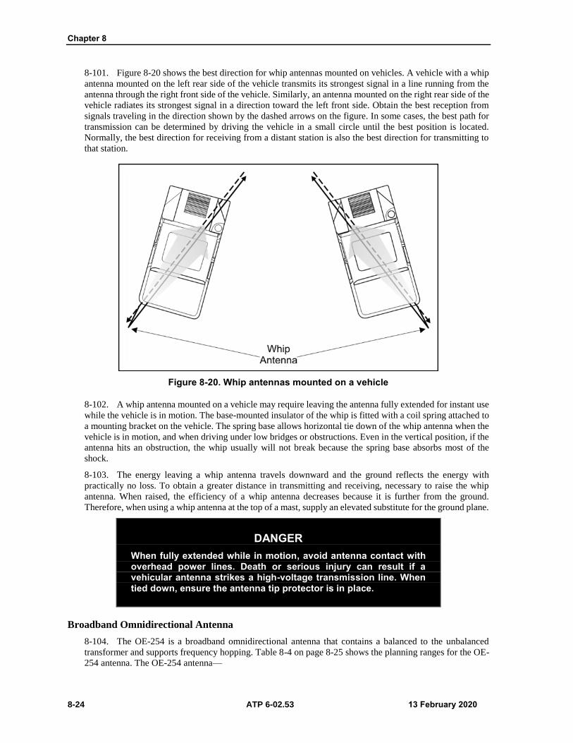
Chapter 8
8-24 ATP 6-02.53 13 February 2020
8-101. Figure 8-20 shows the best direction for whip antennas mounted on vehicles. A vehicle with a whip
antenna mounted on the left rear side of the vehicle transmits its strongest signal in a line running from the
antenna through the right front side of the vehicle. Similarly, an antenna mounted on the right rear side of the
vehicle radiates its strongest signal in a direction toward the left front side. Obtain the best reception from
signals traveling in the direction shown by the dashed arrows on the figure. In some cases, the best path for
transmission can be determined by driving the vehicle in a small circle until the best position is located.
Normally, the best direction for receiving from a distant station is also the best direction for transmitting to
that station.
Figure 8-20. Whip antennas mounted on a vehicle
8-102. A whip antenna mounted on a vehicle may require leaving the antenna fully extended for instant use
while the vehicle is in motion. The base-mounted insulator of the whip is fitted with a coil spring attached to
a mounting bracket on the vehicle. The spring base allows horizontal tie down of the whip antenna when the
vehicle is in motion, and when driving under low bridges or obstructions. Even in the vertical position, if the
antenna hits an obstruction, the whip usually will not break because the spring base absorbs most of the
shock.
8-103. The energy leaving a whip antenna travels downward and the ground reflects the energy with
practically no loss. To obtain a greater distance in transmitting and receiving, necessary to raise the whip
antenna. When raised, the efficiency of a whip antenna decreases because it is further from the ground.
Therefore, when using a whip antenna at the top of a mast, supply an elevated substitute for the ground plane.
DANGER
When fully extended while in motion, avoid antenna contact with overhead power lines. Death or serious injury can result if a vehicular antenna strikes a high-voltage transmission line. When tied down, ensure the antenna tip protector is in place.
Broadband Omnidirectional Antenna
8-104. The OE-254 is a broadband omnidirectional antenna that contains a balanced to the unbalanced
transformer and supports frequency hopping. Table 8-4 on page 8-25 shows the planning ranges for the OE-
254 antenna. The OE-254 antenna—

Antenna Techniques
13 February 2020 ATP 6-02.53 8-25
Operates in the 30–88 MHz range without any physical adjustments.
Has an input impedance of 50 ohms unbalanced with an average voltage standing wave ratio of
3:1 or less, at RF power levels up to 350 watts.
Capable of assembly and setup by one individual.
Meets the broadband and power handling requirements of the frequency hopping multiplexer
(FHMUX).
Table 8-4. OE-254 planning ranges
Terrain High Power Low Power (Nominal Conditions)
OE-254 to OE-254
Average Terrain 57.9 kilometers (36 miles)
19.3 kilometers (12 miles)
Difficult Terrain 48.3 kilometers (30 miles)
OE-254 to Vehicle Whip
Average Terrain 48.3 kilometers (30 miles)
12.9 kilometers (8 miles)
Difficult Terrain 40.3 kilometers (25 miles)
COM 201B Antenna
8-105. The COM 201B antenna is a commercial, VHF and UHF, vertically polarized, omnidirectional
antenna. Its unique design supports quick employment to support different applications. The COM 201B
antenna has a tripod leg structure that allows mounting the antenna directly on the ground or on a standard
communications mast. The COM 201B tripod legs provide the ground wave radiation of the signal
transmitted, and are necessary for proper operations. The COM 201B supports quick assembly and
disassembly for transport. This makes it ideal for situations where there is not enough time to erect an OE-
254 antenna.
Note. The COM 201B is not an Army-issued replacement for the OE-254 antenna.
8-106. The antennas ease of operations makes it ideal for use as a field expedient antenna or mounting to a
vehicle when requiring more elevation. The eye fitting at the top of the antenna facilitates suspending it from
buildings or trees when a mast is not available and when requiring more height.
8-107. The COM 201B antenna has the following characteristics and capabilities—
Operates in the 30–88 MHz range.
Vertically polarized.
Input impedance of 50 ohms unbalanced with an average voltage standing wave ratio of 2.5:1, at
RF power levels up to 200 watts.
Maximum power towards the horizon with a typical antenna gain of 0 dBi.
Does not require active tuning.
One individual can assemble and erect.
Assembly can be stored in a space less than 36 inches long by 10 inches in diameter.
Quick Erect Antenna Mast
8-108. The quick erect antenna mast, AB 1386/U is used for elevating tactical communications antennas to
a maximum height of 33 feet (10 meters) which results in more reliable communications over extended
ranges. The quick erect antenna mast uses the same antenna elements and RF cable as the OE-254 antenna.
The quick erect antenna mast mounts to the OE-254 and WIN-T antenna.

Chapter 8
8-26 ATP 6-02.53 13 February 2020
8-109. The mast can deploy and operate in a ground or vehicular (wheeled and tracked) mounted
configuration. The antenna erects in less than 8 minutes with 2 Soldiers and in 15 minutes with one Soldier.
VHF Half-Rhombic Antenna
8-110. The OE-303, VHF half-rhombic antenna is a vertically polarized antenna that, when used with VHF
FM tactical radios, extends the range of transmission considerably, and provides degrees of EP. The half-
rhombic antenna, when properly employed, decreases VHF FM radio susceptibility to hostile EW operations
and enhances the communications ranges of the deployed radio sets. This effect occurs by directing the
maximum signal strength in the direction of the desired friendly unit.
8-111. The VHF half-rhombic antenna is a high gain, lightweight, directional antenna. It operates over the
frequency range of 30–88 MHz. The antenna and ancillary equipment, guy wires, stakes, tools, and mast
sections fit in a carrying bag for manpack or vehicular transportation.
8-112. The planning range for the OE-303 is equivalent to the planning range of the OE-254. The OE-303
half rhombic antenna is used with the AB-1244 mast assembly, consisting of 12 tubular mast sections five
lower-mast sections, one mast transition adapter, five upper-mast sections, and antenna adapter, a mast base
assembly, and different ancillary equipment. Stabilization of the erected mast assembly occurs by a two-
level, four-way guying system. Figure 8-21 is an example of the OE-303 VHF half-rhombic antenna.
Figure 8-21. OE-303 half-rhombic VHF antenna
The OE-303 antenna handles RF power levels up to 200 watts. It matches nominal 50-ohm
impedance with a voltage standing wave ratio of no more than 2:1, over the entire frequency range
of the antenna.
The OE-303 half rhombic antenna has the following characteristics and capabilities—
Erected in a geographical area of 53.3 meters (175 feet) in diameter, or less, depending upon
the frequency.
Mounted on any structure approximately 15.2 meters 50 feet in height.
Azimuth directional change within 1 minute.
Transported by manpack or tactical vehicle when fitted into a package.
Operation with the four-port FHMUX.

Antenna Techniques
13 February 2020 ATP 6-02.53 8-27
8-113. The OE-303 half-rhombic antenna supports special applications and is a task assigned as required.
Its primary use is on command and intelligence networks to a higher headquarters. Units that habitually
operate over extended distances from parent units and special task units use the OE-303 half-rhombic
antenna.
High Frequency Antennas Usable at VHF and UHF
8-114. Simple vertical half-wave dipole doublet and quarter wave monopole antenna are very popular for
omnidirectional transmission and reception over short-range distances. For longer distances, typically use
rhombic antennas made of wire similar in design to HF versions to provide an advantage at frequencies as
high as 1 GHz.
8-115. The dipole doublet antenna also considered a center fed antenna is a half-wave antenna consisting
of two-quarter wavelength sections on each side of the center. Figure 8-22 is an example of the improvised
dipole doublet antenna used with FM radios.
Figure 8-22. Half-wave dipole (doublet) antenna
8-116. A transmission line conducts electrical energy from one point to another and transfers the output of
a transmitter to an antenna. It is possible to connect an antenna directly to a transmitter; the antenna generally
is located distances away. In a vehicular installation, for example, the antenna is mounted outside, and the
transmitter inside the vehicle.
8-117. Operators may use pieces of wood to support center-fed half-wave FM antennas. These antennas
rotate to any position to obtain the best performance. If the antenna is vertical, position the transmission line
horizontally from the antenna, for a distance equal to at least one-half of the antenna’s length, before dropping
down to the radio set.
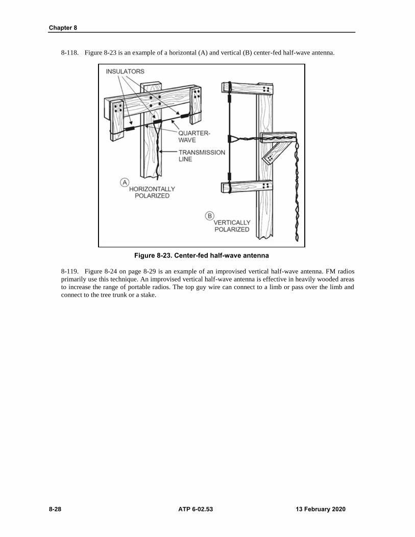
Chapter 8
8-28 ATP 6-02.53 13 February 2020
8-118. Figure 8-23 is an example of a horizontal (A) and vertical (B) center-fed half-wave antenna.
Figure 8-23. Center-fed half-wave antenna
8-119. Figure 8-24 on page 8-29 is an example of an improvised vertical half-wave antenna. FM radios
primarily use this technique. An improvised vertical half-wave antenna is effective in heavily wooded areas
to increase the range of portable radios. The top guy wire can connect to a limb or pass over the limb and
connect to the tree trunk or a stake.

Antenna Techniques
13 February 2020 ATP 6-02.53 8-29
Figure 8-24. Improvised vertical half-wave antenna
SATELLITE COMMUNICATIONS ANTENNAS
8-120. The most important consideration in addressing line of sight equipment is the antenna elevation with
respect to the path terrain. Choose sites that exploit natural elevations.
8-121. The most important consideration in siting over-the-horizon systems is the antenna horizon
screening angles at the terminals. As the horizon angle increases, the transmission loss increases, resulting in
a weaker signal.
8-122. The effect of the horizon on transmission loss is very significant. Except where the consideration of
one or more other factors outweighs the effect of horizon angles, the site with the most negative angle should
be the first choice. If no sites with negative angles exist, the site with the smallest positive angle should be
the first choice.
8-123. The horizon angle can be determined by using transit at each site and sighting along the circuit path.
The on-site survey determines the visual horizon angle. The radio horizon angle is slightly different from the
visual horizon angle: the difference is generally insignificant.

Chapter 8
8-30 ATP 6-02.53 13 February 2020
8-124. Measure the horizon angle between the tangent at the exact location of the antenna and a direct line
of sight to the horizon. The tangent line is a right angle 90 degrees to a plumb line at the antenna site. If the
line of sight to the horizon is below the tangent line, the horizon angel is negative.
8-125. Trees, building, hills, or the Earth can block a portion of the UHF signals, causing an obstruction
loss. To avoid signal loss due to obstruction and shielding required clearance between the direct line of sight
and the terrain, use path profile plots to determine if adequate clearance in line of sight systems.
8-126. SATCOM sets weaken or distort signals may result from operated near steel bridges, water towers,
power lines, or power units. The presence of congested air-traffic conditions on the proximity of microwave
equipment can result in significant signal fading.
8-127. For line of sight and TACSAT communications, the AN/PSC-5 family of radios is the most widely
used radios. The AN/PSC-5 provides a line of sight communications with the AS-3566 antenna and long-
range SATCOM with the AS-3567 and AS-3568 antennas. The AS-3566, AS-3567, and AS-3568 antennas
characteristics are as follows—
AS-3566, Low Gain Antenna.
Frequency range (line of sight): 30–400 MHz.
DAMA: 225–400 MHz.
Non DAMA: 225–400 MHz.
Polarization: directional.
Power capability: determined by terminating resistor.
Azimuth (bearing): directional.
AS-3567, Medium Gain Antenna.
Frequency range: 225–399.995 MHz.
Beamwidth: 85 degrees.
Orientation: Directional.
Elevation (0–90 degrees).
Input impedance: 50 ohms.
Voltage standing wave ratio: 1.5:1
Gain: 6 dB (225–318 MHz). 5 dB (318–399.995 MHz).
AS-3568, High Gain Antenna.
Frequency range: 240–400 MHz.
Beamwidth: 77 degrees.
Orientation: Directional.
Elevation: (0 to 90 degrees).
Azimuth: +180 degrees.
Input impedance: 50 ohms.
Voltage standing wave ratio: 1.5:1.
Gain: 8 dB (240–318 MHz) and 6 dB (318–400 MHz).
Power: up to 140 watts.
FIELD REPAIR
8-128. Antennas that are broken or damaged cause poor communications or even communications failure.
If a spare antenna is available, replace the damaged antenna. When a spare is not available, the user may have
to construct an emergency antenna. The following paragraphs provide recommendations on repairing
antennas and antenna supports.

Antenna Techniques
13 February 2020 ATP 6-02.53 8-31
REPAIR OF A WHIP ANTENNA
8-129. If a whip antenna is broken into two sections, temporarily repair the antenna by rejoining the
sections. Remove the paint and clean the sections to ensure a good electrical connection. Place the sections
together, secure them with a pole or branch, and lash them with bare wire or tape above and below the break
(see figure 8-25 antenna A).
8-130. For severely damaged whip antennas, use a length of field wire direct-1/TT the same length as the
original antenna. Remove the insulation from the lower end of the field wire antenna, twist the conductors
together, insert them in the antenna base connector, and secure with a wooden block. Use either a pole or a
tree to support the antenna wire (see figure 8-25, antenna B).
Figure 8-25. Field repair of broken whip antennas
WIRE ANTENNAS
8-131. Emergency repair of a wire antenna may involve the repair or replacement of the wire used as the
antenna or transmission line. It may also require the repair or replacement of the assembly used to support
the antenna. When one or more antenna wires are broken, reconnecting the broken wires can repair the
antenna. To do this, lower the antenna to the ground, clean the ends of the wires, and twist the wires together.
When possible, solder the connection and reassemble.
8-132. Damaged antenna supports may require using a substitute for the damaged support and if properly
insulated may consist of any material of adequate strength. Radiating elements not correctly insulated may
short field antennas to ground and be ineffective.
8-133. Operators may use many common items as expedient field insulators. Plastic or glass, including
plastic spoons, buttons, bottlenecks, and plastic bags is the best insulator. Wood and rope also act as
insulators, although they are less effective than plastic and glass. The radiating element, the actual antenna
wire, should only touch the antenna terminal, and physically separated from all other objects other than the
supporting insulator.
8-134. Figure 8-26 on page 8-32 is an example of field expedient antenna insulators.

Chapter 8
8-32 ATP 6-02.53 13 February 2020
Figure 8-26. Examples of field expedient antenna insulators
ANTENNA GUYS
8-135. Antenna guys stabilize the supports for an antenna. They usually made of wire, manila rope, or nylon
rope. Repair broken guy rope by tying the two broken ends together. If the rope is too short after completing
the tie, add another piece of rope or a piece of dry wood or cloth to lengthen it. Broken guy wire can replace
another piece of wire. To ensure that the guys made of wire do not affect the operation of the antenna, cut
the wire into several short lengths and connect the pieces with insulators. Figure 8-27 on page 8-33 shows an
example of repaired guy lines with wood.

Antenna Techniques
13 February 2020 ATP 6-02.53 8-33
Figure 8-27. Repaired antenna guy lines and masts
ANTENNA MASTS
8-136. Masts support antennas and if broken, replace the mast with another mast of the same length. When
long poles are not available as replacements, overlap and lash short poles together with rope or wire to provide
a pole of the required length.

This page intentionally left blank.

13 February 2020 ATP 6-02.53 9-1
Chapter 9
Tactical Radio Key Management Techniques
Key Management Infrastructure is a single, automated, network-accessible, electronic-
based key management system, and a predominantly electronic cryptographic product
delivery infrastructure. The chapter addresses key management techniques protecting
voice, data, and video information over tactical radio networks.
KEY MANAGEMENT INFRASTRUCTURE
9-1. Key management infrastructure (KMI) is a unified, scalable, interoperable, and trusted infrastructure
that provides net-centric key management services to systems that rely on cryptography while serving the
DOD and the broader cryptographic community. KMI builds on the foundation for a new automated
infrastructure to deliver key management products and services to support the warfighter. KMI provides the
foundation for key management in a general-purpose networking environment.
9-2. KMI automates the functions of key management, control, and distribution, EP generation and
distribution, signal operating instruction management. The commander appoints a KOAM to manage the
account. KOAMs oversee COMSEC policies and procedures to subordinate units and mitigate COMSEC
risk for the command.
9-3. The KMI account provides commanders the necessary tools to work with the widely proliferating
COMSEC systems associated with the WIN-T, JTIDS, SINCGARS, and other keying methods, electronic
key generation, over-the-air rekeying, and electronic bulk encryption and transfer fielded by the Army.
9-4. The KMI hardware and software provide communications planners the ability to design, develop,
generate, distribute, and manage decentralized and automated communications-electronics operating
instructions and signal operating instructions. The KOAM produces the EP fill variables to support
SINCGARS in electronic formats. The KMI software also produces signal operating instructions in either
electronic or hard copy format. The objective is to use the SKL to eliminate the need for hard copy signal
operating instructions.
9-5. COMSEC planning and key distribution are essential to the success of military operations and are a
command responsibility. The controlling authority is the commander, who establishes a cryptographic
network. Within divisions, brigades, and battalions, commanders may delegate authority and responsibilities
depending upon command policy and operational situations.
9-6. Units at corps and division levels and separate brigades with authorized KMI hardware and software
can design, develop, generate, and distribute communications-electronics operating instructions and
SINCGARS frequency hopping data, and with HF, UHF, and VHF frequency assignments at their respective
levels and subordinate levels, as appropriate.
9-7. Brigades and separate battalion units use KMI capable devices or components to distribute generated
communications-electronics operating instructions and SINCGARS frequency hopping data for use at their
respective and subordinate levels.
Note. Refer to AR 380-40, AR 380-5, AR 25-2, and AR 380-53 for additional information on
controlling authority and commanders’ responsibilities regarding cryptographic networks.

Chapter 9
9-2 ATP 6-02.53 13 February 2020
KEY DISTRIBUTION
9-8. Key distribution is critical in achieving secure transmissions. Commanders ensure the establishment
of these procedures in the unit’s standard operating procedure. The KOAM is responsible for the brigade
COMSEC account. The property book officer provides logistical support for the control and distribution of
internal brigade and subordinate battalion COMSEC material using the Information Systems Security
Program.
9-9. The representative authorized to order keys is the requesting unit’s KOAM, with a valid COMSEC
account, with a requirement. TB 380-41 provides more information on the procedures for safeguarding,
accounting, supply control, and distribution of COMSEC material.
JOINT COMMUNICATIONS SECURITY KEY DISTRIBUTION
9-10. A joint contingency force, corps, and division key management plan provide guidance on the
COMSEC key distribution; it does not change current unit procedures. The KOAM is responsible for key
management plan coordination, and the spectrum manager is responsible for the satellite access request. The
KOAM and spectrum manager need to ensure prior coordination between the two to identify all requests for
COMSEC from all units.
ORDERWIRE KEY DISTRIBUTION
9-11. The DAMA key management plan provides guidance on obtaining orderwire keys using the KMI with
the DAMA control system. It also provides instructions for the receipt of over-the-air rekeying by the users.
The Spitfire provides an over-the-air rekeying capability for orderwire keys. Spitfire operators should have
the current and next orderwire keys for each footprint in which they operate.
Note. Only the requesting unit’s KOAM with a valid COMSEC account can order these keys.
(Refer to TB 380-41.)
9-12. The DAMA key management plan provides guidance on obtaining orderwire keys using KMI with the
DAMA control system. It also provides instructions for the receipt of over-the-air rekeying by the users. The
Spitfire provides an over-the-air rekeying capability for orderwire keys. Spitfire operators should have the
current and next orderwire keys for each footprint in which they operate.
MANAGEMENT CLIENT
9-13. The Management Client (MGC) is a component of the KMI that provides management of COMSEC
material both physical and electronic. This component interfaces with the advanced key processor assigned
to distribute keys. Using this platform provides local real-time electronic key generation, distribution, and
management to support the mission at all Army command levels that have a COMSEC account. The lowest
command level that has a COMSEC account is the brigade. The battalion may have a COMSEC account
depending on unit design and real-world mission requirements. Tandem use of the management client and
advanced key processor enables the KOAM to—
Order and account for all forms of COMSEC material.
Store key in encrypted form.
Perform key generation and automatic key distribution.
Perform COMSEC material accounting functions.
Communicate directly with other KMI accounts.
AUTOMATED COMMUNICATIONS ENGINEERING SOFTWARE
9-14. Automated Communications Engineering Software (ACES) is a network planning software program
that plans, creates, distributes, manages, and verifies cryptonets and key related information. ACES allow
users to perform fully automated cryptographic network, signal operating instructions, communications-

Tactical Radio Key Management Techniques
13 February 2020 ATP 6-02.53 9-3
electronics operating instructions, joint communications-electronics operating instructions and EP planning,
management, validation and generation distribution at the time and location needed.
9-15. The network planning functionality of ACES incorporates cryptonet planning, key management, and
key tag generation. The planning concept relates to the development of network structures supporting
missions and plans. The data for a given plan includes individual networks, which are assigned individual
network members. Designated network members define the platforms, specific equipment fill locations, and
associate key tags and keys with the equipment locations.
9-16. Network members then download the equipment records, which include platform data, network data,
and key tags associating the data with the required key. Similarly, the EP data and signal operating
instructions generated by the ACES workstation operator enables the data download to the SKL.
COMBAT NET RADIO MODULE
9-17. The combat net radio planning module provides the necessary functions and procedures to create and
modify hopsets, loadsets, and to generate SINCGARS transmission security keys. It also provides the
capability to plan combat net radio networks in all bands. Combat net radio network planning integrates with
the master net list module.
RESOURCE MANAGER MODULE
9-18. The resource manager module contains imported frequency resources. The resource manager module
allows using resources to create, edit, merge, delete, and print resources. The resource manager also provides
the planner with the ability to import and export resources in ACES, integrated system control, and standard
frequency action format formats. Resource managers coordinate frequency resources are for specific garrison
installations and training areas. Authorization for using frequency resources outside of the continental United
States and its possessions are under guidance outlined in strategic agreements and established channels for
coordination. Spectrum managers should contact organizational, theater army or geographic combatant
command spectrum management offices for additional information.
SIGNAL OPERATING INSTRUCTIONS MODULE
9-19. The signal operating instructions module allows the creation of editions and updates. Signal operating
instructions is a series of orders issued to control and coordination of the signal operations of a command or
activity. It provides the guidance needed to ensure the speed, simplicity, and security of communications.
Net selection occurs from the master net list included in a generated signal operating instructions edition.
Before signal operating instructions generation, save and validate the master net list.
MASTER NET LIST MODULE
9-20. The master net list maintains all networks requiring signal operating instructions assignments.
Networks created from the master net list or imported have editing potential, which allows tracking of
individual frequency assignments with assigned equipment. The ACES version of the master net list has a
direct correlation to standard frequency action format line item numbers.
9-21. The master net list is the database link for all information listed under a plan, as networks, frequencies,
and equipment. The master net list provides the ability to create, edit, organize, and delete networks. Before
creating the master net list, the ACES workstation operator identifies the number of networks required, types
of equipment used, and equipment specifications, as maximum transmit power, frequency bands, and
emission designators.
9-22. The master net list module of the ACES software also displays in joint or Service-specific views. The
master net list also incorporates several standard frequency action format compatible fields to facilitate the
transfer of data to and from other frequency management systems such as Spectrum XXI, including Service
specific systems. The database capabilities of the ACES workstation allow the data in the master net list to
create the initial standard frequency action format proposal and the signal operating instructions.

Chapter 9
9-4 ATP 6-02.53 13 February 2020
9-23. The software components on the ACES workstation include the ACES core module, general-purpose
module, combat net radio module, resource manager module, signal operating instructions module master
net list module.
COMMUNICATIONS-ELECTRONICS OPERATING INSTRUCTIONS AND SIGNAL OPERATING
INSTRUCTIONS DEVELOPMENT
9-24. The Military Communications Electronics Board has designated ACES as the Joint Spectrum
Management Planning software. ACES helps the production of the communications-electronics operating
instruction and signal operating instructions generation. Building an initial Master Net List to support first-
time generation takes four to seven days. The hopset provides frequency resources for the loadset. The TSK
determines the frequency hop pattern for the radio. ACES can generate division-size communication-
electronics operating instructions and signal operating instructions in two to five hours.
9-25. ACES automates the generation process, the signal officer, communications chief, and frequency
manager initially design the communications-electronics operating instructions and signal operating
instructions on paper. Table 9-1 lists the initial steps for designing and developing communications-
electronics operating instructions and signal operating instructions data. The following paragraphs provide
more detail on communications-electronics operating instructions and signal operating instructions
development.
Table 9-1. Initializing Automated Communications Engineering Software or communications-electronics operating instructions and signal operating instructions data
Step Description
1 Research and extract data from the modified table of organization and equipment, which authorizes using personnel and equipment.
2 Determine the doctrine to be followed.
3 Operation order, operation plan, or unit standard operating procedure.
4 Frequency list from the spectrum manager.
5 Determine how many networks and frequencies are required. Use the current communications-electronics operating instructions and signal operating instructions as a starting point.
LOADSETS
9-26. The G-6 (S-6) section identifies requirements for the construction of loadsets to support the radios that
their organization employs. Once defined, the frequency manager constructs the loadsets using ACES, saves
the loadsets to file, and distributes the loadsets to subordinate organizational units or elements for follow-on
distribution to respective users.
9-27. For example, the commander of an infantry battalion would typically be a member of several
frequencies hopping SINCGARS networks. One of the commander’s SINCGARS could be preset to operate
in the following nets—
Brigade command network.
Brigade operations network.
Battalion command network.
Battalion operations network.
Brigade RETRANS network.
9-28. Radio operators typically load all six preset channels on the SINCGARS, with operational network
identifiers and TEKs. If a requirement to perform over-the-air rekeying arises, all stations involved with an
over-the-air rekeying load a KEK into preset Channel 6 on the SINCGARS, with an appropriate network
identifier.

Tactical Radio Key Management Techniques
13 February 2020 ATP 6-02.53 9-5
LOADSET UPDATES
9-29. The responsible signal section personnel using ACES and revised loadset software, as appropriate,
maintain loadset data. Update loadset data with new replacement key data before the current key expires. The
loadset data is then saved to file, and distributed to users via SKL, to ensure they are in place and available
for loading into the SINCGARS at the appropriate key changeover time. The signal sections should have
several sets of loadsets with associated keys, already constructed and distributed (or available for expeditious
distribution) for immediate use.
LOADSET REVISIONS AND CREATIONS
9-30. Existing loadsets may require revision when the required network content changes, unit reassignment
or attachment. New loadsets may require construction to meet new requirements and create a new task force
organization.
JOINT COMMUNICATIONS ELECTRONICS OPERATING INSTRUCTIONS SYSTEM
9-31. The Joint Automated Communications Electronics Operating Instructions System has the same
primary function as ACES. The Joint Automated Communications Electronics Operating Instructions System
interfaces between the joint communications-electronics operating instructions generation tool with service
specific communications planning software and spectrum management automated tools.
9-32. The joint communications-electronics operating instruction is the primary controlling document for
single-channel radio communications in joint operations and exercises. The joint communications-electronics
operating instruction provides radio information for joint forces, Service-specific elements, and units
including—
Daily changing and non-changing frequency assignments.
SINCGARS cue, manual and net identification assignments.
Call sign assignments.
Call word assignments.
Daily changing code words.
SIMPLE KEY LOADER
9-33. The SKL AN/PYQ-10 is a handheld digital computer running the Windows operating system, core
library, and SKL user application software. The SKL interfaces with the KMI, ACES, and any end
cryptographic unit (ECU) that requires COMSEC key and data. The SKL integrates the functions of—
COMSEC key management.
Distribution.
EP management.
Signal operating instructions management.
Benign fill.
Other specialized capabilities into one comprehensive system.
9-34. The hardware platform that hosts the SKL software including the Secure Library is a vendor-supplied
ruggedized personal digital assistant device equipped with a KOV-21 Personal Computer Memory Card
International Association card. The SKL has no hard drive, so all programs are stored in non-volatile flash
memory.
9-35. The KOV-21 provides type 1 encryption and decryption services and provides a secure interface
between the host computer and interfacing devices. The SKL uses an embedded KOV-21 approach. The NSA
requires using a cryptographic ignition key to lock and unlock the KOV-21 information security card.
9-36. The cryptographic ignition key is a separate, removable, non-volatile memory device designed to
protect internal SKL keys and data from physical compromise when the SKL is in an unattended, non-secured
environment. Removal of the cryptographic ignition key from the SKL prevents the KOV-21 card from

Chapter 9
9-6 ATP 6-02.53 13 February 2020
unlocking. This results in denied access to the data. The absence of the cryptographic ignition key precludes
using SKL operations.

13 February 2020 ATP 6-02.53 10-1
Chapter 10
Electronic Warfare and Protection Techniques
This chapter addresses electronic warfare and the electronic protection techniques used
to prevent enemy jamming and intrusion into friendly communications systems. It also
discusses electronic protection responsibilities; communications services planning,
signal security, emission control, preventive and remedial electronic protection
techniques and the joint spectrum interference resolution reporting procedures and
requirements.
ELECTRONIC WARFARE
10-1. Electronic warfare is military action involving the use of electromagnetic and directed energy to
control the electromagnetic spectrum or to attack the enemy (JP 3-13.1). EW uses electromagnetic energy to
determine, exploit, reduce, or prevent hostile use of the electromagnetic spectrum; it also involves actions
taken to retain friendly use of the electromagnetic spectrum. EW consists of three divisions that have a unique
role in supporting unified land operations. The divisions of electronic warfare are—
Electronic warfare support (ES).
Electronic attack (EA).
EP.
10-2. Electronic warfare support is the division of electronic warfare involving actions tasked by, or under
direct control of, an operational commander to search for, intercept, identify, and locate or localize sources
of intentional and unintentional radiated electromagnetic energy for the purpose of immediate threat
recognition, targeting, planning, and conduct of future operations (JP 3-13.1).
10-3. ES provides the information required to combat threat electronic countermeasures, including threat
detection, warning, avoidance, target location, and homing. It also provides targeting information for
electronic or physical attack, and produces measurement and signals intelligence.
10-4. Electronic attack is the division of electronic warfare involving the use of electromagnetic energy,
directed energy, or antiradiation weapons to attack personnel, facilities, or equipment with the intent of
degrading, neutralizing, or destroying enemy combat capability and is considered a form of fires (JP 3-13.1)
10-5. EA includes actions taken to prevent or reduce the enemy’s effective use of frequencies, including
jamming and deception. EA employs weapons that use either electromagnetic or directed energy as their
primary destructive mechanism (lasers, RF weapons, and particle beams).
10-6. Electronic protection is the division of electronic warfare involving actions taken to protect personnel,
facilities, and equipment from any effects of friendly or enemy use of the electromagnetic spectrum that
degrade, neutralize or destroy friendly combat capability friendly combat capability (JP 3-13.1).
10-7. EP ensures friendly effective use of frequencies, despite the enemy’s use of electronic warfare. EP
measures include—
Careful siting of radio equipment.
Employment of directional antennas.
Operations using the lowest power required.
Staying off the air unless necessary.
Using a random schedule.
Using good radio techniques and continued operation.

Chapter 10
10-2 ATP 6-02.53 13 February 2020
ELECTRONIC WARFARE WHEN ATTACKING ENEMY COMMAND AND CONTROL NODES
10-8. EW contributes to the success of information operations by using offensive and defensive tactics and
techniques in a variety of combinations to shape, disrupt, and exploit adversarial use of the electromagnetic
spectrum while protecting friendly freedom of action. ES, as combat information, can provide real-time
information required for locating and identifying enemy command and control nodes, and for supporting
early warning and offensive systems during attack missions on enemy command and control capabilities.
Signals intelligence elements in support of EW provide timely information about an enemy’s
communications capabilities and limitations. The additional information received updates previously known
information about the enemy’s command and control capabilities. This updated information plans enemy
command, control attack operations, provide damage assessment feedback on the effectiveness of the overall
warfare plan for the enemy command and control attack operations.
10-9. EA is present in most enemy command and control attack operations in a combat environment. It
includes jamming and electromagnetic deception or destruction of enemy command and control nodes, with
directed-energy weapons or anti-radiation missiles.
10-10. EP protects the electromagnetic spectrum for friendly forces. Coordinating using the electromagnetic
spectrum through the joint restricted frequency list is a means of preventing fratricide between friendly
electronic emissions. Equipment and procedures designed to avoid enemy disruption or exploitation of the
electromagnetic spectrum are the best things friendly forces use their uninterrupted use of the electromagnetic
spectrum during enemy command and control attack operations. In combat, EP includes, but is not limited
to, the application of good training and sound procedures for countering enemy EA. U.S. forces (operators,
users, and planners) must understand the threat situation and the vulnerability of electronic equipment to
enemy EA efforts and take appropriate actions to safeguard equipment from attack. EP minimizes an enemy’s
opportunity for successful ES and EA against U.S. forces. For more information on joint EW, refer to
JP 3-13.1. For more information on joint electromagnetic spectrum management operations in the
electromagnetic operational environment, refer to CJCSM 3320.01C. For information on policy and
procedures for the management and use of the electromagnetic spectrum, refer to DODI 4650.01.
ELECTRONIC WARFARE WHEN PROTECTING FRIENDLY COMMAND NODES
10-11. EW can also contribute to friendly command node protection efforts by monitor an impending
enemy attack on friendly command nodes. ES is a common task between EW and signals intelligence that
can be actioned from EW assets or intelligence data. EW supports signals security monitoring to identify
potential sources of information for an enemy to obtain knowledge about friendly information systems.
10-12. To defend friendly force command nodes from enemy attack, exercise EP measures to safeguard
friendly forces from exploitation by enemy ES and signals intelligence operations. Frequency management
using the joint restricted frequency list is an essential defense measure against attack operations on command
nodes by the enemy.
ENEMY ATTACK ON FRIENDLY COMMAND NODES
10-13. Understanding the threat to the electromagnetic spectrum is the key to practicing sound EP
techniques. An enemy attack on friendly command nodes encompasses the integration of EW and physical
destruction of resources, to deny friendly forces electronic control systems. Potential adversaries consider
the attack on friendly command nodes integral to all combat operations. They have invested in developing
techniques and equipment to deny their enemies the effective use of the electromagnetic spectrum for
communications.
10-14. The enemy attack on friendly command nodes disrupts or destroys at least 60 percent of the
information, intelligence, and weapons systems communications, 30 percent by jamming and 30 percent by
destructive fires. When accomplishing this goal, enemy forces expend considerable resources gathering
combat information about their enemies. As locations are determined, and units identified, enemy forces
establish priorities to—
Jam communications assets.
Deceptively enter radio networks.

Electronic Warfare and Protection Techniques
13 February 2020 ATP 6-02.53 10-3
Interfere with the normal flow of their enemy’s communications.
ELECTRONIC PROTECTION RESPONSIBILITIES
COMMANDER
10-15. EP is a command responsibility. The more emphasis the commander places on EP, the greater the
benefits, regarding casualty reduction and combat survivability, in a hostile environment. Commanders at all
levels ensure the training of their ability to practice sound EP techniques.
10-16. Commanders continually measure the effectiveness of the EP techniques; they also consider EP
while planning tactical operations. Commanders’ EP responsibilities are—
Review all after action reports for jamming or deception, and assess the effectiveness of defensive
EP.
Ensure the G-6 (S-6) and the assistant chief of staff, intelligence (G-2), and the battalion or brigade
intelligence staff officer (S-2) report and adequately analyze all encounters of electromagnetic
interference, deception, or jamming.
Analyze how enemy efforts to disrupt or destroy friendly communications systems on friendly
operation plans.
10-17. Ensure the unit exercise COMSEC techniques daily. Units should—
Change network call signs and frequencies often the signal operating instructions.
Use approved encryption systems, codes, and authentication systems.
Control emissions.
Make EP equipment requirements known through quick reaction capabilities designed to expedite
procedure for solving, research, development, procurement, testing, evaluation, installations
modification, and logistics problems as they pertain to EW.
Ensure quick repair of radios with mechanical or electrical faults; this is one way to reduce radio-
distinguishing characteristics.
Practice network discipline.
STAFF
10-18. The organized staff assists the commander in accomplishing mission requirements. Specifically, the
staff responds immediately to the commander and subordinate units. The staff should—
Keep the commander informed.
Reduce the time to control, integrate and coordinate operations.
Reduce the chance for error.
10-19. All staff officers provide information, furnish estimates, and provide recommendations to the
commander; prepare plans and orders for military operations, and supervise subordinates to achieve mission
accomplishment. Staff members should help the commander carrying out communications EP
responsibilities. Staff officers’ responsibilities are—
G-2 (S-2) Staff. Advises the commander of enemy capabilities that deny the effective unit use of
the electromagnetic spectrum. They also keep the commander informed of the unit’s signal
security posture.
Operations Staff. Exercise staff responsibility for EP, ES, and EA scenarios in command post
and field training exercises, and evaluate EP techniques employed. The operations staff also
include EP in the unit training program.

Chapter 10
10-4 ATP 6-02.53 13 February 2020
G-6 (S-6) Staff—
Assists the cyber electronic warfare officer with the preparation of the EP policy.
Plans alternate means of communications for those systems most vulnerable to enemy
jamming.
Ensures distribution of available COMSEC equipment to those systems most vulnerable to
enemy information-gathering activities and ensures measures taken to protect critical friendly
frequencies from intentional and unintentional electromagnetic interference.
Enforces proper use of radio, EP, emission control, and TRANSEC procedures on
communications channels.
Performs frequency management duties, and issues signal operating instructions on a timely
basis.
Prepares and maintains a restricted frequency list of taboo, protected, and guarded
frequencies.
Prepares the EP and restricted frequency list appendixes to the signal annex with appropriate
cross-references to the other annexes EW, operations security, and deception to the signal
operating instructions for related information.
Participates in the CEMA working group to deconflict friendly EMS requirements with EW
activities and information collection efforts, compiles information, and distributes the JRFL.
Cyber electronic warfare officer. As a member of the operations staff, the cyber electronic
warfare officer plans, coordinates, and supports the execution of EW and other cyber
electromagnetic activities. The cyber electronic warfare officer integrates efforts across the
warfighting functions to ensure EW operations support the commander’s objectives. The cyber
electronic warfare officer—
Leads the EW working group.
Plans, coordinates and assesses EA, EP, and ES requirements.
Supports the G-2 (S-2) during the intelligence preparation of the battlefield process.
Provides information collection requirements to the G-2 (S-2) to support the assessment of
EW.
Supports the fire support coordinator to ensure the integration of EA with all other effects.
Provides EW support derived from tactical targeting information to the fire support
coordinator.
Coordinates with the G-6 (S-6) to plan, assess, and implement friendly EP measures.
Prioritizes EW effects and targets with the fire support coordinator.
Plans and coordinates EW operations across functional and integrating cells.
Deconflicts EW operations with the spectrum manager in the Cyber Electromagnetic Activity
element.
Maintains a current assessment of available EW resources.
Participates in other cells and working groups as required to ensure EW integration.
Coordinates with servicing judge advocate to ensure compliance with rules of engagement.
Serves as the Jamming Control Authority (JCA) for EW operations as directed by the
commander.
Prepares submits for approval and supervises the issuing and implementation of fragmentary
orders for EW operations.
Works with the G-2 (S-2) staff to synchronize and deconflict EW operations with intelligence
collection activities.
10-20. Electronic warfare capabilities are critical to maintaining communications in a hostile
electromagnetic operational environment. Refer to ATP 3-12.3 for more information about electronic
warfare.

Electronic Warfare and Protection Techniques
13 February 2020 ATP 6-02.53 10-5
COMMUNICATIONS PLANNING PROCESS
10-21. Planning counters the enemy’s attempts to take advantage of the vulnerabilities of friendly
communications systems. Planning counters the enemy’s attempts to take advantage of the vulnerabilities of
friendly communications systems. At a minimum, planners should consider the following four categories of
EP planning: deployment, employment, replacement, and concealment.
COMMUNICATIONS PLANNING
10-22. When conducting communications planning, use spectrum management tools to enable
electromagnetic spectrum planning and to define and support requirements. Coordinate all frequency use
before activation of emitters to mitigate or eliminate electromagnetic interference or other negligible effects.
Consider the following when conducting electromagnetic spectrum management planning—
Transmitter and receiver locations.
Antenna technical parameters and characteristics.
Number of frequencies desired and separation requirements.
Nature of the operation (fixed, mobile land, mobile aeronautical, and over water or maritime).
Physical effects of the operational environment ground, soil, humidity, and topology.
All electromagnetic spectrum-dependent equipment includes emitters, sensors, and unmanned
aerial sensors.
Start and end dates for use.
CONTROL OF COMPROMISING EMANATIONS
10-23. Radios can create a significant vulnerability control of compromising emanations if TEMPEST
installation guidelines not followed. Radios with embedded cryptographic devices should be installed and
operate any applicable operations security doctrine for that device or radio. The TEMPEST countermeasure
review for a facility, platform, or system may set additional countermeasure requirements for radios operating
in those environments. Compliance with all TEMPEST requirements is critical for the protection of classified
information. Refer to AR 380-27 for more information about control of compromising emanations. The
supporting certified TEMPEST technical authority can provide guidance on countermeasure compliance.
PRIMARY, ALTERNATE, CONTINGENCY, AND EMERGENCY COMMUNICATION PLAN
10-24. The primary, alternate, contingency, and emergency (PACE) communication plan is a
communication plan for a specific mission or task, not a specific unit. The plan considers both intra- and
inter-unit sharing of information. The PACE plan designates the order in which an element will move through
available communications systems until establishing contact with the desired distant element.
10-25. The G-6 (S-6) develops a PACE plan for each phase of an operation to ensure that the commander
can maintain command and control of the formation. The plan reflects the training, equipment status, and
actual capabilities of the formation. Higher headquarters evaluate communication requirements with
subordinate echelons and work with the G-6 (S-6) to develop an effective plan. Upon receipt of an order from
a higher headquarters, the receiving unit evaluates the PACE plan for two essential elements—
Availability of assets to execute the plan to higher.
Ability to nest with the higher command’s PACE plan.
10-26. Viable PACE plans are crucial to the commander’s situational awareness. A subordinate unit,
untrained on a communications system or lacks the subcomponents to make the system mission capable does
not ensure continuity of command and control by including the communications system in the PACE plan.
Commanders’ ability to exercise command and control during an operation can suffer due to communications
systems that are in transit or otherwise unavailable. If a unit does not have four viable methods of
communication, it is appropriate to issue a PACE plan with only two or three systems listed.
10-27. If the unit cannot execute the full PACE plan to its higher command, it must inform the issuing
headquarters with an assessment of shortfalls, gaps, and possible mitigation measures as part of mission
analysis during the military decision-making process. During course of action development, the S-6 nests the

Chapter 10
10-6 ATP 6-02.53 13 February 2020
signal support plan with the higher command’s plan whenever practical. This aids in maintaining continuity
of effort.
10-28. If a higher command places any form of information requirement on one or more of its subordinate
units, subordinate units address the requirement as follows:
Generate an executable PACE plan.
Include the PACE plan in the operation order or fragmentary order when published.
Publish the data requirement in the base operation order or fragmentary order execution paragraph
in the tasks section of the order including a reference to the specific annex for detailed format and
PACE.
GEOMETRY
10-29. Planners analyze the terrain and determine methods to make the geometry of the operations work in
favor of friendly forces. Adhering rigidly to standard command post deployment makes it easier for the
enemy to use direction finding to aim jamming equipment at friendly radios.
10-30. Deploying units and communications systems perpendicular to the forward line of own troops
enhance the enemy’s ability to intercept communication because U.S. forces aim transmissions in the
enemy’s direction. When possible, friendly forces install terrestrial line of sight communications links
parallel to the forward line of own troops. This supports keeping the primary strength of U.S. transmissions
in friendly terrain.
10-31. Single-channel TACSAT systems reduce friendly command post vulnerability to enemy direction
efforts. Tactical SATCOM is inherently resistant to enemy direction finding. When possible, use terrain
features to mask friendly communication from enemy positions. This may require moving senior
headquarters farther forward and using more jump or tactical command posts to ensure that commanders can
continue to direct their units effectively.
10-32. Selecting command post locations requires careful planning as command post locations generally
determine antenna locations. The proper installation and positioning of antennas around command posts are
critical. Disperse and position antennas and emitters at the maximum remote distance and terrain dependent
from the command post to ensure that not all of a unit’s transmissions are coming from one central location
system design.
10-33. Establish alternate routes of communication when designing communications systems. This involves
establishing enough communications paths to ensure that the loss of one or more routes does not severely
degrade the overall system. The commander establishes the priorities of critical communications links.
Provide high priority links with the most significant number of alternate routes.
10-34. Alternate routes enable friendly units to continue to communicate despite the enemy’s efforts to
deny them communication systems. Alternate routes also transmit false messages and orders on the route
experiencing electromagnetic interference, while they transmit actual messages and orders through another
route or means. A definite benefit of continuing to operate in a degraded system is the probability the enemy
will waste efforts to impair friendly communications elsewhere.
10-35. Three routing concepts, or variation of them, can be used in communications—
Straight-line system. Provides no alternate routes of communications.
Circular system. Provides one alternate route of communications.
Grid system. Provides as many alternate routes of communications as can be practically planned.
10-36. Avoid establishing a pattern of communication. Enemy intelligence analysts may be able to extract
information from the design, and the text, of friendly transmissions. If easily identifiable patterns of friendly
established communication, the enemy can gain valuable information.
10-37. The number of friendly transmissions tends to increase or decrease according to the type of tactical
operations executed. Execute this deceptive communication traffic by using false peaks, or traffic leveling.
False peaks to prevent the enemy from connecting an increase of communications with a tactical operation.
Transmission increases on a random schedule create false peaks.

Electronic Warfare and Protection Techniques
13 February 2020 ATP 6-02.53 10-7
10-38. Tactically accomplish traffic leveling by designing messages to transmit when a decrease in
transmission traffic. Traffic leveling keeps the transmission traffic constant. Coordinate messages transmitted
for traffic leveling or false peaks to avoid operational security violations, electromagnetic interference, and
confusion among friendly equipment operators.
10-39. ACES equipment, software, and subsequent signal operating instructions development resolve many
problems concerning communications patterns; they allow users to change frequencies often, and at random.
This is an important aspect of confusing enemy traffic analysts. Enemy traffic analysts are confused when
frequencies, network call signs, locations, and operators often change. The enemy uses U.S. tactics,
techniques, and procedures to help perform their mission. These procedures require flexibility to avoid
establishing communications patterns.
REPLACEMENT
10-40. Replacement involves establishing alternate routes and means of doing what the commander
requires. FM voice communications are the most critical communications used by the commander during
enemy engagements and require reserving critical systems for critical operations.
10-41. Use alternate means of communication before enemy engagements. This ensures the enemy cannot
establish a database to destroy primary means of communication. If the primary means degrades, replace
primary systems with alternate methods of communication. Replacements require preplanning and careful
coordination; if not, compromise of the alternative means of communication occurs and is no longer use as
the primary means of communication. Users of communications equipment require knowledge of how and
when to use the primary and alternate means of communication. This planning and expertise ensure the most
efficient use of communications systems.
CONCEALMENT
10-42. Operation plans should include provisions to conceal communications personnel, equipment, and
transmissions. It is difficult to conceal most communications systems; installing antennas as low as possible
on the backside of terrain features, and behind manmade obstacles, helps conceal communications equipment
while still permitting communication.
SIGNAL SECURITY
10-43. EP and signal security are closely related. They are defensive arts based on the same principle. If
adversaries do not have access to the essential elements of friendly information of U.S. forces, they are much
less effective. The purpose of practicing sound EP techniques is to ensure the continued effective use of the
electromagnetic spectrum. The goal of signal security is to ensure the enemy cannot exploit the friendly use
of the electromagnetic spectrum for communication. Signal security techniques are designed to give
commanders confidence in the security of their transmissions. Plan signal security and EP based on the
enemy’s ability to gather intelligence and degrade friendly communications systems.
10-44. Tactical commanders ensure effective employment of all communications equipment, despite the
enemy’s concerted efforts to degrade friendly communication to gain a tactical advantage. Modifying and
developing equipment, to make friendly communication less susceptible to enemy exploitation is an
expensive process. Equipment that solves EP problems is being developed and fielded. Ultimately, the
commander, staff planners, and radio operators are responsible for the security and continued operation of
communications equipment.
EMISSION CONTROL
10-45. The control of friendly electromagnetic emissions is essential to successfully defend against enemy
attempts to destroy or disrupt U.S. communications. Emission control is the selective and controlled use of
electromagnetic, acoustic, or other emitters to optimize command and control capabilities while minimizing,
for operations security: a. detection by enemy sensors; b. mutual interference among friendly systems; and/or
c. enemy interference with the ability to execute a military deception plan (JP 3-13.1). When operating radios,
exercise emission control at all times. Only turn transmitters when needed to accomplish the mission. Enemy

Chapter 10
10-8 ATP 6-02.53 13 February 2020
intelligence analysts look for patterns they can turn into valuable information. Inactive friendly transmitters
do not provide the enemy with usable intelligence. Emission control can be total; for example, the commander
may direct radio silence whenever desired. Radio silence is the status on a radio network in which all
stations are directed to continuously monitor without transmitting, except under established criteria.
10-46. Keep power output to a minimum and keep transmissions to a minimum of 20 seconds absolute
maximum, 15 seconds maximum preferred and should contain only mission-critical information. Good
emission control makes using communications equipment appear random and is consistent with good EP
practices. This technique alone will not eliminate the enemy’s ability to find a friendly transmitter; but when
combined with other EP techniques, it makes locating a transmitter more difficult.
PREVENTIVE ELECTRONIC PROTECTION TECHNIQUES
10-47. In planning communications, consider the enemy’s capabilities to deny the effective use of
communications equipment. EP techniques also force enemies to doubt the effectiveness of their jamming
and deception efforts. Radio operators use preventive EP techniques to safeguard friendly communications
from enemy disruption and destruction. Preventive EP techniques include all measures taken to avoid enemy
detection and to deny enemy intelligence analysts useful information. These techniques include EP designed
circuit equipment features and radio systems installation and operating procedures. Refer to AR 380-5 for
the Department of the Army information security program.
10-48. EP designed circuits focus on technology enhancements, to mitigate the effects of enemy radio
electronic combat threats and reduce vulnerabilities to electronic countermeasures.
10-49. Radio operators have little control over the effectiveness of EP designed circuits; therefore, their
primary focus is radio systems installation and operating procedures. Appendix C addresses operations in
cold weather, jungle, urban, desert, and nuclear environments.
10-50. Incorrect operating procedures can jeopardize the unit’s mission and ultimately increase unit
casualties. Communications equipment operators require the instinctive use of preventive and remedial EP
techniques. Maintenance personnel require knowledge that improper modifications to equipment may cause
the equipment to develop peculiar characteristics readily identifiable by the enemy. Commanders and staff
develop plans to ensure the continued use of friendly communications equipment and systems, while also
evaluating joint spectrum interference resolution (JSIR) reports and after-action reports to initiate appropriate
remedial actions.
10-51. Effective jamming depends on knowing the frequencies, line of bearing, received signal strength
indicator value, and approximate locations of units to be jammed. Using the techniques addressed in the
following paragraphs reduces the vulnerability of communication from enemy disruption or destruction. Do
not disclose this information.
10-52. The most effective preventive EP technique is to minimize radio transmissions, transmission times,
and power output when possible. Normal day-to-day operations require radio communications, it is important
to keep communication to the minimum needed to accomplish the mission.
10-53. Minimizing transmissions safeguard radios for critical transmissions. This does not advocate total,
continuing radio silence, it advocates minimum transmissions and transmission times. Table 10-1 on page
10-9 lists techniques for minimizing transmissions and transmission times.

Electronic Warfare and Protection Techniques
13 February 2020 ATP 6-02.53 10-9
Table 10-1. Techniques for minimizing transmissions and transmission times
Technique Description
Ensure all transmissions are necessary.
Analysis of U.S. tactical communications indicates that most communication used in training exercises are explanatory and not directive. Radio communications must never use as a substitute for complete planning. Tactical radio communications should be used to convey orders and critical information rapidly. Execution of the operation must be inherent in training, planning, ingenuity, teamwork, and established and practiced standing operating procedures. The high volume of radio communications that usually precedes a tactical operation makes the friendly force vulnerable to enemy interception, direction finding, jamming, and deception.
Note. When communications are secure, the volume of radio transmissions can betray an operation, and the enemy can still disrupt or destroy the ability of U.S. forces to communicate.
Preplan messages prior to transmitting them.
The radio operator should know what to say before beginning a transmission. When the situation and time permit, write out the message before beginning the transmission. This minimizes the number of pauses in the transmission and decreases transmission time. It also ensures the conciseness of the message. The Joint Interoperability of Tactical Command and Control System provide a standard vocabulary used for message planning. The Joint Interoperability of Tactical Command and Control System voice templates are some of the best tools a radio operator can use to minimize transmission time.
Transmit quickly and precisely as possible.
This is critical when the quality of communications is poor. This minimizes the need to repeat a radio transmission. Unnecessary repetition increases transmission time and the enemy’s opportunity to intercept U.S. transmissions and thus gain valuable information. When a transmission is necessary, the radio operator should speak in a clear, well-modulated voice, and use proper radiotelephone procedures.
Use equipment capable of data burst transmission.
This is one of the most significant advantages of tactical satellite communications systems. When messages are encoded on a digital entry device for transmission over satellite systems, the transmission time is greatly reduced.
Use an alternate means of communications.
Alternate means of communications, such as cable, wire, or organic Soldiers performing as messengers, used to convey necessary directives and information. Other means of communications used, when practical.
Use of brevity codes.
A brevity code is a code that provides no security, but which has as its sole purpose the shortening of messages rather than the concealment of their content. (Refer to ATP 1-02.1 for more information.)
10-54. The following are additional techniques to consider for minimizing transmissions and transmission
times—
Protect transmissions from enemy interception.
Use low power.
Select the proper antenna. Select the antenna with the shortest range possible. Use directional
antennas.
Select a site that masks transmitted signals from the enemy interception.
Use mobile antennas.
Use decoy antennas.
Use steerable null antenna processors.
Practice good radio operator procedures.
Reduce operator distinguishing characteristics.
Operate on a random schedule.
Authenticate.
Encrypt all essential elements of friendly information.
Use COMSEC equipment when available.
Use prowords.

Chapter 10
10-10 ATP 6-02.53 13 February 2020
LOW POWER
10-55. Power controls and antennas are closely related. The strength of the signal transmitted by an antenna
depends on the strength of the signal delivered to it by the transmitter; the stronger the signal, the farther it
travels. Plan and install a radio communications system, allowing all stations to communicate with each
other. In carefully planned and installed communications systems, users can generally operate on low power,
thereby decreasing the range, and making it more difficult for the enemy to detect and intercept transmissions.
It also reserves high power for penetrating enemy jamming.
RADIO OPERATOR PROCEDURES
10-56. The radio operator is essential to the success of preventive EP techniques. The radio operator ensures
that radio transmissions are minimized and protected; thereby preventing the enemy from intercepting and
disrupting or destroying communications based on information detected in the pattern or content of
transmissions.
10-57. Voice characteristics or overused phrases readily identify many radio operators. The enemy can use
these distinguishing characteristics to identify a unit, even though frequencies and network call signs change
periodically. Strictly adhering to the proper use of procedure words, or unit standing operating procedures
helps keep operator-distinguishing characteristics to a minimum. Minimize using accents and overused
phrases to a minimum. The enemy must not be able to associate a radio operator with a unit.
10-58. The enemy can gather information based on the pattern, and the content, of radio communications.
Therefore, do not develop patterns through hourly radio checks, daily reports at specific times, or any other
periodic transmission. Make periodic reports by alternate means of communication. Take all reasonable
measures to deny information to enemy intelligence analysts.
Authentication
10-59. Radio systems that do not use secure devices require authentication. The enemy has skilled experts,
whose sole mission is to enter networks by imitating friendly radio stations. Using proper authentication
minimizes the threat to radio communications. The supplemental instructions to the signal operating
instructions list the procedures for authentication. Report all instances in which the enemy attempts to enter
networks deceptively to insert false information. Authentication is required if the user—
Suspects the enemy is on the network.
Challenged by someone to authenticate. Do not break radio silence to do this.
Transmits directions or orders that affect the tactical situation, as change locations, shift fire, or
change frequencies.
Talks about enemy contact give an early warning report or issues a follow-up report. This rule
applies even if using a brevity list or operations code.
Tells a station to go to radio or listening silence or asks it to break that silence. Use transmission
authentication for this.
Transmits to a station under radio silence. Use transmission authentication for this.
Cancels a message by radio or visual means, and the other station cannot recognize the sender.
Resumes transmitting after an extended period, or if this is the first transmission.
Authorized to transmit a CLASSIFIED message in the clear. Use transmission authentication for
this.
Sends a message in the blind, because of no response by a called station. Use transmission
authentication for this.
Encryption
10-60. Encrypt all essential elements of friendly information not for use by the enemy. The supplemental
instructions to the signal operating instructions contain a broad, general list of these items of information.
These items apply to most Army units engaged in training exercises or tactical operations. The list supports
the Army self-monitoring program and is not encompassing. Individual units should develop essential

Electronic Warfare and Protection Techniques
13 February 2020 ATP 6-02.53 10-11
elements of friendly information list included in unit operation orders, operation plans, or field standing
operating procedures. Encrypt these items of information manually or electronically before transmission.
Manually encrypt by using approved operations codes. Perform electronic encryption by using COMSEC
devices as the KIV-7, KG-95, KY-57/58, KY-99A, KY-100, and SKL. Using manual and electronic
encryption together is not required, as either method protects essential elements of friendly information from
enemy exploitation.
EQUIPMENT AND COMMUNICATIONS ENHANCEMENTS
10-61. Use equipment enhancements to reduce the vulnerability of friendly communication to hostile
exploitations. Frequency hopping is particularly useful to lessen the effects of enemy communications
jamming, and in denying friendly position location data to the enemy.
10-62. Adaptive antenna techniques achieve more survivable communications systems. These techniques
typically link with spread spectrum waveforms to combine frequency hopping with pseudo-noise coding.
10-63. Spread spectrum techniques suppress electromagnetic interference by other users, whether hostile
or friendly. Spread spectrum techniques provide channel sharing and eliminate multi-path electromagnetic
interference (self-jamming) caused by a delayed signal. Deliberately spread across an extensive frequency
band in the operating spectrum, the transmitted information becomes hard to detect from normal noise levels.
JTIDS use spread spectrum techniques.
10-64. Adjustable power automatically limits the radiated power to a level sufficient for effective
communications, thereby reducing the electromagnetic signature of the subscriber.
10-65. The FHMUX and high-power broadband vehicular whip antennas are available for use to enhance
communications. The FHMUX is an antenna multiplexer used with SINCGARS in stationary and mobile
operations. This multiplexer allows up to four SINCGARS to transmit and receive through one VHF-FM
broadband antenna OE-254 or high-power broadband vehicular whip antenna while operating in the
frequency hopping mode, non-hopping mode, or a combination of both. Using one antenna instead of up to
four reduces visual and electronic profiles of command posts and minimize emplacement and displacement
times.
REMEDIAL ELECTRONIC PROTECTION TECHNIQUES
10-66. Remedial EP techniques that help reduce the effectiveness of enemy efforts to jam U.S. radio
networks are—
Identify jamming signals.
Determine if the electromagnetic interference is obvious or subtle jamming.
Recognize jamming and electromagnetic interference by—
Determining whether electromagnetic interference is internal or external to the radio.
Determining whether electromagnetic interference is jamming or unintentional.
Reporting jamming and electromagnetic interference incidents.
Overcome jamming and electromagnetic interference by —
Continuing to operate.
Improving the signal-to-jamming ratio.
Adjusting the receiver.
Increasing the transmitter power output.
Adjusting or changing the antenna.
Establishing a RETRANS station.
Relocating the antenna.
Using an alternate path for communications.
Changing the frequencies.
Acquiring another satellite.

Chapter 10
10-12 ATP 6-02.53 13 February 2020
Timely downloading and installing software upgrades.
Enhancements to tactical radio ancillary communications electronics equipment and COMSEC
devices.
Use directional antennas (omnidirectional, bi-directional, and unidirectional).
ELECTROMAGNETIC JAMMING
10-67. Electromagnetic jamming is deliberate radiation, radiation, or reflection of electromagnetic energy
to prevent or reducing an enemy’s effective use of the electromagnetic spectrum, and with the intent of
degrading or neutralizing the enemy’s combat capability (JP 3-13.1). Jamming is an effective way for the
enemy to disrupt friendly communications. An enemy only needs a transmitter tuned to a U.S. frequency,
with enough power to override friendly signals, to jam U.S. systems. Jammers operate against receivers, not
transmitters. The two modes of jamming are spot and barrage jamming. Spot jamming concentrated power
directed toward one channel or frequency. Barrage jamming is power spread over several frequencies or
channels at the same time.
Obvious Jamming
10-68. Obvious jamming is normally simple to detect. When experiencing jamming, it is important to
recognize and overcome the incident than to identify it formally. Table 10-2 lists the common jamming
signals.
Table 10-2. Common jamming signals
Signal Description
Random Noise
Synthetic radio noise. It is indiscriminate in amplitude and frequency. It is like normal background noise and used to degrade all types of signals. Operators often mistake it for a receiver or atmospheric noise and fail to take appropriate electronic protection actions.
Stepped Tones
Tones transmitted in increasing and decreasing pitch. They resemble the sound of bagpipes. Stepped tones normally used against single-channel amplitude modulation or frequency modulation voice circuits.
Spark Easily produced and is one of the most effective jamming signals. Bursts are of short duration and high intensity; they repeat at a rapid rate. This signal is effective in disrupting all types of radio communications.
Gulls Generated by a quick rise and slow fall of a variable radio frequency and are like the cry of a sea gull. It produces a nuisance effect and is very effective against voice radio communications.
Random Pulse
Pulses of varying amplitude, duration, and rate are generated and transmitted. These pulses can disrupt teletypewriter, radar, and all types of data transmission systems.
Wobbler A single frequency, modulated by a low and slowly varying tone. The result is a howling sound that causes a nuisance effect on voice radio communications.
Recorded Sounds
Any audible sound, especially of a variable nature, will use distract radio operators and disrupt communications. Music, screams, applause, whistles, machinery noise, and laughter are examples.
Preamble Jamming
A tone resembling the synchronization preamble of the speech security equipment broadcast over the operating frequency of secure radio sets. Results in all radios being locked in the receive mode and especially effective when employed against radio networks using speech security devices.
Subtle Jamming
10-69. Subtle jamming is not apparent when no sound is coming from the receivers. Although everything
appears normal to the radio operator, the receiver cannot receive an incoming friendly signal. Often, users
assume their radios are malfunctioning, instead of recognizing subtle jamming.

Electronic Warfare and Protection Techniques
13 February 2020 ATP 6-02.53 10-13
RECOGNIZING ELECTROMAGNETIC JAMMING
10-70. Tactical radio operations require that radio operators be capable of recognizing electromagnetic
jamming. This is not always an easy task, as electromagnetic interference can be internal and external. If the
electromagnetic interference or suspected jamming remains, after grounding or disconnecting the antenna,
the disturbance is most likely internal and caused by a malfunction of the radio. Contact maintenance
personnel to repair it. Eliminate or substantially reduce the electromagnetic interference or suspected
jamming by grounding the radio equipment or disconnecting the receiver antenna. The source of the
disturbance is most likely external to the radio. Check external electromagnetic interference further for enemy
jamming or unintentional electromagnetic interference.
10-71. Sources having nothing to do with enemy jamming may cause electromagnetic interference.
Unintentional electromagnetic interference may be caused by—
Other radios (friendly and enemy).
Other electronic or electric and electromechanical equipment.
Atmospheric conditions.
Malfunction of the radio.
A combination of any of the above.
10-72. Unintentional electromagnetic interference travels typically only a short distance; a search of the
immediate area may reveal its source. Moving the receiving antenna short distances may cause noticeable
variations in the strength of the interfering signal. Conversely, little or no variation normally indicates enemy
jamming. Regardless of the source, take appropriate actions to reduce the effect of electromagnetic
interference on friendly communications.
10-73. The enemy can use powerful unmodulated, or noise modulated jamming signals. A lack of noise
characterizes unmodulated jamming signals. Noise modulated obvious electromagnetic interference noise
characterizes jamming signals.
10-74. In all cases, report suspected enemy jamming and any unidentified or unintentional electromagnetic
interference that disrupts the ability of U.S. forces to communicate. This applies even if the radio operator
can overcome the effects of jamming or electromagnetic interference. The JSIR report is the format used
when reporting this information. As it applies to remedial EP techniques, use the information in the JSIR
report provided to higher headquarters to destroy the enemy jamming efforts or take other action to the benefit
of U.S. forces.
OVERCOMING JAMMING
10-75. The enemy continually strives to perfect and use new and more confusing forms of jamming, which
requires radio operators to be increasingly alert to the possibility of jamming. Training and experience are
the most important tools operators have to determine when a signal is a jamming signal. Exposure to the
effects of jamming in training, or actual situations, is invaluable. The ability to recognize jamming is
important, as jamming is a problem that requires action. The following paragraphs address the actions to take
for detected enemy jamming. If any of the actions taken alleviate the jamming problem, merely continue
normal operations and submit a JSIR report to higher headquarters.
Continue to Operate
10-76. Enemy jamming usually involves a period of jamming followed by a brief listening period. Operator
activity during this short period indicates to the enemy how effective jamming has been. If the operation is
continuing in a normal manner, as before the jamming began, enemies assume their jamming has not been
particularly effective. On the other hand, if they hear a discussion of the problem on the air or if the operation
has terminated entirely, the enemy may assume the jamming has been effective. Because the enemy jammer
is monitoring operation this way, unless otherwise ordered, never terminate operations or in any way disclose
to the enemy that the radio is adversely affected. This means normal operations should continue even when
degraded by jamming.

Chapter 10
10-14 ATP 6-02.53 13 February 2020
Improve the Signal-to-Jamming Ratio
10-77. The signal-to-jamming ratio is the relative strength of the desired signal to the jamming signal at the
receiver. Signal refers to the signal received. Jamming refers to the hostile or unidentified electromagnetic
interference received. It is always best to have a signal-to-jamming ratio in which the desired signal is
stronger than the jamming signal. In this situation, the jamming signal cannot significantly degrade the
desired signal. To improve the signal-to-jamming ratio operators and signal leaders can consider the
following—
Increase the transmitter power output. To increase the power output at the time of jamming,
set the transmitter to a setting less than full power when jamming begins. Using low power as a
preventive EP technique depends on the enemy not being able to detect radio transmissions. Once
the enemy begins jamming the radios, the threat of detection becomes obvious. Use the reserve
power on the terrestrial line of sight radios to override the enemy’s jamming signal.
Adjust or change the antenna. When jamming occurs, the radio operator should ensure optimal
adjustment of the antenna to receive the desired incoming signal. Specific methods that apply to
radio sets are in the appropriate operator’s manual. Depending on the antenna, some methods
include—
Reorient the antenna.
Change the antenna polarization. Required by all stations.
Install an antenna with a longer range.
Establish a RETRANS station. This can increase the range and power of a signal between two
or more radio stations. Depending on the situation and available resources, this may be a viable
method to improve the signal-to-jamming ratio.
Relocate the antenna. Improve the signal-to-jamming ratio by relocating the antenna and
associated radio set affected by the jamming or unidentified electromagnetic interference. This
may mean moving it a few meters or several hundred meters. It is best to relocate the antenna and
associated radio set, and a terrain feature between them and any suspected enemy jamming
location.
Use an alternate route for communications. In some instances, enemy jamming prevents
friendly forces from communicating with another radio station. When degraded radio
communications occur between two radio stations that require communication between one
another, use another radio station or route of communications as a network extension between the
two radio stations.
Change frequencies. If a communications network cannot overcome enemy jamming using the
above measures, the commander or designated representative may direct to switch the network to
an alternate or spare frequency. Preplanned and well-coordinated actions required practical,
dummy stations to continue to operate on the frequency being jammed, to mask the change to an
alternate frequency. During enemy jamming, it may be difficult to coordinate a change of
frequency. All radio operators require knowledge of when, and under what circumstances, they
are to switch to an alternate or spare frequency. If frequency change and transition do not occur
smoothly, the enemy may discover what is happening, and try to degrade communications on the
new frequency.
SINGLE-CHANNEL GROUND AND AIRBORNE RADIO SYSTEM
ANTI-JAMMING
10-78. Jamming is the intentional transmission of signals that interrupts your ability to transmit and receive.
If the radio signal is jammed, the radio operator hears strong static, strange noise, random noise, no noise, or
the network may be quiet with no signals heard. Jamming depends upon the type of signal used to jam
transmit and receive capabilities and whether the radio network is operating in single-channel or frequency
hopping mode.
10-79. The simplest method the enemy can use to disrupt your communication is to transmit noise or audio
signals onto a single-channel operating frequency, or on multiple frequency hopping frequencies during

Electronic Warfare and Protection Techniques
13 February 2020 ATP 6-02.53 10-15
frequency hopping operation. If the enemy can generate enough power onto a unit’s hopset, to disrupt or stop
communication capability.
10-80. SINCGARS, as designed, is jam-resistant due to its frequency hopping capability. If SINCGARS is
jammed, it may be necessary for you to take corrective actions. The action taken depends on the type of
jamming or electromagnetic interference disrupting network communications and the authorized frequency
hopping hopset available to the network. Modern EW equipment is capable of detecting and jamming
frequency hopping radios. Frequency hopping alone does not eliminate interference caused by modern
jammers. Use the steerable null antenna processor in the non-hopping mode of the SINCGARS. The null
antenna processor provides EP for the single-channel combat net radios in the VHF range (30 to 88 MHz).
10-81. When radio electromagnetic interference occurs, the radio operator determines if jamming or
equipment failure caused electromagnetic interference. To do this, the radio operator—
Disconnects antenna; if the noise continues, the radio may be faulty.
Set the function FCTN switch to squelch off SQ OFF and listen for modulated noise.
Look for a small signal strength indication on the RT front panel.
10-82. The following are corrective actions to take if jamming is indicated—
Reposition or reorient antenna to eliminate electromagnetic interference.
Notify supervisor of suspected jamming signals.
Continue to operate.
Work through jamming.
Report electromagnetic interference and jamming to the NCS.
10-83. The NCS conducts a network call in single-channel mode and instructs all network members to
switch to frequency hopping mode 2 and continue to operate normally on RT-1523F advanced system
improvement program-enhanced pure networks.
10-84. The NCS conducts a network call in single-channel mode and instructs all non-RT-1523F advanced
system improvement program-enhanced radios to switch to the backup single-channel secure frequency and
cipher text. All RT-1523F radios switch to frequency hopping mode 2. The NCS operates the network in a
frequency hopping mixed network operation utilizing a SINCGARS mixed-mode RETRANS site and station
to provide communications between the single-channel stations and the frequency hopping stations. Once
neutralization of the jamming source occurs, the NCS instructs the network to switch back to frequency
hopping mode 1.
Note. Operate SINCGARS in the single-channel and cipher text mode only when required.
ELECTRONIC WARFARE FOR SINGLE-CHANNEL TACTICAL
SATELLITE
10-85. Single-channel TACSAT communications enhance commanders’ ability to operate. During
operations, the enemy uses EW to direct parts of their resources against our satellite systems. How vulnerable
we are to enemy EW and the success of our actions to deny the enemy success in EW efforts depends on our
equipment and training of our signal personnel.
10-86. Single-channel TACSAT communications are high on the enemy’s target list. Shortly after placing
tactical communications in operation, the enemy compiles data on the satellite. This data most likely
includes—
Data indicating the satellite’s orbit and location.
Information on frequency, bandwidth, and modulation used in the satellite.
The amount, type, and frequency of traffic extended by the satellite.
10-87. With the satellite network extension located, direct the primary enemy threat toward locating ground
stations through radio direction finding. Due to the directional antennas used with super high frequency and
extremely high frequency single-channel TACSAT communications radios has a low probability of intercept

Chapter 10
10-16 ATP 6-02.53 13 February 2020
and direction-finding. A satellite-based intercept station orbiting near satellites can be successful. In this case,
an enemy on their home ground, far from the area of operations, can do the analysis.
10-88. Even without ground station locations, the enemy can direct jamming efforts towards their satellites.
Single-channel TACSAT communications networks working through the satellite is operating in a stressed
mode. Due to the directional antennas and frequencies used, jamming directed toward ground stations occurs
locally. Besides jamming, enemies may attempt deception from either the ground or using their own satellites.
The enemy may attempt to insert false or misleading information and may establish dummy networks
operating through our satellites to cause confusion.
DEFENSIVE ELECTRONIC WARFARE
10-89. TACSAT communications operate in the environment just described. It is necessary to use available
anti-jamming equipment and sound countermeasures. Communications discipline, security, and training
underlie electronic counter-countermeasures. COMSEC techniques give the commander confidence in the
security of communications. Electronic counter-countermeasures equipment and techniques provide
confidence in the continued operation of TACSAT communications in a hostile EW or the stressed
environment. Particularly in single-channel TACSAT communications, the two are closely related techniques
serving an electronic counter-countermeasures role.
10-90. COMSEC techniques protect the transmitted information. Physical security safeguards COMSEC
material and information from access or observation by unauthorized personnel using physical means.
TRANSEC protects transmissions from hostile interception and exploitation. COMSEC and TRANSEC
equipment protects most circuits. Some single-channel TACSAT orderwires may not be secure. Technical
discussions between operators can contain information important to the enemy. The nature of any mission
gives the enemy access to critical information about commanders, organizations, and locations of
headquarters. This information is sensitive and requires protection.
10-91. Electronic counter-countermeasures techniques protect against enemy attempts to detect, deceive,
or destroy friendly communications. Changing frequency can defeat jamming. This requires the jammer to
determine the new frequency, move to it, and change it again if required. This is the principle behind
frequency hopping.
10-92. Since it takes about 0.25 seconds for the earth station satellite-earth station trip, frequency hopping
four times per second denies the jammer access to the satellite to earth link. Frequency hopping at this rate
relies on automated equipment. Frequency hopping at rates between 4 per second and 75 per second
effectively avoids intercept and jamming when the enemy can receive only the downlink. With these low
rates, bandwidth is still minimal while providing secure communications. Frequency hopping forces the
jammer to spread energy (broadband jamming). This reduces the jammer noise density on any one channel.
10-93. The spread spectrum signal can occupy the entire bandwidth of the satellite at the same time with
several other spread spectrum signals. Each signal requires a different pseudorandom noise code. The noise
code looks the same as the jammer regardless of the information carried over the satellite signal. This results
in the jammer spreading energy throughout the entire bandwidth of the random noise and reducing the noise
density to the point that the jammer has no knowledge of whether the jamming is effective.
ELECTROMAGNETIC COMPATIBILITY
10-94. Electromagnetic compatibility occurs when all equipment radios, radars, generators, and vehicle
ignition systems operate without electromagnetic interference from each other. With single-channel
TACSAT communications terminals, a source of electromagnetic interference is solar weather, including
solar flares, solar winds, geomagnetic storms, and solar radiation storms. Control factors as location and
antenna orientation to eliminate this source of the noise. For each piece of equipment, use proper grounding
techniques and follow safety considerations. When required to co-locate single-channel TACSAT
communications terminals and other sets use a plan that prevents antennas from shooting directly into one
another. Maintaining an adequate distance between antennas reduces mutual electromagnetic interference.

Electronic Warfare and Protection Techniques
13 February 2020 ATP 6-02.53 10-17
10-95. Desensitization is the most common electromagnetic interference problem. This reduces receiver
sensitivity caused by signals from nearby transmitters. Include the electromagnetic compatibility in the plans
for siting a single-channel TACSAT communications station.
COUNTER RADIO-CONTROLLED IMPROVISED EXPLOSIVE
DEVICE ELECTRONIC WARFARE
10-96. Counter radio-controlled improvised explosive device electronic warfare (CREW) is a form of
defensive EA. The CREW system jams threat radio frequencies to preempt radio-controlled improvised
explosive devices (RCIED) from receiving a firing signal. When properly used, a CREW system prevents
the enemy’s RCIED receiver from acquiring a signal from the RF transmitter, preventing the RCIED from
detonating. CREW systems are programmed with threat-specific loadsets, based on current intelligence,
including the technical exploitation of recovered RCIEDs.
10-97. The U.S. military employs mounted, dismounted, and fixed CREW systems as electronic
countermeasures to RCIED attacks. The Army serves as the executive agent and single service manager for
ground-based CREW systems. The Army manages CREW system acquisition to ensure interoperability and
compatibility among fielded systems. CREW systems currently in service include—
Mounted.
AN/VLQ-12 Duke V3/V5 (Army).
AN/VLQ-13 Counter Radio Controlled Improvised Device Vehicle Receiver/Jammer (V)1/(V)2
(joint).
Symphony (coalition).
EGON I/II Active/Reactive Counter-IED System (special operations forces—dismounted).
AN/PLQ-9 Thor III (joint).
AN/PLT-5 Thor II RCIED Jammer.
AN/PLT-073 Guardian (coalition).
Modi Active/RCIED System, special operations forces—fixed site).
10-98. The cyber electronic warfare officer is the commander’s subject matter expert on CREW. The cyber
electronic warfare officer coordinates EW missions with the division G-6 (S-6) to deconflict EA, manage
and oversee the employment of CREW systems, conduct EW training, and monitor exploitation results for
changes in the enemy’s use of the spectrum to ensure the validity of loadsets.
PURPOSEFUL INTERFERENCE
10-99. The growing dependency on wireless services and the resulting escalation of cyberattacks has
resulted in the need to enhance cybersecurity and protect against persistent interference. Purposeful
interference consists of deliberate actions taken to deny or disrupt a space system, service, or capability.
10-100. In cases of terrestrial interference in the United States and its possessions, including satellite
downlink interference, the combatant command/Service/agency owning or operating the affected system is
responsible for investigating and resolving the interference including downlink interference.
ELECTROMAGNETIC INTERFERENCE
10-101. Electromagnetic interference is any electromagnetic disturbance, induced intentionally or
unintentionally, that interrupts, obstructs, or otherwise degrades or limits the effective performance of
electronics and electrical equipment (JP 3-13.1).
10-102. Timely and accurate identification, reporting, and resolution of electromagnetic interference are key
functions of electromagnetic spectrum management. The resolution of electromagnetic interference is crucial
in assuring vital information exchanged quickly and accurately. Report all electromagnetic interference
disturbances regardless of the severity, intensity, or duration. Perform electromagnetic interference resolution
tasks to resolve or mitigate electromagnetic interference incidents at the lowest possible level in the command
structure. Refer to CJCSM 3320.02D for information regarding electromagnetic interference resolution.

Chapter 10
10-18 ATP 6-02.53 13 February 2020
JOINT SPECTRUM INTERFERENCE RESOLUTION REPORTING
10-103. JSIR addresses electromagnetic interference incidents, EA, directed energy, and cyber attacks
affecting the DOD. The JSIR objective is to report and help resolve EA and persistent, recurring
electromagnetic interference. Resolution is at the lowest possible level, using organic assets. Refer incidents
that cannot be resolved locally up the chain of command with resolution attempted at each level.
10-104. CJCSI 3320.02F directs DOD components to resolve RF electromagnetic interference at the lowest
possible level of its chain of command. To accomplish this, the Army established the Army interference
resolution program.
ARMY INTERFERENCE RESOLUTION PROGRAM
10-105. The Army interference resolution program revolves around four functions: direction finding, signal
monitoring, signal analysis, transportability, and mobility. Table 10-3 describes these functions.
Table 10-3. Army interference resolution program functions
Function Description
Direction Finding Is often the key to locating the source of interference and is an integral part of resolving and analyzing incidents and problems. The degree of accuracy depends upon the environment and frequency band.
Signal Monitoring Signal monitoring or spectrum surveillance incorporates a frequency spectrum analyzer or surveillance receiver, covering all spectrum bands of use. These systems perform real-time evaluation of spectrum usage and interference in an area.
Signal Analysis Analysis of direction finding and monitoring data is required to determine the source of interference and misuse of the spectrum.
Transportability and Mobility
Degree, circumstances, and geographic location of the types of interference incidents and problems determine transportability and mobility requirements. Mobile or transportable direction finding and monitoring equipment is a requirement for tactical units, and for incidents not necessarily confined to a geographical area. Consider man-portable equipment for instances and conditions, as defined in unit standing operating procedures. Fixed equipment would be required for those areas that require real-time solutions in a defined geographical area.
INTERFERENCE RESOLUTION
10-106. Corps and division spectrum managers are the coordinating authorities for regional and local
interference resolution. The impact of each interference incident is unique, and no standard procedure
establishes or guarantees resolution in every case. A logical, systematic approach reduces the time and cost
required to resolve interference situations. Figure 10-1 on page 10-19 depicts a logical flow diagram (for
instances when an Army unit is the victim of interference in a tactical operation).

Electronic Warfare and Protection Techniques
13 February 2020 ATP 6-02.53 10-19
Figure 10-1. Local interference resolution (Army victim)

Chapter 10
10-20 ATP 6-02.53 13 February 2020
10-107. Figure 10-2 shows a flow diagram for interference when the Army unit is the source of the
interference.
Figure 10-2. Interference resolution (Army source)
Reporting Procedure
10-108. Report all electromagnetic interference incidents through the proper channels. Submit all reports of
suspected hostile electromagnetic interference via secure means. Do not hold reports up due to information
not being readily available; use follow-up reports to provide additional information, as it becomes available.
10-109. The equipment operator experiencing the electromagnetic interference incident forwards the initial
JSIR report through the chain of command to the unit operations center. Attempt to resolve the
electromagnetic interference problem at the lowest possible level before submitting JSIR reports to higher
headquarters.
10-110. Utilize the Joint Spectrum Management System or Spectrum XXI programs to submit the report
electronically. The sender classifies the report by evaluating the security sensitivity of the electromagnetic
interference on the affected system, and by considering the classification of the text comments.
10-111. Assign precedence to the JSIR report consistent with the urgency of the reported situation. Use
routine or priority precedence, unless the organization originating the report believes the incident is hazardous
to military operations. For this incident, use immediate precedence.

Electronic Warfare and Protection Techniques
13 February 2020 ATP 6-02.53 10-21
10-112. Each Army unit submits reports through its chain of command, up to the theater army, the combatant
command, and to the United States Army Communications-Electronics Services Office. Submit information
copies of all incident reports to the Joint Spectrum Center for inclusion in the JSIR database. Refer to CJCSM
3320.02D for additional information on JSIR procedures.
10-113. Table 10-4 outlines JSIR security classification.
Table 10-4. Joint spectrum interference resolution security classification guide
Information Revealing Security Classification
The specific identification of an unfriendly platform or location, by country or coordinates, as the source of interference or electronic attack.
Secret.
Specific susceptibility or vulnerability of U.S. electronic equipment and systems.
Secret.
Parametric data of classified U.S. electronic equipment. In accordance with the classification guide of the affected equipment.
Suspected interference from unidentified sources while operating in or near hostile countries.
Secret.
Interference to U.S. electromagnetic equipment and systems caused by electronic attack exercises in foreign nations.
Confidential.
Suspected interference from friendly sources. Unclassified or secret, if the report reveals a specific equipment vulnerability.
Information referring to joint spectrum interference resolution; stating that joint spectrum interference resolution analyses are a function of the Joint Spectrum Center.
Unclassified.
Joint Spectrum Interference Resolution Report Content
10-114. Table 10-5 on page 10-22 shows the minimum information requirements for the JSIR. The message
subject line should indicate whether the report is initial, follow-up, or final.

Chapter 10
10-22 ATP 6-02.53 13 February 2020
Table 10-5. Joint spectrum interference resolution information requirements
Item Number Data Input
1 Frequencies affected by the interference.
2 Locations of systems experiencing the interference.
3 The affected system name, nomenclature, manufacturer (with model number), or other system description. If available, include the equipment characteristics of the victim receiver, as bandwidth, antenna type, and antenna size.
4 The operating mode of the affected system. If applicable, include the following: frequency agile, pulse Doppler, search, and upper and lower sidebands.
5 The characteristics of the interference (noise, pulsed, continuous, intermittent, frequency, or bandwidth.
6 The description of the interference effects on victim performance (reduced range, false targets, reduced intelligibility, or data errors).
7 Enter the dates and times the interference occurred. Indicate whether the duration of the interference is continuous or intermittent. Indicate whether the approximate repetition rate of the interference, and whether the amplitude of the interference is varying or constant. Indicate if the interference is occurring at a regular or irregular time of day, and if the occurrence of the interference coincides with any ongoing local activity.
8 The location of possible interference sources (coordinates or line of bearing, if known; otherwise, state as unknown).
9 A listing of other units affected by the interference (if known) and their location or distance and bearing from the reporting site.
10 A clear and concise narrative summary of the interference, and any local actions that have taken to resolve the problem. The operator is encouraged to provide any other information, based on observation or estimation pertinent in the technical or operational analysis of the incident. Identify whether the information furnished based on actual observation and measurement or estimated. Avoid using Army or program jargon and acronyms.
11 Reference message traffic that relates to the interference problem reported. Include the message date-time group, originator, action addressees, and subject line.
12 Indicate whether the problem identified or resolved.
13 Indicate if joint spectrum interference resolution technical assistance is desired or anticipated.
14 Point of contact information, including name, unit, and contact phone numbers.

13 February 2020 ATP 6-02.53 A-1
Appendix A
Frequency Modulation Radio Networks
This appendix describes various frequency modulation networks and capabilities.
FREQUENCY MODULATION
A-1. Units from battalion to theater establish frequency modulation radio networks to enable
communication during operations. Commanders may establish other network frequency modulation radio
networks to enhance mission accomplishment. The lack of enough single-channel tactical satellite frequency
resources, single-channel radio systems density and the need for radio retransmission capability all validate
the need for frequency modulation networks.
A-2. FM is varying the frequency rather than the amplitude of the carrier signal in accordance with the
variations of the modulating signals. The amplitude or power of the FM carrier does not vary during
modulation. When the frequency of the carrier signal is non-modulated, refer to the signal as the center, or
rest, frequency. When applying a modulating signal to the carrier, the carrier signal moves up and down in
frequency away from the center, or rest, frequency.
A-3. The amplitude of the modulating signal determines how far away from the center frequency the carrier
moves. This movement, also known as a deviation, indicates how far the carrier moves. During the reception
of an FM signal, the amount of deviation determines the loudness or volume of the demodulated output.
A-4. The FM signal leaving the transmitting antenna is constant in amplitude but varies in frequency
according to the audio signal. As the signal travels to the receiving antenna, it picks up natural and man-made
electrical noises that cause amplitude variations in the signal. These undesirable amplitude variations amplify
as the signal passes through successive stages of the receiver until the signal reaches a part of the receiver
called the limiter. The limiter is specific to FM receivers, as is the discriminator.
A-5. The limiter eliminates the amplitude variations in the signal and then passes it on to the discriminator,
which is sensitive to variations in the frequency of the RF wave. The discriminator circuit processes the
resultant constant amplitude FM signal, which changes the frequency variations into corresponding voltage
amplitude variations. These voltage variations reproduce the original modulating signal in a headset,
loudspeaker, or teletypewriter. Radiotelephone transmitters operating in the VHF and higher frequency bands
generally use FM.
COMMAND NETWORKS
A-6. Command networks are FM secure internal command networks. Established at various echelons in
Army units, command networks provide organization and control of information passed via each network.
Command networks support commanders’ requirements to send and receive critical information during
operations. Subscribers in a command network are members of that echelon and the next senior echelon
command network. Command networks established at various echelons allow commanders greater
flexibility, offering units the ability to be part of a smaller command network, while still maintaining
compatibility and accessibility with the larger overall command. The SINCGARS, which is an FM radio, is
the primary radio used to establish secure command networks. When necessary units use RETRANS teams
to overcome communication obstacles between higher and lower units. Command networks have the highest
installation priority.

Appendix A
A-2 ATP 6-02.53 13 February 2020
A-7. Table A-1 shows typical command networks established in a division and the network stations
established within each command network. The command networks showed merely serve as a guide for
establishing radio networks. The actual networks established depend on the existing situation, command
guidance, and equipment available.
Table A-1. Example of division command networks
Network Stations Command Operations
Network
Operations and
Intelligence Network
Sustainment Operations
Network
Administrative and
Logistics Network
Commander X X X X
Assistant commander X
Assistant chief of staff, operations
X X X X
Assistant chief of staff, intelligence
X X
Tactical command post assistant chief of staff, operations
X X X
Tactical command post assistant chief of staff, intelligence
X
Tactical command post assistant chief of staff, signal
X X X X
Subordinate brigade command post
X X X X
Brigade support battalion X X
Reconnaissance battalion X X X X
Aviation units X X X X
Engineer unit X X X X
Military intelligence unit X X
Air defense artillery unit X X X
Artillery units X X X X
Military police X X
Sustainment operations center X X X
Division signal, intelligence, and sustainment company
X X X
Liaison officer X
A-8. Figure A-1 on page A-3 depicts the structure of a typical command network in a division.

Frequency Modulation Radio Networks
13 February 2020 ATP 6-02.53 A-3
Figure A-1. Structure of a division command network
ADMINISTRATIVE AND LOGISTICS NETWORKS
A-9. Administrative and logistics networks controlled by the battalion or brigade personnel staff officer and
the logistics staff officer transmit and receive administrative and logistics data. Figure A-2 on page A-4 is an
example of a brigade administrative and logistics network.

Appendix A
A-4 ATP 6-02.53 13 February 2020
Figure A-2. Example of a brigade administrative and logistics network
OPERATIONS AND INTELLIGENCE NETWORKS
A-10. Operations and intelligence communications networks transmit and receive operations and intelligence
reports, and function as surveillance networks as required. Operations and intelligence communications
networks facilitate the transmission of observations, details, and discussions that feed intelligence analysis.
The G-2 (S-2) controls operations and intelligence networks. Subordinate elements may monitor the
operations and intelligence networks to develop situational awareness. The information passed over these
communication networks is continual and may require a secondary network to prevent overloading the
command network. The local situation determines whether to add or delete other net members. Figure A-3
on page A-5 illustrates an example of a division operations and intelligence communications network.

Frequency Modulation Radio Networks
13 February 2020 ATP 6-02.53 A-5
Figure A-3. Example of a division operations and intelligence communications network
MEDICAL NETWORKS
A-11. Medical units need dedicated, long-range, reliable communications systems that can be user-operated.
Communications distances are substantial between medical support bases and forward aid stations. ALE
tuning Harris 5000 series radios and other simplified operating features make HF radios ideal for units with
a limited number of signal personnel. Figure A-4 on page A-6 is an example of a corps medical operations
network.

Appendix A
A-6 ATP 6-02.53 13 February 2020
Figure A-4. Example of a corps medical operations network
A-12. Figure A-5 on page A-7 is an example of a division medical operations network.

Frequency Modulation Radio Networks
13 February 2020 ATP 6-02.53 A-7
Figure A-5. Example of a medical operations network in a division
FIRE DIRECTION NETWORK
A-13. The fire direction network is the highest priority command network for fires units. The fire direction
network provides fires units the capability to exchange technical and firing data via the network. RETRANS
teams support fire direction networks as required.
SURVEILLANCE NETWORK
A-14. The surveillance network enables the transmission and receipt of reports related to enemy movement
and massing. The battalion battlefield information control center establishes this network to coordinate and
control the ground surveillance radar and unattended ground sensor teams. The information from this network
is vital to commanders and given high priority for activation.
SUSTAINMENT AREA COMMAND NETWORK
A-15. Sustainment area operations ensure freedom of maneuver. They consist of actions taken by Army units
and host nation units (singularly or in a combined effort) to secure the force or to neutralize or defeat enemy
operations in the sustainment area. The sustainment area command network consists of many units that co-
located in the division sustainment area.

Appendix A
A-8 ATP 6-02.53 13 February 2020
A-16. Figure A-6 is an example of a division sustainment area command network. Members of the
sustainment area command network also depend on themselves to form the base cluster defense.
Figure A-6. Example of a division sustainment area command network
HIGH FREQUENCY NETWORKS
A-17. HF networks are like the VHF FM networks in function and establishment. Many HF networks are a
backup or supplement to their VHF FM counterparts. HF networks are established when unit dispersal
exceeds the planning range for VHF FM systems.
A-18. Commanders routinely establish HF command networks as a secondary means of controlling
operations. Figure A-7 on page A-9 is an example of an HF command network at the division level. Note the
similarity with the VHF FM command network.

Frequency Modulation Radio Networks
13 February 2020 ATP 6-02.53 A-9
Figure A-7. Example of a division HF command network
Brigade Combat Team
A-19. The BCT employs traditional HF networks to support command networks. The BCT typically
establishes administrative and logistics, and operations and intelligence command networks to support fires,
and reconnaissance operations. A typical brigade today has enough HF radios to establish command networks
down to the company and lower levels when the situation warrants it.
A-20. Logistics units employ HF radios to enable communication, provide situational awareness, and provide
internal coordination due to the communications distances from the division support area to the brigade
support area.
Data Network
A-21. Combat aviation brigades and air cavalry units use HF data networks to provide long-range, non-line
of sight communications. Cavalry squadrons and troops use the low power HF data network for their
command networks when the distance is not an issue. The same is true for divisional and regimental cavalry.
Figure A-8 on page A-10 shows a typical cavalry squadron HF data network.

Appendix A
A-10 ATP 6-02.53 13 February 2020
Figure A-8. Example of a cavalry squadron HF data network

13 February 2020 ATP 6-02.53 B-1
Appendix B
Single-Channel Radio Communications Techniques
Single-channel radio communications equipment transmits and receives voice, data, or
telegraphic voice code. This appendix addresses radio set basic components,
characteristics, and properties of radio waves, wave modulation, and site
considerations for single-channel radios.
RADIO SET BASIC COMPONENTS
B-1. A radio set consists of a transmitter and receiver. Other items necessary for operation include a source
of electrical power and an antenna for radiation and reception of radio waves.
B-2. The transmitter contains an oscillator that generates RF energy as alternating current. A transmission
line, or cable, feeds the RF to the antenna. The antenna converts the alternating current into electromagnetic
energy radiated into space; a keying device used to control the transmission.
B-3. Typically, in single-channel radio operations, the receiver uses the same antenna as the transmitter to
receive electromagnetic energy. The antenna converts the received electromagnetic energy into RF
alternating current and feeds the RF to the receiver by a transmission line or cable. In the receiver, the RF
converts to audio frequencies. The audio frequencies change into sound waves by a headset or loudspeaker.
B-4. Communication is possible when two radio sets operate on the same frequency, with the same type of
modulation, and are in the operating range.
RADIO TRANSMITTER
B-5. The simplest radio transmitter consists of a power supply and an oscillator. The power supply can be
batteries, a generator, an alternating current power source with a rectifier and a filter, or a direct current
rotating power source. The oscillator, which generates RF energy, requires a circuit to tune the transmitter to
the desired operating frequency. The transmitter also requires a device for controlling the emission of the RF
signal. The simplest device is a telegraph key, a type of switch for controlling the flow of electric current. As
the key operates, the oscillator turns on and off for varying lengths of time. The varying pulses of RF energy
produced correspond to dots and dashes. This is a continuous wave operation used when transmitting
international Morse code.
B-6. Use a continuous wave radio transmitter to generate RF energy radiated into space. The transmitter
may contain only a simple oscillator stage. Apply the output of the oscillator to a buffer stage to increase
oscillator stability, and to a power amplifier that increases output. Use a telegraph key to control the energy
waves produced by the transmitter. When the key is closed, the transmitter produces its maximum output.
Opening the key produces no output.
B-7. By adding a modulator and a microphone, a radiotelephone transmitter can transmit messages by voice.
When the modulating signal causes the amplitude of the radio wave to change, the radio is an AM set. When
the modulating signal varies the frequency of the radio wave, the radio is an FM set.
B-8. The reliability of radio communications depends on the characteristics of the transmitted signal. The
transmitter and its associated antenna form the initial step in the transfer of energy to a distant receiver.
B-9. Use ground-wave transmission for field radio communications. The range of the ground wave becomes
correspondingly shorter as the operating frequency of the transmitter increases through the applicable
portions of the medium frequency band (300–3000 kHz) to the HF band (3.0–30 MHz). When the transmitter
is operating at frequencies above 30 MHz, its range is generally limited to slightly more than line of sight.

Appendix B
B-2 ATP 6-02.53 13 February 2020
For circuits using skywave propagation, the frequency selected depends on the geographic area, season, and
time of day.
Note. Frequency selection is the responsibility of the spectrum manager, not the radio operator.
B-10. For maximum transfer of energy, the radiating antenna must be the proper length for the operating
frequency. The local terrain determines, in part, the radiation pattern, and affects the directivity of the antenna
and the possible range of the set in the desired direction. When possible, try several variations in the physical
location of the antenna to determine the best operating position for radiating the most significant amount of
energy in the desired direction.
B-11. The range of a transmitter is proportional to the power radiated by its antenna. An increase in the power
output of the transmitter increases range. Under normal operating conditions, the transmitter should feed only
enough power into the radiating antenna to establish reliable communications with the receiving station.
Transmission of a signal more powerful than required is a breach of signal security because enemy direction-
finding stations may readily identify the location of the transmitter. The signal can interfere with friendly
stations operating on the same frequency.
RADIO RECEIVER
B-12. A radio receiver can receive modulated RF signals that carry speech, music, or other audio energy. It
can also receive continuous wave signals that are bursts of RF energy conveying messages through coded,
dot and dash signals.
B-13. Detection is of recovering information from an RF signal. The circuit in which it occurs is a detector.
The detector retrieves the information from the carrier and makes it available for direct use, or for further
amplification.
B-14. An RF signal rapidly diminishes in strength after it leaves the transmitting antenna. Many RF signals
of various frequencies are crowded into the RF spectrum. An RF amplifier selects and amplifies the desired
signal; it contains integrated circuits or microprocessors to amplify the signal to a usable level. The RF
amplifier is included in the receiver to sharpen the selectivity and increase the sensitivity. The RF amplifier
uses typically tunable circuits to select the desired signal.
B-15. The signal level of the output of a detector, with or without an RF amplifier, is generally very low. One
or more audio frequency amplifiers in the receiver build up the signal output to a useful level to operate
headphones, a loudspeaker, or data devices.
B-16. When the transmitted signal reaches the receiver location, it arrives at a much lower power level than
when it left the transmitter. The receiver must efficiently process this relatively weak signal to provide
maximum reliability of communications.
B-17. Sensitivity describes how well a receiver responds to a weak signal at a given frequency. A receiver
with high sensitivity can accept a very weak signal, amplify it, and process it to provide a usable output. The
principal factor that limits or lowers the sensitivity of a receiver is the noise generated by its own internal
circuits. Selectivity describes how well a receiver differentiates between the desired frequency and undesired
frequencies.
B-18. In field radio communications, the type, location, and electrical characteristics of the receiving antenna
are not as important as they are for the transmitting antenna. The receiving antenna requires adequate length,
proper coupling to the input of the receiver circuit, and (except in some cases for HF skywave propagation)
the same polarization as the transmitting antenna.
RADIO WAVES
B-19. Radio waves travel near the surface of the Earth and radiate skyward at various angles to the Earth’s
surface. These electromagnetic waves travel through space at the speed of light, approximately 300,000
kilometers (186,000 miles) per second. Figure B-1 on page B-3 shows the wave radiation from a vertical
antenna.

Single-Channel Radio Communications Techniques
13 February 2020 ATP 6-02.53 B-3
Figure B-1. Radiation of radio waves from a vertical antenna
WAVELENGTH
B-20. The wavelength defined as the distance between the crest of one wave to the crest of the next wave;
the length, always measured in meters of one complete cycle of the waveform. Figure B-2 shows the
wavelength of a radio wave.
Figure B-2. Wavelength of a radio wave
B-21. Ground waves and skywaves are the two principal paths by which radio waves travel from a
transmitter to a receiver. Figure B-3 on page B-4 is an example of the primary paths of radio waves. Ground
waves travel directly from the transmitter to the receiver; skywaves travel up to the ionosphere and are
refracted bent downward back to the Earth. Ground waves create short distance, UHF, and upper VHF
transmissions. Skywaves principally create long distance transmission. Single-channel radio sets use either
ground wave or skywave propagation for communication.

Appendix B
B-4 ATP 6-02.53 13 February 2020
Figure B-3. Principal paths of radio waves
GROUND WAVE PROPAGATION
B-22. Radio communications that use ground wave propagation do not use or depend on waves that refract
from the ionosphere skywaves. The electrical characteristics of the Earth and the amount of diffraction
bending of the waves along the curvature of the Earth affect ground wave propagation. The strength of the
ground wave at the receiver depends on the power output and frequency of the transmitter, the shape, and
conductivity of the Earth along the transmission path, and the local weather conditions. Figure B-4 shows
possible routes for ground waves.
Figure B-4. Possible routes for ground waves
Direct Wave
B-23. The direct wave travels directly from the transmitting antenna to the receiving antenna. The direct part
of the wave is limited to the line of sight distance between the transmitting and receiving antennas, and the
small distance added by atmospheric refraction and diffraction of the wave around the curvature of the Earth.
Increasing the height of the transmitting or receiving antenna, or both can extend the antenna transmit and
receive distance.

Single-Channel Radio Communications Techniques
13 February 2020 ATP 6-02.53 B-5
Ground-Reflected Wave
B-24. The ground wave reaches the receiving antenna after reflecting from the surface of the Earth.
Cancellation of the radio signal can occur when the ground reflected component, and the direct wave
component arrive at the receiving antenna at the same time and are 180 degrees out of phase with each other.
Surface Wave
B-25. The surface wave follows the Earth’s curvature. The Earth’s conductivity and dielectric constant affect
the surface wave.
Frequency Characteristics of Ground Waves
B-26. Various frequencies determine which wave component prevails along a given signal path. For example,
when the Earth’s conductivity is high, and the frequency of a radiated signal is low, the surface wave is the
predominant component. For frequencies below 10 MHz, the surface wave is sometimes the predominant
component. Above 10 MHz, losses sustained by the surface wave component are significant that the other
components, direct and skywave become predominant.
B-27. At frequencies of 30–300 kHz, ground losses are very small, so the surface wave component follows
the Earth’s curvature. Use the Earth’s curvature for long-distance communication, provided the radio operator
has enough power from the transmitter. Use 300 kHz–3 MHz frequencies for long distance communication
over seawater and for medium-distance communication over land.
B-28. At HF, 3–30 MHz, ground conductivity is extremely important, especially above 10 MHz where the
dielectric constant or conductivity of the Earth’s surface determines how much signal absorption occurs. In
general, the signal is strongest at the lower frequencies when the surface over which it travels has a high
dielectric constant and conductivity.
B-29. The dielectric constant or Earth’s surface conductivity determines how much of the surface wave signal
energy absorbed or lost. Earth’s surface conductivity is generally poor; Table B-1 shows a comparison of the
conductivity of varying surface conditions.
Table B-1. Surface conductivity
Surface Type Relative Conductivity
Large body of fresh water Very good
Ocean or sea water Good
Flat or hilly loamy soil Fair
Rocky terrain Poor
Desert Poor
Jungle Very poor
SKYWAVE PROPAGATION
B-30. Radio communications that use skywave propagation depend on the ionosphere to provide the signal
path between the transmitting and receiving antennas. The ionosphere has four distinct layers. These layers
labeled D, E, F1, and F2, in the order of increasing heights and decreasing molecular densities. During the
day, when the rays of the sun direct toward that portion of the atmosphere, all four layers may be present.
During the night, the F1 and F2 layers seem to merge into a single F layer, while the D and E layers fade out.
The actual number of layers, their height above the Earth, and their relative intensity of ionization vary
continuously. Table B-2 on page B-6 provides a description of the ionosphere layers.

Appendix B
B-6 ATP 6-02.53 13 February 2020
Table B-2. Ionosphere layers
Region Description
D Region Exists only during daylight hours and has little effect in bending the paths of HF radio waves. The main effect of the D region is to attenuate high frequency waves when the transmission path is in sunlit regions.
E Region Used during the day for HF radio transmission over intermediate distances (less than 2,400 kilometers [1,500 miles]). At night, the intensity of the E region decreases, and it becomes useless for radio transmission.
F Region Exists at heights up to 380 kilometers (240 miles) above the Earth and is ionized all the time. It has two well-defined layers (F1 and F2) during the day and one layer (F) during the night. At night, the F region remains at the height of about 260 kilometers (170 miles) and is useful for long-range radio communications (over 2,400 kilometers [1,500 miles]). The F2 layer is the most useful of all layers for long-range radio communications, although its degree of ionization varies appreciably from day to day.
Legend:
HF high frequency
B-31. Figure B-5 shows the average layer distribution of the ionosphere.
Figure B-5. Average layer distribution of the ionosphere

Single-Channel Radio Communications Techniques
13 February 2020 ATP 6-02.53 B-7
B-32. The movement of the Earth around the sun and changes in the sun’s activity contribute to ionospheric
variations. These variations are either regular, predictable, or irregular, which occurs from the abnormal
behavior of the sun. Table B-3 lists the periodic variations of the ionosphere.
Table B-3. Regular variations of the ionosphere
Variation Description
Daily Caused by the rotation of the Earth.
Seasonal Caused by the north and south progression of the sun.
27-day Caused by the rotation of the sun on its axis.
11-year Caused by the sunspot activity cycle going from maximum through minimum back to maximum levels of intensity.
B-33. In planning a communications system, anticipate the status of the four regular variations. Irregular
variations considered since they have a degrading effect at times blanking out communications, which
currently cannot be controlled or compensated for. Table B-4 lists some irregular variations of the ionosphere.
Table B-4. Irregular variations of the ionosphere
Variation Description
Sporadic E When excessively ionized, the E layer often blanks out the reflections back from the higher layers. It can also cause unexpected propagation of signals hundreds of miles beyond the normal range. This effect can occur at any time.
Sudden Ionospheric Disturbance
Coincides with a bright solar eruption and causes abnormal ionization of the D layer. This effect causes total absorption of all frequencies above approximately 1 MHz. It can occur without warning during daylight hours and can last from a few minutes to several hours. When it occurs, receivers seem to go dead.
Ionospheric Storms During these storms, skywave reception above approximately 1.5 MHz shows low intensity and is subject to a type of rapid blasting and fading called flutter fading. May last from several hours to several days, and usually extend over the entire Earth.
LEGEND
MHz megahertz
B-34. Sunspots generate bursts of radiation that cause high levels of ionization. More sunspots equate to
greater ionization. During periods of low sunspot activity, frequencies above 20 MHz tend to be unusable
because the E and F layers weak ionization reflects the signal back to Earth. At the peak of the sunspot cycle,
it is unusual to have worldwide propagation on frequencies above 30 MHz.
B-35. Primarily, the ionization density of each layer determines the range of long distance radio
transmissions, the higher the frequency, the greater the ionization density required to reflect radio waves back
to Earth. The upper E and F regions reflect the higher frequencies, because they are the most highly ionized.
The D region, which is the least ionized, does not reflect frequencies above approximately 500 kHz. In each
ionized region, there is an upper frequency limit known as critical frequency, which radio waves sent
vertically upward reflect back to Earth.
B-36. Radio waves directed vertically at frequencies higher than the critical frequency pass through the
ionized layer out into space. All radio waves directed vertically into the ionosphere at frequencies lower than
the critical frequency reflected back to Earth.
B-37. Generally, radio waves used in communications directed toward the ionosphere at some oblique angle
called the angle of incidence. Radio waves at frequencies above the critical frequency reflect to Earth if
transmitted at angles of incidence smaller than the critical angle, called the critical angle. At the critical angle,
and at all angles larger than the critical angle, the radio waves pass through the ionosphere if the frequency
is higher than the critical frequency.

Appendix B
B-8 ATP 6-02.53 13 February 2020
TRANSMISSION PATHS
B-38. Skywave propagation refers to those types of radio transmissions that depend on the ionosphere to
provide signal paths between transmitters and receivers. Skip distance refers to the distance from the
transmitting antenna to the location, where the skywaves first return to Earth. The skip distance depends upon
the angle of incidence, the operating frequency, and the height and density of the ionosphere.
B-39. The antenna height and the operating frequency affect the angles at which transmitted radio waves
strike and penetrate the ionosphere and then return to Earth. Control this angle of incidence to obtain the
desired area of coverage. Lowering the antenna height increases the angle of transmission. This provides
broad and even signal patterns in an area the size of a typical corps. Near-vertical incidence skywave uses
near-vertical transmission paths. Raising the antenna height lowers the angle of incidence.
B-40. Figure B-6 shows the skywave transmission paths.
Figure B-6. Skywave transmission paths
B-41. Lowering the angle of incidence can produce a skip zone in which does not allow the receipt of a usable
signal. This bounds the area by the outer edge of usable ground wave propagation and the point nearest the
antenna at which the skywave returns to Earth. In corps area communications situations, the skip zone is not
a desirable condition. Low angles of incidence make long distance communications possible.
B-42. When a transmitted wave reflects back to the surface of the Earth, the Earth absorbs part of its energy.
The remainder of its energy reflected back into the ionosphere and reflected back to Earth. This means of
transmission (by alternately reflecting the radio wave between the ionosphere and the Earth) referred to as
hops, enable the receiving of radio waves at great distances from the point of origin. Figure B-7 on page
B-9 is an example of skywave transmission hop paths.

Single-Channel Radio Communications Techniques
13 February 2020 ATP 6-02.53 B-9
Figure B-7. Skywave transmission hop paths
Fading
B-43. Fading is the periodic increase and decrease of received signal strength. Fading occurs from a radio
signal received over a long distance path in the HF range. There is little common knowledge of what
precautions to take to reduce or eliminate fading effects. Fading associated with skywave paths is the most
significant detriment to reliable communications. Those responsible for communications circuits rely on
raising the transmitter power or increasing antenna gain to overcome fading. Sections often do not work and
seldom improve reliability. Only when the signal level fades down below the background noise level for an
appreciable fraction of time increased transmitter power or antenna gain yield an overall circuit improvement.
Choosing the correct frequency and using transmitting and receiving equipment intelligently ensure a reliable
and robust receiving signal, even when low power is used.
Maximum Usable Frequency and Lowest Usable Frequency
B-44. The maximum usable frequency is the maximum frequency at which a radio wave returns to Earth at
a given distance when using a given ionized layer and a transmitting antenna with a fixed angle of radiation.
The monthly median of the daily highest frequency predicted for skywave transmission over a path in a
specific hour of the day. The maximum usable frequency is always higher than the critical frequency because
the angle of incidence is less than 90 degrees.
B-45. If the distance between the transmitter and the receiver increases, the maximum usable frequency also
increases. Radio waves lose some of their energy through absorption by the D region, and a portion of the E
region of the ionosphere, on specific transmission frequencies. The total absorption is less, and
communications more satisfactory, when using higher frequencies up to the level of the maximum usable
frequency.
B-46. The absorption rate is most significant for frequencies ranging from approximately 500 kHz–2 MHz
during the day. During the night, the absorption rate decreases for all frequencies. As the frequency of
transmission over any skywave path increases from low to high, a frequency occurs at which the received
signal overrides the level of atmospheric and other radio noise interference. This is the lowest usable
frequency because frequencies lower than these are too weak for useful communications. The lowest usable
frequency also depends on the power output of the transmitter and the transmission distance. When the lowest
usable frequency is greater than the maximum usable frequency, no skywave transmission is possible. The
spectrum manager uses SPECTRUM XXI to identify optimum frequency groupings.

Appendix B
B-10 ATP 6-02.53 13 February 2020
Other Factors Affecting Propagation
B-47. In VHF and UHF ranges, extending from 30–300 MHz and beyond, the presence of an object may
produce strong reflections that arrive at the receiving antenna in a way that they cancel the signal from the
desired propagation path and render communications impossible.
B-48. Choose receiver locations that avoid the proximity of an airfield due to possible adverse
electromagnetic interference from signals bouncing off the aircraft. Avoid locating transmitters and receivers
near airfields or near the midpoint of the propagation path of frequencies above 20 MHz.
B-49. Many other factors may affect the propagation of a radio wave. Hills, mountains, buildings, water
towers, tall fences, and even another antenna can have a marked effect on the condition and reliability of a
given propagation path. The conductivity of the local ground or body of water can significantly alter the
strength of the transmitted or received signal. Energy radiation from the Sun’s surface also dramatically
affects conditions in the ionosphere and alters the characteristics of long-distance propagation at 2–30 MHz.
Path Loss
B-50. Radio waves become weaker as they spread outwards from the transmitter. Path loss refers to the ratio
of the received power. Line of sight paths at VHF and UHF require relatively little power since the total path
loss at the radio horizon is only about 25 dB greater than the path loss over the same distance in free space
(absence of ground). This additional loss results from some energy reflected from the ground, canceling part
of the direct wave energy. This is unavoidable in almost every practical case. The total path loss for a line of
sight path above average terrain varies with the following factors—
Total path loss between transmitting and receiving antenna terminals.
Frequency.
Distance.
Transmitting antenna gain.
Receiving antenna gain.
Reflected Waves
B-51. It is often possible to communicate beyond the normal line of sight distance by exploiting the reflection
from a tall building, nearby mountain, or water tower. If the transmitting and receiving antennas can see the
top portion of a structure or hill readily, it may be possible to achieve efficient communications by directing
both antennas toward the point of maximum reflection. If the reflecting object is very large in terms of a
wavelength, the path loss, including the reflection, can be very low.
B-52. If a structure or hill exists adjacent to a line of sight path, reflected, energy may either add to or subtract
from the energy arriving from the direct path. If the reflected energy arrives at the receiving antenna with the
same amplitude strength as the direct signal but has the opposite phase, both signals cancel, and
communication is impossible. If the same condition exists, but both signals arrive in phase, they add and
double the signal strength. These two conditions represent destructive and constructive combinations of the
reflected and direct waves.
B-53. Reflection from the ground at the common midpoint between the receiving and transmitting antennas
may also arrive constructively or destructively. Generally, in the VHF and UHF range, the reflected wave is
out of phase destructive concerning the direct wave at vertical angles less than a few degrees above the
horizon. Since the ground is not a perfect conductor, the amplitude of the reflected wave seldom approaches
that of the direct wave. Thus, even though the two arrive out of phase, complete cancellation does not occur.
Improvements may result from using vertical polarization rather than horizontal polarization over line of
sight paths because there tends to be less phase difference between direct and reflected waves. The difference
is usually less than 10 dB, in favor of vertical polarization.
Diffraction
B-54. Unlike the ship passing beyond the visual horizon, a radio wave does not fade out completely when it
reaches the radio horizon. A small amount of radio energy travels beyond the radio horizon by a process
called diffraction. Diffraction also occurs when a light source held near an opaque object, casts a shadow on

Single-Channel Radio Communications Techniques
13 February 2020 ATP 6-02.53 B-11
a surface behind it. Near the edge of the shadow, a narrow band displays which is neither completely light
nor dark. The transition from total light to total darkness does not occur abruptly but changes smoothly as
the light diffracts.
B-55. A radio wave passing over either the curved surface of the Earth or a mountain ridge behaves in much
the same fashion as a light wave. For example, people living in a valley below a high, sharp, mountain ridge
can often receive a TV station located many miles below on the other side. Mountain ridges diffract and bend
TV station waves downward in the direction of the town. The energy decays very rapidly as the angle of
propagation departs from the straight line of sight path. Typically, a diffracted signal may undergo a reduction
of 30 to 40 dB by a bend of only 5 feet 1.5 meters by a mountain ridge. The actual amount of diffracted signal
depends on the shape of the surface, the frequency, the diffraction angle, and many other factors.
B-56. Refraction is the bending of a wave as it passes through air layers of different density. In semitropical
regions, a layer of air 5–100 meters (6.4–328 feet) thick with distinctive characteristics may form close to
the ground, usually the result of a temperature inversion. For example, on an unusually warm day after a
period of rain, the Sun may heat up the ground and create a layer of warm, moist air. After sunset, the air a
few meters above the ground cool very rapidly while the moisture in the air close to the ground serves as a
blanket for the remaining heat. After a few hours, a significant difference in temperature may exist between
the air near the ground and the air at the height of 10–20 meters (32.8–65.6 feet), resulting in a marked
difference in air pressure. Thus, the air near the ground is considerably denser than the air higher up. This
condition may exist over an area of several hundred square kilometers or an extended area of land near a
seacoast. When an air mass forms, it usually remains stable until dawn, when the ground begins to cool, and
the temperature inversion ends.
B-57. When a VHF or UHF radio wave launches in air mass, it may bend or become trapped forced to follow
the inversion layer. This layer then acts as a duct between the transmitting antenna and a distant receiving
site. The effects of ducting frequently occur during the year in locations where TV or VHF FM stations
received over paths of several hundred kilometers. The total path loss within a duct is usually very low and
may exceed the free space loss by only a few decibels.
B-58. It is possible to communicate over long distances utilizing tropospheric scatter. At altitudes of a few
kilometers, the air mass has a varying temperature, pressure, and moisture content. Small fluctuations in
tropospheric characteristics at high altitude create blobs. In a blob, the temperature, pressure, and humidity
are different from the surrounding air. If the difference is large enough, it may modify the refractive index at
VHF and UHF. A random distribution of these blobs exists at various altitudes. If a high-power transmitter
greater than 1 kilowatt and high gain antenna (10 dB or more) are used, enough energy may be scattered from
these blobs down to the receiver to make reliable communication possible over several hundred kilometers.
Communications circuits employing this mode of propagation must use susceptible receivers and the form
of diversity to reduce the effects of the rapid and deep fading. Scatter propagation is usually limited to path
distances of less than about 500 kilometers or 310.6 miles.
Noise
B-59. Noise consists of all undesired radio signals, manmade or natural. Noise masks and degrades useful
information reception. The radio signal’s strength is of little importance if the signal power is greater than
the received noise power. The signal to noise ratio is the most important quantity in a receiving system.
Increasing receiver amplification cannot improve the signal to noise ratio since signal and noise amplifies
and signal to noise ratio remains unchanged. Typically, receivers have more than enough amplification.
B-60. Natural noise has two principal sources: thunderstorms atmospheric noise and stars galactic noise. Both
sources generate sharp pulses of electromagnetic energy over all frequencies. The pulses propagate according
to the same laws as manmade signals and receiving systems must accept them and the desired signal.
Atmospheric noise is dominant from 0–5 MHz, and galactic noise is most important at higher frequencies.
Low frequency transmitters must generate very strong signals to overcome noise. Strong signals and strong
noise mean that the receiving antenna does not have to be large to collect a usable signal. A 1.5 meter 4.9
feet tuned whip antenna adequately delivers all the signals received at frequencies below 1 MHz.
B-61. Manmade noise is a product of civilization that appears wherever electric power is used. Each source
is small, but there are so many that together they can completely hide a weak signal that would be above the

Appendix B
B-12 ATP 6-02.53 13 February 2020
natural noise in rural areas. Manmade noise is troublesome when the receiving antenna is near the source but
being near the source produces exploitable noise wave characteristics. Waves near a source tend to be
vertically polarized. A horizontally polarized receiving antenna generally receives less noise than a vertically
polarized antenna.
B-62. Any conductors near the source, including the antenna, transmission line, and equipment cases, induce
manmade noise currents. If the antenna and transmission lines should balance with respect to the ground,
then the noise voltages will balance and cancel with respect to the receiver input terminals zero voltage across
terminals and this noise will not receive. Near perfect balance is difficult to achieve, but any balance may
help.
B-63. Other ways to avoid manmade noise are to locate the most troublesome sources and turn them off or
move the receiving system away from them. Moving at least one kilometer (.6 miles) away from a busy street
or highway significantly reduces noise. Broadband receiving antennas are convenient because they do not
require tuning to each working frequency, sometimes a narrowband antenna can make the difference between
communicating and not communicating. The HF band is now so crowded with users that electromagnetic
interference and noise, not signal strength, are the main reasons for poor communications. A narrowband
antenna rejects strong interfering signals near the desired frequency and helps maintain good communication.
WAVE MODULATION
B-64. FM and AM transmitters produce RF carriers. The carrier is a wave of constant amplitude, frequency,
and phase that modulates by changing its amplitude, frequency, or phase. Modulation is superimposing
information, voice, or coded signals on a carrier. Figure B-8 on page B-13 shows different wave shapes.

Single-Channel Radio Communications Techniques
13 February 2020 ATP 6-02.53 B-13
Figure B-8. Wave shapes
AMPLITUDE MODULATION
B-65. AM is the variation of the RF power output of a transmitter at an audio rate. The RF energy increases
and decreases in power, according to the audio frequencies superimposed on the carrier signal.
B-66. When audio frequency signals superimposed on the RF carrier signal, additional RF signals generated.
These additional frequencies are equal to the sum, and the difference of the audio frequency and RF used.
For example, assume a 500 kHz carrier modulates by a one kHz audio tone. Two new frequencies develop
one at 501 kHz the sum of 500 kHz and one kHz and the other at 499 kHz the difference between 500 kHz
and 1 kHz. If using a complex audio signal instead of a single tone, the creation of two new frequencies
occurs for each of the audio frequencies involved. New frequencies resulting from superimposing an audio
frequency signal on an RF signal are sidebands.
B-67. When the RF carrier modulates by complex tones, such as speech, each separate frequency component
of the modulating signal produces its own upper and lower sideband frequencies. The upper sideband
contains the sum of the RF and audio frequency signals, and the lower sideband includes the difference
between the RF and audio frequency signals. Figure B-9 on page B-14 shows an AM system.
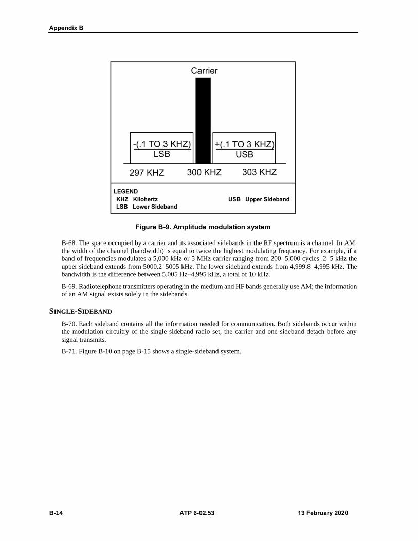
Appendix B
B-14 ATP 6-02.53 13 February 2020
Figure B-9. Amplitude modulation system
B-68. The space occupied by a carrier and its associated sidebands in the RF spectrum is a channel. In AM,
the width of the channel (bandwidth) is equal to twice the highest modulating frequency. For example, if a
band of frequencies modulates a 5,000 kHz or 5 MHz carrier ranging from 200–5,000 cycles .2–5 kHz the
upper sideband extends from 5000.2–5005 kHz. The lower sideband extends from 4,999.8–4,995 kHz. The
bandwidth is the difference between 5,005 Hz–4,995 kHz, a total of 10 kHz.
B-69. Radiotelephone transmitters operating in the medium and HF bands generally use AM; the information
of an AM signal exists solely in the sidebands.
SINGLE-SIDEBAND
B-70. Each sideband contains all the information needed for communication. Both sidebands occur within
the modulation circuitry of the single-sideband radio set, the carrier and one sideband detach before any
signal transmits.
B-71. Figure B-10 on page B-15 shows a single-sideband system.

Single-Channel Radio Communications Techniques
13 February 2020 ATP 6-02.53 B-15
Figure B-10. Single-sideband system
B-72. The upper side band is higher in frequency than the carrier is, and the lower sideband is lower in
frequency. Use either an upper or a lower sideband for communication, provided appropriate adjustment to
the transmitter and the receiver to the same sideband. Most Army single-sideband equipment operates in the
upper sideband mode.
B-73. The transmission of only one side band leaves open that portion of the RF spectrum normally occupied
by the other sideband of an AM signal. This allows more RF carriers within a given frequency range.
B-74. Single-sideband transmission is used in applications to—
Obtain greater reliability.
Limit size and weight of equipment.
Increase effective output without increasing antenna voltage.
Operate a large number of radio sets without heterodyne interference (whistles and squeals) from
RF carriers.
Operate over long ranges without loss of intelligibility due to selective fading.

This page intentionally left blank.

13 February 2020 ATP 6-02.53 C-1
Appendix C
Antenna Selection
Antenna type and antenna placement are critical to ensure optimum communications.
The appendix addresses the importance of high frequency, VHF, and UHF antenna
selection.
HIGH FREQUENCY ANTENNA SELECTION
C-1. Radio waves in the 3–30 MHz frequency range can reflect and return to Earth by the ionosphere with
predictable regularity. To optimize the probability of a successful skywave communications link, select the
frequency, and take-off angle most appropriate for the time of day transmission is to take place.
C-2. Various large conducting objects, the Earth’s surface, modify an antenna’s radiation pattern.
Sometimes nearby scattering objects may modify the antenna’s pattern favorable by concentrating more
power toward the receiving antenna.
C-3. When selecting an antenna site, the operator should avoid as many scattering objects as possible. The
near-vertical incidence skywave is the chief mode of short-haul HF propagation. Ground wave and directional
line of sight propagation are also useful over short paths. How far a ground wave is useful depends on the
electrical conductivity of the terrain or body of water over which it travels. The direct wave is useful only to
the radio horizon, which extends slightly beyond the visual horizon.
ANTENNA SELECTION PROCEDURES
C-4. Selecting the right antenna for an HF radio circuit is very important. When selecting an HF antenna,
first consider the type of propagation. Ground wave propagation requires low take-off angle and vertically
polarized antennas. The whip antenna included with most radio sets provides good omnidirectional ground
wave radiation.
C-5. Selecting an antenna for skywave propagation is very complex. First, find the circuit range distance to
ensure that the required take-off angle can be determined. A circuit distance of 966 kilometers 600 miles
requires a take-off angle of approximately 25 degrees during the day and 40 degrees at night. Select a high
gain antenna 25–40 degrees. If propagation predictions are available, skip this step, since the predictions give
the take-off angles required.
C-6. Next, determine the required coverage. A radio circuit with mobile vehicle stations or several stations
at different directions from the transmitter requires an omnidirectional antenna. A point-to-point circuit uses
either a bidirectional or directional antenna. Normally, the receiving station location dictates this choice. See
table C-1 on page C-2 for take-off angles versus distance.

Appendix C
C-2 ATP 6-02.53 13 February 2020
Table C-1. Take-off angle versus distance
Take off Angle
(Degrees)
Distance
F2 Region Daytime F2 Region Nighttime
kilometers miles kilometers miles
0 3220 2000 4508 2800
5 2415 1500 3703 2300
10 1932 1200 2898 1800
15 1450 900 2254 1400
20 1127 700 1771 1100
25 966 600 1610 1000
30 725 450 1328 825
35 644 400 1127 700
40 564 350 966 600
45 443 275 805 500
50 403 250 685 425
60 258 160 443 275
70 153 95 290 180
80 80 50 145 90
90 0 0 0 0
C-7. Before selecting an antenna, examine the available construction materials. Horizontal dipoles require
at least two supports to erect. A third (center) support is necessary for frequencies 5 MHz or lower. Operators
should not construct a dipole without the necessary support items. If the support items are unavailable, the
operator should select another antenna type. Planners and operators examine the proposed antenna site to
determine whether the antenna can fulfill the mission requirements. If not, the operator should select a
different antenna type.
C-8. Site selection is another important consideration. Usually, the tactical situation determines the position
of the communications antenna. The ideal setting would be clear, flat areas with no trees, fences, power lines,
or mountains. Unfortunately, the ideal location is seldom available. Choose the clearest, flattest area possible.
Situations often require constructing an antenna on an irregular site. This does not mean that the antenna will
not work. It means that the site affects the antenna’s pattern and function.
C-9. After selecting the antenna, determine how to feed the power from the radio to the antenna. The coaxial
cable (RG-213) feed most tactical antennas. Coaxial cable is a reasonable compromise of efficiency,
convenience, and durability. Issued antennas include the necessary connectors for coaxial cable or for direct
connection to the radio.
C-10. A balanced to unbalanced transformer prevents unwanted RF current flow, which causes a radio to be
hot to the touch or to shock the radio operator. Install the balanced to the unbalanced transformer at the dipole
feed point center to prevent unwanted RF current flow on the coaxial cable. If a balanced to unbalance
transformer is unavailable, use the coaxial cable that feeds the choke ring antenna Connect the cable’s center
wire to one leg of the dipole and the cable braid to the other leg. Form the coaxial cable into a 6-inch coil
consisting of ten turns, and tape it to the antenna under the insulator for support.
DETERMINING ANTENNA GAIN
C-11. Figure C-1 on page C-3 shows the vertical antenna pattern for the 32-foot vertical whip antenna. The
numbers along the outer ring 90, 80, and 70 degrees represent the angle above the Earth; 90 degrees would
be straight up, and 0 degrees would be along the ground. Along the bottom of the pattern are numbers from
-10 (at the center) to = 15 at the edges. These numbers represent decibels over an isotropic radiator.

Antenna Selection
13 February 2020 ATP 6-02.53 C-3
Figure C-1. 32-foot vertical whip, vertical antenna pattern
C-12. To find the antenna gain at a particular frequency and take-off angle, locate the desired take-off angle
on the plot. Follow that line toward the center of the plot to the pattern of the desired frequency. Drop down
and read the gain from the bottom scale. If the gain of a 32-foot vertical whip at 9 MHz and 20-degree take-
off angle desired, locate 20-degrees along the outer scale. Follow this line to the 9 MHz pattern line. Move
down to the bottom scale. The gain is a little less than 2.5 dBi. The gain of the 32-foot vertical whip at 9 MHz
and 20 degrees is 2 dBi.
C-13. Once the antenna’s overall characteristics are determined, use the HF antenna selection matrix (see
table C-2 on page C-4) to find the right antenna for a circuit. If the proposed circuit requires a short-range,
omnidirectional, wideband antenna, the selection matrix shows the only antenna that meets all the criteria is
the AS-2259/GR.

Appendix C
C-4 ATP 6-02.53 13 February 2020
Table C-2. HF antenna selection matrix
Use Directivity Polarization
Bandwidth
Gro
un
d W
ave
Skywave
Om
nid
irectio
na
l
Bid
irectio
na
l
Dire
ctio
nal
Ho
rizon
tal
Ve
rtica
l
Wid
e
Na
rrow
Sh
ort 5
00
Mile
s
Me
diu
m 5
00
to 1
20
0 M
iles
Lo
ng
12
00 M
iles
AS-2259/GR X X X
Vertical Whip X X X X
Half-Wave Dipole X X X X X
Long Wire X X X X X X X
Inverted L X X X X X X X X
Sloping V X X X X X X
Vertical Half Rhombic X X X X X X
UHF AND VHF ANTENNA SELECTION
C-14. The VHF portion of the radio spectrum extends from 30–300 MHz and the UHF range reaches from
300–3,000 MHz (3 GHz). Both frequency ranges are extremely useful for short-range less than 50 kilometers
or 31 miles communications. This includes point-to-point, mobile, air-to-ground, and general-purpose
communications. Wavelengths at these frequencies ranges are considerably shorter.
C-15. Because VHF and UHF antennas are small, it is possible to use multiple radiating elements to form
arrays, which provide a considerable gain in a direction or directions. An array is an arrangement of antenna
elements, usually, dipoles used to control the direction in which most of the antenna power radiates.
C-16. In the VHF and UHF portion of the spectrum, there are sub frequency bands for specific uses, such as
VHF aircraft band, UHF aircraft band, and public communications.
POLARIZATION
C-17. In many countries, FM and television broadcast in the VHF range using horizontal polarization. One
reason is that it reduces ignition interference, which is mainly vertically polarized. Mobile communications
often use vertical polarization or two reasons. First, the vehicle antenna installation has physical limitations,
and second, there is no interruption in the reception or transmission as the vehicle changes heading.
C-18. Using directional antennas and horizontal polarization when possible reduces manmade noise
interference in urban locations. Choose horizontal polarization only where an antenna height of many
wavelengths is possible. Ground reflections tend to cancel horizontally polarized waves at low angles. Use
only vertically polarized antennas when the antenna is less than 10 meters (32.8 feet) above the ground, or
when desiring omnidirectional radiation or reception.
GAIN AND DIRECTIVITY
C-19. VHF and UHF above 30 MHz antenna gain are extremely important for several reasons. Assuming the
same antenna gain and propagation path, the received signal strength drops as the frequency is increased. At
VHF and UHF, more of the received signal is lost in the transmission line than is lost at HF. A 10–20 dB loss
is uncommon in a 30-meter (98.4 feet) length of the coaxial line at 450 MHz.

Antenna Selection
13 February 2020 ATP 6-02.53 C-5
C-20. At frequencies below 30 MHz, system sensitivity is usually limited by receive noise rather than by
noise external to the antenna. Generally, wider modulation or signal bandwidths employ in VHF and UHF
transmissions than at HF. Since system noise power is directly proportional to bandwidth, additional antenna
gain is necessary to preserve a usable signal to noise ratio.
C-21. VHF and UHF antenna directivity gain aids security by restricting how much power radiated in
unwanted directions. Receiver sensitivity is generally poorer at VHF and UHF except for high quality state-
of-the-art receivers. Obstructions buildings, trees, hills may seriously decrease the signal strength available
to the receiving antenna because VHF and UHF signals travel a straight line of sight path.
C-22. Obtaining communications reliability over difficult VHF and UHF propagation paths requires
considerable attention to the design of high-gain directive antenna arrays. Unlike HF communications, the
shorter VHF and UHF wavelengths support walkie-talkie transceivers and simple mobile transmissions units.
Communicating or receiving with such devices over distances beyond 1 or 2 kilometers requires maximum
antenna gain at the base station or fixed end of the link.
C-23. An array provides directivity the ability to concentrate radiated energy into a beam directed toward the
intended receiver. Arrays of resonant elements, half-wave dipoles, constructed of rigid metal rods or tubing
or copper foil laid out or pasted on a flat non-conducting surface. Directing power helps to increase the range
of the communications path and tends to decrease the likelihood of the interception of jamming from hostile
radio stations. Highly directive antennas place an added burden on the radio operator to ensure that the
antenna is properly oriented.
ANTENNA PLANNING PROGRAMS
C-24. Several line of sight radios require the planner or operator to do an analysis and prediction of the
antennas line of sight paths to ensure the availability of communications from different planned locations.
There are programs designed to generate, store, and disseminate communications information for antenna
analysis and prediction.
SYSTEM PLANNING, ENGINEERING AND EVALUATION DEVICE
C-25. The Marine Corps Tactical Systems Support Activity hosts the system planning, engineering, and
evaluation device program. The system planning, engineering, and evaluation device is a software package
that provides communications planners with the tools necessary to engineer and plan radio communications
analysis.
C-26. The system planning, engineering, and evaluation device is a complete stand alone, self-installing
software package that provides the tools necessary to plan and analyze communications equipment. The
software contains HF analysis, radio coverage analysis, point-to-point, and satellite planning tools, which
allows planning in response to rapidly changing communications architectures.
C-27. Communications planners load topographical information before each operation to generate reports,
maps, and matrices.
VOICE OF AMERICA COVERAGE ANALYSIS PROGRAM
C-28. Voice of America Coverage Analysis Program software released to the public is downloadable from
the U.S. Department of Commerce National Telecommunications Information Administration, Institute for
Telecommunications Sciences; Boulder, Colorado to use as an HF prediction and analysis tool. Voice of
America is a component of the International Bureau of Broadcasting, which is a member of the Broadcasting
Board of Governors.
Voice of America Coverage Analysis Program offers the following capabilities—
Easy to use graphical user interface.
Detailed point-to-point graphs.
Signal–to-noise radio.
Required power gain.
Signal power.

Appendix C
C-6 ATP 6-02.53 13 February 2020
Maximum usable frequency.
Take-off and arrival angle.
Point-to-point performance versus distance for any given parameters at one or all user assigned
frequencies.
Calculates methods for antenna patterns.
C-29. Planners must input several parameters before the Voice of America Coverage Analysis Program can
provide a propagation prediction determined by the method and the antennas used.
IONOSPHERIC COMMUNICATIONS ENHANCED PROFILE ANALYSIS AND CIRCUIT
PREDICTION PROGRAM
C-30. The ionospheric communications enhanced profile analysis and circuit prediction program is a full
system performance model for HF radio communications in the frequency range of 2–30 MHz. capable of
daily prediction methods with improved high latitude propagation models. The ionospheric communications
enhanced profile and circuit prediction program provides ionospheric communications analysis and
prediction with an ionospheric conductivity and electron density profile model added, which is a statistical
model of the large-scale features of the northern hemisphere ionosphere.

13 February 2020 ATP 6-02.53 D-1
Appendix D
Communications in Austere Environments
The appendix addresses radio operations in cold weather, jungle, urban, desert,
mountain areas, and nuclear areas. Communications in austere unusual environments
require special consideration.
COLD WEATHER OPERATIONS
D-1. Single-channel radio equipment has certain capabilities and limitations that require careful
consideration when operating in extremely cold weather. Despite significant limitations, the radio is still the
normal means of communication in such environments.
D-2. One of the most important attributes of a radio in cold weather operations is versatility. Vehicle-
mounted radios can move to almost any location where there is a command headquarters. Smaller, man
packed radios move to any area accessible by aircraft or on foot.
D-3. Electromagnetic interference by ionospheric disturbances limits radio communications in extremely
cold areas. These disturbances, known as ionospheric storms, have a definite degrading effect on skywave
propagation. Ionospheric storms and the Northern Lights activity can cause complete failure of radio
communications. Static may block out some frequencies completely for extended periods during storm
activity. Fading, caused by changes in the density and height of the ionosphere can also occur and may last
for several minutes to several weeks. These occurrences are difficult to predict, but when they do occur, the
frequency manager will assign alternate frequencies.
TECHNIQUES FOR BETTER COMMUNICATIONS IN COLD WEATHER
D-4. When possible, install radio sets for tactical operations in vehicles to reduce the problem of
transportation and shelter for radio operators. This resolves some of the grounding and antenna installation
problems due to the climate.
D-5. It is difficult to establish good electrical grounds in extremely cold areas because of permafrost and
deep snow. The conductivity of frozen ground is often too low to provide good ground wave propagation.
To improve ground wave operation, use a counterpoise to offset the degrading effects of poor electrical
ground conductivity. Install a counterpoise to prevent snow from covering an antenna. If possible, install the
antenna high enough above the ground to prevent snow from covering the antenna.
D-6. In general, antenna installation in arctic-like areas presents no serious difficulties. Installation of
antennas may take longer due to adverse working conditions. Tips for installing antennas in extremely cold
areas include—
Handle the mast sections and antenna cables carefully since they become brittle in very low
temperatures.
Construct antennas overhead to prevent damage from heavy snow and frost.
Use nylon rope if available, in preference to cotton or hemp, because nylon ropes do not readily
absorb moisture, and are less likely to freeze and break.
Use extra wires, supports, and anchor stakes to strengthen antennas and to withstand heavy ice
and wind loading.
D-7. Some radios, generally older generation radios adjusted to a frequency in a relatively warm place, may
drift off frequency when exposed to extreme cold. Low battery voltage can also cause frequency drift. When
possible, allow a radio to warm up several minutes before placing it into operation. Since extreme cold tends

Appendix D
D-2 ATP 6-02.53 13 February 2020
to lower the output voltage of a dry battery, try warming the battery with body heat before operating the radio
set, this minimizes frequency drift.
D-8. Northern regions sometimes experience flakes or pellets of highly electrically charged snow. When
these particles strike the antenna, the resulting electrical discharge causes a high-pitched static roar that can
blanket all frequencies. To overcome this static, cover antenna elements with polystyrene tape and shellac.
MAINTENANCE IMPROVEMENT IN COLD WEATHER
D-9. The maintenance of radio equipment in extreme cold presents many difficulties. Protect radio sets from
blowing snow because snow freezes dials, knobs, and can get into the wiring, which causes shorts and ground.
Carefully handle cords and cables as they may lose their flexibility in extreme cold. Winterize all radio
equipment and power units. Check the appropriate TM for winterization procedures. The following
paragraphs provide suggestions for radio maintenance in arctic areas.
Power Units
D-10. As the temperature goes down, it becomes increasingly difficult to operate and maintain generators.
Protect generators as much as possible from the weather.
Batteries
D-11. The effect of cold weather conditions on wet or dry cell batteries depends on the type of battery, the
load on the battery, and the degree of exposure to cold temperatures. Batteries perform best at moderate
temperatures and generally have a shorter life at very cold temperatures.
Shock Damage
D-12. Damage may occur to vehicular radio sets by the jolting of the vehicle. Most synthetic rubber shock
mounts become stiff and brittle in extreme cold and fail to cushion equipment. Check the shock mounts
frequently and change them as required.
Winterization
D-13. Check the TMs for the radio set and power source to see if there are special precautions for operation
in extremely cold climates. For example, normal lubricants may solidify and permit damage or malfunctions
to the radio equipment. Replace normal lubricants with the recommended arctic lubricants. A light coat of
silicon compound on antenna mast connections helps to keep them from freezing together and becoming hard
to dismantle.
Microphones
D-14. Use standard microphone covers to prevent moisture from breath freezing on the perforated cover plate
of the microphone. If standard covers are not available, improvise a suitable cover from rubber or cellophane
membranes, or from rayon or nylon cloths.
Breathing and Sweating
D-15. A radio set generates heat when operated. The air inside a powered off radio set cools and contracts,
drawing cold air into the set from the outside. This is breathing. When a radio breathes, and the still-hot parts
encounter subzero air, the glass, plastic, and ceramic parts of the set may cool too rapidly and break.
D-16. Sweating occurs when cold equipment suddenly encounters warm air and moisture condenses on the
equipment parts. Before locating cold equipment into a heated area, wrap the equipment in a blanket or parka
to ensure that it warms gradually to reduce sweating. Equipment must be thoroughly dry before taking it back
into the cold air, or the moisture freeze.

Communications in Austere Environments
13 February 2020 ATP 6-02.53 D-3
Vehicular Mounted Radios
D-17. Vehicle mounted radios present obvious challenges during winter operations caused by exposure to
the elements. Observe proper starting procedures. The radio’s power switch must be off before starting the
vehicle, especially when vehicles are slave-started. If the radio is cold soaked from a prolonged shutdown,
frost may have collected inside the radio and could cause circuit arcing. Allow time for the vehicle’s heater
to warm the radio sufficiently to ensure that any frost collected on or inside the radio has a chance to thaw.
D-18. The defrosting process may take up to an hour. After turning the radio on, allow it to warm up for
approximately 15 minutes before transmitting or changing frequencies. This allows components to stabilize.
D-19. A vehicle operated at a low idle with radios, heater, and lights on may drain the batteries. Before
increasing engine revolutions per minute, charge the batteries. Turn off radios to avoid an excessive power
surge.
OPERATIONS IN JUNGLE AREAS
D-20. Limitations on radio communications in jungle areas stem from the climate and the density of jungle
growth. The hot and humid climate increases the maintenance problems of keeping equipment operable.
Thick jungle growth acts as a vertically polarized absorbing screen for RF energy that, in effect, reduces the
transmission range. Therefore, increased emphasis on maintenance and antenna site selection is inherently
important when operating in jungle areas.
D-21. Radio communications in jungle areas require careful planning. Dense jungle growth, heavy rains, and
hilly terrain all significantly reduce the range of radio transmission. Trees and underbrush absorb VHF and
UHF radio energy. In addition to the ordinary free space loss between transmitting and receiving antennas, a
radio wave passing through a forest undergoes an additional loss. This extra loss increases rapidly as the
transmission frequency increase. Near the ground (antenna heights of less than 3 meters [9.8 feet]) vertical
polarization is preferred. If possible elevate the receiving and transmitting antenna as much as 10–20 meters
(32.8–65.6 feet), horizontal polarization is preferable to vertical polarization. Considerable reduction in total
path loss results if either the transmitting or receiving antenna placement occurs above tree level through
which wave propagation occurs.
D-22. Single-channel radios deploy in many configurations, especially man packed, which make it a valuable
communications asset. Carefully consider the capabilities and limitations of tactical radios when used by
friendly forces in a jungle environment. The mobility and various configurations in which the tactical radio
deploy are its primary advantages in jungle areas.
TECHNIQUES FOR BETTER COMMUNICATIONS IN JUNGLE AREAS
D-23. The site selection of the antenna is the main problem in establishing radio communications in jungle
areas. Techniques to improve communications in the jungle include—
Place antennas in clearings on the edge farthest from the distant station, and as high as possible.
Keep antenna cables and connectors off the ground to lessen the effects of moisture, fungus, and
insects. This also applies to all power and telephone cables.
Use complete antenna systems, as broadband and dipoles. They are more effective than fractional
wavelength whip antennas.
Clear vegetation from antenna sites. If an antenna touches any foliage, especially wet foliage,
grounding of the signal occurs.
Use horizontally polarized antennas in preference to vertically polarized antennas because
vegetation, particularly when wet, act as a vertically polarized screen and absorb much of any
vertically polarized signal.
MAINTENANCE IMPROVEMENT IN TROPICAL AREAS
D-24. Maintenance of radio sets in tropical climates is more difficult than in temperate climates due to
excessive amounts of moisture and fungus. The high relative humidity causes condensation to form on the
equipment and encourages the growth of fungus. Radio operators and maintenance personnel should check

Appendix D
D-4 ATP 6-02.53 13 February 2020
the appropriate TMs for any special maintenance requirements. Techniques for improving maintenance in
jungle areas include—
Keep the equipment as dry as possible and in lighted areas to retard fungal growth.
Keep air vents clear of obstructions to ensure that air can properly circulate for cooling and drying
of the equipment.
Use moisture and fungus proofing paint, tape, or silicone grease to protect equipment after repairs,
or to protect damaged or scratched painted surfaces.
EXPEDIENT ANTENNAS
D-25. Dismounted patrols and units of company-size and smaller can improve their ability to communicate
in the jungle by using expedient antennas. While moving, users are generally restricted to the short or long
whip antennas that come with their manpack radios. Using an expedient antenna when stationary allows users
to broadcast farther and receive more clearly. Circuits inside the radio load the whips properly to tune the
radios to give maximum output. Whips antennas are not as effective as a tuned doublet or as broadband as
the OE-254 tuned to the operating frequency.
D-26. When used properly, the expedient OE-254 type antenna increases the ability to communicate. The
OE-254 antenna system is bulky and heavy. Therefore, it is not generally acceptable for dismounted patrols
or small-unit operations. A Soldier can manage by, carrying only the masthead and antenna sections,
mounting these on wooden poles, or hanging them up when not on the move.
OPERATIONS IN URBAN AREAS
D-27. Radio communications in urbanized terrain pose special problems. When the Army engages in urban
combat operations the communications situation is considerably different from the situation faced by civil
government or cell phone users. Military factors include—
Restriction of operation to the frequency range of common military radios (2–512 MHz).
Limits on the output power of military radio equipment.
Limited number of available repeater assets if any.
Limited access to good repeater locations due to enemy action.
Need to communicate to both outside street locations and inside structures.
Lack of standard compact antenna systems useful for urban combat.
Severe restrictions on the movements of system users.
Lack of man-power required to cover multiple signal sites can easily exceed available resources.
Problems with man-made obstacles or line of sight obstructions blocking transmission paths.
Problems with poor electrical conductivity due to pavement surfaces.
Problem with commercial power lines interference.
Distorted radio wave propagation in built-up areas and the limited availability of open lines of
communication make it difficult to move and install fixed station and multichannel systems.
D-28. FM and VHF radios have their effectiveness reduced in built-up areas. The operating frequencies and
power output of these sets demand line of sight between antennas. Line of sight at street level is not always
possible in built-up areas. AM HF sets are less affected by the line of sight problem because operating
frequencies are lower, yet power output is greater. In experiences, HF radios were not organic to the small
units that conducted clearing operations. RETRANS of VHF signals overcomes this limitation if available to
use.
TECHNIQUES FOR BETTER COMMUNICATIONS IN URBAN AREAS
D-29. When available, RETRANS stations in aerial platforms could provide the most effective means;
depending on the requirement, use organic RETRANS sets. Hide or blend radio antennas in with the
surroundings to ensure they will not be landmarks for the enemy to locate. Water towers, commercial
antennas, and steeples can conceal military antennas.

Communications in Austere Environments
13 February 2020 ATP 6-02.53 D-5
D-30. Lay wire while friendly forces are in static positions, but careful planning is necessary. Use existing
telephone poles to raise wire lines above the streets. Use ditches, culverts, and tunnels to keep the wire below
the streets. If not taken as precautions, tracked and wheeled vehicles constantly tear lines apart, and disrupt
communications.
D-31. Messengers provide security and flexibility. Carefully select messenger routes to avoid pockets of
enemy resistance. Vary routes and time schedules to avoid establishing a pattern. Pyrotechnics, smoke, and
marker panels are also excellent means for communicating, but they require coordination and understanding
by air and ground forces. The noise of combat in built-up areas makes it difficult to use sound signals
effectively.
D-32. The possible seizure or retention of established communications facilities must be included in planning.
Make every effort to prevent damage or destruction of these facilities. The local telephone system is already
in place and tailored to the city or town. Army forces use local telephone systems to provide immediate
access to wire communications with overhead and buried cable. This procedure helps overcome the problems
encountered with radios and provides a cable system less susceptible to combat damage.
D-33. Local media, as the newspapers, radio stations, and television stations, provide communications with
the local populace after the level of combat declines. Intact police or taxi communications facilities are also
possible radio systems, tailored to the city, with RETRANS facilities already in place.
D-34. Radio equipped vehicles should be parked inside of buildings for cover and concealment when
possible; dismount radio equipment, and install it inside buildings in basements, if available. Place generators
against buildings or under sheds to increase noise absorption, provide concealment, and always remember to
ensure adequate ventilation is available.
D-35. Another important consideration for urban combat is raw power. The more power used, the more path
loss and the deeper the signals penetrate structures. Common tactical VHF man-pack radios like SINCGARS
have a maximum output power of four watts. The AN/PRC-150 I HF radio has a maximum output power of
20 watts. That is 7 dB more signal power to overcome losses caused by the path, path obstructions, inefficient
antennas, and other signal consuming factors. The extra power improves the radio capabilities. The following
are examples of power relationships—
4 watts = 36 decibels above one milliwatt (dBm).
20 watts = 43 dBm.
50 watts = 47 dBm.
150 watts = 52 dBm.
400 watts = 56 dBm.
D-36. The dB is a logarithmic unit used to describe a ratio. The ratio may be power, voltage, intensity, or
several other factors but in this case, its power watts. If radio operators look at the math, they can measure
the difference of two power levels by taking a logarithm of log 10 of their power ratio. If the ratio of power
is, for example, two, meaning one radio transmitter is double the power of the other, the difference is 3dB.
Every 3dB gained through a more efficient antenna system or reduced transmission line loss is the equivalent
of doubled transmitter power.
D-37. The important point is that often, adjustments to antenna systems or operational frequencies to make
an antenna more efficient can produce far more dBs of signal power than simply increasing the raw
transmitter power. More power assists in overcoming path loss for the near-vertical incidence skywave and
ground wave systems but many times the best or only answer to the problem. If the radio is already
transmitting at maximum power, then these adjustments (to the antenna systems or frequencies) are the only
way to compensate for path loss and improve signal penetration in the urban combat environment.
Note. It is important to remember that in many situations the power required to operate a radio
may not need to be at the maximum power, use only the power necessary to operate.
D-38. Communications between two radio stations requires that the transmitter power-transmitter antenna
gain-receiver antenna gain-receiver performance overcome the path loss between stations. A base station
typically uses a higher performance receiver and a more efficient antenna, and can compensate for a low

Appendix D
D-6 ATP 6-02.53 13 February 2020
power outstation radio, like the manpack radio used by forward troops with its inefficient antenna. When
reserving the path, typically higher-power base-station transmitter and the more efficient antenna again
compensates for lower performing combat unit radios in the net. Communications between low-power
outstations are much more difficult and may even require RETRANS through a more efficient base station.
D-39. In urban operations, small HF radios, like the AN/PRC-150 I, are extremely portable, but are antenna
and power challenged based on location. To obtain a high degree of portable near-vertical incidence skywave
effect when needed by physically reorienting standard vertical man-pack or vehicle (whip) antennas to the
horizontal plane. Direct (surface wave) signals are simpler to generate and use inside structures produced
from the same antenna by just leaving the antenna vertical.
D-40. Because of their longer wavelengths, lower frequency HF 2–30 MHz signals naturally penetrate urban
structures deeper than signals on higher, shorter wavelength frequencies. How deep the penetration depends
on exact frequency, signal power level, antenna efficiency and the makeup of the urban structures in the path.
D-41. In radio communications and particularly urban combat radio communications, is important to
overcome path loss. The greater the radiated signal, the lower the frequency, the more path loss reduction.
This raises the probability of successful communications in urban areas and inside buildings.
D-42. As an example of HF signal penetration, is not uncommon for a small ground penetrating radar
transmitter operating in the HF frequency range to penetrate over 100 feet 30.4 meters into common kinds of
earth while the same power radar on a higher frequency penetrate much less. If the radio operator is using a
common VHF military radio operating at 30 MHz (lowest frequency for single-channel ground-to-air radio
systems) and replaces it with an HF radio AN/PRC-150 I, operating at 5 MHz the path loss drops by 20 dB
because of the way that longer wavelength lower frequency signals propagate. In this case, lowering the
frequency is the equivalent to increasing the power of the transmitter by a factor of almost seven.
OPERATIONS IN DESERT AREAS
D-43. Radios are usually the primary means of communications in the desert. Radios employed in desert
climate and terrain provide the highly mobile means of communications required for widely dispersed forces.
Desert terrain provides poor electrical ground and counterpoises are needed to improve operation. The
following paragraphs address operations in desert or arid areas.
D-44. Dust and extreme heat are two of the biggest problems involved in desert operations. Temperatures
may vary from 58º Celsius 136º Fahrenheit in summer to -46º Celsius -50º Fahrenheit in winter. The heat can
take a toll on generators, wire, communications equipment, and personnel.
D-45. Dust and sand particles damage equipment. Some combat net radios have ventilating ports and
channels that may clog with dust. Operators should check and clean these ports regularly to prevent
overheating.
D-46. In a desert environment, operators should ground equipment by burying ground plates in the sand and
pouring salt solutions on the ground plates. Daily equipment maintenance checks should include cleaning
generators and air filters to prevent equipment damage.
TECHNIQUES FOR BETTER COMMUNICATIONS IN DESERT AREAS
D-47. Cut or adjust antennas to the length of the operating frequency. Emplace antennas in the required
direction. Approximate azimuth produced by guesswork is not sufficient. A whip antenna relies on the
capacitor effect, between itself and the ground, for efficient propagation. The electrical ground may be very
poor and degrade the antenna performance by as much as one-third if the surface soil lacks moisture, which
is normally the case in the desert.
D-48. If a ground-mounted antenna is not fitted with a counterpoise (see chapter 10 for more information on
a counterpoise), dampen the ground around it using any fluid available. Vehicle mounted antennas are more
efficient if the mass main structure of the vehicle is forward of the antennas and is oriented toward the distant
station.
D-49. Keep radios cool and clean in accordance with preventive maintenance procedures. Operate them in a
shaded or ventilated area, and at low power whenever possible. Place a flat sheet of wood, cardboard, or a

Communications in Austere Environments
13 February 2020 ATP 6-02.53 D-7
vehicle’s canvas top over the top of the radio to create man-made shade. Leaving a space between the wood,
cardboard, and the radio, help to cool the radio by causing air to circulate in the shaded area between the
radio and the wood. Carefully covering hot radios with a damp cloth without blocking ventilation outlets
allows moisture evaporation from the cloth to cool the radio.
DESERT TERRAIN
D-50. Desert terrain can cause excessive signal attenuation, making planning ranges shorter. Desert
operations require dispersion, yet the environment is likely to degrade the transmission range of radios,
particularly VHFs FM fitted with secure equipment. This degradation is most likely to occur during the
hottest part of the day, from approximately 1200–1700.
D-51. If, during the hottest time of day, radio stations begin to lose contact, alternative communications plans
must be ready, and may include—
Using RETRANS capabilities, including airborne RETRANS capabilities the aircraft must remain
at least 4,000 meters behind the line of contact. Plan RETRANS in conjunction with the scheme
of maneuver.
Deploying any unemployed vehicle with a radio as RETRANS between stations.
Using alternative radio links, like the VHF multichannel telephones a higher level or HF single-
sideband voice.
D-52. After dark, a rapid temperature drop creates heat inversion. This inversion can disrupt radio
communications until the atmosphere stabilizes.
D-53. Wired connections are impractical during high-tempo military operations. Wire may be of some value
in static defensive situations. When possible, installers and operators should bury wire and cables deep in the
soft sand to prevent heat damage to cable insulation and prevent vehicle or foot traffic damage.
D-54. Operators should protect computers and removable storage media from dust and sand. Covering
computers and disks with plastic bags may reduce damage. Covering computers and radios for an extended
period may cause condensation inside these components, resulting in equipment damage or data loss. Canned
compressed air is a useful tool to clean keyboards and other components.
D-55. Wind-blown sand and grit can damage electrical wire insulation over time. Tape can help protect cables
from sand damage. Sand may also work into parts of items such as spaghetti cord plugs, either preventing
electrical contact or making it impossible to join the plugs together. A soft brush, like an old toothbrush, can
clean cords and plugs before connection.
D-56. Static electricity is prevalent in the desert. Many factors cause static electricity. One factor is wind-
blown dust particles. Extremely low humidity contributes to static discharges between charged particles. Poor
grounding practices exacerbate the problem. Operators should tape all sharp edges and tips of antennas to
reduce wind-caused static discharges and the accompanying noise. When operating from a fixed position,
operators should install a proper earth ground (refer to TC 6-02.6). Since static-caused noise diminishes with
an increase in frequency, operators should use the highest frequency that is available and authorized.
OPERATIONS IN MOUNTAINOUS AREAS
D-57. Radio operations in mountainous areas share some of the same challenges as in cold weather areas.
Mobility is difficult in mountainous terrain, and it can be difficult to find a level area to establish a
communications site.
D-58. Generators and communications equipment need level ground for proper operation. It may difficult to
drive ground rods and guy wire stakes into rocky, ground, so an alternate grounding method may be
necessary. Rocky soil provides poor ground conductivity. Adding salt solutions improves electrical flow.
D-59. Operating in mountainous terrain may require additional RETRANS assets. Line of sight paths are
more difficult to establish in this terrain. Plans should include the use of RETRANS to improve
communications range. Positioning of antennas is crucial in mountainous terrain, as moving an antenna even
a short distance can drastically affect reception.

Appendix D
D-8 ATP 6-02.53 13 February 2020
OPERATIONS IN A NUCLEAR AREA
D-60. A nuclear area adversely affects sensitive radio equipment and components. Operators should take
measures to protect signal equipment and ensure equipment survivability and availability for future use.
Nearly everyone is aware of the heat, and radiation effects of a nuclear blast. The ionization of the atmosphere
by a nuclear explosion will degrade communications because of static and the disruption of the ionosphere.
D-61. Electromagnetic pulse is the radiation generated by a nuclear detonation. Gamma rays, high-energy
photons, radiate outward from the point of the nuclear detonation and strip electrons from the atoms in the
air. This creates a wall of fast-moving, negatively charged electrons, which undergo rapid deceleration,
radiating an intense electromagnetic field. This electromagnetic energy affects unprotected communications
equipment, causing disruption and destruction of delicate circuitry and components. The residual ionized
cloud also causes disruption of transmissions.
D-62. A high-altitude electromagnetic pulse can disable electronic systems as far as 6,000 kilometers (3,720
miles) from the site of the detonation. Electromagnetic pulse can also cause severe disruption and sometimes
damage when other weapon effects are absent. The enemy may use a high-yield nuclear weapon exploded
above the atmosphere to knock out single-channel TACSAT without causing any other significant damage.
The range of an electromagnetic pulse shortens if the weapon detonates at a lower altitude.
D-63. A typical high-altitude electromagnetic pulse could have an intensity one thousand times more intense
than a radar beam. A radar beam has enough power to cause biological damage to the human body like
blindness or sterilization. The electromagnetic pulse is broad spectrum and extends from low frequencies
into the UHF band. The most likely electromagnetic pulse effect would be temporary disruption of
communications. This can occur even without permanent damage. This delay could give an enemy enough
of an advantage to change the outcome of a battle.
D-64. TACSAT systems incorporate built-in features and techniques to counter electromagnetic pulse
effects. Shielding can further reduce the level of electromagnetic pulse. Shielding uses equipment location
and probable directions of nuclear blasts to reduce exposure. Shielding also depends on good earth ground.
Electronic equipment is very susceptible to electromagnetic pulse.
D-65. Equipment not required in primary systems should remain disconnected and stored in sealed shelters
or other shielded enclosures to protect against electromagnetic pulse. This reduces the likelihood of the
simultaneous damage to the equipment and provides a source of backup components to reinstall affected
systems.
D-66. Installers and operators should shield and properly ground wire and cable and keep cable length as
short as possible. Operators connect cable shields to the grounding systems, whenever possible. Effective
grounding is necessary to reduce electromagnetic pulse effects. Most tactical radios with fully enclosed metal
cases provide adequate protection, if external connectors are disconnected. Placing radios in vehicles, vans,
and underground shelters may enhance protection.
GENERAL RADIO SITE CONSIDERATIONS
D-67. The reliability of radio communications depends largely on the selection of a good radio site. Since it
is difficult to select a radio site that satisfies all technical, tactical, and security requirements, signal planners
should select the most suitable site available. Sites selection considers defensibility and logistical
supportability as well as communications suitability. Refer to FM 6-02 for more information on site selection.
D-68. Site selection is a leader and operator responsibility. It is also good planning to select a primary site
and an alternate site. If, for some reason, radio communications cannot be established and maintained at the
primary location, operations should move to the alternate site.
D-69. Planners and operators should locate radio stations in a position that ensures communications with the
other stations while maintaining site security and defense. To obtain efficiency of transmission and reception,
the following factors should be considered—

Communications in Austere Environments
13 February 2020 ATP 6-02.53 D-9
For operation at frequencies above 30 MHz planners should select a location that allows line of
sight communications.
Planners should avoid locations that provide the enemy with a jamming capability, visual sighting,
or easy interception.
Dry ground has high resistance and limits radio range. If possible, planners should locate the
station near moist ground, which has much less resistance. Water, especially fresh water, greatly
increases the distances covered.
Operators should install antennas away from foliage and dense brush.
Trees and shrubs can provide cover, concealment, and screening from enemy jamming.
When located near man-made obstructions—
Site selection should avoid tunnels, underpasses, and steel bridges due to the high absorption
of RF energy.
Radio sites should avoid buildings between radio stations, particularly steel and reinforced
concrete structures since they interfere with transmission and reception.
Buildings can effectively camouflage antennas from enemy observation.
Radio sites should avoid suspended telephone, telegraph, and high-tension power lines. Wire
lines absorb RF energy from radiating antennas in their vicinity. They also introduce
humming and noise interference in receiving antennas.
Radio sites should avoid heavily traveled roads and highways. In addition to the noise and
confusion caused by tanks and trucks, vehicle ignition systems may cause electrical
interference.
Operators should locate battery charging units and generators away from radio stations.
Operators should not locate radio stations close to one other.
Planners should select radio sites in relatively quiet areas to avoid distraction by outside
noises. The copying of low-level received messages requires great concentration by the radio
operator.
LOCAL COMMAND REQUIREMENTS
D-70. Radio stations should be located some distance from the unit headquarters or command post they serve.
This distance separation ensures that enemy direction-finding capability will not target the command post
with long-range artillery fire, missiles, or aerial bombardment.
D-71. The locations selected should provide the best cover and concealment possible, consistent with good
transmission and reception. Perfect cover and concealment may impair communications. The permissible
amount of impairment depends upon the range required, the power of the transmitter, the sensitivity of the
receiver, the efficiency of the antenna system, and the nature of the terrain. When a radio communicates over
a distance that is well under the maximum range, some sacrifice of communications efficiency takes place to
permit better concealment of the radio from enemy observation.
PRACTICAL CONSIDERATIONS
D-72. Manpack radio sets have sufficiently long cordage to permit operation from a concealed position (set
and operator), while the antenna is mounted in the best position for communications. Some radio sets are
remotely controllable from distances of greater than 30 meters. The remotely controlled set can be established
in a relatively exposed position, while the radio operator remains concealed.
D-73. Operators should install radio antennas above ground level to permit normal communications. Small
tactical radios usually use whip antennas. These antennas are difficult to see from a distance, especially when
not silhouetted against the sky. Because they have a 360-degree radiation pattern, they are extremely
susceptible to enemy interception and direction finding.
D-74. Antenna site selection should avoid open crests of hills and mountains. A position protected from
enemy fire just behind the crest gives better concealment and sometimes provides better communications.

Appendix D
D-10 ATP 6-02.53 13 February 2020
Operators should camouflage permanent and semi-permanent positions for protection from aerial and ground
observation. The antenna should not touch trees, brush, or the camouflage material.
D-75. One well-positioned broadband antenna and a FHMUX can serve several radios. This allows quicker
setup and teardown, and reduces time and materials required to camouflage the site.
RADIO OPERATOR SKILLS
D-76. The radio operator’s skills and technical abilities play important roles in maximizing communications
range. Correctly tuning the transmitter, output coupling, and antenna feeder circuits helps achieve maximum
power output. Operators should properly construct the radiating and receiving antennas, considering antenna
electrical characteristics and local terrain conditions. The radio operator provided the primary defense against
enemy electromagnetic interference. The radio operator’s skills can be the determining factor in maintaining
communications despite an enemy’s efforts to disrupt it.

13 February 2020 ATP 6-02.53 E-1
Appendix E
Julian Date, Synchronization Time, and Time Conversion
Accurate time is essential for single-channel ground airborne radios to operate in the
frequency-hopping mode. This appendix addresses the Julian date, synchronization
time, and ZULU time. A time variance greater than plus or minus four seconds can
disrupt the single-channel ground airborne radios frequency-hopping communications.
JULIAN DATE
E-1. The SINCGARS uses a special two-digit form of the Julian date as part of the synchronization time.
The two-digit Julian date begins with 01 on 1 January and continues through 00, repeating as necessary to
cover the entire year.
E-2. Table E-1 on page E-2 shows the two-digit Julian date calendar for a regular year. The two-digit Julian
year terminates on 65 (or 66 for the leap year), every 1 January change the Julian date to 01. This can be
accomplished by—
The NCS sending an electronic remote refill.
Operators reloading time directly from a DAGR.
Operators manually changing the date in the radio by using the RT keypad.

Appendix E
E-2 ATP 6-02.53 13 February 2020
Table E-1. Two-digit Julian date calendar (regular year)
Day JAN FEB MAR APR MAY JUN JUL AUG SEP OCT NOV DEC
1 01 32 60 91 21 52 82 13 44 74 05 35
2 02 33 61 92 22 53 83 14 45 75 06 36
3 03 34 62 93 23 54 84 15 46 76 07 37
4 04 35 63 94 24 55 85 16 47 77 08 38
5 05 36 64 95 25 56 86 17 48 78 09 39
6 06 37 65 96 26 57 87 18 49 79 10 40
7 07 38 66 97 27 58 88 19 50 80 11 41
8 08 39 67 98 28 59 89 20 51 81 12 42
9 09 40 68 99 29 60 90 21 52 82 13 43
10 10 41 69 00 30 61 91 22 53 83 14 44
11 11 42 70 01 31 62 92 23 54 84 15 45
12 12 43 71 02 32 63 93 24 55 85 16 46
13 13 44 72 03 33 64 94 25 56 86 17 47
14 14 45 73 04 34 65 95 26 57 87 18 48
15 15 46 74 05 35 66 96 27 58 88 19 49
16 Julian DateCalendar (Regular Year)
16 47 75 06 36 67 97 28 59 89 20 50
17 17 48 76 07 37 68 98 29 60 90 21 51
18 18 49 77 08 38 69 99 30 61 91 22 52
19 19 50 78 09 39 70 00 31 62 92 23 53
20 20 51 79 10 40 71 01 32 63 93 24 54
21 21 52 80 11 41 72 02 33 64 94 25 55
22 22 53 81 12 42 73 03 34 65 95 26 56
23 23 54 82 13 43 74 04 35 66 96 27 57
24 24 55 83 14 44 75 05 36 67 97 28 58
25 25 56 84 15 45 76 06 37 68 98 29 59
26 26 57 85 16 46 77 07 38 69 99 30 60
27 27 58 86 17 47 78 08 39 70 00 31 61
28 28 59 87 18 48 79 09 40 71 01 32 62
29 29 88 19 49 80 10 41 72 02 33 63
30 30 89 20 50 81 11 42 73 03 34 64
31 31 90 51 12 43 04 65
E-3. Table E-2 on page E-3 shows the two-digit Julian date calendar for a leap year.

Julian Date, Synchronization Time, and Time Conversion
13 February 2020 ATP 6-02.53 E-3
Table E-2. Two-digit Julian date calendar (leap year)
Julian Date Calendar (Leap Year)
Day JAN FEB MAR APR MAY JUN JUL AUG SEP OCT NOV DEC
1 01 32 61 92 22 53 83 14 45 75 06 36
2 02 33 62 93 23 54 84 15 46 76 07 37
3 03 34 63 94 24 55 85 16 47 77 08 38
4 04 35 64 95 25 56 86 17 48 78 09 39
5 05 36 65 96 26 57 87 18 49 79 10 40
6 06 37 66 97 27 58 88 19 50 80 11 41
7 07 38 67 98 28 59 89 20 51 81 12 42
8 08 39 68 99 29 60 90 21 52 82 13 43
9 09 40 69 00 30 61 91 22 53 83 14 44
10 10 41 70 01 31 62 92 23 54 84 15 45
11 11 42 71 02 32 63 93 24 55 85 16 46
12 12 43 72 03 33 64 94 25 56 86 17 47
13 13 44 73 04 34 65 95 26 57 87 18 48
14 14 45 74 05 35 66 96 27 58 88 19 49
15 15 46 75 06 36 67 97 28 59 89 20 50
16 16 47 76 07 37 68 98 29 60 90 21 51
17 17 48 77 08 38 69 99 30 61 91 22 52
18 18 49 78 09 39 70 00 31 62 92 23 53
19 19 50 79 10 40 71 01 32 63 93 24 54
20 20 51 80 11 41 72 02 33 64 94 25 55
21 21 52 81 12 42 73 03 34 65 95 26 56
22 22 53 82 13 43 74 04 35 66 96 27 57
23 23 54 83 14 44 75 05 36 67 97 28 58
24 24 55 84 15 45 76 06 37 68 98 29 59
25 25 56 85 16 46 77 07 38 69 99 30 60
26 26 57 86 17 47 78 08 39 70 00 31 61
27 27 58 87 18 48 79 09 40 71 01 32 62
28 28 59 88 19 49 80 10 41 72 02 33 63
29 29 60 89 20 50 81 11 42 73 03 34 64
30 30 90 21 51 82 12 43 74 04 35 65
31 31 91 52 13 44 05 66
SYNCHRONIZATION TIME
E-4. To maintain proper synchronization time, the SINCGARS uses seven internal clocks: a base clock,
plus one for each of the six frequency hopping channels. Manual and cue settings display the base clock time.
E-5. The DAGR provides units a ready source of highly accurate GPS time. Opening networks on GPS time
and updating NCS RT synchronization time to GPS time daily, keeps all networks of a division, corps, or
larger force within the plus or minus four-second window required for frequency hopping communications.
ZULU TIME
E-6. ZULU time remains in synchronization with the United States Naval Observatory master atomic clock.
An alternative is to use the time from a DAGR tracking at least one satellite. The NCS should update and
verify net time daily or according to unit standing operating procedures.
E-7. There are 25 integers on world time zones from 12 through 0 Coordinated Universal Time (ZULU
time) to +12. Each is 15 degrees longitude, as measured East, and West, from the Prime Meridian.
E-8. When Coordinated Universal Time is 12:00, the opposite time zone is 00:00, which the dashed line
indicates, and indicates a date change. By convention, the area to the left of the dashed line is the following

Appendix E
E-4 ATP 6-02.53 13 February 2020
day, while the area to the right is the preceding day. Table E-3 outlines each time zone and its relationship to
ZULU time.
Table E-3. Example of world time zone conversion (standard time)
Y X W V U T S R Q P O N Z A B C D E F G H I K L M
Civilian Time Zones
IDLW
NT
HST
ASDT
PST
MST
CST
EST
AST
NST
AT
WAT
UTC
CET
EET
BT
ZP4
ZP5
ZP6
WAST
CCT
JST
GST
SBT
IDLE
1200
1300
1400
1500
1600
1700
1800
1900**
2000
2100
2200
2300
2400
0100
0200
0300
0400
0500
0600
0700
0800
0900
1000
1100
1200*
Standard Time=Universal Time + Value from Table
Z 0 E +5 K +10 P -3 U -8
A +1 F +6 L +11 Q -4 V -9
B +2 G +7 M +12 R -5 W -10
C +3 H +8 N -1 S -6 X -11
D +4 I +9 O -2 T -7 Y -12
* =Today ** =Yesterday
AT-Azores Time AWST-Australian Western Standard Time
IDLW-International Date Line West WAT-West Africa Time CCT-China Coast Time
NST-Newfoundland Standard Time UTC-Coordinated Universal Time GST-Guam Standard Time
HST-Hawaii Standard Time CET-Central European Time JST-Japan Standard Time
EET-Eastern European Time IDLE-International Date Line East ASDT-Alaska Standard Time
PST-Pacific Standard Time BT-Baghdad NT-Nome Time
MST-Mountain Standard Time ZP-4 WAST-West Africa Summer Time
CST-Central Standard Time ZP-5 AST-Atlantic Standard Time
EST-Eastern Standard time ZP-6 SBT-Solomon Island TimeE-9. Figure E-1 on page E-5 shows a world time zone map.

Julian Date, Synchronization Time, and Time Conversion
13 February 2020 ATP 6-02.53 E-5
Figure E-1. World time zone map

This page intentionally left blank.

13 February 2020 ATP 6-02.53 F-1
Appendix F
Radio Compromise Recovery Procedures
Radio net compromise recovery procedures are essential to maintaining secure
communications and preventing an enemy from disrupting communications due to loss
or capture of communications security equipment. This appendix outline procedures
for preventing and recovering a network after a compromise. It also addresses recovery
options available to the commander and staff.
SECURE COMMUNICATIONS IMPERATIVES
F-1. The following imperatives increase the unit’s ability to operate without enemy intervention on its
networks—
SKLs below the battalion level only have the current TEK and KEK of the unit, and the minimum
signal operating instructions data to perform the mission.
Load SKL with network identifier 999 in each fill position, to prevent compromise of unit
networks if captured. Do not assign network identifier 999 as an operational network. SINCGARS
has the capability to manipulate the three digits of the network identifier.
Store or transport SKLs and cryptographic ignition keys separately to decrease ease of captured
equipment operation by the enemy.
Assign unique KEKs down to the company level. Situations may arise that require unique KEKs
at lower levels.
Units assign network identifiers as COMSEC recovery networks. Address predetermined network
identifiers in each unit’s tactical standard operating procedures operation orders.
COMPROMISE DETERMINATION
F-2. The S-6, the battalion or brigade operations staff officer, and the S-2 work together in determining the
possibility of a compromise and the potential damage the compromise may cause. This damage is determined
by evaluating the equipment captured or lost, and what COMSEC key was loaded into the equipment. Upon
determining there has been a compromise, COMSEC key replacement is required to secure the network.
Upon notification by the staff, the commander can—
Immediately implement the unit’s compromise recovery procedures to secure the network.
Extend using validated, intact COMSEC keys up to 24 hours. Only if the commander is the
controlling authority. Commands request permission to change COMSEC keys through the correct
command channels.
As a last resort, continue to use the compromised COMSEC keys.
COMPROMISE RECOVERY
F-3. If the controlling authority decides to continue using the compromised key, the commander, under
advisement from the G-6 (S-6), may initiate actions to protect network security.
F-4. If an operational radio and a filled SKL falls into an enemy’s hands, the unit standard operating
procedures should assume the enemy has English-speaking soldiers who can operate the radio, and SKL.
Standard operating procedures should also assume the enemy is able to listen to U.S. secure frequency
hopping network communications and can transmit on that same U.S. network if desired.
F-5. Other assumptions and factors to consider if faced with a compromise recovery requirement include—
Can the enemy move the captured radio and continue to operate that radio?

Appendix F
F-2 ATP 6-02.53 13 February 2020
What is the range of the captured radio?
What is the expected duration of the battery or another power source?
How long until the next periodic COMSEC key update?
How serious is the enemy’s access to your network?
What is the potential impact of the captured loadset on other networks?
What was the nature of, and how critical is, the unit operation at the time that the compromise
recovery was considered?
F-6. Two sets of compromise recovery procedures exist to provide units guidance on recovering from a
network compromise. Table F-1 outlines procedures for those units that have compromised TEKs and KEKs.
Table F-1. Compromised network recovery procedures: compromised transmission encryption keys and key encryption keys
Step Procedure
1 The net control station advised of loss of radio, automated net control device, or simple key loader.
2 The S-6 notifies next higher command, and controlling authority, request permission to change to the reserve traffic encryption key.
3 The G-6 or the S-6 and the commander determine if compromise recovery action warranted. Depending on the operational situation, the G-6 or the S-6 and the commander may elect to temporarily continue to use the presumably compromised network until determined that the compromise and compromise procedures will not interfere with current operations.
4 If compromise recovery action is required, the net control station broadcasts the unit code word, alerting net members to stand by for activation of compromise procedures. (The enemy does not know the meaning of this code word.)
5 In accordance with compromise procedures, each operator in the network will answer back with WILCO, out, verifying they understand and will comply. The operator will then switch to the units predetermined alternate network identifier and wait for the net control station to perform a network call.
6 The net control station maintains a tracking chart to log all subscribers confirming the code word. If possible, the net control station should maintain additional single-channel ground and airborne radio systems on the old network identifier to ensure that all users move to the alternate network identifier. (Commonly referred to as straggler control.)
7 The net control station then changes to the predetermined alternate network identifier and performs a network call. The net control station operator logs in the users as they answer on the alternate network identifier.
8 Upon gaining controlling authority approval to change to the new traffic encryption key, the net control station will initiate a network call and inform all users of the manual communications security distribution plan. Each radio, automated net control device, and simple key loader will require a manual fill from another device with the new communications security. (This is a mandatory physical distribution due to the key encryption key compromise.)
9 Upon complete distribution of the new communications security, the net control station will initiate a network call, informing the unit of the time to change to the new communications security, and return to the original network identifier.
10 At the designated time, the net control station will return to the original network identifier and log all subscribers on a tracking chart as they return to the original network identifier on the new communications security. If possible, the net control station should maintain an additional radio on the alternate network identifier to ensure that all users transfer over to the original network identifier.
11 The losing unit and network have now effectively recovered from the actual or potential compromise situation.
F-7. Table F-2 on page F-3 provides procedures for those units that have compromised traffic encryption
keys only. These procedures offer ways to help protect network security. This is not a substitute for
distributing new COMSEC keys as soon as operationally possible.

Radio Compromise Recovery Procedures
13 February 2020 ATP 6-02.53 F-3
Table F-2. Compromised network recovery procedures: compromised transmission encryption keys
Step Procedures
1 The net control station of the network advised of loss of radio, automated net control device, or simple key loader.
2 The S-6 notifies next higher command, and controlling authority, request permission to change to the reserve traffic encryption key.
3 The assistant chief of staff, signal or the S-6 and the commander determine if compromise recovery action warrant. Depending on the operational situation, the G-6 or the S-6 and the commander may elect to temporarily continue to use the presumably compromised network until they determine the compromise and compromise procedures will not interfere with current operations.
4 If compromise recovery action is required, the net control station broadcasts unit code-word, meaning stand by for activation of compromise procedures. (The enemy does not know the meaning of this code word and does not know the alternate network identifier.)
5 In accordance with compromise procedures, each operator in the network will answer back with WILCO, out, verifying that the operator understands and will comply. The operator will then switch to the alternate network identifier and wait for the net control station to perform a network call.
6 The net control station maintains a tracking chart to log all subscribers confirming the code-word. If possible, the net control station should maintain an additional radio on the old network identifier to ensure that all users transfer over to the alternate network identifier. (Commonly referred to as straggler control.)
7 The net control station then changes to the predetermined alternate network identifier and performs a network call. The net control station logs in users as they answer on the alternate network identifier.
8 Upon gaining approval from the controlling authority to change to the new traffic encryption key, the net control station will initiate a network call and over-the-air rekeying procedures or initiate a manual rekeying of the unit’s single-channel ground and airborne radio systems and fill devices. (Utilize over-the-air rekeying—automatic key procedures only at the effective time of the COMSEC key.)
9 Upon complete distribution of the new COMSEC key, the net control station will initiate a network call informing the unit of the time to change to the new COMSEC key and return to the original network identifier.
10 At the designated time, the net control station will return to the original network identifier and log all subscribers on a tracking chart as they return to the original network identifier on the new COMSEC key. If possible, the net control station should maintain an additional radio on the alternate network identifier to ensure that all users transfer to the original network identifier.
11 The losing unit and network have now effectively recovered from the actual or potential compromise situation.
F-8. Since the entire division and brigade is operating on the same TEK, the G-6 (S-6) may elect to have
all networks change to a new TEK. Accomplish this change by the physical transfer from SKL to SKL, or by
over-the-air rekeying, as most appropriate for the operational situation.

This page intentionally left blank.

13 February 2020 ATP 6-02.53 G-1
Appendix G
Data Communications
This appendix addresses the data communications elements of binary data, baud rate,
modems, and forward error correction.
BINARY DATA
G-1. Binary data is expressed as bits in the binary numbering system. Under the binary numbering system,
bits have a base of two that use only the symbols 0 and 1. A bit is any variable that assumes two distinct
states. For example, a switch is open or closed; a voltage is positive or negative. In communications, words
become binary data for transmission over a channel’s frequency range, via an HF radio transmitter, to an HF
receiver.
G-2. A simple way to communicate binary data is to switch a circuit on and off in for interpretation at the
receiving station the same as the telegraph. Later schemes select one of two possible states of the properties
that characterize an FM or AM carrier. Currently, the carrier assumes more than two states and can represent
multiple bits.
BAUD RATE
G-3. Baud rate is the number of signal or symbol changes that occur per second. A symbol may have more
than two states and may represent more than one binary bit. A binary bit always represents one of two states.
Therefore, the baud rate may not equal the bit rate.
G-4. The bandwidth determines the maximum baud rate on a radio channel. The wider the bandwidth, the
greater the baud rate. The rate at which information is transmitted the bit rate depends on how many bits are
used per symbol.
ASYNCHRONOUS AND SYNCHRONOUS DATA
G-5. The transmission of data occurs in either the asynchronous or the synchronous mode. In asynchronous
data transmission, each character has a start and stop bit. The start bit prepares the data receiver to accept the
character. The stop bit brings the data receiver back to the wait state. Synchronous data transmission
eliminates the start and stop bits. This type of system typically uses a preamble a known sequence of bits at
the start of the message to synchronize the receiver’s internal clock and to alert the data receiver that a
message is coming.
G-6. Asynchronous systems eliminate the need for complex synchronization circuits, at the cost of higher
overhead than synchronous systems. With asynchronous systems the start and stop bits increase the length
of the character from 8 bits one byte to 10 bits, a 25 percent increase.
HIGH FREQUENCY MODULATOR/DEMODULATORS
G-7. The average voice radio cannot transmit data directly. Convert data digital voltage levels to audio using
a modulator device that applies the audio to the transmitter. At the receiver, a demodulator converts the audio
back to digital voltage levels. HF modems fall into three categories—
Modems with slow-speed audio frequency shift key capable of operating at data rates of 75, 150,
300, and 600 bits per second.
High-speed parallel tone.
High-speed serial tone capable of operating at data rates between 75 and 2, 400 bits per second.

Appendix G
G-2 ATP 6-02.53 13 February 2020
G-8. The simplest modems use frequency shift key to encode binary data. The input to the modulator is a
digital signal that takes one of two possible voltage levels. The output of the modulator is an audio signal
having one of two possible tones. HF frequency shift key systems are limited to data rates less than 75 bits
per second because of multipath propagation. Higher rates are possible with multi-tone frequency shift key,
which uses a greater number of frequencies.
G-9. High-speed HF modem technology, using parallel and serial tone waveforms, allows data
transmissions at up to 4,800 bits per second. The serial tone modem carries information on a single audio
tone. This vastly improves data communications on HF channels, including greater toughness, less sensitivity
to electromagnetic interference, and a higher data rate with more powerful forward error correction.
IMPROVED DATA MODEM
G-10. The improved data modem allows air and ground forces to exchange complex information in short
bursts. It permits four different radios to simultaneously transmit and receive information, transmit data at
16,000 bits per second, and process messages up to 3,500 characters in length. The improved data modem
allows air and ground forces to exchange information on the tactical network via BFT satellite transponders
that interface with the aviation platform through Digital Time Division Command/Response Multiplex Data
Bus or Ethernet interface.
FORWARD ERROR CORRECTION
G-11. Forward error correction adds redundant data to the data stream to allow the data receiver to detect and
correct errors. It does not require a return channel for the acknowledgment. If a data receiver detects an error,
it simply corrects it and accurately reproduces the original data without notifying the data sender that there
was an error.
G-12. Forward error correction coding is most effective if errors occur randomly in a data stream. The HF
medium typically introduces errors that occur in bursts. To take advantage of the forward error correction
coding technique, interleaving randomizes the errors that occur in the channel. At the demodulator, de-
interleaving reverses the process.
G-13. Soft-decision decoding further enhances the power of the error correction coding. In this process, a
comparison for a group of detected symbols that retains its analog character occurs against a set of possible
transmitted code words. The system remembers the voltage from the detector and applies a weighing factor
to each symbol in the code word before deciding about the transmitted code word.
G-14. Data communications techniques also encrypt voice calls by a voice encoder, a derivative of voice
coder-decoder. The voice encoder converts sound into a data stream for transmission over an HF channel.
The voice encoder at the receiving end reconstructs the data into telephone quality sound.
G-15. In addition to error correction techniques, high-speed serial modems may include two signal-
processing schemes that improve data transmission. An automatic-channel equalizer compensates for
variations in the channel characteristics when receiving the data. An adaptive excision filter seeks output,
and suppresses narrowband electromagnetic interference in the demodulator input, thereby reducing the
effects of co-channel interference, which is also known as crosstalk. Co-channel interference is interference
from two different radios on the same channel.

13 February 2020 ATP 6-02.53 H-1
Appendix H
Cosite Interference
The complexity of telecommunications systems, the emplacement of several antennas
on the same platform, multiple radios on the same or disparate frequency bands are all
factors that cause cosite interference to communications and degrades system
performance. This appendix addresses single-channel ground airborne radio system
implications and cosite interference mitigation.
SINGLE-CHANNEL GROUND AND AIRBORNE RADIO SYSTEM IMPLICATIONS
H-1. Due to SINCGARS frequency hopping capabilities, frequency management alone does not reduce
cosite interference. The addition of computer central processing units, displays, switches, routers, hubs, and
cables in the confined command post amplifies the potential for cosite interference. In a command post or a
mobile platform (vehicle or aircraft), cosite interference depends on several factors, including—
The number of transmitters in the restricted area.
The duty cycle of each transmitter-the transmitting time of the radio, divided by the transmitting
time plus the time before the next transmission. (Example: if a radio transmits for four seconds
and waits six seconds before the next transmission, the duty cycle is 40 percent.)
The hopset bandwidth (if hopping).
An increase in the system data rate increases the electromagnetic flux of the system, thus
increasing cosite interference potential.
Antenna placement.
Equipment shielding.
Bonding.
Grounding.
H-2. A SINCGARS that routinely transmits to distances of 35–40 kilometers 21.7–24.8 miles, by
themselves, can transmit at distances reduced to less than 5 kilometers 3.1 miles when influenced by cosite
interference. This degradation, if not properly addressed, adversely distress the flow of communications. This
distress may lead to the physical shutdown of non-critical systems that pass information onto critical systems.
H-3. SINCGARS transmitting at maximum power with co-located radio terminals operating on the same
frequency spectrum degrade communications performance due to high receiver noise-energy levels in the co-
located radio equipment operating on the same frequency spectrum. Antennas require 20+ feet of separation
to overcome the SINCGARS-generated increase in background noise. This separation allows an acceptable
signal to noise ratio for other radios to establish a successful link.
H-4. If SINCGARS transmits at a power of four watts or less, co-located radios can establish a voice link
with some reduction in data quality. SINCGARS low power 4 watts output reduces the SINCGARS planning
range by 90 percent and subjects the SINCGARS to increased noise generated by the co-located, transmitting
radios.
H-5. When configuring SINCGARS to hop outside the prescribed frequency range of a co-located radio
(59–88 MHz outside the continental United States or 40–50 MHz the continental United States, plus an
additional 5 MHz cushion in both areas of operation), the other radio is relatively resistant to SINCGARS
cosite interference. This causes a significant reduction of the available frequency spectrum and a constraint
on the capabilities of the SINCGARS. The full frequency range and full power hopping transmissions from
SINCGARS reduces operational distances.

Appendix H
H-2 ATP 6-02.53 13 February 2020
COSITE INTERFERENCE MITIGATION
H-6. Cosite interference is the effect of unwanted energy, due to emissions, radiation, or induction, on
reception in a radio communications system. This could cause system performance degradation,
misinterpretation, or loss of information. Several options are available to mitigate cosite interference, but
there are no comprehensive solutions. The user must decide if an option is applicable to the tactical situation
and take the appropriate action to resolve cosite interference.
H-7. Some equipment systems are not as critical as others. The G-6 (S-6) recommends a system priority list
that ensures the transmission of critical mission information. During interference, the G-6 (S-6) must be
prepared to shut down less critical systems. The following paragraphs address ways to reduce cosite
interference.
TRANSMISSION
H-8. When possible, transmit at the lowest power level. This allows co-located SINCGARS and other
transmission systems to operate with minimal interference in data and voice communications at the receivers.
This option may be unacceptable due to the significant transmission range reduction of the SINCGARS.
H-9. Locating antennas remotely and transmitting from the command post at low power to a full power
RETRANS system mitigates cosite interference. Certain critical command post networks would then be able
to maintain their high-power advantage.
ANTENNA PLACEMENT
H-10. Antenna placement is critical when the antennas operate in the same or nearby frequency range(s).
Operators should separate antennas as much as possible. The greater the separation between the transmitting
and receiving antennas, the less interference encountered. As required issue command posts, a significant
quantity of mast-mounted antennas (OE-254 or equivalent) to match the number of installed SINCGARS.
Extra length low-loss coaxial transmission lines should be included with each requirement. This may cause
an increase in the physical size of the command post footprint and an increase in setup and teardown times.
H-11. Tilting the tops of the transmitting and receiving antennas away from each other can enhance vertically
polarized ground wave communications. Tilt angles between 15 and 30 degrees provide the best results. Trial
and error will reveal the best antenna angle.
DIRECTIONAL ANTENNAS
H-12. Use directional antennas whenever possible. This may require the prefabrication of VHF directional
antennas since these are not available in the current Army inventory. Change antenna polarization on systems
where distance is not an issue. A horizontally polarized ground wave has less signal loss than a vertically
polarized ground wave if antenna heights exceed treetop levels or other horizontal energy absorbers.
MAST ASSEMBLIES
H-13. If possible, stack antennas in the null space of another vertical antenna. The radiation pattern of a
vertical antenna has a deep energy void directly overhead 90 degrees. Figure H-1 on page H-3 shows possible
antenna stacks. Configure the mast assemblies to mount two OE-254 broadband antennas using vertical
separation.
H-14. Both dual-antenna mast assemblies must provide at least 12 dB or greater antenna isolation (at 30
MHz) over that obtained using the same distance horizontal separation. Take advantage of the lateral wave
propagation of vertical antennas. Energy transference is negligible on a receiving antenna in this null space.
Early fabrication of mounting devices may be required to achieve antenna stacking. (See figure H-1 on page
H-3.)

Cosite Interference
13 February 2020 ATP 6-02.53 H-3
Figure H-1. Possible antenna stacks
GROUNDING
H-15. Properly ground electronic equipment in the command post. Proper grounding ensures that each item
does not develop interference-producing electromagnetic fields, or simulate the properties of an unwanted,
energy-radiating transmitting antenna in the command post.
H-16. Another option is to counterpoise the antenna. The wires used in the counterpoise should be either a
half wavelength or a full wavelength long for best results. Achieve a greater direction gain by placing the
counterpoise wires in the direction of the receiving antenna. (See chapter 9 for more information on how to
construct a counterpoise.)
SINGLE-CHANNEL OPERATIONS
H-17. When operating against less sophisticated adversaries, using SINCGARS single-channel mode of
operation also mitigates cosite interference. Even when operating at full power, properly chosen frequencies
can reduce cosite interference, and provide increased range capability due to better bit error rate, inherent
with single-channel operation.
INITIATIVES
H-18. Two cosite mitigation initiatives are the FHMUX and the software-defined family of radios.
Communications integration and cosite mitigation science and technology objectives products enhance both
initiatives.
Frequency Hopping Multiplexer
H-19. The FHMUX, TD-1456/VRC is a hardware solution to cosite interference. It is compatible with the
SINCGARS in EP (frequency hopping) and single-channel (non-frequency hopping) modes of operation.
Table H-1 on page H-4 shows the effects of multiple transmitters on transmission ranges (in a vehicle) with
and without the FHMUX. The FHMUX is an antenna multi-coupler that—
Reduces visual signature of the command vehicle, by reducing the antenna count, thus increasing
the survivability of the vehicle.
Reduces co-located network-to-network interference, cosite.
Reduces setup time. The user erects one OE-254 antenna, and four networks are operational via
the FHMUX. The FHMUX is compatible with high power whip antennas, like the AS-
3900A/VRC or AS-3916/VRC.
Reduces the parasitic effect of the antennas. The transmit radiation of one antenna 10 feet/3 meters
interact with another antenna producing undesirable distortions in the pattern of each antenna.

Appendix H
H-4 ATP 6-02.53 13 February 2020
Provides up to 300 meters .3 kilometers multi-coupler to antenna separation, to reduce exposure
of the command post to hostile fire.
Provides arbitration software that optimizes the transmission range.
Table H-1. Transmitters and transmission range with and without the frequency hopping multiplexer
Transmitters On
Range to target receiver without FHMUX
Range to target receiver with FHMUX
zero 35 kilometers or 21.7 miles 35 kilometers or 21.7 miles
one 14 kilometers or 8.6 miles 32 kilometers or 19.8 miles
two 9 kilometers or 5.5 miles 27 kilometers or 16.7 miles
three 3 kilometers or 1.8 miles 19 kilometers or 11.8 miles
Legend: FHMUX frequency hopping multiplexer
Note. Range to target receiver from a vehicle, compared to the number of transmitters operating on the vehicle.
H-20. The FHMUX contains bandpass filters that tune synchronously with the radios. These filters remove
most of the broadband transmit interference. Signals coming from the antenna also pass through these
bandpass filters and remove strong non-bandpass signals. This greatly improves the performance of the radio
system when in a cosite environment.
H-21. The FHMUX is most effective when the hopset contains at least 800 channels and it spreads over at
least 20 MHz of the VHF band. The FHMUX single-channel mode is most effective when frequencies
separation takes place by a five percent delta for each radio.
Software Defined Radio Platforms
H-22. The software defined radio platform technology eliminates most, if not all, co-site interference
problems that occur when multiple radios in the same or disparate frequency bands integrate in the same
mobile communications command post platform. The software defined radio platform operates at full
performance levels and does not degrade mission effectiveness of host systems and platforms engaged in
their tactical environments, including weapons firing and movements.
H-23. The VHF and UHF multiplexer use RF signal combining, and cosite mitigation technology to reduce
the platform antenna visual signature and software defined radio platform self-jamming interference. The
multiplexer development efforts exploit emerging technology applications in the areas of wideband
interference mitigation and compact delay lines.
H-24. Communications integration and cosite mitigation science and technology includes a multiband VHF
and UHF power amplifier that eliminates dissimilar legacy radio amplifiers and their logistics, training, and
maintenance infrastructures, and provides a programmable software defined radio waveform capability. The
power amplifier uses laterally diffused metal oxide semiconductor and silicon carbide device technology to
meet higher power and frequency requirements.

13 February 2020 ATP 6-02.53 I-1
Appendix I
Radio Operating Procedures
This appendix addresses the proper way to pronounce letters and numbers when
transmitting messages over radios, and the proper procedures for opening and closing
a radio net.
PHONETIC ALPHABET
I-1. A phonetic alphabet is a list of words used to identify letters in a message transmitted by radio or
telephone as seen in table I-1. Pronounced words from an approved list substitute for letters. Radio operators
communicate over the radio, using the phonetic alphabet to pronounce individual letters of the alphabet.
Table I-1. Phonetic alphabet
LETTER WORD PRONUNCIATION
A ALPHA AL FAH
B BRAVO BRAH VOH
C CHARLIE CHAR LEE OR SHAR LEE
D DELTA DELL TAH
E ECHO ECH OH
F FOXTROT FOKS TROT
G GOLF GOLF
H HOTEL HOH TELL
I INDIA IN DEE AH
J JULIETT JEW LEE ETT
K KILO KEY LOH
L LIMA LEE MAH
M MIKE MIKE
N NOVEMBER NO VEM BER
O OSCAR OSS CAH
P PAPA PAH PAH
Q QUEBEC KEH BECK
R ROMEO ROW ME OH
S SIERRA SEE AIR RAH
T TANGO TANG GO
U UNIFORM YOU NEE FORM OR OO NEE FORM
V VICTOR VIC TAH
W WISKEY WISS KEY
X XRAY ECKS RAY
Y YANKEE YANG KEY
Z ZULU ZOO LOO

Appendix I
I-2 ATP 6-02.53 13 February 2020
NUMERICAL PRONUNCIATION
I-2. To distinguish numerals from similarly pronounced words operators use the proword ‘FIGURES’
preceding such numbers. Table I-2 outlines how to pronounce numerals transmitted by radio.
Table I-2. Numerical pronunciation
NUMERAL PRONOUNCED
0 ZE-RO
1 WUN
2 TOO
3 TREE
4 FOW-ER
5 FIFE
6 SIX
7 SEV-EN
8 AIT
9 NIN-ER
I-3. Radio operators transmit numbers digit by digit. Pronunciation of exact multiples of one thousand uses
the phonetic pronunciation ‘TOU-SAND’ rather than three zeroes (see table I-3). There are special cases,
anti-air warfare reporting procedures, when the normal pronunciation of numerals for example, 17 would
then be seventeen.
Table I-3. Numerals in combinations
NUMERAL PRONOUNCED
44 FOW-ER, FOW-ER
90 NIN-ER, ZE-RO
136 WUN, TREE, SIX
TIME 1200 WUN, TOO, ZE-RO, ZE-RO
1748 WUN, SEV-EN, FOW-ER, AIT
7000 SEV-EN, TOU-SAND
16000 WUN, SIX, TOU-SAND
812681 AIT, WUN, TOO, SIX, AIT, WUN
I-4. Write the figure zero as 0, the figure one as 1, and the letter ZULU as Z. Spell difficult words
phonetically. Pronounce abbreviations and isolated letters without the proword ‘I SPELL.’
Note. Phonetically transmit any abbreviated words used in the message, for example, first (1st) is
sent as ONE SIERRA TANGO, or headquarters as HOTEL QUEBEC.
PROCEDURE WORDS
I-5. Table I-4 on page I-3 outlines proper procedure words (prowords) and their meanings used during
radio transmissions. A procedure word is a word or phrase limited to radio telephone procedure used to
facilitate communication by conveying information in a condensed standard form (JP 3-09.3).

Radio Operating Procedures
13 February 2020 ATP 6-02.53 I-3
Table I-4. Procedure words listed alphabetically
PROWORD MEANING
ACKNOWLEDGE A directive from the originator requiring the addressee (s) to advise the originator the message is received and understood. This term is normally included in the electronic transmission of orders to ensure the receiving station or person confirms the receipt of the orders.
ALL AFTER The portion of the message to which I have referenced is all that which follows.
ALL BEFORE The portion of the message to which I have reference is all that proceeds.
AUTHENTICATE The station called is to reply to the challenge, which follows.
AUTHENTICATION IS The transmission authentication of this message is.
BREAK I hereby indicated the separation of the text from other portions of the message.
CLEAR To eliminate transmission on a network in order to allow a higher-precedence transmission to occur.
CORRECT You are correct, or what you have transmitted is correct.
CORRECTION An error has been made in this transmission. Transmission continues with the last word correctly transmitted.
DISREGARD THIS TRANSMISSION-OUT
This transmission is in error. Disregard it. (The proword not used to cancel any message been completely transmitted and for which receipt or acknowledgement has been received.)
DO NOT ANSWER Stations called are not to answer this call, receipt for this message, or otherwise to transmit in connection with this transmission. When this proword employed, the transmission shall be ended with the proword ‘OUT.’
EXEMPT The addressees immediately following are exempted from the collective call.
FIGURES Numerals or numbers follow. (Optional)
FLASH Precedence FLASH. Reserved for initial enemy contact reports on special operational combat traffic originated by specifically designated high commanders of units directly affected. This traffic is SHORT reports of emergency situations of vital proportion. Handling is as fast as possible with an objective time of 10 minutes or less.
FROM The originator of this message is indicated by the address designator immediately following.
GROUPS This message contains numbers of groups indicated.
I AUTHENTICATE The group that follows it is the reply to your challenge to authenticate.
IMMEDIATE Precedence IMMEDIATE. Reserved for messages relating to situations which gravely affect the security of national and multinational forces of populace, and which require immediate delivery.
INFO The addressees immediately following are addressed for information.
I READ BACK The following is my response to your instructions to read back.
I SAY AGAIN I am repeating transmission or portion indicated.
I SPELL I shall spell the next word phonetically.
I VERIFY That which follows verified at your request and repeated. (To use as a reply to verify information.)
MESSAGE A message which requires recording is about to follow. (Transmitted immediately after the call.)
MORE TO FOLLOW Transmitting station has additional traffic for the receiving station.
OUT This is the end of my transmission to you and no answer is required or expected. (Since OVER and OUT have opposite meanings, they never used together.)
LEGEND:
proword procedure word

Appendix I
I-4 ATP 6-02.53 13 February 2020
Table I-4. Procedure words listed alphabetically (continued)
PROWORD MEANING
OVER This is the end of my transmission to you, and a response is necessary. Go ahead; transmit.
PRIORITY Precedence PRIORITY. Reserved for important messages, which must have precedence over routine traffic. This is the highest precedence, which normally assigned to a message of administrative nature.
READ BACK Repeat this entire transmission back to me exactly as received.
RELAY (TO) Transmit this message to all addressee (or addresses immediately following this proword). The address component is mandatory when this proword is used.
ROGER I have received your last transmission satisfactorily.
ROUTINE Precedence ROUTINE. Reserved for all types of messages, which are not of sufficient urgency to justify a higher precedence, but must be delivered to the addressee without delay.
SAY AGAIN Repeat all of your last transmission. (Followed by identification data means to repeat after the portion indicated.)
SILENCE Cease transmission immediately. Silence will be maintained until lifted. (Transmission imposing silence must be authenticated.)
SILENCE LIFTED Silence is lifted. (When authentication system is in force the transmission silence is to be authenticated.)
SPEAK SLOWER Your transmission is at too fast of a speed. Reduce speed of transmission.
THIS IS This transmission is from the station whose designator immediately follows.
TIME That which immediately follows is the time or date and time group of the message.
TO The addressee(s) immediately following is (are) addressed for action.
UNKNOWN STATION The identity of the station with whom I am attempting to establish communications is unknown.
VERIFY Verify the entire message (or portion indicated) with the originator and send correct version. (To be issued only at the discretion of the addressee to which the questioned message was directed.)
WAIT I must pause for a few seconds.
WILCO I have received your signal, understand it and will comply. (To be used only by the addressee. Since the meaning of ROGER is included in that of WILCO, the two prowords are never used together)
WORD AFTER The word of the message to which I have reference is that which follows…
WORD BEFORE The word of the message to which I have reference is that which proceeds…
WORD TWICE Communication is difficult. Transmit (ring) each phrase (or each code group) twice. This procedure word may be used as an order, request, or as information.
WRONG Your last transmission was incorrect. The correct version is…
LEGEND
proword procedure word
RADIO CALL PROCEDURES
I-6. A preliminary call transmission occurs when the sending station wishes to know if the receiving station
is ready to receive a message. When communication reception is good, and contact has been continuous, a
preliminary call is optional. The following is an example of a preliminary call—
A1D, this is B6T, over.
B6T, this is A1D, over.

Radio Operating Procedures
13 February 2020 ATP 6-02.53 I-5
A1D, this is B6T (sends message), over.
B6T, this is A1D, roger out.
OPENING A RADIO NET
I-7. During radio net calls, the last letter of the call sign determines the answering order. The stations in a
network respond alphabetically, for example, A3D answers before A2W and A2E answers before B1F. If
two stations in a network have the same last letter, for instance, A1D and A2D, then the answering order is
determined by numerical sequence, with the lower number A1D answering first.
I-8. The following is an example of a secure voice network opening by the NCS and several distant
stations—
NET, this is NCS, over.
NCS, this is A1D, over.
NCS, this is A2D, over.
NCS, this is A2E, over.
NET, this is NCS, out (if the NCS has no traffic).
RADIO CHECKS
I-9. To minimize transmission time, use radio checks sparingly or by unit standing operating procedures.
The following is an example of a radio check with the NCS—
NET, this is NCS, radio check, over.
NCS, this is A1D, roger out.
NCS, this is A2D, weak readable, over (A2D is receiving the NCS’s signal weak).
NCS, this is A2E, roger out.
NET, this is NCS, roger out.
STATION ENTERING AN ALREADY ESTABLISHED NET
I-10. The following is an example of how a radio station would enter a network after the network was opened
and the station was unable to answer and now wants to report into the network (NCS)—
NCS, this is B4G, reporting into the net, over.
B4G, this is NCS, authenticate, over.
NCS, this is B4G, I authenticate (B4G authenticates), over.
B4G, this is NCS, I authenticate (NCS authenticates), over.
NCS, this is B4G, roger out.
Note. Authentication is a security measure designed to protect a communications system against
acceptance of a fraudulent transmission or simulation by establishing the validity of a
transmission, message, or originator (JP 3-50).
STATION REQUESTING TO LEAVE A NET
I-11. The following is an example of a radio station requesting permission to leave a network from the NCS
of the network—
NCS, this is A24, request permission to close down (or leave net), over.
A24, this is NCS, roger out.
CLOSING A SECURE VOICE NET
I-12. The following is an example of an NCS closing a secure voice radio network. Authentication can be
used for a non-secure network—

Appendix I
I-6 ATP 6-02.53 13 February 2020
NET, this is NCS, close down, over.
NCS, this is A1D, roger out.
NCS, this is A2D, roger out.
NCS, this is B2D, roger out.

13 February 2020 ATP 6-02.53 J-1
Appendix J
Field Repair of Antennas
This appendix addresses and provides examples of field repair techniques for tactical
radio antennas.
OVERVIEW
J-1. Broken or damaged antennas may cause poor communications or communications failure. If a spare
antenna is available, the operator should replace the damaged antenna. When a spare is not available, the user
may have to construct an emergency antenna.
WHIP ANTENNA
J-2. If a whip antenna is broken into two sections, temporarily repair the antenna by rejoining the sections.
Remove the paint and clean the sections to ensure a good electrical connection. Place the sections together,
secure them with a pole or branch, and lash them with bare wire or tape above and below the break (see figure
J-1, antenna A).
J-3. For severely damaged whip antennas, use a length of field wire direct-1/TT the same length as the
original antenna. Remove the insulation from the lower end of the field wire antenna, twist the conductors
together, insert them in the antenna base connector, and secure with a wooden block. Use either a pole or a
tree to support the antenna wire (see figure J-1, antenna B).
Figure J-1. Field repair of broken whip antennas

Appendix J
J-2 ATP 6-02.53 13 February 2020
WIRE ANTENNA
J-4. Emergency repair of a wire antenna may involve the repair or replacement of the wire used as the
antenna or transmission line. It may also require the repair or replacement of the assembly used to support
the antenna. When one or more antenna wires are broken, reconnecting the broken wires can repair the
antenna. To do this, lower the antenna to the ground, clean the ends of the wires, and twist the wires together.
When possible, solder the connection and reassemble.
J-5. Damaged antenna supports may require using a substitute for the damaged support. If properly
insulated they may consist of any material of adequate strength. Radiating elements not correctly insulated
may short field antennas to ground and be ineffective.
J-6. Operators may use many common items as expedient field insulators. Plastic or glass, including plastic
spoons, buttons, bottlenecks, and plastic bags is the best insulator. Wood and rope also act as insulators, but
they are less effective than plastic and glass. The radiating element, the actual antenna wire, should only
touch the antenna terminal, and physically separated from any other objects, except the supporting insulator.
J-7. Figure J-2. shows examples of field expedient antenna insulators.
Figure J-2. Examples of field expedient antenna insulators
ANTENNA GUYS
J-8. Antenna guy ropes—usually made of wire, manila rope, or nylon rope—stabilize the antenna supports.
Broken guy ropes can be repaired by tying the two broken ends together. If the rope is too short after
completing the tie, add another piece of rope or a piece of dry wood or cloth to lengthen it. Broken guy wire
can replace another piece of wire. To ensure that the guy ropes made of wire do not affect the operation of
the antenna, cut the wire into several short lengths and connect the pieces with insulators. Figure J-3 on page
J-3 shows an example of repaired guy lines with wood.

Field Repair of Antennas
13 February 2020 ATP 6-02.53 J-3
Figure J-3. Repaired antenna guy lines and masts
ANTENNA MASTS
J-9. Masts support antennas and if broken, replace the mast with another mast of the same length. When
long poles are not available as replacements, overlap and lash short poles together with rope or wire to provide
a pole of the required length.

This page intentionally left blank.

13 February 2020 ATP 6-02.53 K-1
Appendix K
Single-Channel Tactical Satellite Communications
Army single-channel tactical satellite communications consists of tactical satellites,
communications planning considerations, ultrahigh frequency terminals, fire support
networks, and airborne and air assault units.
SINGLE-CHANNEL TACTICAL SATELLITE
K-1. The Army uses single-channel TACSAT and other satellite capabilities to provide long haul,
worldwide communications coverage to support critical command communications to the ground and mobile
operating forces. Refer to ATP 6-02.54 for a detailed discussion on Army satellite control. Single-channel
TACSAT provides the ability to support a small number of burst transmissions per day for special operations
forces, atomic demolition teams, and long-range surveillance units engaged in sensitive missions over
extended distances and varied terrain. It also provides secure voice communications for communication and
situational awareness for the special operations command, airborne, air assault, infantry divisions, and
infantry brigades.
K-2. Army single-channel TACSAT radios provide the capability of transmitting data rates of up to 56 k on
25 kHz channels and 9.6 kilobits per second on 5 kHz channels. Interoperability requirements of DAMA and
integrated waveform terminals when accessing non-processed narrowband SATCOM. DAMA allows more
access to the satellites through the automated sharing of the channel but reduces the data rates provided to
the users. Therefore, the normal access is limited to 2400 bits per second, providing voice using an ANDVT
and data. The improvement of the voice encoder in the radios using mixed excitation linear prediction vastly
improves the voice quality and clarity.
K-3. Integrated waveform provides an improvement of up to four times the access seen in DAMA on a 25
kHz channel. To provide the voice clarity to support successful operations, radios require mixed excitation
linear prediction voice encoder. Users that need to send large data files in a short period have the capability
of changing data rates on the channels on demand. Integrated waveform provides the following capabilities—
Network communications.
Preplanned support to operations.
Ad hoc communications.
Point-to-point calls.
SATELLITE COMMUNICATIONS PLANNING CONSIDERATIONS
K-4. The key to efficient SATCOM apportionment planning support is for combatant commanders to
maintain well-defined requirements within the SATCOM Database. In accordance with CJCSI 6250.01F, the
SATCOM Database is a centralized source of current and future SATCOM requirements to process and
receive allocations of satellite resources.
K-5. Army units seeking to employ commercial SATCOM must follow all specified procedures, including
satellite access requests, appropriate reports, and satellite database numbers for each commercial satellite
network. Refer to United States Strategic Command SI 714-04 for more information on SATCOM planning
considerations.
SINGLE-CHANNEL TACTICAL SATELLITE PLANNING CONSIDERATIONS
K-6. Tactical communications networks change constantly. Prevention of communications delay and poor
grade of service require control of the network. The best method of providing this control without hampering

Appendix K
K-2 ATP 6-02.53 13 February 2020
operations is through centralized planning. Execution of these plans should be decentralized. Apply this
concept to the space systems portion and to the ground stations. The U.S. military satellite systems consist
of terminals, ground segment, satellites space segment, and tracking, telemetry, and control terminals control
segment, which all require consideration when planning networks.
K-7. The planning and system control process helps communications systems managers react appropriately
to the mission of the force supported, the needs of the commander, and the current tactical situation. The
type, size, and complexity of the system operated establishes the method of control.
K-8. Communications control is a process in which the matching of resources with requirements takes place.
This process occurs at all levels of the control and management structure. In each case, the availability of
resources is considered.
K-9. Single-channel TACSAT capabilities support worldwide tactical communications as en route
contingency communications, in-theater communications, and combat net radio range extension. Single-
channel TACSAT radios link command posts to all echelons and include the long-range surveillance units
and Army special operations forces units, which can operate hundreds of miles from main forces.
K-10. Army single-channel TACSAT operates in the UHF band and is available in manpack and vehicle
versions. The radios’ lightness, availability, and ease of use make them valuable for mobile and covert
operations spanning unified land operations.
K-11. The communications planning range for single-channel TACSAT is limited to the satellite footprint
assigned. The bridging of satellite footprints via an M-Hop network configuration may be possible through
the appropriate coordination authority. The standardized channelization of each satellite provides flexibility
and interoperability in normal operations. Single-channel TACSAT does not directly interfere with other
combat net communications systems due to the frequency bands in which it operates. Single-channel
TACSAT does not directly interfere with other lower tier systems, planning considerations require planners
incorporate planning for deconfliction against electronic warfare effects.
Demand-Assigned Multiple Access Networks
K-12. DAMA is a technique that matches user demands to available satellite time. Satellite channels are
grouped as a bulk asset. DAMA assigns users variable time slots that match the radio operator’s information
transmission requirements. The radio operator does not notice a difference because the radio operator appears
to have exclusive use of the channel. The increase in networks or radio users available by using DAMA
depends on the type of users. DAMA is most effective where many users operating at low to moderate duty
cycles. DAMA is effective with single-channel TACSAT systems.
K-13. DAMA efficiency also depends on the system’s formatting, which is how the access is controlled. This
format allows channel use on a first-come-first-serve basis. Other types of formats are prioritized cueing
access and minimum percentage access. The prioritization technique is suitable for command networks, while
the minimum percentage is suitable for sustainment and logistic networks. Regardless of format, DAMA
generally increases satellite capability by five to 14 times over normal dedicated channel operation. Nets on
5 kHz channel could be pre-empted based on priorities.
K-14. DAMA compliant single-channel TACSAT radios require a specific terminal base address. Upon
initial issue of a TACSAT DAMA compliant radio, the receiving unit coordinates for a terminal base address
to support their radio system. Request a terminal base address through the Space and Naval Warfare Systems
and provide the following information—
Terminal type.
Quantity of terminals.
Unit or activity name.
Point of contact information including a phone number and email address.
K-15. Manage terminal base addresses using the signal operating instructions production authority. Doing so
alleviate issues with two or more DAMA radios trying to access the same satellite resource with the same
terminal base address.

Single-Channel Tactical Satellite Communications
13 February 2020 ATP 6-02.53 K-3
K-16. The Space and Naval Warfare Systems no longer publish DOD wide DAMA call directories. The
signal operating instructions production authority may call and receive existing terminal base address lists
for their organizations.
INTEGRATED WAVEFORM SINGLE-CHANNEL TACTICAL SATELLITE PLANNING
CONSIDERATIONS
K-17. The integrated waveform is an enhanced method of multiplexing radios on the same channel. It uses
carrier phase modulation to allow for more access on the same channel. One channel is the master and
contains the system forward orderwire. The remaining channels fall under the master channel and can be
either 25-kHz or 5-kHz. Each channel has its own format and is changeable upon user demand. Time slots
for ranging and other communications meet the same requirements. Updates come from pre-planned update
forward orderwires transmitted on other channels. With data rates up to 19.2 kbps, the integrated waveform
provides up to 14 networks operating at 2400 bps each. Integrated waveform supports narrowband voice
operations with mixed excitation linear prediction. Unlike DAMA, with Net timeslot guaranteed.
SINGLE-CHANNEL ULTRAHIGH FREQUENCY TERMINALS
K-18. Single-channel TACSAT terminals provide reliable, highly portable communications, and satisfy the
requirement to communicate over extended ranges without regard to terrain interference. The single-channel
TACSAT systems operate in the UHF band between 225 MHz and 400 MHz, which provides an architecture
that accommodates various users with various missions. The following paragraphs address single-channel
UHF ground terminal radios employed at every echelons to provide the range extension required to operate.
LIGHTWEIGHT SATELLITE TERMINALS
K-19. The lightweight satellite terminal-5B and lightweight satellite terminal-5C are single-channel
TACSAT radios that operate in either manpack, vehicular, shipboard, or airborne configuration. The
terminals are capable of operation by remote control using dedicated hardware or personal computer-based
software through an X-mode connector. Radios modulate in AM and FM voice, cipher, data, and beacon.
The terminals operate in the frequency range of 225–399.995 MHz with channel spacing of 5 kHz and 25
kHz.
K-20. The lightweight satellite terminal-5D has DAMA capability, features embedded encryption for secure
voice and data communications, and features increased capacity through DAMA channel management.
(Refer to ATP 6-02.54 for more information on tactics, techniques, and procedures for UHF TACSAT and
DAMA operations.)
SINGLE-CHANNEL ANTI-JAM MAN-PORTABLE TERMINAL
K-21. The Single-Channel Anti-Jam Man-Portable (AN/PSC-11) terminal is a man packable system
packaged for storage or transport in two transit cases. The Single-Channel Anti-Jam Man-Portable terminal
consists of an RT, an interface unit that encrypts and decrypts the voice and data by using COMSEC keys, a
handheld control device, a 30-key keypad, and a handset.
Interface
K-22. The AN/PSC-11 terminal interfaces with the military strategic and tactical network extension system
to provide secure, survivable voice and data communications via a low data rate payload. The AN/PSC-11
can operate over extremely high frequency packages on fleet satellite and UHF follow-on systems. The
AN/PSC-11 terminal operates in either point-to-point or broadcast modes and provides voice and data
services at a maximum data rate of 2,400 bits per second. The terminal can interface in the data mode with
combat net radios and personal computers to provide range extension. The AN/PSC-11 terminal has the
following characteristics and capabilities—
Throughput. 24 kilobits per second voice or data.
Modes of operation. Point-to-point or broadcast.
Frequency. Uplink, 43.5 to 45.5 GHz Q Band with 2 GHz bandwidth.

Appendix K
K-4 ATP 6-02.53 13 February 2020
Security. Embedded cryptographic algorithm.
K-23. The AN/PSC-11 terminal can interface with a variety of Army user communications systems via the
four baseband data ports. The satellite link is transparent to the user communications system. The baseband
equipment and systems do not control the satellite access of the AN/PSC-11 terminal. In all cases, the
operator first establishes the satellite path via the AN/PSC-11. Once the satellite path is operational, the
operator can establish the baseband services.
Interoperability With Combat Net Radios
K-24. The AN/PSC-11 terminal supports the SINCGARS system improvement program and advanced
system improvement program radios, providing range extension to the SINCGARS and combat net radio
users. The SINCGARS RT operates in the data mode only with the AN/PSC-11. With SINCGARS, the
AN/PSC-11 operates in a full duplex, a point-to-point configuration that supports user baseband equipment,
as the secure telephone unit and all used data systems. The AN/PSC-11 can provide range extension to either
a network or one SINCGARS. Connectivity between the red port and a black port with a KG-84C and KIV-
7 external cryptographic device that provides encryption. Figure K-1 shows the two possible configurations
for interface between an AN/PSC-11 and a combat net radio.
Figure K-1. Single-Channel Anti-Jam Man-Portable terminal interface with combat net radio
SPITFIRE
K-25. The Spitfire (AN/PSC-5) is a small, lightweight, manpack, multiband, multimode, VHF and UHF radio
that provides communications for the corps, division, and Army special operations forces across the range of
military operations. The Spitfire provides wideband and narrowband range extension for voice and data. The
Spitfire uses beyond line of sight range extension capability in the Army’s SATCOM-on-the-move
functionality in moving vehicular platforms, versus stationary. The Spitfire provides DAMA and narrowband
secure voice, line of sight communications for voice and data, supports communications on the move, and
extends SINCGARS communications when paired with SINCGARS as a RETRANS unit.

Single-Channel Tactical Satellite Communications
13 February 2020 ATP 6-02.53 K-5
Characteristics
K-26. The Spitfire operates in the following plain text line of sight modes with the following characteristics
and capabilities:
Frequency bands—
30.000–87.995 MHz.
108.000–129.995 MHz.
130.000–148.995 MHz.
156.000–173.995 MHz.
225.000–399.995 MHz.
Modulation—
AM-60 to 90 percent at 1 kHz AM for plain text and cipher text line of sight voice modulation;
50 percent minimum for beacon mode.
FM-±5.6 kHz deviation at 1 kHz FM for plain text and cipher text line of sight voice
modulation. The FM beacon modulation has a ±4 kHz nominal frequency deviation.
FM-frequency shift key modulation rate of 16 kilobits per second plain text and cipher text
voice and data. Used in line of sight and SATCOM modes.
Channel spacing. 5 kHz.
Squelch. Operator adjustable signal to noise ratio squelch. From 10dB signal, noise, and distortion
at minimum squelched condition to at least 16 dB signal, noise, and distortion at maximum.
Half-duplex operation.
Plain Text. Transmitted voice or data not encrypted.
Cipher Text. When a cipher-text voice message is received or transmitted (mode switch in cipher
text), a single beep is heard in the handset at the beginning of the reception or transmission.
Noise figure Line-of-Sight. 10dB nominal.
Six presets.
Frequency scanning. Capable of scanning five presets in line of sight plain text voice and cipher
text (VINSON) voice.
K-27. The Spitfire can scan up to five line of sight or dedicated SATCOM radio voice operation networks.
Scanning combinations of cipher text VINSON and plain text networks allowed in voice mode only.
K-28. The Spitfire operates in the following SATCOM modes with these characteristics and capabilities—
Frequency band. UHF band 225.000 MHz to 399.995 MHz.
Modulation—
AM-60 to 90 percent at 1 kHz AM for plain text and cipher text line of sight voice modulation;
50 percent minimum for beacon mode.
FM-±5.6 kHz deviation at 1 kHz FM for plain text and cipher text line of sight voice
modulation. The FM beacon modulation has a ±4 kHz nominal frequency deviation.
FM-frequency shift key rate of 16 kilobits per second plain text and cipher text voice and
data. Used in line of sight and SATCOM modes.
Binary phase-shift keying-modulation rate of 1200, 2400, and 9600 bits per second. Used in
SATCOM mode.
Channel spacing. 5 kHz and 25 kHz.
Squelch. Operator adjustable signal to noise ratio squelch. From 10dB signal, noise, and distortion
at minimum squelched condition to at least 16 dB signal, noise, and distortion at maximum.
Half-duplex operation.
Plain Text. Transmitted decrypted voice or data.
Cipher Text. When a cipher text voice message is received or transmitted (mode switch in cipher
text), a single beep is heard in the handset at the beginning of the reception or transmission.
Noise figure SATCOM. Less than 4 dB (240–270 MHz).

Appendix K
K-6 ATP 6-02.53 13 February 2020
Six presets.
K-29. The Spitfire operates in the following DAMA modes with the following capabilities and limitations—
Frequency band. UHF band 225.000–399.995 MHz.
Modulation—
Shaped offset quadrature phase-shift keying-modulation rate of 600, 800, 1200, 2400, and
3000 bits per second used in 5 kHz DAMA mode.
Binary phase-shift keying-modulation rate of 19.2k and 9600 symbols per second used in
25 kHz DAMA mode.
Differentially encoded quadrature phase-shift keying-modulation rate of 32,000 symbols
per second used in 25 kHz DAMA mode.
Channel spacing. 5 kHz and 25 kHz.
Half-duplex operation.
VINSON. 16 kilobits per second data rate, 25 kHz COMSEC (KY-57 and KY-58) mode for secure
voice and data.
KG-84C. Compatible modes 3 and 4 data only.
ANDVT. 2400 bits per second mode for secure voice and data.
Six sets DAMA. Including 20 sub-presets each for 5 kHz service setup, 5 kHz message setup, and
25 kHz service setup.
Retransmission Capabilities
K-30. The Spitfire provides range extension for SINCGARS and Spitfire radios. A Spitfire-to-Spitfire
RETRANS provides the necessary network extension when the network spans two satellite footprints. The
actual terminals used for RETRANS are set to plain text mode.
Note. Radio operators should not attach handsets or speakers to Spitfire terminals used for
RETRANS. If connected, they produce a non-secure beep broadcast while the NSA mandates
secure, encrypted transmissions.
K-31. The Spitfire terminals may be set up in the RETRANS mode (not recommended) with the line of sight
antennas connected. The recommended configuration for this communications requirement is a SINCGARS
RETRANS. The abbreviated RETRANS mode for SINCGARS requires installing one Spitfire with a
SINCGARS at the RETRANS site. To accomplish the RETRANS, operate the Spitfire in plain text mode, or
eavesdropping may occur at the SINCGARS terminal. The SINCGARS operates in 25 kHz increments, the
same as the line of sight mode for the Spitfire. A required request for SATCOM and DAMA, 5 kHz channels
for the Spitfire to accomplish the communications link. The Spitfire at the distant end is in the cipher text
mode. It then encrypts and decrypts transmissions using the COMSEC employed by the SINCGARS.
K-32. Use the Spitfire for beyond line of sight RETRANS of SINCGARS networks. Each net requires a
SINCGARS and AN/PSC-5 terminal connected for RETRANS.
K-33. In the plain text mode, the RETRANS AN/PSC-5 cannot monitor the network or send messages; only
the SINCGARS terminal has that capability. Satellite channels in 25 kHz increments for SATCOM and
DAMA. Once this configuration is complete, RETRANS occurs as if it were a SINCGARS-to-SINCGARS
RETRANS site. The significant difference is that the network at each end has beyond line of sight capability.
K-34. Other available RETRANS capabilities include DAMA-to-DAMA, DAMA-to-SATCOM, SATCOM-
to-line of sight, and DAMA-to-line of sight configurations. These are used based on mission requirements
and are not normal RETRANS configurations.
SHADOWFIRE
K-35. The Shadowfire (AN/PSC-5C) is a field upgrade of the AN/PSC-5 Spitfire terminal. The upgrade
provides all the capabilities of the AN/PSC-5 and additional capabilities for HAVEQUICK I and II and

Single-Channel Tactical Satellite Communications
13 February 2020 ATP 6-02.53 K-7
SINCGARS anti-jam. The ability to receive and transmit over-the-air rekeying or over-the-air transfer,
extended 30–420 MHz frequency range, access to 5 kHz and 25akHz UHF satellite communications
channels, and embedded data control waveform controller.
K-36. Additional features include range extension and mixed excitation linear prediction voice coding, 142
preset channels, advanced key loading, DS-101 fill capability and embedded tactical IP and the cryptographic
algorithm. The Shadowfire operates in the VHF and UHF frequency spectrum and supports line of sight with
frequency agile modes, SATCOM DAMA, and maritime operation. Voice and data operations are available
in each of these modes. The Shadowfire also provides enhanced mixed excitation linear prediction, Vocoder
and improved linear predictive coding, anti-jam communications, and over-the-air rekeying and over-the-air
transfer capabilities.
MULTIBAND MULTI-MISSION RADIO
K-37. The multiband multi-mission radio (AN/PSC-5D) offers a higher frequency range than the Spitfire and
Shadowfire. The AN/PSC-5D provides lightweight, secure, network-capable, multiband multi-mission, anti-
jam, voice, imagery, and data communications capability in a single package. The AN/PSC-5D operates in
the VHF and UHF frequency spectrum and supports line of sight with frequency agile modes, SATCOM,
DAMA, and maritime operation. Voice and data operations are available in each of these modes. Table K-1
outlines a line of sight interoperability comparison of the AN/PSC-5 family of radios and the AN/PRC-117F.
For more information on UHF single-channel TACSAT and DAMA, refer to ATP 6-02.54.
Table K-1. AN/PSC-5/C/D, AN/PRC-117F and AN/ARC-231 line of sight interoperability
Radio Item AN/PSC-5
Spitfire AN/PSC-5C Shadowfire AN/PSC-5D and
AN/ARC-231 AN/PRC-117F
Frequency Range MHz
30–400 MHz 30–420 MHz 30–512 MHz 30–512 MHz
Voice 12 kilobits per second
FASCINATOR FASCINATOR FASCINATOR FASCINATOR
Voice 16 kilobits per second
VINSON VINSON VINSON VINSON
Data 16 kilobits per second
VINSON, 3 or 4 KG-84C
VINSON, 3 or 4 KG-84C VINSON, 3 or 4 KG-
84C VINSON, 3 or 4
KG-84C
Data over 16 kilobits per second
No 1–4 KG-84C (3 KG-
84C)—up to 48 kilobits per second
1–4 KG-84C (3 KG-84C)—up to 48
kilobits per second No
Continuous tone coded squelch system
No Yes Yes No
SINCGARS Frequency Hopping
No Yes Yes Yes
Guard frequency
No Yes Yes No
Channel Spacing
5 and 25 kHz 5 and 25 kHz 5, 6.25, 8.33, 12.5, 25
kHz 10 Hz, 5, 8.33,
12.5 and 25 kHz
LEGEND: Hz hertz kHz kilohertz MHz megahertz SINCGARS single-channel ground and airborne radio system
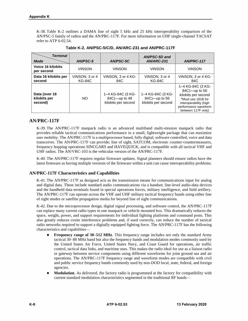
Appendix K
K-8 ATP 6-02.53 13 February 2020
K-38. Table K-2 outlines a DAMA line of sight 5 kHz and 25 kHz interoperability comparison of the
AN/PSC-5 family of radios and the AN/PRC-117F. For more information on UHF single-channel TACSAT
refer to ATP 6-02.54.
Table K-2. AN/PSC-5/C/D, AN/ARC-231 and AN/PRC-117F
Terminal
Mode AN/PSC-5 AN/PSC-5C
AN/PSC-5D and AN/ARC-231 AN/PRC-117
Voice 16 kilobits per second
VINSON VINSON VINSON VINSON
Data 16 kilobits per second
VINSON, 3 or 4 KG-84C
VINSON, 3 or 4 KG-84C
VINSON, 3 or 4 KG-84C
VINSON, 3 or 4 KG-84C
Data (over 16 kilobits per second)
NO 1–4 KG-84C (3 KG-
84C)—up to 48 kilobits per second
1–4 KG-84C (3 KG-84C)—up to 56
kilobits per second
1–4 KG-84C (3 KG-84C)—up to 56
kilobits per second *Must use 181B forinteroperability (high
performance waveformbetween 117F only)
AN/PRC-117F
K-39. The AN/PRC-117F manpack radio is an advanced multiband multi-mission manpack radio that
provides reliable tactical communications performance in a small, lightweight package that can maximize
user mobility. The AN/PRC-117F is a multiprocessor based, fully digital, software controlled, voice and data
transceiver. The AN/PRC-117F can provide; line of sight, SATCOM, electronic counter-countermeasures,
frequency hopping operations SINCGARS and HAVEQUICK, and is compatible with all tactical VHF and
UHF radios. The AN/VRC-103 is the vehicular version of the AN/PRC-117F.
K-40. The AN/PRC-117F requires regular firmware updates. Signal planners should ensure radios have the
latest firmware as having multiple versions of the firmware within a unit can cause interoperability problems.
AN/PRC-117F Characteristics and Capabilities
K-41. The AN/PRC-117F as designed acts as the transmission means for communications input for analog
and digital data. These include standard audio communications via a handset; line-level audio-data devices
and the handheld data terminals found in special operations forces, military intelligence, and field artillery.
The AN/PRC-117F can operate across the VHF and UHF military tactical frequency bands using either line
of sight modes or satellite propagation media for beyond line of sight communications.
K-42. Due to the microprocessor design, digital signal processing, and software control, the AN/PRC-117F
can replace many current radio types in one manpack or vehicle mounted box. This dramatically reduces the
space, weight, power, and support requirements for individual fighting platforms and command posts. This
also greatly reduces cosite interference problems and, if used correctly, can reduce the number of tactical
radio networks required to support a digitally equipped fighting force. The AN/PRC-117F has the following
characteristics and capabilities—
Frequency range of 30–512 MHz. This frequency range includes not only the standard Army
tactical 30–88 MHz band but also the frequency bands and modulation modes commonly used by
the United States Air Force, United States Navy, and Coast Guard for operations, air traffic
control, tactical data links, and maritime uses. This makes the radio ideal for use as a liaison radio
or gateway between service components using different waveforms for joint ground sea and air
operations. The AN/PRC-117F frequency range and waveform modes are compatible with civil
and public service frequency bands commonly used by non-DOD local, state, federal, and foreign
agencies.
Modulation. As delivered, the factory radio is programmed at the factory for compatibility with
current standard modulation characteristics segmented in the traditional RF bands—

Single-Channel Tactical Satellite Communications
13 February 2020 ATP 6-02.53 K-9
VHF low band. 30.00000–89.99999 MHz, frequency shift key. This makes the radio
interoperable with SINCGARS, AN/PRC-68, and other tactical radios of foreign and
domestic manufacture.
VHF high band. 90.00000–224.99999 MHz FM, AM, frequency shift key, amplitude shift
keying. In this frequency band, use the radio for air-to-air, air-to-ground, and ground-to-
ground voice and data communications using waveforms found in this band. The AN/PRC-
117F is compatible with various existing military aircraft, air-traffic-control radio
communications, and military air-to-ground data-link communications. The AN/PRC-117F
enables users that employ the radio to accomplish joint and civil-military liaison voice and
data with one radio. This is particularly important to the Army National Guard due to their
large role in defense support of civil authorities’ operations.
UHF band. 225.00000–511.99999 MHz. AM, frequency shift key, amplitude shift keying.
In this frequency band, use the AN/PRC-117F to perform air-to-air, air-to-ground, ground-to-
ground, fixed or mobile radio communications missions for voice and data modes. The
AN/PRC-117F is also compatible with electronic counter-countermeasures capable
equipment.
UHF SATCOM. 243.00000–270.00000 MHz and 292.00000–318.00000 MHz. In this
frequency range, AN/PRC-117F is fully compatible with single-channel TACSAT systems in
the dedicated channel or DAMA mode. The AN/PRC-117F also has full orderwire capability
and can send and receive data at a rate of 64 kilobits per second in a 25 kHz channel or 12
kilobits per second in a 5 kHz channel. Embedded in the radio hardware and software are
automatic requests for RETRANS of bad data packets and COMSEC. This key SATCOM
capability gives the radio a feature no other standard combat net radio has: the ability to
communicate beyond line of sight without RETRANS stations from the same radio package
used for line of sight communications.
K-43. The AN/PRC-117F operates in the following line of sight fixed frequency cipher text operating
capabilities and limitations—
VINSON-16 kilobits per second data rate, 25 kHz COMSEC KY-57 and KY-58 mode for secure
voice and data.
KG-84C compatible-(data only) supports voice only using 12 kilobits per second data rate in FM
and trellis code modulation from 30.00000–511.99999 MHz and AM mode from 90.00000–
511.99999 MHz. Available in all modes of UHF SATCOM.
TEKs-electronically loaded 128-bit transmission encryption keys used to secure voice and data
communications.
COMSEC key fill-TEKs, transmission security keys, and KEKs filled from the following
devices—
AN/PYQ-10, SKL.
KIK-30, really simple key loader.
KIV-7M.
K-44. The AN/PRC-117F can operate in HAVEQUICK I and II mode, utilizing frequency hopping from
225–400 MHz, providing compatibility with current airborne frequency hopping. The AN/PRC-117F can
also operate in SINCGARS frequency-hopping mode from 30.0000–87.975 MHz and supports SINCGARS
system improvement program or enhanced system improvement program features by placing the AN/PRC-
117F in either a net master or a net member mode.
K-45. The AN/PRC-117F can scan up to 10 line of sight fixed frequency or dedicated SATCOM radio voice
operation networks. The AN/PRC-117F does not scan HAVEQUICK, SINCGARS, or UHF DAMA
networks and does not use digital squelch. The plain text override feature of the VINSON and FASCINATOR
cipher text mode allows scanning combinations of cipher text and plain text networks.
AN/PRC-117F Data Capabilities
K-46. The AN/PRC-117F has the capability for use as a digital data-transmission device. This makes it easy
to interface data terminal equipment, computer workstations, and networking components. The AN/PRC-

Appendix K
K-10 ATP 6-02.53 13 February 2020
117F can send data transmission rates of 56 kilobits per second through SATCOM and 64 kilobits per second
ground-to-ground (line of sight).
K-47. With these data rates, the AN/PRC-117F would make data transmission at brigade and battalion
command posts and lower echelons fast enough to support lengthy database-to-database transfers. This would
not only improve operations but would also reduce system vulnerability to enemy intercept and detection.
The data rates support collaborative tools, video teleconferencing, and imagery transmission. (See Appendix
G for more information on data communications.)
AN/PRC-117G RADIO
K-48. The AN/PRC-117G radio is a software defined voice and data radio that supports in-field upgrades as
new capabilities emerge. The AN/PRC-117G radio has MUOS-ready hardware to extend communications
beyond line of sight. The AN/PRC-117G radio is capable of operating in a frequency range of 30 MHz to 2
GHz. The AN/PRC-117G radio can be configured for manpack, vehicular-mounted, or base station
operations. The AN/PRC-117G radio is capable of simultaneously transmitting Voice over Internet Protocol
and digital data on a single channel. Digital data transmitted via the AN/PRC-117G radio includes file
transfers, chat, streaming video, combat net radio, and position location information. The AN/PRC-117G
radio enables units to use IP routing to transmit medium to high bandwidth data traffic over tactical VHF,
UHF, and L-band radio networks. The AN/PRC-117G radio supports the following—
Advanced networking waveform.
181B-Dedicated Channel TACSAT.
SINCGARS.
HAVEQUICK II.
VHF and UHF.
AM and FM.
DAMA.
High performance waveform.
Integrated waveform.
K-49. The networking capabilities of the AN/PRC-117G radio can be enhanced using the RF-7800B
Broadband Global Area Network Terminals. The RF-7800B combined with the AN/PRC-117G provides
automatic and secure range extension, connection to out-of-range networks, and entry into the Internet or
remote private networks.
SINGLE-CHANNEL TACTICAL SATELLITE FIRE SUPPORT NETWORKS
K-50. The need for a digital link between the Advanced Field Artillery Tactical Data System, Initial Fire
Support Automation System, Forward Observer System, and non-fire support systems may require using
single-channel TACSAT networks in the distribution plan to support digital traffic. The commander decides
which network provides voice service, and which network carries data.
CORPS FIRE SUPPORT NETWORK
K-51. The purpose of the corps, fire support network is for clearing fires, which refers to the coordination
necessary when firing into an adjacent area of operations controlled by someone else. The coordination
ensures the area is under enemy control and no friendly forces in the area. The primary users of the network
include any of the following—
Corps fires cell.
Division fires cell.
Field artillery brigades.
Armored cavalry regiment fires cell.
Attack regiment fires cell.

Single-Channel Tactical Satellite Communications
13 February 2020 ATP 6-02.53 K-11
DIVISION FIRE SUPPORT NETWORK
K-52. The principal members of the division, fire support network include the division fires cell, field artillery
brigade, the brigade fires cell, fires battalion. The division, fire support network provides fire support
coordination and serves as an alternate for fire direction with elements in the division. The division command
post is typically the NCS. This network normally operates as a voice network.
K-53. The separate brigade has unique long haul communications requirements, which line of sight
operations cannot satisfy when dispersed over extended distances. These units deploy UHF single-channel
TACSAT terminals with their headquarters to provide connectivity for communications and situational
awareness with higher headquarters. The primary communications mode is secure voice.
FIELD ARTILLERY BRIGADE FIRE SUPPORT NETWORK
K-54. The field artillery brigade fire support network has the operations elements from the field artillery
brigade, field artillery brigade, fires battalion, and multiple launch rocket system battalions. The primary
purpose of this network is to provide a long-range link to subordinate field artillery elements. This network
is primarily a voice network but can transmit digital traffic between Advanced Field Artillery Tactical Data
System and other automated devices.
AIRBORNE AND AIR ASSAULT UNITS
K-55. The airborne and air assault units need en route communications to maintain a connection with the
sustaining base, other aircraft, and with the units that may already be in place. Airborne and air assault units
accomplishes this by using a secure en route communications package, which uses the Spitfire or a VHF and
UHF DAMA-capable single-channel TACSAT. The DAMA-capable single-channel TACSAT provides
communications in line of sight and SATCOM modes. The secure en route communications package supports
the commander and principal staff while en route to the area of operations. It supports ground operations
independently of the aircraft at staging areas and during joint task force initial ground operations.
K-56. Well-equipped, rapidly deployable units such as the global response force (GRF) are a vital part of the
Army’s efforts to be an agile and capable expeditionary force. Using the en route mission command capability
(EMC2), GRF commanders use in-flight internet capabilities while in flight to the drop zones of early entry
missions to gain real-time situational awareness and a comprehensive understanding of potential challenges.
The EMC2 enable commanders of GRF units to conduct command and control, and plan missions in the air,
while their Soldiers receive operational updates and watch full motion video of upcoming drop zones. The
EMC2 provides Soldiers the ability to understand a situation and take appropriate action before arriving at
their drop location, which enables the GRF to be more effective the moment the GRF arrives in operations.
K-57. Installed on C-17 aircraft, the EMC2 provide commanders of GRF units, connectivity to Warfighter
Information Network-Tactical. The EMC2 enables the GRF to stay connected to joint, coalition, or strategic
forces as they are traveling into a developing situation. The joint GRF consists of two components—
Air Force. The Air Force supplies and sustains the C-17 and C-130 aircraft.
Army (XVIII Airborne Corps). The XVIII Airborne Corps, primarily the 82d Airborne Division,
which has deployment-ready paratroopers and infantrymen, provides an immediate military
capability on the ground on short notice to any operation worldwide.
K-58. The EMC2 provides internet service, mission command applications, full motion video, intelligence
products, and collaborative planning tools, with a complete office suite of computers and voice phones
onboard an aircraft. It enables en route mission command, as the situation develops in the destination area of
operations, commanders can get updates, understand changes on the ground, and adjust their plan to
accommodate for the changes. EMC2 provides a transformation in the situational awareness and
effectiveness of the GRF in the first several hours of ground operations. Key components of EMC2 are—
Fixed install satellite antenna. The fixed install satellite antenna provides the internet connection
for the C-17. The stationary install satellite antenna provides the increased bandwidth that enables
employment of a new host of services on board the C-17 and improve the capability for GRF units
to plan and maintain critical situational awareness in the air.

Appendix K
K-12 ATP 6-02.53 13 February 2020
Key leader en route node. The key leader en route node provides airborne units with broadband
reach back capability, secure voice over Internet protocol communications between task force
commanders, combatant commanders, and communication between aircraft.
K-59. The EMC2 enables standard and high definition full motion video feeds from satellites, airplanes, and
drone displays on board the aircraft on light-emitting diode screens, integrated marquees, and an intercom
system. The EMC2 enables Soldiers to see the airfield and drop zone at the landing destination, providing
Soldiers enhanced situational awareness, and allowing Soldiers to better prepare for their mission. The EMC2
increases force mobility and versatility, allowing Soldiers easier access to the information they need to be
successful anytime, anywhere.

13 February 2020 ATP 6-02.53 Glossary-1
Glossary
The glossary lists acronyms and terms with Army, multi-service, or joint definitions,
and other selected terms. Where Army and joint definitions are different, (Army)
follows the term. Terms for which ATP 6-02.53 is the proponent manual (the authority)
are marked with an asterisk (*). The proponent manual for other terms listed in
parentheses after the definition.
SECTION I – ACRONYMS AND ABBREVIATIONS
ACES Automated Communications Engineering Software
ADP Army doctrine publication
ALE automatic link establishment
AM amplitude modulation
ANDVT advanced narrowband digital voice terminal
ATP Army techniques publication
BFT Blue Force Tracking
COMSEC communications security
COTS commercial off-the-shelf
CREW counter radio-controlled improvised explosive device electronic warfare
CSEL Combat Survivor Evader Locator
DAMA demand-assigned multiple access
dBi decibels isotropic
dBm decibels above one milliwatt
EA electronic attack
EMC2 en route mission command capability
EP electronic protection
EW electronic warfare
FBCB2 Force XXI Battle Command, Brigade and Below
FHMUX frequency hopping multiplexer
FM field manual; frequency modulation
G-2 assistant chief of staff, intelligence
G-6 assistant chief of staff, signal
GCC geographic combatant commander
GHz gigahertz
GPS Global Positioning System
GRF global response force
HF high frequency
IP internet protocol
JP joint publication

Glossary
Glossary-2 ATP 6-02.53 13 February 2020
JSIR joint spectrum interference resolution
JTIDS Joint Tactical Information Distribution System
KEK key encryption key
kHz kilohertz
KMI Key Management Infrastructure
KOAM Key Management Infrastructure operating account manager
LVT (2) Low Volume Terminal (2)
MBITR multiband inter/intra team radio
MHz megahertz
MIDS Multifunctional Information Distribution System
MUOS Mobile User Objective System
NATO North Atlantic Treaty Organization
NCO noncommissioned officer
*NCS net control station
NSA National Security Agency
PACE primary, alternate, contingency, and emergency
RCIED radio-controlled improvised explosive device
RETRANS retransmission
RF radio frequency
RT receiver-transmitter
S-2 battalion or brigade intelligence staff officer
S-6 battalion or brigade signal staff officer
SATCOM satellite communications
SC(T) signal command (theater)
SI strategic instruction
SINCGARS single-channel ground and airborne radio system
SKL simple key loader
STANAG standardization agreement (NATO)
TACSAT tactical satellite
TB technical bulletin
TEK traffic encryption key
TM technical manual
TRANSEC transmission security
UHF ultrahigh frequency
VHF very high frequency
WIN-T Warfighter Information Network-Tactical
SECTION II – TERMS
authentication
1. A security measure designed to protect a communications system against acceptance of a fraudulent
transmission or simulation by establishing the validity of a transmission, message, or originator.
(JP 3-50)

Glossary
13 February 2020 ATP 6-02.53 Glossary-3
call sign
Any combination of characters or pronounceable words, which identifies a communication facility, a
command, an authority, an activity, or a unit; used primarily for establishing and maintaining
communications. (JP 3-50).
communications network
An organization of stations capable of intercommunications, but not necessarily on the same channel.
(JP 6-0)
communications security
Actions designed to deny unauthorized persons information of value by safeguarding access to, or
observation of, equipment, material, and documents with regard to the possession and study of
telecommunications or to purposely mislead unauthorized persons in their interpretation of the results
of such possession and study. Also called COMSEC. (JP 6-0)
electromagnetic interference
Any electromagnetic disturbance, induced intentionally or unintentionally, that interrupts, obstructs, or
otherwise degrades or limits the effective performance of electronics and electrical equipment.
(JP 3-13.1)
electromagnetic spectrum
The range of frequencies of electromagnetic radiation from zero to infinity. It is divided into 26
alphabetically designated bands. (JP 3-13.1)
electronic attack
The division of electronic warfare involving the use of electromagnetic energy, directed energy, or
antiradiation weapons to attack personnel, facilities, or equipment with the intent of degrading,
neutralizing, or destroying enemy combat capability and is considered a form of fires. Also called EA.
(JP 3-13.1)
electronic protection
Division of electronic warfare involving actions taken to protect personnel, facilities, and equipment
from any effects of friendly or enemy use of the electromagnetic spectrum that degrade, neutralize or
destroy friendly combat capability. Also called EP. (JP 3-13.1)
electronic warfare
Military action involving the use of electromagnetic and directed energy to control the electromagnetic
spectrum or to attack the enemy. Also called EW. (JP 3-13.1)
electronic warfare support
Division of electronic warfare involving actions tasked by, or under direct control of, an operational
commander to search for, intercept, identify, and locate or localize sources of intentional and
unintentional radiated electromagnetic energy for the purpose of immediate threat recognition,
targeting, planning, and conduct of future operations. Also called ES.(JP 3-13.1)
emission control
The selective and controlled use of electromagnetic, acoustic, or other emitters to optimize command
and control capabilities while minimizing, for operations security: a. detection by enemy sensors; b.
mutual interference among friendly systems; and/or c. enemy interference with the ability to execute a
military deception plan. (JP 3-13.1)
line of sight
The unobstructed path from a Soldier’s weapon, weapon sight, electronic sending and receiving
antennas, or piece of reconnaissance equipment from one point to another. (ATP 2-01.3)
message
Any thought or idea expressed briefly in a plain or secret language and prepared in a form suitable for
transmission by any means of communication. (JP 6-0)

Glossary
Glossary-4 ATP 6-02.53 13 February 2020
*net control station
A communications station designated to control traffic and enforce circuit discipline within a given
net. Also called NCS.
procedure word
A word or phrase limited to radio telephone procedure used to facilitate communication by conveying
information in a condensed standard form. Also called proword. (JP 3-09.3)
*radio silence
The status on a radio network in which all stations are directed to continuously monitor without
transmitting, except under established criteria.
signal operating instructions
A series of orders issued for technical control and coordination of the signal communication activities
of a command. (JP 6-0)

13 February 2020 ATP 6-02.53 References-1
References
All URLs accessed on 27 December 2019.
REQUIRED PUBLICATIONS These documents must be available to the intended users of this publication.
DOD Dictionary of Military and Associated Terms. November 2019.
ADP 1-02. Terms and Military Symbols. 14 August 2018.
RELATED PUBLICATIONS These documents contain relevant supplemental information.
DEPARTMENT OF DEFENSE PUBLICATIONS
Most Department of Defense Instructions are available online: https://www.esd.whs.mil/DD/
DODI 4650.01. Policy and Procedures for Management and Use of the Electromagnetic Spectrum.
9 January 2009.
JOINT PUBLICATIONS
Most joint publications are available online: https://www.jcs.mil/doctrine.
JEL+ Website: https://jdeis.js.mil/jdeis.
CJCSI 3320.02F. Joint Spectrum Interference Resolution. 8 March 2013.
CJCSI 6250.01F. Department of Defense Satellite Communications. 26 February 2019.
CJCSM 3320.01C Joint Electromagnetic Spectrum Management Operations in the Electromagnetic
Operational Environment. 14 December 2012.
CJCSM 3320.02D. Joint Spectrum Interference Resolution (JSIR) Procedures. 3 June 2013.
JP 3-09.3. Close Air Support. 10 June 2019. (JEL+)
JP 3-13.1. Electronic Warfare. 8 February 2012. (JEL+)
JP 3-50. Personnel Recovery. 2 October 2015. (JEL+)
JP 6-0. Joint Communications System. 10 June 2015.
ARMY PUBLICATIONS
Most Army doctrinal publications are available online: https://armypubs.army.mil.
AR 5-12. Army Use of the Electromagnetic Spectrum. 16 February 2016.
AR 25-1. Army Information Technology. 15 July 2019.
AR 25-2. Army Cybersecurity. 4 April 2019.
AR 380-5. Army Information Security Program. 22 October 2019.
AR 380-27. Control of Compromising Emanations. 22 July 2014.
AR 380-40. Safeguarding and Controlling Communications Security Material (U). 9 July 2012.
AR 380-53. Communications Security Monitoring. 23 December 2011.
ATP 1-02.1. Brevity - Multi-Service Tactics, Techniques, and Procedures for Multi-Service Brevity
Codes. 20 June 2018.
ATP 2-01.3. Intelligence Preparation of the Battlefield. 1 March 2019.

References
References-2 ATP 6-02.53 13 February 2020
ATP 3-05.60. Special Operations Communications System. 30 November 2015.
ATP 3-12.3. Electronic Warfare Techniques. 16 July 2019.
ATP 5-19. Risk Management. 14 April 2014.
ATP 6-02.54. Techniques for Satellite Communications. 5 June 2017.
ATP 6-02.60. Tactical Networking Techniques for Corps and Below. 9 August 2019.
ATP 6-02.70. Techniques for Spectrum Management Operations. 16 October 2019.
ATP 6-02.72. Multi-Service Tactics, Techniques, and Procedures for Tactical Radios. 19 May 2017.
FM 6-02. Signal Support to Operations. 13 September 2019.
FM 6-27. The Commander’s Handbook on the Law of Land Warfare. 7 August 2019.
TB 380-41. Security: Procedures for Safeguarding, Accounting, and Supply Control of COMSEC
Material. 15 August 2013.
TC 6-02.6. Grounding Techniques for Tactical Equipment and Systems. 22 November 2017.
TC 9-64. Communications-Electronics Fundamentals: Wave Propagation, Transmission Lines, and
Antennas. 15 July 2004.
OTHER PUBLICATIONS Manual of Regulations and Procedures for Federal Radio Frequency Management. (Redbook).
September 2017.
https://www.ntia.doc.gov/files/ntia/publications/ntia_manual_september_2017_revision.pdf.
NATO STANAG 4538. Technical Standards for an Automatic Radio Control System (ARCS) for HF
Communication Links. 12 November 2015.
NATO standardization agreements are available on the NATO Standards Organization Website
https://nso.nato.int (validated user account required).
United States Strategic Command SI 714-04. Satellite Communications. 14 October 2014. (Requires
DOD-approved e-mail certificate login and a validated USSTRATCOM user account.)
https://lynx.usstratcom.mil/sites/publications/Lists/Publications/AllItems.aspx.
RECOMMENDED READINGS
ADP 3-0. Operations. 31 July 2019.
ADP 6-0. Mission Command: Command and Control of Army Forces. 31 July 2019.
ADP 7-0. Training. 31 July 2019.
AR 25-6. Military Auxiliary Radio System and Amateur Radio Program. 9 October 2019.
ATP 6-02.71. Techniques for Department of Defense Information Network Operations. 30 April 2019.
ATP 6-02.75. Techniques for Communications Security Operations. 17 August 2015.
FM 3-0. Operations. 6 October 2017.
FM 3-12. Cyberspace and Electronic Warfare Operations. 11 April 2017.
PRESCRIBED FORMS None
REFERENCED FORMS Unless otherwise indicated, Department of the Army forms are available on the Army Publishing
Directorate Website. https://armypubs.army.mil.
DA Form 2028. Recommended Changes to Publications and Blank Forms.

13 February 2020 ATP 6-02.53 Index-1
Index
Entries are by paragraph number.
A
AB-1386/U, 8-108
ACES. See Automated Communications Engineering Software, See
Automated Communications Engineering Software
ALE. See automatic link establishment
AM. See amplitude modulation
amplitude modulation, B-65
AN/ARC-186, 7-13
AN/ARC-201, 7-2
AN/ARC-210, 7-6
AN/ARC-220, 7-9
AN/ARC-231, 7-11
AN/PRC-117F, K-39
AN/PRC-117G, K-48
AN/PRC-148, 5-1
AN/PRC-148C, 3-104
AN/PRC-150, 3-71
AN/PRC-152A, 5-9
AN/PRC-155, 3-107
AN/PRC-158, 5-14
AN/PRC-160, 3-109
AN/PRC-161, 6-14
AN/PRC-162, 3-108
AN/PRC-163, 3-103
AN/PSC-11. See Single-Channel Anti-Jam Man-Portable terminal
AN/PSC-5, K-25
AN/PSC-5C, K-35
AN/PSC-5D, K-37
AN/VRC-100, 3-68
antenna gain, 8-42
antenna selection, C-1 directivity, C-19 gain, C-11 planning, C-24 polarization, C-17
procedures, C-4 UHF and VHF, C-14
antenna techniques, overview, 8-1
antenna, HF, location, 8-5
antennas broadband omnidirectional,
8-104COM-201B, 8-105 field repair, 8-128, J-1
guys, 8-135, J-8masts, 8-
136, J-9 whip, 8-129, J-2 wire, 8-131, J-4
length, 8-58 orientation, 8-60 satellite communications,
8-120types, 8-69
inverted L, 8-84 inverted vee, 8-76 long wire, 8-80 NVIS, 8-75, 8-87 sloping V, 8-83 V, 8-78 vertical half-rhombic,
8-80whip, 8-96
VHF and UHF, 8-95 VHF half-rhombic, 8-110
austere environments cold weather, D-1 desert, D-43 jungle, D-20 mountains, D-57 nuclear, D-60 urban, D-27
authentication, 10-59
Automated Communications Engineering Software, 1-26, 9-14
automatic link establishment, 3-7
B
battalion maneuver, 2-14 signal, 2-7
BCT. See brigade, maneuver
Blue Force Tracking, 3-92
brigade, 2-4 maneuver, 2-13 signal, 2-5
brigade combat team, 2-13
C
call procedures, I-6
CJSMPT. See Coalition Joint Spectrum Management Planning Tool
Coalition Joint Spectrum Management Planning Tool, 1-30
Combat Survivor Evader Locator, 1-41
combatant commander communications team, 2-1
command post, tactical, 2-18
communications-electronics operating instructions, 9-24
compromise, F-1 determination, F-2 recovery, F-3
COMSEC, key distribution, 9-8
corps, 2-10
counter radio-controlled improvised explosive device electronic warfare, 10-96
CREW. See counter radio-
controlled improvised explosive device electronic warfare
CSEL. See Combat Survivor
Evader Locator
D
DAGR. See Defense Advanced Global Positioning System Receiver
DAMA. See demand-assigned
multiple access
data

Index
Index-2 ATP 6-02.53 13 February 2020
asynchronous and synchronous, G-5
baud rate, G-3 binary, G-1 HF modems, G-7
Defense Advanced Global Positioning System Receiver, 3-59
demand-assigned multiple access, K-12
diffraction, B-54
division, 2-11
E
EA. See electronic attack
electromagnetic interference, 10-101
electronic attack, 10-4
electronic protection, 10-6, 10-47, 10-66
electronic warfare, 10-1 responsibilities
commander, 10-15 staff, 10-18
electronic warfare support, 10-2
EMI. See electromagnetic interference
emission control, 10-23, 10-45
encryption, 10-60
EP. See electronic protection
ES. See electronic warfare support
F
Falcon III, 3-109, 5-9
Falcon IV, 5-14
FBCB2, 3-97
forward error correction, G-11
G
ground effects, 8-45
ground, types, 8-48
I
ICEPAC. See ionospheric
communications enhanced profile analysis and circuit prediction
integrated waveform, K-17
ionospheric communications enhanced profile analysis and circuit prediction, C-30
J
JACES. See Joint Automated Communications-Electronics Operating Instruction System
jamming, 10-67 overcoming, 10-75 recognizing, 10-70
JENM. See Joint Enterprise Network Manager
Joint Automated Communications-Electronics Operating Instruction System, 1-26
Joint Capabilities Release, 3-98
Joint Enterprise Network Manager, 1-28
joint spectrum interference resolution, 10-103
joint tactical information distribution system, 6-9
JSIR. See joint spectrum interference resolution
JTIDS. See joint tactical
information distribution system
Julian Date, E-1
K
key management infrastructure, 9-1
KMI. See key management infrastructure
L
land mobile radio, 1-35
link geometry, 10-29
loadsets, 9-26
lowest usable frequency, B-44
M
management client, 9-13
management, network, 1-24
maximum usable frequency, B-44
MBITR, 5-1
MGC. See management client
MicroLight, 3-62
MIDS. See Multifunction Information Distribution System
MMR. See multiband multi-mission radio
modulation, B-64
Multiband Multi-Mission Radio, K-37
Multifunctional Information Distribution System, 6-2
N
Nett Warrior, 3-105
Network Operations Management System, 1-19
networks administrative and logistics,
A-9closing, I-12 command, A-6 entry, I-10 fire direction, A-13 fire support, K-50 fire surveillance, A-14 frequency modulation, A-1 HF data, A-21 high frequency, A-17 leaving, I-11 medical, A-11 opening, I-7 operations and intelligence,
A-10radio checks, I-9 sustainment area
command, A15
networks, tactical, 1-9 lower tier, 1-12 upper tier, 1-11
O
OE-254, 8-104
OE-303, 8-110
P
PACE plan, 10-24
path loss, B-50
phonetic alphabet, I-1
planning, communications, 10-21
polarization, 8-16 elliptical, 8-26 horizontal, 8-23 vertical, 8-18
procedure words, I-5
pronunciation, numerals, I-2
propagation direct wave, B-23 ground reflected wave, B-24 ground wave, B-22
characteristics, B-26 skywave, B-30 surface wave, B-25
proword. See procedure words

Index
13 February 2020 ATP 6-02.53 Index-3
R
radiation fields, 8-13
radiation patterns, 8-15
radio waves, B-19
radios airborne, 7-1 capabilities, 1-32 components, B-1
receiver, B-12 transmitter, B-5
high frequency, 3-63 tactical, 1-1
in Army operations, 1-2 manpack, 3-107 networking ground radio,
3-108software-defined, 3-99 terrestrial and satellite
communications, 1-5
RC-1476, 7-3
RC-1477, 7-4
reflected wave, B-51
RF-5800H, 3-66
S
SCAMP. See Single-Channel Anti-Jam Man-Portable terminal
security, signal, 10-43
Shadowfire, K-35
signal command (theater), 2-3
signal operating instructions, 9-24
Simple Key Loader, 9-33
SINCGARS, 3-2 anti-jamming, 10-78 cosite interference, H-1
mitigation, H-6 Julian date, E-1 synchronization time, E-4 ZULU time, E-6
Single-Channel Anti-Jam Man-Portable terminal, K-21
single-channel tactical satellite, 3-90, K-1
single-sideband, 3-67, B-70
SKL. See Simple Key Loader
soil condition, 8-50
special operations forces, 2-16
SPEED. See system planning, engineering, and evaluation device, See Systems Planning, Engineering, and Evaluation Device
Spitfire, K-25 retransmission, K-30
SSB. See single-sideband
Systems Planning, Engineering, and Evaluation Device, 1-31, C-25
T
TACSAT, K-1 airborne and air assault,
K-55electronic warfare, 10-85 fire support networks, K-50
corps, K-51 division, K-52 field artillery brigade,
K-54planning, K-4 UHF, K-18
tactical digital information link-joint, 6-5
Tactical Internet Management System, 1-29
TADIL-J. See tactical digital
information link-joint
take-off angle, 8-44
TIMS. See Tactical Internet Management System
transmission paths, B-3
W
waveforms, 1-18, 4-1 applications, 4-10 lower tier
integrated waveform, 4-8 link 16, 4-2 MUOS, 4-5 SINCGARS, 4-3 TACSAT, 4-4

This page intentionally left blank.
ATP 6-02.53 13 February 2020
By Order of the Secretary of the Army:
JAMES C. MCCONVILLEGeneral, United States Army
Chief of Staff
Official:
DISTRIBUTION: Distributed in electronic media only (EMO).
KATHLEEN S. MILLER Administrative Assistant
to the Secretary of the Army2003702

This page intentionally left blank.


PIN:105891-000