atomic force microscopy indentation of living cells - …formatex.info/microscopy4/433-440.pdf ·...
TRANSCRIPT
Atomic Force Microscopy indentation of living cells
Lucel Sirghi
Department of Physics, Alexandru Ioan Cuza University of Iasi, Bd. Carol I 11, 700506 Iasi, Romania
Atomic Force Microscopy (AFM) indentation on living cells in physiological medium is a well established technique used
for investigation of the cell mechanical properties at nanoscale. However, interpretation of the experimental data obtained
in such experiments is rarely a trivial task. This is happening because living cells have a complex response to the applied
mechanical stress, response that is governed by the plastic, elastic, viscosity and adhesion properties of the cells. This
chapter presents recent results obtained in AFM indentation of living eukaryotic cells. Contributions of elastic and
adhesion properties of the cells to the indentation loading and unloading force curves are discussed. A special attention is
devoted to the role of adhesion force in interpretation of force curve data. It is shown that the use of an appropriate
indentation model may provide information on the cell cytoskeleton elasticity and the work of adhesion of the cell
membrane to the surface of the AFM probes.
Keywords atomic force microscopy; nanoindentation; cytoskeleton elasticity modulus; cell membrane adhesion, living
cell mechanics
1. Introduction
Investigation of mechanical properties of living cells at nanometric scale is crucial for understanding the mechanical
interaction of cells with various materials. At this scale most of the surfaces are rough, having small features that may
affect crucially their interaction with living tissue. In contact with implanted devices, cells interact with surfaces with
nanoscale features in topography and chemistry. Therefore, the information on the living cell elasticity and adhesion at
nanoscale are very important for engineering of implanted device surfaces. The mechanical parameters of living cells at
nanoscale are also important for our understanding of cell interaction with nanoparticles, a key issue in nanotoxicology
[1] and nanomedicine [2]. Thus, the mechanical properties of cells at nanoscale are key parameters for the mechanism
of endocytosis of small objects, as viruses [3] and nanoparticles [4]. Measurements of cell mechanical properties at
nanoscale may also provide useful medical information, as for example in the case of the kidney stone formation [5] or
in the case of nanoparticle use as drug-delivery platform [6]. Knowledge of the mechanical properties of the cells at
nanoscale is also important for the practical purpose of AFM imaging of living cells. In contact mode AFM, the cells
comply with the AFM tip shape on a contact area that depends on the cell stiffness, tip geometry, adhesion force, and
the external force applied to the AFM probe [7]. These parameters are critical for AFM scanning of live cells because
they determine the image resolution. Moreover, large adhesion and/or externally-applied forces may cause large cell
deformations and cell membrane damages [8].
Atomic force microscopy (AFM) indentation is one of a variety of techniques that are currently used for
measurement of the mechanical proprieties of living cells. These techniques include micropipette aspiration, optical
tweezers, magnetic twisting cytometry, and fluid shear flow [9]. While some of the techniques determines the cell
response to a mechanical stress applied to the whole cell (as in micropipette aspiration and fluid shear flow), other
determines the mechanical response of the cell to a locally applied stress (as in AFM indentation, optical tweezers, and
magnetic twisting cytometry). Comparing to other local measurement techniques, the AFM has the advantage of
imaging of the indented cells with a resolution of tens of nanometers, a very good control of the probe position and
loading/unloading speed, and the use of different probe geometries (spherical, pyramidal, conical). However, the
interpretation of the experimental data obtained in AFM indentation of living cells is often difficult. This is happening
because the response of the living cells to the indentation is governed by the plastic, elastic, viscosity and adhesion
properties of the cells. This chapter presents the fundamental experimental and theoretical considerations on the AFM
indentation of living cells. Section 2 presents the main experimental aspects of force-displacement curve data acquired
in the AFM indentation experiments, while section 3 presents the theoretical models used in interpretation of the force-
displacement curves obtained in deep indentations of living cells. A special attention is devoted to the effect of adhesion
on the force-displacement curves. The theoretical indentation model developed recently by Sirghi et al [10-12] is
described in detail and used for processing of experimental force-displacement curves to obtain information on the cell
cytoskeleton elasticity and the work of adhesion of the cell membrane to the surface of the AFM probes.
Microscopy: Science, Technology, Applications and Education A. Méndez-Vilas and J. Díaz (Eds.)
©FORMATEX 2010 433
______________________________________________
2. AFM nanoindentation of living cells. How and what is measured?
2.1 Principle of the Atomic Force Microscope
The atomic force microscope [13] is an instrument based on detection of the interaction force between a microscopic tip
and a sample surface. The attribute “atomic” comes from the fact that the interaction region between the tiny tip (radius
of 10 nm) and sample involves a limited number of atoms. The AFM probe, consisting of a flexible cantilever with a
sharp tip at its end (usually made of silicon or silicon nitride), is the most important part of the AFM system. The force
is sensed by a laser beam reflected by the top of the cantilever. Any small force acting on the tip deflects the cantilever
and the laser beam, the deviation being measured by a photodiode. When it is working in contact mode, the AFM probe
raster scans the sample surface under a constant repulsive interaction force. The height profile along each scanning line
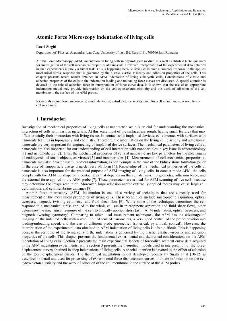
is acquired and used to reconstruct the 3D topography image of the surface. Figure 1 a) shows schematically the AFM
setup used for imaging and indentation of living cells grown on a stiff substrate (the size of the AFM probe and living
cell are exaggerated to provide a better illustration of the setup). The sample (living cells on the substrate) is loaded on a
liquid cell. On the top of the liquid cell is immersed the AFM probe mounted on a glass prism. A laser beam is reflected
by the top of the cantilever of the AFM probe and the reflected and refracted beam illuminates a four-quadrant
photodiode. In absence of any force acting on the tip of the AFM probe (when the tip is far from the sample surface) the
laser beam hit the photodiode in the middle, so there is no difference in the signals provided by the upper and bottom
parts of the photodiode, thus the force signal provided by the differential operational amplifier (OA) is zero. When the
tip is interacting by a small force with the sample surface, the cantilever and the reflected laser beam are deflected, so
that the photodiode parts are unequally illuminated, which results in certain nonzero value of the force signal yield by
the operational amplifier. The AFM instrument is capable of measuring tiny forces with a resolution of about 10 pN.
The force resolution is limited by the force constant and thermal noise of the cantilever of the AFM probe. Soon after its
invention, it became clear that the instrument can be use for scientific investigations of soft biologic samples in
physiologic medium [14]. Thus, the AFM instruments working in liquid environment were used for imaging
biomolecules, living eukaryotic cells, bacteria, and viruses. Moreover, the good control of AFM probe position allowed
development of force spectroscopy techniques for investigation of mechanical properties of biomolecules (AND,
collagen, fibrinogen, etc.) and strength of specific (ligand-receptor, antibody-antigen) binding forces [15].
2.2 Force-displacement curves measured in AFM indentations of living cells
Indentation is a well-established technique used in testing hardness and elasticity of materials [16]. The advent of
atomic force microscope [13] and depth-sensing nanoindenter apparatus [17] allowed a dramatic decrease of the
indentation dimensions along with a corresponding decrease of the indentation force. Both techniques are based on
measurements of the variation of the indentation force during displacement of an indenter. While the nanoindenter
apparatus allow a better control of the indentation force and indenter displacement, the atomic force microscope offers
the unique advantages of imaging of the samples topography, mapping the measured mechanical properties over the
investigated surface of the sample, and applying very small indentation forces (down to 10 pN). The main drawback of
the AFM indentation technique is related to the compliance of the AFM probe. In the AFM indentation, the indentation
force is applied to the indenter (the tip of the AFM probe) through a flexible cantilever [Figure 1 b)]. In practice, the
indentation is performed by moving of the cantilever base and measuring the corresponding indenting force (deflection
of the cantilever). Thus, the dependence of the indentation force, P, on the cantilever base displacement (z) during
loading and unloading parts of the indentation is measured and used to determine the mechanical properties of the
sample surface. Due to the cantilever deflection, δ, the displacement of the indenter (the AFM tip), h, is smaller than z.
Figure 1 b) illustrates the relation between these displacements, which is
hz += δ , (1)
where the displacements are taken positive in the direction of loading movement of the indenter. The cantilever
deflection depends on indentation force according the equation:
k
P=δ , (2)
where P > 0 if it is repulsive and P < 0 if it is attractive, and k is the force constant of the cantilever (it characterizes the
cantilever flexibility). In the AFM indentation experiments, the AFM probe is moved with constant speed, dz/dt =
const., while the speed of indenter displacement (dh/dt) is not controlled. The value of k should be carefully chosen to
match the stiffness of the sample surface (see the section 3.2 for the definition of the surface stiffness). If k is much
larger than the surface stiffness, h ≅ z, and δ ≅ 0, which means there is no detection of force. On the other hand, if k is
much smaller than the surface stiffness, δ ≅ z and h ≅ 0, which means there is no indentation because the applied force
is too small. This latter case corresponds to force curves acquired on stiff substrates (glass, mica, silicon) and is used for
calibration of the deflection signal.
Microscopy: Science, Technology, Applications and Education A. Méndez-Vilas and J. Díaz (Eds.)
434 ©FORMATEX 2010
______________________________________________
a) b)
Fig. 1 a) Sketch of the AFM setup used for study of living cells in physiologic medium. The liquid cell is fixed and contains the
sample and the measurement medium, while the AFM probe is moved by the AFM scanner. The laser beam reflected by the
cantilever of the AFM probe is used for the force detection. b) Sketch illustrating the relationship between vertical displacements of
the AFM probe (z) and tip (h) and the deflection of the cantilever (δ). The arrows indicate the positive direction of the displacements.
The stiffness of living cells in contact with the sharp tip of the AFM probe is estimated to be around 10-3 N/m (see
the theoretical considerations in the next section), which means that the AFM indentation of living cells should be
performed by AFM probes with very flexible cantilevers (commercially available AFM probes may have cantilevers
with k as low as 10-2 N/m).
In AFM indentation experiments the AFM probe is moved downwards versus the fixed sample (alternatively, the
sample is moved upwards towards the fixed AFM probe) and the loading curve of cantilever deflection versus the probe
displacement is acquired. After loading, the AFM probe is retracted and the unloading curve of cantilever deflection
versus the probe displacement is acquired. Then, these row experimental data are processed to obtain the curves of
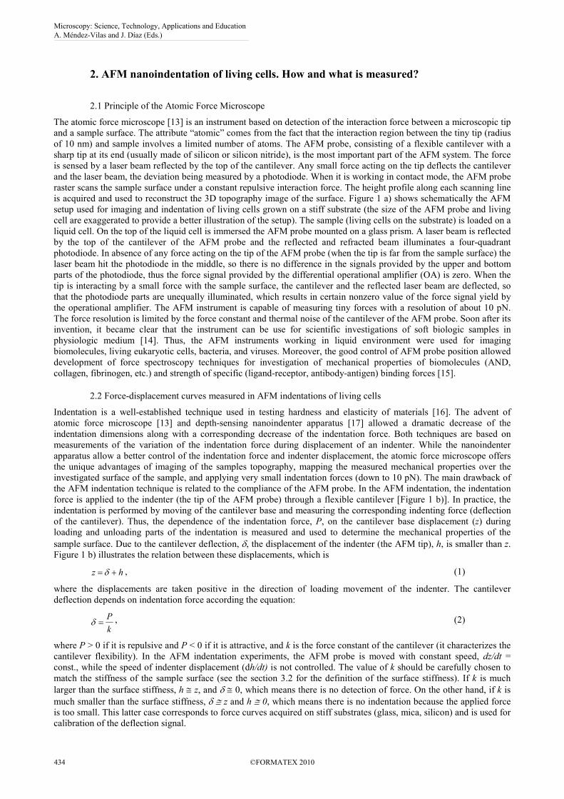
indentation force versus the AFM tip displacement. Figure 2 presents schematically a typical force curve obtained in a
living cell indentation affected by adhesion. While the AFM probe is moved downwards and the AFM tip is far from
the cell surface, the interaction force is zero (position 1). Then, the AFM tip is impinging on the cell with a positive
indentation force (position 2). After loading, the AFM probe is retracted and the impinging force is decreasing. Due to
the tip-cell adhesion, the interaction force becomes negative (position 3 in Fig. 2) and the tip is pulling up the cell.
a) b)
Fig. 2 a) Sketch of a typical force versus the AFM tip displacement acquired in indentation of a living cell. b) States of the AFM
probe corresponding to the three points figured on the force curve. It is assumed that the indentation is affected by the adhesion force
between the AFM tip and cell membrane.
Microscopy: Science, Technology, Applications and Education A. Méndez-Vilas and J. Díaz (Eds.)
©FORMATEX 2010 435
______________________________________________
After complete detachment, the interaction force becomes zero and the distance between the tip and sample
increases. In practice, there are indentations in which the adhesion is negligible, when no negative values of force are
noticed during the retraction of the AFM probe. On the other hand, in some indentation experiments the adhesion force
is important. The variation of adhesion force is not always continuous. Sudden decreases of adhesive force can be
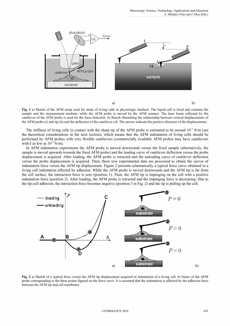
observed on some experimental force curves due to tethering of cell membrane to the AFM tip. Figure 3 presents a
comparison between two force curves acquired in indentations of living mouse fibroblast Balb/c3T3 clone A31-1-1
cells with commercial Si3N4 AFM probes (Microlever MLCT-AUNM from Veeco) with pyramidal tips (pyramid angle
of 35°) and flexible cantilevers (nominal constant of 10 mN/m) [11]. While the force curve showed in Fig. 3 a) presents
a continuous variation of the adhesion force, the force curve presented in Fig. 3 b) shows three detachment events, each
characterized by a jump of the force of about 10 pN. The adhesion force is also a cause of the hysteresis observed in
living cell indentations. While the adhesion favours the movement of the indenter during loading, it opposes the
indenter movement during unloading. Other cause of hysteresis is the cell viscosity. However, this effect can be
diminished by using low values of loading and unloading speed [11].
a) b)
Fig. 3 Force versus displacement force curves showing a) continuous and b) discontinuous variations of adhesive force.
Discontinuities of adhesive force variation are due to cell membrane tethering. Three detachment events (D1, D2, and D3) are seen on
the plot b).
3. Theoretical considerations
3.1 Mechanical response of living cells to the indentation tests.
Living cells indentation is theoretically treated at level of the mechanical response of cell membrane and cytoskeleton to
the indentation. These two components of the cell are regarded as continuum (their nanoscopic structures are ignored)
isotropic and homogeneous elastic materials. Therefore, the elastic forces generated by indentation deformations of the
cell membrane and cytoskeleton are taken into consideration. However, the elastic forces caused by the cell membrane
indentation are negligible small comparing to the elastic force caused by the cytoskeleton deformation. During
indentation, the cell membrane suffers stretching and bending deformations. The elastic force opposing such
deformations of the membrane may be neglected by comparison with the elastic force of cytoskeleton. This is because,
in absence of pre-stress tension, the cell membrane is not smooth [18] and it may stretch under the action of the AFM
tip without opposing a noticeable elastic force. When there is an isotropic pre-stress tension into the cell membrane, the
force opposing the membrane deformation can be important [19]. In the followings, the pre-stress tension is considered
low enough to neglect the force required to stretch the cell membrane in the cell indentation. The force required to bend
the cell membrane is also negligible because of low value of the bending rigidity of the cell membrane [18]. Then, the
cell indentation force is considered to be determined mainly by the elastic force of the cell cytoskeleton. This
assumption is justified by the drastic effect of cell elasticity induced by cytoskeleton disruption drugs [20].
3.2 Elastic indentations with negligible adhesion
The elasticity of a continuum and homogeneous material is usually investigated by measuring the material deformation,
∆l, as response to applied force, P, where l is the length of the tested material along the direction of the applied force.
Thus, the stiffness of the material is easily estimated as:
dl
dPS = , (3)
However, the measured stiffness is not a suitable parameter for characterization of material elasticity because its
value depends on the deformation geometry. Therefore, dl and P are normalized to l and A (A is the surface area on
Microscopy: Science, Technology, Applications and Education A. Méndez-Vilas and J. Díaz (Eds.)
436 ©FORMATEX 2010
______________________________________________
which the force is applied), respectively. Then, the material elasticity is investigated by measuring the strain, ε = dl/l, response of the material to the applied stress, σ = P/A. For perfectly elastic materials, this relationship has been
established by Hook to be linear:
εσ ⋅= E , (4)
where E is a material parameter called the Young’s modulus of elasticity. The value of E allows the estimation of the
force required to generate a certain deformation of the material. Thus, for the most simple case of a tensile test, when an
elongation force, P, is applied to a string of material with length l and cross section area A, the value of E is equal with
the value of the elongation stress (P/A) required to double the string length (∆l/l=1). For example, to double the length
of a string made of rubber it is required a stress of about 108 Pa (1 Pa = 1N/m
2), which means that E for rubber is about
100 MPa.
For the case of indentation test, which is used to locally determine the elasticity of a material surface, determination
of E is much less simple. In this test, a compression force, P, is applied via an indenter on a small contact area Ac of the
material surface and the local displacement of the material surface, h, is measured (Fig. 4). Usually, the indenter is
made of a much harder material than the indented probe, so the deformation of the indenter itself is negligible. For axis
symmetrical indenters, Sneddon [21] has showed that the surface stiffness of the material, S = dP/dh, depends on E and
the radius, rc, of the contact surface between the indenter and the material )/( πcc Ar = according to the following
equation:
cr
E
dh
dP⋅
−⋅=
212
ν. (5)
where ν is a dimensionless coefficient called the Poisson factor of the material. This parameter describes the effect of
material deformation along the direction perpendicular to the direction of the applied stress. For incompressible
materials this transversal deformation results from the material tendency to keep its volume constant. The transversal
dimension of an elastic body increases as results of compression and decreases as result of elongation. The relative
variation of volume as result of deformation is ∆V/V = (1-2ν)⋅ε. Therefore, for incompressible materials (as living cells
are often considered), ν = 0.5, so that ∆V/V = 0. If the indentation is performed with a flat indenter, the contact radius
does not change during the indentation (rc = r, where r is the indenter radius) and the applied force varies linearly with
the surface displacement:
hrE
P ⋅⋅−
= 21 2ν
. (6)
This equation shows that the indentation force can be very small for small indenters and displacement values. For
living cells, which are among the softest natural materials, this force can be as low as 10 pN (which is at the limit of the
AFM force measurement resolution). Obviously, for stiffer materials the force is larger (ex. P = 1 nN for rubber). These
estimations were done for 2r = 100 nm and h = 10 nm.
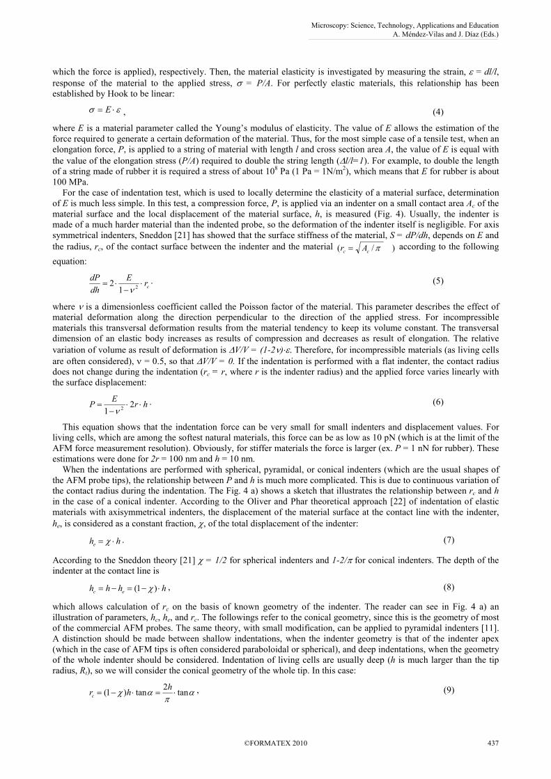
When the indentations are performed with spherical, pyramidal, or conical indenters (which are the usual shapes of
the AFM probe tips), the relationship between P and h is much more complicated. This is due to continuous variation of
the contact radius during the indentation. The Fig. 4 a) shows a sketch that illustrates the relationship between rc and h
in the case of a conical indenter. According to the Oliver and Phar theoretical approach [22] of indentation of elastic
materials with axisymmetrical indenters, the displacement of the material surface at the contact line with the indenter,
he, is considered as a constant fraction, χ, of the total displacement of the indenter:
hhe ⋅= χ . (7)
According to the Sneddon theory [21] χ = 1/2 for spherical indenters and 1-2/π for conical indenters. The depth of the indenter at the contact line is
hhhh ec ⋅−=−= )1( χ , (8)
which allows calculation of rc on the basis of known geometry of the indenter. The reader can see in Fig. 4 a) an
illustration of parameters, hc, he, and rc. The followings refer to the conical geometry, since this is the geometry of most
of the commercial AFM probes. The same theory, with small modification, can be applied to pyramidal indenters [11].
A distinction should be made between shallow indentations, when the indenter geometry is that of the indenter apex
(which in the case of AFM tips is often considered paraboloidal or spherical), and deep indentations, when the geometry
of the whole indenter should be considered. Indentation of living cells are usually deep (h is much larger than the tip
radius, Rt), so we will consider the conical geometry of the whole tip. In this case:
απ
αχ tan2
tan)1( ⋅=⋅−=h
hrc, (9)
Microscopy: Science, Technology, Applications and Education A. Méndez-Vilas and J. Díaz (Eds.)
©FORMATEX 2010 437
______________________________________________
where α is the cone angle of the AFM tip (Fig. 4). Recently, Sirghi and Rossi [12] have shown that, in order to account
for the effects of the adhesion force and finite curvature radius of the indenter apex in deep indentations, this equation
should be modified to:
αχ tan)1(0 ⋅−+= hrrc , (10)
The effects of adhesion and finite curvature radius are described by the parameter r0 of which value depends on the
adhesion force, Fa, and curvature radius of the indenter apex, Rt. The plots in Figure 4 b) presents the dependence of rc
on h at loading and unloading part of AFM indentations of a soft and elastic material (a polydimethylsiloxane slab with
E = 2.49 MPa) with a conical tip (the AFM probe used in the experiment was NSG11 from NT-MDT Co with a conical
silicon tip with α = 22°.and Rt = 8 nm) [12]. The value of r0 has been found to be much larger than Rt, which shows the
important effect of the indenter-sample adhesion. In absence of adhesion the value of r0 = Rt.
For deep indentations (h >> Rt) and negligible indenter-sample adhesion (Fa << P), the equation (9) can be used
safely in the equation (5) to determine the following dependence of P on h:
ανπ
tan1
2 2
2⋅⋅
−⋅= h
EP (11)
For spherical indenters and flat samples, similar considerations lead to the following dependence of P on h:
2/32/1
213
4hR
EP t ⋅⋅
−⋅=
ν, (12)
where Rt is the curvature radius of the indenter and h < Rt. These equations are usually used in processing force-
displacement curves obtained in AFM indentation of living cells. However, these equations should be used with
caution. They are useful valid approximations when h >> Rt for conical indenters, h < Rt for spherical indenters, and Fa
<< P.
a) b)
Fig. 4. a) Sketch of a conical indenter indenting a half-space elastic material; b) Dependence of rc on h as it has been measured in
indentations of an elastic polydimethylsiloxane flat surface with a conical AFM tip (cone angle of 22°).
3.3 Elastic indentations in presence of adhesion force
In the case of living cell indentations, the condition of negligible adhesion (Fa << P) is not always fulfilled. Effect of
indenter-sample adhesion is easily noticed on the force-displacement curves as presence of a detachment or adhesion
force, Fa, which is the maximum external pulling force that is required to detach the indenter from the sample. The
detachment can take place with continuous decrease of pulling force to zero [Fig. 3 a)], or with sudden jumps of pulling
force towards zero [Fig. 3 b)]. Many AFM studies of adhesion reports the adhesion force values. Such studies provide
valuable information when the pulling force is determined by specific interaction forces at level of single molecules.
However, when the adhesion is generated by nonspecific attraction forces of the large number of molecules at the tip-
sample contact, the values of Fa do not provide a good characterization of adhesion. In this case, a more suitable
parameter is the work of adhesion, γa, which is the adhesion energy per unit of surface area required to separate two bodies [23].
A
Waa =γ , (13)
where Wa is the adhesion energy corresponding to contact surface with area A. The relationship between adhesion force
and adhesion energy is:
Microscopy: Science, Technology, Applications and Education A. Méndez-Vilas and J. Díaz (Eds.)
438 ©FORMATEX 2010
______________________________________________
h
WF aa δ
δ−= , (14)
where δWa is the infinitesimal variation of adhesion energy corresponding to infinitesimal displacement δh. Interpretation of experimental force-displacement curves obtained in indentation experiments affected by adhesion is
impossible in absence of a suitable theoretical model of the mechanical contact between the two bodies. For shallow
indentations with spherical indenters (h << Rt), the contact of the indenter with the sample is described well by the JKR
(Johnson, Kendall, and Roberts) model [24] of mechanical contacts of soft and elastic spherical bodies that interact by
short range adhesion forces. However, the JKR model can not be used for interpretation of force-displacement curves
obtained in deep indentations, when the indenter is in mechanical contact with samples on an area that is much larger
than the indenter apex. Recently, the Oliver and Pharr analysis of elastic indentation has been extended [10] to account
for the effect of indenter-sample adhesion force. The analysis has been developed assuming the indentation force, P, as
sum of elastic, Fe, and adhesion, Fa, forces, both forces varying continuously with the indenter displacement, h.
)()()( hFhFhP ae += . (15)
In deriving the theoretical expressions for Fe(h) and Fa(h) a dependence of the contact radius, rc, on h is needed. A new
expression of Fe(h) is found considering the linear dependence of rc(h) expressed by the Eq. (10) with χ = 1-2/π for conical geometry in the Sneddon equation,
)tan2
(1
22
hrE
dh
dFa
e ⋅⋅
+⋅−
⋅=πα
ν. (16)
Integration of the Eq. (14) results in the fallowing expression of the elastic force:
ανπν
tan1
2
12)( 2
22⋅⋅
−⋅+⋅⋅
−⋅= h
Ehr
EhF ae
. (17)
One notices that apart of the quadratic term characteristic to the conical geometry, the elastic force has also a linear term
that is determined by the adhesion and finite curvature of the indenter apex.
The adhesion force is determined by contact area, which depends on h according to the fallowing equation [see Fig. 4
a) for the indenter geometry]:
2
tan2
tancos)(
⋅+•⋅
= hrhA ac πα
ααπ . (18)
Considering that the adhesion energy is caa AW ⋅−= γ , and the adhesive force as the derivative of the adhesion energy,
the following expression for the adhesive force dependence on h is found:
hr
hF aaaa ⋅−
⋅−=
απαγ
αγ
cos
tan8
cos
4)( (19)
According to this equation, the adhesion force decreases (in absolute value) linearly with the decrease of h, and has a
finite values -4γara/cosα at h = 0. Use of the Eqs (17) and (19) in Eq. (15) gives the following expression of indentation force:
2
22 )1(
tan2
cos
tan8
1
2
cos
4)( h
Eh
rErhP aaaa ⋅
−⋅+⋅
−−⋅
+⋅
−=να
παπαγ
ναγ . (20)
Therefore, P is a second order polynomial function of h having a first term that expresses the constant adhesive force
at the initial contact of the indenter with the sample, a linear term comprising elastic and adhesive effects and a
quadratic term describing the typical variation of the elastic force in the conical indentations. If ra is negligible small,
the equation (18) is simplified to:
2
2 )1(
tan2
cos
tan8)( h
EhhP a ⋅
−⋅+⋅−=
να
παπαγ . (21)
This equation, which contains a linear term dependent on the adhesion and one quadratic term dependent on
elasticity, has been used [11] to fit the experimental data showed in Fig. 3 a). The fitting provided two important
parameters, the elasticity modulus of cell cytoskeleton and the work of adhesion of cell membrane to the silicon nitride
surface of the AFM probe.
Microscopy: Science, Technology, Applications and Education A. Méndez-Vilas and J. Díaz (Eds.)
©FORMATEX 2010 439
______________________________________________
4. Summary
One frequent complication of living cell nanoindentation is given by the cell membrane adhesion to the indenter
surface. This adhesion is caused by nonspecific short range interactions between molecules or atoms of indenters and
cell membrane and its strength is described well by a parameter called the work of adhesion (the adhesion energy per
unit area of contact surface). Typically, in presence of adhesion the unloading curve of force versus the indenter depth
measured in living cell indentation experiments shows negative values of the indenting force. When, during unloading
part of the indentation, the contact area between the indenter and cell membrane decreases continuously, the adhesion
and elastic forces decrease also continuously. In this case the elastic and adhesion components of the indentation force
can be decoupled by use of a theoretical model that allows determination of the cell cytoskeleton elasticity modulus and
work of adhesion of cell membrane to the indenter surface. This chapter described such a theoretical model and
explained how it can be used in interpretation of the experimental force curves affected by adhesion.
References
[1] Oberdorster G, Oberdorster E J. Nanotoxicology: An Emerging Discipline Evolving from Studies of Ultrafine Particles.
Environmental Perspectives. 2005;113:823-839.
[2] Robert A, Freitas Jr J D, What is nanomedicine? Nanomedicine: Nanotechnology, Biology, and Medicine 2005;1:2-9.
[3] Sun S X, Wirtz D. Mechanics of Enveloped Virus Entry into Host Cells. Biophys J 2006;89:L10-12.
[4] AshaRani P V, Low Kah Mun G, Hande M P, Valiyavettil S. Cytotoxicity and Genotoxicity of Silver Nanoparticles in Human
Cells, Nanoletters 2009, 2:279-290. [5] Rabinovich Y, Esayanur M, Daosukho S, Byer K, El-Shall H, Khan S. Atomic Force Microscopy Measurement of the Elastic
Properties of the Kidney Epithelial Cells. J of Colloid and Interface Science 2005;285:125-135.
[6] Indrajit R, Tymish YO, Dhruba JB, Haridas EP, Ruth AM, Navjot K, and Paras NP. Optical tracking of organically modified
silica nanoparticles as DNA carriers: A nonviral nanomedicine approach for gene delivery. PNAS 2005;102:279-284.
[7] Pesen D, Hoh J H. Micromechanical Architecture of the Endothelial Cell Cortex. Biophys J 2005;88:670-679.
[8] Murphy M F, Lalor M J, Manning F C R, Lilley F, Crosby S R, Randall C and, Burton D R. Comparative Study of the
Conditions Required to Image Live Human Epithelial and Fibroblast Cells Using Atomic Force Microscopy. Microscopy
Research and Tehnique 2006;69:757-765.
[9] Lim C T, Zhou E H, Quek S T. Mechanical models for living cells-a review. Journal of Biomechanics 2006;39:195-216.
[10] Sirghi L, Rossi F. Adhesion and Elasticity in Nanoscale Indentation. Appl Phys Lett 2006;89:243118-243120.
[11] Sirghi L, Ponti J, Broggi F, Rossi F. Probing elasticity and adhesion of live cells by atomic force microscopy indentation. Eur. J. Biophys. 2008;37:935–945.
[12] Sirghi L, Rossi F. The Effect of Adhesion on the Contact Radius in Atomic Force Microscopy Indentation,
Nanotechnology 2009;20:365702.
[13] Binnig G, Quate C F, Gerber C, Atomic Force Microscope. Phys Rev Lett 1986;56:930-933.
[14] Hoh J H, Hansma P K. Atomic Force Microscopy for High-Resolution Imaging in Cell Biology, Trends in cell Biology 1992;
2:208.
[15] Weisenhorn A L, Schmitt F -J, Knoll W, Hansma P K. Streptavidin Binding Observed with an Atomic Force Microscope,
Ultramicroscopy 1992;42-44:1125.
[16] VanLindingham M R. Review of the instrumented indentation. J Res Natl Inst Stand Technol 2003;108:249-265.
[17] Pethica J B, Hutchings R, Oliver W C. Hardness measurement at penetration depths as small as 20 nm. Philosophical Mag A.
1983;48:593-606.
[18] Seifert U, Lipowsky R (1995) The Structure and Dynamics of Membranes. In: Lipowsky R, Sackmann E, eds. Handbook of
Biological Physics, Elsevier, Amsterdam; 1995:1.
[19] Sen S, Subramanian S, Disher D E. Indentation and Adhesive Probing of Cell Memmbrane with AFM: Theoretical Model and
Experiments. Biophys J 2005;89:3203-3213.
[20] Radmacher M. Measuring the Elastic Properties of Living Cells by the Atomic Force Microscopy. In: Jena B P and Horber J
K, eds. Methods in Cell Biology, Academic Press, Elsevier Science New York, 2002;68:67-90.
[21] Sneddon I N. The relation between load and penetration in the axisymmetric boussinesq problem for a punch of arbitrary
profile. Int J of Eng Scie 1965;3:47-57.
[22] Oliver W C, Pharr G M. An improved technique for determining hardness and elastic modulus using load and displacement
sensing indentation experiments. J Mater Res 1992;7:1564-1583.
[23] Israelachivili J N, Intermolecular and Surface Forces. London: Academic Press; 1992.
[24] Johnson K L, Kendall K, Roberts A D. Proc. R. Soc. London A 1971;324:301.
Microscopy: Science, Technology, Applications and Education A. Méndez-Vilas and J. Díaz (Eds.)
440 ©FORMATEX 2010
______________________________________________