atm traffic management case studies and … cisco 7200 series design library: atm traffic management...
TRANSCRIPT

Cisco 7200 Series DOL-3274-01
C H A P T E R 8
ATM Traffic Management Case Studies and Configuration ExamplesThis chapter provides case studies and configuration examples for enterprise networks using Cisco 7200 series routers in an ATM environment. All of the examples in this chapter represent actual lab-tested configurations from Cisco Systems proof-of-concept and solutions labs. These Cisco Systems labs validate and test proposed customer network designs according to specified objectives, and make recommendations about configuration. However, it is important to realize that every network has unique characteristics and requirements. Therefore, while the information contained in this chapter might be helpful for your network, there are no guarantees that the sample configurations apply to or will benefit your specific environment.
Due to their basis on real-world network configurations, the network case studies represent large and more complex network scenarios. The network configuration examples include other Cisco Systems products as well as many configuration elements that are beyond the scope of this document. Therefore, there is no intent to fully explain the network implementations shown. Rather, the case studies are provided so that you can see how ATM traffic management is applied on a Cisco 7200 series router as it fits into the wider scope of a real network environment to solve common customer objectives.
This chapter includes the following case studies and configuration examples:
• High Density Aggregation Network Case Study, page 8-1
• QoS Testing for ATM in Airport Case Study, page 8-19
• QoS for AVVID Services over Low-Speed ATM VCs Configuration Example, page 8-37
High Density Aggregation Network Case StudyThis case study provides information about designing large-scale, high-speed aggregation networks using the Cisco 7200 series routers in an ATM network.
The customer represented by this case study is a private Internet Service Provider (ISP) that offers Internet and intranet connectivity for the education and government sectors. Throughout this case, the customer will be referred to as Case SP.
This case includes the following sections:
• Network Description, page 8-2
• Network History and Problem Statement, page 8-12
• Case Objectives, page 8-13
• Overview of the Testing, page 8-13
8-1esign Library: ATM Traffic Management
Chapter 8 ATM Traffic Management Case Studies and Configuration Examples High Density Aggregation Network Case Study
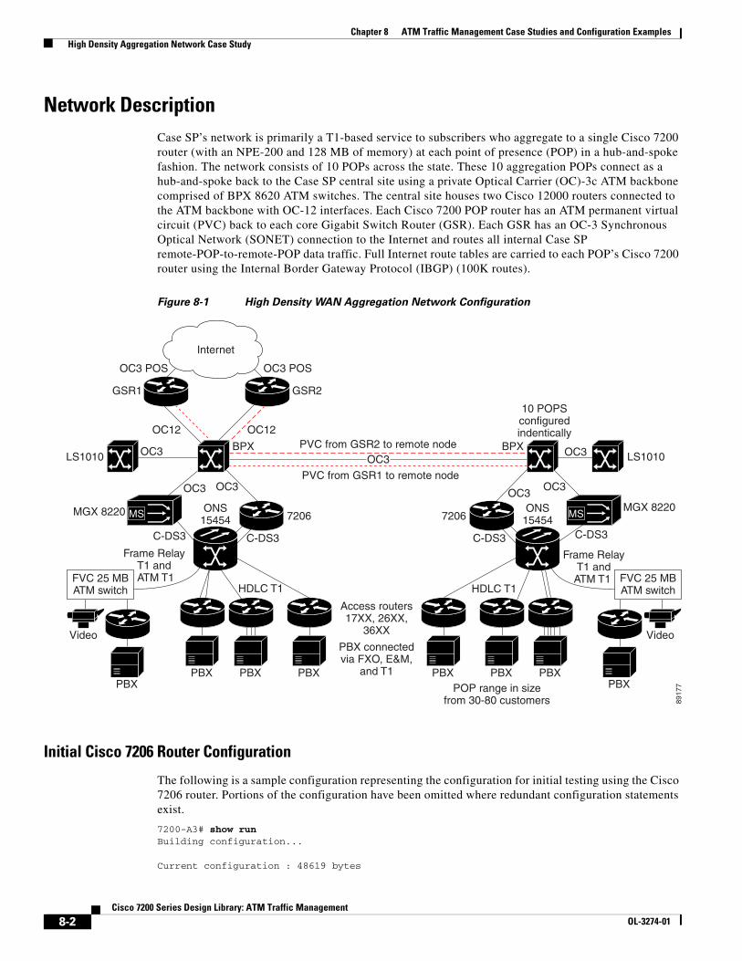
Network DescriptionCase SP’s network is primarily a T1-based service to subscribers who aggregate to a single Cisco 7200 router (with an NPE-200 and 128 MB of memory) at each point of presence (POP) in a hub-and-spoke fashion. The network consists of 10 POPs across the state. These 10 aggregation POPs connect as a hub-and-spoke back to the Case SP central site using a private Optical Carrier (OC)-3c ATM backbone comprised of BPX 8620 ATM switches. The central site houses two Cisco 12000 routers connected to the ATM backbone with OC-12 interfaces. Each Cisco 7200 POP router has an ATM permanent virtual circuit (PVC) back to each core Gigabit Switch Router (GSR). Each GSR has an OC-3 Synchronous Optical Network (SONET) connection to the Internet and routes all internal Case SP remote-POP-to-remote-POP data traffic. Full Internet route tables are carried to each POP’s Cisco 7200 router using the Internal Border Gateway Protocol (IBGP) (100K routes).
Figure 8-1 High Density WAN Aggregation Network Configuration
Initial Cisco 7206 Router Configuration
The following is a sample configuration representing the configuration for initial testing using the Cisco 7206 router. Portions of the configuration have been omitted where redundant configuration statements exist.
7200-A3# show runBuilding configuration...
Current configuration : 48619 bytes
MS
PVC from GSR2 to remote node
Internet
10 POPSconfiguredindentically
POP range in sizefrom 30-80 customers 89
177
OC3 POSOC3 POS
GSR1 GSR2
OC12 OC12
OC3LS1010 LS1010
PVC from GSR1 to remote node
OC3
OC3
7206
Access routers17XX, 26XX,
36XX
PBX connectedvia FXO, E&M,
and T1
BPX BPX
OC3
C-DS3
Frame RelayT1 and ATM T1
PBX
C-DS3
HDLC T1 HDLC T1
ONS15454
ONS15454
MGX 8220
OC3
PBX
Video
PBX PBX
FVC 25 MBATM switch
MS
OC3
7206
OC3
C-DS3
Frame RelayT1 andATM T1
PBX
C-DS3
MGX 8220
PBX
Video
PBXPBX
FVC 25 MBATM switch
8-2Cisco 7200 Series Design Library: ATM Traffic Management
OL-3274-01

Chapter 8 ATM Traffic Management Case Studies and Configuration Examples High Density Aggregation Network Case Study
!version 12.1service timestamps debug uptimeservice timestamps log uptimeno service password-encryptionservice internal!hostname 7200-A3!boot system disk0:c7200-p-mz.121-7.E.bin!ip subnet-zero!no ip fingerno ip domain-lookup!controller T3 5/0 framing m23 t1 1 channel-group 0 timeslots 1-24 t1 2 channel-group 0 timeslots 1-24 t1 3 channel-group 0 timeslots 1-24 t1 4 channel-group 0 timeslots 1-24 t1 5 channel-group 0 timeslots 1-24 t1 6 channel-group 0 timeslots 1-24 t1 7 channel-group 0 timeslots 1-24 t1 8 channel-group 0 timeslots 1-24 t1 9 channel-group 0 timeslots 1-24 t1 10 channel-group 0 timeslots 1-24 t1 11 channel-group 0 timeslots 1-24 t1 12 channel-group 0 timeslots 1-24 t1 13 channel-group 0 timeslots 1-24 t1 14 channel-group 0 timeslots 1-24 t1 15 channel-group 0 timeslots 1-24 t1 16 channel-group 0 timeslots 1-24 t1 17 channel-group 0 timeslots 1-24 t1 18 channel-group 0 timeslots 1-24 t1 19 channel-group 0 timeslots 1-24 t1 20 channel-group 0 timeslots 1-24 t1 21 channel-group 0 timeslots 1-24 t1 22 channel-group 0 timeslots 1-24 t1 23 channel-group 0 timeslots 1-24 t1 24 channel-group 0 timeslots 1-24 t1 25 channel-group 0 timeslots 1-24 t1 26 channel-group 0 timeslots 1-24 t1 27 channel-group 0 timeslots 1-24 t1 28 channel-group 0 timeslots 1-24!! Note: Two Channelized T3 controllers are configured similarly! with 28 channel-groups, for a total of 112 Serial interfaces.!controller T3 5/1 framing m23 t1 1 channel-group 0 timeslots 1-24![text omitted]!interface Loopback0 ip address 10.15.1.1 255.255.255.255!interface FastEthernet1/0 ip address 10.30.1.20 255.255.255.0 no ip mroute-cache duplex full!
8-3Cisco 7200 Series Design Library: ATM Traffic Management
OL-3274-01

Chapter 8 ATM Traffic Management Case Studies and Configuration Examples High Density Aggregation Network Case Study
interface ATM4/0 no ip address load-interval 30 no atm sonet ilmi-keepalive no atm ilmi-keepalive!interface ATM4/0.1 point-to-point ip address 10.10.10.2 255.255.255.0 pvc 40/40 vbr-nrt 155000 155000 1000 encapsulation aal5snap!! Only a partial listing of the configured ! Channelized T3 controllers is shown.! interface Serial5/0/1:0 ip address 10.13.1.1 255.255.255.0 load-interval 30 no keepalive tx-ring-limit 12 fair-queue 32 64 28 hold-queue 30 out!interface Serial5/0/2:0 ip address 10.13.2.1 255.255.255.0 load-interval 30 no keepalive tx-ring-limit 12 fair-queue 32 64 28 hold-queue 30 out!interface Serial5/0/3:0 ip address 10.13.3.1 255.255.255.0 load-interval 30 no keepalive tx-ring-limit 12 fair-queue 32 64 28 hold-queue 30 out!interface Serial5/0/4:0 ip address 10.13.4.1 255.255.255.0 load-interval 30 no keepalive tx-ring-limit 12 fair-queue 32 64 28 hold-queue 30 out![text omitted]!interface Serial5/0/27:0 ip address 10.13.27.1 255.255.255.0 load-interval 30 no keepalive tx-ring-limit 12 fair-queue 32 64 28 hold-queue 30 out!interface Serial5/0/28:0 ip address 10.13.28.1 255.255.255.0 load-interval 30 no keepalive tx-ring-limit 12 fair-queue 32 64 28 hold-queue 30 out
8-4Cisco 7200 Series Design Library: ATM Traffic Management
OL-3274-01

Chapter 8 ATM Traffic Management Case Studies and Configuration Examples High Density Aggregation Network Case Study
!interface Serial5/1/1:0 ip address 10.14.1.1 255.255.255.0 load-interval 30 no keepalive tx-ring-limit 12 fair-queue 32 64 28 hold-queue 30 out!interface Serial5/1/2:0 ip address 10.14.2.1 255.255.255.0 load-interval 30 no keepalive tx-ring-limit 12 fair-queue 32 64 28 hold-queue 30 out![text omitted]!interface Serial5/1/27:0 ip address 10.14.27.1 255.255.255.0 load-interval 30 no keepalive tx-ring-limit 12 fair-queue 32 64 28 hold-queue 30 out!interface Serial5/1/28:0 ip address 10.14.28.1 255.255.255.0 load-interval 30 no keepalive tx-ring-limit 12 fair-queue 32 64 28 hold-queue 30 out!router eigrp 100 network 10.7.3.0 0.0.0.255 network 10.13.0.0 network 10.14.0.0 network 10.15.0.0 network 10.16.0.0 network 10.15.1.1 0.0.0.0 network 10.21.0.0 network 10.200.1.0 no auto-summary no eigrp log-neighbor-changes!router bgp 100 no synchronization bgp log-neighbor-changes neighbor 10.26.1.1 remote-as 100 neighbor 10.26.1.1 update-source Loopback0!! Note: A static route exists for each destination subnet on a Serial interface. ! Only the first four and last four are shown here as an example.!ip classlessip route 10.7.3.0 255.255.255.0 Serial5/0/4:0ip route 10.7.1.0 255.255.255.0 Serial5/0/2:0ip route 10.22.1.0 255.255.255.0 ATM4/0.1ip route 10.40.1.0 255.255.255.0 Serial5/0/1:0![text omitted]!
8-5Cisco 7200 Series Design Library: ATM Traffic Management
OL-3274-01

Chapter 8 ATM Traffic Management Case Studies and Configuration Examples High Density Aggregation Network Case Study
ip route 10.40.111.0 255.255.255.0 Serial6/1/27:0ip route 10.40.112.0 255.255.255.0 Serial6/1/28:0ip route 10.50.0.0 255.0.0.0 Serial5/0/1:0ip route 10.70.0.0 255.255.0.0 10.10.10.1no ip http server!access-list 100 permit udp any any range 1718 1720access-list 100 permit udp any range 1718 1720 anyaccess-list 100 permit tcp any any range 1718 1720access-list 100 permit tcp any range 1718 1720 anyaccess-list 100 permit udp any range 54000 56000 anyaccess-list 100 permit udp any any range 54000 56000access-list 101 permit ip 10.50.5.0 0.0.0.15 host 10.6.6.6access-list 101 permit ip 10.60.6.0 0.0.0.15 host 10.7.7.7access-list 101 permit ip 10.60.6.0 0.0.0.15 host 10.7.7.8access-list 101 permit ip 10.60.6.0 0.0.0.15 host 10.7.7.9access-list 101 permit ip 10.60.6.0 0.0.0.15 host 10.7.7.0access-list 101 permit ip host 10.1.1.1 host 10.7.7.0access-list 101 permit ip host 10.1.1.1 host 10.7.7.6access-list 101 permit ip host 10.1.1.1 host 10.7.6.6access-list 101 permit ip host 10.1.1.1 host 10.3.6.6access-list 101 deny ip host 10.0.0.0 host 10.0.0.0access-list 101 deny ip 10.2.8.0 0.0.0.15 10.0.1.0 10.15.63.255access-list 101 permit ip any anyroute-map local permit 10 match ip address 100 set ip precedence flash-override!!!line con 0 transport input noneline aux 0line vty 0 4 password [text omitted] loginline vty 5 15 login!end
Recommended Cisco 7206VXR Router Configuration
The following is a sample of the recommended configuration for the Cisco 7206VXR router during this testing. Portions of the configuration have been omitted where redundant configuration statements exist.
7200-A3-VXR-RED# show runBuilding configuration...
Current configuration : 48619 bytes!version 12.1service timestamps debug uptimeservice timestamps log uptimeno service password-encryptionservice internal!hostname 7200-A3-VXR-RED!boot system disk0:c7200-p-mz.121-7.E.binboot system disk0:c7200-is-mz.121_7_E.dan.bin!
8-6Cisco 7200 Series Design Library: ATM Traffic Management
OL-3274-01

Chapter 8 ATM Traffic Management Case Studies and Configuration Examples High Density Aggregation Network Case Study
ip subnet-zeroip cef!!no ip fingerno ip domain-lookup!!class-map match-all call-control match access-group 100class-map match-all voice match ip precedence 5class-map match-all default match any !!policy-map llq-atm class voice priority 596 class call-control bandwidth 10policy-map llq-serial-250 class voice priority 250 class call-control bandwidth 10 class default bandwidth 892 random-detect random-detect precedence 0 2 4 5 random-detect precedence 1 2 4 5 random-detect precedence 2 2 4 5 random-detect precedence 3 2 4 5 policy-map llq-serial-548 class voice priority 548 class call-control bandwidth 10 class default bandwidth 500 random-detect random-detect precedence 0 2 4 5 random-detect precedence 1 2 4 5 random-detect precedence 2 2 4 5 random-detect precedence 3 2 4 5 policy-map llq-serial-48 class voice priority 48 class call-control bandwidth 10 class default bandwidth 1000 random-detect random-detect precedence 0 2 4 5 random-detect precedence 1 2 4 5 random-detect precedence 2 2 4 5 random-detect precedence 3 2 4 5 !!controller T3 5/0 framing m23 t1 1 channel-group 0 timeslots 1-24 t1 2 channel-group 0 timeslots 1-24 t1 3 channel-group 0 timeslots 1-24
8-7Cisco 7200 Series Design Library: ATM Traffic Management
OL-3274-01

Chapter 8 ATM Traffic Management Case Studies and Configuration Examples High Density Aggregation Network Case Study
t1 4 channel-group 0 timeslots 1-24 t1 5 channel-group 0 timeslots 1-24 t1 6 channel-group 0 timeslots 1-24 t1 7 channel-group 0 timeslots 1-24 t1 8 channel-group 0 timeslots 1-24 t1 9 channel-group 0 timeslots 1-24 t1 10 channel-group 0 timeslots 1-24 t1 11 channel-group 0 timeslots 1-24 t1 12 channel-group 0 timeslots 1-24 t1 13 channel-group 0 timeslots 1-24 t1 14 channel-group 0 timeslots 1-24 t1 15 channel-group 0 timeslots 1-24 t1 16 channel-group 0 timeslots 1-24 t1 17 channel-group 0 timeslots 1-24 t1 18 channel-group 0 timeslots 1-24 t1 19 channel-group 0 timeslots 1-24 t1 20 channel-group 0 timeslots 1-24 t1 21 channel-group 0 timeslots 1-24 t1 22 channel-group 0 timeslots 1-24 t1 23 channel-group 0 timeslots 1-24 t1 24 channel-group 0 timeslots 1-24 t1 25 channel-group 0 timeslots 1-24 t1 26 channel-group 0 timeslots 1-24 t1 27 channel-group 0 timeslots 1-24 t1 28 channel-group 0 timeslots 1-24!! Note: Each of four Channelized T3 controllers is configured similarly! with 28 channel-groups, for a total of 112 Serial interfaces.!controller T3 5/1 framing m23 t1 1 channel-group 0 timeslots 1-24![text omitted]!controller T3 6/0 framing m23 t1 1 channel-group 0 timeslots 1-24![text omitted]!controller T3 6/1 framing m23 t1 1 channel-group 0 timeslots 1-24![text omitted]!interface Loopback0 ip address 10.15.1.1 255.255.255.255!interface FastEthernet1/0 ip address 10.30.1.20 255.255.255.0 no ip mroute-cache duplex full!interface ATM4/0 no ip address load-interval 30 no atm sonet ilmi-keepalive no atm ilmi-keepalive!interface ATM4/0.1 point-to-point ip address 10.10.10.2 255.255.255.0 pvc 40/40
8-8Cisco 7200 Series Design Library: ATM Traffic Management
OL-3274-01

Chapter 8 ATM Traffic Management Case Studies and Configuration Examples High Density Aggregation Network Case Study
vbr-nrt 155000 155000 1000 encapsulation aal5snap service-policy output llq-atm !! Only a partial listing of the configured ! Channelized T3 controllers is shown.! interface Serial5/0/1:0 ip address 10.13.1.1 255.255.255.0 load-interval 30 no keepalive tx-ring-limit 12 service-policy output llq-serial-250!interface Serial5/0/2:0 ip address 10.13.2.1 255.255.255.0 load-interval 30 no keepalive tx-ring-limit 12 service-policy output llq-serial-250!interface Serial5/0/3:0 ip address 10.13.3.1 255.255.255.0 load-interval 30 no keepalive tx-ring-limit 12 service-policy output llq-serial-48!interface Serial5/0/4:0 ip address 10.13.4.1 255.255.255.0 load-interval 30 no keepalive tx-ring-limit 12 service-policy output llq-serial-548![text omitted]!interface Serial5/0/27:0 ip address 10.13.27.1 255.255.255.0 load-interval 30 no keepalive tx-ring-limit 12 fair-queue 32 64 28 hold-queue 30 out!interface Serial5/0/28:0 ip address 10.13.28.1 255.255.255.0 load-interval 30 no keepalive tx-ring-limit 12 fair-queue 32 64 28 hold-queue 30 out!interface Serial5/1/1:0 ip address 10.14.1.1 255.255.255.0 load-interval 30 no keepalive tx-ring-limit 12 fair-queue 32 64 28 hold-queue 30 out!interface Serial5/1/2:0 ip address 10.14.2.1 255.255.255.0 load-interval 30
8-9Cisco 7200 Series Design Library: ATM Traffic Management
OL-3274-01

Chapter 8 ATM Traffic Management Case Studies and Configuration Examples High Density Aggregation Network Case Study
no keepalive tx-ring-limit 12 fair-queue 32 64 28 hold-queue 30 out...interface Serial5/1/27:0 ip address 10.14.27.1 255.255.255.0 load-interval 30 no keepalive tx-ring-limit 12 fair-queue 32 64 28 hold-queue 30 out!interface Serial5/1/28:0 ip address 10.14.28.1 255.255.255.0 load-interval 30 no keepalive tx-ring-limit 12 fair-queue 32 64 28 hold-queue 30 out!interface Serial6/0/1:0 ip address 10.15.1.1 255.255.255.0 load-interval 30 no keepalive tx-ring-limit 12 fair-queue 32 64 28 hold-queue 30 out!interface Serial6/0/2:0 ip address 10.15.2.1 255.255.255.0 load-interval 30 no keepalive tx-ring-limit 12 fair-queue 32 64 28 hold-queue 30 out![text omitted]!interface Serial6/0/27:0 ip address 10.15.27.1 255.255.255.0 load-interval 30 no keepalive tx-ring-limit 12 fair-queue 32 64 28 hold-queue 30 out!interface Serial6/0/28:0 ip address 10.15.28.1 255.255.255.0 load-interval 30 no keepalive tx-ring-limit 12 fair-queue 32 64 28 hold-queue 30 out!interface Serial6/1/1:0 ip address 10.16.1.1 255.255.255.0 load-interval 30 no keepalive tx-ring-limit 12 fair-queue 32 64 28 hold-queue 30 out
8-10Cisco 7200 Series Design Library: ATM Traffic Management
OL-3274-01

Chapter 8 ATM Traffic Management Case Studies and Configuration Examples High Density Aggregation Network Case Study
!interface Serial6/1/2:0 ip address 10.16.2.1 255.255.255.0 load-interval 30 no keepalive tx-ring-limit 12 fair-queue 32 64 28 hold-queue 30 out![text omitted]!interface Serial6/1/27:0 ip address 10.16.27.1 255.255.255.0 load-interval 30 no keepalive tx-ring-limit 12 fair-queue 32 64 28 hold-queue 30 out!interface Serial6/1/28:0 ip address 10.16.28.1 255.255.255.0 load-interval 30 no keepalive tx-ring-limit 12 fair-queue 32 64 28 hold-queue 30 out!router eigrp 100 network 10.7.3.0 0.0.0.255 network 10.13.0.0 network 10.14.0.0 network 10.15.0.0 network 10.16.0.0 network 10.15.1.1 0.0.0.0 network 10.21.0.0 network 10.200.1.0 no auto-summary no eigrp log-neighbor-changes!router bgp 100 no synchronization bgp log-neighbor-changes neighbor 10.26.1.1 remote-as 100 neighbor 10.26.1.1 update-source Loopback0!! Note: A static route exists for each destination subnet on a Serial interface. ! Only the first four and last four are shown here as an example.!ip classlessip route 10.7.3.0 255.255.255.0 Serial5/0/4:0ip route 10.7.1.0 255.255.255.0 Serial5/0/2:0ip route 10.22.1.0 255.255.255.0 ATM4/0.1ip route 10.40.1.0 255.255.255.0 Serial5/0/1:0![text omitted]!ip route 10.40.111.0 255.255.255.0 Serial6/1/27:0ip route 10.40.112.0 255.255.255.0 Serial6/1/28:0ip route 10.50.0.0 255.0.0.0 Serial5/0/1:0ip route 10.70.0.0 255.255.0.0 10.10.10.1no ip http server!access-list 100 permit udp any any range 1718 1720access-list 100 permit udp any range 1718 1720 any
8-11Cisco 7200 Series Design Library: ATM Traffic Management
OL-3274-01

Chapter 8 ATM Traffic Management Case Studies and Configuration Examples High Density Aggregation Network Case Study
access-list 100 permit tcp any any range 1718 1720access-list 100 permit tcp any range 1718 1720 anyaccess-list 100 permit udp any range 54000 56000 anyaccess-list 100 permit udp any any range 54000 56000access-list 101 permit ip 10.50.5.0 0.0.0.15 host 10.6.6.6access-list 101 permit ip 10.60.6.0 0.0.0.15 host 10.7.7.7access-list 101 permit ip 10.60.6.0 0.0.0.15 host 10.7.7.8access-list 101 permit ip 10.60.6.0 0.0.0.15 host 10.7.7.9access-list 101 permit ip 10.60.6.0 0.0.0.15 host 10.7.7.0access-list 101 permit ip host 10.1.1.1 host 10.7.7.0access-list 101 permit ip host 10.1.1.1 host 10.7.7.6access-list 101 permit ip host 10.1.1.1 host 10.7.6.6access-list 101 permit ip host 10.1.1.1 host 10.3.6.6access-list 101 deny ip host 10.0.0.0 host 10.0.0.0access-list 101 deny ip 10.2.8.0 0.0.0.15 10.0.1.0 10.15.63.255access-list 101 permit ip any anyroute-map local permit 10 match ip address 100 set ip precedence flash-override!!!line con 0 transport input noneline aux 0line vty 0 4 password [text omitted] loginline vty 5 15 login!end
Network History and Problem StatementThe network was originally designed to carry data traffic. Since that time, it has grown significantly in terms of both the number of remote T1s at each aggregation POP, as well as the amount of data being transferred to and from each remote location. Many of the T1 or multiple T1 customers are schools with hundreds to thousands of users generating thousands of flows. The number of flows at a given site that are requesting data from the Internet has resulted in some subscriber links being constantly oversubscribed. The outbound T1 oversubscription has triggered ingress buffer starvation for the high-speed interface (which is the ATM Port Adapter PA-A3 OC-3) on the Cisco 7200 routers. This problem is seen in the form of ignores, flushes, and cyclic redundancy checks (CRCs) on the ATM interface. This change in network conditions has resulted in poor performance for customers even on lightly loaded links.
The constantly oversubscribed customers were aware of and accepted their performance issues, but the other subscribers were unhappy with the poor performance of their more lightly loaded links. Due to budget pressure, these oversubscribed accounts would not buy enough bandwidth to solve their oversubscription problem. Also, due to competitive pressure from other service providers, Case SP could not force them to do so.
In addition to facing performance problems on the data side, Case SP was also offering a trial for a Voice over Internet Protocol (VoIP) service to some customers. They wanted to be able to roll it out to more customers, plus add video over IP. Case SP’s current video offering was in the form of H.320 and they were evaluating adding H.323 video on the network. It appeared that the platform was already becoming undersized for the applications it was supporting at that time, so it was highly unlikely that it would be
8-12Cisco 7200 Series Design Library: ATM Traffic Management
OL-3274-01

Chapter 8 ATM Traffic Management Case Studies and Configuration Examples High Density Aggregation Network Case Study
able to scale to the next level. Thus, the challenge was not only to find a solution to the existing performance issues but also to enable the network to support multiple differentiated services, such as VoIP and IP-based video conferencing.
Case ObjectivesThe following test objectives were established for this case study:
• Validate lab test criteria by reproducing ignored errors seen in the live environment during oversubscription of egress links.
• Identify the performance thresholds of the current platform in order to determine which POPs are affected and why.
• Test various methods for controlling the oversubscription problem.
• Identify a short-term solution to the existing platform that will stabilize the network, support the current rate of growth, and allow for added services such as voice and video conferencing.
• Test the performance of multiservice applications under congested network conditions in order to validate quality of service (QoS).
• Test a longer-term, next-generation solution to determine if a different platform is needed to provide significant scalability options.
Overview of the TestingThe Devices Under Test (DUT) included the Cisco 7200 router with an NPE-200, Cisco 7200VXR with an NPE-400, and the Cisco 7600 router.
After replicating the current customer environment, the Cisco lab team team was able to successfully reproduce the problem. In the test environment, the Cisco 7200 routers had a high-speed interface that consistently received an oversubscription of data destined for only a few of the lower-speed T1 interfaces. The ATM interface was far from being oversubscribed; it was the egress T1s that were driven beyond port speeds. This caused buffer starvation to occur, thus impacting even the non-oversubscribed links on the same router.
Each interface on the Cisco 7200 series router has a private interface pool in which all received packets over that interface are stored. The packet contents remain in the pool of the ingress interface until they are transmitted. While the packets are awaiting transmission out the low-speed (T1) interfaces (which were oversubscribed), the buffers cannot be used for incoming traffic. This caused the ATM interface to experience a lot of ignores in the oversubscribed environment. Ignores indicate that the data made it to the router, but was dropped prior to any processing or queueing. This occurred because there were not enough buffers to receive data from the ATM interface and process it through the router to the egress interface. Thus, with even just a few oversubscribed T1s, all connections were affected, as ingress data was dropped indiscriminately.
Testing Methodology
Two types of tests were run against the different router platforms being tested:
• The first test on the router provided a full load of data for each egress T1 in order to provide a maximum load reference. Traffic was generated in both directions for all T1s (1.536 Mbps per T1, TCP frames at 1024 bytes).
8-13Cisco 7200 Series Design Library: ATM Traffic Management
OL-3274-01

Chapter 8 ATM Traffic Management Case Studies and Configuration Examples High Density Aggregation Network Case Study
• The second test used a customer-supplied breakdown of the typical protocol and packet size distribution seen in the network, as well as a common interface load distribution in which only a percentage of the links were oversubscribed. This information was used to provide a customer mix load result. Table 8-1 shows the percentage of different types of traffic typically found on the network and the typical frame sizes and priorities.
Both tests were subjected to an injection of 120,000 BGP routes with 5,000 periodic flaps and 500 Enhanced Interior Gateway Protocol (EIGRP) routes with 60 periodic flaps. This route table load was used to simulate the customer’s current environment with 20 percent growth. Table 8-2 shows the load that was used to test the T1s.
Testing of Existing Cisco 7200 Series Router
The first set of tests were conducted using the existing Cisco 7200 series router with an NPE-200 and 128 MB DRAM.
The first set of tests were conducted to reproduce Case SP’s oversubscription problem, identify the performance threshholds of the current platform, and test different ways of controlling the oversubscription problem using the current platform.
With a test bed set up for 56 T1s, four different approaches were tested in an attempt to overcome the issue of buffer starvation. Of the four optimizations attempted, configuring an output rate limit on the serial interfaces worked.
However, the following three approaches were also tried:
• Modifying the TX ring limit on the serial interface
• Implementing Weighted Fair Queueing (WFQ) on the serial interface
Table 8-1 Case SP Traffic Mix
Traffic TypeFrame Size (bytes)
% Total Network Bandwidth Priority Type of Service (TOS)
Hypertext Transfer Protocol (HTTP)
256 57 4 2
Transmission Control Protocol (TCP)
1000 29 3 3
User Datagram Protocol (UDP)
80 5 1 5
File Transfer Protocol (FTP)
1500 9 2 4
Table 8-2 Case SP Traffic Load
T1 Traffic Loads Load per T1 (Mbps) Example Load Using 56 T1s
25% 1.536 14 T1s will have a load of 1.53 Mbps
40% 1.200 22 T1s will have a load of 1.2 Mbps
25% 0.500 12 T1s will have a load of 500 Kbps
15% 0.100 8 T1s will have a load of 100 Kbps
8-14Cisco 7200 Series Design Library: ATM Traffic Management
OL-3274-01

Chapter 8 ATM Traffic Management Case Studies and Configuration Examples High Density Aggregation Network Case Study
• Implementing Weighted Random Early Detect (WRED)
These three approaches did not fully address the problem, and are described further in the “Results of Existing 7200 Platform Testing Phase” section.
Results of Existing 7200 Platform Testing Phase
This section describes the configurations attempted and the results of the four approaches.
Modifying the TX Ring Limit
In this approach, there was an attempt to limit the number of buffers an interface can hold using the tx-ring-limit command. Although this approach yielded modest improvement, it did not drastically improve the discards.
The following is an example of the configuration:
interface Serial5/0/3:0ip address 10.13.3.1 255.255.255.0tx-ring-limit 12
Implementing WFQ
In this approach, queueing limits were configured on the serial interface. Configuring fair queueing with buffer limits helped reduce ATM ignores under light congestion, but it did not correct the problem under severe congestion.
The following is an example of the configuration:
interface Serial5/0/1:0ip address 10.13.1.1 255.255.255.0fair-queue 32 64 28hold-queue 30 out
Implementing WRED
WRED requires enabling of Cisco Express Forwarding (CEF). IP CEF could not be used in this scenario due to the size of the route tables, as well as limited CPU and memory resources available on NPE-200.
Configuring an Output Rate Limit
In this approach, output rate limits were configured on the serial interfaces. Rate limiting resolved the issue of buffer starvation at the ingress interface. Packets were dropped at the offending output interface and non-oversubscribed ports performed normally. This was the result that Case SP desired. Be aware, however, that the use of rate limiting increases Central Processing Unit (CPU) utilization (by around 20 percent for the 14 T1s tested in this scenario). This approach also has the potential to cause the Transmission Control Protocol (TCP) window to shut, thereby reducing application throughput for those links.
The following is an example of the configuration:
interface Serial5/0/3:0ip address 10.13.3.1 255.255.255.0rate-limit output 1536000 1500 2000 conform-actiontransmit exceed-action drop
Note The Committed Access Rate (CAR) feature is considered a legacy form of policing and is no longer recommended for use on the Cisco 7200 series routers. Newer, class-based policing mechanisms are now available using the modular QoS CLI (MQC) configuration method.
8-15Cisco 7200 Series Design Library: ATM Traffic Management
OL-3274-01

Chapter 8 ATM Traffic Management Case Studies and Configuration Examples High Density Aggregation Network Case Study
Conclusions of Existing 7200 Platform Testing Phase
With the current Cisco 7200 platform and using the full T1 load setup, a 100 percent load was determined to be 28 T1s. Using the customer traffic mix, the maximum load was 56 T1s. The NPE-200 could not intelligently discard traffic under heavy load conditions due to the lack of congestion avoidance techniques like WRED (which could not be turned on because it requires CEF, and CEF could not be enabled due to the high CPU usage for other services placed on the router).
Testing of Upgraded Cisco 7200 VXR Platform with NPE-400
In the second phase of testing, the router platform was upgraded to the NPE-400, with a faster processor. The goal of this testing was to identify a short-term solution that would stabilize the network, allow reuse of current router port adapters, and support the addition of VoIP and video services. The same testing methodology was used, but this time IP CEF was enabled on the router. In addition, rate limiting was not configured on the T1 serial interfaces to control discards, but WRED was configured.
Results of Upgraded 7200 Platform Testing Phase
Without using rate limiting, upgrading to the next processor improved control and scalability. The maximum full traffic load was 56 T1s. However, the problem recurred with ignores being received on the ATM PA-A3. To address this, IP CEF was enabled and WRED was used as a mechanism to control discards on the serial interface. Class-based queueing was also used to guarantee varying quality of service levels for different applications.
Implementing WRED
The Cisco WRED protocol combines IP Precedence and RED and provides differentiated drop thresholds for premium (high priority) traffic versus standard (lower priority) traffic. This allows Case SP to drop packets from the standard customer before dropping packets (if at all) from the premium customer or traffic type.
The following is an example of the WRED policy map configuration for the serial interface:
class-map match-all call-control match access-group 100class-map match-all voice match ip precedence 5class-map match-all default match any!policy-map llq-atm class voice priority 596 class call-control bandwidth 10!policy-map llq-serial-250 class voice priority 250 class call-control bandwidth 10 class default bandwidth 892 random-detect random-detect precedence 0 2 4 5 random-detect precedence 1 2 4 5 random-detect precedence 2 2 4 5 random-detect precedence 3 2 4 5!
8-16Cisco 7200 Series Design Library: ATM Traffic Management
OL-3274-01

Chapter 8 ATM Traffic Management Case Studies and Configuration Examples High Density Aggregation Network Case Study
policy-map llq-serial-48 class voice priority 48 class call-control bandwidth 10 class default bandwidth 1000 random-detect random-detect precedence 0 2 4 5 random-detect precedence 1 2 4 5 random-detect precedence 2 2 4 5 random-detect precedence 3 2 4 5
Configuring WRED with the above parameters allowed the oversubscribed interfaces to intelligently discard data without affecting the non-oversubscribed users. WRED did not have any detrimental effect on CPU utilization (in fact, there was only an increase of about 3 percent).
The configuration implements the random-detect precedence command using the following syntax:
random-detect precedence precedence min-threshold max-threshold mark-prob-denominator
The packet drop probability is based on the minimum threshold, maximum threshold, and mark probability denominator. When the average queue depth is above the minimum threshold of packets, RED starts dropping packets. The rate of packet drops increases linearly as the average queue size increases, until the average queue size reaches the maximum threshold.
The mark probability denominator is the fraction of packets dropped when the average queue depth is at the maximum threshold. As configured above, if the denominator is 5, one out of every five packets is dropped when the average queue is at the maximum threshold. When the average queue size is above the maximum threshold, all packets are dropped.
WRED Restrictions
At the time of this case study, WRED was characterized by the following restrictions:
• When WRED affects protocols other than TCP/IP, the packet sources might resend dropped packets at the same rate and therefore congestion is not decreased. WRED works best when most of the traffic is TCP/IP traffic. With TCP, dropped packets indicate congestion, so the packet source reduces its transmission rate.
• WRED treats non-IP traffic as precedence 0, the lowest precedence. Therefore, non-IP traffic is dropped more often than IP traffic.
• WRED does not support ATM encapsulations using AAL5-MUX.
• WRED requires CEF switching.
Conclusions of Upgraded 7200 Platform Testing Phase
With the upgraded platform and all the necessary tools available on the Cisco 7200 VXR, WRED was found to be the best way to control discards on a percentage of T1 serial links. The increase in CPU utilization from baseline records proved to be minimal (3 percent increase).
Additional tests were conducted with 56 T1s and 104 T1s and WRED rate limiting.
In the 56 T1 tests, 14 T1s were each overdriven at 2.0 Mbps/T1 while the remaining 42 T1s were loaded to their specific traffic rates. When the WRED rate limit was set at 1.475 Mbps per T1, no ATM ignores or errors occurred.
8-17Cisco 7200 Series Design Library: ATM Traffic Management
OL-3274-01

Chapter 8 ATM Traffic Management Case Studies and Configuration Examples High Density Aggregation Network Case Study
When generating traffic to 104 T1s (based on the customer’s traffic load mix, with none over line rate), the processor was at an acceptable utilization percentage. No errors occurred (no ATM ignores, CRCs, flushes, or input errors), serial interfaces were left at default configurations, and fair queueing (with no prioritization or rate limiting) was configured.
When overdriving 20 T1s to 2.0 Mpbs/T1, with the other 84 T1s running at their normal rates with the same protocol mix and no rate control, ATM ignores did occur. CPU utilization increased by approximately 8 percent. When overdriving 20 T1s to 2.0 Mpbs/T1, with the other 84 T1s running at their normal rates with the same protocol mix but with WRED as the rate control mechanism, ATM ignores did not occur. This proved the capability of the upgraded, short-term solution for this customer scenario.
Multiservice Tests on the Cisco 7200 VXR Platform with NPE-400
Once the platform was configured to control the oversubscription issues, multiservice capabilities were tested. With 70 T1s being oversubscribed at 1.7 Mbps, WRED alleviated the buffer starvation problem that was previously seen as ignores on the ingress ATM OC-3 port adapter. WRED was applied to the default class of traffic (anything with a precedence of less than 3), and the buffers were tuned to reduce the queue size on the serial ports in order to prevent buffer starvation.
Buffer starvation was alleviated by applying WRED on the default policy, as shown in the following configuration example:
policy-map llq-serial-250 class voice priority 250 class call-control bandwidth 10 class default bandwidth 892 random-detect random-detect precedence 0 2 4 5 random-detect precedence 1 2 4 5 random-detect precedence 2 2 4 5 random-detect precedence 3 2 4 5
Note When creating policies, be sure to consider that match criteria is applied on the first match of classes. Therefore, the default class (if it is the least important traffic classification) should be the last class that you configure.
By applying Low Latency Queueing (LLQ) for voice and Class-Based Weighted Fair Queueing (CBWFQ) for voice signaling, voice quality was consistently good, even in heavily congested links.
Use of H.323 gatekeeper allowed for centralized management of the dialing plan. No issues with call-setup delay were experienced. Channel Associated Signaling (CAS) was used between the private branch exchange (PBX) and the Cisco 2600 and Cisco 3600 routers. CAS typically can add call-setup delays of up to 3 to 5 seconds.
Testing of Cisco 7600 FlexWAN as Long-Term Solution
The Cisco 7600 configuration included a Supervisor II, with Multilayer Switch Feature Card 2 (MSFC2), 48-port 10/100 Ethernet card, and two FlexWAN modules containing two Multichannel Port Adapter (PA-MC)-T3+ and a PA-A3-OC3. The 48-port RJ-45 card was used to connect a router for injecting EIGRP routes and the gatekeeper for the local zone. The connectivity to the Cisco 7600 was achieved using an OC-3 link. The MSFC2 used Cisco IOS Release 12.1(7)E.
8-18Cisco 7200 Series Design Library: ATM Traffic Management
OL-3274-01

Chapter 8 ATM Traffic Management Case Studies and Configuration Examples QoS Testing for ATM in Airport Case Study
A total of 11 tests were performed with 120,000 BGP routes (5,000 routes flapping every 90 seconds) and 500 EIGRP routes (60 routes flapping every 90 seconds).
In this testing, the 7600 with FlexWAN was the DUT, and the same topology and traffic loads from the previous testing were used. Queueing parameters were set to match the previously tested configuration to provide quality of service.
The customer’s typical traffic mix was used with all 70 T1s being oversubscribed at 1.7 Mbps. Border Gateway Protocol (BGP) and EIGRP routes were injected with 5,000 BGP flaps and 60 EIGRP flaps.
Because of SONET and ATM and ATM Adaption Layer Type-5 (AAL5) overhead, 123 Mbps is the maximum bandwidth that a single OC-3 link can sustain. Traffic was generated in both directions. Due to these overheads, the maximum number of T1s that could be tested was 80.
Multiservice Voice Test
By applying LLQ for voice and CBWFQ for voice signaling, voice quality was good even in heavily congested links. Digital PBX handsets and analog phone sets were tested by the customer for voice quality, delay in call setup, latency, echo, and distortion. A VoIP tester was used to quantitatively test voice. The VoIP tester uses prerecorded voice samples specified in the International Telecommunication Union (ITU) P861 specification. The tester analyzes the resultant voice waveforms and produces a Perceptual Speech Quality Measurement (PSQM) score for the resultant speech waveform. The VoIP tester was used to test PSQM speech quality, latency, and jitter. All tests produced very good voice quality.
QoS Testing for ATM in Airport Case StudyThis case study provides information about QoS strategies to achieve priority for higher precedence data during times of network congestion using the Cisco 7200 series routers in an ATM network servicing voice, video, and data traffic. The customer represented by this case study is an airline. Throughout this case, the customer will be referred to as Case Airline.
This case includes the following sections:
• Network Description, page 8-20
• Case Objectives, page 8-28
• Overview of the Testing, page 8-28
• Case Conclusions, page 8-37
8-19Cisco 7200 Series Design Library: ATM Traffic Management
OL-3274-01

Chapter 8 ATM Traffic Management Case Studies and Configuration Examples QoS Testing for ATM in Airport Case Study
Network DescriptionThe test network was designed to closely emulate the two major classes of airports in the Case Airline network with both airports connected through a Cisco WAN switch carrier cloud back to the simulated City HQ core site as shown in Figure 8-2 on page 8-20. The data flow was to and from LANE LAN segments in City HQ and the remote airport sites.
The Cisco 7206 routers were running Cisco IOS release 12.1(3.4) using the PA-A3 OC-3 ATM port adapters.
Figure 8-2 Physical Network Diagram of Test Network Representing Case Airline
OC
-3O
C-3
OC
-3
Si
City HQ
SimulatedATM carrier
WAN
IP TVserver
IPphones
IP CallManager
TrafficgeneratorTrafficgenerator
OC
-3O
C-3
OC
-3
Si
.1.2
OC-12
Airport 1LS1010
IP TV
72067206
6506
8917
9Trafficgenerator
Trafficgenerator
OC-3
Si
.1.2
OC-12
Airport 2LS1010
IP TV
72067206
6506
OC-3 OC-3
Trafficgenerator
Trafficgenerator
OC-3
OC-12
7206 7206
GE
6506
GE
GE
OC-12 OC-12
LS1010 LS1010LS1010 LS1010
8-20Cisco 7200 Series Design Library: ATM Traffic Management
OL-3274-01

Chapter 8 ATM Traffic Management Case Studies and Configuration Examples QoS Testing for ATM in Airport Case Study
Figure 8-3 shows the logical view of the test network used to represent the Case Airline network.
Figure 8-3 Logical Network Diagram of Test Network Representing Case Airline
Si
.100.101
.102
.2.2
Trafficgenerator.201
TCPserver
Router 4
Si.100.101
.102.1
.2
.2
Trafficgenerator
City HQ
.100
.101
.1 .1 .1
.2 .3
.2.1
.103.103
.101.100
.201
Router 1IP TV
IP TV IP TV
Router 2
HSRP.1
.201
TCPserver
TCPserver IP TV
server
Router 3
AP
101
10.1
01.1
00.X
Airport 1 - 6M
Si
Airport 2 - T1
6M P
VC
10.101.1.X100/100
10.20.2.X 3/0.1
.310.20.1.X 3/0.2
6M P
VC 10.
101.
2.X
2/0.
5
200/
200
4/0.
1
T1 P
VC
10.100.1.X120/120
T1 PVC 10.100.2.X
4/0.2
110/1103/0.3
3/0.1 User1
3/0.2 CoreIP
3/0.4
8917
8
4/0.12/0.4
HSRP.1
IP TVserverIP TVserver
Trafficgenerator
Trafficgenerator
.1
AP
100
10.1
00.1
00.X
4/0.24/0.2
8-21Cisco 7200 Series Design Library: ATM Traffic Management
OL-3274-01

Chapter 8 ATM Traffic Management Case Studies and Configuration Examples QoS Testing for ATM in Airport Case Study
Baseline Cisco 7206 Router Configurations Using FIFO
The following configurations on Cisco 7206 routers represent those used during initial testing of voice, video, and data traffic under congestion with only FIFO queueing in place.
Router 1 ConfigurationCurrent configuration:!version 12.1service timestamps debug datetime msec localtimeservice timestamps log datetime msec localtimeservice password-encryptionservice udp-small-serversservice tcp-small-servers!hostname router1!!!ip subnet-zerono ip domain-lookupip host router4 10.100.100.1ip host router1 10.20.1.2ip host router3 10.101.100.1ip host router2 10.20.1.3!ip multicast-routingip cefcns event-service server!!!!!vc-class atm 6Mbs vbr-nrt 5950 5900 32 oam-pvc manage 3 oam retry 5 3 3 encapsulation aal5snap!interface Loopback0 ip address 10.20.254.2 255.255.255.0 ip pim sparse-dense-mode!interface ATM3/0 no ip address no ip mroute-cache atm pvc 1 0 5 qsaal atm pvc 2 0 16 ilmi no atm ilmi-keepalive!interface ATM3/0.1 multipoint description User ELAN simulating Case Airline user ELAN ip address 10.20.1.2 255.255.255.0 no ip redirects ip pim sparse-dense-mode no ip mroute-cache lane client ethernet elan1 standby 2 timers 1 5 standby 2 priority 110 preempt delay 60 standby 2 ip 10.20.1.1!
8-22Cisco 7200 Series Design Library: ATM Traffic Management
OL-3274-01

Chapter 8 ATM Traffic Management Case Studies and Configuration Examples QoS Testing for ATM in Airport Case Study
interface ATM3/0.2 multipoint description Server ELAN simulating Case Airline COPRIP ip address 10.20.2.2 255.255.255.0 ip helper-address 10.20.1.110 ip helper-address 10.20.1.101 no ip redirects ip pim sparse-dense-mode no ip mroute-cache lane client ethernet elan2 standby 1 timers 1 5 standby 1 priority 100 preempt delay 60 standby 1 ip 10.20.2.1!interface ATM4/0 no ip address no atm ilmi-keepalive!interface ATM4/0.1 point-to-point bandwidth 6000 ip address 10.101.1.1 255.255.255.0 ip pim sparse-dense-mode pvc 100/100 class-vc 6Mbs !!interface ATM4/0.2 point-to-point bandwidth 1000 ip address 10.100.2.1 255.255.255.0 ip pim sparse-dense-mode pvc 110/110 !!router ospf 1 log-adjacency-changes area 100 stub no-summary area 100 range 10.100.0.0 255.255.0.0 area 101 stub no-summary area 101 range 10.101.0.0 255.255.0.0 network 10.20.0.0 0.0.255.255 area 0 network 10.100.0.0 0.0.255.255 area 100 network 10.101.0.0 0.0.255.255 area 101!ip default-gateway 172.26.64.1ip classlessip route 172.26.0.0 255.255.0.0 FastEthernet0/0ip route 172.26.11.0 255.255.255.0 ATM3/0.1ip http serverip pim send-rp-announce Loopback0 scope 16ip pim send-rp-discovery Loopback0 scope 5!![text omitted]!end
Router 2 Configurationversion 12.1service timestamps debug datetime msec localtimeservice timestamps log datetime msec localtimeservice password-encryptionservice udp-small-serversservice tcp-small-servers!
8-23Cisco 7200 Series Design Library: ATM Traffic Management
OL-3274-01

Chapter 8 ATM Traffic Management Case Studies and Configuration Examples QoS Testing for ATM in Airport Case Study
hostname router2!ip subnet-zerono ip domain-lookupip host router1 10.20.1.2ip host router4 10.100.100.1ip host router3 10.101.100.1ip host router2 10.20.1.3!ip multicast-routingip cefcns event-service server!vc-class atm 6Mbs vbr-nrt 5950 5900 32 oam-pvc manage 3 oam retry 5 3 3 encapsulation aal5snap
interface Loopback0 ip address 10.20.254.100 255.255.255.255 ip pim sparse-dense-mode!interface ATM3/0 no ip address atm pvc 1 0 5 qsaal atm pvc 2 0 16 ilmi no atm ilmi-keepalive!interface ATM3/0.1 multipoint description Client ELAN simulating Case Airline User ELAN ip address 10.20.1.3 255.255.255.0 no ip redirects ip pim sparse-dense-mode lane client ethernet elan1 standby 2 timers 1 5 standby 2 priority 150 preempt delay 60 standby 2 ip 10.20.1.1!interface ATM3/0.2 multipoint description server ELAN simulating Case Airline CORIP ip address 10.20.2.3 255.255.255.0 ip helper-address 10.20.1.101 no ip redirects ip pim sparse-dense-mode lane client ethernet elan2 standby 1 timers 1 5 standby 1 priority 110 preempt delay 60 standby 1 ip 10.20.2.1!interface ATM4/0 no ip address load-interval 30 no atm ilmi-keepalive!interface ATM4/0.1 point-to-point bandwidth 6000 ip address 10.101.2.1 255.255.255.0 ip pim sparse-dense-mode pvc 200/200 class-vc 6Mbs !!interface ATM4/0.2 point-to-point
8-24Cisco 7200 Series Design Library: ATM Traffic Management
OL-3274-01

Chapter 8 ATM Traffic Management Case Studies and Configuration Examples QoS Testing for ATM in Airport Case Study
bandwidth 1000 ip address 10.100.1.1 255.255.255.0 ip pim sparse-dense-mode pvc 120/120 !!router ospf 1 log-adjacency-changes area 100 stub no-summary area 100 range 10.100.0.0 255.255.0.0 area 101 stub no-summary area 101 range 10.101.0.0 255.255.0.0 redistribute static subnets network 10.20.0.0 0.0.255.255 area 0 network 10.100.0.0 0.0.255.255 area 100 network 10.101.0.0 0.0.255.255 area 101!ip default-gateway 172.26.64.1ip classlessip route 172.26.11.0 255.255.255.0 10.20.1.4ip http serverip pim send-rp-announce Loopback0 scope 16ip pim send-rp-discovery Loopback0 scope 5!!![text omitted]!end
Router 3 Configurationversion 12.1service timestamps debug datetime msec localtimeservice timestamps log datetime msec localtimeservice password-encryptionservice udp-small-serversservice tcp-small-servers!hostname router3!!clock calendar-validip subnet-zerono ip domain-lookupip host router4 10.100.100.1ip host router1 10.20.1.2ip host router3 10.101.100.1ip host router2 10.20.1.3!ip multicast-routingip cefcns event-service server!!!!!vc-class atm 6Mbs vbr-nrt 5950 5900 32 oam-pvc manage 3 oam retry 5 3 3 encapsulation aal5snap!
8-25Cisco 7200 Series Design Library: ATM Traffic Management
OL-3274-01

Chapter 8 ATM Traffic Management Case Studies and Configuration Examples QoS Testing for ATM in Airport Case Study
interface Loopback0 description "Router2 - Loopback address and Router ID" ip address 10.101.254.1 255.255.255.255 ip pim sparse-dense-mode!interface ATM2/0 no ip address no ip mroute-cache load-interval 30 atm pvc 1 0 5 qsaal atm pvc 2 0 16 ilmi no atm ilmi-keepalive!interface ATM2/0.1 multipoint ip address 10.101.100.1 255.255.255.0 ip helper-address 10.20.1.101 ip pim sparse-dense-mode lane client ethernet elan1!interface ATM2/0.4 point-to-point bandwidth 6000 ip address 10.101.1.2 255.255.255.0 ip pim sparse-dense-mode shutdown pvc 100/100 class-vc 6Mbs !!interface ATM2/0.5 point-to-point bandwidth 6000 ip address 10.101.2.2 255.255.255.0 ip pim sparse-dense-mode pvc 200/200 class-vc 6Mbs !!router ospf 1 log-adjacency-changes area 101 stub network 10.101.0.0 0.0.255.255 area 101!ip classlessno ip forward-protocol udp netbios-nsno ip forward-protocol udp netbios-dgmip http serverip pim send-rp-discovery Loopback0 scope 5!![text omitted]!end
Router 4 Configuration!version 12.1service timestamps debug datetime msec localtimeservice timestamps log datetime msec localtimeservice password-encryptionservice udp-small-serversservice tcp-small-servers!hostname router4!
8-26Cisco 7200 Series Design Library: ATM Traffic Management
OL-3274-01

Chapter 8 ATM Traffic Management Case Studies and Configuration Examples QoS Testing for ATM in Airport Case Study
!!ip subnet-zerono ip domain-lookupip host router4 10.100.100.1ip host router1 10.20.1.2ip host router3 10.101.100.1ip host router2 10.20.1.3!ip multicast-routingip cefcns event-service server!!!vc-class atm 6Mbs vbr-nrt 5950 5900 32 oam-pvc manage 3 oam retry 5 3 3 encapsulation aal5snap!interface Loopback0 ip address 10.100.254.1 255.255.255.255 ip pim sparse-dense-mode!interface ATM3/0 no ip address atm pvc 1 0 5 qsaal atm pvc 2 0 16 ilmi no atm ilmi-keepalive!interface ATM3/0.1 multipoint ip address 10.100.100.1 255.255.255.0 ip helper-address 10.20.1.101 ip pim sparse-dense-mode lane client ethernet elan1!interface ATM3/0.3 point-to-point bandwidth 1000 ip address 10.100.2.2 255.255.255.0 ip pim sparse-dense-mode pvc 110/110 !!interface ATM3/0.4 point-to-point bandwidth 6000 ip address 10.100.1.2 255.255.255.0 ip pim sparse-dense-mode pvc 120/120 class-vc 6Mbs!router ospf 1 log-adjacency-changes area 100 stub network 10.100.0.0 0.0.255.255 area 100!ip default-gateway 172.26.64.1ip classlessip http serverip pim send-rp-discovery Loopback0 scope 5![text omitted]!end
8-27Cisco 7200 Series Design Library: ATM Traffic Management
OL-3274-01

Chapter 8 ATM Traffic Management Case Studies and Configuration Examples QoS Testing for ATM in Airport Case Study
Case ObjectivesThe goal of this case study is to demonstrate that you can mark designated classes of traffic supporting voice, video, and data with a discreet precedence and then guarantee performance for higher precedence data during times of network congestion.
Overview of the TestingDuring the tests, the quality and throughput of voice, video, and data traffic was monitored. Using a traffic generator, traffic was gradually increased across the same link to a level of three-to-one bandwidth oversubscription.
Testing Methodology
The testing was done in a series of incremental steps to demonstrate the use and effectiveness of each component of the Cisco IOS QoS solution. In each of the tests, the performance of voice and TCP data traffic over video traffic flows was observed for that QoS configuration. Then, additional data was injected onto the network to oversubscribe the links and observe the effects of congestion on voice and data traffic.
A total of seven tests were performed, using the following QoS configurations:
• First In First Out (FIFO)
• Weighted Fair Queueing (WFQ) without IP Precedence
• Weighted Random Early Detect (WRED)
• WFQ with IP Precedence
• WRED with IP Precedence
• Class-Based WFQ (CBWFQ) with IP Precedence
• Hybrid Using CBWFQ and WRED
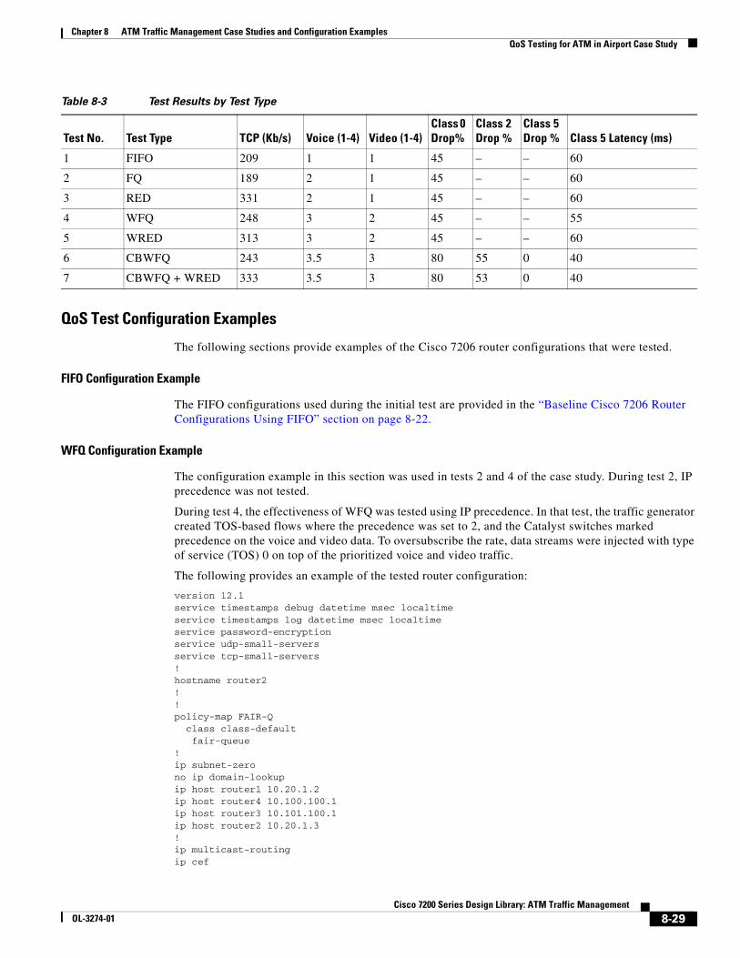
Eight variables were recorded during each test to demonstrate the effectiveness of each configuration, as shown in the summary of results in Table 8-3 on page 8-29:
• TCP data throughput
• Voice quality (rating of 1–4, with 4 being toll quality)
• Video quality (1–4)
• Drop percentage of class 0 traffic
• Drop percentage of class 2 traffic
• Drop percentage of class 5 traffic
• Data latency of class 5 traffic during congestion
• CPU utilization
Results Summary
The case objectives were met and the results exceeded expectations. Even during three-to-one bandwidth oversubscription, priority traffic was relatively unaffected while best effort traffic was discarded. CPU utilization remained well within acceptable limits.
8-28Cisco 7200 Series Design Library: ATM Traffic Management
OL-3274-01
Chapter 8 ATM Traffic Management Case Studies and Configuration Examples QoS Testing for ATM in Airport Case Study
Table 8-3 Test Results by Test Type
QoS Test Configuration Examples
The following sections provide examples of the Cisco 7206 router configurations that were tested.
FIFO Configuration Example
The FIFO configurations used during the initial test are provided in the “Baseline Cisco 7206 Router Configurations Using FIFO” section on page 8-22.
WFQ Configuration Example
The configuration example in this section was used in tests 2 and 4 of the case study. During test 2, IP precedence was not tested.
During test 4, the effectiveness of WFQ was tested using IP precedence. In that test, the traffic generator created TOS-based flows where the precedence was set to 2, and the Catalyst switches marked precedence on the voice and video data. To oversubscribe the rate, data streams were injected with type of service (TOS) 0 on top of the prioritized voice and video traffic.
The following provides an example of the tested router configuration:
version 12.1service timestamps debug datetime msec localtimeservice timestamps log datetime msec localtimeservice password-encryptionservice udp-small-serversservice tcp-small-servers!hostname router2!!policy-map FAIR-Q class class-default fair-queue!ip subnet-zerono ip domain-lookupip host router1 10.20.1.2ip host router4 10.100.100.1ip host router3 10.101.100.1ip host router2 10.20.1.3!ip multicast-routingip cef
Test No. Test Type TCP (Kb/s) Voice (1-4) Video (1-4)Class 0 Drop%
Class 2 Drop %
Class 5 Drop % Class 5 Latency (ms)
1 FIFO 209 1 1 45 – – 60
2 FQ 189 2 1 45 – – 60
3 RED 331 2 1 45 – – 60
4 WFQ 248 3 2 45 – – 55
5 WRED 313 3 2 45 – – 60
6 CBWFQ 243 3.5 3 80 55 0 40
7 CBWFQ + WRED 333 3.5 3 80 53 0 40
8-29Cisco 7200 Series Design Library: ATM Traffic Management
OL-3274-01

Chapter 8 ATM Traffic Management Case Studies and Configuration Examples QoS Testing for ATM in Airport Case Study
cns event-service server!!!vc-class atm 6Mbs vbr-nrt 5950 5900 32 oam-pvc manage 3 oam retry 5 3 3 encapsulation aal5snap!interface Loopback0 ip address 10.20.254.100 255.255.255.255 ip pim sparse-dense-mode!interface FastEthernet0/0 ip address 172.26.67.12 255.255.240.0 no ip proxy-arp no ip mroute-cache shutdown half-duplex!interface ATM3/0 no ip address atm pvc 1 0 5 qsaal atm pvc 2 0 16 ilmi no atm ilmi-keepalive!interface ATM3/0.1 multipoint description Client ELAN simulating Case Airline User ELAN ip address 10.20.1.3 255.255.255.0 no ip redirects ip pim sparse-dense-mode lane client ethernet elan1 standby 2 timers 1 5 standby 2 priority 150 preempt delay 60 standby 2 ip 10.20.1.1!interface ATM3/0.2 multipoint description server ELAN simulating Case Airline CORIP ip address 10.20.2.3 255.255.255.0 ip helper-address 10.20.1.101 no ip redirects ip pim sparse-dense-mode lane client ethernet elan2 standby 1 timers 1 5 standby 1 priority 110 preempt delay 60 standby 1 ip 10.20.2.1!interface ATM4/0 no ip address load-interval 30 no atm ilmi-keepalive!interface ATM4/0.1 point-to-point bandwidth 6000 ip address 10.101.2.1 255.255.255.0 ip pim sparse-dense-mode pvc 200/200 class-vc 6Mbs service-policy output FAIR-Q !!router ospf 1 log-adjacency-changes
8-30Cisco 7200 Series Design Library: ATM Traffic Management
OL-3274-01

Chapter 8 ATM Traffic Management Case Studies and Configuration Examples QoS Testing for ATM in Airport Case Study
area 100 stub no-summary area 100 range 10.100.0.0 255.255.0.0 area 101 stub no-summary area 101 range 10.101.0.0 255.255.0.0 redistribute static subnets network 10.20.0.0 0.0.255.255 area 0 network 10.100.0.0 0.0.255.255 area 100 network 10.101.0.0 0.0.255.255 area 101!ip default-gateway 172.26.64.1ip classlessip route 172.26.11.0 255.255.255.0 10.20.1.4ip http serverip pim send-rp-announce Loopback0 scope 16ip pim send-rp-discovery Loopback0 scope 5![text omitted]!end
WRED Configuration Example
The following configuration example was used in tests 3 and 5 of the case study. During test 3, IP precedence was not tested.
During test 5, the effectiveness of WFQ was tested using IP precedence. In that test, the traffic generator created TOS-based flows including prioritized voice, video, and TCP data. To oversubscribe the rate, data streams were injected with TOS 0 on top of the prioritized voice and video traffic.
The following provides an example of the tested router configuration:
version 12.1service timestamps debug datetime msec localtimeservice timestamps log datetime msec localtimeservice password-encryptionservice udp-small-serversservice tcp-small-servers!hostname router2!policy-map RED class class-default bandwidth 4200 random-detect!ip subnet-zerono ip domain-lookupip host router1 10.20.1.2ip host router4 10.100.100.1ip host router3 10.101.100.1ip host router2 10.20.1.3!ip multicast-routingip cefcns event-service server!!!!!vc-class atm 6Mbs vbr-nrt 5950 5900 32 oam-pvc manage 3
8-31Cisco 7200 Series Design Library: ATM Traffic Management
OL-3274-01

Chapter 8 ATM Traffic Management Case Studies and Configuration Examples QoS Testing for ATM in Airport Case Study
oam retry 5 3 3 encapsulation aal5snap!interface Loopback0 ip address 10.20.254.100 255.255.255.255 ip pim sparse-dense-mode!interface ATM3/0 no ip address atm pvc 1 0 5 qsaal atm pvc 2 0 16 ilmi no atm ilmi-keepalive!interface ATM3/0.1 multipoint description Client ELAN simulating Case Airline User ELAN ip address 10.20.1.3 255.255.255.0 no ip redirects ip pim sparse-dense-mode lane client ethernet elan1 standby 2 timers 1 5 standby 2 priority 150 preempt delay 60 standby 2 ip 10.20.1.1!interface ATM3/0.2 multipoint description server ELAN simulating Case Airline CORIP ip address 10.20.2.3 255.255.255.0 ip helper-address 10.20.1.101 no ip redirects ip pim sparse-dense-mode lane client ethernet elan2 standby 1 timers 1 5 standby 1 priority 110 preempt delay 60 standby 1 ip 10.20.2.1!interface ATM4/0 no ip address load-interval 30 no atm ilmi-keepalive!interface ATM4/0.1 point-to-point bandwidth 6000 ip address 10.101.2.1 255.255.255.0 ip pim sparse-dense-mode pvc 200/200 class-vc 6Mbs service-policy output RED !router ospf 1 log-adjacency-changes area 100 stub no-summary area 100 range 10.100.0.0 255.255.0.0 area 101 stub no-summary area 101 range 10.101.0.0 255.255.0.0 redistribute static subnets network 10.20.0.0 0.0.255.255 area 0 network 10.100.0.0 0.0.255.255 area 100 network 10.101.0.0 0.0.255.255 area 101!ip default-gateway 172.26.64.1ip classlessip route 172.26.11.0 255.255.255.0 10.20.1.4ip http serverip pim send-rp-announce Loopback0 scope 16ip pim send-rp-discovery Loopback0 scope 5
8-32Cisco 7200 Series Design Library: ATM Traffic Management
OL-3274-01

Chapter 8 ATM Traffic Management Case Studies and Configuration Examples QoS Testing for ATM in Airport Case Study
!!![text omitted]!end
Class-Based Weighted Fair Queueing (CBWFQ) Configuration with IP Precedence
The following configuration example was used in test 6 of the case study. During this test, the effectiveness of CBWFQ was measured with IP precedence. Three classes were configured to differentiate service levels based on IP precedence settings of 0, 2, and 5. Traffic was generated with the three IP precedence settings, and precedence was marked on voice and video traffic. To oversubscribe the rate, data streams were injected with TOS 0 on top of the prioritized voice, video, and TCP data traffic.
The following provides an example of the tested router configuration:
version 12.1service timestamps debug datetime msec localtimeservice timestamps log datetime msec localtimeservice password-encryptionservice udp-small-serversservice tcp-small-servers!hostname router2!class-map CLASS5 match access-group name IP-PRES5class-map CLASS2 match access-group name IP-PRES2class-map CLASS0 match access-group name IP-PRES0!!policy-map TOS-WFQ class CLASS0 bandwidth percent 10 class CLASS2 bandwidth percent 25 class CLASS5 priority 2500!ip subnet-zerono ip domain-lookupip host router1 10.20.1.2ip host router4 10.100.100.1ip host router3 10.101.100.1ip host router2 10.20.1.3!ip multicast-routingip cefcns event-service server!!!!!vc-class atm 6Mbs vbr-nrt 5950 5900 32 oam-pvc manage 3 oam retry 5 3 3 encapsulation aal5snap
8-33Cisco 7200 Series Design Library: ATM Traffic Management
OL-3274-01

Chapter 8 ATM Traffic Management Case Studies and Configuration Examples QoS Testing for ATM in Airport Case Study
!interface Loopback0 ip address 10.20.254.100 255.255.255.255 ip pim sparse-dense-mode!interface ATM3/0 no ip address atm pvc 1 0 5 qsaal atm pvc 2 0 16 ilmi no atm ilmi-keepalive!interface ATM3/0.1 multipoint description Client ELAN simulating Case Airline User ELAN ip address 10.20.1.3 255.255.255.0 no ip redirects ip pim sparse-dense-mode lane client ethernet elan1 standby 2 timers 1 5 standby 2 priority 150 preempt delay 60 standby 2 ip 10.20.1.1!interface ATM3/0.2 multipoint description server ELAN simulating Case Airline CORIP ip address 10.20.2.3 255.255.255.0 ip helper-address 10.20.1.101 no ip redirects ip pim sparse-dense-mode lane client ethernet elan2 standby 1 timers 1 5 standby 1 priority 110 preempt delay 60 standby 1 ip 10.20.2.1!interface ATM4/0 no ip address load-interval 30 no atm ilmi-keepalive!interface ATM4/0.1 point-to-point bandwidth 6000 ip address 10.101.2.1 255.255.255.0 ip pim sparse-dense-mode pvc 200/200 class-vc 6Mbs service-policy output TOS-WFQ !!router ospf 1 log-adjacency-changes area 100 stub no-summary area 100 range 10.100.0.0 255.255.0.0 area 101 stub no-summary area 101 range 10.101.0.0 255.255.0.0 redistribute static subnets network 10.20.0.0 0.0.255.255 area 0 network 10.100.0.0 0.0.255.255 area 100 network 10.101.0.0 0.0.255.255 area 101!ip default-gateway 172.26.64.1ip classlessip route 172.26.11.0 255.255.255.0 10.20.1.4ip http serverip pim send-rp-announce Loopback0 scope 16ip pim send-rp-discovery Loopback0 scope 5!
8-34Cisco 7200 Series Design Library: ATM Traffic Management
OL-3274-01

Chapter 8 ATM Traffic Management Case Studies and Configuration Examples QoS Testing for ATM in Airport Case Study
!ip access-list extended IP-PRES0 permit ip any any precedence 0ip access-list extended IP-PRES3 permit ip any any precedence 3ip access-list extended IP-PRES5 permit ip any any precedence 5![text omitted]!end
Hybrid Configuration Example Using WRED at City HQ and WFQ at Remote Airports
The final test (test 7) used WRED at City HQ and WFQ at the remote airports. RED was used for low priority TCP traffic with four classes used to define the three TOS-based classes, and a fourth class to match TOS 0 and the TCP protocol. Four traffic flows were tested across the different classes with voice, video, and data traffic. To oversubscribe the rate, data streams were injected with TOS 0 on top of the prioritized voice, video, and TCP data traffic.
The following provides an example of the tested router configuration:
Current configuration:!version 12.1service timestamps debug datetime msec localtimeservice timestamps log datetime msec localtimeservice password-encryptionservice udp-small-serversservice tcp-small-servers!hostname router2!!class-map CLASS0-TCP match access-group name TCP-CLASS0class-map CLASS2-TCP match access-group name TCP-CLASS2class-map CLASS5 match access-group name IP-PRES5class-map CLASS2 match access-group name IP-PRES2class-map CLASS0 match access-group name IP-PRES0!policy-map TOS-HYBR class CLASS0-TCP bandwidth percent 5 random-detect class CLASS0 bandwidth percent 10 class CLASS2 bandwidth percent 25 class CLASS5 priority 2500 class class-default fair-queue!ip subnet-zerono ip domain-lookupip host router1 10.20.1.2ip host router4 10.100.100.1ip host router3 10.101.100.1
8-35Cisco 7200 Series Design Library: ATM Traffic Management
OL-3274-01
Chapter 8 ATM Traffic Management Case Studies and Configuration Examples QoS Testing for ATM in Airport Case Study
ip host router2 10.20.1.3!ip multicast-routingip cefcns event-service server!!!!!vc-class atm 6Mbs vbr-nrt 5950 5900 32 oam-pvc manage 3 oam retry 5 3 3 encapsulation aal5snap!interface Loopback0 ip address 10.20.254.100 255.255.255.255 ip pim sparse-dense-mode!interface ATM3/0 no ip address atm pvc 1 0 5 qsaal atm pvc 2 0 16 ilmi no atm ilmi-keepalive!interface ATM3/0.1 multipoint description Client ELAN simulating Case Airline User ELAN ip address 10.20.1.3 255.255.255.0 no ip redirects ip pim sparse-dense-mode lane client ethernet elan1 standby 2 timers 1 5 standby 2 priority 150 preempt delay 60 standby 2 ip 10.20.1.1!interface ATM3/0.2 multipoint description server ELAN simulating Case Airline CORIP ip address 10.20.2.3 255.255.255.0 ip helper-address 10.20.1.101 no ip redirects ip pim sparse-dense-mode lane client ethernet elan2 standby 1 timers 1 5 standby 1 priority 110 preempt delay 60 standby 1 ip 10.20.2.1!interface ATM4/0 no ip address load-interval 30 no atm ilmi-keepalive!interface ATM4/0.1 point-to-point bandwidth 6000 ip address 10.101.2.1 255.255.255.0 ip pim sparse-dense-mode pvc 200/200 class-vc 6Mbs service-policy output TOS-HYBR !!router ospf 1 log-adjacency-changes area 100 stub no-summary
8-36Cisco 7200 Series Design Library: ATM Traffic Management
OL-3274-01

Chapter 8 ATM Traffic Management Case Studies and Configuration Examples QoS for AVVID Services over Low-Speed ATM VCs Configuration Example
area 100 range 10.100.0.0 255.255.0.0 area 101 stub no-summary area 101 range 10.101.0.0 255.255.0.0 redistribute static subnets network 10.20.0.0 0.0.255.255 area 0 network 10.100.0.0 0.0.255.255 area 100 network 10.101.0.0 0.0.255.255 area 101!ip default-gateway 172.26.64.1ip classlessip route 172.26.11.0 255.255.255.0 10.20.1.4ip http serverip pim send-rp-announce Loopback0 scope 16ip pim send-rp-discovery Loopback0 scope 5!!ip access-list extended IP-PRES0 permit ip any any precedence 0ip access-list extended IP-PRES2 permit ip any any precedence 2ip access-list extended IP-PRES5 permit ip any any precedence 5ip access-list extended TCP-CLASS0 permit tcp any any precedence 0![text omitted]^Cend
Case ConclusionsFrom the seven QoS test configurations explored in this case, the following conclusions were drawn:
• You can mark traffic with a higher precedence bit and implement QoS in a way that guarantees that preferred traffic preempts lower priority traffic even during periods of congestion, up to the total link bandwidth.
• Higher classes of traffic pass through the network with a lower latency than lower class traffic during periods of network congestion.
• Deploying RED for TCP data flows is an effective way to signal TCP end nodes to reduce the window size and to increase overall throughput of TCP during periods of congestion.
• CBWFQ is necessary to differentiate data flows from the same device that might have differing priorities.
QoS for AVVID Services over Low-Speed ATM VCs Configuration Example
In a VoIP network, voice quality is tightly coupled with packet loss, delay, and jitter. Therefore, network engineers must design enterprise networks with the objective of eliminating VoIP packet loss, and minimization of packet delay and jitter. To do this, you must use QoS in every part of the network. Specifically, it requires you to implement advance queueing and scheduling techniques in the distribution and core areas of the network, as well as in the WAN. Because WAN links are usually the lowest-speed circuits in an Architecture for Voice, Video, and Integrated Data (AVVID) network, you
8-37Cisco 7200 Series Design Library: ATM Traffic Management
OL-3274-01

Chapter 8 ATM Traffic Management Case Studies and Configuration Examples QoS for AVVID Services over Low-Speed ATM VCs Configuration Example
need to give particular attention to reducing loss, delay, and jitter across the WAN links. WAN aggregation routers are often taxed by maintaining large routing tables for remote branches. Therefore, it is also important to consider the CPU overhead of queueing mechanisms at the WAN edge.
Figure 8-4 shows a typical AVVID deployment over low-speed ATM VCs running at or below 768 Kbps in a WAN aggregation, enterprise network environment.
Figure 8-4 Low-Speed WAN Aggregation Example
In this example, the hub is a Cisco 7200 series router, and the remote routers are Cisco 2600 multiservice access routers. To implement the configuration , all routers require a minimum of Cisco IOS Release 12.2 T.
Table 8-4 provides the recommended configuration guidelines in this environment:
ATM<_768 Kbps PVCs
Hub
Remotes
7200
26002600 26002600 8918
2
Table 8-4 Configuration Guidelines for AVVID on Low-Speed ATM VCs
Configuration Area Recommendation
IP Precedence Use the following classifications:
• Voice media—IP precedence 5 or DSCP EF
• Voice control—IP precedence 3 or DSCP AF31
• Mission-critical traffic—IP precedence 2 or DSCP AF21
MLPPP over ATM Use Multilink PPP (MLPPP) over ATM for fragmentation if you are using VCs at or below 768 Kbps.
Per-VC Low Latency Queueing (LLQ) Enable priority queueing (PQ) for voice and Class-Based Weighted Fair Queueing (CBWFQ) for other classes of traffic on a per-VC basis.
Traffic Shaping Shape the PVC to a rate that is appropriate for the service contract with your service provider and the ATM policing performed to enforce it.
Transmit Ring Size Adjust the tx-ring-limit command for all ATM links below DS-3 speeds.
8-38Cisco 7200 Series Design Library: ATM Traffic Management
OL-3274-01

Chapter 8 ATM Traffic Management Case Studies and Configuration Examples QoS for AVVID Services over Low-Speed ATM VCs Configuration Example
Note The following partial examples are abbreviated to show the most relevant pieces of the configuration.
Cisco 7200 Series Router Configuration !ip cef!class-map Voice match ip precedence 5class-map Call-Control match ip precedence 3class-map Mission-Critical match ip precedence 2!! Policy-map example assumes 768k link speed and 45% (of 768K shaped rate) for LLQ !policy-map QoS-Policy-768k class Voice priority 328 class Call-Control bandwidth percent 10 class Mission-Critical bandwidth percent 20 class class-default fair-queue!interface ATM5/0 no ip address no ip mroute-cache no atm ilmi-keepalive!! This example shows the use of abr for ATM VC; other possibilities (e.g. vbr-nrt) exist!interface ATM5/0.37 point-to-point pvc cisco37 100/37 tx-ring-limit 3 abr 768 768 protocol ppp Virtual-Template37 !!interface Virtual-Template37 bandwidth 768 ip address 10.1.37.2 255.255.255.252 service-policy output QoS-Policy-768k ppp multilink ppp multilink fragment-delay 10 ppp multilink interleave
!
Cisco 2600 Series Router Configuration!ip cef!class-map Voice match ip precedence 5class-map Call-Control match ip precedence 3class-map Mission-Critical match ip precedence 2!! Policy-map example assumes 768K link speed and 45% (of shaped 768K rate) for LLQ
8-39Cisco 7200 Series Design Library: ATM Traffic Management
OL-3274-01

Chapter 8 ATM Traffic Management Case Studies and Configuration Examples QoS for AVVID Services over Low-Speed ATM VCs Configuration Example
!policy-map QoS-Policy-768k class Voice priority 328 class Call-Control bandwidth percent 10 class Mission-Critical bandwidth percent 20 class class-default fair-queue!interface ATM2/0 no ip address no ip mroute-cache no atm ilmi-keepalive!! This example shows the use of abr for ATM VC; other possibilities (e.g. vbr-nrt) exist!interface ATM2/0.37 point-to-point pvc cisco37 100/37 tx-ring-limit 3 abr 768 768 protocol ppp Virtual-Template1 !!interface Virtual-Template1 bandwidth 768 ip address 10.1.37.1 255.255.255.252 service-policy output QoS-Policy-768k ppp multilink ppp multilink fragment-delay 10 ppp multilink interleave!
8-40Cisco 7200 Series Design Library: ATM Traffic Management
OL-3274-01