at-series anchor instructions
TRANSCRIPT

Copyright © 2018 Aqua Creek Products All Rights Reserved Revised 6/4/18
AT-Series Anchor Instructions
PART #: F-04CAJP
Pro Pool Lift - Weight Capacity (450 LBS) / Max Setback (19”)Pro Pool Lift Ext Base 23” - Weight Capacity (450 LBS) / Max Setback (23”)Pro Pool Lift Ext Base 26” - Weight Capacity (450 LBS) / Max Setback (26”)Pro Pool Lift Deep Draft - Weight Capacity (400 LBS) / Max Setback (17”)
Ranger Lift - Weight Capacity (350 LBS) / Max Setback (19”)
MANDATORY LEAVE THIS MANUAL WITH LIFT OWNER
Read and follow all instructions.Lift safety can only be ensured if the lift is installed
and operated according to these instructions.
• NEVER permit children to play on or around the lift• Do not allow children to use the lift without adult supervision• NEVER apply direct water pressure to the electronics• NEVER use the lift with a dry pool
9889 Garrymore LnMissoula, MT 59808
888-687-3552 | +1-406-549-0769www.aquacreek.com
Check entire box and all packing materials for parts. Before beginning assembly, read the instructionsandidentifypartsusingthefiguresandpartslistedinthisdocument.
It is critical that all parts be carefully inspected prior to installation. If any damage occurred in transit,AquaCreekProducts,LLCmustbenotifiedwithinthreedaysofreceiptofunit.
Proper installation cannot be overstressed, as an improper installation voids Aqua Creek’s warranty and may affect the safety of the user.
READ CAREFULLY
1

Copyright © 2018 Aqua Creek Products All Rights Reserved Revised 6/4/18
F-04CAJP: AT Anchor Assembly Parts List
ITEM # QTY PART # DESCRIPTION1 4 BH 1/2 X 1-1/2 BOLT, 316 SS, 1/2-13 X 1 1/2 HCS
2 4 WF 1/2 WASHER, FLAT, 1/2, 316 SS
3 1 WT 1/2 WASHER, 316 SS, 1/2” EXTERNAL TOOTH
4 3 P-7200ANB ANCHOR INSERT, NON-BONDABLE
5 1 P-7200ANB-BB ANCHOR INSERT, BONDABLE
6 8 NH 1 ZINC NUT, ZINC, HEX, 1”-8
7 4 PIP-1/2-TAB TAB, PIP-1/2, BLACK CAP
8 1 WF 1/4 WASHER, FLAT, 1/4, 316 SS
9 1 SPH 1/4 X 3/4 BRASS SCREW, BRASS, 1/4-20 X 3/4” PANHEAD
10 1 ANTI SIEZE, PACKET, .75 ANTI SIEZE, PACKET, 5 GRAMS
ITEM # QTY PART # DESCRIPTION1 1 GBL-4DB LUG, IN GROUND BONDING LUG
2 1 P-004CPPJP-A JIG PLATE FOR PRO SERIES LIFTS
3 1 NN 10 NUT, 316 SS, NYLOCK, #10-24
4 1 BSH 10 X 3/4 BOLT, 316 SS, 10-24 X 3/4 SHCS
5 1 LABEL #97 REFER TO MANUAL FOR PROPER SETBACK3F-433JIG-AT
F-044ANI1
2
4
6
2
4
1
57
8
5
9
3
Front Anchor Setback Distance ChartLift Model Min Setback Max Setback
Pathfi nder 14.5” 16”Ranger 14.5” 19”
Pro Pool 14.5” 19”Pro Pool 23” Ext Base 19” 23”Pro Pool 26” Ext Base 23” 26”Pro Pool Deep Draft 14.5” 17”
Note: All setback distances are based on a straight pool wall. Setback distances will change for curved pool walls. Contact Aqua Creek for curved wall setback distances.
2

Copyright © 2018 Aqua Creek Products All Rights Reserved Revised 6/4/18
The AT ANCHOR ASSEMBLY will come fully disassembled. Review the diagram below to familiarize yourself with the components before beginning the installation. The anchor assembly is used in diff erent ways, depending on your type of installation. For instance the ANCHOR JIG-PLATE can be used as a template to mark the holes for retro-fi tting, to hold the ANCHOR INSERTS at the proper spacing as the epoxy cures (see RETROFIT INSTALLATION), or as a permanent part of the installed/embedded assembly.
The AT-Anchor Assembly
1/2" X 1-1/2"HEX BOLT (4)
1/2" FLATWASHER (3)
1" X 4"ANCHOR-INSERT (4)
1" HEX-NUT (8)
#10 X 3/4"HEX BOLT
GBL-4DBBONDING-
LUG
ANCHORJIG-PLATE
#10 NYLOCK
1/4 FLATWASHER
1/4 X 3/4PAN-HEADBOLT
1/2" EXTERNALTOOTH WASHER
3
Copyright © 2018 Aqua Creek Products All Rights Reserved Revised 6/4/18
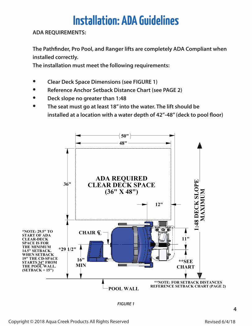
Installation: ADA GuidelinesADA REQUIREMENTS:
The Pathfi nder, Pro Pool, and Ranger lifts are completely ADA Compliant when installed correctly. The installation must meet the following requirements:
• Clear Deck Space Dimensions (see FIGURE 1)• Reference Anchor Setback Distance Chart (see PAGE 2)• Deck slope no greater than 1:48• The seat must go at least 18” into the water. The lift should be installed at a location with a water depth of 42”-48” (deck to pool fl oor)
FIGURE 1
11"
36"
48"
12"
**SEECHART
*29 1/2"
16"MIN
50"
ADA REQUIREDCLEAR DECK SPACE
(36" X 48")1:
48 D
EC
K S
LO
PEM
AX
IMU
M
POOL WALL
CHAIR CL*NOTE: 29.5" TOSTART OF ADACLEAR-DECKSPACE IS FORTHE MINIMUM14.5" SETBACK.WHEN SETBACK19" THE CD-SPACESTARTS 34" FROMTHE POOL WALL.(SETBACK + 15")
**NOTE: FOR SETBACK DISTANCESREFERENCE SETBACK CHART (PAGE 2)
4

Copyright © 2018 Aqua Creek Products All Rights Reserved Revised 6/4/18
Anchor Installation: Core-drill Retro-fitNOTE: FOR DECKS 6” THICK OR MORE, 2500PSI MINIMUM STRENGTH CONCRETE REQUIRED
You will need:• Core drill and 1 ½” core drill bit• Tape measure• Marking pen• Hammer• Cold chisel• Torpedo level• High strength 2-part construction epoxy*• Masking tape• Black electrical tape (optional)
*Aqua Creek recommends either Hilti™ Brand HIT RE-500-SD or Simpson™ brand SET-XP or equivalent (not
included)Anchor jig plate with hardware
1. Mark the 4 hole locations on your deck using the larger holes of the anchor jig plate as a template. Make sure the center of the holes on the anchor jig plate are aligned according to your lifts setback distance. SEE PAGE 2.
2. Drill out the 4 hole locations to about 4 ½ inches deep using the 11/2 inch drill bit. Make sure the holes are completely dry and clear of debris.
NOTE: Create a depth marker on the drill bit with black electri-cal tape to make sure you drill to the right depth
NOTE: Your local bonding regulations may require you drill one hole larger than the others in order to bond at least one of the anchor inserts. You may need to saw cut a portion of your deck.
See “Saw Cutting Retro-Fit Instructions” on page 7.
3. Remove the nuts and the black protective coverings from the threaded anchor inserts.
FIGURE 2
continued on page 65

Copyright © 2018 Aqua Creek Products All Rights Reserved Revised 6/4/18
Anchor Installation: Core-drill Retro-fit (CONTINUED)
4. Thread the mounting hardware through the smaller anchor plate holes and into the anchor inserts. Make sure to use Anti-seize on the threads! Make sure the tops of the inserts are flush with the bottom of the plate.
NOTE: We recommend using masking tape around the holes on the bottom of the anchor jig plate to help prevent
the anchor plate from being accidentally epoxied to the pool deck.
5. Bond at least one of the anchor inserts according to your local code requirements. For more information see NEC Article 680.26.
6. Test fit the anchor inserts to make sure they line up properly. Place the anchor assembly into the pre-drilled holes and use a torpedo level to check if your anchoring system will be level.
7. Remove the anchor assembly and fill each hole halfway full with 2-part construction epoxy.
8. Place the anchor assembly back into the holes. Wiggle the assembly as you reinsert it to make sure the epoxy fully coats the threads.
9. Make sure your anchor assembly is level.
10. Once the epoxy has set up remove the hardware and the anchor jig plate. Your lift is now ready to be mounted to the anchoring system. The anchor jig plate may be recycled and/or used to install other anchors.
6

Copyright © 2018 Aqua Creek Products All Rights Reserved Revised 6/4/18
FIGURE C
Anchor Installation: Saw-cut Retro-fi t
FIGURE B
Bonding Lug• Concrete saw with diamond blade• Tape measure• 4’ long straight edge or chalk line• Sledge hammer• Cold chisel
• Torpedo level• String Line• Concrete & concrete fi nishing tools• #5 rebar
You Will Need:
4"
6"
FLUSH W-DECK
#5 REBAR EACH WAYDRILL & EPOXY INTO EXISTING
SLAB (4" MIN EMBED)
2500PSI MIN
48"
2.5"MIN
*REFERENCE SETBACKDISTANCE CHART
(PAGE 2)
48"
LABEL
BONDING-LUG
POOLWALL
8-AWG SOLID-COPPER WIRE(ATTACH TO BONDING-GRID)
#5REBAR
FIGURE A
1. Remove 1 nut from each anchor insert. Place the anchor inserts through the larger hole of the anchor jig plate. Thread the removed nuts back onto the anchor inserts. The anchor plate should be sandwiched between the two nuts on each anchor insert. SEE FIGURE C
2. Mark out a section of the pool deck you are removing. Plan on removing at least 4’ x 4’ x 6” deep. It must be reinforced with 5 sticks of #5 rebar E-W, 2” clear (min) from the top and bottom of the footing.
3. Cut along your marks with a diamond blade concrete saw.
4. Using the sledge hammer, break up the concrete within the area you cut and remove the pieces. 6. Install rebar in the open area of the deck. Tie the rebar into the existing deck if possible. SEE FIGURE B
7. Set the anchor system in place. Make sure the center of the large anchor jig plate holes aren’t set back further than the max distance provided on page 2.
8. Using the string line or a straight edge, make sure the top of each anchor body is level with the FINISHED deck surface. Each anchor body can be adjusted individually by turning the nuts with a large wrench.
9. Bond the anchoring system according to your local code requirements by using the bonding lug on the anchor plate. SEE FIGURE A (See NEC Article 680.26)
10. Pour your concrete and fi nish the pool deck surface. SEE FIGURE C
11. Once the concrete has cured, your lift is ready to be mounted to the anchoring system. SEE FIGURE C 7

Copyright © 2018 Aqua Creek Products All Rights Reserved Revised 6/4/18
1. Remove 1 nut from each anchor insert. Place the anchor inserts through the larger hole of the anchor jig plate. Thread the removed nuts back onto the anchor inserts. The anchor plate should be sandwiched be-tween the two nuts on each anchor insert. SEE FIGURE C
2. Install rebar in the open area of the deck. SEE FIGURE B
3. Set the anchor system in place. Make sure the center of the large anchor jig plate holes aren’t set back further than the max distance provided on page 2.
4. Make sure the top of each anchor body is fl ush with the FINISHED deck surface. Each anchor body can be adjusted individually by turning the nuts with a large wrench.
5. Bond the anchoring system by using the bond-ing lug on the anchor plate. Bond the system according to your local code requirements. SEE FIGURE A (See NEC Article 680.26)
6. Pour your concrete and fi nish the pool deck surface. SEE FIGURE C
7. Once the concrete has cured your lift is ready to be mounted to the anchoring system. SEE FIGURE C
Anchor Installation: New Construction
FIGURE B
FIGURE C
NOTE: For installations where a new deck is being poured, or where a dedicated pad is being poured just for the pool lift, the concrete must satisfy the ADA requirements outlined on page 4 of this manual.
4"
6"
FLUSH W-DECK
#5 REBAR EACH WAYDRILL & EPOXY INTO EXISTING
SLAB (4" MIN EMBED)
2500PSI MIN
48"
2.5"MIN
*REFERENCE SETBACKDISTANCE CHART
(PAGE 2)
48"
LABEL
BONDING-LUG
POOLWALL
8-AWG SOLID-COPPER WIRE(ATTACH TO BONDING-GRID)
#5REBAR
FIGURE A
Your pool deck must be at least 4’ x 4’ x 6”. It must be reinforced with 5 sticks of #5 rebar E-W, 2” clear (min) from the top and bottom of the footing.
8
Copyright © 2018 Aqua Creek Products All Rights Reserved Revised 6/4/18
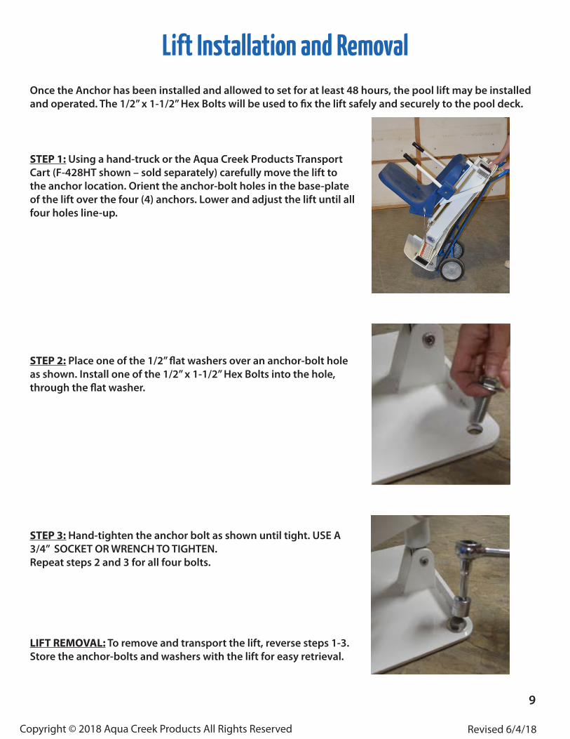
Lift Installation and RemovalOnce the Anchor has been installed and allowed to set for at least 48 hours, the pool lift may be installed and operated. The 1/2” x 1-1/2” Hex Bolts will be used to fix the lift safely and securely to the pool deck.
STEP 1: Using a hand-truck or the Aqua Creek Products Transport Cart (F-428HT shown – sold separately) carefully move the lift to the anchor location. Orient the anchor-bolt holes in the base-plate of the lift over the four (4) anchors. Lower and adjust the lift until all four holes line-up.
STEP 2: Place one of the 1/2” flat washers over an anchor-bolt hole as shown. Install one of the 1/2” x 1-1/2” Hex Bolts into the hole, through the flat washer.
STEP 3: Hand-tighten the anchor bolt as shown until tight. USE A 3/4” SOCKET OR WRENCH TO TIGHTEN. Repeat steps 2 and 3 for all four bolts.
LIFT REMOVAL: To remove and transport the lift, reverse steps 1-3. Store the anchor-bolts and washers with the lift for easy retrieval.
9