asynchronous design seminar at university of verona
TRANSCRIPT

6/15/2016
1
Asynchronous Design Seminar at
University of Verona – Lecture Notes 5
Asynchronous Control Circuits – One-Hot FSMs and PTnetTheory
Contents
One-Hot FSM Templates
Linear States
Choice States
Hollaar’s and David’s Approaches
SI vs. non SI operation during State Transitions
Extensions to PTnets
Fork/Join Structures
Hazard-freeness of Combinational Logic
How to check?
Asynchronous Control Circuit Design - L5 6/29/20152

6/15/2016
2
One-Hot/One-Cold Encoding
6/29/2015Asynchronous Control Circuit Design - L53
What is unique to One-Hot/One-Cold State Codes?State Number Sequential
Encoding
Gray
Encoding
Johnson Encoding One-hot Encoding
0 0000 0000 00000000 0000000000000001
1 0001 0001 00000001 0000000000000010
2 0010 0011 00000011 0000000000000100
3 0011 0010 00000111 0000000000001000
4 0100 0110 00001111 0000000000010000
5 0101 0111 00011111 0000000000100000
6 0110 0101 00111111 0000000001000000
7 0111 0100 01111111 0000000010000000
8 1000 1100 11111111 0000000100000000
9 1001 1101 11111110 0000001000000000
10 1010 1111 11111100 0000010000000000
11 1011 1110 11111000 0000100000000000
12 1100 1010 11110000 0001000000000000
13 1101 1011 11100000 0010000000000000
14 1110 1001 11000000 0100000000000000
15 1111 1000 10000000 1000000000000000
One-Hot/One-Cold Encoding
6/29/2015Asynchronous Control Circuit Design - L54
One-Hot encoding is not actually an encoding per se
Simple and unique assignment of binary codes to symbolic states
Very commonly used in industry, why?
Fast in terms of CAD tools time no computation required with respect to binary encoding states
Fast in terms of circuit operation no encoding/decoding logic required in the fan-in/fan-out of state variables
One-Hot FSM is compositional easy to break to pieces
Disadvantage?
Number of binary signals linearly dependent on number of states
In many cases this is not a problem as FSMs are usually small
6/15/2016
3
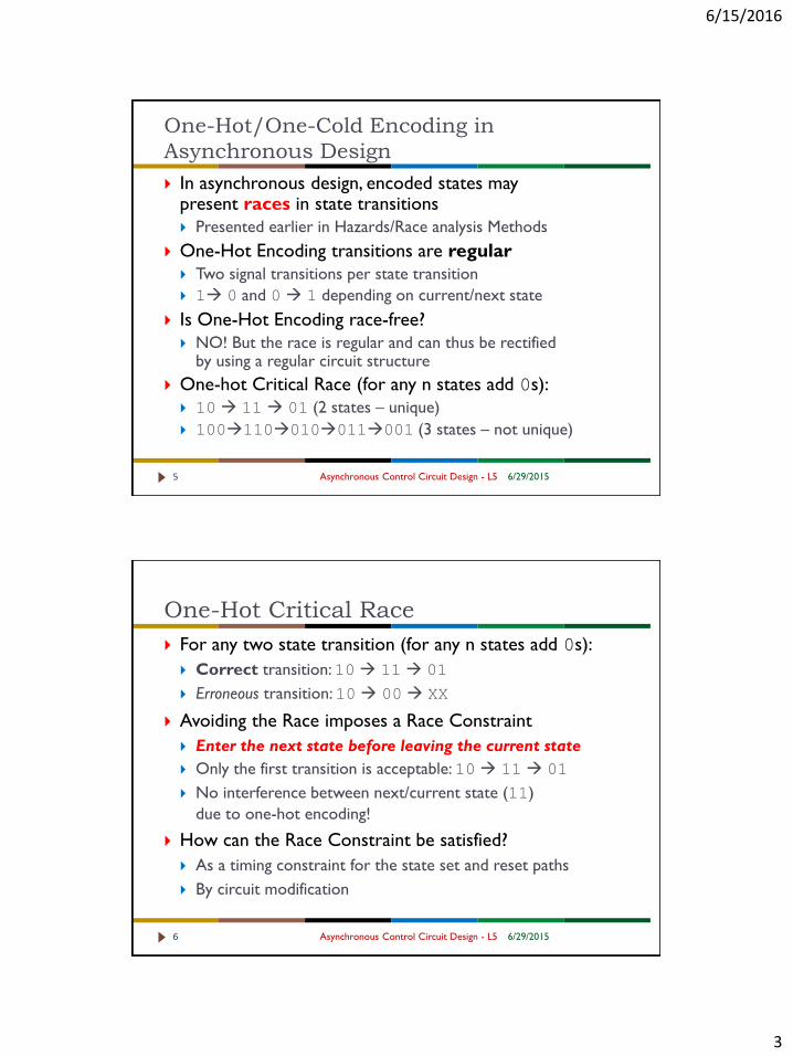
One-Hot/One-Cold Encoding in
Asynchronous Design
6/29/2015Asynchronous Control Circuit Design - L55
In asynchronous design, encoded states may present races in state transitions
Presented earlier in Hazards/Race analysis Methods
One-Hot Encoding transitions are regular
Two signal transitions per state transition
1 0 and 0 1 depending on current/next state
Is One-Hot Encoding race-free?
NO! But the race is regular and can thus be rectified by using a regular circuit structure
One-hot Critical Race (for any n states add 0s):
10 11 01 (2 states – unique)
100110010011001 (3 states – not unique)
One-Hot Critical Race
6/29/2015Asynchronous Control Circuit Design - L56
For any two state transition (for any n states add 0s):
Correct transition: 10 11 01
Erroneous transition: 10 00 XX
Avoiding the Race imposes a Race Constraint
Enter the next state before leaving the current state
Only the first transition is acceptable: 10 11 01
No interference between next/current state (11)
due to one-hot encoding!
How can the Race Constraint be satisfied?
As a timing constraint for the state set and reset paths
By circuit modification

6/15/2016
4
One-Hot FSMs
6/29/2015Asynchronous Control Circuit Design - L57
Regular Template Circuit Structure
State is SR Latch
Implemented using standard-cells or as a single latch cell
Set and Reset conditions implemented typically in 2-level Logic
Set condition = Previous State AND Enter Conditions for Current State
Reset condition = Next State (Entered)
May be implemented as SI or Fundamental Mode
Depends on Environment constraints
Depends on Local Timing constraints required for Correct
operation
One-Hot FSMs – Linear FSM Example
6/29/2015Asynchronous Control Circuit Design - L58
Each One-hot state
may be implemented
using an SR latch
Set input
State entering
conditions
Reset input
State exit conditions
Both Active-low due
to NAND SR latch
Regular Circuit
Structure!

6/15/2016
5
One-Hot FSMs – Choice FSM Example
6/29/2015Asynchronous Control Circuit Design - L59
Choice can easily be implemented
Reset condition for state s1 is the Set condition of s2 OR s3
Transforms to AND due to active-low Reset
Similarly for return from Choice
Reset for predecessors is Set of successor
Scale-of-Two Loops
6/29/2015Asynchronous Control Circuit Design - L510
For correct operation Set and Reset conditions must be Mutually-Exclusive
If the predecessor and successor states are the same this correctness condition is violated if Set/Reset conditions overlap in time
What if both x and z are high in RHS?

6/15/2016
6
Scale-of-Two Loops - Solutions
6/29/2015Asynchronous Control Circuit Design - L511
To ensure
Mutually-Exclusive
Set and Reset
signals we can
either:
Add
intermediate
dummy state (SI
operation)
Add transition
signals to Reset
conditions
(normally ignored)
One-Hot Race
6/29/2015Asynchronous Control Circuit Design - L512
Is this approach
Race-Free?
NO!!!
Why not?
It does not
enforce One-Hot
Race-Free
behaviour:
10 11 01
Can it be made Race-Free?

6/15/2016
7
One-Hot Race
6/29/2015Asynchronous Control Circuit Design - L513
Can it be made Race-Free?
Yes
Two approaches:
Ensure Set path is faster than Reset path (for two or more states!!!)
SI Solution:
Add a propagate gate (current state and NOT previous state)
PR = CS.PS’
Use PR_sn instead of sn
General One-Hot FSM State Structure
6/29/2015Asynchronous Control Circuit Design - L514
Propagate gate (pr_sn) ensures SI operation

6/15/2016
8
What about Hazards? Is this a Hazard-free
Approach?
6/29/2015Asynchronous Control Circuit Design - L515
It is possible for the Set and Reset Logic to contain Logic
Hazards
How can this be resolved?
Hazards may be analysed using Fundamental or SI Analysis
Techniques
Logic Hazards can be removed by restructuring Set/Reset
Logic
Other Observations about One-Hot FSMs
6/29/2015Asynchronous Control Circuit Design - L516
It is possible to extend One-Hot FSMs to model FSMs
with Forks and Joins!
Allow multiple One-hot states to be high between fork and
join states
How?
Modify reset conditions

6/15/2016
9
CMOS One-Hot FSMs
6/29/2015Asynchronous Control Circuit Design - L517
Possible to implement
One-Hot FSMs at
Transistor-Level
Set and Reset
Conditions become
Pull-up and Pull-
down networks of
State-storing gates
Example where CSC has no Solution!
6/29/2015Asynchronous Control Circuit Design - L518
DAC’06: Carmona and Cortadella: “State Encoding of Large Asynchronous Controllers”

6/15/2016
10
Contents
Fundamental Definitions
Net, Marking, etc.
PTnet Classes
Siphons/Deadlocks and Traps
Handles
S-Covers and T-Covers
An Algorithm for S-Covering FCPTnets
6/29/201519 Asynchronous Control Circuit Design - L5
PTnet Definitions
6/29/2015Asynchronous Control Circuit Design - L520
Definition [PTnet]:
A Place Transition net (or PTnet) is a triple N = (S, T, F), where
S is the set of places,
T is the set of transitions (S ∩T = Ø)
F ≤ (S x T) U (T x S) is the flow relation
Elements of S U T are called nodes
pre-set •x of x in (S U T) is given by
•x = {y in S U T | (y, x) in F}
post-set x• of x in (S U T) is given by
x• = {y in S U T | (x, y) in F}
A Marking M is a function M: SN
A Marked PTnet <N, M0> is a PTnet with an initial marking

6/15/2016
11
PTnet Definitions
6/29/2015Asynchronous Control Circuit Design - L521
A transition t in T is enabled at marking M iff:
For all p in •t: M(p) > 0
When t fires at M a new marking M’ is produced:
M’(p) = M(p) – F(p, t) + F(t, p) (F is characteristic function of F)
M[t>M’ denotes that M’ is reachable from M by the
occurrence of transition t
The set of markings reachable from the initial marking M0
by the occurrence of a sequence of transitions
σ = t1t2…tn =is denoted by R(N, M0)
PTnet Definitions – Net Subclasses
6/29/2015Asynchronous Control Circuit Design - L522
Definition [S-graph – State Machine]:
A net N = (S, T, F) is called an S-graph or State Machine, iff each
transition has exactly one input place and one output place
for all t in T: |•t| = 1 = |t•|
Definition [T-graph – Signal Transition Graph]:
A net N = (S, T, F) is called an T-graph or STG, iff each place has
exactly one input transition and one output transition
for all s in S: |•s| = 1 = |s•|

6/15/2016
12
Definition [Free-Choice]:
N is called free-choice iff all p in S such that |p•|>1,
•(p•) = p
Definition [Asymmetric-Choice]:
N is called asymmetric-choice (or simple net) iff for every twoplaces p1, p2, p1•∩ p2• ≠ Ø p1• ≤ p2• or p1• ≥ p2•
PTnet Definitions – Net Subclasses
6/29/2015Asynchronous Control Circuit Design - L523
PTnet Definitions – Net Subclasses
6/29/2015Asynchronous Control Circuit Design - L524
Definition [General PTnet]:
N is called general PTnet iff for every two placesp1, p2, p1•∩ p2• ≠ Ø p1• ≤ p2• or p1• ≥ p2•

6/15/2016
13
Asymmetric or Symmetric Confusion
6/29/2015Asynchronous Control Circuit Design - L525
Cases where Choice and
Concurrency are combined
are referred to as confusion
Symmetric Confusion
t1, t3 are concurrent but in
conflict with t2
Asymmetric Confusion
t1, t2 are in conflict,
if t3 fires before t1!
t1, t3 are concurrent
s1 s2
t1 t2 t3
t1 t2
t3s1 s2
s3
PTnet Classification Revisited
6/29/2015Asynchronous Control Circuit Design - L526
MG
SM FC
AC
PT

6/15/2016
14
PTnet Definitions - Subnets
6/29/2015Asynchronous Control Circuit Design - L527
Definition [S-Components and T-Components]:
N’ = (S’, T’, F’) is a subnet of N = (S, T, F) iffS’ ≤ S, T’ ≤ T and F’ = F ∩ ((S’ x T’) U (T’ x S’))
N’ is an S-component (T-component) of N iff
N’ is a strongly connected S-graph (T-graph) and|T’ = •S’∩S’• (S’ = •T’∩T’•).
N’ is generated by a set X’ ≤ S ∩T iff:
S’ = (X’ ∩ S) U •(X’ ∩T) U (X’ ∩T)•
T’ = (X’ ∩T) U •(X’ ∩ S) U (X’ ∩ S)•
PTnet Definitions – Behavioural Properties
6/29/2015Asynchronous Control Circuit Design - L528
Definition [Bounded Net]:
A marked net (N, M0) is bounded iff:
for all p in S, there exists k in N, s.t. for all markings M reachable from M0: M(p) ≤ k
Definition [Structurally Bounded Net]:
A net N is structurally bounded iff it is bounded for any initial marking M0.
Definition [Liveness]:
A transition t in T is live in (N, M0) iff:
For all M in R(N, M0) there exists M’ in R(N, M): M’ enables t.
The marked net (N, M0) is live iff all t in T are live.
N is structurally live iff there exists initial marking M0 such that (N, M0) is live

6/15/2016
15
PTnet Definitions – Graph Properties
6/29/2015Asynchronous Control Circuit Design - L529
Definition [Path]:
A path of a net N=(S, T, F) is an alternating sequence
π = (x0f0x1…fr-1xr) of elements X = S U T such that:
for all I, 0 ≤ i ≤ r – 1: fi = (xi, xi+1) in F
A path is elementary iff all xi are distinct except x0 and xr
A circuit is a path such that x0 = xr
A circuit is elementary iff it is elementary as a path
Definition[Alternating Circuit]
Let N = (S, T, F) be a net. A circuit Γ of N (not necessarily
elementary) is an alternating circuit iff for all arcs in Γ of the
form (p, t) the equality •t = {p} holds
PTnet Definitions - Subnets
6/29/2015Asynchronous Control Circuit Design - L530
Definition [Well-formed Net]:
A Net N is well-formed if there exists a marking M0 of N
such that (N, M0) is a live and bounded system
Thus, the net is not necessarily live at the current
marking…
Theorem [S-Components and Well-Formed Nets]:
Well formed Nets are covered by S-Components

6/15/2016
16
PTnet Definitions – Siphons and Traps
6/29/2015Asynchronous Control Circuit Design - L531
Definition [Siphons (Deadlocks) and Traps]:
Let N = (S, T, F) be a net.
D ≤ S is a siphon (deadlock) iff D ≠ Ø and •D ≤ D•
Θ ≤ S is a trap iff Θ ≠ Ø and Θ• ≤ •Θ
A siphon (deadlock) or trap is minimal iff
there exists no deadlock or trap D’ such that D’ ≤ D
A siphon (deadlock) or trap is strongly-connected iff
the subnet generated by D U •D is strongly connected
Commoner’s Theorem
An FC System is live iff each siphon contains a marked trap
Each cycle is marked
PTnet Definitions – Siphons and Traps
6/29/2015Asynchronous Control Circuit Design - L532
Theorem[Minimal Siphon for General PTnets]
Let N = (S, T, F) be a net, D ≤ S a siphon of N and ND the subnet of N
generated by D U •D.
D is minimal iff there exists a circuit Γ in ND (not necessarily elementary)
that passes through all places of D such that for every transition t in Γeither:
|•t ∩ D| = 1 (if net is FC) or
|•t ∩ D| ≥ 2 and the places of (•t ∩ D) belong to an
alternating circuit D
p1 p2

6/15/2016
17
PTnet Definitions – Siphons and Traps
6/29/2015Asynchronous Control Circuit Design - L533
The set {s1, s2} is a siphon; the set {s3, s4} is a trap
Siphon/Trap Examples
6/29/2015Asynchronous Control Circuit Design - L534
1:
s0 is a siphon (minimal)
s1 is a trap
2:
{s0, s1} is a siphon
NOT minimal,
as structurally {s0}, {s1} are also
siphons
s0 s1t0
s1
s2t0
s0
1
2

6/15/2016
18
Siphon/Trap Examples
6/29/2015Asynchronous Control Circuit Design - L535
Siphon
D = {s0, s1, s3}
•t0 = {s1, s3}
|•t0 ∩ {s1, s3}| = 2
D is not minimal
Minimal Siphon
{s0, s3}
t1
t3
t0
t2s0
s2
s1
s3
Siphon/Trap Examples
6/29/2015Asynchronous Control Circuit Design - L536
Minimal Siphon
{s0, s1}
Minimal Trap
{s2}s0
t0
t1
s3
s1 t2 s2

6/15/2016
19
Siphon/Trap Examples
6/29/2015Asynchronous Control Circuit Design - L537
Minimal Siphon
{s2}
Minimal Traps
{s4}, {s5}t3
t0
t1
s0 s1 s4
s2
t2
s3 t4 s5
Siphon/Trap Examples
6/29/2015Asynchronous Control Circuit Design - L538
Minimal Siphon
{s0, s1}
s0 s1
t0
t1
t2 s2
s4t3s3
s5
t4
s6
t5

6/15/2016
20
Siphon/Trap Examples
6/29/2015Asynchronous Control Circuit Design - L539
Minimal Siphons/Traps
{s0, s1}
{s3, s4}s0
t0
t1
s4
t2
t3
s1
s3
Siphon Example and Complexity
6/29/2015Asynchronous Control Circuit Design - L540
Places s0, s1, s3 are
choice places to all
others
Minimal Siphon
{s0, s1, s2}
Are NOT Siphons
{s0, s1}, {s1, s2}, {s0, s2}
{s0}, {s1}, {s2}
Complexity ~O(S, T)
s0
s2
s1

6/15/2016
21
Siphon Example and Complexity
6/29/2015Asynchronous Control Circuit Design - L541
Free-Choice structure between
multiple place siphons
Minimal siphons = {s0}, {s1}, {s3}
Siphons
{s0}, {s1}, {s3}
{s0, s1}, {s0, s2}, {s1, s2}
{s0, s1, s2}
The number of Siphons is
WC Exponential!
Should not aim to explore ALL siphons
s0
s1
s2
PTnet Definitions – Graph Properties
6/29/2015Asynchronous Control Circuit Design - L542
Definition [Handle]:
Let N’ be a partial subnet of N.
An elementary path π = (x0f0x1…fn-1xn) is a handle of N’
iff π ∩ N’ = {x0, xn}
…x0 xn
N-N’ N’

6/15/2016
22
PTnet Examples
PTnet Examples - 1
6/29/2015Asynchronous Control Circuit Design - L544
s1 s2
t2
t1
t3 s3
t4
t5
s2
t1
t2
s1t3
s4
s4
t4
B’, LB, L’
B, L
1. 2.

6/15/2016
23
PTnet Examples - 2
6/29/2015Asynchronous Control Circuit Design - L545
B’, L’
4. 5.
B’, L
PTnet Examples - 3
6/29/2015Asynchronous Control Circuit Design - L546
6.
B’, L’ B, L
7.

6/15/2016
24
Minimal Siphons and S-Components
– Esparsa/Kemper Algorithm
Get Handle Algorithm
6/29/2015Asynchronous Control Circuit Design - L548
N is strongly-connected FC-Net with S, S’ ≤ P U T
S ∩ S’ = Ø, p in S, t in S’, t is in •p, Outputs handle H = (x0, x1, …, xn-2, t, p) or 0
Num(v) values:
num(v) == -1 v in S, start point of handle, num(v) ==0 v in S’, not visited before
num(v) > 0 v has been visited before and either (a) no handle was found or
(b) has been reached again. In both cases v cannot belong to the handle
Algorithm Get_Handle(S, S’, F, t, p) Algorithm handle-DFS(v)
// S ∩ S’ = ø, p in S, t in S’ and t is in •p //
i = 1; Stack = empty;
forall x in S’ num(x) = 0;
forall x in S num(x) = -1;
push(Stack, p);
if (handle-DFS(t) == 0)
{
return NULL;
printf(“No handle exists\n”);
}
else
{
return Stack; // Stack contains Handle //
}
num(v) = i; i = i + 1;
push(Stack, v);
forall (w in •v)
if (num(w) == -1) // start node of handle //
{
push(Stack, w);
return 1;
}
forall (w in •v)
if (num(w) == 0) // new non-start node //
if (handle-DFS(w) == 1) return 1;
pop(Stack, v);
return 0;

6/15/2016
25
Get Minimal Siphon (Deadlock) Algorithm
6/29/2015Asynchronous Control Circuit Design - L549
N = (P, T, F) strongly-connected FC-Net with p in P
D is minimal deadlock D ≤ P, containing P
To be an S-Component, minimal deadlock D must satisfy:
It is strongly connected
For all t in D: |•t∩D| = |t•∩D| = 1
Algorithm Get_Minimal_Deadlock(P, T, F, p, D, Td)
Pc = {p}; Tc = 0; // current sets of Places and Transitions
while (there exists p’ in Pc, there exists t in •p’ and t not in Tc)
{
H = Get_Handle((Pc U Tc), (P U T)-(Pc U Tc), F, p’, t);
Pc = Pc U (H ∩ P); // discard multiple instances of places
Tc = Tc U (H ∩ T); // and transitions
}
D = Pc; Td = Tc;
return D, Tc; // return Deadlock places and transitions
S-Covering - Example
6/29/2015Asynchronous Control Circuit Design - L550
Original Net: s1 s2
s3 s4 s5 s6
s7 s8
t1 t2
t3 t4 t5 t6
t7

6/15/2016
26
S-Covering – Example – S-Cover
6/29/2015Asynchronous Control Circuit Design - L551
s1
s3 s5
s7
t1 t2
t3 t4 t5
t7
s2
s4 s6
s8
t2
t4 t6
t7
t1
T-Covering – Example T-Cover
6/29/2015Asynchronous Control Circuit Design - L552
s1 s2
s3 s4 s5
s7 s8
t1
t3 t4
t7
s1 s2
s4 s5 s6
s8
t2
t5 t6
t7
s7

6/15/2016
27
S-Cover for non Well-formed Net
6/29/2015Asynchronous Control Circuit Design - L553
s0
t0
t1
s4
t2
t3
s1
s3
s0
t0
t1s1
s0
t0
t1
s4
t2
t3
s1
s3
Minimal Siphons – Cordone et. al
(PIPE2) Algorithms

6/15/2016
28
Rules for Siphon Extraction/Minimisation
6/29/2015Asynchronous Control Circuit Design - L555
Definition [PTnet Reduction Function RED]
Let G = (P, T, F) be a PTnet and ~P ≤ P.
The reduction function RED is defined as follows:
~G = red(G, ~P), where the reduced net ~G = (~P, ~T, ~F) is
defined by:
~T = {t in T | (•t U t•) ∩ ~P ≠Ø}
~F(p, t) = F(p, t), ~F(t, p) = F(t, p), forall p in ~P, t in ~T
Rule 1 [place subset reduction]
Let G = (P, T, F) be PTnet and ~P ≤ P
Set of siphons of G contained in ~P is the same as
siphons of reduced net ~G = red(G, ~P)
Rules for Siphon Extraction/Minimisation
6/29/2015Asynchronous Control Circuit Design - L556
Places with empty subset and places with all net
transitions as post-set are special cases!
Rule 2 [empty subset places]
Let G = (P, T, F) be PTnet and _P ≤ P such that •_P = Ø
Then, minimal siphons of G are minimal siphons of
~G = red(G, P - _P), plus the individual places in _P
Rule 3 [all net transitions in post-set places]
Let G = (P, T, F) be a PTnet such that P• = T
Then P is a siphon

6/15/2016
29
Rules for Siphon Extraction/Minimisation
6/29/2015Asynchronous Control Circuit Design - L557
Places in post-set of transitions with empty pre-set cannot belong to a siphon and can be eliminated
If all transitions are in post-set of some place, T = P• then P is a siphon (see Rule 3)
Rule 4 [trap places elimination]
Let G = (P, T, F) be a PTnet and let _T ≤ T be such that
•_T = Ø. Then, if _P = _T•, G has same siphons as
~G = red(G, P - _P)
Rule 5 [redundant places]
Let G = (P, T, F) be a PTnet and S ≤ P a siphon of G.
If there exists _p in S: for all t in _p• either(t• ∩ S) > {_p} or (•t ∩ S) = Ø, then S – {_p} is also a siphon of G
Rules for Siphon Extraction/Minimisation
6/29/2015Asynchronous Control Circuit Design - L558
Rule 6 [Siphon Minimality]
Let G = (P, T, F) be a PTnet and S ≤ P a siphon of G.
S is minimal for G, iff all reduced nets:
~Gp = red(G, S-{p}) for all p in S do not contain siphons
Rule 7 [Siphon Decomposition into Smaller Siphons]
Let G = (P, T, F) be a PTnet and ~P = {p1, p2, …, pn} ≤ P
The set of Siphons of G NOT containing ~P is the Union
where Si is the set of siphons of the reduced net:
~Gi = red(G, P – {pi}), i.e. containing the n places except i.
n
i iS1

6/15/2016
30
Find a Siphon - Algorithm
6/29/2015Asynchronous Control Circuit Design - L559
~P is a set of places (one or more) which should be
contained in the siphon
Elimination based on Rule 4 (trap places)
Algorithm Find_Siphon(G, ~P, P)
while (1)
{
if ((exists p in P ∩ ~P) && (exists t in •p such that t not in P•))
{
S = Ø; // Rule 4 //
return;
}
if ((exists p in P - ~P) && (exists t in •p such that t not in P•))
G = red(G, P – {p}); // modifies local P and G//
else
{
S = P;
return;
}
}
Algorithm Find_Min_Siphon(G, ~S, ~P, P)
while (exists p in (P - ~P) ∩ ~S such that (•t ∩ ~S) < {p} or
(t• ∩ ~S) = Ø) // Rule 5 //
~S = ~S – {p};
while (1) {
if (~S < P) G = red(G, ~S); Pnew = P - ~P;
if (Pnew == Ø)
{
S = S~;
return; // found minimal siphon //
}
forall (p in Pnew) // find smaller siphons of Pnew //
{
Gp = red(G, P – {p}); Pnew = Pnew – p;
Sp = Find_Siphon(Gp, ~P, P);
if (Sp != Ø)
{
~S = Sp;
break; // found smaller siphon – to outer loop //
}
}
}
Find a Minimal Siphon - Algorithn
6/29/2015Asynchronous Control Circuit Design - L560
Computes one minimal siphon S ≤ ~S and containing ~P
6/15/2016
31
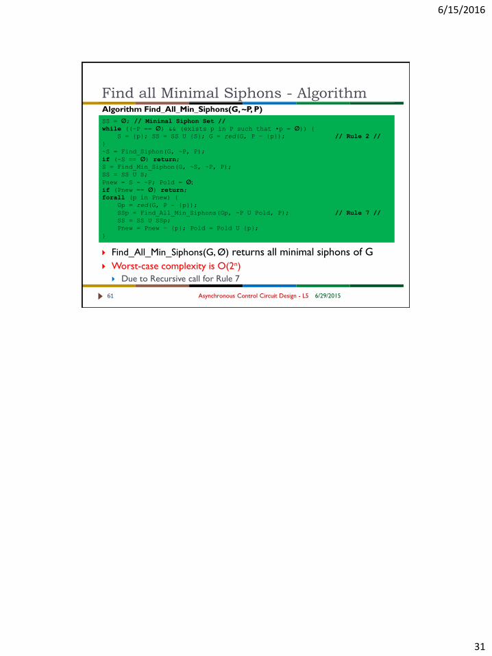
Algorithm Find_All_Min_Siphons(G, ~P, P)
SS = Ø; // Minimal Siphon Set //
while ((~P == Ø) && (exists p in P such that •p = Ø)) {
S = {p}; SS = SS U {S}; G = red(G, P – {p}); // Rule 2 //
}
~S = Find_Siphon(G, ~P, P);
if (~S == Ø) return;
S = Find_Min_Siphon(G, ~S, ~P, P);
SS = SS U S;
Pnew = S - ~P; Pold = Ø;
if (Pnew == Ø) return;
forall (p in Pnew) {
Gp = red(G, P – {p});
SSp = Find_All_Min_Siphons(Gp, ~P U Pold, P); // Rule 7 //
SS = SS U SSp;
Pnew = Pnew – {p}; Pold = Pold U {p};
}
Find all Minimal Siphons - Algorithm
6/29/2015Asynchronous Control Circuit Design - L561
Find_All_Min_Siphons(G, Ø) returns all minimal siphons of G
Worst-case complexity is O(2n)
Due to Recursive call for Rule 7