asynchronous contact mechanics - columbia university
TRANSCRIPT

Asynchronous Contact Mechanics
David Harmon
Columbia University
Etienne Vouga
Columbia University
Breannan Smith
Columbia University
Rasmus Tamstorf
Walt Disney Animation Studios
Eitan Grinspun
Columbia University
Figure 1. A prescribed particle slowly moves through a set of curtains, then impulsively shifts to a very high velocity. The slow and fast phases highlight the
method’s ability to handle smooth resting and sliding with deep stacking, and arbitrarily fast penetration-free movements in which collisions are treated when
(as opposed to well before or after) they occur. The curtains continue to swing for a long time, even as controlled internal dissipation damps high frequencies.
Abstract
We develop a method for reliable simulation of elastica in com-plex contact scenarios. Our focus is on firmly establishingthree parameter-independent guarantees: that simulations of well-posed problems (a) have no interpenetrations, (b) obey causality,momentum- and energy-conservation laws, and (c) complete in fi-nite time. We achieve these guarantees through a novel synthe-sis of asynchronous variational integrators, kinetic data structures,and a discretization of the contact barrier potential by an infinitesum of nested quadratic potentials. In a series of two- and three-dimensional examples, we illustrate that this method more easilyhandles challenging problems involving complex contact geome-tries, sharp features, and sliding during extremely tight contact.
CR Categories: I.3.7 [Computer Graphics]: Three-Dimensional Graphics
and Realism—Animation
Keywords: variational, symplectic, contact, collision, simulation
1 Motivation
Even as computer hardware benefits from Moore’s Law, our abilityto program, debug, and maintain software advances at a humblerpace. This observation shapes our priorities as we develop physi-cal simulation tools for computer graphics. While making choicesthat yield up-front simplicity and blazing performance is importanttoday, we prefer that these choices do not obstruct our long-termgoals of extending functionality and improving realism. Layingaside ad-hoc models in favor of physical approaches might requirea deeper initial investment, but it promises to pay off handsomely inpredictability, controllability, and extensibility. From this vantagepoint, we propose to revisit the long-studied problem of simulatingdeformable objects in complex contact scenarios.
Safety, correctness, progress Robust simulation of complexcontact scenarios is critical to applications spanning graphics (train-ing, virtual worlds, entertainment) and engineering (product design,safety analysis, experimental validation). Challenging scenarios in-volve dynamics with frequent and distributed points of contact, in-teraction with sharp boundaries, resting and sliding contact, andcombinations thereof. Useful resolution of these scenarios requiresconsideration of the fundamental issues of geometric safety, phys-ical correctness, and computational progress, with the respectivemeanings that (a) for well-posed problems the simulation does notenter an invalid (interpenetrating) state, (b) collision response obeysphysical laws of causality and conservation (of mass, momentum,energy, etc.), and (c) the algorithm completes a simulation in finite,preferrably short, time.
An ideal algorithm offers provable guarantees of safety, correct-ness, and progress. A safety guarantee eliminates the need to iteratethrough the animation-design process because of unsightly penetra-tion artifacts; such a guarantee should not fall on an overburdeneduser lapped in tunable parameters. A correctness guarantee is a pre-requisite for physical behavior that is consistent under rediscretiza-tion of space and time. Respect for causality is critical to capturingchain reactions and phenomena such as waves and stacking; dis-crete conservation laws allow for the development of tunable dissi-pation that does not “cross-talk” with parasitic numerical damping.If, however, these two guarantees are not accompanied by guaran-teed progress, the simulation may never complete, no matter howfast or parallel the hardware.
Shortcomings of synchrony Most time integration methods aresynchronous, moving the entire configuration forward in lock-stepfrom one instant in time to the next. Such synchrony is fundamen-tally at odds with safety, correctness, and progress: the first twogoals are assured by attending to collisions in order of causality,which can require arbitrarily small times steps. The number of pos-sible impact events in a single “reasonable” time step can be enor-mous: in their analysis of contact, Cirak and West [2005] present acounting argument and conclude that synchronous “contact simula-tion algorithms cannot attempt to exactly compute the sequence andtiming of all impacts,” as this would preclude reasonable progress.
The graphics community’s prevailing emphasis on progress has mo-tivated many efforts to find, retroactively, a physically plausiblecollision response to a set of collisions that occurred over a preced-ing time interval [Provot 1997; Bridson et al. 2002]. Such methodstypically have adjustable parameters that must be carefully chosen

to balance safety and progress; other methods discard causality infavor of progress [Milenkovic and Schmidl 2001].
The principled, faithful simulation of complex collisions for de-formable objects remains an open, challenging, and important prob-lem.
Asynchrony We propose to place safety and correctness onan equal footing with progress. To overcome the fundamen-tal opposition between these requirements, we turn to asyn-chronous integration, which integrates each geometric element atits own pace, not in lockstep with the entire object. Asynchronyoffers compelling long-term advantages for simulations of de-formable objects in complex contact—advantages that remain un-explored, in particular in terms of safety, correctness, and progress.
0 8 9
02
04
06
08
01
00
Simulated time (seconds)
Pe
rce
nta
ge
of ve
rtic
es
3.29 10-6 3.16 10-4
(larger)(smaller)
2 4 61 3 5 7
time step (log scale)
Figure 2. Asynchrony in the cur-
tain simulation, depicted by the time-
evolving distribution of vertex time
step sizes, enables adaptive alloca-
tion of computational resources in
spacetime.
For scenarios involving sharpboundaries or dispersedpoints of contact, asynchronyrenders non-interpenetrationand momentum conservationtractable. Because elementsadvance at their own pace,those not entangled in col-lisions can proceed at largetime steps. As shown inFigure 2, the median time stepof an asynchronous methodcan be moderate even whentight collisions force someelements to proceed at smalltime steps.
Asynchronous integration As a point of departure we considerasynchronous variational integrators (AVIs) [Lew et al. 2003],which belong to a larger class of integrators that exactly conserveboth momentum and symplecticity (loosely related to areas in phasespace). The well-known Verlet (“leapfrog”) integrator is symplec-tic; such integrators are highly regarded because of their provableapproximate conservation of energy over long spans of simulatedtime. AVIs were previously demonstrated to enjoy these correct-ness properties while simultaneously allowing for efficient treat-ment of spatially non-uniform discretizations; however, a correctcontact model remains unexplored.
Asynchronous collision detection To ensure safety, we requirean equally principled approach to collision detection. This is aheavily studied problem; alas, the many reported successes are spe-cific to the synchronous context, and as a group current methodscan be intractably slow if naıvely applied after each local asyn-chronous step. This motivates our interest in kinetic data structures(KDSs) [Basch et al. 1999]: a KDS algorithm maintains a datastructure governed by formal invariants describing some discrete at-tribute (such as absence of collisions), in response to the continuousmovement of geometric elements. Many existing collision detec-tion methods can be reformulated from a KDS perspective. KDSsseem destined for asynchronous applications, because their focuson fast, minimal, “output-sensitive” data-structure updates makesthem ideally suited for the small, local changes effected by eachAVI step. And yet, while KDSs are the perfect suitor for AVIs withtheir safety complementing AVIs’ correctness, no such matrimonyhas yet been considered.
Contributions These observations motivate our interest in ap-proaching contact mechanics for both graphics and mechanics ap-plications from a new direction. In particular, (a) we formulate acontact model that is safe independent of user parameters; (b) wecorrectly discretize time, using asynchrony to preserve the model’ssafety and to respect causality, and using a symplectic-momentumintegrator to exactly conserve momentum and approximately con-serve energy over long run times. (c) We lay out the basic founda-tions for the union of AVIs with KDSs, making tractable the safe,correct integration of complex contact for highly deformable ob-jects. Finally, we (d) expose a simple model of dissipation andfriction that preserves symmetries of immersion and behaves con-sistently across changes to temporal discretization.
Method in brief Throughout our exposition, we will refer to linenumbers of Algorithm 1, which summarizes the event-driven sim-ulation loop. Rather than keeping the entire configuration synchro-nized in time, each vertex i stores its “most recently seen” positionxi and velocity xi as recorded at time ti. Events, each embody-ing some simple local atomic action, are drawn and processed incausal order (see algorithm LINE 2). The state of all vertices in thestencil of this drawn event must be advanced to the current time(LINES 3–7). When a force event is drawn, we apply impulsesto the local stencil of vertices (see LINE 9 and §3); since the im-pulses affect the vertices’ future trajectories, we must update thecontinuous-time collision-detection data structures (see LINES 11–14 and §5). Some events embody data structure certificate updatesbut do not affect the trajectory (see LINES 15–18 and §5).
1: loop
2: (E,V,h, t)← Q.pop // Pop event E with potential V , time step h,
// and scheduled time t, from time-ordered queue Q
3: ξ := stencil(E) // global indices of the local stencil
4: for i ∈ ξ do
5: xi← xi +(t− ti)xi // advance vertex to current time (see §3)
6: ti← t // update vertex’s clock
7: end for
8: if E is a (external, internal, contact) force event then
9: qξ ← qξ −hM−1ξ
∂V/∂qξ // local impulses, local mass (see §3)
10: Q.push(E,V,h, t +h) // Return the event to the queue, with new time
11: for j ∈i∈ξ⋃
contingent(i) do
12: s← failureTime(E j) // compute new event time (see §5.1)
13: Q.update(E j,s) // reschedule the contingent event (see §5.2)
14: end for
15: else if E is certificate failure then
16: update KDS certificate, reschedule in Q // see §5.1 and §5.3
17: (de)activate penalty forces // see §4
18: end if
19: end loop
2 Related work
Computational Contact Mechanics is a well-studied prob-lem [Wriggers and Laursen 2007; Johnson 2008] of constraint en-forcement: a physical trajectory travels only through the admissibleregion—the subspace of collision-free configurations (see Fig. 3).Framing collision response as an instance of constraint enforcementenables future generalizations of our method to other constraints(e.g., inextensibility enforcement in §7).
To enforce constraints, engineers turn to penalty forces. Asnoted by Wriggers and Panagiotopoulos [1999], analysis beginswith the impulsive penalty force, an infinite spike where bod-ies are in contact and zero elsewhere. The spike is impossi-ble to model with a conservative force, necessitating approxima-

tion with quadratic or higher-order penalty potentials. In deviat-ing from true impulses, penalty potentials permit visible penetra-tion; stiffening the force helps, but it also induces smaller timesteps. On the other hand, a low stiffeness leads to disasterous tun-nelling through the inadmissible region (see Fig. 3). These draw-backs motivate adoption of Lagrange multipliers and unilateralcontact laws [Pfeiffer and Glocker 2000; Eck et al. 2005], whereconstraint-enforcing balance constraint-violating forces. Multi-ple simultaneous contacts induce linear complementarity problems(LCPs) [Wriggers and Laursen 2007], with their attendant com-plexity and numerical pitfalls.
admissible
inadmissible
Figure 3. Trajectories (ar-
rows) must remain in the
admissible (white) region.
Graphics and robotics have embracedthese developments, extending them withan eye to simplicity and efficiency. Ter-zopoulos et al. [1987] used penaltymethods to treat contact between elas-tic bodies. Hahn [1988], Mirtich andCanny [1995] used impulses, view-ing contact as micro-collisions, whileBaraff [1989; 1994], Stewart and Trin-kle [1996] presented LCP treatments formultiple simultaneous contacts with fric-tion. Specifically targeting complex clothcollisions, Bridson et al. [2002] presenta velocity filter that combines the advantages of penalty andimpulsive methods, and relies on a geometric approximationfor difficult impact zones [Provot 1997; Harmon et al. 2008]; ge-ometric approaches are also instrumental in resolving pinch-ing and other challenging configurations [Baraff et al. 2003;Volino and Magnenat-Thalmann 2006; Sifakis et al. 2008]. Re-cently, Guendelman et al. [2003] and Kaufman et al. [2005; 2008]treated complex stacking and friction for rigid bodies. An attemptto directly incorporate these collision algorithms into AVIs facestwo challenges: many methods amortize cost by assuming temporalsynchronization; a straightforward interleaving of contact-responseand symplectic integration algorithms breaks the latter’s good mo-mentum and energy behavior (see §3).
Several works consider asynchronous handling of contact.Lubachevsky [1991] used an event-driven priority-queue algo-rithm to simulate billiard balls, Celes [1998] handled contact be-tween multiple mass-spring bodies, and such approaches extend togranular materials [Poschel and Schwager 2005]. Mirtich [2000]enabled aggressive advancement of rigid body simulations withprovably-correct partial-state rollback to fix missed collisions. De-bunne et al. [2001] considered multirate time integration for simu-lation of visco-elastica. Dequidt et al. [2004] reframed asynchronyfrom an autonomous agent perspective. Thomaszewski et al. [2008]applied AVIs to cloth simulation, using a three-pass approach thataims to efficiently resolve collisions.
What sets our work apart is the focal triad of safety, correctness, andprogress. Methods that prioritize progress by relaxing correctnesscan have downstream costs of simulation setup, feature develop-ment, and artifact resolution. For example, many popular methodsfor cloth simulation justifiably assume a zero coefficient of resti-tution (COR). These assumptions can be so deeply ingrained thatallowing adjustment of CORs is impossible without a major over-haul or painstaking parameter-tuning. As another example, local(“Gauss-Seidel” or “Jacobi”) iterative techniques essentially opti-mize for the case of light collisions, resorting to (unphysical) “fail-safes” when the going gets tough.
In summary, the mechanics literature describes physical models forcontact, but lacks many of the sophisticated algorithms consideredby computer scientists; meanwhile, the trend in graphics has beento start with a fast but approximate solution, and then to chip away
at the unphysical artifacts and the lack of scalability. By contrast,we begin with a more costly, but geometrically safe and physicallyconservative method, and build up efficiency using tools such asasynchrony and persistence.
3 Asynchronous variational integrators
Consider a mechanical system with a time-varying configurationq(t) in the space Q of all configurations; concretely, for a mesh
with vertices x1, . . . ,xn in 3D we represent Q = R3n by a vector
of all the vertices’ Cartesian coordinates. We use a dot to denotedifferentiation in time, so that q(t) is the configurational velocity.Let M be the mass matrix, so that p = Mq is the momentum.
The Verlet integrator evolves a sequence of positions q0,q1,q2 . . .and momenta p0,p1,p2 . . . via the update rules
qk−qk−1 = hM−1pk−1 , pk−pk−1 = hF(qk) , tk− tk−1 = h ,
where h is the time step and F(q) is the force. Thesub/superscripted indices allude to the method’s alias, leapfrog, re-minding us that positions and velocities are staggered in time, with
tk associated to qk, and (tk, tk+1) associated to pk. In effect, Verletfirst updates the position at tk using the constant momentum asso-ciated to the preceding interval (tk−1, tk) (Algorithm LINE 5), andthen impulsively “kicks,” obtaining a new momentum for the fol-lowing interval (tk, tk+1) (Algorithm LINE 9), yielding a piecewiselinear (p.l.) trajectory over the intervals (tk, tk+1). A geometric in-tegrator [Hairer et al. 2002; Kharevych et al. 2006], Verlet tracksconservation laws (e.g., mass, momentum, energy) and adiabaticinvariants (e.g., temperature) over long run times, and offers moreconsistency and qualitatively predictable behavior across a range oftime step sizes.
AVIs naturally extend Verlet. Each force receives an independent,regular (fixed-rate) clock, fixed a priori by stability requirements.While impulses of a force are regularly spaced in time, the super-position of forces yields events irregular in time. As with Verlet,the trajectory is p.l., interrupted by “kicks.” When their clocks arenested—as quarter notes are nested in half notes—AVIs reduce toan instance of multistepping methods [Hairer et al. 2002]. Our de-velopments apply to this family of methods.
For example, Lew et al. [2003] assign an elastic potential to eachmesh element. Irregular meshes have spatially-varying elementshapes and corresponding time step stability restrictions; with AVIseach element advances at its own pace. Since an elemental potentialdepends only on a local mesh nieghborhood, each integration eventis local, affecting the position and velocity of a small number ofstencil vertices. Correspondingly, Algorithm LINE 9 uses the localforces and mass matrix.
To schedule the interrupts to the p.l. trajectory, AVIs use a priorityqueue, conceptually populated with all event times until eternity.In practice it suffices to schedule only the next tick for each clock,since that event can schedule the subsequent tock (LINE 10).
Ensuring correctness A more complete analysis leadingto the geometric and conservation properties of AVIs in-vokes ideas from discrete mechanics and variational integra-tion [Marsden et al. 1998; Lew et al. 2003]. Here we stress a keyoutcome: Lew et al. conjecture that AVIs’ remarkable propertiesare due to its multisymplecticity (a property we further develop ina technical report [Vouga et al. 2009]); the derivation requires eachforce to have a regular (constant-rate, ever-ticking) clock. Play-ing with this clock—accelerating or pausing—is strictly forbidden.Interrupting the p.l. trajectory with other mechanisms (e.g., inter-leaving a velocity filter) breaks multisymplecticity.

We demonstrate the perils of tampering with the clock. A freespring of unit stiffness, rest length, and endpoint masses is placedone unit above a ground plane, in a vertical “pogo stick” orienta-tion, and allowed to bounce repeatedly on the ground under gravity.
0.0 0.5 1.0
0.0 0.5 1.0
Simulated time(billions of seconds)
En
erg
yE
ne
rgy
Conservative
Dissipative
00
35
60
We simulate thrice: with ordi-nary AVIs for gravity, the spring,and contact penalty (red horizon-tal line); as before, but restartingthe contact penalty clock at the in-stant of contact (dark blue slopedline); and with AVIs for gravityand the spring, but resolving col-lisions with a reflective impulseat the contact instant (light bluejagged curve). The time-evolutionof total energy reveals that first ap-proach has no evident energy drift,whereas the second systematicallyinjects energy and the third takesa random walk. Good energy be-havior is equally important for dis-sipative systems. We add a smalldashpot and repeat the experiment.Only the regularly clocked penalty force yields the expected, con-trollable energy dissipation.
In large-scale simulations, we observe that tampering with the clockleads to instabilities and inconsistent behavior across mesh res-olutions. Supporting the observed difficulties, Zhong and Mars-den [1988] prove that symplectic-momentum-energy preservingmethods of regular time step do not exist (except for certainintegrable systems); one cannot hope to interleave an energy-momentum collision integration with a symplectic-momentumforce integration and retain either set of properties.
AVIs and contact To the best of our knowledge, the problemof extending AVIs to handle contact mechanics remains open.The conservation properties of AVIs rely on preservation of themultisymplectic form [Marsden et al. 1998; Marsden et al. 2001],and are easily broken by naıvely incorporating existing contact-resolution methods. A principled treatment must consider a multi-symplectic formulation of contact mechanics, and an asynchronouscomputation of collision detection and response.
4 Discrete penalty layers
Consider a simple penalty method that penalizes proximity betweenbodies. For a given surface thickness η , the gap function
gη (q) = ‖xb−xa‖−η
tracks signed proximity between moving points xa and xb. Wheng < 0, the points are said to be proximate. We can express thecontact (or “interaction”) potential and force in terms of g
V rη (g(q)) =
{
12 rg2 if g≤ 0
0 if g > 0 ,F =
{
−rg∇g if g≤ 0
0 if g > 0 ,
respectively, where r is the contact stiffness. Choosing apenalty stiffness is the most criticized problem of the penaltymethod [Baraff 1989]. For any fixed stiffness r, there exists a suf-ficiently large approach velocity such that the contact potential willbe overcome by the momentum, allowing the configuration to tun-nel illegally through an inadmissible region (see Fig. 3).
The barrier method replaces the above contact potential by a func-tion that grows unbounded as the configuration nears the bound-ary g(q) = 0, eliminating the possibility of tunneling. However,
such a function must also have unbounded second derivative, rul-ing out stable fixed-step time integration for any choice of stepsize [Hairer et al. 2002].
To alleviate these concerns, we propose a construction consistingof an infinite family of nested potentials
Vr(l)η(l)
, l = 1,2, . . . ,
where η(l) is a monotonically decreasing proximity (or “thick-ness”) for the l-th potential, and r(l) is a monotonically increasingpenalty stiffness. For these nested potentials to be a barrier, thecumulative energy of these potentials must diverge as the distancebetween two primitives vanishes:
∑l
r(l)η(l)2→ ∞.
We use r(l) = r(1)l3 and η(l) = η(1)l−1/4 [Vouga et al. 2009],where r(1) and η(1) are a simulation-dependent base stiffness andthickness for the outermost layer.
010
00 x
3
En
erg
y
3
1
2
1
1
Figure 4. Discrete penalty layers.
Potential energy of layer n plotted
against proximity; Inset: total poten-
tial energy contributed by all layers
≤ n. The potential energy diverges
as xa approaches xb, guaranteeing
that constraint enforcement is robust.
We call the region η(n + 1) ≤g(q) ≤ η(n), where exactly nof the potentials are nonzero,the n-th discrete penalty layer(see Fig. 4). The nested poten-tials’ respective maximal stabletime steps form a decaying se-quence, and therefore this con-struction requires an adaptiveor asynchronous time steppingalgorithm. Each interaction po-tential has its own integrationclock, and has the opportunityto apply an impulse when itsclock ticks. The question ishow to time step such an infi-nite sequence.
As we are about to see, the above construction transforms aseemingly intractable problem in Computational Mechanics—establishing a multisymplectic treatment of contact mechanics withguaranteed absence of tunneling—into a challenging but address-able problem in Computer Science: efficient bookkeeping on a con-ceptually infinite set of interaction potentials.
Central observation. During any time interval, while conceptuallythe (infinite number of) clocks continue to tick, and the totality ofthe clock ticks is dense in time, only a finite, sparse set of clockticks apply (non-zero) impulses. In particular, the index of the dis-crete penalty layer indicates the number of active potentials; therest, while conceptually present, do not influence the trajectory, andcan be culled without approximation. What is needed is efficientbookkeeping to track which interaction potentials are active; eachstatus change corresponds to a transition between penalty layers—adiscrete change in state due to motion along a continuous trajectory.This is a problem that KDSs were born to solve.
5 Kinetic Data Structures for AVIs
Guibas [1998] gives an overview of kinetic data structures. Ourculling of inactive forces uses an implementation of kinetic sepa-rating slabs, closely related to those used by Guibas et al. [2001b]in the context of rigid polytopes.

5.1 Kinetic separating slabs
As an illustrative example, consider a single particle falling towarda fixed floor. Conceptually, the clock for the first penalty layer isalways ticking; however, it is active (exerting a nonzero impulse)only when the particle drops below height η(1), say at time t. Wemust “activate the clock,” placing it on the priority queue for ex-plicit consideration, no later than time t. Activating too late intro-duces error (misses impulses), while activating too early is correct,albeit overly conservative (some null events are not culled).
Suppose that calculating t is expensive. A conservative opti-mization uses an η(1)-slab—a line extruded to thickness η(1)—separating the particle from the floor. The separating η(1)-slab serves as a proof, or certificate, that the the particle andfloor are at least η(1) apart. This guarantee remains valid un-til either the floor or the particle enters the slab, at which pointthe certificate fails: we can try to find a new slab, or if do-ing so is costly or impossible, activate the first penalty force.
} η(1)
} η(1)
Figure 5. A separat-
ing slab KDS is cre-
ated as proof of no
contact.
Concretely, simulation begins with iden-tifying an η(1)-slab (see Fig. 5); fromthe initial vertex state, and assuming astraight line trajectory, we compute thetime t when the particle enters the slab(LINE 12), and schedule this certificatefailure event on the priority queue (LINE
13). If t is hard to compute, any ear-lier time tcf
1 < t is correct but conservative.
At time tcf1 , the failure event pops off of the
queue (LINE 2). We check the separation dis-tance; suppose it exceeds η(1). We identifya new η(1)-slab (LINE 16), and schedule a
new failure event, say at time tcf2 (see Fig. 6).
Figure 6. A new sep-
arating slab is sched-
uled.
Suppose that the next event, at time tg < tcf2 ,
corresponds to integration of gravity. Weintegrate the particle position, based on itslast-known state and the elapsed time (LINE
5); we integrate the particle velocity basedon the gravitational force (LINE 9). Fail-ure time tcf
2 was computed assuming a con-
stant velocity, an assumption now broken; tcf2
might no longer be conservative, so the fail-ure event must be rescheduled to guaranteesafety (LINES 11–14).
Figure 7. No effi-
cient slab exists, so a
penalty force is acti-
vated.
The simulation continues in this manner. Asthe particle approaches the floor, the benefitsof culling clock ticks of penalty layer one areeventually outweighed by the increasing fre-quency of η(1)-slab events. Our implemen-tation considers the trade-off to occur whenthe separation distance is below 11
10 η(1); thedecision of how to flag this trade-off affectsperformance but not safety or correctness.
When the use of η(1)-slabs is no longer considered profitable, weactivate the layer-one penalty clock (LINE 17) and forgo η(1)-slabs(see Fig. 7). We cull clock ticks of only deeper layers. We certifyinactivity by identifying an η(2)-slab, computing and processingfailure, reconstruction, and rescheduling as described above.
With the layer-one clock active, we soon encounter a layer-onepenalty force integration event. This event is treated in the samemanner as the gravity event or any force event. Furthermore, this
Event Supporting vertices Stencil vertices
Gravity Entire mesh
Stretching force [Lew et al. 2003] Triangle
Bending force [Grinspun et al. 2003] Hinge
Penalty force (§4) Pair of primitives
Separation slab (§5.1) Pair of primitives
k-DOP overlap (§5.5) Those in k-DOP
Render frame
Table 1. Events and their associated supports and stencils.
event serves as an opportunity to check whether the particle is tran-sitioning to a shallower penalty layer: if (a) the penalty impulse isnull, i.e., separation distance exceeds η(1), and (b) the relative ve-locity is separating rather than approaching, then we de-activate thepenalty force, transitioning to the next-shallower layer, and adjust-ing the certificates accordingly. This lazy approach to deactivationis safe by clause (a) alone; clause (b) aids in efficiency, avoidingrapid toggling of penalty layers.
5.2 Stencils, supports, and scheduling dependencies
With a basic depiction of a KDS in place, we proceed to discussefficiency and optimization, after laying out the requisite terminol-ogy. Consider the execution of an event at its scheduled time. Theset of vertices whose velocities are altered is the stencil of the event.The set of vertices whose trajectory was used to schedule this timeis the support of that event Building on the notions of stencil andsupport, an event depends, or is contingent, on another if the sup-port of the former overlaps the stencil of the latter; vice versa, anevent supports another if the stencil of the former overlaps the sup-port of the latter. Table 1 shows the support and stencils for a set oftypical events.
To our knowledge, KDSs were previously applied only to syn-chronous simulations, where the velocities of all primitives are up-dated at the same instant, i.e., the stencil of the force-integrationevent contains the set of all vertices. By contrast, in an AVI simu-lation, force-integration events typically bear small stencils.
(a) (b)
Figure 8. Directed graphs depicting events (boxes), vertices (dots), and
dependencies (directed edges). Integration events (left green boxes) alter
vertex trajectories, forcing rescheduling of dependent events (right orange
boxes). (a) If an integration event has a large stencil, we store event-event
dependencies. (b) If a vertex belongs to multiple stencil and support rela-
tions, we store event-vertex-event dependencies.
Having executed a supporting event, we must reschedule all depen-dent events before proceeding (Algorithm LINES 11–14). This isa problem of executing partially ordered instructions with depen-dencies, and it is thoroughly studied in the computer systems liter-ature [Korneev and Kiselev 2004].
Our implementation maintains a directed graph, where edges fromevents to vertices and vice versa denote stencil and support rela-tions, respectively. When an event executes, the two-neighborhoodof outgoing edges yields the set of events to reschedule. The graphabstraction reveals that events with large stencils, such as gravity,should cache a list of contingent events, while events with smallstencils should construct the list of contingent events on-the-fly; re-fer to Figs. 8a and 8b, respectively.

5.3 Thinning out certificate rescheduling
Every velocity update requires the rescheduling of dependentevents. This rescheduling tends to be too costly and so frequentthat it becomes intractable; these drawbacks are recognized in theKDS literature [Guibas et al. 2001a; Guibas et al. 2004]. We intro-duce the notion of vague trajectories to safely reduce the frequencyof rescheduling.
Certificates are rescheduled when a support-ing trajectory is altered. Because we are us-ing KDSs specifically in the context of con-tact mechanics, we can bring into play physi-cal insights that would otherwise not be at ourdisposal. As an illustrative example, considerNewton’s apple, which after being tossed intothe air follows a parabolic trajectory beforehitting the ground. We now split the appleand connect the two halves with a stiff spring.When we toss the apple once more, what hap-pens? Since the two halves quickly oscillate against each other,the trajectory of each half has many wiggles—changes in velocity.Even so, the trajectory of the center of mass is exactly parabolicand, ignoring the high-frequency wiggles, the trajectory of eachhalf is “overall” parabolic. Most importantly, unless the half-appleis very close to the floor, the parabola serves as an excellent predic-tor of the collision time with the floor, while the velocity associatedto the rapid oscillations is noisy. This noise is twice detrimental:it impoverishes the collision time estimate, and, worse, it causesfrequent rescheduling.
To harness this insight, we consider trajectories with bounded un-certainty. In place of precise linear trajectories, we consider “tubes”wide enough to encompass the noisy oscillations. On the one hand,this requires us to compute certificate expiration times that are con-servative in the sense that they are valid for any precise trajectorythat fits in the tube. On the other hand, the certificate will remainvalid, despite noisy changes to the future trajectory, or flightplan,so long as the current trajectory remains inside the tube. If thepredicted tube is not too thick, and if the actual trajectory remainsinside the predicted tube for sufficient time, we could potentiallyreap a (safe, correct) dramatic reduction in rescheduling.
We pursue a simple implementation motivated by this idea. Recallour scheduling approach for the simple separating slab KDS. Aftercreating a new certificate (say at time t = t0), we scheduled a certifi-cate failure time by solving for the time at which the particle entersthe slab assuming a constant velocity. Because of this restrictiveassumption, even a small impulse necessitated event rescheduling.
To introduce vagueness, we weaken the assumption to allow for atime-varying velocity. We therefore let the velocity of the particlex(t) = x(t0)+u(t), where u(t) is a time-varying vector of boundedlength ‖u(t)‖ ≤ ε . The relaxed assumption has two implications.First, it is now possible for many impulse events to affect the parti-cle without necessitating a certificate rescheduling, so long as eachimpulse keeps ‖x(t)− x(t0)‖ ≤ ε . Indeed, for ε < |x(t0)|, there isa cone of trajectories that avoid rescheduling. Second, the compu-tation of the failure time must be conservative over all future tra-jectories satisfying the relaxed assumption, i.e., we must computethe earliest possible failure time. For the separating slab, the tra-jectory producing the earliest failure “worst case” failure is the onemaintaining ‖u(t)‖= ε with u(t) in the direction of the slab.
Increasing ε reduces rescheduling frequency, since it widens thecone of covered trajectories; unfortunately, it also increases thefrequency of certificate failures, since the worst-case trajectoryreaches the slab sooner; these two considerations must be balanced.
Fortunately, any choice of ε keeps the system safe—the choice of εcannot alter the actual simulated trajectory.
5.4 Broad phase
Our implementation begins with the simple separating slab KDSdescribed above, modified so that slabs have constant (rather thanzero) normal velocity. We consider this the “narrow phase.”
While formally correct, the simple KDS used on its own will notscale efficiently to large scenes. Various sophisticated KDSs trackproximity, offer better “broad-phase” scaling, and could be easilyadapted to the bookkeeping of the DPL index [Basch et al. 1997;Erickson et al. 1999; Guibas et al. 2001a; Agarwal et al. 2002;Gao et al. 2003; Agarwal et al. 2004; Gao et al. 2005]. We have notimplemented all the available methods, thus rather than advocatingfor one candidate, we dedicate our exposition (recall §5.2–5.3 andsee §5.6 below) to those concepts particular to the synthesis of AVIswith KDSs, independent of the chosen KDS. For completeness webriefly describe our implementation of a broad-phase KDS, thenreturn to cross-cutting concepts.
5.5 Kinetic k-DOP hierarchy
A k-discrete oriented polytope (k-DOP) is a bounding volume (BV)described by k/2 real intervals Si = [αi,βi],1 ≤ i ≤ k/2, each de-scribing an object’s extent (or “support”) along some predeter-mined supporting axis di [Konecny and Zikan 1997]. For k = 6 andorthogonal axes, k-DOPs reduce to axis-aligned bounding boxes(AABBs). For k→ ∞, k-DOPs approximate convex hulls.
Like most BVs, k-DOPs work best in a hierarchy whose leavesbound primitives and progressively coarser levels bound aggre-gates [Klosowski et al. 1998]. In synchronous simulations, a col-lision step updates (“rebuilds”) and traverses (“broad phase detec-tion”) the entire hierarchy; the cost is amortized over the consider-ation of all pairwise collisions in the scene. This economy of scaledoes not immediately carry over to AVIs, where each integrationstep updates only a handful of primitives.
The KDS amortizes not over space but over time: as the positionof primitives continuously evolve, we identify discrete transitionsin execution flow of the broad-phase traversal algorithm. Sucha kinetization of the hierarchy traversal is described in detail byWeller and Zachmann [2006] in the context of AABBs and syn-chronous simulations, but the general idea of incrementally updat-ing a collision-detection tree traversal is known well beyond theKDS literature [Ericson 2004]). In retrospect, the approach seemsto fit most naturally as a component of an asynchronous simulation,yet we are not aware of prior work harnessesing the natural affinityof KDSs and AVIs.
For implementation details, we refer the reader to Weller and Zach-mann’s exposition [2006]. Here we describe only the k-DOP andAVI-specific concepts that the former work did not explore.
Since a hierarchical BV algorithm decides whether to recurse bytesting the overlap of two k-DOPs, the associated kinetic proof usesoverlap and non-overlap certificates; the failure times thus corre-spond to instants at which two k-DOPs become (non-)overlapping.
Consider a certificate guaranteeing non-overlap of k-DOPs a andb. The simplest proof identifies a single axis di with disjoint ex-
tents. This proof is valid during time intervals where Sai ∩ Sb
i = /0,
i.e., αbi −β a
i > 0 or αai −β b
i > 0. Following our didactic example(§5.1), assume that the vertex trajectories are linear in time. Sincea k-DOP contains multiple vertices of differing positions and ve-locities, the upper extent β a
i (t) is convex piecewise linear in time,

where kinks correspond to a new “leader” overtaking the extremal
vertex (see Fig. 9); likewise, αai (t), αb
i (t), β bi (t) are convex p.l..
Therefore, computing the failure time reduces to finding the firstinstant at which a p.l. function becomes negative.
Figure 9. One axis of a
k-DOP bounding 4 ver-
tices over time. The
bounds αi(t) and βi(t)are linear functions. The
dashed lines show the
linear envelope which is
a conservative bound for
all t > 0.
A more ambitious certificate uses the k-DOP’s multiple axes, and the observationthat the failure of one axis need not bringdown the whole certificate. Each axis di
yields a set of time intervals where the aand b are separated; the certificate is validover the union of all positive intervals as-sociated to all k/2 axes, i.e., it fails at theinstant where all k/2 axes have negativep.l. functions.
5.6 Fast certificate scheduling
The Achilles’ heel of KDSs is the fre-quency and cost of rescheduling. We re-duced rescheduling frequency using vaguetrajectories; now we explore reducingrescheduling cost.
Solving for a certificate failuretime requires fast root finding tech-niques [Guibas et al. 2004]. Even whenvertex trajectories are linear in time, the algebraic functionrepresented by the certificate can have non-trivial algebraic com-plexity. We avoid these numerical issues by using only certificateswhose failure times are roots of a univariate p.l. polynomial,requiring identification of the (“piecewise”) segment followed by asubtraction and a division for the (“linear”) solve.
The effort of computing a certificate failure time goes in vain whena supporting event executes in the interlude. The more distant thefailure time, the more likely the wasted effort. Can we avoid precisescheduling without compromising safety or correctness?
The general answer is to quickly compute a safe approxi-mate time guaranteed not to exceed the actual certificate failuretime [Guibas et al. 2001a]. The associated reconfirmation event nolonger implies a certificate failure; instead it reconfirms the currentproof by attempting to find a future reconfirmation time. When areconfirmation event fails to find a safe future time, we can eitherschedule a true failure time, or treat the failed reconfirmation asa (premature) certificate failure. Either approach is safe, but thelatter (our choice) fully eliminates the typically more complex im-plementation of precise failure time computation. We implementedtwo conservative approximations:
Linear envelope on k-DOP extent: A p.l. function f (t) over t ≥ 0
can be bounded from above by a linear function f (t) = f (0)+ mt,with slope m the maximum over the slopes of the pieces of f (seeFig. 9); a bound from below follows similarly. We use this fact tofind conservative (non-)overlap times for k-DOP extents.
Adaptively short-circuit to the most useful k-DOP axes: Not allk-DOP axes are created equal. Depending on the configuration,some excel while others fail in establishing separation. Can we pro-cess only the the useful axes, taking the intersection of their bounds,and thus reducing by a constant factor the O(nd) computation of ex-tremal velocities and positions? We achieve this in two steps: wefirst assume that the k axes are already (nearly) sorted from most-to least-useful, and we progressively improve our bound by incor-porating an additional axis, until an axis fails to improve the bound;in the second step, we improve the sorting (for next time) by at-tempting to incorporate one random unused axis, and promoting
this axis to the front of the list if it did improve the bound. Forsurface meshes, where k-DOPs have high aspect ratios describedby a couple of axes, this approach is very effective. This idea canbe understood in the language of coresets [Agarwal et al. 2005]; wedynamically update the coreset constituency as the system evolves.
6 Dissipative Forces
In using a geometric integrator, our approach exhibits energy near-conservation for long run times. Controlled dissipation, in theform of friction, impact coefficient of restitution, or viscous damp-ing of high-frequency modes, is often desired in practical simula-tions. Our emphasis here is not on advanced models of dissipa-tion, rather on basic ideas for incorporating controlled dissipationinto our framework without compromising safety, correctness, andprogress.
We ask that the limiting behavior as two events are brought to co-incide should be continuous, i.e., unique and independent of howthis limit is approached. Simultaneous events must yield an order-independent outcome. If a perturbation to the problem setup (e.g.,time step size, initial vertex position) or a numerical error perturbsthe order of nearly contemporaneous events, reordering continuitykeeps the trajectory predictable.
Sufficient condition. If forces depend on positions, past andpresent, but not on momenta, then the trajectory is independent ofthe processing order of simultaneous events. Proof: an event out-come affects only future positions; a computation based on past andpresent positions is unaffected by outcomes of simultaneous events.
Conservative forces trivially satisfy this condition. However, sincethe most straightforward implementation of dissipation computesmomenta-dependent quantities, it fails to meet our sufficient condi-tions, and generally leads to order-dependent outcomes.
Fortunately, a simple solution is at hand. Where a force formu-
lation calls for momentum, we use the Verlet identity pk−1 =M(qk − qk−1)/h, a finite difference of past and present positions.To ensure a well-behaved, regular temporal discretization, we con-sider only the positions associated to the dissipative force’s clock.This corresponds to the average momentum in the interval be-tween dissipative events, which, because of the interruptions in-duced by other asynchronous clocks, will generally not correspondto the momentum immediately preceding the dissipative event.All of this is illustrated in the adjacent fig-ure where the red trajectory shows whatis being used for the computation of thedissipative force, while the green trajec-tory includes updates from all events. Weinvoke this concept in discretizing severaldissipative forces.
6.1 Viscous damping
Consider an elastic spring connecting two vertices i and j. Viscousdamping acts to slow the rate at which the spring changes length.We create a new clock (we could also ride on the elastic clock,stability permitting) and compute a viscous force
Fk,i = b(lk− lk−1)ek/lk =−Fk, j , ek = qk, j−qk,i , lk = ‖ek‖ ,
where b is the damping coefficient, qk,i is the position of the i-thvertex, and the vector ek and length lk are local; a subscript (i, j) isimplied. We cache lk−1 so that we can use its value at time tk.
In the case of a single spring, the approach reduces to explicit Verletintegration of the viscous force, with its attendant time step restric-tion. Bridson et al. [2003] advocate a semi-implicit integration of
the viscous force. Such an approach might also be adopted in placeof the one presented above, trading order independent processingof simultaneous events for larger viscous force time steps.
Most of our simulations incorporate some viscous internal (stretch-ing and bending) damping. The curtains (see Fig. 1 and video)illustrate the benefit of starting from a conservative foundation. Us-ing only internal damping, high-frequency vibrations introduced bythe prescribed particle are quickly damped out, while the curtains’graceful swinging continues; using a non-geometric integrator suchas backward Euler or BDF2 [Ascher and Petzold 1998], the swing-ing motion would also be damped.
6.2 Coefficient of restitution
The coefficient of restitution eCOR is a “melting pot” approxi-mation, accounting for various unresolved micro-level phenom-ena [Brilliantov and Poschel 2004; Schwager and Poschel 2007]including viscosity and plasticity. To model plastic work,we replace the nested penalty potentials with biphasic poten-tials [Choi and Ko 2005]
V rη (g(q)) =
{
12 rcg(q)2 g≤ 0
0 g≥ 0,
where c is eCOR if the primitives are separating, 1 otherwise.The penalty layers exert their full force during compression, thenweaken according to the coefficient of restitution during decom-pression. We could (but did not) further extend this model to ac-count for viscous damping during impact, measuring strain rate by(some monotonic function of) the change in the gap function g(q).
While simple, our appraoch has a drawback in the inelastic limiteCOR = 0: the penalty impulses can leave as residue a small sep-arating relative velocity. The magnitude of this velocity is at mostr(l)η(l)h, where h is the layer’s time step, so it can be limited bychoosing a small enough r(l) or h.
0 5 10 15 20Simulated time (seconds)
En
erg
y0
18
0
0.0
0.80.70.50.2
1.0
0.9
The long-term good en-ergy behavior accompany-ing our use of a symplectic-momentum integrator trans-lates into predictable, con-trollable energy dissipationwhen a non-unit coefficientof restitution is used in asimulation. To test the en-ergy behavior for a varietyof coefficients of restitution,we simulated a box of 900 particles with random initial velocities.The incident figure shows the energy of the system as a functionof time for multiple values of eCOR; in all cases energy decayssmoothly and predictably.
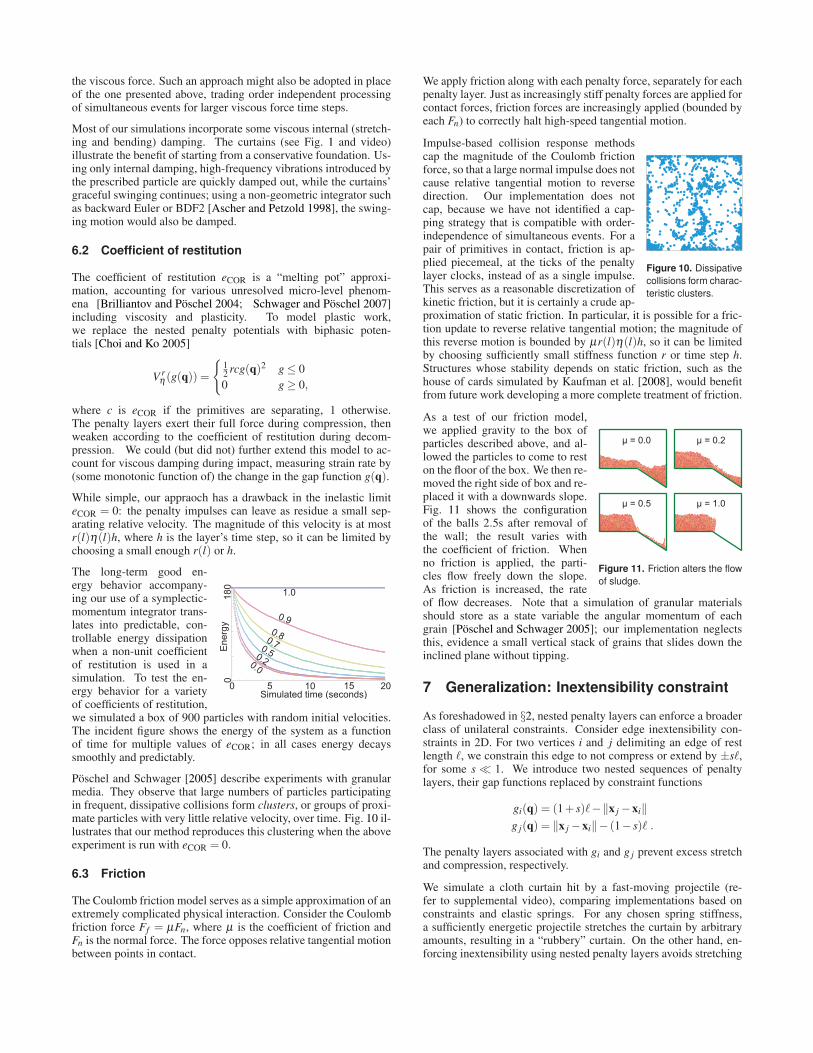
Poschel and Schwager [2005] describe experiments with granularmedia. They observe that large numbers of particles participatingin frequent, dissipative collisions form clusters, or groups of proxi-mate particles with very little relative velocity, over time. Fig. 10 il-lustrates that our method reproduces this clustering when the aboveexperiment is run with eCOR = 0.
6.3 Friction
The Coulomb friction model serves as a simple approximation of anextremely complicated physical interaction. Consider the Coulombfriction force Ff = µFn, where µ is the coefficient of friction andFn is the normal force. The force opposes relative tangential motionbetween points in contact.
We apply friction along with each penalty force, separately for eachpenalty layer. Just as increasingly stiff penalty forces are applied forcontact forces, friction forces are increasingly applied (bounded byeach Fn) to correctly halt high-speed tangential motion.
Figure 10. Dissipative
collisions form charac-
teristic clusters.
Impulse-based collision response methodscap the magnitude of the Coulomb frictionforce, so that a large normal impulse does notcause relative tangential motion to reversedirection. Our implementation does notcap, because we have not identified a cap-ping strategy that is compatible with order-independence of simultaneous events. For apair of primitives in contact, friction is ap-plied piecemeal, at the ticks of the penaltylayer clocks, instead of as a single impulse.This serves as a reasonable discretization ofkinetic friction, but it is certainly a crude ap-proximation of static friction. In particular, it is possible for a fric-tion update to reverse relative tangential motion; the magnitude ofthis reverse motion is bounded by µr(l)η(l)h, so it can be limitedby choosing sufficiently small stiffness function r or time step h.Structures whose stability depends on static friction, such as thehouse of cards simulated by Kaufman et al. [2008], would benefitfrom future work developing a more complete treatment of friction.
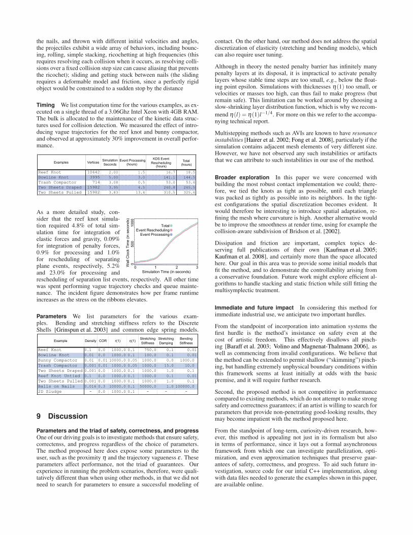
µ = 0.0 µ = 0.2
µ = 0.5 µ = 1.0
Figure 11. Friction alters the flow
of sludge.
As a test of our friction model,we applied gravity to the box ofparticles described above, and al-lowed the particles to come to reston the floor of the box. We then re-moved the right side of box and re-placed it with a downwards slope.Fig. 11 shows the configurationof the balls 2.5s after removal ofthe wall; the result varies withthe coefficient of friction. Whenno friction is applied, the parti-cles flow freely down the slope.As friction is increased, the rateof flow decreases. Note that a simulation of granular materialsshould store as a state variable the angular momentum of eachgrain [Poschel and Schwager 2005]; our implementation neglectsthis, evidence a small vertical stack of grains that slides down theinclined plane without tipping.
7 Generalization: Inextensibility constraint
As foreshadowed in §2, nested penalty layers can enforce a broaderclass of unilateral constraints. Consider edge inextensibility con-straints in 2D. For two vertices i and j delimiting an edge of restlength ℓ, we constrain this edge to not compress or extend by ±sℓ,for some s≪ 1. We introduce two nested sequences of penaltylayers, their gap functions replaced by constraint functions
gi(q) = (1+ s)ℓ−‖x j−xi‖
g j(q) = ‖x j−xi‖− (1− s)ℓ .
The penalty layers associated with gi and g j prevent excess stretchand compression, respectively.
We simulate a cloth curtain hit by a fast-moving projectile (re-fer to supplemental video), comparing implementations based onconstraints and elastic springs. For any chosen spring stiffness,a sufficiently energetic projectile stretches the curtain by arbitraryamounts, resulting in a “rubbery” curtain. On the other hand, en-forcing inextensibility using nested penalty layers avoids stretching

Figure 12. Simulated tying of ribbons into a reef knot.
Figure 13. A closeup of the reef knot.
no matter the projectile’s velocity. Implementation of the inextensi-bility constraint for 3D triangle meshes would require a constraintformulation that does not lock bending modes, such as that pro-posed by English and Bridson [2008].
8 Results
In §3 and §6, we described simple experiments and empirical mea-surements supporting the guaranteed safety and good energy be-havior of the proposed contact algorithm, for both conservative anddissipative contact. We turn our attention to challenging problemsinvolving complex contact geometries, sharp features, and slidingduring extremely tight contact.
Knots We simulate the tying of ribbons into reef and bowlineknots (see Figs. 12 and 14, respectively). The ribbons are mod-eled as a loose knot, assigned a material with stiff stretching andweak bending, and their ends are pulled by a prescribed force; thebowline knot requires also the prescription of fixed vertices behindthe cylinder where a finger normally holds the material in place.The final configuration is faithful to the shape of actual “boyscoutmanual” knots.
This example demonstrates the strength of asynchrony in allocat-ing resources to loci of tight contact. As the knot tightens, progres-sively finer time steps are used for the tightest areas of contact.If instead of prescribing reasonable forces we directly prescribean outward motion of the two ends of the ribbon, the simulationsexecute to the point where the mesh resolution becomes the lim-iting reagent, i.e., a tighter knot cannot be tied without splitting
Figure 14. Simulated tying of a ribbon into a bowline knot.
Figure 15. Virtual trash compactor and assorted virtual trash.
Figure 16. Experiments with a bed of nails highlight the method’s ability to
deal with sharp boundaries, isolated points of contact, sliver triangles, and
localized points of high pressure between two nearly incident surfaces.
triangles; past this point, the computation slows as penalty interac-tions burrow to deeper layers and the mean time step decays. Thishighlights both a feature and a potential artistic objection to themethod: when presented with an impossible or nearly-impossiblesituation (non-stretchy ribbon with prescribed diametrically oppos-ing displacements at its ends) the method’s safety guarantee inducesZeno’s Paradox.
0 1.25
02
04
06
08
01
00
Simulated time (seconds)
Pe
rce
nta
ge
of ve
rtic
es
3.7 10-7 1.0 10-4
time step
(log scale) (larger)(smaller)
0.50 1.000.25 0.75
Trash compactor Weplace triangle meshesof varying complexityinto a virtual trashcompactor consisting ofa floor and four walls,and then prescribethe inward motion ofopposing walls (seeFig. 15 and incidentimage). The method isable to simulate the approach of the walls without ever allowingfor seen or unseen penetrations. As with the knots, the overallrate of progress decays as the simulation approaches a limitingconfiguration.
Bed of nails We crafted a prob-lem to test the handling of isolatedpoint contacts and sharp bound-aries. Four sliver triangles are as-sembled into a nail, and many suchnails are placed point-up on a flatbed. We drape two stacked fabricsover the bed of nails (see Fig. 16),and observe that the simulated trajectory is both realistic and free ofpenetrations, oscillations, or any other artifacts typically associatedto contact discontinuities. Next, we prescribe the motion of one endof the fabric, tugging on the draped configuration to demonstratesliding over sharp features.
We extend the bed of nails into a landing pad for various coarsely-meshed projectiles. Variably-sized to barely fit or not fit between
the nails, and thrown with different initial velocities and angles,the projectiles exhibit a wide array of behaviors, including bounc-ing, rolling, simple stacking, ricochetting at high frequencies (thisrequires resolving each collision when it occurs, as resolving colli-sions over a fixed collision step size can cause aliasing that preventsthe ricochet); sliding and getting stuck between nails (the slidingrequires a deformable model and friction, since a perfectly rigidobject would be constrained to a sudden stop by the distance
Timing We list computation time for the various examples, as ex-ecuted on a single thread of a 3.06Ghz Intel Xeon with 4GB RAM.The bulk is allocated to the maintenance of the kinetic data struc-tures used for collision detection. We measured the effect of intro-ducing vague trajectories for the reef knot and bunny compactor,and observed at approximately 30% improvement in overall perfor-mance.
Simulation
Seconds
Event ProcessingKDS Event
ReschedulingTotal
Reef Knot 10642 2.00 1.5 16.7 18.5
Bowline Knot 3995 5.00 3.0 141.1 144.5
Trash Compactor 714 3.08 0.5 53.0 53.6
Two Sheets Draped 15982 3.95 4.5 260.8 265.5
Two Sheets Pulled 15982 3.83 13.6 310.5 325.6
Examples Vertices(hours)
(hours)(hours)
0 5
00
10
00
3Wa
ll C
lock T
ime
(in
se
co
nd
s)
Simulation Time (in seconds)
Total
Event ProcessingEvent Rescheduling
2 1 0
As a more detailed study, con-sider that the reef knot simula-tion required 4.8% of total sim-ulation time for integration ofelastic forces and gravity, 0.09%for integration of penalty forces,0.9% for processing and 1.0%for rescheduling of separatingplane events, respectively, 5.2%and 23.0% for processing andrescheduling of separation list events, respectively. All other timewas spent performing vague trajectory checks and queue mainte-nance. The incident figure demonstrates how per frame runtimeincreases as the stress on the ribbons elevates.
Parameters We list parameters for the various exam-ples. Bending and stretching stiffness refers to the DiscreteShells [Grinspun et al. 2003] and common edge spring models.
Example Density COR r(1) (1)Stretching
Stiffness
Stretching
Damping
Bending
Stiffness
Reef Knot 0.1 0.0 1000.0 0.1 750.0 0.1 0.01
Bowline Knot 0.01 0.0 1000.0 0.1 100.0 0.1 0.01
Bunny Compactor 0.01 0.01 10000.0 0.05 1000.0 0.0 1000.0
Trash Compactor 0.001 0.01 1000.0 0.05 1000.0 15.0 10.0
Two Sheets Draped 0.001 0.0 1000.0 0.1 1000.0 1.0 0.1
Reef Knot Untied 0.1 0.0 1000.0 0.1 1000.0 0.1 0.01
Two Sheets Pulled 0.001 0.0 1000.0 0.1 1000.0 1.0 0.1
Balls on Nails 0.016 0.3 10000.0 0.1 50000.0 1.0 100000.0
2D Sludge - 0.0 1000.0 0.1 - - -
9 Discussion
Parameters and the triad of safety, correctness, and progress
One of our driving goals is to investigate methods that ensure safety,correctenss, and progress regardless of the choice of parameters.The method proposed here does expose some parameters to theuser, such as the proximity η and the trajectory vagueness ε . Theseparameters affect performance, not the triad of guarantees. Ourexperience in running the problem scenarios, therefore, were quali-tatively different than when using other methods, in that we did notneed to search for parameters to ensure a successful modeling of
contact. On the other hand, our method does not address the spatialdiscretization of elasticity (stretching and bending models), whichcan also require user tuning.
Although in theory the nested penalty barrier has infinitely manypenalty layers at its disposal, it is impractical to activate penaltylayers whose stable time steps are too small, e.g., below the float-ing point epsilon. Simulations with thicknesses η(1) too small, orvelocities or masses too high, can thus fail to make progress (butremain safe). This limitation can be worked around by choosing aslow-shrinking layer distribution function, which is why we recom-
mend η(l) = η(1)l−1/4. For more on this we refer to the accompa-nying technical report.
Multistepping methods such as AVIs are known to have resonanceinstabilities [Hairer et al. 2002; Fong et al. 2008], particularly if thesimulation contains adjacent mesh elements of very different size.However, we have not observed any such instabilities or artifactsthat we can attribute to such instabilities in our use of the method.
Broader exploration In this paper we were concerned withbuilding the most robust contact implementation we could; there-fore, we tied the knots as tight as possible, until each trianglewas packed as tightly as possible into its neighbors. In the tight-est configurations the spatial discretization becomes evident. Itwould therefore be interesting to introduce spatial adaptation, re-fining the mesh where curvature is high. Another alternative wouldbe to improve the smoothness at render time, using for example thecollision-aware subdivision of Bridson et al. [2002].
Dissipation and friction are important, complex topics de-serving full publications of their own [Kaufman et al. 2005;Kaufman et al. 2008], and certainly more than the space allocatedhere. Our goal in this area was to provide some initial models thatfit the method, and to demonstrate the controllability arising froma conservative foundation. Future work might explore efficient al-gorithms to handle stacking and static friction while still fitting themultisymplectic treatment.
Immediate and future impact In considering this method forimmediate industrial use, we anticipate two important hurdles.
From the standpoint of incorporation into animation systems thefirst hurdle is the method’s insistance on safety even at thecost of artistic freedom. This effectively disallows all pinch-ing [Baraff et al. 2003; Volino and Magnenat-Thalmann 2006], aswell as commencing from invalid configurations. We believe thatthe method can be extended to permit shallow (“skimming”) pinch-ing, but handling extremely unphysical boundary conditions withinthis framework seems at least initially at odds with the basicpremise, and it will require further research.
Second, the proposed method is not competitive in performancecompared to existing methods, which do not attempt to make strongsafety and correctness guarantees; if an artist is willing to search forparameters that provide non-penetrating good-looking results, theymay become impatient with the method proposed here.
From the standpoint of long-term, curiosity-driven research, how-ever, this method is appealing not just in its formalism but alsoin terms of performance, since it lays out a formal asynchronousframework from which one can investigate parallelization, opti-mization, and even approximation techniques that preserve guar-antees of safety, correctness, and progress. To aid such future in-vestigation, source code for our intial C++ implementation, alongwith data files needed to generate the examples shown in this paper,are available online.

Acknowledgements We thank David Mooy for modeling theknots, and Igor Boshoer, Matt Kushner, Kori Valz for lighting andrendering. We are grateful for the valuable feedback provided byMiklos Bergou, Rony Goldenthal, Bernhard Thomaszewski, MaxWardetzky, and the anonymous reviewers. This work was supportedin part by the NSF (MSPA Award No. IIS-05-28402, CSR AwardNo. CNS-06-14770, CAREER Award No. CCF-06-43268) and theAmazon Elastic Compute Cloud. The Columbia authors are sup-ported in part by generous gifts from Adobe, ATI, Autodesk, mentalimages, NVIDIA, the Walt Disney Company, and Weta Digital.
References
AGARWAL, P., BASCH, J., GUIBAS, L. J., HERSHBERGER, J.,AND ZHANG, L. 2002. Deformable free space tilings for kineticcollision detection. Intl. J. Robotics Research 21, 179–197.
AGARWAL, P., GUIBAS, L., NGUYEN, A., RUSSEL, D., AND
ZHANG, L. 2004. Collision detection for deforming neck-laces. Computational Geometry: Theory and Applications 28,137–163.
AGARWAL, P. K., HAR-PELED, S., AND VARADARAJAN, K. R.2005. Geometric approximation via coresets. In Combinato-rial and Computational Geometry, J. E. Goodman, J. Pach, andE. Welzl, Eds. Cambridge University Press, New York, 1–30.
ASCHER, U. M., AND PETZOLD, L. R. 1998. Computer meth-ods for ordinary differential equations and differential-algebraicequations. Society for Industrial and Applied Mathematics,Philadelphia.
BARAFF, D., WITKIN, A., AND KASS, M. 2003. Untanglingcloth. ACM Trans. Graph. 22, 3, 862–870.
BARAFF, D. 1989. Analytical methods for dynamic simulationof non-penetrating rigid bodies. In SIGGRAPH ’89: Proceed-ings of the 16th annual conference on Computer graphics andinteractive techniques, ACM, New York, NY, USA, 223–232.
BARAFF, D. 1994. Fast contact force computation for nonpene-trating rigid bodies. In SIGGRAPH ’94, 23–34.
BASCH, J., GUIBAS, L. J., AND ZHANG, L. 1997. Proximityproblems on moving points. In Proc. 13th Annu. ACM Sympos.Comput. Geom., 344–351.
BASCH, J., GUIBAS, L. J., AND HERSHBERGER, J. 1999. Datastructures for mobile data. Journal of Algorithms 31, 1–28.
BRIDSON, R., FEDKIW, R., AND ANDERSON, J. 2002. Robusttreatment of collisions, contact and friction for cloth animation.In SIGGRAPH ’02, 594–603.
BRIDSON, R., MARINO, S., AND FEDKIW, R. 2003. Simulationof clothing with folds and wrinkles. In SCA ’03, 28–36.
BRILLIANTOV, N. V., AND POSCHEL, T. 2004. Kinetic Theory ofGranular Gases. Oxford University Press, USA.
CELES, W. 1998. Efficient asynchronous evolution of physicalsimulations. In SIBGRAPI ’98: Proceedings of the InternationalSymposium on Computer Graphics, Image Processing, and Vi-sion, IEEE Computer Society, Washington, DC, USA, 224.
CHOI, K.-J., AND KO, H.-S. 2005. Stable but responsive cloth. InSIGGRAPH ’05: ACM SIGGRAPH 2005 Courses, ACM, NewYork, NY, USA, 1.
CIRAK, F., AND WEST, M. 2005. Decomposition-based contactresponse (DCR) for explicit finite element dynamics. Int’l Jour-nal for Numerical Methods in Engineering 64, 8, 1078–1110.
DEBUNNE, G., DESBRUN, M., CANI, M.-P., AND BARR, A. H.2001. Dynamic real-time deformations using space & time adap-tive sampling. In SIGGRAPH ’01: Proceedings of the 28thannual conference on Computer graphics and interactive tech-niques, ACM, New York, NY, USA, 31–36.
DEQUIDT, J., GRISONI, L., AND CHAILLOU, C. 2004. Asyn-chronous interactive physical simulation. Tech. Rep. RR-5338,INRIA.
ECK, C., JANUSEK, J., AND KRBEC, M. 2005. Unilateral contactproblems: variational methods and existence theorems. Chap-man and Hall/CRC Press, Boca Raton.
ENGLISH, E., AND BRIDSON, R. 2008. Animating developablesurfaces using nonconforming elements. In SIGGRAPH ’08:ACM SIGGRAPH 2008 papers, ACM, New York, NY, USA, 1–5.
ERICKSON, J., GUIBAS, L. J., STOLFI, J., AND ZHANG, L. 1999.Separation-sensitive collision detection for convex objects. InProc. 10th ACM-SIAM Symp. Discrete Algorithms, 102–111.
ERICSON, C. 2004. Real-Time Collision Detection (The MorganKaufmann Series in Interactive 3D Technology). Morgan Kauf-mann, December.
FONG, W., DARVE, E., AND LEW, A. 2008. Stability of asyn-chronous variational integrators. J. Comput. Phys. 227, 18,8367–8394.
GAO, J., GUIBAS, L., HERSHBERGER, J., ZHANG, L., AND ZHU,A. 2003. Discrete mobile centers. Discrete and ComputationalGeometry 30, 1, 45–65.
GAO, J., GUIBAS, L. J., AND NGUYEN, A. 2005. Distributedproximity maintenance in ad hoc mobile network. In IEEE Inter-national Conference on Distributed Computing in Sensor System(DCOSS’05), 4–19.
GRINSPUN, E., HIRANI, A., DESBRUN, M., AND SCHRODER,P. 2003. Discrete Shells. In ACM SIGGRAPH / EurographicsSymposium on Computer Animation, 62–67.
GUENDELMAN, E., BRIDSON, R., AND FEDKIW, R. 2003. Non-convex rigid bodies with stacking. In SIGGRAPH ’03: ACMSIGGRAPH 2003 Papers, ACM, New York, NY, USA, 871–878.
GUIBAS, L., XIE, F., AND ZHANG, L. 2001. Kinetic collisiondetection: Algorithms and experiments. In Proceedings of theInternational Conference on Robotics and Automation, 2903–2910.
GUIBAS, L. J., XIE, F., AND ZHANG, L. 2001. Kinetic collisiondetection: Algorithms and experiments. In ICRA, 2903–2910.
GUIBAS, L., KARAVELES, M., AND RUSSEL, D. 2004. A com-putational framework for handling motion. In Proceedings ofteh Sixth Workshop on Algorithm Engineering and Experiments,129–141.
GUIBAS, L. J. 1998. Kinetic data structures — a state of the artreport. In Proc. 3rd Workshop on Algorithmic Foundations ofRobotics (WAFR), 191–209.
HAHN, J. K. 1988. Realistic animation of rigid bodies. In SIG-GRAPH ’88: Proceedings of the 15th annual conference onComputer graphics and interactive techniques, ACM, New York,NY, USA, 299–308.
HAIRER, E., LUBICH, C., AND WANNER, G. 2002. Geomet-ric Numerical Integration: Structure-preserving Algorithms forOrdinary Differential Equations. Springer.

HARMON, D., VOUGA, E., TAMSTORF, R., AND GRINSPUN,E. 2008. Robust Treatment of Simultaneous Collisions. SIG-GRAPH ( ACM Transactions on Graphics) 27, 3, 1–4.
JOHNSON, K. L. 2008. Contact mechanics. Cambridge UniversityPress.
KAUFMAN, D. M., EDMUNDS, T., AND PAI, D. K. 2005. Fastfrictional dynamics for rigid bodies. In SIGGRAPH ’05, 946–956.
KAUFMAN, D. M., SUEDA, S., JAMES, D. L., AND PAI, D. K.2008. Staggered projections for frictional contact in multibodysystems. In SIGGRAPH Asia ’08: ACM SIGGRAPH Asia 2008papers, ACM, New York, NY, USA, 1–11.
KHAREVYCH, L., YANG, W., TONG, Y., KANSO, E., MARS-DEN, J. E., SCHRODER, P., AND DESBRUN, M. 2006. Geo-metric, variational integrators for computer animation. In SCA’06: Proceedings of the 2006 ACM SIGGRAPH/Eurographicssymposium on Computer animation, Eurographics Association,Aire-la-Ville, Switzerland, Switzerland, 43–51.
KLOSOWSKI, J. T., HELD, M., MITCHELL, J. S. B., SOWIZRAL,H., AND ZIKAN, K. 1998. Efficient collision detection usingbounding volume hierarchies of k-dops. IEEE Transactions onVisualization and Computer Graphics 4, 1, 21–36.
KONECNY, P., AND ZIKAN, K. 1997. Lower Bound of Distancein 3D. In Proceedings of WSCG 1997, vol. 3, 640–649.
KORNEEV, V., AND KISELEV, A. 2004. Modern Microprocessors.Charles River Media.
LEW, A., MARSDEN, J. E., ORTIZ, M., AND WEST, M. 2003.Asynchronous variational integrators. Archive for Rational Me-chanics And Analysis 167, 85–146.
LUBACHEVSKY, B. 1991. How to simulate billiards and similarsystems. Journal of Computational Physics 94, 2 (June), 255–283.
MARSDEN, J., PATRICK, G., AND SHKOLLER, S. 1998. Mul-tisymplectic Geometry, Variational Integrators, and NonlinearPDEs. Communications in Mathematical Physics 199, 2, 351–395.
MARSDEN, J., PEKARSKY, S., SHKOLLER, S., AND WEST, M.2001. Variational methods, multisymplectic geometry and con-tiunuum mechanics. Journal of Geometry and Physics 38, 3–4(June), 253–284.
MILENKOVIC, V. J., AND SCHMIDL, H. 2001. Optimization-based animation. In SIGGRAPH ’01: Proceedings of the 28thannual conference on Computer graphics and interactive tech-niques, ACM, New York, NY, USA, 37–46.
MIRTICH, B., AND CANNY, J. 1995. Impulse-based dynamic sim-ulation. In WAFR: Proceedings of the workshop on Algorithmicfoundations of robotics, A. K. Peters, Ltd., Natick, MA, USA,407–418.
MIRTICH, B. 2000. Timewarp rigid body simulation. InSIGGRAPH ’00: Proceedings of the 27th annual confer-ence on Computer graphics and interactive techniques, ACMPress/Addison-Wesley Publishing Co., New York, NY, USA,193–200.
PFEIFFER, F., AND GLOCKER, C., Eds. 2000. Multibody Dy-namics With Unilateral Contacts. SpringerWienNewYork, ch. 2,69–146.
POSCHEL, T., AND SCHWAGER, T. 2005. Computational Granu-lar Dynamics: Models and Algorithms. Springer.
PROVOT, X. 1997. Collision and self-collision handling in clothmodel dedicated to design garments. In Computer Animationand Simulation ’97, Springer Verlag, Wien, 177–189.
SCHWAGER, T., AND POSCHEL, T. 2007. Coefficient of restitu-tion and linear dashpot model revisited. Granular Matter 9, 6(November), 465–469.
SIFAKIS, E., MARINO, S., AND TERAN, J. 2008. Globally cou-pled collision handling using volume preserving impulses. In2008 ACM SIGGRAPH / Eurographics Symposium on ComputerAnimation, 147–154.
TERZOPOULOS, D., PLATT, J., BARR, A., AND FLEISCHER, K.1987. Elastically deformable models. In SIGGRAPH ’87: Pro-ceedings of the 14th annual conference on Computer graphicsand interactive techniques, ACM, New York, NY, USA, 205–214.
THOMASZEWSKI, B., PABST, S., AND STRASSER, W. 2008.Asynchronous cloth simulation. In Computer Graphics Inter-national.
TRINKLE, D. S. J. 1996. An implicit time-stepping scheme forrigid body dynamics with inelastic collisions and coulomb fric-tion. Intl. Journal for Numerical Methods in Engineering 39,2673–2691.
VOLINO, P., AND MAGNENAT-THALMANN, N. 2006. Resolvingsurface collisions through intersection contour minimization. InSIGGRAPH ’06: ACM SIGGRAPH 2006 Papers, ACM, NewYork, NY, USA, 1154–1159.
VOUGA, E., HARMON, D., TAMSTORF, R., AND GRINSPUN, E.2009. Discrete penalty layers admit multisymplectic integration.Tech. rep., Columbia University.
WELLER, R., AND ZACHMANN, G. 2006. Kinetic separationlists for continuous collision detection of deformable objects. InThird Workshop in Virtual Reality Interactions and Physical Sim-ulation (Vriphys).
WRIGGERS, P., AND LAURSEN, T. A. 2007. Computationalcontact mechanics, vol. no. 498 of CISM courses and lectures.Springer, Wien.
WRIGGERS, P., AND PANAGIOTOPOULOS, P., Eds. 1999. New De-velopments in Contact Problems. SpringerWienNewYork, ch. 1,1–54.
ZHONG, G., AND MARSDEN, J. E. 1988. Lie-Poisson Hamilton-Jacobi theory and Lie-Poisson integrators. Physics Letters A 133(Nov.), 134–139.