agricultural science i agricultural mechanics i common ... · agricultural mechanics unit for...
TRANSCRIPT
Ag Science I – Ag Mechanics I – Common Hand Tools Common Hand Tools for Woodworking • Page 1 of 11
Course Agricultural Science I
Unit Agricultural Mechanics I
Subunit Common Hand Tools
Lesson Common Hand Tools for Woodworking
Estimated Time 90 Minutes or 2 50-minute blocks Student Outcome
Identify common hand tools used in woodworking. Learning Objectives
1. Identify basic procedures for shop safety. 2. Identify some common measurement tools. 3. Identify some common hand tools for cutting wood. 4. Identify hand tools used for smoothing and shaping wood. 5. Identify hand tools used for drilling and boring. 6. Identify hand tools and materials used for fastening.
Grade Level Expectations
Resources, Supplies & Equipment, and Supplemental Information
Resources 1. PowerPoint Slides
PPt 1 - Basic Procedures for Shop Safety PPt 2 - Common Measurement Tools PPt 3 - Types of Handsaws PPt 4 - Planes/Cutting a Chamfer PPt 5 - Chisel/Cutting a Dado PPt 6 - Files/Using a File PPt 7 - Drilling and Boring Tools PPt 8 - Fasteners
2. Activity Sheet
AS 1 – Identifying Common Woodworking Hand Tools 3. Agricultural Mechanics Unit for Agricultural Science I (Student Reference). University of
Missouri-Columbia: Instructional Materials Laboratory, 2002. 4. Curriculum Enhancement for Agricultural Mechanics Unit for Agricultural Science I, “Unit I -
Common Hand Tools.” University of Missouri-Columbia: Instructional Materials Laboratory, 2004.
Supplemental Information 1. Internet Sites
Bridgewater, A., and G. Bridgewater. How to Use and Care for Woodworking Tools (limited preview available). Accessed September 7, 2007, from http://books.google.com/books?id=2CmhhPNpJZMC&pg=PP1&dq=How+to+Use
Ag Science I – Ag Mechanics I – Common Hand Tools Common Hand Tools for Woodworking • Page 2 of 11
+%26+Care+for+Woodworking+Tools&sig=lYPLekyUHN-4lh-9LS_01vE_uYQ. Woodworking Tools. Occupational Safety and Health Administration. U. S.
Department of Labor. Accessed September 7, 2007, from http://www.osha.gov/pls/oshaweb/owadisp.show_document?p_id=10692&p_table=STANDARDS.
2. Print Bird, L. Taunton’s Complete Illustrated Guide to Using Woodworking Tools. Newtown,
CT: Taunton Press, 2004. Bowman, J., and C. Sobun (ed). Basic Woodworking: All the Skills and Tools You Need to
Get Started. Mechanicsburg, PA: Stackpole Books, 2004. Bridgewater, A., and G. Bridgewater. How to Use and Care for Woodworking Tools.
Mechanicsburg, PA: Stackpole Books, 1998.
Ag Science I – Ag Mechanics I – Common Hand Tools Common Hand Tools for Woodworking • Page 3 of 11
Instructor Directions Content Outline
Objective 1
A number of basic safety procedures apply to almost any work situation. Refer to PPt 1.
PPt 1 – Basic Procedures for Shop Safety
Identify basic procedures for shop safety.
Adhere to instructions from the following sources: 1. Labels and warnings on containers and tools 2. The manufacturer’s recommendations for use and
maintenance of specific tools 3. Signs posted in the work area 4. Directions given by the instructor Wear safety glasses in the shop at all times. Wear protective gear such as gloves, earplugs, and safety shoes if appropriate. Do not wear loose-fitting clothing that could get caught in a moving part. Wear a hair net to prevent long hair from getting caught in a tool. Keep work areas clean and free of clutter.
Interest Approach
1. Ask students to identify hand tools in the shop and their uses. Which tools have students used? Which tools do they want to learn how to use?
2. Have several common items made of wood displayed in the shop. Ask the students
what tools they think were necessary to make each item. 3. Provide a list of tools and have students price tools using the Internet. If they had no
tools, what tools would they purchase to make up a basic tool kit of woodworking hand tools? If there were a number of the same kind of tool by different manufacturers and across a wide price range, which tool would they buy? Would they always buy the cheapest or most expensive? Why? How important is cleaning, reconditioning, and maintaining the tools and why?
Communicate the Learning Objectives
1. Identify basic procedures for shop safety. 2. Identify some common measurement tools. 3. Identify some common hand tools for cutting wood. 4. Identify hand tools used for smoothing and shaping wood. 5. Identify hand tools used for drilling and boring. 6. Identify hand tools and materials used for fastening.
Ag Science I – Ag Mechanics I – Common Hand Tools Common Hand Tools for Woodworking • Page 4 of 11
Instructor Directions Content Outline
Inspect each tool before using it to make sure it is working properly. Tell the instructor about any damaged tool. Do not use a tool that does not function properly. Return each tool to its proper place of storage.
Objective 2
Measurement tools are used for determining linear measurements like length and width, for determining area measurements like square feet, and for checking if work is square or level. Refer to PPt 2. (Measurement tools are covered in more detail in Unit III Lesson 1)
PPt 2 – Common Measurement Tools
Identify some common measurement tools. Tape measure 1. Available in U.S. customary, metric, or combination 2. Flexible tape can measure straight distances or
around stock Combination square 1. Rule 2. Marking gauge 3. Level 4. Try square Framing square 1. Used in framing 2. Used in laying out stairs Speed square 1. Used for laying out stairs and rafters 2. Used for measuring and marking miter cuts Level 1. Used to find level 2. Used to find plumb
Objective 3
The design of a saw determines what type of cut it makes. Refer to PPt 3. (Saws and sawing are covered in more detail in Unit II Lesson 1 and Unit III Lesson 2.)
PPt 3 – Types of Handsaws
Identify some common hand tools for cutting wood. Ripsaw 1. Makes straight cuts 2. Cuts with the grain Crosscut saw 1. Makes straight cuts 2. Cuts across the grain
Ag Science I – Ag Mechanics I – Common Hand Tools Common Hand Tools for Woodworking • Page 5 of 11
Instructor Directions Content Outline
Backsaw 1. Has a rigid back 2. Can be used for miter cuts Coping saw 1. Has a thin, adjustable blade 2. Used for curves, irregular cuts
Objective 4 Planes, chisels, files, rasps and forming tools are used for smoothing and shaping wood. Refer to PPts 4-6.
PPt 4 – Planes/Cutting a
Chamfer
PPt 5 – Chisel/Cutting a Dado
PPt 6 – Files/Using a File
Identify hand tools used for smoothing and shaping wood.
Plane 1. Uses
a. Trimming boards to size b. Beveling c. Cutting a chamfer d. Squaring uneven stock
2. Types a. Jointer plane (22 to 28 in. long) - Good for smoothing long edges and surfaces
- Cuts with bevel edge down b. Fore plane (18 in. long) - Good for smoothing long edges and surfaces - Cuts with bevel edge down c. Jack plane (11 to 15 in. long) - All-purpose plane - Cuts with bevel edge down - Good for removing marks such as mill marks d. Smooth plane (6 to 10 in. long) - Efficient for at-home use - Cuts with bevel edge down e. Block plane (length of 4 to 6 in.) - Small enough for one-hand use - Good for close work, particularly on end grain - Cuts with bevel edge up
3. Technical features a. The blade, also called the plane iron, should be
set parallel to the bottom, or sole, of the plane. b. A series of cuts to remove a small amount of
wood with each cut is better than fewer cuts to remove more material with each cut. Attempting to remove too much material at a time could jam the plane or gouge the wood.
c. When stock is cut square, the shavings should be
Ag Science I – Ag Mechanics I – Common Hand Tools Common Hand Tools for Woodworking • Page 6 of 11
Instructor Directions Content Outline
the same width as the stock. d. For large surfaces, the shavings should be the
same width as the cutting edge. e. To avoid damaging the blade, the plane should
be set on its side when it is not in use. Chisel 1. Uses
a. Cutting precise grooves for joints, such as rabbet and dado
b. Can remove wood in thick and thin shavings c. Can be used in places where a saw or plane does
not fit 2. Technical features
a. Shavings can be thick or thin, depending on how the chisel is held.
b. For deeper cuts, the bevel edge is down. c. For lighter, planing cuts, the bevel edge is up. d. A mallet, not a hammer, should be used to drive
a chisel. The steel head of a hammer could damage the chisel.
File and rasp 1. Uses
a. Forming and smoothing irregular shapes such as curves
b. Rounding sharp edges 2. Different types of files, with variations in cut (pattern
of teeth), shape, length, and coarseness a. Single-cut - parallel rows of teeth running
diagonally across the cutting surface b. Double-cut - two rows of teeth that cross over
each other, with one row being the coarse overcut row and the other being the fine upcut row
c. Rasp cut - separate teeth, not continuous rows of teeth (type of pattern on a rasp)
d. Common shapes - round, flat, half-round, and triangular
e. Length - 6 in., 8 in., 10 in., and 12 in. f. Coarseness - based on the number of teeth per
square inch, with bastard files being the coarsest, followed by double-cut and then smooth files
3. Technical features
Ag Science I – Ag Mechanics I – Common Hand Tools Common Hand Tools for Woodworking • Page 7 of 11
Instructor Directions Content Outline
a. The file is turned at a slight angle to the work, with filing performed from the edge to the center to avoid splintering wood.
b. Rasp cut removes material quickly, making a rasp better suited for rough work and forming.
c. A file should always be used with a handle to avoid puncture wounds.
d. Files should be kept dry to prevent rust formation.
e. Files should not be stored in contact with each other or with other hardened steel to avoid dulling the teeth.
Forming tool, such as Surform 1. Uses
a. Uses similar to a file, with diagonal rows of teeth b. Uses similar to a rasp file, with separate teeth on
the cutting surface c. Uses similar to a small plane iron, with a blade
that cuts shavings of wood 2. Technical features
a. Varying the angle of the tool changes the degree of cut.
- Quick removal of material when the tool is held at a 45-degree angle.
- Finer cut when the tool is held straight. - Polishing cut when the tool is held just off 90
degrees in the opposite direction of the 45-degree angle cut.
b. Open-back design helps prevent clogging. c. Dull blades are replaced, not sharpened.
Objective 5
Braces and hand drills are the most common tools for drilling and boring. Refer to PPt 7. (Drills and the use of drills are covered in more detail in Unit II Lessons 1 and 2 and Unit III Lesson 3.)
PPt 7 – Drilling and Boring
Tools
Identify hand tools used for drilling and boring. Brace 1. Usually used for boring (holes larger than 1/4 in.) 2. Technical features
a. Parts include head, handle, ratchet, and chuck for holding the drill bit.
b. Works by turning an offset handle that provides leverage for turning larger bits.
c. Size is determined by sweep (the diameter of the circle made by the handle as it turns).
d. Ratchet on the brace allows boring in tight areas
Ag Science I – Ag Mechanics I – Common Hand Tools Common Hand Tools for Woodworking • Page 8 of 11
Instructor Directions Content Outline
where a full sweep of the handle cannot be made. Hand drill 1. Usually used for drilling (holes 1/4 in. or smaller) 2. Technical features
a. Parts include a handle, crank, and chuck for holding the drill bit.
b. Size of hand drill is determined by chuck capacity, with two commonly used sizes being 1/4-in. and 3/8-in. drills.
c. Crank and gears increase speed, but reduce turning power.
Drill bits or drills 1. Square shank bits are used with the brace. 2. Auger bits are a common type of square shank bit
used to make larger holes. 3. Round or straight shank bits are used with the hand
drill, as well as with power drills. 4. Twist drills are a common type of straight shank bit.
Objective 6
Claw hammers, screwdrivers, nails, screws, and adhesives are commonly used to join pieces together. Refer to PPt 8. Have students complete AS 1 to identify names and uses of common hand tools for woodworking.
PPt 8 – Fasteners
AS 1 – Identifying Common Woodworking Hand Tools
Identify hand tools and materials used for fastening. Claw hammer 1. Size is determined by weight of head.
a. A 9- or 10-oz hammer is often used for light work.
b. A 14- to 16-oz hammer is often used for heavy work.
2. Placing a wood block under the head increases leverage and protects surface.
3. A wrecking bar is recommended for removing larger nails.
Nails 1. Types
a. Common nail - Flat head - Frequently used in framing and rough
construction, where appearance does not matter b. Casing nail - Small, cone-shaped head - Used in cabinetry - Nail head is countersunk and covered
Ag Science I – Ag Mechanics I – Common Hand Tools Common Hand Tools for Woodworking • Page 9 of 11
Instructor Directions Content Outline
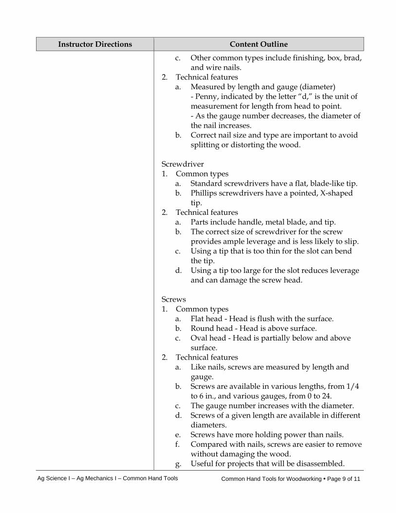
c. Other common types include finishing, box, brad, and wire nails.
2. Technical features a. Measured by length and gauge (diameter) - Penny, indicated by the letter “d,” is the unit of
measurement for length from head to point. - As the gauge number decreases, the diameter of
the nail increases. b. Correct nail size and type are important to avoid
splitting or distorting the wood. Screwdriver 1. Common types
a. Standard screwdrivers have a flat, blade-like tip. b. Phillips screwdrivers have a pointed, X-shaped
tip. 2. Technical features
a. Parts include handle, metal blade, and tip. b. The correct size of screwdriver for the screw
provides ample leverage and is less likely to slip. c. Using a tip that is too thin for the slot can bend
the tip. d. Using a tip too large for the slot reduces leverage
and can damage the screw head. Screws 1. Common types
a. Flat head - Head is flush with the surface. b. Round head - Head is above surface. c. Oval head - Head is partially below and above
surface. 2. Technical features
a. Like nails, screws are measured by length and gauge.
b. Screws are available in various lengths, from 1/4 to 6 in., and various gauges, from 0 to 24.
c. The gauge number increases with the diameter. d. Screws of a given length are available in different
diameters. e. Screws have more holding power than nails. f. Compared with nails, screws are easier to remove
without damaging the wood. g. Useful for projects that will be disassembled.
Ag Science I – Ag Mechanics I – Common Hand Tools Common Hand Tools for Woodworking • Page 10 of 11
Instructor Directions Content Outline
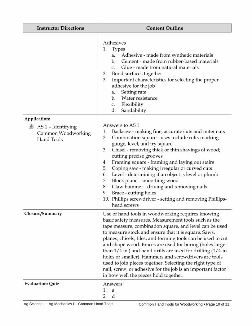
Adhesives 1. Types
a. Adhesive - made from synthetic materials b. Cement - made from rubber-based materials c. Glue - made from natural materials
2. Bond surfaces together 3. Important characteristics for selecting the proper
adhesive for the job a. Setting rate b. Water resistance c. Flexibility d. Sandability
Application:
AS 1 – Identifying Common Woodworking Hand Tools
Answers to AS 1 1. Backsaw - making fine, accurate cuts and miter cuts 2. Combination square - uses include rule, marking
gauge, level, and try square 3. Chisel - removing thick or thin shavings of wood;
cutting precise grooves 4. Framing square - framing and laying out stairs 5. Coping saw - making irregular or curved cuts 6. Level - determining if an object is level or plumb 7. Block plane - smoothing wood 8. Claw hammer - driving and removing nails 9. Brace - cutting holes 10. Phillips screwdriver - setting and removing Phillips-
head screws Closure/Summary Use of hand tools in woodworking requires knowing
basic safety measures. Measurement tools such as the tape measure, combination square, and level can be used to measure stock and ensure that it is square. Saws, planes, chisels, files, and forming tools can be used to cut and shape wood. Braces are used for boring (holes larger than 1/4 in.) and hand drills are used for drilling (1/4-in. holes or smaller). Hammers and screwdrivers are tools used to join pieces together. Selecting the right type of nail, screw, or adhesive for the job is an important factor in how well the pieces hold together.
Evaluation: Quiz Answers: 1. a 2. d
Ag Science I – Ag Mechanics I – Common Hand Tools Common Hand Tools for Woodworking • Page 11 of 11
Instructor Directions Content Outline
3. d 4. a 5. b 6. c 7. a 8. c 9. b 10. d 11. Students should provide five of the following:
a. Follow instructions from labels and warnings on containers, manufacturer’s recommendations for use and maintenance, signs posted in the work area, and directions given by the instructor.
b. Wear safety glasses in the shop at all times. c. Wear protective clothing such gloves, earplugs,
and safety shoes if appropriate. d. Avoid loose-fitting clothing that can get caught in
moving parts. e. Secure long hair with a hair net to avoid getting it
caught. f. Keep work areas clean. g. Inspect tools before using. h. Report any damaged tool to the instructor. i. Do not use a tool that is not functioning correctly. j. Return each tool to its proper place of storage.
12. A rasp's teeth are separate and raised and not in continuous rows. A rasp is generally used for rough work and forming where a lot of material needs to be removed.
13. a. Nails b. Screws c. Adhesives
14. a. When better holding power is required b. When the work needs to be assembled and
disassembled 15. Student may name two of the following reasons:
a. The correct size screwdriver provides ample leverage.
b. The correct size screwdriver is less likely to slip from the screw head.
c. An incorrect tip size can damage the tip or screw head.
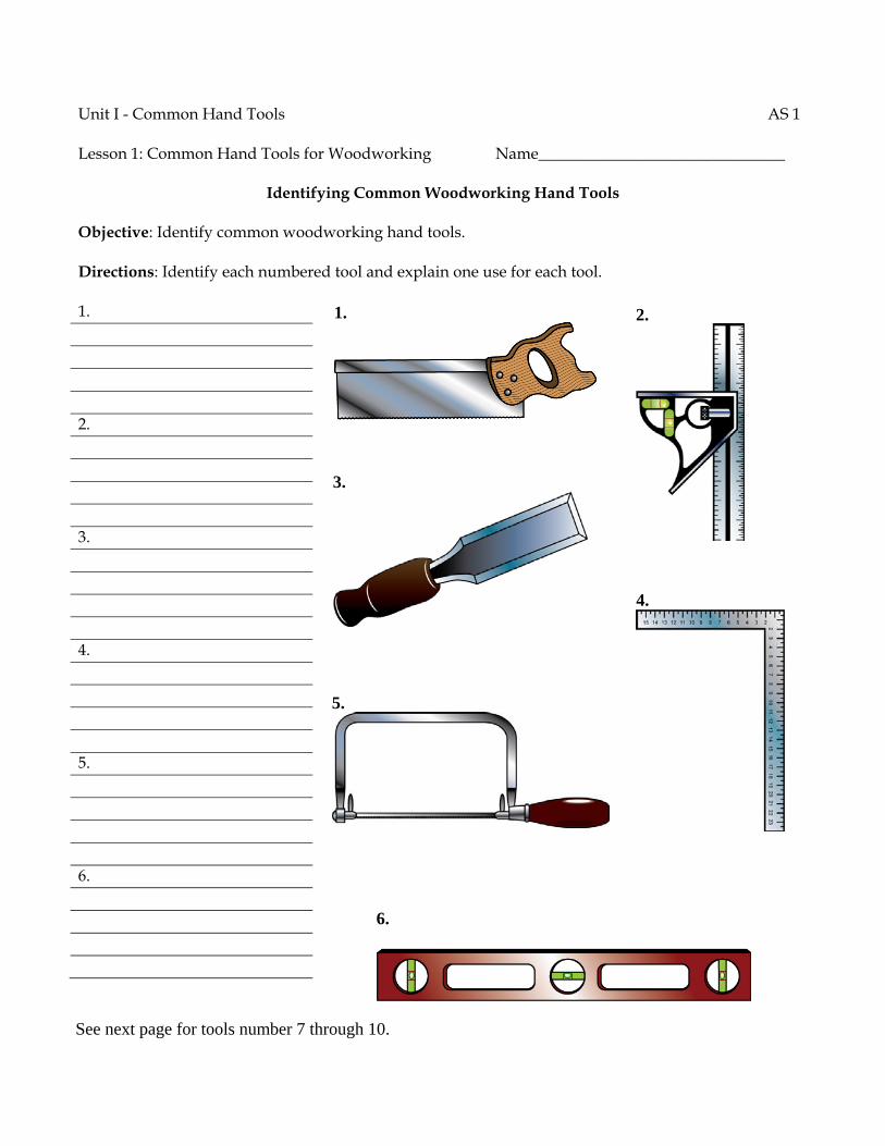
Unit I - Common Hand Tools AS 1 Lesson 1: Common Hand Tools for Woodworking Name_______________________________
Identifying Common Woodworking Hand Tools
Objective: Identify common woodworking hand tools. Directions: Identify each numbered tool and explain one use for each tool. 1. 2. 3. 4. 5. 6.
2. 1.
5.
6.
3.
4.
See next page for tools number 7 through 10.
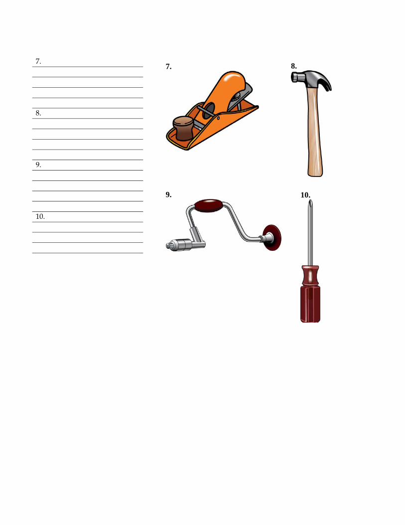
7. 8. 9. 10.
7.
9.
10.
8.
Unit I - Common Hand Tools Name_______________________________ Lesson 1: Common Hand Tools for Woodworking Date________________________________
Assessment
Circle the letter that corresponds to the correct answer. 1. A correct statement about a framing square is that it: a. is used for laying out stairs. b. is shaped like a triangle. c. includes a bubble tube for finding level. d. is used as a marking gauge. 2. A level can be used for: a. measuring circumference: b. measuring area. c. marking cut lines. d. finding plumb. 3. When making a straight cut with the grain of the wood, which saw is the best choice? a. Backsaw b. Coping c. Crosscut d. Ripsaw 4. When a very accurate cut is required in cutting a joint, which saw is the best choice? a. Backsaw b. Coping c. Crosscut d. Ripsaw 5. When a very fine cut is required in cutting a curve, which saw is the best choice? a. Backsaw b. Coping c. Crosscut d. Ripsaw

6. Which tool is the best choice to smooth the long edge of a board? a. Chisel b. File c. Plane d. Rasp 7. Which tool is the best choice for making a dado? a. Chisel b. File c. Plane d. Rasp 8. The term “drilling” is typically used for making holes that are: a. 3/8 in. or smaller. b. 3/8 in. or larger. c. 1/4 in. or smaller. d. 1/4 in. or larger. 9. The size of a brace is determined by: a. its chuck capacity. b. its sweep. c. the size of its handle. d. the size of its ratchet. 10. The length of nails is designated by which system? a. Metric b. U.S. Customary c. Dime d. Penny

Complete the following short-answer questions. 11. Provide five general safety precautions that apply to agricultural mechanics shop
environments. a. b. c. d. e. 12. How is a rasp's teeth design different from a file's? What is a rasp generally used for? 13. The three general types of woodworking fasteners discussed in the lesson are: a. b. c. 14. When would a screw be a better choice as a fastener than a nail? Provide two reasons. a. b. 15. Provide two reasons why it is important to select the correct size screwdriver for the screw
head. a.
b.
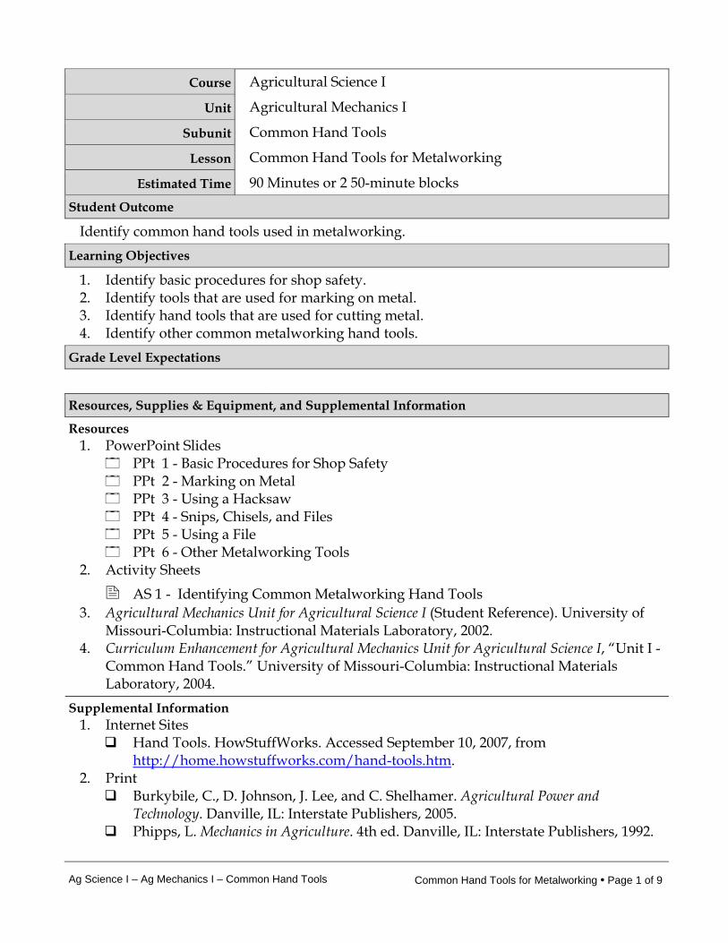
Ag Science I – Ag Mechanics I – Common Hand Tools Common Hand Tools for Metalworking • Page 1 of 9
Course Agricultural Science I
Unit Agricultural Mechanics I
Subunit Common Hand Tools
Lesson Common Hand Tools for Metalworking
Estimated Time 90 Minutes or 2 50-minute blocks Student Outcome
Identify common hand tools used in metalworking. Learning Objectives
1. Identify basic procedures for shop safety. 2. Identify tools that are used for marking on metal. 3. Identify hand tools that are used for cutting metal. 4. Identify other common metalworking hand tools.
Grade Level Expectations
Resources, Supplies & Equipment, and Supplemental Information
Resources 1. PowerPoint Slides
PPt 1 - Basic Procedures for Shop Safety PPt 2 - Marking on Metal PPt 3 - Using a Hacksaw PPt 4 - Snips, Chisels, and Files PPt 5 - Using a File PPt 6 - Other Metalworking Tools
2. Activity Sheets
AS 1 - Identifying Common Metalworking Hand Tools 3. Agricultural Mechanics Unit for Agricultural Science I (Student Reference). University of
Missouri-Columbia: Instructional Materials Laboratory, 2002. 4. Curriculum Enhancement for Agricultural Mechanics Unit for Agricultural Science I, “Unit I -
Common Hand Tools.” University of Missouri-Columbia: Instructional Materials Laboratory, 2004.
Supplemental Information 1. Internet Sites
Hand Tools. HowStuffWorks. Accessed September 10, 2007, from http://home.howstuffworks.com/hand-tools.htm.
2. Print Burkybile, C., D. Johnson, J. Lee, and C. Shelhamer. Agricultural Power and
Technology. Danville, IL: Interstate Publishers, 2005. Phipps, L. Mechanics in Agriculture. 4th ed. Danville, IL: Interstate Publishers, 1992.
Ag Science I – Ag Mechanics I – Common Hand Tools Common Hand Tools for Metalworking • Page 2 of 9
Phipps, L., and G. Miller. Introduction to Agricultural Mechanics. Upper Saddle River, NJ: Prentice Hall Interstate, 2004.
3. Electronic Media Smartflix offers a line of videos related to metalworking that can be rented from
their Web site. Accessed September 12, 2007, from http://smartflix.com/store/category/115/Metalworking.
Ag Science I – Ag Mechanics I – Common Hand Tools Common Hand Tools for Metalworking • Page 3 of 9
Instructor Directions Content Outline
Objective 1
The list of basic shop safety procedures that appears in the previous lesson is repeated here in case the lessons are not presented in sequence. Refer to PPt 1.
PPt 1 – Basic Procedures for Shop Safety
Identify basic procedures for shop safety. Adhere to instructions from the following sources: 1. Labels and warnings on containers and tools 2. The manufacturer’s recommendations for use and
maintenance of specific tools 3. Signs posted in the work area 4. Directions given by the instructor Wear safety glasses in the shop at all times. Wear protective gear such as gloves, earplugs, and safety shoes if appropriate. Do not wear loose-fitting clothing that could get caught in a moving part. Wear a hair net to prevent long hair from getting caught in a tool. Keep work areas clean and free of clutter.
Interest Approach
1. Like woodworking tools, metalworking tools can be considered based on the jobs they do. There are fastening tools like screwdrivers and wrenches, cutting tools like saws, chisels, and so on. Ask students what sorts of metalworking jobs they would likely encounter and which hand tool they would choose for the job and why. If it is a job for which different tools could be used, such as cutting, which can be done with a saw, shears, or a chisel, what factors might make one tool better for the job than another?
2. Show students tools that are either in need of reconditioning or are put together
incorrectly. Examples could include a screwdriver with a broken or worn tip, a ball-peen hammer with a loose head or broken handle, a cold chisel with a dull edge and mushroomed head, or a hacksaw with the blade in backward. Ask students to identify what is wrong with each tool, why this would be a problem, and how it should be fixed. (Reconditioning screwdrivers and chisels is discussed in Unit IV Lesson 1.)
Communicate the Learning Objectives
1. Identify basic procedures for shop safety. 2. Identify tools that are used for marking on metal. 3. Identify hand tools that are used for cutting metal. 4. Identify other common metalworking hand tools.
Ag Science I – Ag Mechanics I – Common Hand Tools Common Hand Tools for Metalworking • Page 4 of 9
Instructor Directions Content Outline
Inspect each tool before using it to make sure it is working properly. Tell the instructor about any damaged tool. Do not use a tool that does not function properly. Return each tool to its proper place of storage.
Objective 2
Tools for marking metalwork place marks that adhere to or scratch the surface of the metal. Refer to PPt 2.
PPt 2 – Marking on Metal
Identify tools that are used for marking on metal. Scratch awl 1. Used with a straightedge to scratch straight lines 2. Must be kept sharp to ensure fine, accurate marks Dividers 1. Consist of two steel legs with sharp points 2. Used for scribing arcs and circles 3. Used to transfer measurements Soapstone 1. Soft, gray rock 2. May be cut and used like a pencil 3. Marks the surface rather than scratches it 4. Harder to rub off than a chalk or pencil mark Permanent marker 1. Must be a hard-tipped, fine-point marker to make an
accurate line 2. Harder to rub off than a chalk or pencil mark 3. Safer than an awl Center punch 1. Steel punch with the end ground to a 90-degree angle 2. Makes a small dent in metal for marking the center of
a hole and starting a twist drill bit Objective 3
Hacksaws, shears and snips, cold chisels, and files are hand tools used for cutting metal and removing unwanted material. Refer to PPt 3-5. (Sharpening a
Identify hand tools that are used for cutting metal. Hacksaw 1. Two kinds of blades
a. Solid or all-hard blade - Entire blade hardened - Good for cutting tool steel, cast iron, and larger
Ag Science I – Ag Mechanics I – Common Hand Tools Common Hand Tools for Metalworking • Page 5 of 9
Instructor Directions Content Outline
cold chisel is covered in Unit IV Lesson 1.)
PPt 3 – Using a Hacksaw
PPt 4 – Snips, Chisels, and Files
PPt 5 –Using a File
pieces of mild steel - Good for long-term use b. Flexible blade - Only teeth are hardened - Good for cutting channel iron, tubing, copper,
and aluminum - Stands up to short-term hard use
2. Technical features a. Parts include handle, frame, and blade - Removable blades - Blades designated by the number of teeth per
inch (pitch), ranging from 14 to 32 teeth per inch - Teeth face toward the front of the saw and away
from the handle b. Pitch is the most important factor in selecting the
right blade for the cut. c. When cutting, three teeth are on the metal at a
time to avoid breaking the teeth (too few teeth) or clogging the teeth (too many teeth).
d. Cut is made on the forward stroke. e. If a blade must be changed in the middle of a cut,
the work should be turned and a new cut should be started to meet the previous cut. This is done because the positioning of the new blade’s teeth (their set) will not match the old blade’s set and the new blade will be damaged.
Shears and snips 1. Scissor-like tools for cutting wire and sheet metal 2. Regular snips do all their work by the force applied
by the operator. They are useful for cutting thin metal.
3. Compound or aviation snips have compound handles that increase leverage for cutting heavier stock.
Cold chisel 1. Uses
a. Cutting and shearing b. Cutting grooves
2. Common types a. Flat - used for general cutting and shearing b. Round-nose - used for cutting round grooves c. Diamond - used for cutting square grooves and
Ag Science I – Ag Mechanics I – Common Hand Tools Common Hand Tools for Metalworking • Page 6 of 9
Instructor Directions Content Outline
corners d. Cape - used for cutting narrow rectangular
grooves 3. Technical features
a. Parts include the cutting edge, body, and head. b. The cutting edge and head must be kept ground
to the proper angle and shape. - The head can become deformed, or
mushroomed, from use. - The cutting edge of a flat chisel should be
ground to an angle of 60 or 70 degrees. - Sharpening and reconditioning are done with a
grinder. Files 1. Uses
a. Shaping the work b. Removing material c. Finishing the surface
2. Classification is based on cut (pattern of teeth), shape, and coarseness a. Single cut - parallel rows of teeth going in the
same direction b. Double cut - rows of teeth cross one another c. Rasp cut - separate teeth, not continuous rows of
teeth d. Curve cut - pattern of teeth curves e. Shapes - flat, round, and half-round f. Coarseness - bastard cut, second cut, and smooth
cut 3. Filing techniques
a. Cross-filing - File strokes are crossed. - Cross-filing is used to remove a lot of material
quickly. - Double-cut files are used for cross-filing. b. Draw filing - The file is held at 90-degree angle to stock and
pulled or pushed along the length of the work. - Draw filing is used to produce a finer finish
than cross-filing. - Single-cut files are used for draw filing.
4. Safety measures
Ag Science I – Ag Mechanics I – Common Hand Tools Common Hand Tools for Metalworking • Page 7 of 9
Instructor Directions Content Outline
a. Work that is filed must be in a vise or other device to hold it firmly.
b. Files should always be used with a handle on the tang to prevent serious injury.
Objective 4
Hammers, screwdrivers, wrenches, and a bench vise are among some of the other tools used in metalworking. Discuss any other tools that are relevant or ask students what metalworking hand tools they find to be most useful. Refer to PPt 6. Have students complete AS 1 to identify the names and uses of common hand tools for metalworking.
PPt 6 – Other
Metalworking Tools
AS 1 – Identifying Common Metalworking Hand Tools
Identify other common metalworking hand tools.
Hammer 1. Ball-peen hammer
a. Steel head b. Available in different sizes based on weight of
head, ranging from 2 oz to 3 lb c. Delivers flat blows, bends stock, and shapes the
surface with rounded dents (peens) 2. Soft-faced hammer
a. Made of soft material, such as plastic, rawhide, brass, and wood
b. Drives parts without marring surface c. Used in assembly and disassembly where a steel-
head hammer could damage parts Screwdriver 1. Used in fastening pieces together 2. Common types
a. Standard - flat blade-like tip b. Phillips - pointed, X-shaped tip
3. Technical features a. Parts include handle, metal blade, and tip. b. Tip should fit the slot of the screw as closely as
possible. - Using a tip that is too thin for the slot can bend
the tip. - Using a tip that is too big for the slot can reduce
leverage and damage the screw head. Wrench 1. Solid wrench
a. Types include open end, box end, combination (one open end, one box end), and socket
b. Designed to fit specific sizes of bolts c. Available in U.S. customary and metric sizes
2. Adjustable wrench a. Designed to adjust to different sizes of nuts and
bolts
Ag Science I – Ag Mechanics I – Common Hand Tools Common Hand Tools for Metalworking • Page 8 of 9
Instructor Directions Content Outline
b. Can replace several solid wrenches c. Types include adjustable open-end wrench, pipe
wrench, and monkey wrench d. Should be seated and tightened properly to the
nut so wrench does not slip Bench vise 1. Holds work for filing, sawing, and other operations 2. Can be used with jaw caps (soft materials like
aluminum or brass) to avoid marring stock or with inserts to hold round or odd-shaped work
Application:
AS 1 – Identifying Common Woodworking Hand Tools
Answers to AS 1 1. Adjustable wrench - used to tighten or loosen nuts or
bolts 2. Scratch awl - used with a straightedge to scratch
straight lines in metal 3. Ball-peen hammer - used to deliver flat blows, bend
stock, or shape the surface with rounded dents 4. Center punch - used to make a small dent in metal for
marking the center of a hole 5. Flat chisel - used for chipping and shearing 6. Dividers - used for scribing arcs and circles and
transferring dimensions from one scale or object to another
7. Flat file - used for shaping, removing material, and finishing a surface
8. Hacksaw - used for cutting metal 9. Flathead or standard screwdriver - used for driving
and removing single-slot screws 10. Regular snips or snips - used for cutting thin metal
Closure/Summary Use of hand tools in metalworking requires following basic procedures for shop safety. Tools for marking metal include the scratch awl, dividers, permanent marker, and center punch. Hacksaws, shears and snips, and cold chisels are used to cut metal. The pitch of the hacksaw blade is the most important factor in selecting the right blade for the cut. Metalworking files can be used to shape the work, remove material, and finish the surface. Hammers, screwdrivers, and wrenches are used to fasten pieces together.
Ag Science I – Ag Mechanics I – Common Hand Tools Common Hand Tools for Metalworking • Page 9 of 9
Instructor Directions Content Outline Evaluation: Quiz Answers:
1. a 2. b 3. b 4. c 5. d 6. c 7. b 8. a. A pencil mark rubs off easily.
b. A pencil mark is hard to see. 9. Solid
a. Designed for long-term use b. Used on tool steel, cast iron, and larger pieces of
mild steel (student to provide at least one) Flexible
c. Designed for short-term use d. Used on channel iron, tubing, copper, and
aluminum (student to provide at least one) 10. a. One adjustable wrench can replace several solid
wrenches. b. An adjustable wrench can be used on odd-size
bolts or nuts. 11. Cross-filing
a. Used to remove a lot of material quickly b. Double c. A crossing stroke is used. Draw filing d. Used to produce a flat surface with a fine finish e. Single f. The file is held at a 90-degree angle and pulled or
pushed along the length of the work.
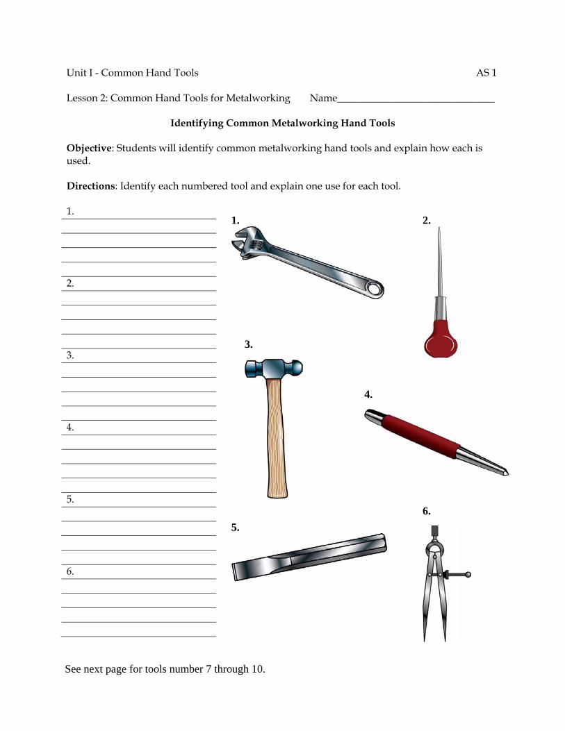
Unit I - Common Hand Tools AS 1 Lesson 2: Common Hand Tools for Metalworking Name_______________________________
Identifying Common Metalworking Hand Tools
Objective: Students will identify common metalworking hand tools and explain how each is used. Directions: Identify each numbered tool and explain one use for each tool. 1. 2. 3. 4. 5. 6.
5.
6.
3.
4.
1.
2.
See next page for tools number 7 through 10.
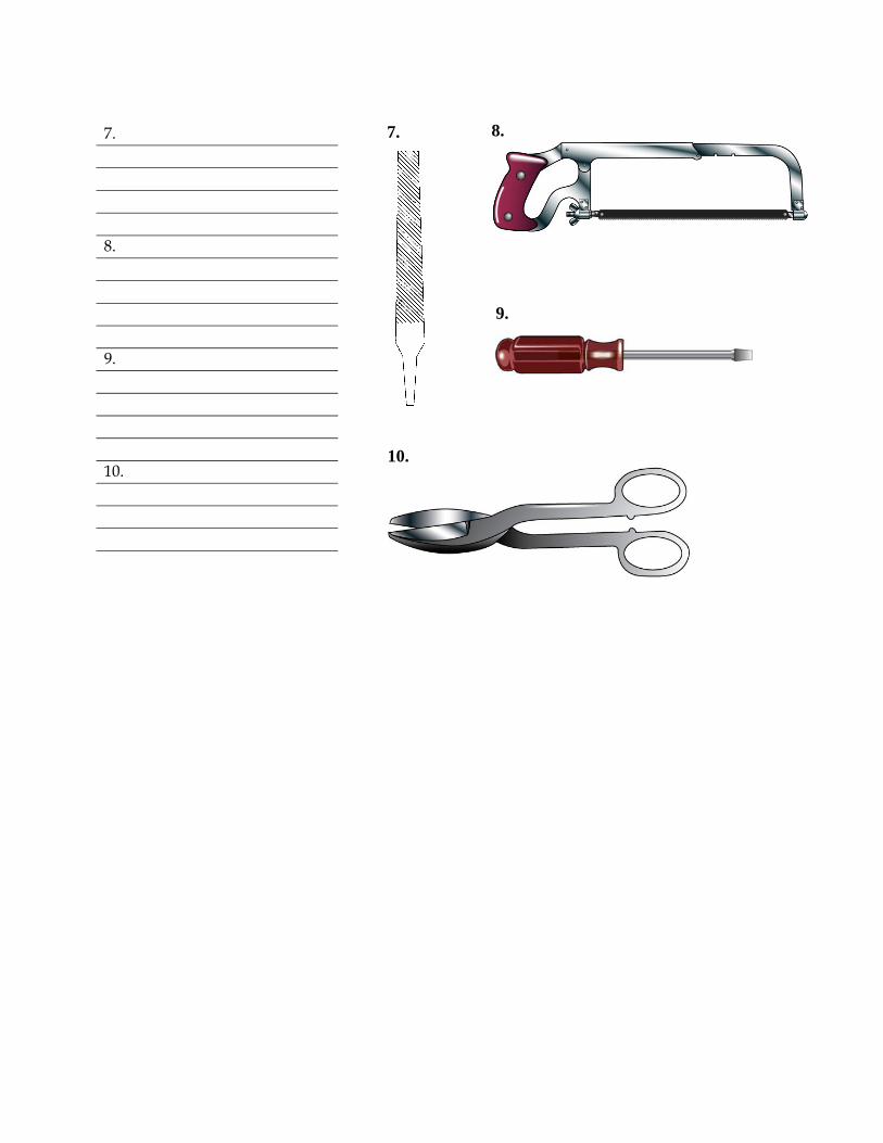
7. 8. 9. 10.
7.
9.
8.
10.

Unit I - Common Hand Tools Name______________________________ Lesson 2: Common Hand Tools for Metalworking Date_______________________________
Assessment
Circle the letter that corresponds to the correct answer. 1. Which tool is commonly used to mark the location of a hole to be drilled in metal? a. Center punch b. Dividers c. Scratch awl d. Soapstone 2. Which tool is best suited for scribing arcs and circles on metal? a. Center punch b. Dividers c. Scratch awl d. Soapstone 3. When cutting with a hacksaw, what is the correct number of teeth that should be on the
metal at all times? a. Two b. Three c. Four d. Five 4. Snips are used on metal to: a. shape. b. mark. c. cut. d. chip. 5. Which type of hammer is frequently used to bend or shape metal? a. Soft faced b. Curved claw c. Claw d. Ball peen
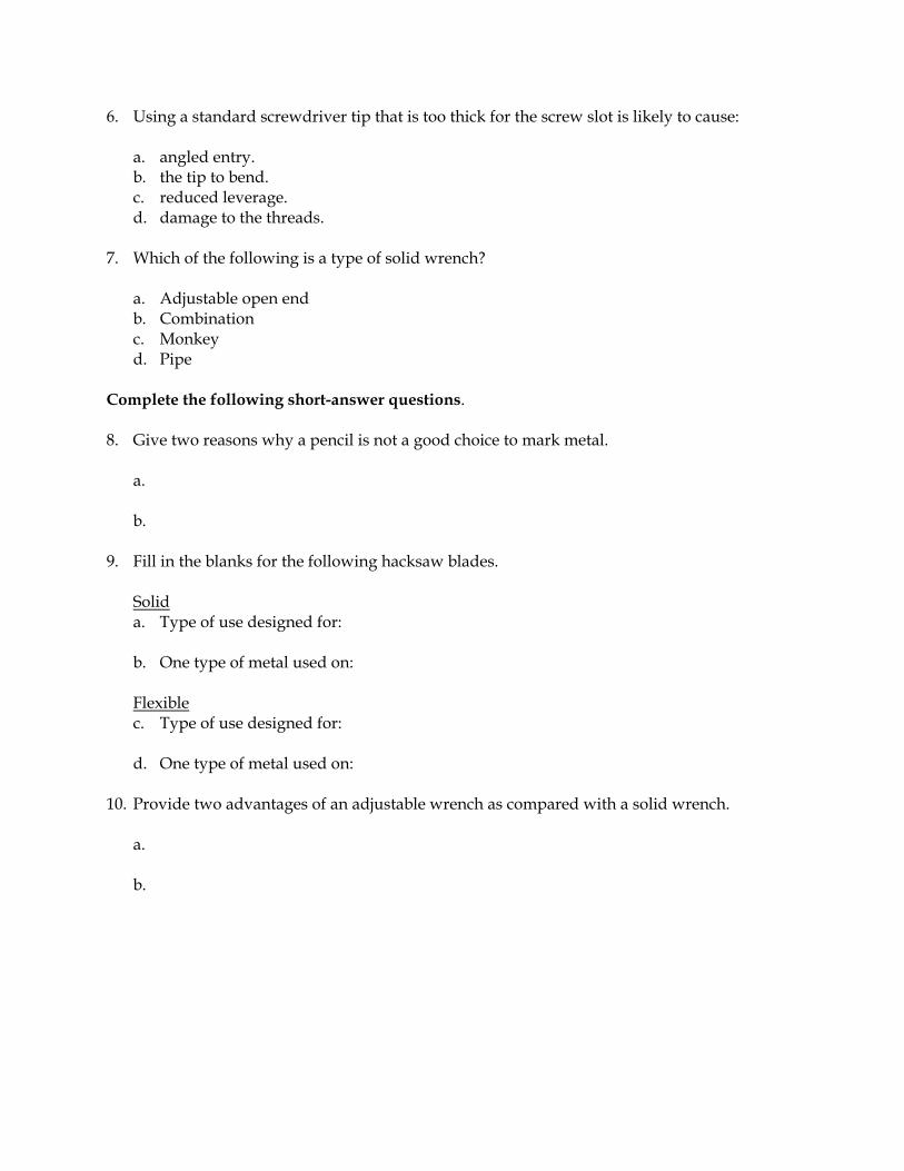
6. Using a standard screwdriver tip that is too thick for the screw slot is likely to cause: a. angled entry. b. the tip to bend. c. reduced leverage. d. damage to the threads. 7. Which of the following is a type of solid wrench? a. Adjustable open end b. Combination c. Monkey d. Pipe Complete the following short-answer questions. 8. Give two reasons why a pencil is not a good choice to mark metal. a. b. 9. Fill in the blanks for the following hacksaw blades. Solid a. Type of use designed for: b. One type of metal used on: Flexible
c. Type of use designed for:
d. One type of metal used on: 10. Provide two advantages of an adjustable wrench as compared with a solid wrench. a. b.

11. Fill in the blanks below for the following filing techniques. Cross-filing
a. Purpose: b. Type of file cut used: c. Stroke used: Draw filing
d. Purpose: e. Type of file cut used: f. Stroke used:

Unit I - Common Hand Tools Unit I Activity
Name_______________________________
Woodworking and Metalworking Tool Collection Objective: Plan a hand tool collection for woodworking and metalworking. Directions: It is your job to buy tools for a new woodworking and metalworking shop. Price tools at a hardware store, home center, or on the Internet. Your instructor will give you a budget and you will have to justify the purchases you would make. Answer the questions below. Materials and Equipment: Catalog or price list from a hardware store or the Internet Key Questions: 1. What tools would you buy to make up a basic kit of hand tools? Why? 2. Would you always choose the cheapest or the most expensive tool? Why or why not? 3. Are there any tools, such as a saw, or materials, such as fasteners, that you would need to buy more
than one of? What are they? 4. Can some of the tools be used for both woodworking and metalworking? What are they?

5. What safety equipment would you purchase? Why? 6. How much would this set of tools cost? 7. Was it easier or harder to stay within the budget than you thought it would be? 8. Were you able to buy all the tools you felt you needed for the basic tool kit? 9. If not, what tools were you unable to buy? 10. How important do you think it is to clean, recondition, and maintain the tools and why?
♦ Page 1 ♦
Agricultural Science I Curriculum Guide: Agricultural Mechanics Unit for Agricultural Science I Unit: I. Common Hand Tools Unit Objective:
Students will demonstrate an understanding of common hand tools used in woodworking and metalworking by designing, organizing, and participating in a tool identification contest.
Show-Me Standards: 1.8, CA6 References:
Agricultural Mechanics Unit for Agricultural Science I. University of Missouri-Columbia, Instructional Materials Laboratory, 2002. Craftsman. Accessed November 7, 2003, from www.craftsman.com/. Missouri CDE Handbook. Accessed November 6, 2003, from http://www.dese.mo.gov/divcareered/ag_cde_guidelines.htm. Missouri FFA Agricultural Mechanics Career Development Event. Accessed November 19, 2003, from http://web.missouri.edu/~pavt0689/statecon.html. Sears, Roebuck, and Co. Accessed November 25, 2003, from www.sears.com. SK Hand Tool Corporation. Accessed November 7, 2003, from http://www.skhandtool.com/. Snap-on Technologies, Inc. Accessed November 7, 2003, from http://www.snapon.com/. Students may use additional outside sources to complete this activity.
Instructional Strategies/Activities: • Students will engage in study questions in lessons 1 and 2. • Students will complete AS 1.1, Identifying Common Woodworking Hand
Tools; and AS 2.1, Identifying Common Metalworking Hand Tools. • Additional activities that relate to the unit objective can be found under
the heading “Unit I Activity” in the following location: p. I-59.
Agricultural Science I
♦ Page 2 ♦
Performance-Based Assessment: Students will work in groups to design, organize, and participate in a tool identification contest, similar to the tool identification portion of the Agricultural Mechanics Career Development Event. Each group will be responsible for a portion of the tools in the contest and will also compete as a team in the whole event. Assessment will be based on the content and presentation of the assigned tool display and performance in the whole event.
Agricultural Science I
♦ Page 3 ♦
Agricultural Mechanics Unit for Agricultural Science I Unit I—Common Hand Tools Instructor Guide The instructor should assign the performance-based assessment activity at the beginning of the unit. Students will work toward completing the activity as they progress through the unit lessons. The assessment activity will be due at the completion of the unit. 1. Divide students into groups and assign each group a list of common
woodworking and metalworking hand tools to collect for a tool identification contest. a. Each group will also compete in the whole event as a team. b. Lists should only include tools that have been discussed by the instructor
with all the students as a group.
2. This activity will help prepare students for the tool identification portion of the Agricultural Mechanics Career Development Event. a. Explain or review event guidelines as needed. b. Refer to the Missouri CDE Handbook for guidelines regarding the
Agricultural Mechanics Career Development Event. The Missouri CDE Handbook is available from the Missouri Department of Elementary and Secondary Education at http://www.dese.mo.gov/divcareered/ag_cde_guidelines.htm.
3. Have students collect their assigned hand tools and display them at a station
in the event. 4. Students may consult the instructor for assistance if they have difficulty
locating specific tools, but they must be responsible for the overall content and presentation of their portion of the event. Pictures may be substituted for actual tools, if desired.
5. Verify the students’ identification of their assigned tools prior to the contest
and suggest corrections as needed. 6. Have students identify the tools. Use the tool identification form and tool list
found in the Missouri CDE Handbook or use a different tool ID form, if preferred. a. Have each student identify all the tools in the contest to determine the
student’s individual score. b. Combine the individual scores of the group members to determine the
team score for each group.
Agricultural Science I
♦ Page 4 ♦
7. The final assessment score will be based on the content and presentation of the assigned tool display and the student’s individual contestant score.
8. Present an appropriate award to the high-scoring team and individual, if
desired. 9. NOTE: The following units in this curriculum guide also include material and
competencies that are addressed by the Agricultural Mechanics Career Development Event: Unit IV, Tool Sharpening and Reconditioning; Unit V, Arc Welding; and Unit VI, Oxyfuel Cutting. Some or all of the performance-based assessment activities for these units could be combined to form a mini Agricultural Mechanics Career Development Event, if desired. To conduct a mini Agricultural Mechanics Career Development Event, maintain the same student groups for all of the performance-based assessment activities. An expanded score sheet is included at the end of each of these units that can be used to track individual and group performance in the mini CDE.
10. ADDITIONAL ACTIVITIES:
a. Have a scavenger hunt for tools. Give each student the name of a tool in the shop. Have students locate and present their assigned tool. Guide or correct students’ tool selections as needed. Have students return the tools to their assigned location following the scavenger hunt.
b. Have students locate pictures of tools in catalogs or from tool manufacturers’ web sites. Have students paste the pictures onto index cards to make tool identification cards. Tool ID cards could be used as flash cards for review or in place of actual tools in the tool identification activity above.
c. For further review, an additional unit-level activity, Woodworking and Metalworking Tool Collection, is included on p. I-59 of the Instructor Guide. This activity requires students to plan a hand tool collection for the shop based on a budget set by the instructor. Students must list the tools they would purchase, answer key questions about the tools, and stay within their budget. The purpose of this activity is to familiarize students with a variety of hand tools and to emphasize the importance of choosing tools wisely and taking care of the tools that are available. Answers will vary.
Agricultural Science I
♦ Page 5 ♦
Agricultural Mechanics Unit for Agricultural Science I Unit I—Common Hand Tools Student Handout 1. You will work with a group to collect woodworking and metalworking hand
tools for a tool identification contest. 2. Your group will also compete in the whole event as a team. 3. You will be responsible for the content and presentation of your portion of
the contest. 4. Your final assessment score will be based on the content and presentation of
your assigned tool display and your individual contestant score.

Agricultural Science I
♦ Page 6 ♦
Agricultural Science I
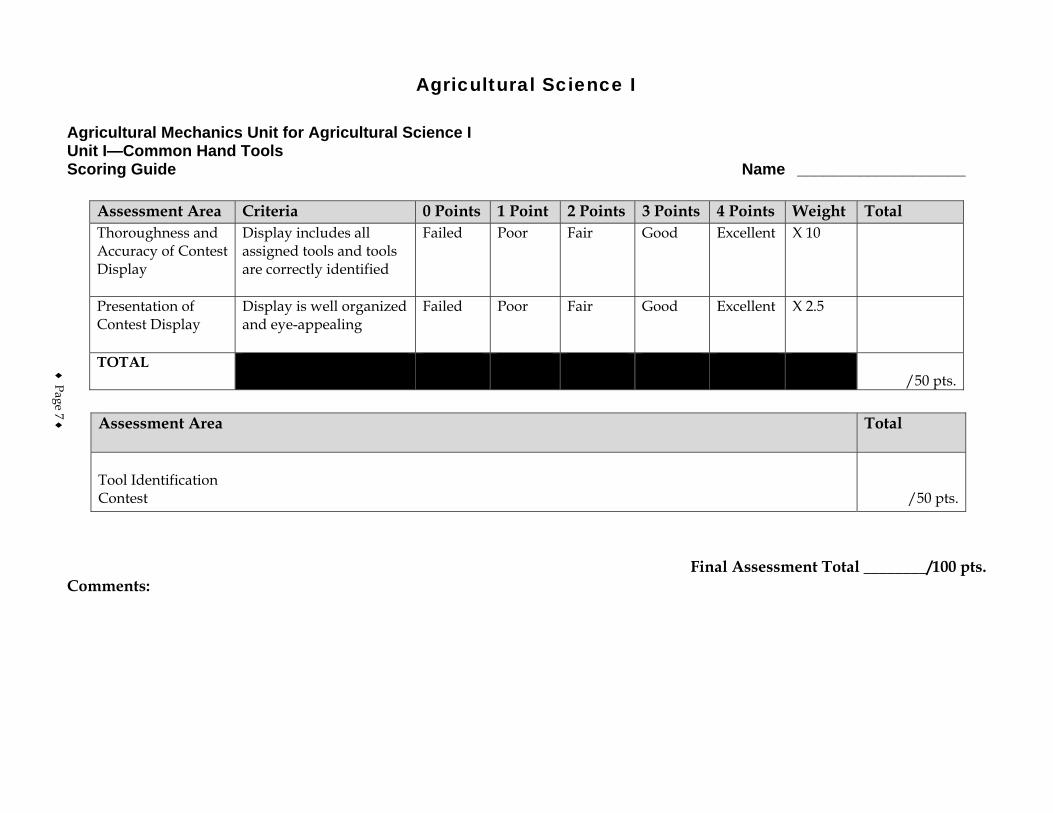
Agricultural Mechanics Unit for Agricultural Science I Unit I—Common Hand Tools Scoring Guide Name ___________________
Assessment Area Criteria 0 Points 1 Point 2 Points 3 Points 4 Points Weight Total Thoroughness and Accuracy of Contest Display
Display includes all assigned tools and tools are correctly identified
Failed Poor Fair Good Excellent X 10
Presentation of Contest Display
Display is well organized and eye-appealing
Failed Poor Fair Good Excellent X 2.5
TOTAL /50 pts.
Assessment Area
Total
Tool Identification Contest
/50 pts.
Final Assessment Total ________/100 pts. Comments:
♦ Page 7 ♦

♦ Page 8 ♦

♦ Page 9 ♦
Agricultural Mechanics I Score Sheet
Team Members Tool ID
Tool Sharpening/
Reconditioning Arc
Welding Oxyfuel Cutting Score
Team A Total: Team B Total: Team C Total: Team D Total: Team E Total: Team F Total:

♦ Page 10 ♦
Ag Science I – Ag Mechanics I – Common Power Tools Safe Use and Maintenance of Power Tools for Woodworking Page 1 of 14
Course Agricultural Science I
Unit Agricultural Mechanics I
Subunit Common Power Tools
Lesson Safe Use and Maintenance of Power Tools for Woodworking
Estimated Time 90 Minutes or 2 50-minute blocks Student Outcome
Analyze the uses and safety procedures of common power tools used in woodworking. Learning Objectives
1. Identify common sources of power for woodworking tools. 2. Identify some safeguards for the use of power tools. 3. List the uses and safeguards for a portable drill. 4. List the uses and safeguards for a portable circular saw. 5. List the uses and safeguards for a reciprocating saw. 6. List the uses and safeguards for a band saw. 7. List the uses and safeguards for a table saw. 8. List the uses and safeguards for a shaper. 9. List the uses and safeguards for a jointer.
Grade Level Expectations
Resources, Supplies & Equipment, and Supplemental Information
Resources 1. PowerPoint Slides
PPt 1 - Portable Drill PPt 2 - Circular Saw PPt 3 - Reciprocating Saw PPt 4 - Band Saw PPt 5 - Table Saw PPt 6 - Use of a Push Stick With a Table Saw PPt 7 - Shaper PPt 8 - Jointer
2. Activity Sheet
AS 1 - Safety and Maintenance Procedures for Power Tools for Woodworking 3. Agricultural Mechanics Unit for Agricultural Science I (Student Reference). University of
Missouri-Columbia: Instructional Materials Laboratory, 2002. 4. Curriculum Enhancement for Agricultural Mechanics Unit for Agricultural Science I, “Unit II -
Common Power Tools.” University of Missouri-Columbia: Instructional Materials Laboratory, 2004.
Ag Science I – Ag Mechanics I – Common Power Tools Safe Use and Maintenance of Power Tools for Woodworking Page 2 of 14
Supplemental Information 1. Internet Sites
The Free Plan and Project List. Buildeazy. Accessed September 12, 2007, from http://www.buildeazy.com/fp_start.html.
Hand and Power Tools. Occupational Safety and Health Administration. U. S. Department of Labor. Accessed September 12, 2007, from http://www.osha.gov/SLTC/handpowertools/index.html.
My Woodworking Expert. Accessed September 12, 2007, from http://www.mywoodworkingexpert.com/.
Recalls and Product Safety News. U. S. Consumer Product Safety Commission. Accessed September 12, 2007, from http://www.cpsc.gov/cpscpub/prerel/prerel.html.
Woodworking Online. Accessed September 12, 2007, from http://www.woodworkingonline.com/category/power-tools/.
2. Print Burkybile, C., D. Johnson, J. Lee, and C. Shelhamer. Agricultural Power and
Technology. Danville, IL: Interstate Publishers, 2005. Phipps, L. and G. Miller. Introduction to Agricultural Mechanics. Upper Saddle River,
NJ: Prentice Hall Interstate, 2004. 3. Electronic Media
The Power Tool Institute offers a line of free videos on safety that can be found at http://www.powertoolinstitute.com/education.html. Accessed September 12, 2007.
Ag Science I – Ag Mechanics I – Common Power Tools Safe Use and Maintenance of Power Tools for Woodworking Page 3 of 14
Instructor Directions Content Outline
Objective 1 Basic shop safety procedures were covered in Unit I Lessons 1 and 2. As an introduction to this lesson, review these procedures as needed. Electricity and compressed air are common power sources for woodworking tools. In addition to the general safety precautions, there are safety considerations specific to electric and air-driven (pneumatic) tools. These are discussed below.
Identify common sources of power for woodworking tools.
1. Electricity, including battery packs 2. Compressed air (pneumatic tools)
Interest Approach
1. Conduct a demonstration of drilling two 1/2 inch holes in a board. For one hole, have a student use a brace and bit to drill the hole. For the second hole, use an electric power drill to drill the hole to demonstrate the speed of power tools.
2. Have a student cut a board with an appropriate wood saw. Compare the quality of cut
to that of a circular or table saw. 3. Hand out simple wood project plans that have a list of tools required. Have the
students use the Internet to search for the cost of one or two power tools. 4. Have students discuss safety measures for use of power tools and why safety
precautions are important. What could be the consequences of unsafe use of power tools?
Communicate the Learning Objectives
1. Identify common sources of power for woodworking tools. 2. Identify some safeguards for the use of power tools. 3. List the uses and safeguards for a portable drill. 4. List the uses and safeguards for a portable circular saw. 5. List the uses and safeguards for a reciprocating saw. 6. List the uses and safeguards for a band saw. 7. List the uses and safeguards for a table saw. 8. List the uses and safeguards for a shaper. 9. List the uses and safeguards for a jointer.
Ag Science I – Ag Mechanics I – Common Power Tools Safe Use and Maintenance of Power Tools for Woodworking Page 4 of 14
Instructor Directions Content Outline Objective 2
Identify some safeguards for the use of power tools.
Safety precautions for electric tools and battery-powered tools 1. Always unplug a tool or disconnect it from its battery
before inspecting it and making adjustments. 2. Only use a tool that is double insulated or has a
grounded plug. 3. Always plug a tool into a power source with a
ground-fault circuit interrupter (GFCI or GFI), which will shut off the electricity if a short occurs. If GFCIs are not installed, portable GFCIs can be plugged into grounded outlets.
4. Do not stand on wet ground or a wet surface while operating an electric tool.
5. Make sure stationary power tools are securely anchored to the floor.
6. Make sure all guards and shields are in place and vents are free of debris before operating an electric tool.
7. Do not bend the power cord sharply or use the cord to pull the plug from the outlet or carry the tool. Such actions could break the cord, and a broken cord is an electrical hazard.
8. Use only the battery specified by the manufacturer for the tool being used.
9. Use only the type of recharger designed for the batteries being used.
10. Always store battery packs safely so that no metal can come in contact with the terminals. This can short-circuit the battery and cause sparks, fire, or burns.
Safety precautions for pneumatic tools 1. Disconnect pneumatic tools for all inspections and
adjustments. 2. Do not join or separate quick-disconnect couplings on
high-pressure lines when bystanders are nearby. 3. Do not use compressed air for cleanup if the air
pressure is 30 lb per sq in. (psi) or greater. 4. Do not point an air stream at anyone. High-pressure
air can drive dust into the eyes, damage eardrums, and cause other types of injury.
5. Inspect couplings and air lines regularly for evidence

Ag Science I – Ag Mechanics I – Common Power Tools Safe Use and Maintenance of Power Tools for Woodworking Page 5 of 14
Instructor Directions Content Outline
of wear or damage. 6. Make sure air tanks and air lines are free of moisture
and appropriate filters are in place. 7. Follow the manufacturer’s recommendations for hose
size and maximum air pressure. 8. Oil pneumatic tools regularly according to
manufacturer recommendations. Objective 3
Refer to PPt 1 or display the actual tool when explaining the main parts and features. Discuss safety and maintenance considerations.
PPt 1 - Portable Drill
List the uses and safeguards for a portable drill.
Main parts 1. On/off switch 2. Power cord 3. Handle 4. Chuck 5. Chuck key Uses 1. Drilling and boring 2. Driving and removing screws 3. Sanding 4. Polishing 5. Powering hole saws Additional features 1. Available in different sizes 2. Size of drill determined by the chuck capacity (e.g., a
1/4-in. drill holds a drill bit with a shank no larger than 1/4 in.)
3. Single or variable speed 4. Reversible Safety considerations 1. Choose the correct bit for the job. For example, do not
use a square-shank bit in an electric drill. 2. Make sure the bit is tightly seated in the chuck,
securing it by turning the chuck key in each hole. Remove the chuck key before starting the drill.
3. Make sure the work is held securely in place. Use a clamp or vise to hold small work.
4. Hold the drill perpendicular to the work to avoid binding the bit.
Ag Science I – Ag Mechanics I – Common Power Tools Safe Use and Maintenance of Power Tools for Woodworking Page 6 of 14
Instructor Directions Content Outline
5. Remove the bit from the drill when work is completed.
Maintenance considerations 1. Follow the manufacturer’s instructions for regular
lubrication of parts. 2. Sharpen or replace dulled bits.
Objective 4
Refer to PPt 2 or display the actual tool when explaining the main parts and features. Discuss safety and maintenance considerations.
PPt 2 - Circular Saw
List the uses and safeguards for a portable circular saw.
Main parts 1. On/off switch 2. Power cord 3. Angle scale 4. Base 5. Angle adjustment lock 6. Handle 7. Blade guard 8. Blade Uses 1. Rip cuts 2. Crosscuts 3. Bevel cuts 4. Mitering Additional features 1. Available in different sizes 2. Size of portable circular saw determined by the
diameter of largest blade it will hold 3. Different types of blades for different kinds of cuts 4. Angle scale used to set the depth of the blade’s cut 5. Upward rotation of the blade produces splintering on
the topside of piece. Cut with the better side of the work face down.
Safety considerations 1. Choose the correct blade for the job. 2. Make sure base and angle adjustments are correct and
snug. 3. Back the saw slightly away from the work before
turning it on. The saw should be at full speed before beginning the cut.
Ag Science I – Ag Mechanics I – Common Power Tools Safe Use and Maintenance of Power Tools for Woodworking Page 7 of 14
Instructor Directions Content Outline
4. Cut only in a straight line to avoid binding the blade. 5. Wait until the blade stops moving before setting the
saw down. Maintenance considerations 1. Make sure the blade guard moves freely and covers
the blade completely when the saw is not in use. Small pieces of wood can become wedged in the guard and prevent it from closing over the blade.
2. Clean, sharpen, or replace dulled or gummy blades. Objective 5
Refer to PPt 3 or display the actual tool when explaining the main parts and features. Discuss safety and maintenance considerations.
PPt 3 - Reciprocating Saw
List the uses and safeguards for a reciprocating saw. Main parts 1. On/off switch 2. Power cord 3. Handle 4. Shoe 5. Blade Uses 1. Relief cuts 2. Irregular cuts 3. Crosscuts 4. Pocket cuts Additional features 1. Heavy duty yet compact in size, making it useful for
work in a close area where it would be difficult to operate a circular saw
2. Because of maneuverability, particularly useful for making irregular and pocket cuts
3. Different kinds of blades for cutting different types of materials, such as wood, metal, plastic, and plaster
4. Shoe adjusts for cutting at different depths Safety considerations 1. Choose the correct blade for the cut. 2. Choose the appropriate speed for the cut. Dense
materials are cut at a slower speed and soft materials are cut at a higher speed.
3. Make sure the saw is operating at full speed before beginning the cut.
Ag Science I – Ag Mechanics I – Common Power Tools Safe Use and Maintenance of Power Tools for Woodworking Page 8 of 14
Instructor Directions Content Outline
4. Hold the shoe against the work at all times. Maintenance considerations 1. Follow the manufacturer’s recommendations for
regular service. 2. Clean, sharpen, or replace blades as needed.
Objective 6
Refer to PPt 4 or display the actual tool when explaining the main parts and features. Discuss safety and maintenance considerations.
PPt 4 - Band Saw
List the uses and safeguards for a band saw. Main parts 1. On/off switch 2. Upper and lower wheels and wheel guards 3. Table 4. Blade 5. Upper and lower blade guides 6. Arm Uses 1. Straight cuts 2. Irregular cuts 3. Curved cuts 4. Bevel cuts Additional features 1. Size of band saw determined by the diameter of its
wheels (e.g., a 14-in. band saw has 14-in. wheels) 2. Thin blade forms a loop over the two wheels and
through the two blade guides 3. Upper and lower blade guides for holding blade on
wheels 4. Different types of blades for different cuts Safety considerations 1. Choose the correct blade for the cut and material. 2. Make sure the blade is held tightly in the saw and the
guide is within 1/8 in. of the piece. The teeth should point downward.
3. Plan the cut so the work and the waste piece of wood can be controlled. Make sure the board cannot strike the arm of the saw.
4. Turn off the saw immediately if the blade breaks or “clicks” during cutting. A clicking noise could indicate that the blade is cracked.
Ag Science I – Ag Mechanics I – Common Power Tools Safe Use and Maintenance of Power Tools for Woodworking Page 9 of 14
Instructor Directions Content Outline
5. Turn off the saw before backing out of a cut. Maintenance considerations 1. Maintain proper blade tension. 2. Maintain proper tracking of the blade. The blade
should stay at the center of the wheels. 3. Repair or replace broken blades.
Objective 7
Refer to PPts 5 and 6 or display the actual tool when explaining the main parts and features. Discuss safety and maintenance considerations.
PPt 5 - Table Saw
PPt 6 - Use of a Push Stick with a Table Saw
List the uses and safeguards for a table saw. Main parts 1. On/off switch 2. Blade-height adjustment wheel 3. Rip fence 4. Miter groove 5. Blade 6. Blade guard 7. Table 8. Blade-angle adjustment wheel Uses 1. Rip cuts 2. Crosscuts 3. Mitering 4. Bevel cuts 5. Joint making Additional features 1. Similar to a portable circular saw but in a stationary
setup 2. Size of table saw determined by the diameter of the
largest blade it will hold 3. Different kinds of blades, such as rip and crosscut
blades, for different kinds of cuts 4. Tilting arbor or tilting table allows saw to make angle
cuts 5. Rip fence used for straight rip cuts Safety considerations 1. Choose the correct blade for the cut. 2. Adjust the angle and height of the blade to
accommodate the cut. The teeth should point in the direction of the blade’s rotation.
Ag Science I – Ag Mechanics I – Common Power Tools Safe Use and Maintenance of Power Tools for Woodworking Page 10 of 14
Instructor Directions Content Outline
3. Stand to the side of the blade and do not reach across the table.
4. Keep hands at least 6 in. from the blade. 5. Use a push stick to guide smaller stock. Maintenance considerations 1. Check the blade to be sure it is not warped. 2. Remove any accumulation of sawdust. A collection of
sawdust could cause the motor to overheat. 3. Use silicone or powdered graphite, not oil, to keep
screw threads working freely. With oil, screw threads could become gummed up with sawdust.
4. Remove rust on unpainted parts with oiled steel wool. Remove excess oil after cleaning with steel wool and coat the area with paste wax.
Objective 8
Refer to PPt 7 or display the actual tool when explaining the main parts and features. Discuss safety and maintenance considerations.
PPt 7 - Shaper
List the uses and safeguards for a shaper. Main parts 1. On/off switch 2. Spindle-height adjustment wheel 3. Miter gauge groove 4. Spindle 5. Cutter 6. Cutter guard 7. Fence Uses 1. Cutting decorative edges 2. Cutting moldings 3. Cutting joints Additional features 1. Size of a shaper determined by the diameter of the
spindle 2. Cutters available in a variety of shapes and sizes for
making different patterns 3. Fence adjustable, used as a guide for straight cuts Safety considerations 1. Check all adjustments and locking nuts before using
the machine. 2. Check the rotation of the cutter. Work must always be
Ag Science I – Ag Mechanics I – Common Power Tools Safe Use and Maintenance of Power Tools for Woodworking Page 11 of 14
Instructor Directions Content Outline
fed into the cutter opposite the direction of rotation. 3. Make sure the piece has no warps or cracks that could
cause material to be thrown. 4. Always use proper guards and clamps. 5. Use a holder or a push stick when the piece less than
1 ft in length. Maintenance considerations 1. Follow the manufacturer’s recommendations for
proper lubrication. Oil is generally a good lubricant for locations not exposed to sawdust. Silicone can be used in areas where sawdust collects.
2. Inspect belts and follow the manufacturer’s specifications for proper tension.
Objective 9
Refer to PPt 8 or display the actual tool when explaining the main parts and features. Discuss safety and maintenance considerations. Have students complete AS 1 to answer questions about safety and maintenance procedures in the shop.
PPt 8 - Jointer
AS 1 - Safety and Maintenance Procedures for Power Tools for Woodworking
List the uses and safeguards for a jointer. Main parts 1. On/off switch 2. Table adjustment levers or wheels 3. Infeed table 4. Tilting fence 5. Cutterhead 6. Cutter guard 7. Outfeed table Uses 1. Planing edges 2. Planing surfaces 3. Cutting bevels and chamfers Additional features 1. Does similar work to the hand plane 2. Infeed table, fence, and outfeed table are adjustable 3. Main adjustable parts: infeed table, tilting fence, and
outfeed table 4. Length of cutterhead blades determines the size of the
jointer and the maximum width of the board it will cut
Safety considerations 1. Make the correct adjustments for the infeed and
outfeed tables and tilting fence. Do not exceed
Ag Science I – Ag Mechanics I – Common Power Tools Safe Use and Maintenance of Power Tools for Woodworking Page 12 of 14
Instructor Directions Content Outline
recommended maximum cuts. 2. Make sure the outfeed table is set at the same height
as the cutter edges at the highest point of their rotation to avoid tapering or biting stock.
3. Perform cuts on stock that is at least 1 ft in length. 4. Only plane surfaces that are at least 3/8 in. thick. 5. Cut with the grain of the wood. 6. Make sure stock is free of knots and splits. 7. Keep hands at least 6 in. from the cutterhead. 8. Use a push stick and feather board when necessary. Maintenance considerations 1. Make sure knives are sharp. Dull knives can cause
kickback. 2. Follow the manufacturer’s recommendations for
lubricating the machine. Some disassembly may be needed to reach all parts that require lubrication.
3. Replace sealed bearings if they are worn. Application:
AS 1 - Safety and Maintenance Procedures for Power Tools for Woodworking
Answers to AS 1 Answers will vary.
Other activities 1. Accompany or follow the lesson with instructor
demonstrations of each tool students will be using and procedures they will be expected to perform. Discuss any specific safety features relevant to the tools and machines in the shop that were not covered in the lesson outline above, and supplement the lesson with discussion of any equipment not covered. Begin or end demonstrations by having students review major parts of the tool and basic use and safety considerations.
Closure/Summary Power tools can shorten the time it takes to complete woodworking jobs, but they must be used safely to prevent injuries. Using these tools safely requires choosing the right tool for the job, knowing how the tool works, and making the correct tool adjustments. Safe use also requires regular maintenance to be sure the tool is working properly.
Ag Science I – Ag Mechanics I – Common Power Tools Safe Use and Maintenance of Power Tools for Woodworking Page 13 of 14
Instructor Directions Content Outline Evaluation: Quiz Answers:
1. c 2. b 3. a 4. b 5. b 6. c 7. a 8. b 9. b 10. d 11. c 12. a. Electricity, including batteries
b. Compressed air (pneumatic) 13. Students should provide two of the following for
each tool. Portable power drills a. Choose the right bit for the job. Do not use square-
shank bits with an electric drill. b. Secure the bit by tightening around the chuck using
the chuck key in each hole, then removing the chuck key to avoid throwing it when work begins.
c. Make sure the work is held secure in a clamp or vise. d. Hold the drill straight to avoid binding the bit. e. Remove the bit when work is completed. Portable circular saws a. Make sure the blade is appropriate for the cut. b. Be sure base and angle adjustments are correct and
snug. c. Back the saw away from the material and turn it on.
The saw should be at full speed before cutting. d. Saw only in a straight line to avoid binding the blade. e. Wait until the blade stops before setting the saw
down. Reciprocating saws a. Choose an appropriate blade for the cut. b. Choose the right speed for the cut (e.g., dense
materials at slower speed and softer materials at higher speed).
c. Ensure the saw is at working speed before cutting. d. Keep the shoe against the work at all times.
Ag Science I – Ag Mechanics I – Common Power Tools Safe Use and Maintenance of Power Tools for Woodworking Page 14 of 14
Instructor Directions Content Outline
Band saws a. Check the blade. It should be appropriate for the
material. Teeth should be pointing downward. b. Ensure that the blade is tight and that the guide is
within 1/8 in. of the stock. c. Plan the cuts first and ask the following questions.
Can I control the work piece and the waste piece of lumber? Will the board strike the arm of the saw?
d. Shut off the saw immediately if the blade "clicks" (meaning it could be cracked) or breaks.
e. Shut off the saw before backing out of a cut. Table saws a. Check the blade. It should be right for the cut and the
teeth should point in the direction of the saw's rotation.
b. Adjust the blade to the correct angle and height. c. Stand to the side of the blade and do not reach across
the table. d. Keep hands at least 6 in. from the blade. e. Use a push stick when cutting smaller stock. Shapers a. Check all adjustments and locking nuts before
operation. b. Check the rotation of the cutters. Work must always
be fed into the cutters, opposite the direction of rotation.
c. Make sure stock has no warps or cracks that can cause material to be thrown.
d. Use all appropriate guards and clamps. e. Use holders or push boards with smaller stock (under
12 in.). Jointers a. Make all adjustments to the table and the fence. Do
not exceed recommended maximum cuts. b. Do not feed stock that is less than 12 in. long or 3/8
in. thick. c. Cut the stock with the grain. d. Make sure the stock is free of knots and splits. e. Keep hands at least 6 in. from the cutter head. Use
push sticks and feather boards when necessary.
Unit II - Common Power Tools AS 1 Lesson 1: Safe Use and Maintenance of Name__________________________ Power Tools for Woodworking
Safety and Maintenance Procedures for Power Tools for Woodworking
Objective: Students will describe woodworking safety and maintenance procedures. Directions: Answer the following questions regarding safety and maintenance procedures in woodworking.
Key Questions: 1. Where is the safety equipment kept in the shop? 2. What safety equipment is necessary for woodworking in your shop? 3. What type of protective eyewear is used in your woodworking shop? 4. What are the safety procedures for the use of stationary power tools? 5. Are there many battery pack tools in your woodworking shop? How are they stored? Are
the batteries stored separately? Where are the batteries stored?

6. How are portable power tools stored? Where? 7. Where are saw blades stored when not in use? How are they stored? 8. How are pneumatic tools stored? 9. Is any special ventilation used for woodworking projects?
Unit II - Common Power Tools Name_________________________ Lesson 1: Safety and Maintenance for Date__________________________ Power Tools for Woodworking
Assessment
Circle the letter that corresponds to the correct answer. 1. Which of the following is a safety risk with electric power tools?
a. Using power tools in dry areas b. Anchoring stationary power tools to the floor c. Inspecting power tools after plugging them in d. Plugging power tools into sources with GFCIs
2. Which of the following is a safety risk with pneumatic power tools?
a. Keeping tanks and air lines dry b. Using compressed air to clean debris from a person c. Using compressed air with less than 30 psi to clean the work area d. Waiting until no one is nearby to join a quick-disconnect coupling
3. The size of a portable power drill is determined by the size of the:
a. chuck. b. chuck wrench. c. handle. d. smallest drill bit it will hold.
4. Which of the following is a correct statement about using the circular saw?
a. The saw cuts in a downward direction. b. The saw should be at full speed before beginning the cut. c. It is best suited for making circular and irregular cuts. d. The saw should be returned to its proper place and hung by its cord when work is
finished. 5. Which of the following saws has an up and down cutting action?
a. Table b. Reciprocating c. Circular d. Band
6. What type of cutting mechanism does a band saw have?
a. Circular blade b. Short and narrow blade c. Continuous and thin blade d. Cutting knives on a cylinder
7. The size of a band saw is determined by the:
a. diameter of the wheels. b. widest blade it can hold. c. thickness of the arm. d. length of the blade.
8. Which two saws function the most similarly to each other?
a. Circular saw and band saw b. Circular saw and table saw c. Table saw and band saw d. Table saw and reciprocating saw
9. The function of a rip fence on a saw or shaper is to:
a. guide in making angle cuts. b. guide in making straight cuts. c. allow adjustment of the blade angle. d. allow adjustment of the blade height.
10. Which power tool is likely to be the best choice for cutting decorative moldings?
a. Jointer b. Circular saw c. Reciprocating saw d. Shaper
11. When working on a project away from the shop, which saw is best for making a pocket cut?
a. Band b. Circular c. Reciprocating d. Table

Complete the following short-answer questions. 12. What are the two common power sources for tools discussed in the lesson?
a. b.
13. Provide two safety precautions for each of the following tools.
Portable power drills a. b.
Portable circular saws c. d.
Reciprocating saws e. f. Band saws g. h. Table saws i. j. Shapers k. l. Jointers m. n.

Ag Science I – Ag Mechanics I – Common Power Tools Safe Use and Maintenance of Power Tools for Metalworking Page 1 of 14
Course Agricultural Science I
Unit Agricultural Mechanics I
Subunit Common Power Tools
Lesson Safe Use and Maintenance of Power Tools for Metalworking
Estimated Time 90 Minutes or 2 50-minute blocks Student Outcome
Analyze the uses and safety procedures of common power tools used in metalworking. Learning Objectives
1. Identify common sources of power for metalworking tools. 2. Identify some safeguards for the use of power tools. 3. List uses and safeguards for a portable drill. 4. List uses and safeguards for a portable power nibbler. 5. List uses and safeguards for a cold circular cutoff saw. 6. List uses and safeguards for a portable grinder. 7. List uses and safeguards for a bench grinder. 8. List uses and safeguards for a sheet metal brake. 9. List uses and safeguards for a drill press.
Grade Level Expectations
Resources, Supplies & Equipment, and Supplemental Information
Resources 1. PowerPoint Slides
PPt 1 - Portable Drill PPt 2 - Portable Nibbler PPt 3 - Cold Circular Cutoff Saw PPt 4 - Portable Grinder PPt 5 - Bench Grinder PPt 6 - Sheet Metal Brake PPt 7 - Drill Press
2. Activity Sheet
AS 1 – Safety and Maintenance Procedures for Power Tools for Metalworking 3. Agricultural Mechanics Unit for Agricultural Science I (Student Reference). University of
Missouri-Columbia: Instructional Materials Laboratory, 2002. 4. Curriculum Enhancement for Agricultural Mechanics Unit for Agricultural Science I, “Unit II -
Common Power Tools.” University of Missouri-Columbia: Instructional Materials Laboratory, 2004.
Ag Science I – Ag Mechanics I – Common Power Tools Safe Use and Maintenance of Power Tools for Metalworking Page 2 of 14
Supplemental Information 1. Internet Sites
Fabricating and Metalworking. Accessed September 12, 2007, from http://www.fandmmag.com/.
Hand and Power Tools. Occupational Safety and Health Administration. U. S. Department of Labor. Accessed September 12, 2007, from http://www.osha.gov/SLTC/handpowertools/index.html.
Safety Information. Power Tool Institute, Inc. Accessed September 12, 2007, from http://www.powertoolinstitute.com/safety.html.
2. Print Burkybile, C., D. Johnson, J. Lee, and C. Shelhamer. Agricultural Power and
Technology. Danville, IL: Interstate Publishers, 2005. Phipps, L. Mechanics in Agriculture. 4th ed. Danville, IL: Interstate Publishers, 1992. Phipps, L. and G. Miller. Introduction to Agricultural Mechanics. Upper Saddle River,
NJ: Prentice Hall Interstate, 2004. 3. Electronic Media
Smartflix offers a line of videos related to metalworking that can be rented from their Web site. Accessed September 12, 2007, from http://smartflix.com/store/category/115/Metalworking.
The Power Tool Institute offers a line of free videos on safety that can be found at http://www.powertoolinstitute.com/education.html. Accessed September 12, 2007.
Ag Science I – Ag Mechanics I – Common Power Tools Safe Use and Maintenance of Power Tools for Metalworking Page 3 of 14
Instructor Directions Content Outline
Objective 1 Basic shop safety procedures were covered in Unit I Lessons 1 and 2. As an introduction to this lesson, review these procedures as needed. Electricity and compressed air are common power sources for metalworking tools. In addition to the basic shop safety procedures, there are safety considerations specific to electric and air-driven (pneumatic) tools.
Identify common sources of power for metalworking tools. 1. Electricity, including battery packs 2. Compressed air (pneumatic tools)
Objective 2
Identify some safeguards for the use of power tools.
Safety precautions for electric and battery-powered tools 1. Always unplug a tool or disconnect it from its battery
before inspecting it and making adjustments. 2. Only use a tool that is double insulated or has a
grounded plug.
Interest Approach
1. Have students discuss the advantages that power tools have over hand tools and the advantages or disadvatages that exist between portable power tools and stationary floor machines. Which tools are most likely to be used for certain jobs and why? What are the reasons for choosing specific tools for a particular job? For example, is it versatility or portability?
2. Have students discuss safety measures for use of power tools and why safety
precautions are important. What could be the consequences of unsafe use of power tools?
Communicate the Learning Objectives
1. Identify common sources of power for metalworking tools. 2. Identify some safeguards for the use of power tools. 3. List uses and safeguards for a portable drill. 4. List uses and safeguards for a portable power nibbler. 5. List uses and safeguards for a cold circular cutoff saw. 6. List uses and safeguards for a portable grinder. 7. List uses and safeguards for a bench grinder. 8. List uses and safeguards for a sheet metal brake. 9. List uses and safeguards for a drill press.
Ag Science I – Ag Mechanics I – Common Power Tools Safe Use and Maintenance of Power Tools for Metalworking Page 4 of 14
Instructor Directions Content Outline
3. Always plug a tool into a power source with a ground-fault circuit interrupter (GFCI or GFI), which will shut off the electricity if a short occurs. If GFCIs are not installed, portable GFCIs can be plugged into grounded outlets.
4. Do not stand on wet ground or a wet surface while operating an electric tool.
5. Make sure stationary power tools are securely anchored to the floor.
6. Make sure guards and shields are in place and vents are free of debris before operating an electric tool.
7. Do not bend the power cord sharply or use the cord to pull the plug from the outlet or carry the tool. Such actions could break the cord, and a broken cord is an electrical hazard.
8. Use only the battery specified by the manufacturer for the tool being used.
9. Use only the type of recharger designed for the batteries being used.
10. Always store battery packs safely so that no metal can come in contact with the terminals. This can short-circuit the battery and cause sparks, fire, or burns.
Safety precautions for pneumatic tools 1. Disconnect pneumatic tools for all inspections and
adjustments. 2. Do not join or separate quick-disconnect couplings on
high-pressure lines when bystanders are nearby. 3. Do not use compressed air for cleanup if the air
pressure is 30 lb per sq in. (psi) or greater. 4. Do not point an air stream at anyone. High-pressure
air can drive dust into the eyes, damage eardrums, and cause other types of injury.
5. Inspect couplings and air lines regularly for evidence of wear or damage.
6. Make sure air tanks and air lines are free of moisture and appropriate filters are in place.
7. Follow the manufacturer’s recommendations for hose size and maximum air pressure.
8. Oil pneumatic tools regularly according to manufacturer recommendations.
Ag Science I – Ag Mechanics I – Common Power Tools Safe Use and Maintenance of Power Tools for Metalworking Page 5 of 14
Instructor Directions Content Outline Objective 3
Refer to PPt 1 or display the actual tool when explaining the main parts and features. Discuss safety and maintenance considerations.
PPt 1 - Portable Drill
List uses and safeguards for a portable drill.
Main parts 1. On/off switch 2. Power cord 3. Handle 4. Chuck 5. Chuck key Uses 1. Drilling and boring 2. Driving and removing screws 3. Sanding 4. Polishing 5. Powering hole saws Additional features 1. Available in different sizes 2. Size of drill determined by the chuck capacity (e.g., a
1/4-in. drill holds a drill bit with a shank no larger than 1/4 in.)
3. Single or variable speed 4. Reversible 5. Different kinds of drill bits for different types of jobs 6. Drill bits commonly made of carbon steel, high-speed
steel, and cemented carbide a. Carbon steel - not as strong as high-speed steel
and cemented carbide b. High-speed steel - stronger than carbon steel;
withstands higher speeds and lasts for a longer period
c. Cemented carbide - outlasts carbon steel and high-speed steel and withstands higher speeds
Safety considerations 1. Choose the right bit for the job. 2. Make sure the bit is tightly seated in the chuck,
securing it by turning the chuck key in each hole. Remove the key before starting the drill.
3. Make sure the work is held securely in place. Use a clamp or vise to hold small work.
4. Use a center punch to mark the location of the hole. The indentation made with the center punch helps
Ag Science I – Ag Mechanics I – Common Power Tools Safe Use and Maintenance of Power Tools for Metalworking Page 6 of 14
Instructor Directions Content Outline
guide the bit. 5. Hold the drill perpendicular to the metal to avoid
binding the bit. 6. Remove the bit from the drill when the work is
completed. Maintenance considerations 1. Follow the manufacturer’s instructions for regular
lubrication of parts. 2. Sharpen or replace dulled bits.
Objective 4
Refer to PPt 2 or display the actual tool. Discuss safety and maintenance considerations.
PPt 2 - Portable Nibbler
List uses and safeguards for a portable power nibbler.
Main parts 1. On/off switch 2. Gear cover 3. Punch 4. Die 5. Die holder Uses 1. Straight cuts 2. Curved cuts 3. Interior cuts 4. Cuts on thin metal that is bent or formed Additional features 1. Nibblers do similar work to hand shears and snips 2. Designed so cuttings are ejected down and away
from operator Safety considerations 1. Wear eye protection. 2. Wear gloves when handling metal with sharp, cut
edges. 3. Do not use compressed air or the hands to remove
metal chips and cuttings. Maintenance considerations 1. Make sure chip-ejection hole is clear of debris. 2. Follow the manufacturer’s recommendations for
regular service.
Ag Science I – Ag Mechanics I – Common Power Tools Safe Use and Maintenance of Power Tools for Metalworking Page 7 of 14
Instructor Directions Content Outline Objective 5
Refer to PPt 3 or display the actual tool when explaining the main parts and features. Discuss safety and maintenance considerations.
PPt 3 – Cold Circular Cutoff Saw
List uses and safeguards for a cold circular cutoff saw. Main parts 1. On/off switch 2. Table 3. Blade 4. Guard 5. Handle 6. Motor 7. Fence Uses 1. Straight cuts 2. Miter cuts Additional features 1. Features similar to a circular saw or table saw used in
woodworking 2. Used for making accurate cuts on soft or unhardened
metals Safety considerations 1. Wear eye protection. 2. Wear gloves when handling metal with sharp, cut
edges. 3. Do not use compressed air or your hand to remove
metal chips and cuttings. Maintenance considerations 1. Follow the manufacturer’s recommendations for
regular service. 2. Clean, sharpen, or replace blades when they become
dull. Objective 6
Refer to PPt 4 or display actual tool when explaining the main parts and features. Discuss safety and maintenance considerations.
PPt 4 – Portable Grinder
List uses and safeguards for a portable grinder. Main parts 1. On/off switch 2. Grinding wheel 3. Safety guard 4. Handle 5. Power cord
Ag Science I – Ag Mechanics I – Common Power Tools Safe Use and Maintenance of Power Tools for Metalworking Page 8 of 14
Instructor Directions Content Outline
Uses 1. Grinding 2. Shaping 3. Cleaning 4. Sanding (some models) Additional features 1. Lightweight 2. Grinding wheels are available in different abrasives
and different grits (coarseness) for different jobs. 3. Flexible sanding discs can be used with some
grinders for sanding wood and metal. 4. Can be used with a wire brush for removing rust Safety considerations 1. Wear appropriate eye and face protection. 2. Wear additional protective clothing, such as a dust
mask or respirator, if needed. 3. Choose the right wheel or disc for the job. It should
be rated to turn at speeds higher than the machine will produce.
4. Secure small pieces in a clamp or vise. 5. Examine the work area to identify areas where sparks
might fall and make sure there is no fire hazard. Do not grind metal near combustibles.
Maintenance considerations 1. Inspect grinding wheels regularly. Do not use wheels
that are damaged or out of round. 2. Do not use wheels that are less than half of their
original diameter. 3. Remove the wheel or disc after use. 4. Store the grinder and accessories in their proper
place. Objective 7
Refer to PPt 5 or display actual tool when explaining the main parts and features. Discuss safety and maintenance considerations.
PPt 5 – Bench Grinder
List uses and safeguards for a bench grinder. Main parts 1. On/off switch 2. Grinding wheels 3. Safety shields 4. Adjustable tool rest
Ag Science I – Ag Mechanics I – Common Power Tools Safe Use and Maintenance of Power Tools for Metalworking Page 9 of 14
Instructor Directions Content Outline
Uses 1. Sharpening and reconditioning tools 2. Shaping metal 3. Cleaning metal surfaces Additional features 1. Stationary, mounted on a bench; pedestal grinder is
similar to bench grinder but is larger and mounted on the floor
2. Double-shafted motor, allowing a wheel to be mounted on each side
3. One wheel usually coarser, for removing material quickly; other wheel usually finer, for finishing work
Safety considerations 1. Wear appropriate face and eye protection. 2. Wear additional protective clothing, such as a leather
apron or an appropriate filter or respirator, if needed. 3. Adjust the tool rest. 4. Stand to the side of the wheel when starting the
grinder and let the wheel run for a short period before using it. Wheels that are going to break generally do so within the first minute of use.
5. Move the work slowly back and forth across the face of the wheel to avoid overheating the metal.
6. Do not force work into the grinding wheel. Allow the speed and grit of the wheel to do the work.
Maintenance considerations 1. Do not use the wheel to grind soft metals, such as
copper and aluminum. They quickly clog the grinding wheel. For soft metals, use an abrasive belt grinder instead.
2. Inspect wheels frequently. Replace wheels that have been damaged or dropped or are too worn to be reconditioned.
3. Wheels should be reconditioned to restore their abrasive work surface and bring them back into round. This is called dressing. Receive proper instruction and permission before dressing a wheel.
Ag Science I – Ag Mechanics I – Common Power Tools Safe Use and Maintenance of Power Tools for Metalworking Page 10 of 14
Instructor Directions Content Outline Objective 8
Refer to PPt 6 or display actual tool to explain the main parts and features. Discuss safety and maintenance considerations.
PPt 6 – Sheet Metal Brake
List uses and safeguards for a sheet metal brake. Main parts 1. Radius adjustment bolts 2. Bending lever 3. Elevation levers 4. Shoes Uses 1. Angle bends 2. Radius bends 3. Seaming 4. Flattening 5. Punching Additional features 1. Hand-operated brakes available in different sizes,
from small bench-mounted models to industrial-size machines
2. Brake can exert thousands of pounds of pressure Safety considerations 1. Keep fingers clear of the working mechanism. 2. Leave bending machines closed when not in use. Maintenance considerations 1. Follow the manufacturer’s recommendations for
regular service. Objective 9
Refer to PPt 7 or display actual tool when explaining main parts and features. Discuss safety and maintenance considerations. Have students complete AS 1 to answer questions about safety and maintenance in the shop.
PPt 7 – Drill Press
AS 1 - Safety and Maintenance Procedures
List uses and safeguards for a drill press. Main parts 1. On/off switch 2. Column 3. Table clamp 4. Hand-feed lever 5. Chuck 6. Table 7. Base Uses 1. Drilling 2. Boring
Ag Science I – Ag Mechanics I – Common Power Tools Safe Use and Maintenance of Power Tools for Metalworking Page 11 of 14
Instructor Directions Content Outline
for Power Tools for Metalworking
3. Countersinking Additional features 1. Performs functions similar to portable drill but
capable of heavier work; useful when more precision is needed
2. Size determined by doubling the distance from front edge of the column to the center of the drill bit
3. Available in bench and floor models Safety considerations 1. Secure stock before beginning to drill. Clamp piece on
the left side of the table to keep it from rotating. 2. Use a center punch to mark and start the hole when
drilling in metal. 3. Choose the right bit for the material and the drill -
straight-shank bits should be used with geared chucks and taper-shank bits with taper chucks.
4. Make sure the table is properly aligned before turning on the drill press to avoid drilling into the table.
5. Reduce pressure as the drill breaks through the work. Maintenance considerations 1. Inspect bits regularly. Sharp bits cut better and are
less likely to break. 2. Follow the manufacturer’s recommendations for
regular care. Light grease on the spindle spline provides lubrication and reduces noise.
Application:
AS 1 - Safety and Maintenance Procedures for Power Tools for Metalworking
Answers to AS 1 Answers will vary.
Other activities 1. Accompany or follow the lesson with instructor
demonstrations of each tool students will be using and procedures they will be expected to perform. Discuss any specific safety features relevant to the tools and machines in the shop that were not covered in the lesson outline above, and supplement the lesson with discussion of any equipment not covered.
Ag Science I – Ag Mechanics I – Common Power Tools Safe Use and Maintenance of Power Tools for Metalworking Page 12 of 14
Instructor Directions Content Outline
Begin or end demonstrations by having students review major parts of the tool and basic use and safety considerations.
Closure/Summary Power tools can shorten the time it takes to complete metalworking jobs, but they must be used safely to prevent injuries. Using these tools safely requires choosing the right tool for the job, knowing how the tool works, and making the correct tool adjustments. Safe use also requires regular maintenance to be sure the tool is working properly.
Evaluation: Quiz Answers: 1. d 2. a 3. c 4. b 5. d 6. b 7. d 8. a 9. b 10. Students should provide two of the following for
each tool. Portable power drills
a. Choose the right bit for the job. Do not use square-shank bits with an electric drill.
b. Secure the bit by tightening around the chuck using the chuck key in each hole, then removing the chuck key to avoid throwing it when work begins.
c. Make sure the work is held secure in a clamp or vise.
d. Hold the drill straight to avoid binding the bit. e. Remove the bit when work is completed.
Portable power nibblers a. Wear eye protection when doing metalwork. b. Wear gloves when working with cut metal edges. c. Do not us compressed air or your hand to
remove metal chips and cuttings. Cold circular cutoff saws
a. Wear eye protection when doing metalwork.
Ag Science I – Ag Mechanics I – Common Power Tools Safe Use and Maintenance of Power Tools for Metalworking Page 13 of 14
Instructor Directions Content Outline
b. Wear gloves when working with cut metal edges. c. Do not us compressed air or your hand to
remove metal chips and cuttings. Portable grinders
a. Wear appropriate eye and face protection. b. Wear additional protective clothing, such as a
dust mask or respirator if the material will produce dust or other particles.
c. Choose the right wheels or discs for the job. They should be rated to turn at speeds higher than the machine will produce.
d. Secure small pieces in a clamp or vise. e. Before using the grinder, examine the work area
to see where sparks might fall. Do not grind metal near combustibles.
Bench grinders a. Wear appropriate face protection b. Wear additional protective clothing, such as
leather apron or an appropriate filter or respirator, if needed.
c. Adjust the tool rest to the appropriate position. d. Stand to the side of the wheel when starting the
grinder and let the wheel run before using. Wheels that are going to break generally do so within the first minute of use.
e. Move the work slowly back and forth across the face of the wheel to avoid overheating the metal.
f. Do not force work into the grinding wheel. Allow the speed and grit of the wheel to do the work.
Sheet metal brakes a. Keep fingers clear of the working mechanism. b. Leave bending machines closed when not in use.
Drill presses a. Secure the stock before beginning. Clamp on the
left side of the table to keep it from rotating. b. Use a center punch when drilling in metal to
mark and start the hole. c. Use appropriate bits for the material and for the
drill. Straight-shank bits should be used with geared chucks and taper-shank bits with taper chucks.
d. Make sure table is properly aligned before

Ag Science I – Ag Mechanics I – Common Power Tools Safe Use and Maintenance of Power Tools for Metalworking Page 14 of 14
Instructor Directions Content Outline
starting to avoid drilling into the table. e. Reduce the pressure as the drill breaks through
the work.
Unit II - Common Power Tools AS 1 Lesson 2: Safe Use and Maintenance of Name__________________________ Power Tools for Metalworking
Safety and Maintenance Procedures for Power Tools for Metalworking Objective: Students will describe metalworking safety and maintenance procedures. Directions: Answer the following questions regarding safety and maintenance procedures in metalworking. Key Questions: 1. Where is the safety equipment kept in the shop? 2. What safety equipment is necessary for metalworking in your shop? 3. What is the importance of protective eyewear in metalworking? Is the eyewear used for
metalworking different from that used for woodworking? 4. Does the shop have GFCIs? Where? What equipment uses them? 5. What types of batteries are used for power pack tools? How are the batteries disposed of after
being drained?

6. Where is the fire extinguisher? 7. If an electric tool has a frayed cord, what should be done? Are there any frayed cords in your shop? 8. What are the signs that a pneumatic tool is damaged?
Unit II - Common Power Tools Name_________________________ Lesson 2: Safe Use and Maintenance of Date__________________________ Power Tools for Metalworking
Assessment Circle the letter that corresponds to the correct answer. 1. Which of the following is a general safety rule for working in an agricultural mechanics
shop?
a. Wear loose-fitting clothing to allow free movement. b. Use damaged tools until a replacement is available. c. Wear long hair in braids or ponytails. d. Inspect tools before using them.
2. Which of the following is a safety risk with electric power tools?
a. Carrying the tool by the power cord when storing it b. Plugging power tools into sources with GFCIs c. Anchoring stationary power tools to the floor d. Using power tools that have grounded plugs
3. Which of the following is a safety risk with pneumatic power tools?
a. Keeping tanks and air lines dry b. Directing compressed air away from people in the work area c. Using compressed air with more than 30 psi to clean the work area d. Waiting until no one is nearby to join or separate quick-disconnect couplings
4. In metalwork, a portable power drill can be used for:
a. flattening metal. b. powering a hole saw. c. making radius bends. d. cutting a curve in sheet metal.
5. The portable power nibbler cuts using:
a. an abrasive disc. b. a circular blade. c. a cemented carbide bit. d. a punch and die.
6. Which statement is correct about a cold circular cutoff saw?
a. Its cutting mechanism is a continuous, thin blade. b. It can be used to make straight or miter cuts in metal. c. It is most similar to the band saw used in woodworking. d. It is most similar to the reciprocating saw used in woodworking.
7. Reconditioning a grinding wheel to restore its abrasive surface is called:
a. honing. b. trimming. c. sizing. d. dressing.
8. A correct statement about the pedestal grinder is that it:
a. has mounts for two grinding wheels. b. can easily be moved to the work site. c. shapes metal by melting it. d. cannot be used for cleaning metal.
9. One advantage a stationary drill press has over a portable drill is it can:
a. drive and remove screws. b. drill holes with more precision. c. be set up more easily and quickly. d. be used for sanding and polishing.
Complete the following short-answer questions. 10. Provide two safety precautions for each of the following tools.
Portable power drills a. b. Portable power nibblers c. d.

Cold circular cutoff saws e. f. Portable grinders g. h. Bench grinders i. j. Sheet metal brakes k. l. Drill presses m. n.
Unit I - Common Hand Tools Unit I Activity
Name_______________________________
Woodworking and Metalworking Tool Collection Objective: Plan a hand tool collection for woodworking and metalworking. Directions: It is your job to buy tools for a new woodworking and metalworking shop. Price tools at a hardware store, home center, or on the Internet. Your instructor will give you a budget and you will have to justify the purchases you would make. Answer the questions below. Materials and Equipment: Catalog or price list from a hardware store or the Internet Key Questions: 1. What tools would you buy to make up a basic kit of hand tools? Why? 2. Would you always choose the cheapest or the most expensive tool? Why or why not? 3. Are there any tools, such as a saw, or materials, such as fasteners, that you would need to buy more
than one of? What are they? 4. Can some of the tools be used for both woodworking and metalworking? What are they?

5. What safety equipment would you purchase? Why? 6. How much would this set of tools cost? 7. Was it easier or harder to stay within the budget than you thought it would be? 8. Were you able to buy all the tools you felt you needed for the basic tool kit? 9. If not, what tools were you unable to buy? 10. How important do you think it is to clean, recondition, and maintain the tools and why?
♦ Page 1 ♦
Agricultural Science I Curriculum Guide: Agricultural Mechanics Unit for Agricultural Science I Unit: II. Common Power Tools Unit Objective:
Students will demonstrate an understanding of the correct use of power tools by devising and giving a safety presentation for a power tool found in their class shop.
Show-Me Standards: 2.1, HP5 References:
Agricultural Mechanics Unit for Agricultural Science I. University of Missouri-Columbia, Instructional Materials Laboratory, 2002. Cyr, D. L., & Johnson, S. B. Power Tool Safety. University of Maine Cooperative Extension. Accessed November 25, 2003, from http://www.umext.maine.edu/onlinepubs/htmpubs/2329.htm. Hobar Publications. Finney-Hobar. Accessed November 10, 2003, from http://www.finney-hobar.com/hobar.html. Machinery Safety. National Ag Safety Database. Accessed November 10, 2003, from http://www.cdc.gov/nasd/menu/topic/machinery_safety.html. Tritt, S. W. Hand and Power Tool Safety. Safety Information Resources on the Internet. University of Vermont. Accessed November 25, 2003, from http://www.esf.uvm.edu/sirippt/handsafe/. University of Missouri Outreach and Extension Rural Safety and Health Program. Accessed November 10, 2003, from http://www.fse.missouri.edu/ruralsafety/index1.html.
Students may use additional outside sources to complete this activity.
Agricultural Science I
♦ Page 2 ♦
Instructional Strategies/Activities: • Students will engage in study questions in lessons 1 and 2. • Students will complete AS 1.1, Safety and Maintenance Procedures for
Power Tools for Woodworking; and AS 2.1, Safety and Maintenance Procedures for Power Tools for Metalworking.
• Additional activities that relate to the unit objective can be found under the heading “Other Activities” in the following location: p. II-9 (2).
Performance-Based Assessment:
Students will work in groups to develop a safety presentation that summarizes the main parts, uses, and safety and maintenance considerations for a power tool found in their class shop. Students will give the presentation to the class. Assessment will be based on the overall thoroughness and accuracy of the presentation. Delivery of the presentation and use of supporting material, such as illustrations, also will be factors in the assessment.
Agricultural Science I
♦ Page 3 ♦
Agricultural Mechanics Unit for Agricultural Science I Unit II—Common Power Tools Instructor Guide The instructor should assign the performance-based assessment activity at the beginning of the unit. Students will work toward completing the activity as they progress through the unit lessons. The assessment activity will be due at the completion of the unit. 1. Divide the class into groups and assign each group a power tool in the class
shop that is used for woodworking, metalworking, or both. 2. Have each group develop a safety presentation for its assigned tool.
Presentations should address the following topics: Main parts Uses Safety features of the tool and safe operating procedures, including
wearing appropriate personal protective equipment and proper setup, shutdown, and cleanup procedures
Basic care and maintenance 3. NOTE: This activity is designed as an informational presentation only; it is
not a hands-on demonstration. This activity is not a substitute for instructor training and demonstrations, shop safety tests and safety agreements, or any other safety procedures. Students should not demonstrate or operate any equipment unless they have completed all required safety tests and agreements, mastered all relevant competencies, and have the instructor’s permission.
4. Have students incorporate appropriate supporting materials into their report,
such as a poster or handout outlining safety practices, examples of personal protective equipment that should be worn when using the tool, a slide show using presentation software, or a combination of elements. Indicate to students what supporting elements are acceptable or preferred.
5. Students may use material found in the unit or discussed in class as well as
additional outside material to complete their presentation. 6. Students may not use the source material word for word and must provide a
complete bibliography of their sources following their presentation.
Agricultural Science I
♦ Page 4 ♦
7. Review and approve each presentation before the students make their presentations to the class. Guide and correct the students’ presentations as needed.
8. Have students give their safety presentations to the class. 9. Students should be prepared to answer questions about their presentations. 10. Guide and correct the students’ presentations as needed. 11. The final assessment score will be based on the overall thoroughness and
accuracy of the presentation. Delivery of the presentation and use of supporting material also will be factors in the assessment.
Agricultural Science I
♦ Page 5 ♦
Agricultural Mechanics Unit for Agricultural Science I Unit II—Common Power Tools Student Handout 1. The instructor will divide the class into groups and assign each group a
power tool found in the class shop. 2. Develop a safety presentation for your assigned tool. Your presentation
should address the following topics: Main parts Uses Safety features of the tool and safe operating procedures, including
wearing appropriate personal protective equipment and proper setup, shutdown, and cleanup procedures
Basic care and maintenance 3. Include appropriate supporting materials in your report, such as a poster or
handout outlining safety practices, examples of personal protective equipment that should be worn when using the tool, a slide show using presentation software, or a combination of these or other elements as indicated by your instructor.
4. You may use material found in the unit or discussed in class as well as
additional outside material to complete your presentation. 5. You may not use the source material word for word and must provide the
instructor with a complete bibliography of your sources following your presentation.
6. The instructor must review and approve your presentation. 7. Give your presentation to the class. 8. Be prepared to answer questions about your presentation. 9. Your final assessment score will be based on the overall thoroughness and
accuracy of your presentation. Delivery of the presentation and use of supporting material also will be factors in the assessment.

Agricultural Science I
♦ Page 6 ♦
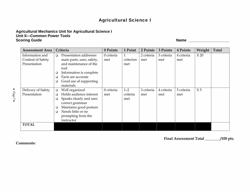
Agricultural Science I
Agricultural Mechanics Unit for Agricultural Science I Unit II—Common Power Tools Scoring Guide Name ___________________
Assessment Area Criteria 0 Points 1 Point 2 Points 3 Points 4 Points Weight Total Information and Content of Safety Presentation
Presentation addresses main parts, uses, safety, and maintenance of the tool
Information is complete Facts are accurate Good use of supporting
materials
0 criteria met
1 criterion met
2 criteria met
3 criteria met
4 criteria met
X 20
Delivery of Safety Presentation
Well organized Holds audience interest Speaks clearly and uses
correct grammar Maintains good posture Needs little or no
prompting from the instructor
0 criteria met
1–2 criteria met
3 criteria met
4 criteria met
5 criteria met
X 5
TOTAL
Final Assessment Total ________/100 pts.
Comments:
♦ Page 7 ♦

♦ Page 8 ♦
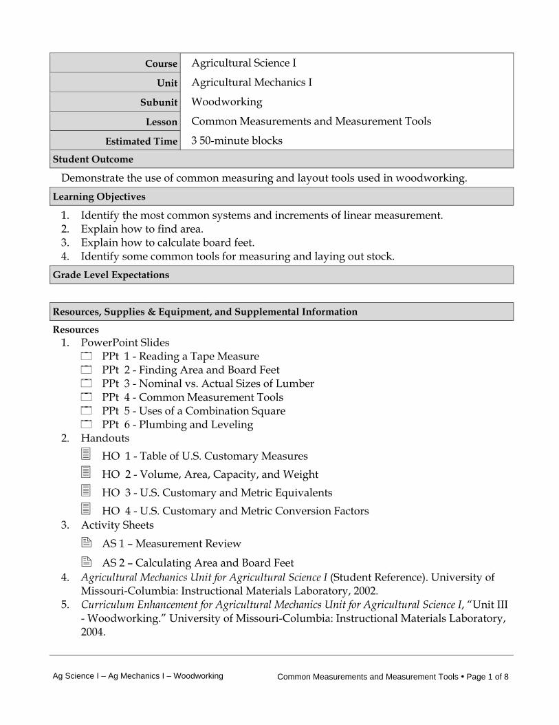
Ag Science I – Ag Mechanics I – Woodworking Common Measurements and Measurement Tools • Page 1 of 8
Course Agricultural Science I
Unit Agricultural Mechanics I
Subunit Woodworking
Lesson Common Measurements and Measurement Tools
Estimated Time 3 50-minute blocks Student Outcome
Demonstrate the use of common measuring and layout tools used in woodworking. Learning Objectives
1. Identify the most common systems and increments of linear measurement. 2. Explain how to find area. 3. Explain how to calculate board feet. 4. Identify some common tools for measuring and laying out stock.
Grade Level Expectations
Resources, Supplies & Equipment, and Supplemental Information
Resources 1. PowerPoint Slides
PPt 1 - Reading a Tape Measure PPt 2 - Finding Area and Board Feet PPt 3 - Nominal vs. Actual Sizes of Lumber PPt 4 - Common Measurement Tools PPt 5 - Uses of a Combination Square PPt 6 - Plumbing and Leveling
2. Handouts HO 1 - Table of U.S. Customary Measures HO 2 - Volume, Area, Capacity, and Weight HO 3 - U.S. Customary and Metric Equivalents HO 4 - U.S. Customary and Metric Conversion Factors
3. Activity Sheets
AS 1 – Measurement Review
AS 2 – Calculating Area and Board Feet 4. Agricultural Mechanics Unit for Agricultural Science I (Student Reference). University of
Missouri-Columbia: Instructional Materials Laboratory, 2002. 5. Curriculum Enhancement for Agricultural Mechanics Unit for Agricultural Science I, “Unit III
- Woodworking.” University of Missouri-Columbia: Instructional Materials Laboratory, 2004.
Ag Science I – Ag Mechanics I – Woodworking Common Measurements and Measurement Tools • Page 2 of 8
Supplies & Equipment See Unit III Activity for materials and equipment needed to complete the Unit Activity.
Supplemental Information 1. Internet Sites
Reading a Tape Measure. The Math Worksheet Site. Accessed September 12, 2007, from http://themathworksheetsite.com/read_tape.html.
Using and Maintaining a Tape Measure. Lowe’s. Accessed September 12, 2007, from http://www.lowes.com/lowes/lkn?action=howTo&p=Build/TapeMeasure.
Board Foot Calculator. University of Missouri Extension. Accessed September 12, 2007, from http://extension.missouri.edu/scripts/explore/G05506.asp.
Length Conversion. Unit Conversion. Accessed October 10, 2007, from http://www.unit-conversion.info/length.html.
2. Print Boyd, J. and C. Reynolds. Buildings for Small Acreages: Farm, Ranch and Recreation.
Danville, IL: Interstate Publishers, 1996. Burkybile, C., D. Johnson, J. Lee, and C. Shelhamer. Agricultural Power and
Technology. Danville, IL: Interstate Publishers, 2005. Phipps, L. and G. Miller. Introduction to Agricultural Mechanics. Upper Saddle River,
NJ: Prentice Hall Interstate, 2004. 3. Electronic Media
Tape Measure Video. Expert Tool Tips. Accessed October 10, 2007, from http://experttooltips.com/Tape_Measure_Video.shtml.
Ag Science I – Ag Mechanics I – Woodworking Common Measurements and Measurement Tools • Page 3 of 8
Instructor Directions Content Outline
Objective 1
Linear measurements include length, width, height, diameter (distance across the middle of round stock), and circumference (distance around round stock). Refer to PPt 1 and HO 1-4. Have students complete AS 1 to apply their skills at reading a ruler.
PPt 1 – Reading a Tape Measure
HO 1 - Table of U.S.
Customary Measures
HO 2 - Volume, Area, Capacity, and Weight
HO 3 - U.S. Customary
and Metric Equivalents
HO 4 - U.S. Customary and Metric Conversion
Identify the most common systems and increments of linear measurement.
U.S. customary (English) system 1. Yards 2. Feet 3. Inches 4. Fractions of an inch Metric 1. Meter 2. Centimeters 3. Millimeters
Interest Approach
Introduce students to the topic of layout tools by asking some of the following or similar questions: 1. Why is it important to be familiar with and use layout tools? 2. Why is it important that measurement tools be standarized? 3. What tool would be useful for measuring the height of the classroom wall? For
determining if it is plumb? 4. What measurements would students have to know to give the area of the classroom
floor? Communicate the Learning Objectives
1. Identify the most common systems and increments of linear measurement. 2. Explain how to find area. 3. Explain how to calculate board feet. 4. Identify some common tools for measuring and laying out stock.
Ag Science I – Ag Mechanics I – Woodworking Common Measurements and Measurement Tools • Page 4 of 8
Instructor Directions Content Outline
Factors
AS 1 – Measurement Review
Objective 2
Linear measurements can be used to determine how much surface area an object such as a piece of stock or a wall has. Refer to PPt 2.
PPt 2 – Finding Area and Board Feet
Explain how to find area. 1. Area measures surface. 2. To find the area of a wall, multiply length by height
(A=L x H). 3. To find the area of a floor or board, multiply length
by width (A=L x W). 4. Express answer in square units (sq ft, sq yd). 5. Multiply units of like measurement (ft with ft, yd
with yd). Objective 3
One of the most important measures in woodworking is board feet. It is important that students understand the nominal size of lumber versus the actual size when figuring board feet. Refer to PPt 3. Assign AS 2 to students for practice in calculating area and board feet.
PPt 3 – Nominal vs. Actual Sizes of Lumber
AS 2 – Calculating Area and Board Feet
Explain how to calculate board feet.
1. Board feet is a measure of volume (Volume = Length x Width x Height or Thickness).
2. A board foot is a piece of lumber 1 in. thick, 12 in. wide, and 12 in. long, or 144 cubic in.
3. Multiply T in. x W in. x L ft and divide by 12. 4. Boards less than 1 in. thick are figured as 1 in. 5. For boards over 1 in., use the nominal size for
figuring board feet. 6. Give answer in board feet (BF, bd ft). 7. Items like molding and dowel rod are measured in
linear feet (lin ft) rather than board feet.
Objective 4
Discuss the most common tools used for measurement and layout. Refer to PPt 1, 4, 5, and 6.
PPt 1 – Reading a Tape
Measure
PPt 4 – Common
Identify some common tools for measuring and laying out stock.
Folding rule 1. Generally 6 ft long 2. Extension rules have an inset rule for inside
measurements. Tape measure 1. A tape measure can be used for straight
measurements or for measuring around stock
Ag Science I – Ag Mechanics I – Woodworking Common Measurements and Measurement Tools • Page 5 of 8
Instructor Directions Content Outline
Measurement Tools
PPt 5 – Uses of a Combination Square
PPt 6 – Plumbing and
Leveling
(circumference). 2. A combination rule combines U.S. and metric
measurements and is useful for making quick, approximate conversions.
3. Avoid bending steel tapes. 4. Lightly oil steel tapes occasionally. Calipers 1. Measure diameter (distance across) 2. Inside calipers are used for interior measurements. 3. Outside calipers are for exterior measurements. Compass and dividers 1. Transfer dimensions 2. Inscribe arcs and circles Squares 1. Framing square
a. Used in framing b. Laying out stairs and rafters c. Determining whether materials or structures are
square 2. Combination square
a. Includes a rule b. Can be used as a marking gauge c. Laying out 45-degree angles d. Finding plumb and level e. Try square for inside/outside measurements
3. Try square a. Squaring b. Includes a rule c. Laying out 45-degree angles if handle beveled
4. Speed square a. Used for laying out stairs and rafters b. Used for measuring and marking miter cuts
T bevel 1. Laying out cuts 2. Transferring dimensions 3. Checking angles, bevels, and chamfers 4. Used as guide for drilling holes at an angle Marking gauge
Ag Science I – Ag Mechanics I – Woodworking Common Measurements and Measurement Tools • Page 6 of 8
Instructor Directions Content Outline
1. Scribing parallel lines 2. Marking depth 3. Useful for laying out dado or rabbet joints to be cut
with a chisel Chalk line 1. Laying out a straight line on a flat surface Plumb bob 1. Establish an exactly vertical line Level 1. Determining level or plumb
a. The level includes one or two small tubes of liquid, each containing an air bubble.
b. Level tube sits horizontally. c. Plumb tube sits vertically. d. When the bubble sits squarely between the two
marks on the tube, the surface is level or plumb. 2. Line level
a. Bubble tube that can be suspended on a string or line
b. Used to find level over longer distances Application:
AS 1 – Measurement Review
AS 2 – Calculating Area and Board Feet
Answers to AS 1 1. U.S. customary and metric 2. Students will indicate on illustration. 3. Students will indicate on illustration. 4. 50 mm or 5 cm 5. Students will indicate on illustration. 6. Students will indicate on illustration. 7. 1/16th 8. 1 1/4 in. 9. 2 ft, 3 in. Answers to AS 2 1. a. 18 ft x 15 ft = 270 sq ft 270 sq ft divided by 9 sq ft/sq yd = 30 sq yd of
carpeting
b. 18 ft x 15 ft = 270 sq ft 270 sq ft divided by 9 sq ft/sq yd = 30 sq yd of
carpet padding
Ag Science I – Ag Mechanics I – Woodworking Common Measurements and Measurement Tools • Page 7 of 8
Instructor Directions Content Outline
c. 15 ft x 8 ft = 120 sq ft for one wall 120 sq ft x 2 = 240 sq ft for second 15 ft x 8 ft wall 18 ft x 8 ft = 144 sq ft for one wall 144 sq ft x 2 = 288 sq ft for second 18 ft x 8 ft wall 240 sq ft + 288 sq ft = 528 sq ft total wall space Area of sheet of paneling: 4 ft x 8 ft = 32 sq ft 528 sq ft divided by 32 sq ft = 16.5 sheets of
paneling You must purchase 17 sheets to cover the whole
room. d. 17 x $10 = $170 for paneling 30 sq yd x $1.25 = $37.50 for carpet padding 30 sq yd x $7.50 = $225 for carpeting $225 + $37.50 + $170 = $432.50 total cost
2. a. 2 in. x 4 in. x 6 ft = 48, 48 divided by 12 = 4 bd ft
b. 4 bd ft x 8 = 32 bd ft total
3. 1 in. x 6 in. x 4 ft = 24, 24 divided by 12 = 2 bd ft 2 bd ft x 2 = 4 bd ft total
The thickness is rounded up from 3/4 to 1 in. to compute board feet.
Other activities 1. Identify various woodworking tasks around the shop
that require measurement and have students decide which measurement tools would be best for each task and why.
Closure/Summary Linear or straight-line measurements are used to determine dimensions such as length, width, diameter, and circumference. By using basic math, linear measurements can be used to find area and calculate board feet. Common tools for measurement and layout include folding rules and tape measures, squares, and levels. Squares are used to determine whether materials and structures are square. Levels are used to establish a horizontal or vertical reference point and lay out horizontal and vertical lines. Without these lines and reference points, floors will not be level, walls will not be plumb, and corners will not fit properly.
Ag Science I – Ag Mechanics I – Woodworking Common Measurements and Measurement Tools • Page 8 of 8
Instructor Directions Content Outline Evaluation: Quiz Answers:
1. d 2. a 3. c 4. b 5. a 6. a 7. b 8. b 9. c 10. b 11. a. U.S. customary
b. Metric 12. Students should provide any five of the following: a. Measuring/includes a rule b. Finding level c. Finding plumb d. As a marking gauge e. Laying out 45-degree angles f. As a try square 13. 16 bd ft 14. a. 1/16
b. 1/8 c. 3/16 d. 1/4 e. 5/16 f. 3/8 g. 7/16 h. 1/2 i. 9/16 j. 5/8 k. 11/16 l. 3/4 m. 13/16 n. 7/8 o. 15/16 p. 1 q. 1 3/8 r. 2 5/16
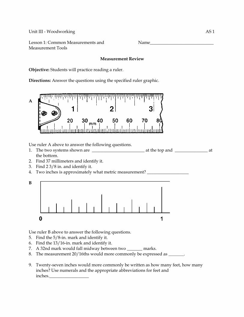
Unit III - Woodworking AS 1 Lesson 1: Common Measurements and Name_____________________________ Measurement Tools
Measurement Review Objective: Students will practice reading a ruler. Directions: Answer the questions using the specified ruler graphic.
A Use ruler A above to answer the following questions. 1. The two systems shown are ________________________ at the top and _______________ at
the bottom. 2. Find 37 millimeters and identify it. 3. Find 2 3/8 in. and identify it. 4. Two inches is approximately what metric measurement? ___________________ B Use ruler B above to answer the following questions. 5. Find the 5/8-in. mark and identify it. 6. Find the 13/16-in. mark and identify it. 7. A 32nd mark would fall midway between two _______ marks. 8. The measurement 20/16ths would more commonly be expressed as _______. 9. Twenty-seven inches would more commonly be written as how many feet, how many
inches? Use numerals and the appropriate abbreviations for feet and inches.__________________
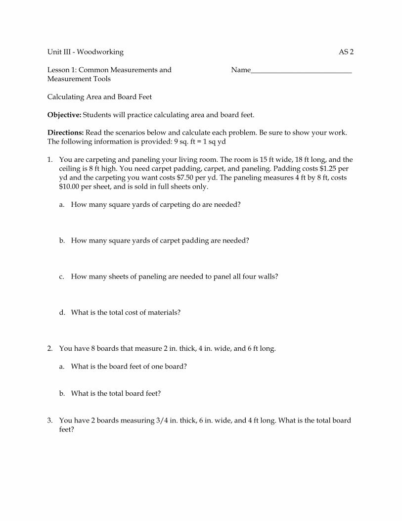
Unit III - Woodworking AS 2 Lesson 1: Common Measurements and Name____________________________ Measurement Tools Calculating Area and Board Feet Objective: Students will practice calculating area and board feet. Directions: Read the scenarios below and calculate each problem. Be sure to show your work. The following information is provided: 9 sq. ft = 1 sq yd 1. You are carpeting and paneling your living room. The room is 15 ft wide, 18 ft long, and the
ceiling is 8 ft high. You need carpet padding, carpet, and paneling. Padding costs $1.25 per yd and the carpeting you want costs $7.50 per yd. The paneling measures 4 ft by 8 ft, costs $10.00 per sheet, and is sold in full sheets only.
a. How many square yards of carpeting do are needed?
b. How many square yards of carpet padding are needed?
c. How many sheets of paneling are needed to panel all four walls? d. What is the total cost of materials?
2. You have 8 boards that measure 2 in. thick, 4 in. wide, and 6 ft long.
a. What is the board feet of one board? b. What is the total board feet?
3. You have 2 boards measuring 3/4 in. thick, 6 in. wide, and 4 ft long. What is the total board
feet?
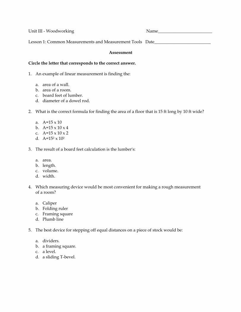
Unit III - Woodworking Name_________________________ Lesson 1: Common Measurements and Measurement Tools Date__________________________
Assessment Circle the letter that corresponds to the correct answer. 1. An example of linear measurement is finding the:
a. area of a wall. b. area of a room. c. board feet of lumber. d. diameter of a dowel rod.
2. What is the correct formula for finding the area of a floor that is 15 ft long by 10 ft wide?
a. A=15 x 10 b. A=15 x 10 x 4 c. A=15 x 10 x 2 d. A=152 x 102
3. The result of a board feet calculation is the lumber's:
a. area. b. length. c. volume. d. width.
4. Which measuring device would be most convenient for making a rough measurement of a room?
a. Caliper b. Folding ruler c. Framing square d. Plumb line
5. The best device for stepping off equal distances on a piece of stock would be:
a. dividers. b. a framing square. c. a level. d. a sliding T-bevel.
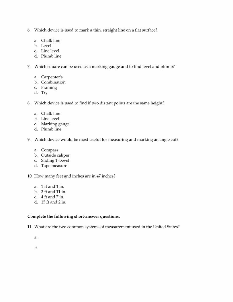
6. Which device is used to mark a thin, straight line on a flat surface?
a. Chalk line b. Level c. Line level d. Plumb line
7. Which square can be used as a marking gauge and to find level and plumb?
a. Carpenter's b. Combination c. Framing d. Try
8. Which device is used to find if two distant points are the same height?
a. Chalk line b. Line level c. Marking gauge d. Plumb line
9. Which device would be most useful for measuring and marking an angle cut?
a. Compass b. Outside caliper c. Sliding T-bevel d. Tape measure
10. How many feet and inches are in 47 inches?
a. 1 ft and 1 in. b. 3 ft and 11 in. c. 4 ft and 7 in. d. 15 ft and 2 in.
Complete the following short-answer questions. 11. What are the two common systems of measurement used in the United States?
a. b.

12. List five uses for a combination square. a. b. c. d. e.
13. How many board feet are there in a woodworking project requiring 8 boards that are 1 in. x 4 in. x 6 ft? 14. Fill in the blanks on the accompanying figure with the correct inch readings in the simplest
terms.
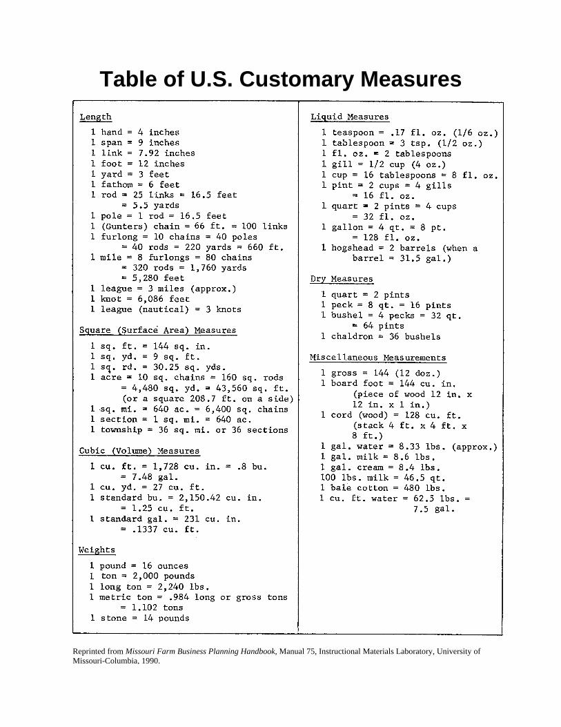
Table of U.S. Customary Measures
Reprinted from Missouri Farm Business Planning Handbook, Manual 75, Instructional Materials Laboratory, University of Missouri-Columbia, 1990.
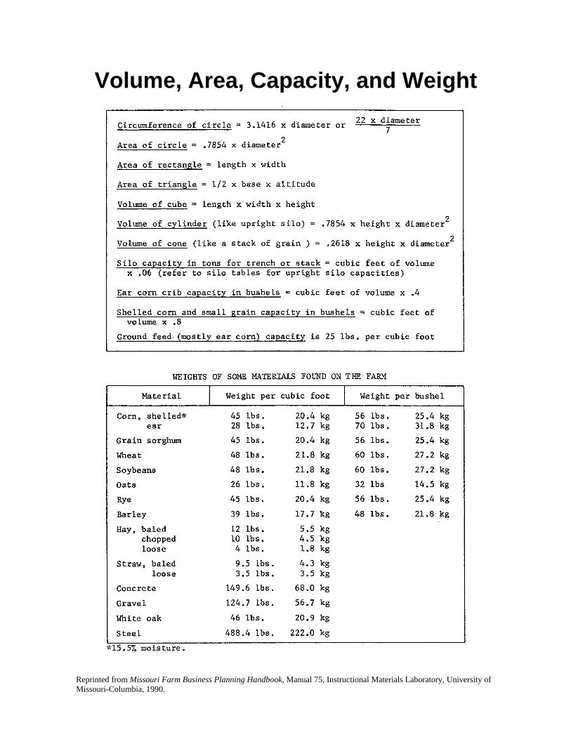
Volume, Area, Capacity, and Weight
Reprinted from Missouri Farm Business Planning Handbook, Manual 75, Instructional Materials Laboratory, University of Missouri-Columbia, 1990.
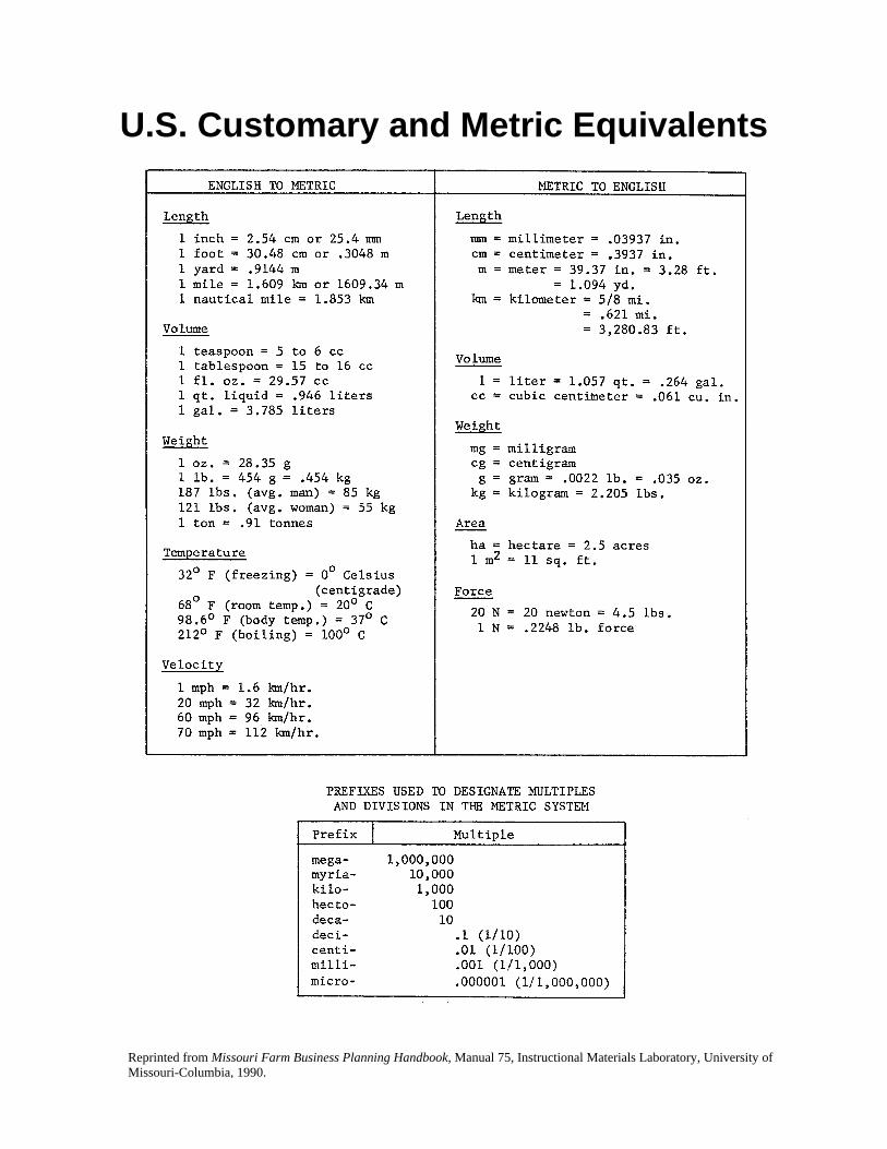
U.S. Customary and Metric Equivalents
Reprinted from Missouri Farm Business Planning Handbook, Manual 75, Instructional Materials Laboratory, University of Missouri-Columbia, 1990.
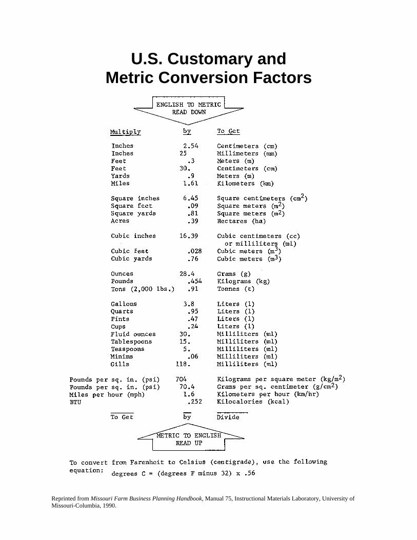
U.S. Customary and Metric Conversion Factors
Reprinted from Missouri Farm Business Planning Handbook, Manual 75, Instructional Materials Laboratory, University of Missouri-Columbia, 1990.
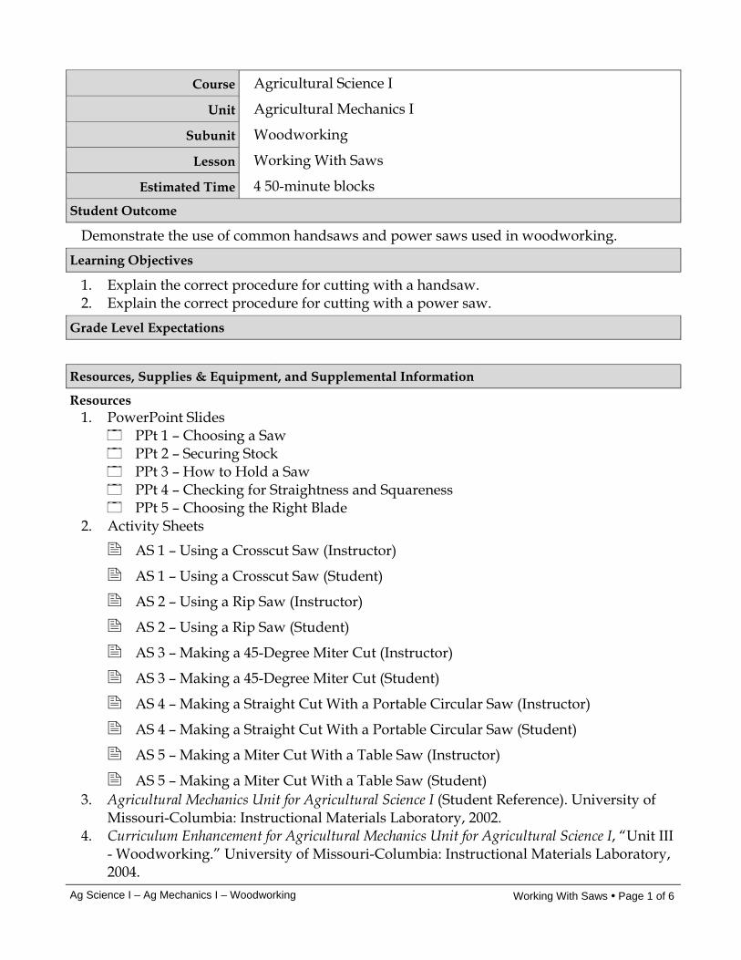
Ag Science I – Ag Mechanics I – Woodworking Working With Saws • Page 1 of 6
Course Agricultural Science I
Unit Agricultural Mechanics I
Subunit Woodworking
Lesson Working With Saws
Estimated Time 4 50-minute blocks Student Outcome
Demonstrate the use of common handsaws and power saws used in woodworking. Learning Objectives
1. Explain the correct procedure for cutting with a handsaw. 2. Explain the correct procedure for cutting with a power saw.
Grade Level Expectations
Resources, Supplies & Equipment, and Supplemental Information
Resources 1. PowerPoint Slides
PPt 1 – Choosing a Saw PPt 2 – Securing Stock PPt 3 – How to Hold a Saw PPt 4 – Checking for Straightness and Squareness PPt 5 – Choosing the Right Blade
2. Activity Sheets
AS 1 – Using a Crosscut Saw (Instructor)
AS 1 – Using a Crosscut Saw (Student)
AS 2 – Using a Rip Saw (Instructor)
AS 2 – Using a Rip Saw (Student)
AS 3 – Making a 45-Degree Miter Cut (Instructor)
AS 3 – Making a 45-Degree Miter Cut (Student)
AS 4 – Making a Straight Cut With a Portable Circular Saw (Instructor)
AS 4 – Making a Straight Cut With a Portable Circular Saw (Student)
AS 5 – Making a Miter Cut With a Table Saw (Instructor)
AS 5 – Making a Miter Cut With a Table Saw (Student) 3. Agricultural Mechanics Unit for Agricultural Science I (Student Reference). University of
Missouri-Columbia: Instructional Materials Laboratory, 2002. 4. Curriculum Enhancement for Agricultural Mechanics Unit for Agricultural Science I, “Unit III
- Woodworking.” University of Missouri-Columbia: Instructional Materials Laboratory, 2004.
Ag Science I – Ag Mechanics I – Woodworking Working With Saws • Page 2 of 6
Supplies & Equipment See AS 1 through AS 5 for materials and equipment needed to complete the Activity
Sheets. See Unit III Activity for materials and equipment needed to complete the Unit Activity.
Supplemental Information 1. Internet Sites
Sharpening a Hand Saw. Lost Crafts. Accessed September 14, 2007, from http://www.lostcrafts.com/Farm/Blacksmithing-22.html.
Using a Miter Box. Better Homes and Gardens. Accessed September 14, 2007, from http://www.bhg.com/bhg/story.jsp?storyid=/templatedata/bhg/step-by-step/data/hie_467.xml&catref=cat240050.
2. Print Burkybile, C., D. Johnson, J. Lee, and C. Shelhamer. Agricultural Power and
Technology. Danville, IL: Interstate Publishers, 2005. Phipps, L. and G. Miller. Introduction to Agricultural Mechanics. Upper Saddle River,
NJ: Prentice Hall Interstate, 2004. 3. Electronic Media
Circular Saw Tips Video. Expert Tool Tips. Accessed October 10, 2007, from http://experttooltips.com/Circular_Saw_Tips_Video.shtml.
Smartflix offers a line of videos related to woodworking that can be rented from their Web site. Accessed September 12, 2007, from http://smartflix.com/store/category/118/Woodworking.
Ag Science I – Ag Mechanics I – Woodworking Working With Saws • Page 3 of 6
Instructor Directions Content Outline
Objective 1
Before beginning, review basic cutting procedures as needed and give examples of their application. For example, crosscutting is cutting across the grain of wood, and cutting a board to length by cutting the end off is an example of a crosscutting procedure. When students have reviewed handsaw cutting procedures, use the instructor version of AS 1-3 to demonstrate the correct way to make crosscuts, rip cuts, and miter cuts with handsaws. The student versions of the activity sheets should be assigned to evaluate student competency of these cuts. Refer to PPt 1-4.
AS 1 – Using a Crosscut Saw
AS 2 – Using a Rip Saw
AS 3 – Making a 45-Degree Miter Cut
PPt 1– Choosing a Saw
Explain the correct procedure for cutting with a handsaw.
Choose appropriate saw. 1. Number of teeth
a. Fewer teeth per inch for rougher cutting b. More teeth per inch for finer cuts
2. Design of teeth a. Pointed, knife-like teeth for cutting across the
grain, or crosscutting b. Chisel-shaped teeth for cutting with the grain, or
ripping Observe basic safety procedures. Everyone using tools or in the work area should wear appropriate protective eyewear. Mark stock using a fine mark for accuracy. Secure stock. 1. Small pieces can be held in a vise. 2. Larger work should be held in place with the cutting
mark over the end of the work surface. 3. A miter box can be used for precise miter cuts. Use index finger of sawing hand to guide handle. Set blade on waste side of mark. Draw saw back to start the cut, using the nail of the noncutting thumb as guide, taking care not to cut the thumb. When cut is started, move the thumb out of the way.
Interest Approach
1. Have students identify the various hand and power saws in the shop and the type of work for which they are used.
2. Identify major parts of power saws in the shop and review relevant safety information.
Communicate the Learning Objectives
1. Explain the correct procedure for cutting with a handsaw. 2. Explain the correct procedure for cutting with a power saw.
Ag Science I – Ag Mechanics I – Woodworking Working With Saws • Page 4 of 6
Instructor Directions Content Outline
PPt 2 – Securing Stock
PPt 3 – How to Hold a Saw
PPt 4 – Checking for Straightness and Squareness
Keep eyes on same vertical plane as the cut. Cut with long, even strokes. 1. Keep the saw at a 45-degree angle to the work when
crosscutting. 2. Keep the saw at a 60-degree angle to the work when
ripping. Use slow strokes with no pressure to finish the cut, supporting the waste piece so it doesn’t splinter the edge or bind the blade. Check cut with a square if squareness is important. Observe safety and cleanup procedures. Saw should be returned to its assigned place.
Objective 2
Crosscutting, ripping, and making miter cuts can be performed by a number of handheld, bench-mounted, and floor-mounted saws. General shop safety procedures were discussed in Unit I and some specific safety considerations for particular power saws were discussed in Unit II Lesson 1. Review or supplement these discussions as needed, based on student mastery and tools the students will be using. Additional power saw considerations are listed below. Refer to PPt 5. When students have reviewed power saw cutting procedures, the instructor versions of AS 4 and 5 should be used to demonstrate the correct way to make basic cuts using a portable circular saw and a table saw. The student version of the activity sheets should be assigned
Explain the correct procedure for cutting with a power saw. Get permission from instructor. Choose the right blade. 1. For the material 2. For the cut Unplug the tool for all inspections and adjustments. Inspect the blade and saw. Do not use broken or damaged equipment. Report damage to instructor. Be sure all guards and the blade are installed correctly for the saw being used. Remember that even though they are similar, the blade of a portable circular saw and the blade of a table saw are installed the opposite way. Think through the procedure before beginning. 1. Is a clamp, push stick, or other device needed? 2. Is an assistant needed? 3. How should the stock be positioned to avoid
splintering the better side? Follow all safety and proper use procedures. 1. Be sure the tool is properly grounded and the cord
Ag Science I – Ag Mechanics I – Woodworking Working With Saws • Page 5 of 6
Instructor Directions Content Outline
to evaluate student competency of these cuts.
PPt 5 – Choosing the Right Blade
AS 4 – Making a Straight Cut With a Portable Circular Saw
AS 5 – Making a Miter Cut With a Table Saw
will not get tangled in the work. 2. Keep hands clear of the cutting line. 3. If a tool is not functioning properly or doesn’t sound
right, turn it off immediately and report it to the instructor.
4. When finished, turn off the power and stay with the tool until it has come to a complete stop.
Clean up dust and scraps following shop procedures. Materials and equipment should be returned to their assigned place.
Application:
AS 1 – Using a Crosscut Saw
AS 2 – Using a Rip Saw
AS 3 – Making a 45-Degree Miter Cut
AS 4 – Making a Straight Cut with a Portable Circular Saw
AS 5 – Making a Miter Cut With a Table Saw
AS 1 – AS 5 Results will vary.
Closure/Summary Factors to consider when planning to use a handsaw include the number and design of the teeth. The right saw should be chosen for the job, keeping in mind the material and the type of cut. With a handsaw, the cut is made in long, even strokes, with the saw at a 45-degree angle for crosscutting and at a 60-degree angle for rip cutting. When a power saw is used, it is important to assess the job beforehand to determine if a clamp, push stick or other device is needed, if assistance will be needed, and how to position the stock to avoid splintering the better side.
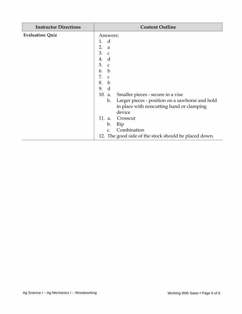
Ag Science I – Ag Mechanics I – Woodworking Working With Saws • Page 6 of 6
Instructor Directions Content Outline Evaluation: Quiz Answers:
1. d 2. a 3. c 4. d 5. c 6. b 7. c 8. b 9. d 10. a. Smaller pieces - secure in a vise
b. Larger pieces - position on a sawhorse and hold in place with noncutting hand or clamping device
11. a. Crosscut b. Rip c. Combination
12. The good side of the stock should be placed down.

Unit III - Woodworking AS 1 (Instructor) Lesson 2: Working With Saws
Using a Crosscut Saw Objective: Students will observe how to use a crosscut saw safely and correctly. Directions: Use a crosscut saw to cut a piece of lumber to a desired length. Materials and Equipment: Crosscut saw Straightedge Square Pencil Safety glasses or goggles * Scrap lumber, length to be determined by instructor * Everyone participating in or observing the demonstration should wear appropriate protective eyewear. Procedure: 1. Use the straightedge and pencil to lay out a fine cutting mark. 2. Secure the stock in place with the cutting mark over the end of the work surface. 3. Use the index finger of the sawing hand to guide the saw handle. 4. Set the blade on the waste side of the cutting mark. 5. Draw the saw back to start the cut, using the nail of the noncutting thumb as guide, taking
care not to cut the thumb. When the cut is started, move the thumb out of the way. 6. Keep eyes on the same vertical plane as the cut. 7. Cut with long, even strokes, keeping the saw at a 45-degree angle to the work. 8. Use slow strokes with no pressure to finish the cut, supporting the waste piece so it doesn’t
splinter the edge or bind the blade. 9. Check the cut for square. 10. Observe safety and cleanup procedures. 11. Assign AS 1 to be performed by students.
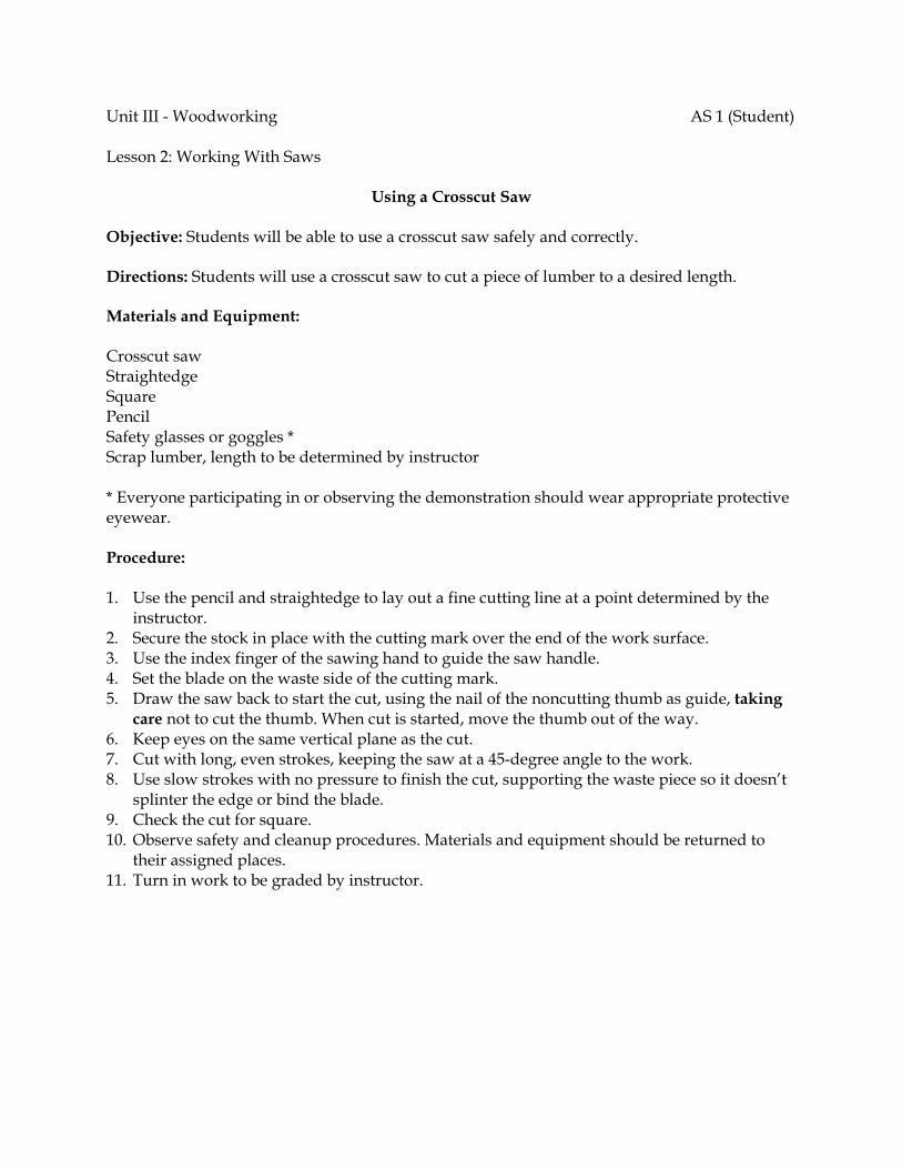
Unit III - Woodworking AS 1 (Student) Lesson 2: Working With Saws
Using a Crosscut Saw Objective: Students will be able to use a crosscut saw safely and correctly. Directions: Students will use a crosscut saw to cut a piece of lumber to a desired length. Materials and Equipment: Crosscut saw Straightedge Square Pencil Safety glasses or goggles * Scrap lumber, length to be determined by instructor * Everyone participating in or observing the demonstration should wear appropriate protective eyewear. Procedure: 1. Use the pencil and straightedge to lay out a fine cutting line at a point determined by the
instructor. 2. Secure the stock in place with the cutting mark over the end of the work surface. 3. Use the index finger of the sawing hand to guide the saw handle. 4. Set the blade on the waste side of the cutting mark. 5. Draw the saw back to start the cut, using the nail of the noncutting thumb as guide, taking
care not to cut the thumb. When cut is started, move the thumb out of the way. 6. Keep eyes on the same vertical plane as the cut. 7. Cut with long, even strokes, keeping the saw at a 45-degree angle to the work. 8. Use slow strokes with no pressure to finish the cut, supporting the waste piece so it doesn’t
splinter the edge or bind the blade. 9. Check the cut for square. 10. Observe safety and cleanup procedures. Materials and equipment should be returned to
their assigned places. 11. Turn in work to be graded by instructor.
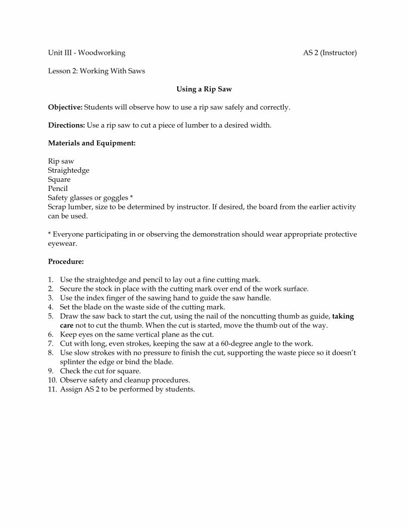
Unit III - Woodworking AS 2 (Instructor) Lesson 2: Working With Saws
Using a Rip Saw Objective: Students will observe how to use a rip saw safely and correctly. Directions: Use a rip saw to cut a piece of lumber to a desired width. Materials and Equipment: Rip saw Straightedge Square Pencil Safety glasses or goggles * Scrap lumber, size to be determined by instructor. If desired, the board from the earlier activity can be used. * Everyone participating in or observing the demonstration should wear appropriate protective eyewear. Procedure: 1. Use the straightedge and pencil to lay out a fine cutting mark. 2. Secure the stock in place with the cutting mark over end of the work surface. 3. Use the index finger of the sawing hand to guide the saw handle. 4. Set the blade on the waste side of the cutting mark. 5. Draw the saw back to start the cut, using the nail of the noncutting thumb as guide, taking
care not to cut the thumb. When the cut is started, move the thumb out of the way. 6. Keep eyes on the same vertical plane as the cut. 7. Cut with long, even strokes, keeping the saw at a 60-degree angle to the work. 8. Use slow strokes with no pressure to finish the cut, supporting the waste piece so it doesn’t
splinter the edge or bind the blade. 9. Check the cut for square. 10. Observe safety and cleanup procedures. 11. Assign AS 2 to be performed by students.
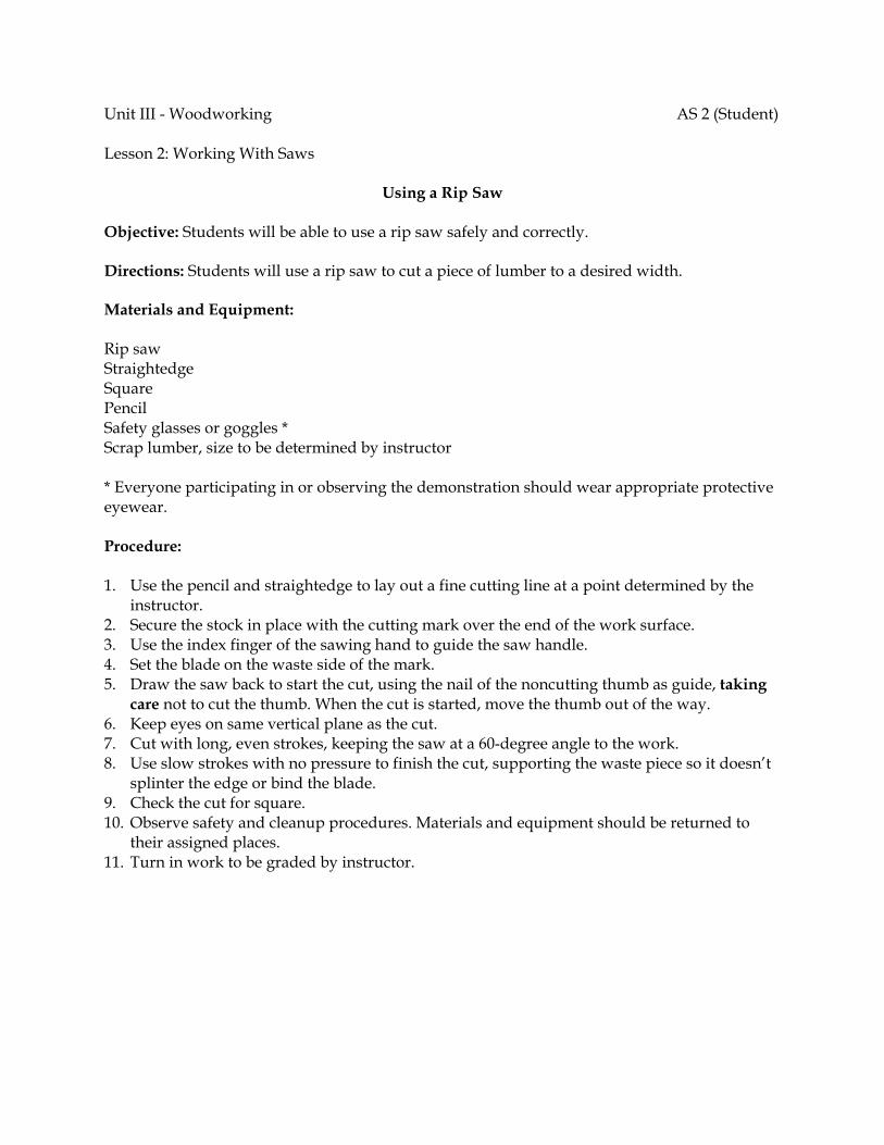
Unit III - Woodworking AS 2 (Student) Lesson 2: Working With Saws
Using a Rip Saw Objective: Students will be able to use a rip saw safely and correctly. Directions: Students will use a rip saw to cut a piece of lumber to a desired width. Materials and Equipment: Rip saw Straightedge Square Pencil Safety glasses or goggles * Scrap lumber, size to be determined by instructor * Everyone participating in or observing the demonstration should wear appropriate protective eyewear. Procedure: 1. Use the pencil and straightedge to lay out a fine cutting line at a point determined by the
instructor. 2. Secure the stock in place with the cutting mark over the end of the work surface. 3. Use the index finger of the sawing hand to guide the saw handle. 4. Set the blade on the waste side of the mark. 5. Draw the saw back to start the cut, using the nail of the noncutting thumb as guide, taking
care not to cut the thumb. When the cut is started, move the thumb out of the way. 6. Keep eyes on same vertical plane as the cut. 7. Cut with long, even strokes, keeping the saw at a 60-degree angle to the work. 8. Use slow strokes with no pressure to finish the cut, supporting the waste piece so it doesn’t
splinter the edge or bind the blade. 9. Check the cut for square. 10. Observe safety and cleanup procedures. Materials and equipment should be returned to
their assigned places. 11. Turn in work to be graded by instructor.
Unit III - Woodworking AS 3 (Instructor) Lesson 2: Working With Saws
Making a 45-Degree Miter Cut Objective: Students will observe how to use a miter box to make a miter cut safely and correctly. Directions: Use a miter box saw to make a mitered corner. Materials and Equipment: Miter box saw Miter box Combination square Pencil Safety glasses or goggles * 2 pieces of scrap lumber, size to be determined by instructor. If desired, the boards from the earlier activity can be used. * Everyone participating in or observing the demonstration should wear appropriate protective eyewear. Procedure: 1. Use the square and pencil to lay out a 45-degree cutting line. 2. Set the miter box for a 45-degree angle cut. 3. Secure the stock against the back of the miter box. 4. Use the index finger of the sawing hand to guide the saw handle. 5. Set the blade on the waste side of the cutting mark. 6. Draw the saw back to start the cut. 7. Cut with long, even strokes. 8. Use slow strokes with no pressure to finish the cut, supporting the waste piece so it doesn’t
splinter the edge or bind the blade, if needed. 9. Repeat the procedure with the other board. 10. Check the cuts using the combination square. 11. Place the two boards together to make a 90-degree angle. 12. Check the assembled angle for square. 13. Observe safety and cleanup procedures. 14. Assign AS 3 to be performed by students.
Unit III - Woodworking AS 3 (Student) Lesson 2: Working With Saws
Making a 45-Degree Miter Cut Objective: Students will be able to use a miter box to make a miter cut safely and correctly. Directions: Students will use a miter box saw to make a mitered corner. Materials and Equipment: Miter box saw Miter box Combination square Pencil Safety glasses or goggles * 2 pieces of scrap lumber, size to be determined by instructor * Everyone participating in or observing the demonstration should wear appropriate protective eyewear. Procedure: 1. Use the square and pencil to lay out a 45-degree cutting line at a point determined by the
instructor. 2. Set the miter box for a 45-degree angle cut. 3. Secure the stock against the back of the miter box. 4. Use the index finger of the sawing hand to guide the handle. 5. Set the blade on the waste side of the mark. 6. Draw the saw back to start the cut. 7. Cut with long, even strokes. 8. Use slow strokes with no pressure to finish the cut, supporting the waste piece so it doesn’t
splinter the edge or bind the blade, if needed. 9. Repeat the procedure with the other board. 10. Check the cuts using the combination square. 11. Place the two boards together to make a 90-degree angle. 12. Check the assembled angle for square. 13. Observe safety and cleanup procedures. Materials and equipment should be returned to
their assigned places. 14. Turn in work to be graded by instructor.
Unit III - Woodworking AS 4 (Instructor) Lesson 2: Working With Saws
Making a Straight Cut With a Portable Circular Saw Objective: Students will observe how to use a portable circular saw to make a cut safely and correctly. Instruction is given for crosscutting with the circular saw. The activity can be altered or supplemented for rip cutting or other cutting operations at the instructor's discretion. Directions: Use a portable circular saw for crosscutting. Materials and Equipment: Portable circular saw Crosscut or combination blade Straightedge Square Pencil Safety glasses or goggles * Piece of scrap lumber, size to be determined by instructor * Everyone participating in or observing the demonstration should wear appropriate protective eyewear. Procedure: 1. Make sure the saw is unplugged. 2. Inspect the blade and saw for damage. 3. If needed, install the blade following the manufacturer-recommended procedure for the
saw, using all washers and bushings correctly. 4. Use the straightedge and pencil to lay out a fine cutting mark. 5. Secure or support the work so that it will not bind the blade while sawing. 6. Adjust the blade for the depth of the stock, plus 1/4 in. 7. Plug the saw in. Be sure the cord is clear of the work 8. With its base on the board, back the saw away slightly and turn it on. The saw should be at
full speed before cutting. 9. Keep hands clear of the cutting line. 10. Watch the line ahead of the saw, keeping the saw’s reference mark on the line. If the saw
veers off its mark, stop it, pull it back, and start over to avoid binding the blade. 11. Release the switch to stop the saw and wait until it has come to a complete stop. 12. Check the cut for square. 13. Observe safety and cleanup procedures. 14. Assign AS 4 to be performed by students.
Unit III - Woodworking AS 4 (Student) Lesson 2: Working With Saws
Making a Straight Cut With a Portable Circular Saw Objective: Students will use a portable circular saw to make a cut safely and correctly. Directions: Students will use a portable circular saw to make a cut. Materials and Equipment: Portable circular saw Appropriate saw blade Straightedge Square Pencil Safety glasses or goggles * Piece of scrap lumber, size to be determined by instructor * Everyone participating in or observing the demonstration should wear appropriate protective eyewear. Procedure: 1. Make sure the saw is unplugged. 2. Inspect the blade and saw for damage. 3. If needed, install the blade following the manufacturer-recommended procedure for the
saw, using all washers and bushings correctly. 4. Use the straightedge and pencil to lay out a fine cutting mark according to the instructor’s
directions. 5. Secure or support work so that it will not bind the blade while sawing. 6. Adjust the blade for the depth of the stock, plus 1/4 in. 7. Plug the saw in. Be sure the cord is clear of the work 8. With its base on the board, back the saw away slightly and turn it on. The saw should be at
full speed before cutting. 9. Keep hands clear of the cutting line. 10. Watch the line ahead of the saw, keeping the saw’s reference mark on the line. If the saw
veers off its mark, stop it, pull it back, and start over to avoid binding the blade. 11. Release the switch to stop the saw and wait until it has come to a complete stop. 12. Check the cut for square. 13. Observe safety and cleanup procedures. Materials and equipment should be returned to
their assigned places. 14. Turn in work to be graded by instructor.
Unit III - Woodworking AS 5 (Instructor) Lesson 2: Working With Saws
Making a Miter Cut With a Table Saw Objective: Students will observe how to use a table saw to make a 45-degree miter cut safely and correctly. Instruction is given for cutting with a table saw. The activity can be altered or supplemented at the instructor's discretion. Directions: Use a table saw to make a 45-degree miter cut. Materials and Equipment: Table saw Crosscut or combination blade Combination square Pencil Safety glasses or goggles * Piece of scrap lumber, size to be determined by instructor * Everyone participating in or observing the demonstration should wear appropriate protective eyewear. Procedure: 1. Use the square and pencil to lay out a 45-degree cutting line. 2. Make sure the saw is unplugged. 3. Inspect the blade and saw for damage. 4. If needed, install the blade following the manufacturer-recommended procedure. The teeth
of the blade should point toward the direction of rotation. 5. Make sure the guard assembly is in place. Only a few cuts require the removal of the guard.
For these cuts, use other safety measures. 6. Adjust the saw so that the teeth of the blade clear the top of the board by 1/4 in. 7. Remove the rip fence or move it out of the way. 8. Make sure the miter gauge is working freely and will clear the blade. 9. Adjust the miter gauge for the desired angle. Miter gauges can be set in the open or closed
position. Whenever possible, use the closed position for flat miter cuts. 10. Stand to the side of the blade when preparing to use the saw. Do not reach across it. 11. With the stock on the table, turn the saw on. The saw should be at full speed before cutting.
Hold the work firmly against the miter gauge. 12. Keep hands at least 6 in. from the blade. 13. Turn off the saw and wait until it has come to a complete stop. 14. Check the cut with the square. 15. Observe safety and cleanup procedures. 16. Assign AS 5 to be performed by students.
Unit III - Woodworking AS 5 (Student) Lesson 2: Working With Saws
Making a Miter Cut With a Table Saw Objective: Students will use a table saw to make a 45-degree miter cut safely and correctly. Directions: Students will use a table saw to make a 45-degree miter cut. Materials and Equipment: Table saw Crosscut or combination blade Combination square Pencil Safety glasses or goggles * Piece of scrap lumber, size to be determined by instructor * Everyone participating in or observing the demonstration should wear appropriate protective eyewear. Procedure: 1. Use the square and pencil to lay out a 45 degree cutting line. 2. Make sure the saw is unplugged. 3. Inspect the blade and saw for damage. 4. If needed, install the blade following the manufacturer-recommended procedure. The teeth
of the blade should point toward the direction of rotation. 5. Make sure the guard assembly is in place. Only a few cuts require the removal of the guard.
For these cuts, use other safety measures, according to the instructor’s direction. 6. Adjust the saw so that the teeth of the blade clear the top of the board by 1/4 in. 7. Remove the rip fence or move it out of the way. 8. Make sure the miter gauge is working freely and will clear the blade. 9. Adjust the miter gauge for the desired angle. Miter gauges can be set in the open or closed
position. Whenever possible, use the closed position for flat miter cuts. 10. Stand to the side of the blade when preparing to use the saw. Do not reach across it. 11. With the stock on the table, turn the saw on. The saw should be at full speed before cutting.
Hold the work firmly against the miter gauge. CAUTION: Always use the miter gauge when crosscutting or the rip fence when ripping.
Do not use the table saw free hand. 12. Keep hands at least 6 in. from the blade. 13. Turn off the saw and wait until it has come to a complete stop. 14. Check the cut with the square. 15. Observe safety and cleanup procedures. Materials and equipment should be returned to
their assigned places. 16. Turn in work to be graded by instructor.

Unit III - Woodworking Name_________________________ Lesson 2: Working With Saws Date__________________________
Assessment Circle the letter that corresponds to the correct answer. 1. Which point blade is best for making a fine cut with a handsaw?
a. 5 1/2 b. 7 c. 10 d. 11
2. How many tooth points per inch does a ripsaw commonly have?
a. 5 1/2 b. 7 c. 9 1/2 d. 11
3. Which instrument is commonly used for making a layout on wood?
a. Center punch b. Scratch awl c. Sharp pencil d. Soapstone
4. When using a handsaw or power saw, what type of safety gear should be worn by the
operator and others in the work area?
a. Cap b. Insulated gloves c. Leather apron d. Safety goggles
5. When starting a cut, how is the blade of a saw positioned in relation to the cutting mark?
a. In the center of the mark b. At a slight angle to the mark c. On the waste side of the mark d. On the nonwaste side of the mark
6. The cut a saw makes is called the:
a. groove. b. kerf. c. rabbet. d. rip.
7. At what degree angle should a handsaw be held when crosscutting?
a. 75 b. 60 c. 45 d. 30
8. A combination blade for a circular saw can be used for both:
a. crosscutting and cutting curves. b. crosscutting and ripping. c. shaving the surface and cutting curves. d. shaving the surface and ripping.
9. Which step is correct in preparing to cut with a portable circular saw or table saw?
a. Have a push stick ready to use for longer stock. b. Plug the saw in and then inspect it for damage. c. Use a center punch to lay out fine cutting marks. d. Ensure the blade is at full speed before cutting.
Complete the following short-answer questions. 10. Explain how smaller and larger pieces of stock should be secured before cutting with a
handsaw.
a. Smaller pieces - b. Larger pieces -
11. What are three common circular saw blades?
a. b. c.

12. How should stock be positioned to avoid splintering the good side when using a portable circular saw?
Ag Science I – Ag Mechanics I – Woodworking Working With Drills • Page 1 of 6
Course Agricultural Science I
Unit Agricultural Mechanics I
Subunit Woodworking
Lesson Working With Drills
Estimated Time 90 minutes or 2 50-minute blocks Student Outcome
Demonstrate the use of common handheld tools used to bore and drill in wood. Learning Objectives
1. Identify common types of bits used in woodworking and how they are used. 2. Explain the correct procedure for using a handheld drill. 3. Explain how to avoid splitting wood when drilling through a board. 4. Explain how to keep the drill square with the surface of the stock.
Grade Level Expectations
Resources, Supplies & Equipment, and Supplemental Information
Resources 1. PowerPoint Slides
PPt 1 – Common Drill Bits PPt 2 – Prevention of Splitting PPt 3 – Keeping the Drill Vertical to the Stock
2. Activity Sheets
AS 1 – Using a Brace (Instructor)
AS 1 – Using a Brace (Student)
AS 2 – Using a Portable Drill (Instructor)
AS 2 – Using a Portable Drill (Student) 3. Agricultural Mechanics Unit for Agricultural Science I (Student Reference). University of
Missouri-Columbia: Instructional Materials Laboratory, 2002. 4. Curriculum Enhancement for Agricultural Mechanics Unit for Agricultural Science I, “Unit III
- Woodworking.” University of Missouri-Columbia: Instructional Materials Laboratory, 2004.
Supplies & Equipment See AS 1 and AS 2 for materials and equipment needed to complete the Activity Sheets. See Unit III Activity for materials and equipment needed to complete the Unit Activity.
Supplemental Information 1. Internet Sites
Handheld Drill. Occupational Safety and Health Administration. U. S. Department of Labor. Accessed September 14, 2007, from http://www.osha.gov/SLTC/etools/woodworking/production_handhelddrills.html.

Ag Science I – Ag Mechanics I – Woodworking Working With Drills • Page 2 of 6
Occupational Safety: Portable Power Tools. Florida State University. Accessed September 14, 2007, from http://www.safety.fsu.edu/powertoolsmanual.html.
2. Print Burkybile, C., D. Johnson, J. Lee, and C. Shelhamer. Agricultural Power and
Technology. Danville, IL: Interstate Publishers, 2005. Phipps, L. and G. Miller. Introduction to Agricultural Mechanics. Upper Saddle River,
NJ: Prentice Hall Interstate, 2004. 3. Electronic Media
Smartflix offers a line of videos related to woodworking that can be rented from their Web site. Accessed September 12, 2007, from http://smartflix.com/store/category/118/Woodworking.
Ag Science I – Ag Mechanics I – Woodworking Working With Drills • Page 3 of 6
Instructor Directions Content Outline
Objective 1
As discussed in Unit I, there are many different bits designed for special use, but each has one of two types of shank (end of the bit). A bit has either a round (straight) shank or a square shank, which is a tapered square tang. Square-shank bits are used with the brace; round-shank bits are used in hand drills and portable electric drills. Some common bits and their uses are discussed at right. Refer to PPt 1.
PPt 1– Common Drill Bits
Identify common types of bits used in woodworking and how they are used.
Auger bits 1. Used for boring (making holes 1/4 in. and larger) 2. Usually sized by a number that refers to the bit’s
measurement in 16ths of an inch (a 4 would equal 4/16 or 1/4 in.).
Twist drills or twist drill bits 1. Round shank bits used in hand drills and portable
electric drills 2. Similar bits called “bit-stock drills” have square
shanks for use with brace 3. Available for use on a variety of materials Expansive bits 1. An adjustable auger bit 2. Can be used in place of several auger bits by
adjusting the cutter with the setscrew Forstner bits 1. Make a very smooth, flat-bottomed hole 2. Good for making blind holes that do not go through
work 3. Also good for enlarging existing holes
Interest Approach
Have students identify the drills in the shop and their major parts. Discuss relevant safety information and ask the following, or similar, questions to guide the discusion. 1. What kind of shank is used in a brace? In a portable electric drill? 2. How is the size of a brace determined? Of a portable electric drill? 3. How would you ensure that you were drilling perpendicular (at a 90 degree angle) to
the wood? 4. How would you avoid splitting wood with the drill?
Communicate the Learning Objectives
1. Identify common types of bits used in woodworking and how they are used. 2. Explain the correct procedure for using a handheld drill. 3. Explain how to avoid splitting wood when drilling through a board. 4. Explain how to keep the drill square with the surface of the stock.
Ag Science I – Ag Mechanics I – Woodworking Working With Drills • Page 4 of 6
Instructor Directions Content Outline
Spade or speed bits 1. Good for counterboring 2. Can be ground to make different shapes
Objective 2
General shop safety procedures and some specific use and safety considerations for particular drills were discussed in Unit I Lesson 1. Additional considerations for using boring and drilling tools are listed at right. Review or supplement these discussions as needed, based on student mastery and tools the students will be using.
Explain the correct procedure for using a handheld drill. Choose the right bit for the job. 1. Use square-shank bits with the brace. 2. Use round-shank bits with the hand drill and
portable electric drill. 3. Use the right bit for the material being worked on and
the type of hole to be made. Observe basic safety procedures. Everyone using tools or in the work area should wear appropriate protective eyewear. If using an electric drill, disconnect from power source and make any necessary inspections and adjustments. Secure the bit in the chuck. 1. For the hand drill and brace, tighten by hand. 2. For keyed chucks
a. Secure the bit by tightening around the chuck, using the chuck key in each hole.
b. Remove the chuck key when finished. If needed, use a punch or awl to make a starter hole to keep the bit from slipping. Secure the stock in a vise or other device to avoid movement. Check to see that the bit is centered. With an electric drill, plug it in and turn on the switch briefly, with the drill not touching the stock, and observe its rotation. Locate the bit in the mark. With a portable electric drill, do this with the power off. Hold the drill firmly and work with even pressure. Keep the drill at the correct angle to avoid binding the bit.
Ag Science I – Ag Mechanics I – Woodworking Working With Drills • Page 5 of 6
Instructor Directions Content Outline
Reduce pressure when breaking through the material. Additional information on how to avoid splintering wood appears in the next objective. Remove the bit from the chuck when finished. Clean up dust and scraps following shop procedures. Materials and equipment should be returned to their assigned place.
Objective 3
Methods for not splitting wood are discussed at right. Refer to PPt 2.
PPt 2 – Prevention of
Splitting
Explain how to avoid splitting wood when drilling through a board.
To avoid splitting the back, use one of two methods. 1. Remove the bit when it begins to break through the
stock. Insert the bit on the other side and finish boring the hole.
2. Clamp a piece of scrap to the bottom of the stock. Be careful not to mar the face of a good board using this method.
To avoid splitting the sides of narrow stock, put it in a clamp.
Objective 4
When students have reviewed these procedures, the instructor version of AS 1 and 2 should be used to demonstrate the correct way to use handheld drills. The student version of these activities should be assigned to evaluate student competency of these activities. Refer to PPt 3.
AS 1 – Using a Brace
AS 2 – Using a Portable Drill
Explain how to keep the drill square with the surface of the stock.
Use try squares to align the drill. Sight the drill from two different angles.
Ag Science I – Ag Mechanics I – Woodworking Working With Drills • Page 6 of 6
Instructor Directions Content Outline
PPt 3 – Keeping the Drill Vertical to the Stock
Application:
AS 1 – Using a Brace
AS 2 – Using a Portable Drill
AS 1 – AS 2 Results will vary.
Closure/Summary Common types of drill bits include auger bits, twist drill bits, Forstner bits, and spade or speed bits. Important safety considerations when using a drill include making sure the bit is tight in the chuck, securing the stock in a vise or other device to prevent movement, and keeping the drill at the correct angle to avoid binding the bit. A technique to prevent splitting of wood is to remove the bit from the hole just as it begins to break through the stock and then insert the bit on the other side to finish the hole.
Evaluation: Quiz Answers: 1. a 2. b 3. b 4. c 5. d 6. c 7. b 8. Safety glasses or goggles 9. a. Remove the bit when the point begins to break
through the stock. Then insert the bit on the other side of the stock and finish boring the hole. b. Clamp a piece of scrap wood under the stock. The
scrap stock supports the edges of the hole and as the bit bores into the scrap, it helps to cleanly and completely finish the hole.
10. a. When the bit is positioned at the starting point on the work, have a student or instructor view the bit from two different angles to ensure the bit is perpendicular to the work. b. Set two try squares at 90 degrees to each other on
both sides of the hole to be drilled. The squares will serve as a guide to keep the bit perpendicular to the work.
Unit III - Woodworking AS 1 (Instructor) Lesson 3: Working With Drills
Using a Brace Objective: Students will observe how to bore a straight hole using a brace. Directions: Use try squares and a brace to bore a straight hole through wood. Materials and Equipment: Brace Auger bit Scratch awl 2 Try squares Pencil Safety glasses or goggles * Scrap lumber, length to be determined by instructor * Everyone participating in or observing the demonstration should wear appropriate protective eyewear. Procedure: 1. Use the pencil to mark the stock. 2. Inspect the brace and bit. 3. Secure the bit in the chuck, tightening it down by hand. 4. Make a small hole with the awl to start the bit. 5. Secure the stock to avoid movement. 6. Set the squares at 90 degrees to each other on top of the work 7. Guide the tip of the bit (feed screw) into the starter hole and use the squares as reference
points to keep the brace perpendicular to the stock. 8. Turn the brace clockwise, using even pressure and keeping the bit straight up and down
between the squares. 9. Reduce pressure when nearing the other side. When the bit begins to break through, stop
and remove the bit. 10. Turn the stock over, reposition the squares, and finish boring the hole. 11. Remove the bit from the drill. 12. Observe safety and cleanup procedures. 13. Assign AS 1 to be performed by students.
Unit III - Woodworking AS 1 (Student) Lesson 3: Working With Drills
Using a Brace Objective: Students will use a brace to bore a straight hole. Directions: Students will use try squares and a brace to bore a straight hole through wood. Materials and Equipment: Brace Auger bit Scratch awl 2 Try squares Pencil Safety glasses or goggles * Scrap lumber, length to be determined by instructor * Everyone participating in or observing the demonstration should wear appropriate protective eyewear. Procedure: 1. Use the pencil to mark the stock. 2. Inspect the brace and bit. Is it the right kind of bit? Is there any damage to the equipment? 3. Secure the bit in the chuck, tightening it down by hand. 4. Make a small hole with the awl to start the bit. 5. Secure the stock to avoid movement. 6. Set the squares at 90 degrees to each other on top of the work 7. Guide the tip of the bit (feed screw) into the starter hole and use the squares as reference
points to keep the brace perpendicular to the stock. 8. Turn the brace clockwise, using even pressure and keeping the bit straight up and down
between the squares. 9. Reduce pressure when nearing the other side. When the bit begins to break through, stop
and remove the bit. 10. Turn the stock over, reposition the squares, and finish boring the hole. 11. Remove the bit from the drill. 12. Observe safety and cleanup procedures. Materials and equipment should be returned to
their assigned places. 13. Turn in work to be graded by instructor.
Unit III - Woodworking AS 2 (Instructor) Lesson 3: Working With Drills
Using a Portable Drill Objective: Students will observe how to bore a hole without splitting the stock. Directions: Use hand-screw clamps and a portable drill to bore a hole without splitting the wood. Materials and Equipment: Portable electric drill Auger bit Scratch awl 2 hand-screw clamps Pencil Safety glasses or goggles * Additional hand-screw clamp or bench clamp, if needed to secure stock to work surface 2 pieces of scrap lumber, one thin piece, plus a second to serve as a support for the first * Everyone participating in or observing the demonstration should wear appropriate protective eyewear. Procedure: 1. Use the pencil to mark the thin piece of stock. 2. Make sure the drill is unplugged. 3. Inspect the drill and bit. 4. Secure the bit in the chuck using the chuck key. 5. Make a small hole with the awl to start the bit. 6. If desired, the need to clamp stock side to side and with a piece underneath can be
demonstrated by boring the wood without these supports and splintering the wood. If so, just secure the stock in such a way that it doesn’t move from side to side, and push the drill straight through the wood. Explain that this is the incorrect procedure. Or if preferred, skip this step and move on to step 7 to illustrate the correct procedure.
7. Clamp the stock from side to side using one hand-screw clamp to help keep it from splitting in this direction.
8. Clamp the board to the scrap piece with the scrap underneath the mark to avoid splitting through the bottom, taking care not to clamp tight enough to mar the surface of the piece being worked on.
9. Secure the clamped pieces to avoid movement. 10. Plug in the drill. Be sure the cord is clear of the work. 11. Without turning on the switch, locate the bit in the starter hole. 12. Bore the hole using even pressure and keeping the bit straight up and down. 13. Be careful not to bore on through the scrap or into any table or clamp underneath. 14. Release the switch and wait until the drill comes to a complete stop. 15. Remove the work from the clamps and inspect it. 16. Unplug the drill and remove the bit. 17. Observe safety and cleanup procedures. 18. Assign AS 2 to be performed by students.
Unit III - Woodworking AS 2 (Student) Lesson 3: Working With Drills Using a Portable Drill Objective: Students will use a portable drill to bore a hole without splitting the stock. Directions: Use hand-screw clamps and a portable drill to bore a hole without splitting the wood. Materials and Equipment: Portable electric drill Auger bit Scratch awl 2 hand-screw clamps Pencil Safety glasses or goggles * Additional hand-screw clamp or bench clamp, if needed to secure stock to work surface 2 pieces of scrap lumber, one thin piece, plus a second to serve as a support for the first, lengths to be determined by instructor * Everyone participating in or observing the demonstration should wear appropriate protective eyewear. Procedure: 1. Use the pencil to mark the thin piece of stock. 2. Make sure the drill is unplugged. 3. Inspect the drill and bit. Is it the right kind of bit? Is there any damage to the equipment? 4. Secure the bit in the chuck using the chuck key. 5. Make a small hole with the awl to start the bit. 6. Clamp the stock from side to side using one hand-screw clamp to help keep it from splitting
in this direction. 7. Clamp the board to the scrap piece with the scrap underneath the mark to avoid splitting
through the bottom, taking care not to clamp tight enough to mar the surface of the piece being worked on.
8. Secure the clamped pieces to avoid movement. 9. Plug in the drill. Be sure the cord is clear of the work. 10. Without turning on the switch, locate the bit in the starter hole. 11. Bore the hole using even pressure and keeping the bit straight up and down. 12. Be careful not to bore on through the scrap or into any table or clamp underneath. 13. Release the switch and wait until the drill comes to a complete stop. 14. Remove the work from the clamps and inspect it. 15. Unplug the drill and remove the bit. 16. Observe safety and cleanup procedures. Materials and equipment should be returned to
their assigned places. 17. Turn in work to be graded by the instructor.
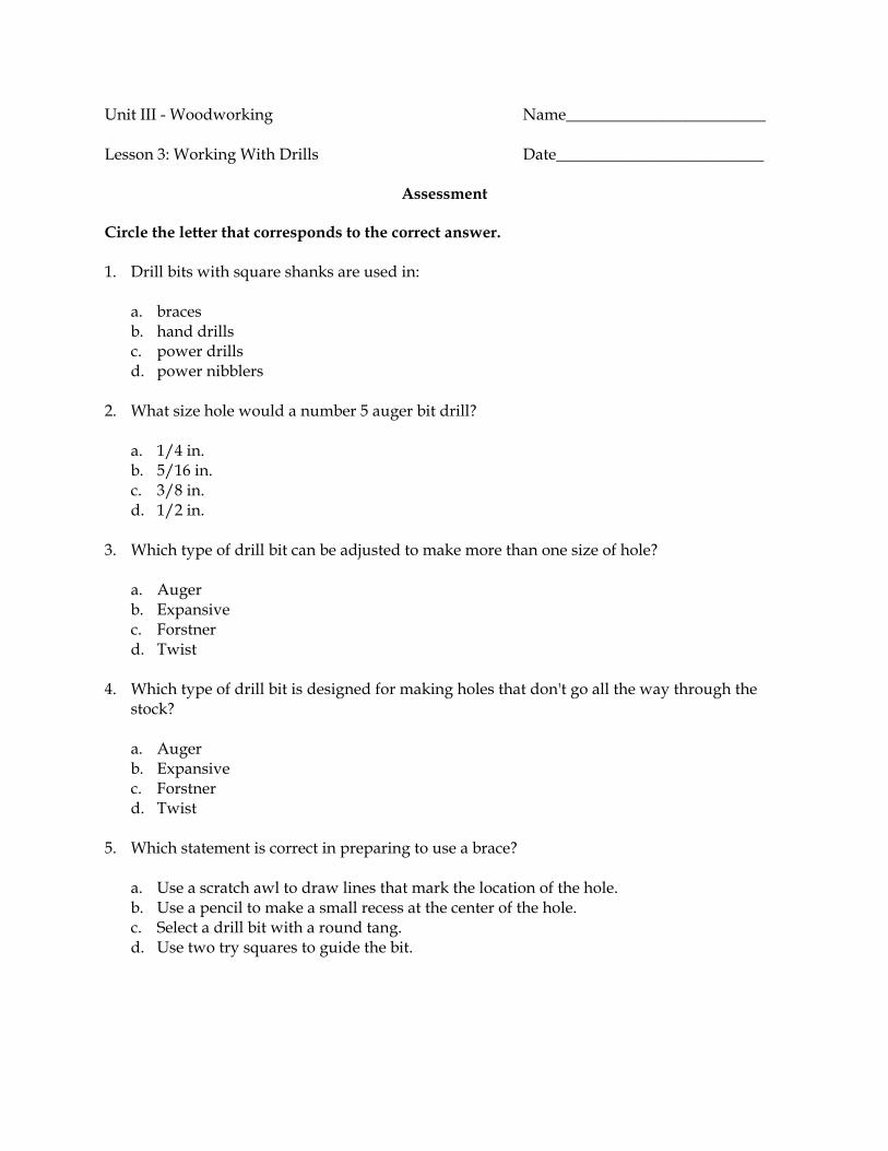
Unit III - Woodworking Name_________________________ Lesson 3: Working With Drills Date__________________________
Assessment Circle the letter that corresponds to the correct answer. 1. Drill bits with square shanks are used in:
a. braces b. hand drills c. power drills d. power nibblers
2. What size hole would a number 5 auger bit drill?
a. 1/4 in. b. 5/16 in. c. 3/8 in. d. 1/2 in.
3. Which type of drill bit can be adjusted to make more than one size of hole?
a. Auger b. Expansive c. Forstner d. Twist
4. Which type of drill bit is designed for making holes that don't go all the way through the
stock?
a. Auger b. Expansive c. Forstner d. Twist
5. Which statement is correct in preparing to use a brace?
a. Use a scratch awl to draw lines that mark the location of the hole. b. Use a pencil to make a small recess at the center of the hole. c. Select a drill bit with a round tang. d. Use two try squares to guide the bit.
6. Which statement is correct in preparing to use a power drill?
a. Select a drill bit with a square tang. b. Ensure the bit is installed at an angle. c. Secure keyed chucks by tightening around the chuck, using the key in each hole. d. Have the drill running at full speed before setting the bit on the stock.
7. Which statement is correct in using a power drill to drill a hole?
a. Drape the cord over the work to allow easy access. b. Use lighter pressure as the drill breaks through the stock. c. Use heavy pressure while drilling to make the hole quickly. d. Keep the bit horizontal to the work to ensure the hole is straight.
Complete the following short-answer questions. 8. When using a hand drill or power drill, what safety gear should be worn by the operator
and others in the work area? 9. Describe the two methods to avoid splitting the back of wood when drilling a hole.
a. b.
10. Describe the two methods to help in making holes straight.
a. b.
Ag Science I – Ag Mechanics I – Woodworking Using Fasteners • Page 1 of 10
Course Agricultural Science I
Unit Agricultural Mechanics I
Subunit Woodworking
Lesson Using Fasteners
Estimated Time 4 50-minute blocks Student Outcome
Demonstrate the use of common fasteners used in woodworking. Learning Objectives
1. Identify common types of nails and how are they used. 2. List considerations for using nails. 3. Describe common ways of fastening wood with nails. 4. Explain the correct procedure for fastening with nails. 5. Determine how the different types of screws are classified. 6. List considerations for using screws. 7. Explain the correct procedure for using screws to fasten wood. 8. Identify common adhesives. 9. List considerations for using adhesives.
Grade Level Expectations
Resources, Supplies & Equipment, and Supplemental Information
Resources 1. PowerPoint Slides
PPt 1 – Types of Nails PPt 2 – Methods of Fastening With Nails PPt 3 – How to Start a Nail Properly and Avoid Injury PPt 4 – Stagger Nails to Avoid Splitting Wood PPt 5 – Types of Screws PPt 6 – Using Clamps for Fastening With Adhesives
2. Agricultural Mechanics Unit for Agricultural Science I (Student Reference). University of Missouri-Columbia: Instructional Materials Laboratory, 2002.
3. Curriculum Enhancement for Agricultural Mechanics Unit for Agricultural Science I, “Unit III - Woodworking.” University of Missouri-Columbia: Instructional Materials Laboratory, 2004.
Supplies & Equipment See Unit III Activity for materials and equipment needed to complete the Unit Activity.
Supplemental Information 1. Internet Sites
How to Describe a Wood Screw. Sizes, Inc. Accessed September 14, 2007, from http://www.sizes.com/tools/wood_screws.htm.
Ag Science I – Ag Mechanics I – Woodworking Using Fasteners • Page 2 of 10
Wengert, Gene. A Brief History of Wood Glues. Woodweb. Accessed September 14, 2007, from http://www.woodweb.com/knowledge_base/A_brief_history_of_wood_glues.html.
2. Print Burkybile, C., D. Johnson, J. Lee, and C. Shelhamer. Agricultural Power and
Technology. Danville, IL: Interstate Publishers, 2005. Phipps, L. Mechanics in Agriculture. 4th ed. Danville, IL: Interstate Publishers, 1992. Phipps, L. and G. Miller. Introduction to Agricultural Mechanics. Upper Saddle River,
NJ: Prentice Hall Interstate, 2004. 3. Electronic Media
Wood Glue Video. Ask the Builder. Accessed September 14, 2007, from http://www.askthebuilder.com/Wood_Glue_Video.shtml.
Ag Science I – Ag Mechanics I – Woodworking Using Fasteners • Page 3 of 10
Instructor Directions Content Outline
Objective 1
As discussed in Unit I, most projects require assembling two or more parts. This is the job of fasteners and adhesives. There are many different kinds of fasteners and adhesives; nails are one of the most common. Nails are measured by the penny system (symbolized by the letter “d”), which measures their length, and by a gauge system, which measures their diameter. The gauge number goes down as the diameter increases. Some common types of nails and their uses are discussed at right. Refer to PPt 1.
PPt 1– Types of Nails
Identify common types of nails and how are they used. Common 1. Used in framing, rough nailing, board fencing 2. Used when appearance not important Box 1. Used in light construction 2. Similar to common nails but smaller diameter; less
likely to split wood Finishing 1. Used for interior finishing, such as cabinet, trim, and
furniture work 2. Rounded heads are usually countersunk, but can be
driven flush with the work Casing 1. Similar to finishing nails, but heavier 2. Used for window and door frames and similar work
Interest Approach
Ask the following, or similar, questions to guide discussion. 1. What are some common fasteners and adhesives used in the shop or around home? 2. What are some advantages screws have over nails? 3. What are the two most common types of screwdrivers? 4. What does the penny system measure? 5. What adhesive would students use to glue two pieces of wood together? What factors
make it a good adhesive for wood? Are there any disadvantages? (As an example, discuss white or yellow glue. A positive factor for either might be its relatively short clamping time. A disadvantage of white glue is that it is not resistant to solvents found in some finishes.)
Communicate the Learning Objectives
1. Identify common types of nails and how are they used. 2. List considerations for using nails. 3. Describe common ways of fastening wood with nails. 4. Explain the correct procedure for fastening with nails. 5. Determine how the different types of screws are classified. 6. List considerations for using screws. 7. Explain the correct procedure for using screws to fasten wood. 8. Identify common adhesives. 9. List considerations for using adhesives.
Ag Science I – Ag Mechanics I – Woodworking Using Fasteners • Page 4 of 10
Instructor Directions Content Outline
Roofing 1. Used with rolled roofing and composition shingles 2. Large flat head helps hold the material without
pulling through Duplex 1. Used for constructing forms for concrete 2. Used for nailing to posts for electric fencing Wire staple 1. Used in fence construction 2. Size is indicated by length and width
Objective 2 List considerations for using nails. 1. Easy to use 2. Fast to use 3. Not as strong as screws or glue
Objective 3
Basic methods of fastening wood with nails are discussed at right. Refer to PPt 2.
PPt 2 – Methods of
Fastening With Nails
Describe common ways of fastening wood with nails.
Straight nailing - nailing directly through top piece into the one underneath 1. End nailing - nailing through the thickness of one
piece and straight into the end of the other piece 2. Flat nailing - nailing two flat pieces together 3. Clinch nailing - flat nailing and bending the nail
down to the back of the second piece of stock. Increases strength.
Toe nailing - driving nails in at angle to increase strength
Objective 4
The procedure for fastening with nails is discussed at right. Refer to PPts 3 and 4.
PPt 3 – How to Start a Nail Properly and Avoid Injury
PPt 4 – Stagger Nails to
Avoid Splitting Wood
Explain the correct procedure for fastening with nails.
Choose the right nail for the job. 1. Use the right type of nail for the material. 2. Use the right size. For best results, use a nail three
times as long as the thickness of the top piece. Choose the right hammer. 1. A light hammer (7 oz) is better for driving brads and
finishing nails. 2. A heavy hammer (16 oz to 20 oz) is better for driving
large nails and spikes.
Ag Science I – Ag Mechanics I – Woodworking Using Fasteners • Page 5 of 10
Instructor Directions Content Outline
Observe basic safety procedures. 1. Everyone using tools or in the work area should wear
appropriate protective eyewear. 2. Make sure the head of the hammer is firmly attached
and that the handle is not broken. 3. Do not use the hammer on materials that can damage
the head, such as concrete. If needed, drill a pilot hole slightly smaller than the diameter of the nail to avoid splitting the stock. Follow safety and usage procedures for the type of drill being used. Hold the nail with the thumb and index finger and set the point of the nail on the stock. Keep fingers high on the nail. This improves the chance that they will be pushed clear rather than smashed by a missed stroke. Hold the hammer near the end of the handle, keeping eyes focused on the nail head. Start the nail with light taps. When the nail stands by itself, remove the steadying hand. Use the wrist and arm to drive the nail with even strokes. The face of the hammer should hit flat against the nail. Drive the nail until it is flush. Set the nail with a nail set if necessary. If more than one nail is needed in the same place, stagger the nails to reduce the chance of splitting the wood. Materials and equipment should be returned to their assigned place when finished.
Objective 5 Screws are another common fastener. Screws are also measured by length and diameter, but unlike nails, gauge increases with the diameter instead of decreases.
Determine how the different types of screws are classified. By material they hold 1. Wood screws
a. Threads are specifically designed to hold wood. b. The shank is threaded at the bottom and
unthreaded at the top to pull the top piece of
Ag Science I – Ag Mechanics I – Woodworking Using Fasteners • Page 6 of 10
Instructor Directions Content Outline
Screws of a given length are available in different diameters. Refer to PPt 5.
PPt 5 – Types of Screws
stock against the bottom. 2. Sheet metal screws
a. Wide threads run the length of the shank and allow the metal to sit between the threads.
b. Sheet metal screws can also fasten metal to wood or be used on fiberboard.
3. Lag screws a. Threads are coarse. b. Lag screws are used in structural timber and for
anchoring. By material they are made from 1. Steel 2. Brass By finish 1. Blued 2. Galvanized 3. Chromium 4. Nickel By shape of head 1. Flat 2. Round 3. Oval 4. Pan By the tool used to turn them 1. Standard slotted head 2. Phillips head
Objective 6 List considerations for using screws. 1. More holding power than nails 2. Can be removed without damaging wood 3. Allow for easy assembly and disassembly of the parts
Objective 7 Explain the correct procedure for using screws to fasten wood. Measure the materials to be joined for thickness. For best results use a screw three times as long as the thickness of the top board. If this is too long, choose a shorter screw. Mark the stock using a pencil.
Ag Science I – Ag Mechanics I – Woodworking Using Fasteners • Page 7 of 10
Instructor Directions Content Outline
Determine the size of the shank and pilot holes needed. Consult a chart or compare the screw to different bits until the correct ones are found. 1. The bit for the shank hole should be the same
diameter as the shank of the screw. 2. The pilot hole should be the same size as the center
(core) of the screw, not the diameter of the threads. Observe basic safety procedures. 1. Everyone using tools or in the work area should wear
appropriate protective eyewear. 2. Follow safety and usage steps for the type of drill
being used. Secure the two pieces together and drill the pilot hole through both pieces of wood to a depth equal to the length of the screw. If the bit is too long, mark the correct depth with a piece of tape or use a gauge to drill the hole. Use the shank drill to drill through the first piece of wood only. If necessary, use a countersink to enlarge the top of the hole until the screw sits flush with the work. If a combination bit corresponding to the screw is available, several of the steps above can be combined. Assemble pieces using a screwdriver that properly fits the screw. Do not over tighten. Materials and equipment should be returned to their assigned place when finished.
Objective 8
Adhesives work by bonding surfaces together. Only a few of the many adhesives available are discussed at right. In the same way that the same kind of power tool will involve different setup and use procedures when made by
Identify common adhesives. Polyvinyl adhesives (PVA) - “white glue” 1. Convenient, ready to use 2. Short clamp time (time needed to set) 3. Cures (reaches full strength) in 24 hours 4. Good for interior woodwork 5. Lacks heat and moisture resistance
Ag Science I – Ag Mechanics I – Woodworking Using Fasteners • Page 8 of 10
Instructor Directions Content Outline
different companies, similar-looking adhesives can have different chemical compositions and therefore different safety recommendations. Refer to PPT 6.
PPt 6 – Using Clamps for Fastening With Adhesives
Aliphatic resin glue “yellow glue” 1. Similar to PVA but stronger 2. More resistant than PVA to varnish, lacquer, and
paint 3. Sands easily 4. Good for interior woodwork 5. Lacks moisture resistance Solvent-base contact cement 1. Quick-drying 2. Used for bonding laminates to wood 3. Toxic and flammable. Consult manufacturer’s
specifications. Water-base contact cement 1. Nontoxic, nonflammable alternative to solvent-base
cements 2. Can be used with plastics and lacquered surfaces 3. Should not be used with metal or wood veneer Epoxy cement 1. Two-part adhesive 2. Extremely strong and waterproof 3. Can be sanded 4. Setting speed can be controlled 5. Expensive for large applications 6. Can produce heat in the curing process that can warp
materials or burn skin. Consult manufacturer’s specifications for other safety considerations.
Objective 9 List considerations for using adhesives. Assembly time - How long after applying the glue do you have to put the pieces together? Clamp or set time - How long do the pieces need to remain clamped after the glue has been applied? Curing time - How long does the piece need before the joint reaches full strength? What types of material will the adhesive bond? What environments can the adhesive withstand?
Ag Science I – Ag Mechanics I – Woodworking Using Fasteners • Page 9 of 10
Instructor Directions Content Outline
1. Is it water or heat resistant? 2. Will it resist solvents in finishes? What are the safety considerations? 1. Is it toxic? 2. Is it flammable? 3. Is there adequate ventilation? 4. Consult manufacturer’s specifications for other
considerations. Application:
Other activities 1. Accompany or follow the lesson with instructor
demonstrations of each type of fastener or adhesive students will be using and procedures they will be expected to perform. Discuss any specific safety features that were not covered in the lesson outline above, and supplement the lesson with discussion of any tools or materials not covered. Begin or end demonstrations by having students review safety and use procedures. Have students fasten boards together using the fasteners and adhesives they will be using in the shop.
2. Give each student eight boards to fasten in various ways. Have them fasten two by using nails, two by using screws, two by using adhesive, and the last two by using nails and adhesives. Allow the adhesive to set overnight. Instruct students to unfasten the boards the next day. Ask students which fasteners were easiest and hardest to remove or take apart. Ask which fasteners damaged the wood the most.
3. Make an identification board of different fasteners. Find various fasteners around the shop or purchase them at a local hardware store. Glue them to a board and display the board for students.
Closure/Summary Nails are easy and fast to use but are not as strong as screws or glue. Clinch nailing and toe nailing increase the strength of the connection. Screws are categorized according to the material they hold, the material they are made of, the shape of the head, and the type of screwdriver used to turn them. For best results, nails and screws should be three times as long as the thickness of the top piece. Many different types of adhesives are available. Considerations for selecting an adhesive
Ag Science I – Ag Mechanics I – Woodworking Using Fasteners • Page 10 of 10
Instructor Directions Content Outline
include how long it takes to harden, what types of material it can bond, and what environments the adhesive can withstand.
Evaluation: Quiz Answers: 1. b 2. c 3. b 4. a 5. d 6. a 7. a 8. b 9. d 10. b 11. c 12. f 13. b 14. a 15. e 16. d 17. a. Staggering the nails when flat nailing
b. Drilling a pilot hole a little smaller than the diameter of the nail
18. The nail should be held with the thumb and index finger high on the nail. This improves the chances that fingers will be pushed clear rather than smashed by a missed stroke.
19. Student should list three of the following: a. Material they hold b. Material they are made from c. Finish d. Shape of their head e. Tool used to install them
20. Student should list three of the following: a. Safety b. Assembly time c. Clamp or set time d. Curing time e. Materials it will bond f. Ability to withstand elements such as water,
heat, or solvents
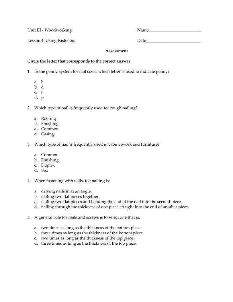
Unit III - Woodworking Name_________________________ Lesson 4: Using Fasteners Date__________________________
Assessment Circle the letter that corresponds to the correct answer. 1. In the penny system for nail sizes, which letter is used to indicate penny?
a. b b. d c. f d. p
2. Which type of nail is frequently used for rough nailing?
a. Roofing b. Finishing c. Common d. Casing
3. Which type of nail is frequently used in cabinetwork and furniture?
a. Common b. Finishing c. Duplex d. Box
4. When fastening with nails, toe nailing is:
a. driving nails in at an angle. b. nailing two flat pieces together. c. nailing two flat pieces and bending the end of the nail into the second piece. d. nailing through the thickness of one piece straight into the end of another piece.
5. A general rule for nails and screws is to select one that is:
a. two times as long as the thickness of the bottom piece. b. three times as long as the thickness of the bottom piece. c. two times as long as the thickness of the top piece. d. three times as long as the thickness of the top piece.

6. A wood screw is designed with threads:
a. at the bottom and no threads near the head. b. near the head and no threads at the bottom. c. throughout the length. d. that are extremely coarse.
7. How does the head of a flat head screw fit on the surface of wood?
a. Flush b. On top c. 1/16 in. above d. Partially below and above
8. When preparing to install a screw, which hole is drilled first?
a. Countersink b. Pilot c. Shank d. Starter
9. Set time for an adhesive is how long?
a. The worker has to assemble the pieces. b. The glue will continue to hold the pieces. c. It takes for the bond to reach full strength. d. The pieces need to remain clamped after gluing.
10. Aliphatic resin glue is:
a. not as strong as PVA. b. more resistant to finishes than PVA. c. rarely used in woodworking because it is difficult to sand. d. more moisture-resistant than epoxy.
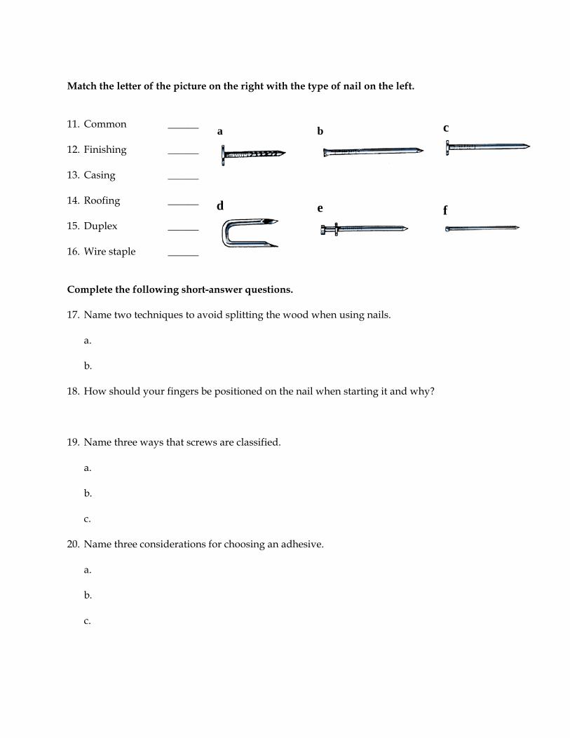
Match the letter of the picture on the right with the type of nail on the left. 11. Common ______ 12. Finishing ______ 13. Casing ______ 14. Roofing ______ 15. Duplex ______ 16. Wire staple ______ Complete the following short-answer questions. 17. Name two techniques to avoid splitting the wood when using nails.
a. b.
18. How should your fingers be positioned on the nail when starting it and why? 19. Name three ways that screws are classified.
a. b. c.
20. Name three considerations for choosing an adhesive.
a. b. c.
a b
c
d e
f
Unit III - Woodworking Unit III Activity
Woodworking Plans
Objective: Student will use the skills learned in this unit to construct woodworking projects. The following woodworking plans are included in this activity.
Boot jack Flower box Step stool Tool box
These plans represent projects that vary in terms of their complexity and in the amount of time and materials needed to complete them. The instructor should choose project plans for this unit based on the skill level of the students and the time available to work on the project. If students are selecting their own projects, the instructor should screen all student plans to determine that they are appropriate as part of a vocational agricultural curriculum. Career and Technical Education Resources (CATER) at the University of Missouri-Columbia has the following additional plans available: Agricultural Mechanics Plans (a set of single sheet plans for wood, metal, and wood and metal projects; catalog number 10-7804-I) and Agricultural Mechanics Plans (Set) (a set of 28 bulletin plans with pictures and sequenced building procedures and 50 single sheet plans in woodworking, metals, and welding; catalog number 10-7810-S). Materials can be ordered on their web site at www.cater.missouri.edu or by calling (800) 392-7217. The Missouri Department of Conservation is another source for woodworking plans. Access their web site at http://www.mdc.mo.gov/nathis/woodwork.

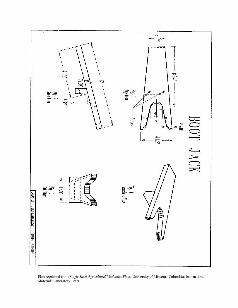
Plan reprinted from Single Sheet Agricultural Mechanics Plans. University of Missouri-Columbia: Instructional Materials Laboratory, 1994.
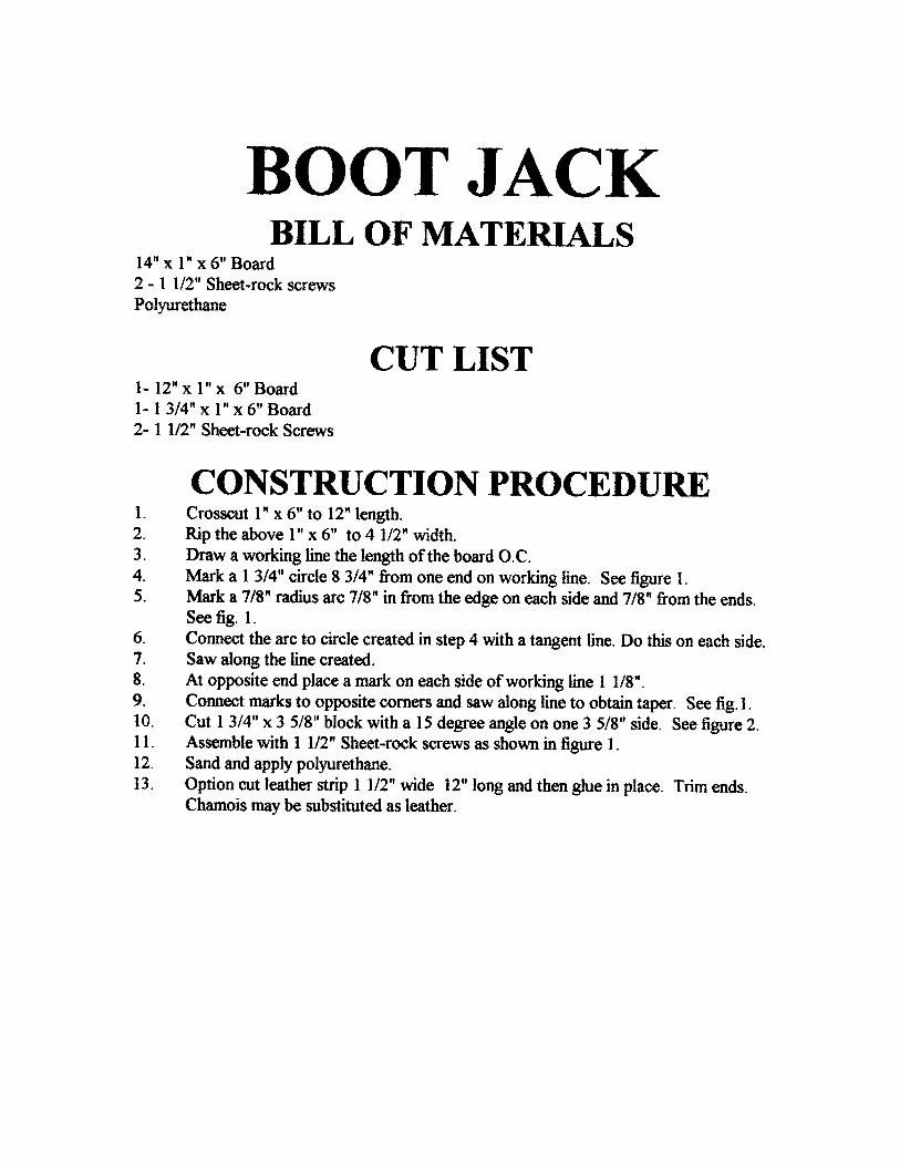
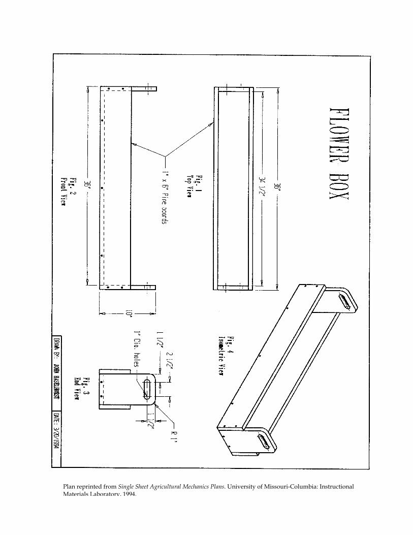
Plan reprinted from Single Sheet Agricultural Mechanics Plans. University of Missouri-Columbia: Instructional Materials Laboratory, 1994.
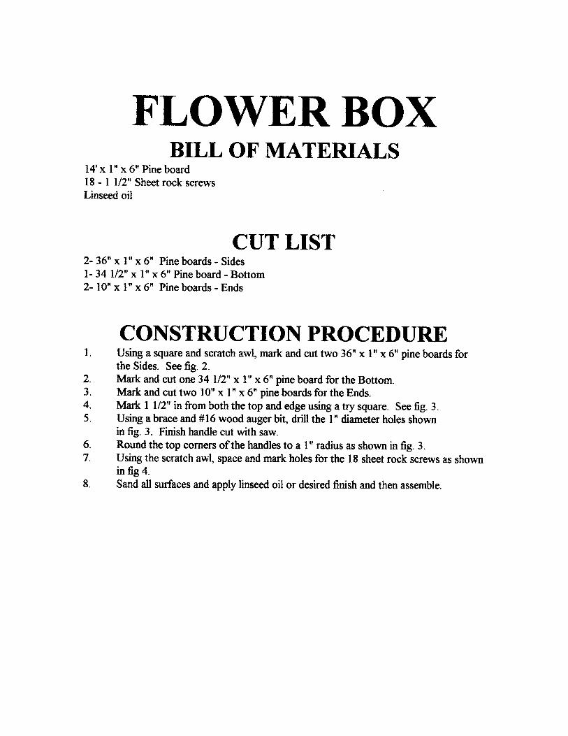

Plan reprinted from Single Sheet Agricultural Mechanics Plans. University of Missouri-Columbia: Instructional Materials Laboratory, 1994.
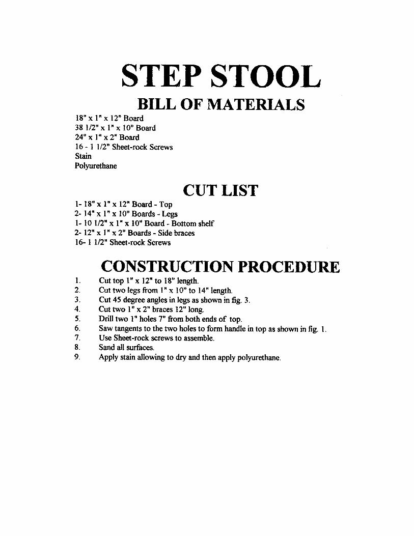
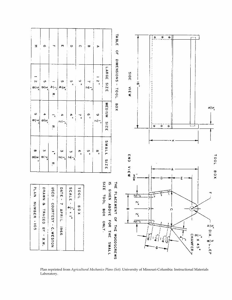
Plan reprinted from Agricultural Mechanics Plans (Set). University of Missouri-Columbia: Instructional Materials Laboratory.

Tool Box Construction Procedure
1. Select the size tool box desired from the table on front page, length can be any length. Length shown is for small size tool box.
2. For the handle use a 3/4" dowel rod or thin wall conduit. 3. Use 1/8" or 1/4" plywood or tempered masonite for the sides. 4. Use 3/8" plywood for the bottom. 5. Carefully lay out end pieces and cut to dimensions. The end pieces may be clamped
together to be finished at the same time. 6. Counterbore end pieces to receive handle and secure bottom. Use good spacing for screws. 7. Lay out, cut, and square up sides to dimensions. Bevel the bottom edges to the proper
angle. Cut 1/8" chamfers on outside of top edges of the side pieces. 8. Lay out, drill, and countersink the holes for screws to hold the sides in place. 9. Finish by oiling with linseed oil or by painting if desired.
♦ Page 1 ♦
Agricultural Science I Curriculum Guide: Agricultural Mechanics Unit for Agricultural Science I Unit: III. Woodworking Unit Objective:
Students will apply basic woodworking skills by constructing an appropriate woodworking project.
Show-Me Standards: 2.5, CA3 References:
Agricultural Mechanics Building Plans. University of Missouri-Columbia, Instructional Materials Laboratory, 1994. Agricultural Mechanics Plans (Set). University of Missouri-Columbia, Instructional Materials Laboratory. Agricultural Mechanics Unit for Agricultural Science I. University of Missouri-Columbia, Instructional Materials Laboratory, 2002. Woodworking for Wildlife. Missouri Department of Conservation. Accessed November 13, 2003, from http://www.conservation.state.mo.us/nathis/woodwork/.
Instructional Strategies/Activities: • Students will engage in study questions in lessons 1 through 4. • Students will complete AS 1.1, Measurement Review; AS 1.2, Calculating
Area and Board Feet; AS 2.1, Using a Crosscut Saw; AS 2.2, Using a Rip Saw; AS 2.3, Making a 45-Degree Miter Cut; AS 2.4, Making a Straight Cut With a Portable Circular Saw; AS 2.5, Making a Miter Cut With a Table Saw; AS 3.1, Using a Brace; and AS 3.2, Using a Portable Drill.
• Additional activities that relate to the unit objective can be found under the heading “Other Activities” in the following locations: p. III-5 and pp. III-102–III-103 (1, 2, 3).

Agricultural Science I
♦ Page 2 ♦
Performance-Based Assessment: Students will use common woodworking tools and procedures discussed in class to lay out and construct an appropriate woodworking project. Assessment will be based on the overall quality of the work and the ability to safely and correctly complete the project within the available time.
Agricultural Science I
♦ Page 3 ♦
Agricultural Mechanics Unit for Agricultural Science I Unit III—Woodworking Instructor Guide The instructor should assign the performance-based assessment activity at the beginning of the unit. Students will work toward completing the activity as they progress through the unit lessons. The assessment activity will be due at the completion of the unit. 1. Use or adapt the activity sheets found in the unit to assess student
competency at performing basic woodworking procedures. Review or supplement these activities as needed, based on student mastery of the procedures and the tools the students will be using. NOTE: Students should only complete this performance-based activity if they have mastered all the relevant competencies and have the instructor’s permission to perform the activity.
2. For the performance-based assessment activity, have students apply the skills and procedures discussed in the unit to construct an appropriate woodworking project. a. See the Unit III Activity, Woodworking Plans, pp. III-121–III-130, for a
selection of project plans and additional details. Single-sheet plans are included for a boot jack, flower box, step stool, and tool box.
b. For additional project plans, see Agricultural Mechanics Building Plans and Agricultural Mechanics Plans (Set), available from the Instructional Materials Laboratory, University of Missouri-Columbia, accessed November 13, 2003, at http://www.iml.coe.missouri.edu/.
c. Plans are also available from the Missouri Department of Conservation. See Woodworking for Wildlife, accessed November 14, 2003, at http://www.conservation.state.mo.us/nathis/woodwork/.
3. The student handout for this activity is a Project Completion Checklist and
Project Evaluation Checklist. Students can use the checklists to track the progress of their project and evaluate their work. Supplement or modify the student handout to reflect actual projects as needed.
4. Have students turn in their completed projects. 5. The final assessment score will be based on the overall quality of the work
and the ability to safely and correctly complete the project within the available time.
Agricultural Science I
♦ Page 4 ♦
6. ADDITIONAL ACTIVITY: If all students are building the same project, a display board can be made as a teaching aid for the project. To make a display board, mount correctly made examples of each project piece on a board. Label each piece and indicate the number of pieces needed. Have students compare their project pieces with the correctly made examples. Students should make sure their pieces match the examples before proceeding.
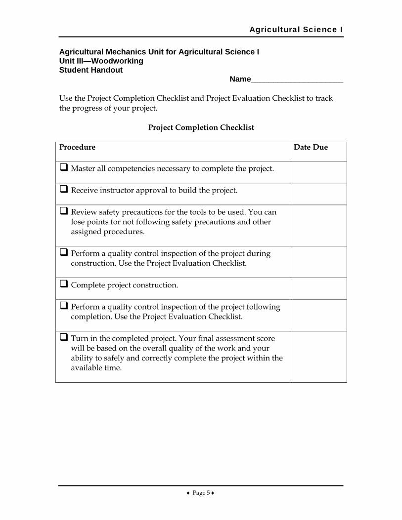
Agricultural Science I
♦ Page 5 ♦
Agricultural Mechanics Unit for Agricultural Science I Unit III—Woodworking Student Handout
Name_____________________ Use the Project Completion Checklist and Project Evaluation Checklist to track the progress of your project.
Project Completion Checklist Procedure
Date Due
Master all competencies necessary to complete the project.
Receive instructor approval to build the project.
Review safety precautions for the tools to be used. You can lose points for not following safety precautions and other assigned procedures.
Perform a quality control inspection of the project during construction. Use the Project Evaluation Checklist.
Complete project construction.
Perform a quality control inspection of the project following completion. Use the Project Evaluation Checklist.
Turn in the completed project. Your final assessment score will be based on the overall quality of the work and your ability to safely and correctly complete the project within the available time.
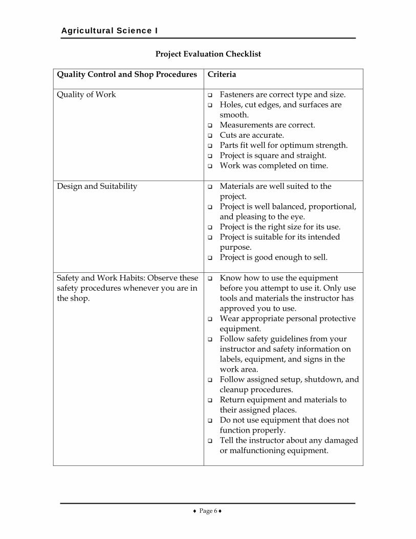
Agricultural Science I
♦ Page 6 ♦
Project Evaluation Checklist
Quality Control and Shop Procedures
Criteria
Quality of Work Fasteners are correct type and size. Holes, cut edges, and surfaces are
smooth. Measurements are correct. Cuts are accurate. Parts fit well for optimum strength. Project is square and straight. Work was completed on time.
Design and Suitability Materials are well suited to the
project. Project is well balanced, proportional,
and pleasing to the eye. Project is the right size for its use. Project is suitable for its intended
purpose. Project is good enough to sell.
Safety and Work Habits: Observe these safety procedures whenever you are in the shop.
Know how to use the equipment before you attempt to use it. Only use tools and materials the instructor has approved you to use.
Wear appropriate personal protective equipment.
Follow safety guidelines from your instructor and safety information on labels, equipment, and signs in the work area.
Follow assigned setup, shutdown, and cleanup procedures.
Return equipment and materials to their assigned places.
Do not use equipment that does not function properly.
Tell the instructor about any damaged or malfunctioning equipment.
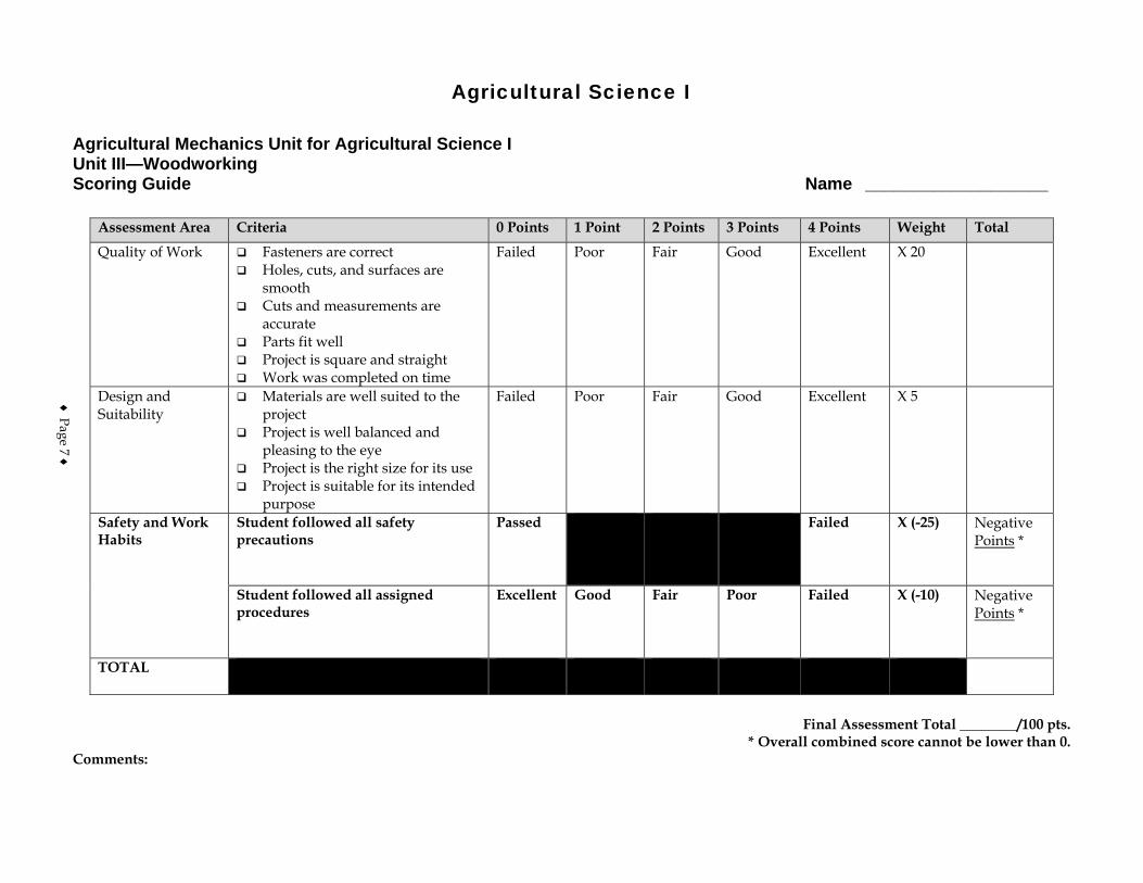
Agricultural Science I
Agricultural Mechanics Unit for Agricultural Science I Unit III—Woodworking Scoring Guide Name ___________________
Assessment Area Criteria 0 Points 1 Point 2 Points 3 Points 4 Points Weight Total
Quality of Work Fasteners are correct Holes, cuts, and surfaces are
smooth Cuts and measurements are
accurate Parts fit well Project is square and straight Work was completed on time
Failed Poor Fair Good Excellent X 20
Design and Suitability
Materials are well suited to the project
Project is well balanced and pleasing to the eye
Project is the right size for its use Project is suitable for its intended
purpose
Failed Poor Fair Good Excellent X 5
Safety and Work Habits
Student followed all safety precautions
Passed Failed X (-25) Negative Points *
Student followed all assigned procedures
Excellent Good Fair Poor Failed X (-10) Negative Points *
TOTAL
Final Assessment Total ________/100 pts.
* Overall combined score cannot be lower than 0. Comments:
♦ Page 7 ♦

♦ Page 8 ♦
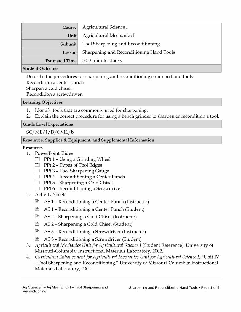
Ag Science I – Ag Mechanics I – Tool Sharpening and Reconditioning
Sharpening and Reconditioning Hand Tools • Page 1 of 5
Course Agricultural Science I
Unit Agricultural Mechanics I
Subunit Tool Sharpening and Reconditioning
Lesson Sharpening and Reconditioning Hand Tools
Estimated Time 3 50-minute blocks Student Outcome
Describe the procedures for sharpening and reconditioning common hand tools. Recondition a center punch. Sharpen a cold chisel. Recondition a screwdriver.
Learning Objectives
1. Identify tools that are commonly used for sharpening. 2. Explain the correct procedure for using a bench grinder to sharpen or recondition a tool.
Grade Level Expectations
SC/ME/1/D/09-11/b Resources, Supplies & Equipment, and Supplemental Information
Resources 1. PowerPoint Slides
PPt 1 – Using a Grinding Wheel PPt 2 – Types of Tool Edges PPt 3 – Tool Sharpening Gauge PPt 4 – Reconditioning a Center Punch PPt 5 – Sharpening a Cold Chisel PPt 6 – Reconditioning a Screwdriver
2. Activity Sheets AS 1 – Reconditioning a Center Punch (Instructor) AS 1 – Reconditioning a Center Punch (Student) AS 2 – Sharpening a Cold Chisel (Instructor) AS 2 – Sharpening a Cold Chisel (Student) AS 3 – Reconditioning a Screwdriver (Instructor) AS 3 – Reconditioning a Screwdriver (Student)
3. Agricultural Mechanics Unit for Agricultural Science I (Student Reference). University of Missouri-Columbia: Instructional Materials Laboratory, 2002.
4. Curriculum Enhancement for Agricultural Mechanics Unit for Agricultural Science I, “Unit IV - Tool Sharpening and Reconditioning.” University of Missouri-Columbia: Instructional Materials Laboratory, 2004.
Ag Science I – Ag Mechanics I – Tool Sharpening and Reconditioning
Sharpening and Reconditioning Hand Tools • Page 2 of 5
Supplies & Equipment See AS 1 through AS 3 for materials and equipment needed to complete the Activity
Sheets. Supplemental Information
1. Internet Sites “Grinders – Bench, Floor, and Hand.” Environmental Health and Safety. University
of Nebraska–Lincoln. Accessed September 19, 2007, from http://ehs.unl.edu/sop/s-grinders.pdf.
2. Print Cooper, E. Agricultural Mechanics: Fundamentals and Applications. 3rd ed. Albany,
NY: Del Mar Publishers, 1997. Phipps, L. Mechanics in Agriculture. 4th ed. Danville, IL: Interstate Publishers, 1992. Phipps, L. and G. Miller. Introduction to Agricultural Mechanics. Upper Saddle River,
NJ: Prentice Hall Interstate, 2004. Walker, J. Modern Metalworking. Tinley Park, IL: The Goodheart-Willcox Company,
Inc., 2000. 3. Electronic Media
Quick and Easy Tool Sharpening. Woodvision Woodworking Video Clips. Wood Magazine. Accessed September 19, 2007, from http://www.youtube.com/watch?v=3yvJavgK6mo.
Ag Science I – Ag Mechanics I – Tool Sharpening and Reconditioning
Sharpening and Reconditioning Hand Tools • Page 3 of 5
Instructor Directions Content Outline
Objective 1
Procedures for sharpening and reconditioning tools are discussed at right. When students have reviewed these procedures, the instructor version of AS 1-3 should be used to demonstrate the correct way to sharpen and recondition the tools described. The student version of these activities should be assigned to evaluate student competency of these activities.
AS 1 – Reconditioning a
Center Punch
AS 2 – Sharpening a Cold Chisel
AS 3 – Reconditioning a
Screwdriver
Identify tools that are commonly used for sharpening. Files 1. Available in different styles and coarseness, including
files for specific jobs 2. Coarse files are used for larger jobs, such as mower
blades 3. Most sharpening work is done with fine-toothed files Stones 1. Can be natural or manmade 2. Available in different configurations
a. Bench stones - used setting on a bench b. Hand stones - held in the hand during use c. Wheels - driven by a grinder
3. Often used with water or oil to clean the stone and facilitate sharpening
Objective 2
General use and safety information for the bench grinder
Explain the correct procedure for using a bench grinder to sharpen or recondition a tool.
Choose a wheel with the right grit for the job. 1. As grit number increases, abrasives become finer.
Interest Approach
Have students discuss reasons for sharpening and reconditioning tools. Is a sharp tool safer than a dull one? Why? Is it more cost-effective to buy a new tool or recondition one you have? Why? What other reasons might there be for reconditioning tools? Factors might include the quality of the work produced by a well-maintained tool. Reconditioning can prolong the life of tools the student already has or, by recoditioning tools others don’t want, reconditioning can be a way to expand the number of tools he or she has.
Communicate the Learning Objectives
1. Identify tools that are commonly used for sharpening. 2. Explain the correct procedure for using a bench grinder to sharpen or recondition a tool.
Ag Science I – Ag Mechanics I – Tool Sharpening and Reconditioning
Sharpening and Reconditioning Hand Tools • Page 4 of 5
Instructor Directions Content Outline
were discussed in Unit II Lesson 2. Review or supplement this material as needed, based on student mastery and tools the students will be using. Additional considerations for using the bench grinder are listed below. Refer to PPts 1-6
PPt 1 – Using a Grinding Wheel
PPt 2 – Types of Tool
Edges
PPt 3 – Tool Sharpening Gauge
PPt 4 – Reconditioning a
Center Punch
PPt 5 – Sharpening a Cold Chisel
PPt 6 – Reconditioning a
Screwdriver
2. Medium-grit wheels are acceptable for most tool-sharpening jobs.
Follow safety procedures. 1. A face shield and a leather apron are recommended
when using the grinder. 2. Do not use a wheel that is damaged or out of round. 3. Dress or replace the wheel as needed. Adjust the tool rest. It should be 1/16 in. from the wheel. Set at an angle as needed. Move the work slowly across the face of the wheel to avoid overheating the metal. Tools have different kinds of edges. Always grind the tool back to its original edge. Do not grind with the sides of the wheel. Use cutting oil or water as needed to clean the stone or cool the blade. Overheating the tool and allowing it to cool slowly will draw its temper, or soften the tool. Check the edge of the tool. A tool gauge can be used to accurately check a number of tools.
Application:
AS 1 – Reconditioning a Center Punch
AS 2 – Sharpening a Cold
Chisel
AS 3 – Reconditioning a Screwdriver
AS 1 – AS 3 Results will vary. Other activities 1. Have students inspect tools around the shop and
identify ones that are dull or misshapen. Ask them which method they think would be best to sharpen or recondition each tool.
Closure/Summary Files, hand stones and bench stones, and a bench grinder
are commonly used to sharpen tools. Files are available in different degrees of coarseness, with fine-toothed files being the type most often used to sharpen tools. With a
Ag Science I – Ag Mechanics I – Tool Sharpening and Reconditioning
Sharpening and Reconditioning Hand Tools • Page 5 of 5
Instructor Directions Content Outline
bench grinder, medium-grit wheels are acceptable for most tool sharpening jobs. Tools should always be ground back to their original edge.
Evaluation: Quiz Answers: 1. d 2. a 3. b 4. Face 5. a. Face shield
b. Leather apron 6. To use a tool to make the diameter perfectly round
and the face square, to clean debris from the abrasive material
7. This helps prevent the tool from overheating. 8. To soften the tool through overheating and slow
cooling
Unit IV - Tool Sharpening and Reconditioning AS 1 (Instructor) Lesson 1: Sharpening and Reconditioning Hand Tools
Reconditioning a Center Punch Objective: Students will observe how to recondition a center punch. Directions: Use a grinding wheel to recondition a center punch. Materials and Equipment: Bench grinder Medium-grit grinding wheel Center punch needing reconditioning Tool gauge Container of water for cooling the punch Face shield or other approved eye and face protection* Leather apron or any other protective clothing recommended by the instructor * Everyone participating in or observing the demonstration should wear appropriate protective eyewear. Procedure: 1. Refer to TM 1.4 Reconditioning a Center Punch. Explain that the center punch tapers twice,
once from the wide diameter of the punch, which is designed to withstand the blows of a hammer, and then again, to form the point. The angle of this point is usually between 60 and 75 degrees. Inform students of preferred angle. To recondition the point you must grind this second angle back into the punch, making it symmetrical, or the same all the way around.
2. Wear appropriate safety equipment. 3. Inspect the wheel. 4. Adjust the tool rest. It should be 1/16 in. from the wheel. 5. Stand to the side, start the grinder, and let the wheel run before using. Wheels that are going
to break generally do so within the first minute of use. 6. Set the punch on the tool rest, pointed upward, at the desired angle to the wheel. Turn the
punch clockwise while grinding to make an even point. 7. Dip the punch in water frequently to avoid overheating it. 8. Check the angel of the punch using the tool gauge. 9. Grind until the desired angle is reached. 10. Observe safety and cleanup procedures. 11. Assign AS 1 to be performed by students.
Unit IV - Tool Sharpening and Reconditioning AS 1 (Student) Lesson 1: Sharpening and Reconditioning Hand Tools
Reconditioning a Center Punch Objective: Students will recondition a center punch. Directions: Students will use a grinding wheel to recondition a center punch. Materials and Equipment: Bench grinder Medium-grit grinding wheel Center punch needing reconditioning Tool gauge Container of water for cooling the punch Face shield or other approved eye and face protection* Leather apron or any other protective clothing recommended by the instructor * Everyone participating in or observing the demonstration should wear appropriate protective eyewear. Procedure: 1. Wear appropriate safety equipment. 2. Inspect the wheel. Is it the right grit? Is it dressed and free of damage? 3. Adjust the tool rest. It should be 1/16 in. from the wheel. 4. Stand to the side, start the grinder, and let the wheel run before using. Wheels that are going
to break generally do so within the first minute of use. 5. Set the punch on the tool rest, pointed upward, at the desired angle to the wheel. Turn the
punch clockwise while grinding to make an even point. 6. Dip the punch in water frequently to avoid overheating it. 7. Check the angle of the punch using the tool gauge. 8. Grind until the desired angle is reached. 9. Observe safety and cleanup procedures. Materials and equipment should be returned to
their assigned places. 10. Turn in work to be graded by instructor.
Unit IV - Tool Sharpening and Reconditioning AS 2 (Instructor) Lesson 1: Sharpening and Reconditioning Hand Tools
Sharpening a Cold Chisel Objective: Student will observe how to sharpen a cold chisel. Directions: Use a grinding wheel to sharpen a cold chisel. Materials and Equipment: Bench grinder Medium-grit grinding wheel Cold chisel needing reconditioning Tool gauge Square
Container of water for cooling the chisel Face shield or other approved eye and face protection* Leather apron or any other protective clothing recommended by the instructor
* Everyone participating in or observing the demonstration should wear appropriate protective eyewear. Procedure: 1. Refer to TM 1.5 Sharpening a Cold Chisel. Explain that, like the center punch, the cold chisel
tapers twice, once from the wide diameter of the chisel, which is designed to withstand the blows of a hammer, and then again, to form the point. The angle of this point is usually between 60 and 75 degrees. Inform students of preferred angle. To recondition the point you must grind this second angle back into the punch, making it even, all the way across the chisel. If desired, explain that the work done with the chisel determines how it should be ground. For working on flat plate, chisels are often ground with a slightly curved cutting edge to avoid gouging the stock. If it will be used for cutting work in a vise, the edge should be ground straight across. Directions below are for grinding a straight edge into the chisel.
2. Wear appropriate safety equipment. 3. Inspect the wheel. 4. Adjust the tool rest. It should be 1/16 in. from the wheel. 5. Stand to the side, start the grinder, and let the wheel run before using. Wheels that are going
to break generally do so within the first minute of use. 6. Set the chisel on the tool rest, pointed upward, leaning in at the desired angle to the wheel.
Make one pass across the wheel with the edge of the chisel. 7. Turn the chisel over and repeat the action on the other side. 8. Dip the chisel in water frequently to avoid overheating it. 9. Continue alternating passes across the wheel until the edge is sharpened. 10. Check to see if the edge is square. 11. Check the angle of the chisel using the tool gauge. 12. Grind until the desired angle is reached. 13. Observe safety and cleanup procedures. 14. Assign AS 2 to be performed by students.
Unit IV - Tool Sharpening and Reconditioning AS 2 (Student) Lesson 1: Sharpening and Reconditioning Hand Tools
Sharpening a Cold Chisel Objective: Students will sharpen a cold chisel. Directions: Students will use a grinding wheel to sharpen a cold chisel. Materials and Equipment: Bench grinder Medium-grit grinding wheel Cold chisel needing reconditioning Tool gauge Square
Container of water for cooling the chisel Face shield or other approved eye and face protection* Leather apron or any other protective clothing recommended by the instructor
* Everyone participating in or observing the demonstration should wear appropriate protective eyewear. Procedure: 1. Wear appropriate safety equipment. 2. Inspect the wheel. 3. Adjust the tool rest. It should be 1/16 in. from the wheel. 4. Stand to the side, start the grinder, and let the wheel run before using. Wheels that are going
to break generally do so within the first minute of use. 5. Set the chisel on the tool rest, pointed upward, leaning in at the desired angle to the wheel.
Make one pass across the wheel with the edge of the chisel. 6. Turn the chisel over and repeat the action on the other side. 7. Dip the chisel in water frequently to avoid overheating it. 8. Continue alternating passes across the wheel until the edge is sharpened. 9. Check to see if the edge is square. 10. Check the angle of the chisel using the tool gauge. 11. Grind until the desired angle is reached. 12. Observe safety and cleanup procedures. Materials and equipment should be returned to
their assigned places. 13. Turn in work to be graded by instructor.
Unit IV - Tool Sharpening and Reconditioning AS 3 (Instructor) Lesson 1: Sharpening and Reconditioning Hand Tools
Reconditioning a Screwdriver Objective: Student will observe how to recondition a screwdriver. Directions: Use a grinding wheel to recondition a screwdriver. Materials and Equipment: Bench grinder Medium-grit grinding wheel Screwdriver needing reconditioning A screw of the size to be used with the screwdriver Container of water for cooling the screwdrivers Face shield or other approved eye and face protection* Leather apron or any other protective clothing recommended by the instructor * Everyone participating in or observing the demonstration should wear appropriate protective eyewear. Procedure: 1. Refer to TM 1.6 Reconditioning a Screwdriver. Explain that wear will cause screwdrivers to
slip and not work properly. They will twist out of the slot and damage fasteners. A properly conditioned screwdriver should have a flat, square end, not a rounded or sharpened edge.
2. Wear appropriate safety equipment. 3. Inspect the wheel. 4. Adjust the tool rest. It should be 1/16 in. from the wheel. 5. Stand to the side, start the grinder, and let the wheel run before using 6. Set the screwdriver flat on the tool rest and slowly push the tip into the grinding wheel. 7. Work by passing the tool slowly across the face of the wheel to keep the wheel clean and
avoid overheating the screwdriver. 8. Dip the screwdriver in water frequently to avoid overheating it. 9. Grind the screwdriver until the tip is square. 10. Hold the screwdriver against the tool guide and set the side of the tip flat against the
grinding wheel. 11. Pass the screwdriver across the wheel slowly, turning it over after each pass to take material
evenly from both sides. 12. Check the screwdriver with the slot of the screw. It should fit snugly against the sides and
bottom of the slot. 13. Continue until the screwdriver is properly reconditioned. 14. Observe safety and cleanup procedures. 15. Assign AS 3 to be performed by students.
Unit IV - Tool Sharpening and Reconditioning AS 3 (Student) Lesson 1: Sharpening and Reconditioning Hand Tools
Reconditioning a Screwdriver Objective: Students will recondition a screwdriver. Directions: Students will use a grinding wheel to recondition a screwdriver. Materials and Equipment: Bench grinder Medium-grit grinding wheel Screwdriver needing reconditioning A screw of the size to be used with the screwdriver Container of water for cooling the screwdrivers Face shield or other approved eye and face protection* Leather apron or any other protective clothing recommended by the instructor * Everyone participating in or observing the demonstration should wear appropriate protective eyewear. Procedure: 1. Wear appropriate safety equipment. 2. Inspect the wheel. Is it the right grit? Is it dressed and free of damage? 3. Adjust the tool rest. It should be 1/16 in. from the wheel. 4. Stand to the side, start the grinder, and let the wheel run before using. Wheels that are going
to break generally do so within the first minute of use. 5. Set the screwdriver flat on the tool rest and slowly push the tip into the grinding wheel. 6. Work by passing the tool slowly across the face of the wheel to keep the wheel clean and
avoid overheating the screwdriver. 7. Dip the screwdriver in water frequently to avoid overheating it. 8. Grind the screwdriver until the tip is square. 9. Hold the screwdriver against the tool guide and set the side of the tip flat against the grinding
wheel. 10. Pass the screwdriver across the wheel slowly, turning it over after each pass to take material
evenly from both sides. Check the screwdriver with the slot of the screw. It should fit snugly against the sides and bottom of the slot.
11. Continue until the screwdriver is properly reconditioned. 12. Observe safety and cleanup procedures. Materials and equipment should be returned to their
assigned places. 13. Turn in work to be graded by instructor.

Unit IV - Tool Sharpening and Reconditioning Name_________________________ Lesson 1: Sharpening and Reconditioning Date__________________________ Hand tools
Assessment Circle the letter that corresponds to the correct answer. 1. Which tool is best for sharpening a knife to a fine edge?
a. Chisel b. File c. Bench grinder d. Stone
2. As the grit number of grinding wheels decreases, the abrasives become:
a. coarser. b. finer. c. faster. d. slower.
3. How far away from the wheel should the tool rest on a power grinder be during
sharpening?
a. Touching b. 1/16 in. c. 3/8 in. d. 1/2 in.
Complete the following short-answer questions. 4. What part of the grinding wheel is used for sharpening? 5. Which two pieces of protective clothing are recommended while using a power grinder?
a. b.
6. What does dressing the wheel on a power grinder mean?

7. When grinding a tool, why is it important to move it slowly across the face of the wheel? 8. What does it mean to draw the temper of a tool?
♦ Page 1 ♦
Agricultural Science I Curriculum Guide: Agricultural Mechanics Unit for Agricultural Science I Unit: IV. Tool Sharpening and Reconditioning Unit Objective:
Students will apply principles of tool sharpening and reconditioning by participating in a tool reconditioning contest.
Show-Me Standards: 2.5, CA3 References:
Agricultural Mechanics Unit for Agricultural Science I. University of Missouri-Columbia, Instructional Materials Laboratory, 2002. Missouri CDE Handbook. Accessed November 14, 2003, from http://www.dese.mo.gov/divcareered/ag_cde_guidelines.htm. Missouri FFA Agricultural Mechanics Career Development Event. Accessed November 19, 2003, from http://web.missouri.edu/~pavt0689/statecon.html.
Instructional Strategies/Activities: • Students will engage in study questions in lesson 1. • Students will complete AS 1.1, Reconditioning a Center Punch; AS 1.2,
Sharpening a Cold Chisel; and AS 1.3, Reconditioning a Screwdriver. • Additional activities that relate to the unit objective can be found under
the heading “Other Activities” in the following location: p. IV-3.
Performance-Based Assessment: Students will be divided into groups. The groups will represent teams and will participate in a tool reconditioning contest that is similar to the tool sharpening and reconditioning portion of the Agricultural Mechanics Career Development Event. Each student will sharpen or recondition a common hand tool, such as a center punch, cold chisel, or screwdriver. Assessment will be based on the ability to safely and correctly sharpen or recondition the assigned hand tool.

Agricultural Science I
♦ Page 2 ♦
Agricultural Science I
♦ Page 3 ♦
Agricultural Mechanics Unit for Agricultural Science I Unit IV—Tool Sharpening and Reconditioning Instructor Guide The instructor should assign the performance-based assessment activity at the beginning of the unit. Students will work toward completing the activity as they progress through the unit lessons. The assessment activity will be due at the completion of the unit. 1. Use or adapt the activity sheets found in the unit to assess student
competency at tool sharpening and reconditioning. Review or supplement these activities as needed, based on student mastery of the procedures and the tools the students will be using. NOTE: Students should only complete this performance-based activity if they have mastered all the relevant competencies and have the instructor’s permission to perform the activity.
2. For the performance-based assessment activity, have students apply the skills and procedures discussed in the unit by participating in a tool reconditioning contest.
3. Divide students into groups and assign each student a hand tool to sharpen
or recondition. a. Provide students with tools in need of sharpening or reconditioning or
have students supply tools. If students supply tools, they must follow any and all school procedures for transporting tools to and from class. Inspect and approve any tools supplied by students prior to the activity.
b. Assign students a sharpening or reconditioning procedure that they have mastered as part of the instructional activities for this unit.
4. This activity will help prepare students for the tool sharpening and
reconditioning portion of the Agricultural Mechanics Career Development Event. a. Explain or review event guidelines as needed. b. Refer to the Missouri CDE Handbook for guidelines regarding the
Agricultural Mechanics Career Development Event. The Missouri CDE Handbook is available from the Missouri Department of Elementary and Secondary Education at http://www.dese.mo.gov/divcareered/ag_cde_guidelines.htm.
Agricultural Science I
♦ Page 4 ♦
5. Have students sharpen or recondition their assigned hand tool. a. Performance in the tool sharpening contest will determine the student’s
individual score. b. Combine the individual scores of the group members to determine the
team score for each group. 6. The final assessment score will be based on the ability to safely and correctly
sharpen or recondition the assigned tool. 7. Present an appropriate award to the high-scoring team and individual, if
desired. 8. NOTE: The following units in this curriculum guide also include material and
competencies that are addressed by the Agricultural Mechanics Career Development Event: Unit I, Common Hand Tools; Unit V, Arc Welding; and Unit VI, Oxyfuel Cutting. Some or all of the performance-based assessment activities for these units could be combined to form a mini Agricultural Mechanics Career Development Event, if desired. To conduct a mini Agricultural Mechanics Career Development Event, maintain the same student groups for all of the performance-based assessment activities. An expanded score sheet is included at the end of each of these units that can be used to track individual and group performance in the mini CDE.
Agricultural Science I
♦ Page 5 ♦
Agricultural Mechanics Unit for Agricultural Science I Unit IV—Tool Sharpening and Reconditioning Student Handout 1. The instructor will divide the class into groups and assign each member of
your group a tool to sharpen or recondition in a tool reconditioning contest. 2. Your group will compete in the contest as a team. 3. Sharpen or recondition your assigned hand tool.
Wear appropriate safety equipment at all times. Follow all assigned safety procedures. You can lose points for not
following safety precautions and other assigned procedures. Inspect the equipment, materials, and work area to ensure safe and correct
operation. Sharpen or recondition the hand tool using the assigned procedure. Inspect your work. Follow cleanup procedures and return all tools and materials to their
assigned places. Turn in your work to the instructor.
4. Your final assessment score will be based on your ability to safely and
correctly sharpen or recondition your assigned hand tool.

Agricultural Science I
♦ Page 6 ♦
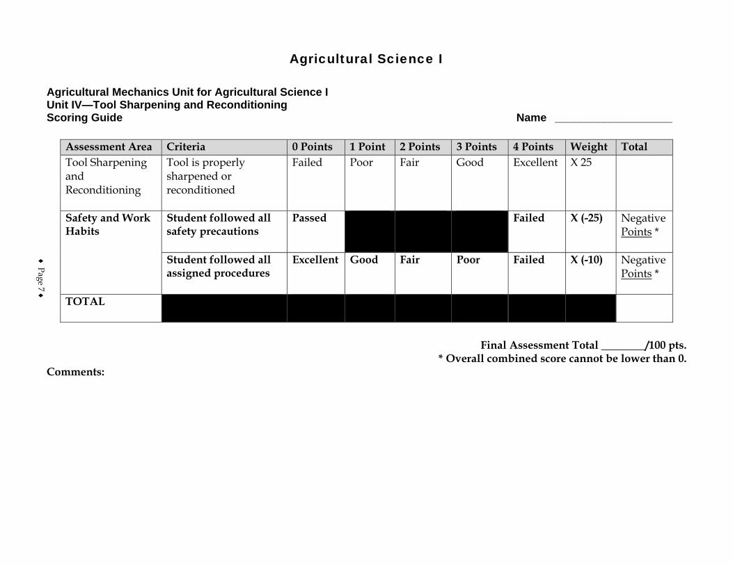
Agricultural Science I
Agricultural Mechanics Unit for Agricultural Science I Unit IV—Tool Sharpening and Reconditioning Scoring Guide Name ___________________
Assessment Area Criteria 0 Points 1 Point 2 Points 3 Points 4 Points Weight Total Tool Sharpening and Reconditioning
Tool is properly sharpened or reconditioned
Failed Poor Fair Good Excellent X 25
Safety and Work Habits
Student followed all safety precautions
Passed Failed X (-25) Negative Points *
Student followed all assigned procedures
Excellent Good Fair Poor Failed X (-10) Negative Points *
TOTAL
Final Assessment Total ________/100 pts.
* Overall combined score cannot be lower than 0. Comments:
♦ Page 7 ♦

♦ Page 8 ♦
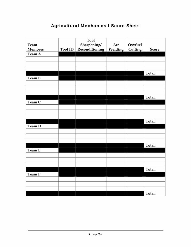
♦ Page 9 ♦
Agricultural Mechanics I Score Sheet
Team Members Tool ID
Tool Sharpening/
Reconditioning Arc
Welding Oxyfuel Cutting Score
Team A Total: Team B Total: Team C Total: Team D Total: Team E Total: Team F Total:

♦ Page 10 ♦
Ag Science I – Ag Mechanics I – Arc Welding Safety and Maintenance Procedures for Arc Welding • Page 1 of 8
Course Agricultural Science I
Unit Agricultural Mechanics I
Subunit Arc Welding
Lesson Safety and Maintenance Procedures for Arc Welding
Estimated Time 2 50-minute blocks Student Outcome
Identify basic safety and maintenance procedures for arc welding. Learning Objectives
1. Identify the safety and health risks associated with arc welding. 2. Explain how electric shock can be avoided when welding. 3. Explain how burns and fire can be avoided when welding. 4. Explain how hazards from arc rays can be avoided when welding. 5. Explain how breathing hazards can be avoided when welding. 6. Describe the care and maintenance required for the arc welding equipment.
Grade Level Expectations
SC/ME/1/H/09-11/d Resources, Supplies & Equipment, and Supplemental Information
Resources 1. PowerPoint Slides
PPt 1 – Protective Clothing for Welding PPt 2 – Protective Eyewear PPt 3 – Respirators Used for Welding
2. Activity Sheet
AS 1 – Arc Welding Safety Presentation 3. Agricultural Mechanics Unit for Agricultural Science I (Student Reference). University of
Missouri-Columbia: Instructional Materials Laboratory, 2002. 4. Curriculum Enhancement for Agricultural Mechanics Unit for Agricultural Science I, “Unit V
- Arc Welding.” University of Missouri-Columbia: Instructional Materials Laboratory, 2004.
Supplemental Information 1. Internet Sites
Arc Welding. Division of Safety and Hygiene of the Ohio Industrial Commission. Vermont Safety Information Resources, Inc. Accessed September 19, 2007, from http://siri.org/library/ind/Welding/arc.html.
Educators Library: Safety. American Welding Society. Accessed September 10, 2007, from http://www.aws.org/cgi-bin/educate/scan/dl=Safety/mp=guide?id=MKJbHy6P&mv_pc=7.
Ag Science I – Ag Mechanics I – Arc Welding Safety and Maintenance Procedures for Arc Welding • Page 2 of 8
Fluegel, L. and B. Rein. “Arc Welding Safety.” University of Arizona Cooperative Extension. National Ag Safety Database. Accessed September 19, 2007, from http://www.cdc.gov/nasd/docs/d000801-d000900/d000873/d000873.html.
National Electrical Manufacturers Association. Accessed September 24, 2007, from http://www.nema.org/.
National Fire Protection Association. Accessed September 24, 2007, from http://www.nfpa.org/.
Welding, Cutting, and Brazing. Occupational Safety and Health Administration. U. S. Department of Labor. Accessed September 19, 2007, from http://www.osha.gov/SLTC/weldingcuttingbrazing/index.html.
2. Print Althouse, A., C. Turnquist, W. Bowditch, and K. Bowditch. Modern Welding. Tinley
Park, IL: Goodheart-Willcox, 2000. Jeffus, L. Welding Principles and Applications. 5th ed. Clifton Park, NY: Thomson-
Delmar Learning, 2004. Phipps, L. and G. Miller. Introduction to Agricultural Mechanics. Upper Saddle River,
NJ: Prentice Hall Interstate, 2004. 3. Electronic Media
Protective Clothing for Welding Safety. Expert Village. Accessed September 24, 2007, from http://www.youtube.com/watch?v=aeUzX2FNLvc.
Smartflix offers a line of videos related to metalworking that can be rented from their Web site. Accessed September 12, 2007, from http://smartflix.com/store/category/115/Metalworking.
Why Not to Weld on Closed Vessels. Expert Village. Accessed September 24, 2007, from http://www.youtube.com/watch?v=cp3DJmC2kW0.
Why Wear a Welding Helmet? Expert Village. Accessed September 24, 2007, from http://www.youtube.com/watch?v=-Eaqe-DSSCg.
Ag Science I – Ag Mechanics I – Arc Welding Safety and Maintenance Procedures for Arc Welding • Page 3 of 8
Instructor Directions Content Outline
Objective 1 Safety and health risks associated with arc welding are discussed at right.
Identify the safety and health risks associated with arc welding.
1. Electric shock - Arc welders produce relatively low
voltage, but they can produce enough to kill a person by electric shock.
2. Burns and fire - The arc produced by an arc welder can reach temperatures in excess of 9,000°F.
3. Burns from arc rays - The welding arc emits rays that can cause first- and second-degree burns of skin within minutes and flash burns of the eyes within seconds. These rays cannot be seen, and their effects are not felt until after exposure has occurred. Reflected light from welding is as dangerous as direct light.
4. Breathing hazards from oxygen displacement and from toxic fumes and gases - The arc, flame, fumes, or gases can reduce or replace oxygen if the area is not adequately ventilated. Toxic fumes and gases given off in the welding process can also pose a hazard.
Objective 2 Although welding can be done with relatively low voltage, it nevertheless poses the danger of electric shock. Discuss ways to avoid shock hazards.
Explain how electric shock can be avoided when welding.
Make sure the welder is installed and hooked up properly. 1. Make sure the welder is properly grounded. Do not
confuse the grounding device with the ground clamp that attaches to the work.
Interest Approach
Have students discuss shop safety procedures they are already familiar with and how these might apply specifically to welding. Then discuss what additional safety procedures they would anticipate needing to take. One example would be protective eye wear. Clear safety glasses are needed when cleaning slag from welds, but shaded lenses are also needed for the actual welding process.
Communicate the Learning Objectives
1. Identify the safety and health risks associated with arc welding. 2. Explain how electric shock can be avoided when welding. 3. Explain how burns and fire can be avoided when welding. 4. Explain how hazards from arc rays can be avoided when welding. 5. Explain how breathing hazards can be avoided when welding. 6. Describe the care and maintenance required for the arc welding equipment.
Ag Science I – Ag Mechanics I – Arc Welding Safety and Maintenance Procedures for Arc Welding • Page 4 of 8
Instructor Directions Content Outline
2. Make sure the power disconnect switch is within close reach of the operator.
3. Make sure the welder is on its own circuit with a fuse or breaker of the appropriate size.
Inspect equipment for damage or a defect. 1. Keep connections tight and clean. Bad connections
can heat up and cause dangerous arcs or melting. 2. Do not use electrode holders that are damaged or
display poor insulation. Disconnect the welder from the power source before making any repairs. Do not change the polarity switch or the current setting while the machine is under a load, that is, when there is an arc between the electrode and the work. Keep clothing, gloves, and equipment dry and do not stand on a wet surface or on a conductive material. 1. Stand on a dry board or a rubber mat if work must be
done in a wet area or if standing must be done on a conductive material, such as steel.
2. Wear rubber gloves under the welding gloves if the area is wet or the operator is perspiring.
Do not change the electrode while wearing wet gloves or standing on a wet surface. Do not put the electrode holder in water to cool it. Do not use water to extinguish an electrical fire or any fire near the welder. Remove the electrode from the holder when work is finished.
Objective 3
The welding arc and the high temperatures it produces can cause burns or fires. Discuss measures to prevent burns and fires. Refer to PPt 1.
Explain how burns and fire can be avoided when welding.
Make the work area as fire resistant as possible. 1. Construct the welding booth of fireproof or fire-
resistant materials, such as metal sheeting or concrete blocks.
2. Keep the work area clean and free of trash, grease, oil,
Ag Science I – Ag Mechanics I – Arc Welding Safety and Maintenance Procedures for Arc Welding • Page 5 of 8
Instructor Directions Content Outline
PPt 1 – Protective Clothing for Welding
and other flammable materials. 3. Keep a fire extinguisher, first-aid kit, and safety
equipment within easy reach. Take precautions when handling hot work pieces. 1. Use tongs or pliers, not hands, to pick up hot metal. 2. Use caution to avoid steam burns when cooling metal
pieces in water. 3. Write the word “HOT” with soapstone or chalk on
the work if a piece of hot metal must be left where others could be in contact with it.
4. Do not walk around the shop holding hot metal. Wear appropriate clothing and safety gear. 1. Wear leather gauntlet-style gloves and high-top
leather shoes to protect the hands and feet. 2. Wear only wool or cotton clothing that is dark and
tightly woven to help protect the skin from fire and to help block arc rays.
3. Do not wear synthetic materials, which can burn readily and give off poisonous gases.
4. Wear only long-sleeved shirts that button at the sleeves and collar. Keep the sleeves and shirt buttoned, including the top button at the collar.
5. Wear pants that come down over the top of the boots and do not have cuffs. Sparks could get caught in the cuffs.
6. Long-sleeved fire-resistant coveralls are recommended. Other types of protective clothing, such as leather aprons and leather sleeves, are also available and should be worn as needed.
7. Do not wear clothing with torn or frayed areas that could leave the skin exposed or could easily catch fire from sparks.
8. Wear safety glasses or goggles when chipping hot slag from welds. Wear additional head and eye protection, such as a flameproof skullcap or face shield, as needed to avoid burns from sparks or hot metal spatter.
9. Do not have items in pockets that could catch fire or explode, such as matches or butane lighters.
Ag Science I – Ag Mechanics I – Arc Welding Safety and Maintenance Procedures for Arc Welding • Page 6 of 8
Instructor Directions Content Outline
Do not attempt to heat, cut, or weld containers such as tanks, drums, and barrels.
Objective 4 Light from the welding arc can burn the eyes within seconds. Discuss procedures for avoiding light burns of the eyes. Refer to PPt 2.
PPt 2 – Protective Eyewear
Explain how hazards from arc rays can be avoided when welding.
Wear a welding helmet with a filter lens classified as no. 10 or higher, depending on the work being done. Consult the manufacturer’s recommendations for appropriate lens. 1. Wear safety glasses if the helmet does not have a lens
made of safety glass. Welding helmets are available in different types, including some that have a flip-up or fixed shaded lens. A flip-up lens allows work such as chipping to be done without removing the helmet. If a flip-up lens helmet is not used, safety glasses must be worn under the helmet.
2. Inspect the helmet and lens assembly to make sure they are undamaged and gaskets fit properly. A damaged helmet or loose gaskets could allow light leaks.
Warn others in the area that you are going to begin welding by saying “Cover up!” Make sure all persons in the welding area are wearing eye protection, such as flash glasses, to avoid eye injury from the reflected light.
Objective 5
Discuss the hazards of inadequate ventilation and exposure to gases and fumes. Refer to PPt 3. After discussing the various safety hazards in welding, assign AS 1 to have students prepare an arc welding safety presentation.
PPt 3 – Respirators Used for Welding
AS 1 – Arc Welding Safety Presentation
Explain how breathing hazards can be avoided when welding.
1. Work in an adequately ventilated area. 2. Use forced ventilation if natural ventilation is not
sufficient. 3. Supplement ventilation as needed with an
appropriate respirator. 4. Clean the metal before welding. Cleaning the metal
helps remove any chemicals that might mix with the fumes produced by welding. It also is safer and easier to establish an arc on a clean surface.
5. Operate engine-powered welders only in well-ventilated areas or with the exhaust vented directly outdoors.
Ag Science I – Ag Mechanics I – Arc Welding Safety and Maintenance Procedures for Arc Welding • Page 7 of 8
Instructor Directions Content Outline Objective 6 Describe the care and maintenance required for the arc
welding equipment.
1. Inspect the electrode holder frequently to be sure it is not damaged or in need of repair.
2. Keep cables free of oil and grease. 3. Run cables so that they will not be damaged or cause
a tripping hazard. In temporary work sites, cables can be protected with C-channel.
4. To avoid damaging the welder, do not shut off or start the welder with the electrode or electrode holder in contact with the work or the welding table. Hang the holder from an insulated hanger when not in use.
5. Keep the welder and electrodes dry. 6. Do not allow dust to accumulate on the transformer
coils. Application:
AS 1 – Arc Welding Safety Presentation
Answers to AS 1 Presentations will vary and grading is at the teacher’s discretion.
Other activities 1. Obtain safety lenses of different shade numbers and
show students the difference in the darkness of each shade. Show them how they can identify the shade number. Instruct students on the safe and proper use of safety lenses.
2. Have students collect additional information about arc welding and arc welding safety and present it to the class. Encourage them to consult a variety of sources. Possible sources include other agricultural mechanics textbooks, the Internet, safety information from manufacturers, and conversations with individuals who weld, either for personal use or professionally. Discuss their findings. If some of the information varies or seems to contradict other information, discuss possible causes for these differences and then identify the safest course of action.
Closure/Summary Hazards of arc welding include electric shock, burns of the skin and eyes, fires, and toxic fumes and gases. Making sure the welder is properly grounded and
Ag Science I – Ag Mechanics I – Arc Welding Safety and Maintenance Procedures for Arc Welding • Page 8 of 8
Instructor Directions Content Outline
hooked up is an important preventive measure, as is wearing protective clothing and other safety gear. Breathing hazards can be avoided by working in a ventilated area and using a respirator as needed. Another safety measure is proper maintenance of the arc welding equipment, including keeping cables free of oil and grease and keeping the welder and electrodes dry.
Evaluation: Quiz Answers: 1. b 2. a 3. a 4. d 5. b 6. b 7. c 8. c 9. a 10. a 11. c 12. b 13. a 14. a 15. c 16. a 17. b 18. b 19. a and b 20. b and d 21. d
Unit V - Arc Welding AS 1 Lesson 1: Safety and Maintenance Name ________________________ for Arc Welding Arc Welding Safety Presentation Objective: Students will identify a safety hazard and ways to prevent it. Directions: Create a slide show using presentation software (e.g., Microsoft PowerPoint, Corel Presentations) about an arc welding safety hazard (electric shock, burns and fire, burns from light rays, or breathing hazards). Complete the following steps in creating the slide show. 1. Create a cover page with a title and your name. 2. In part one of the slide show, identify the safety hazard and provide at least two specific ways that
the welder can be harmed. 3. In part two of the slide show, explain several ways the hazard can be minimized or how an
accident can be prevented. 4. On the last slide, provide a bibliography for the information used to create the show. 5. Present the slide show to the class. Use information from this lesson, reference books at school, and/or access the National Agricultural Safety Database (NASD) web site at http://www.cdc.gov/nasd/menu/topic/machinery_welding.html for more information. If possible, insert relevant graphics to illustrate key points.
Unit V - Arc Welding Name_________________________ Lesson 1: Safety and Maintenance Date__________________________ for Arc Welding
Assessment
Match the type of safety risk with the situation. (Some situations may involve more than one risk.) a. Electric shock b. Burns and fire c. Burns from arc rays d. Breathing hazards 1. The welding booth is littered with trash and there are oil spills on the floor.
2. A worker repairs the welder while it is plugged in. 3. The floor in the welding area has puddles of water. 4. The welder welds in a confined, unventilated space. 5. The welder plans to paint later and stores newspapers and rags in the welding area.
6. The welder uses tongs to pick up hot metal and immerse it in water but does not wear gloves.
7. The welder wears a white long-sleeved shirt that is made of thin cotton. 8. The welder wears a helmet with a filter lens that is cracked. 9. The welding machine is not properly grounded. 10. The cable for the ground clamp has a loose connection. 11. People working near the welding station are wearing clear safety glasses because they only see reflected light from the arc.
12. The welder sets a recently welded project in the work area and does not mark it.
13. The electrode holder becomes hot and the welder immerses it in water. 14. An electrical fire starts near the welding machine and someone pours a bucket of water on the fire.
15. The welder does not warn others in the area before starting to weld. 16. The welder finishes welding and forgets to remove the electrode from the holder.
17. There is no fire extinguisher near the work area. 18. The welder wears pants with cuffs. 19. The welding machine is on the same circuit with a pedestal grinder and power saw.
20. The welder welds a seam in a drum that used to contain grease. 21. The welder does not clean the metal before welding.
Ag Science I – Ag Mechanics I – Arc Welding Parts and Setup for Arc Welding • Page 1 of 7
Course Agricultural Science I
Unit Agricultural Mechanics I
Subunit Arc Welding
Lesson Parts and Setup for Arc Welding
Estimated Time 2 50-minute blocks Student Outcome
Identify the major parts of a shielded metal arc welder. Describe how a shielded metal arc welder works.
Learning Objectives
1. Define welding. 2. Define arc welding and shielded metal arc welding. 3. Identify the major parts of an arc welder. 4. Explain the function of the electrode in arc welding and how the correct electrode is
selected. 5. Explain how current is a factor in arc welding.
Grade Level Expectations
SC/FM/2/F/09-11/b Resources, Supplies & Equipment, and Supplemental Information
Resources 1. PowerPoint Slides
PPt 1 – Shielded Metal Arc Welding PPt 2 – Electrodes PPt 3 – Electrode Classification PPt 4 – Electrode Sizes and Amperage Ranges
2. Agricultural Mechanics Unit for Agricultural Science I (Student Reference). University of Missouri-Columbia: Instructional Materials Laboratory, 2002.
3. Curriculum Enhancement for Agricultural Mechanics Unit for Agricultural Science I, “Unit V - Arc Welding.” University of Missouri-Columbia: Instructional Materials Laboratory, 2004.
Supplemental Information 1. Internet Sites
American Welding Society. Accessed September 24, 2007, from http://www.aws.org/w/a/.
Welding Calculators. Miller Electric Manufacturing Co. Accessed September 24, 2007, from http://www.millerwelds.com/education/calculators/.
2. Print Althouse, A., C. Turnquist, W. Bowditch, and K. Bowditch. Modern Welding. Tinley
Park, IL: Goodheart-Willcox, 2000.
Ag Science I – Ag Mechanics I – Arc Welding Parts and Setup for Arc Welding • Page 2 of 7
Jeffus, L. Welding Principles and Applications. 5th ed. Clifton Park, NY: Thomson-Delmar Learning, 2004.
Phipps, L. and G. Miller. Introduction to Agricultural Mechanics. Upper Saddle River, NJ: Prentice Hall Interstate, 2004.
3. Electronic Media Setting the Amperage: Basic Arc Welding Skills. Expert Village. Accessed
September 25, 2007, from http://www.expertvillage.com/videos/arc-welding-for-beginners-set-amperage.htm.
Smartflix offers a line of videos related to metalworking that can be rented from their Web site. Accessed September 12, 2007, from http://smartflix.com/store/category/115/Metalworking.
What Is Arc Welding: How it Works. Expert Village. Accessed September 25, 2007, from http://www.expertvillage.com/videos/arc-welding-for-beginners-what-is-arc-welding.htm.
Ag Science I – Ag Mechanics I – Arc Welding Parts and Setup for Arc Welding • Page 3 of 7
Instructor Directions Content Outline
Objective 1 Define welding. 1. Welding is a process in which materials are joined by
fusing them together. 2. This is done by the addition of heat or pressure, or a
combination of heat and pressure. 3. It may be done with or without the addition of new
material (filler). Objective 2
PPt 1 – Shielded Metal Arc
Welding
Define arc welding and shielded metal arc welding.
Arc welding refers to procedures that use a discharge of electricity (an arc) to heat materials and join them. 1. It may be done with or without pressure. 2. It may or may not use filler. 3. In this unit, the term “arc welding” will refer to
shielded metal arc welding, but it is useful to know that there are other kinds of arc welding as well.
Shielded metal arc welding (SMAW) uses heat from the arc and filler material deposited from a flux-coated metal rod, called an electrode. 1. It is called “shielded” because a cloud of gases
formed by the burning flux shields the weld as it is being made.
2. Flux and impurities in the metal rise to the top of the weld and form a layer, called slag, that is later chipped away.
Interest Approach
Show students the arc welding station in the shop. Reinforce the previous lesson by reviewing arc welding safety procedures and having students apply them to the equipment they will be using. If desired, the lesson could be taught in the arc welding station, or an arc welding machine could be brought to the front of the class to illustrate the lesson. Electrodes can be shown or handed out to the students to examine.
Communicate the Learning Objectives
1. Define welding. 2. Define arc welding and shielded metal arc welding. 3. Identify the major parts of an arc welder. 4. Explain the function of the electrode in arc welding and how the correct electrode is
selected. 5. Explain how current is a factor in arc welding.
Ag Science I – Ag Mechanics I – Arc Welding Parts and Setup for Arc Welding • Page 4 of 7
Instructor Directions Content Outline
3. SMAW is sometimes referred to by other names. In addition to “arc welding,” it is sometimes called “rod welding” or “stick welding.”
Objective 3
The major parts of a shielded metal arc welder are discussed at right. Refer to the actual welding equipment in the shop when discussing the parts.
Identify the major parts of an arc welder.
Power source - to produce electricity. There are two major types. 1. A motor- or engine-driven alternator or generator to
produce electric current 2. A transformer to change electric current so that it can
be used by the welder Cables - to carry current to the work and back to the welder 1. Cables can be copper or aluminum. 2. Cables are measured by gauge. As the gauge number
goes down, the cable gets larger in diameter 3. In use, cables heat up and may be exposed to impact,
sharp edges, sparks, oil, and other damage. They should be cared for and inspected frequently.
4. Cables must be the right diameter for their length to avoid overheating or voltage drop.
Electrode holder - an insulated handle used to grip the electrode while welding. 1. Electrode holders are available in different sizes for
carrying different amounts of current. 2. Holders should be used at or below their maximum
amperage rating to avoid overheating. 3. To reduce operator fatigue, select the smallest holder
that will safely carry the amperage used. 4. To avoid damaging the holder, do not burn electrodes
too short. Electrodes should be burned down to approximately 2 in. to reduce waste and protect the holder.
5. Holders should be cleaned and worn parts replaced as needed to keep them in working order.
Ground clamp - a clamp connected to a cable and attached to the welding table or the work. It carries current between the work and the welding machine. 1. Clamps are also sized according to the current being
used. Use the correct clamp and be sure that it is
Ag Science I – Ag Mechanics I – Arc Welding Parts and Setup for Arc Welding • Page 5 of 7
Instructor Directions Content Outline
securely attached to avoid overheating. 2. Clamps are available in different configurations,
including C-clamps and swiveling clamps for welds that must be rotated.
Objective 4
PPt 2 – Electrodes PPt 3 – Electrode
Classification
Explain the function of the electrode in arc welding and how the correct electrode is selected.
There are two parts to the electrode. They have different functions in the welding process. 1. A solid metal core - adds filler to the weld as it melts. 2. A flux coating - may do any or all of the following.
a. Adds filler to the weld b. Stabilizes the arc c. Produces a gas shield that protects the weld d. Adds flux, which removes impurities from the
weld that rise to the top, along with the flux, to form a protective layer over the weld called slag
e. Adds alloying elements to improve the weld f. Determines the polarity of the electrode
Electrodes are available in different lengths and diameters. The diameter of an electrode is determined by the diameter of the metal core. The coating is not included. It is important to choose the right electrode for the job. Some, but not all, of the factors for choosing an electrode are listed below. 1. Type of metal being welded and its tensile strength 2. Thickness of the metal 3. Weld position - whether the weld is flat, horizontal,
vertical, or overhead 4. Experience of the welder 5. Rate at which the filler should be added 6. Type of electric current being used
Objective 5
PPt 4 – Electrode Sizes and Amperage Ranges
Explain how current is a factor in arc welding.
Welders can be described by the type of current they use. There are three kinds. 1. AC welders - use alternating current 2. DC welders - use direct current
Ag Science I – Ag Mechanics I – Arc Welding Parts and Setup for Arc Welding • Page 6 of 7
Instructor Directions Content Outline
3. AC/DC welders - can use either alternating or direct current
Alternating current is continuously changing direction. 1. This means the electrode and the work are switching
from positive to negative while the weld is being made.
2. This switching produces even heating and welds of moderate penetration.
Direct current flows one way only, but this direction can be changed, depending on how the welder is set. This is called changing polarity. 1. Changing polarity produces welds with different
characteristics. 2. When the electrode is positive, welds tend to have
deeper penetration of the base metal (the piece being welded).
3. When the electrode is negative, it tends to melt and deposit material faster. This is useful when working with thin metal.
Application:
Other activities 1. Introduce students to welding calculators and
instruct them on their use. A source for welding calculators is Miller Electric at http://www.millerwelds.com/education/calculators/.
2. Number the parts on the arc welding machine in the shop and have students identify each part.
Closure/Summary In welding, materials are fused together by heat, pressure, or a combination of heat and pressure. In shielded metal arc welding, materials are fused by the addition of heat from the arc and filler material from a flux-coated electrode. Factors to consider when choosing an electrode for the welding job include the type of metal being welded, the weld position, and the rate at which the filler should be added. To ensure good-quality welds, cables and electrode holders should be inspected regularly and replaced as needed. Also important is the type of current used by the welder.
Evaluation: Quiz Answers: 1. d 2. a
Ag Science I – Ag Mechanics I – Arc Welding Parts and Setup for Arc Welding • Page 7 of 7
Instructor Directions Content Outline
3. c 4. d 5. SMAW stands for shielded metal arc welding. This
process uses heat from an arc and filler material deposited from a flux-coated metal rod (electrode) to weld.
6. Answers may vary, depending on parts of the welder the instructor discussed in class. Below are four parts covered in the lesson outline. a. Power source (motor or transformer) b. Cables c. Electrode holder d. Ground clamp
7. An electrode is a metal rod that the welder uses to establish an arc between the electrode and the metal. The two parts are the metal core and the flux coating.
8. Students should list three of the following: a. Type of metal being welded and its tensile
strength b. Thickness of the metal c. Weld position (flat, vertical, overhead,
horizontal) d. Experience of the welder e. Rate at which the filler should be added f. Type of electric current being used
9. Answers may vary, depending on the material and amount of detail covered in class. Based on material in the lesson outline, answers should indicate the following. The direction of current flow is changed, which can affect the characteristics of the weld.
Unit V - Arc Welding Name_________________________ Lesson 2: Parts and Setup for Arc Welding Date__________________________
Assessment Circle the letter that corresponds to the correct answer. 1. One end of the ground clamp cable is connected to the work or table and the other end is
connected to the:
a. electrical outlet. b. electrode. c. electrode holder. d. welding machine.
2. Which can damage an electrode holder?
a. Burning an electrode to 1 in. b. Inserting an electrode in its jaw c. Using it below its maximum amperage d. Using a large holder for a small electrode
3. Electrodes are sized by the:
a. overall length. b. length of the flux coating. c. diameter of the metal core. d. diameter of the flux coating.
4. Which statement is correct about an AC welder?
a. It consumes a large amount of electricity. b. It can use either alternating or direct current. c. The direction of the current can be changed on the welder. d. It produces current that is continuously changing direction.
Complete the following short-answer questions. 5. What does SMAW stand for and what does it mean?

6. What are four major parts of the shielded metal arc welder? a. b. c. d.
7. Define an electrode and list its two parts.
8. Provide three factors to consider when choosing an electrode. a. b. c.
9. What happens when the polarity of a welding machine is changed?
Ag Science I – Ag Mechanics I – Arc Welding Basic Use of an Arc Welder • Page 1 of 7
Course Agricultural Science I
Unit Agricultural Mechanics I
Subunit Arc Welding
Lesson Basic Use of an Arc Welder
Estimated Time 4 50-minute blocks Student Outcome
Demonstrate striking an arc. Demonstrate welding common joints.
Learning Objectives
1. Explain how to prepare metal for welding. 2. Explain how to strike an arc. 3. Identify the kinds of beads the arc welder makes. 4. Identify the factors that influence the condition of the bead.
Grade Level Expectations
SC/ME/1/D/09-11/b SC/ME/1/G/09-11/a SC/ME/2/A/09-11/d
SC/ME/2/A/09-11/e SC/FM/2/F/09-11/b Resources, Supplies & Equipment, and Supplemental Information
Resources 1. PowerPoint Slides
PPt 1 – Preparing Metal for Welding PPt 2 – Two Methods of Striking an Arc PPt 3 – Stringer and Weaving Beads PPt 4 – Electrode Angle PPt 5 – Properly and Improperly Formed Beads as a Result of Varying Speed of
Travel PPt 6 – Properly and Improperly Formed Beads as a Result of Varying Current
Setting PPt 7 – Properly and Improperly Formed Beads as a Result of Varying Arc Length PPt 8 – Butt Welding Round Stock in Flat Position PPt 9 – Common Types of Joints
2. Activity Sheets
AS 1 – Running a Bead Using a Shielded Metal Arc Welder (Instructor)
AS 1 – Running a Bead Using a Shielded Metal Arc Welder (Student)
AS 2 – Welding a Butt Joint in Steel Plate in Flat Position (Instructor)
AS 2 – Welding a Butt Joint in Steel Plate in Flat Position (Student)
AS 3 – Welding a Butt Joint in Round Stock in Flat Position (Instructor)
AS 3 – Welding a Butt Joint in Round Stock in Flat Position (Student)
Ag Science I – Ag Mechanics I – Arc Welding Basic Use of an Arc Welder • Page 2 of 7
AS 4 – Welding a Lap Joint in Steel Plate in Flat Position (Instructor)
AS 4 – Welding a Lap Joint in Steel Plate in Flat Position (Student)
AS 5 – Welding a Tee Joint in Steel Plate in Flat Position (Instructor)
AS 5 – Welding a Tee Joint in Steel Plate in Flat Position (Student) 3. Agricultural Mechanics Unit for Agricultural Science I (Student Reference). University of
Missouri-Columbia: Instructional Materials Laboratory, 2002. 4. Curriculum Enhancement for Agricultural Mechanics Unit for Agricultural Science I, “Unit V
- Arc Welding.” University of Missouri-Columbia: Instructional Materials Laboratory, 2004.
Supplies & Equipment See AS 1 through AS 5 for materials and equipment needed to complete the Activity
Sheets. Supplemental Information
1. Print Althouse, A., C. Turnquist, W. Bowditch, and K. Bowditch. Modern Welding. Tinley
Park, IL: Goodheart-Willcox, 2000. Jeffus, L. Welding Principles and Applications. 5th ed. Clifton Park, NY: Thomson-
Delmar Learning, 2004. Phipps, L. and G. Miller. Introduction to Agricultural Mechanics. Upper Saddle River,
NJ: Prentice Hall Interstate, 2004. 2. Electronic Media
How to Strike an Arc: Basic Welding Skills for Beginners. Expert Village. Accessed September 26, 2007, from http://www.expertvillage.com/videos/arc-welding-for-beginners-how-strike-arc.htm.
Running a Bead of Weld: Arc Welding Tips for Beginners. Expert Village. Accessed September 26, 2007, from http://www.expertvillage.com/videos/arc-welding-for-beginners-bead-weld.htm.
Smartflix offers a line of videos related to metalworking that can be rented from their Web site. Accessed September 12, 2007, from http://smartflix.com/store/category/115/Metalworking.
Ag Science I – Ag Mechanics I – Arc Welding Basic Use of an Arc Welder • Page 3 of 7
Instructor Directions Content Outline
Objective 1
PPt 1 – Preparing Metal for Welding
Explain how to prepare metal for welding.
Metal to be welded (the base metal) should be clean. 1. Impurities can reduce the strength of the weld. 2. Chemicals, finishes, or other materials on the surface
can mix with welding fumes to form toxic gases. Methods for cleaning base metal 1. Grinding 2. Wire brushing 3. Sand blasting 4. Approved solvents or detergents Metal 1/4 in. or more in thickness should be beveled before welding to increase the penetration of the weld. Methods for beveling metal 1. Flame cutting 2. Grinding 3. Gouging 4. Machining Bevel designs used in welding 1. Single V-groove 2. Single bevel 3. Single V-groove with backing 4. Single bevel with backing 5. Double V-groove 6. Double bevel
Interest Approach
Discuss the importance of understanding welding procedure and having good welding technique. Show students examples of good and bad welds and point out the differences. Show students cross sections of good and bad welds. Point out the flaws such as voids, slag inclusions, and undercutting and explain how they can be avoided.
Communicate the Learning Objectives
1. Explain how to prepare metal for welding. 2. Explain how to strike an arc. 3. Identify the kinds of beads the arc welder makes. 4. Identify the factors that influence the condition of the bead.
Ag Science I – Ag Mechanics I – Arc Welding Basic Use of an Arc Welder • Page 4 of 7
Instructor Directions Content Outline
Some factors for choosing the bevel 1. Position of the joint 2. Joint design 3. Application of the joint
Objective 2 The first step in welding is being able to strike and maintain an arc. Two methods for striking an arc are covered at right.
PPt 2 – Two Methods of Striking an Arc
Explain how to strike an arc.
1. Scratching method - the electrode is moved a short distance across the base metal at an angle, similar to striking a match, and then brought back down until proper arc length is reached.
2. Tapping method - the electrode is brought straight down until it touches the base metal, lifted up, and brought back down until proper arc length is reached.
3. Correct distance for arc length varies, but is roughly equal to the diameter of the electrode.
4. Once the arc is established, hold it in one place. A small puddle of melted metal will start to form (the weld pool). When the weld pool is the desired size, begin running the bead.
Objective 3
Once a stable arc can be maintained and the weld pool forms, beads can be made.
PPt 3 – Stringer and Weaving Beads
Identify the kinds of beads the arc welder makes.
Stringer beads 1. Made by moving the electrode in a straight line 2. Should be approximately two to three times as wide
as the diameter of the electrode Weaving beads 1. Made by moving the electrode from side to side while
also moving along the line of the joint 2. Can be up to six times the diameter of the electrode in
width Objective 4
Factors that affect the bead are discussed at right. Refer to PPt 4-7. When students have reviewed and discussed arc welding safety and procedures, the instructor versions of AS 1-5 should be used to demonstrate the correct way to strike an arc and make basic welds using a shielded metal arc welder. The student version of these
Identify the factors that influence the condition of the bead.
Correct - A properly formed bead should have evenly spaced semicircular ripples. The bead should be an even width. Electrode angle can vary, but it is generally inclined 10 to 20 degrees in the direction of travel. Right-handed welders usually work best from left to right; left-handed welders from right to left. A welder must be able to “read” the bead and know if it was made correctly. Below are the most common adjustments for improperly formed beads.
Ag Science I – Ag Mechanics I – Arc Welding Basic Use of an Arc Welder • Page 5 of 7
Instructor Directions Content Outline
activities should be assigned to evaluate student competency.
PPt 4 – Electrode Angle
PPt 5 – Properly and Improperly Formed Beads as a Result of Varying Speed of Travel
PPt 6 – Properly and
Improperly Formed Beads as a Result of Varying Current Setting
PPt 7 – Properly and
Improperly Formed Beads as a Result of Varying Arc Length
AS 1 – Running a Bead Using a Shielded Metal Arc Welder
AS 2 – Welding a Butt Joint in Steel Plate in Flat Position
AS 3 – Welding a Butt Joint in Round Stock in Flat Position
AS 4 – Welding a Lap Joint in Steel Plate in Flat Position (Instructor)
AS 5 – Welding a Tee Joint in Steel Plate in Flat Position (Instructor)
Speed of travel 1. Too slow - bead will be too wide and thick; ripples
will appear flattened. 2. Too fast - bead will be too low and narrow; ripples
will appear pointed instead of round. Amperage (current) setting 1. Too low - bead will appear narrow, built up, and
stringy; arc will be hard to strike and keep running. 2. Too high - bead will be too wide and low, with large
amounts of spatter. Length of arc 1. Too short - bead will be built up, with poor
penetration; electrode will tend to stick to the base metal.
2. Too long - bead will be too low, wider than desired, and with little buildup; spatter is likely from metal dropping outside the weld pool.
Ag Science I – Ag Mechanics I – Arc Welding Basic Use of an Arc Welder • Page 6 of 7
Instructor Directions Content Outline Application:
AS 1 – Running a Bead Using a Shielded Metal Arc Welder
AS 2 – Welding a Butt Joint in Steel Plate in Flat Position
AS 3 – Welding a Butt Joint in Round Stock in Flat Position
AS 4 – Welding a Lap Joint in Steel Plate in Flat Position
AS 5 – Welding a Tee Joint in Steel Plate in Flat Position
AS 1 – AS 5 Results will vary.
Other activities 1. Create a display board that has examples of good
joints produced by students. It can be a “wall of fame” that gives recognition to students for a job well done.
2. Obtain a poster that depicts good and bad welds and display it in the classroom. One source is Miller Electric. Material can be ordered on their Web site at http://www.millerwelds.com/interests/instructors/classroom_resources.php.
3. Some beginning welders are hesitant to practice running beads using the actual process. Have these students simulate running a bead with a pencil in the electrode holder before moving on to using the arc welding machine.
4. Perform destructive tests to check the strength and soundness of the joints students have welded. Specific instructions regarding the destructive evaluation process are outlined in Welding Principles and Applications, fifth edition, by Larry Jeffus.
Closure/Summary Methods of cleaning the base metal in preparation for welding include grinding, wire rushing, sand blasting, and washing the metal with appropriate solvents or detergents. The first step in welding is striking an arc. Beads can be made after a stable arc has been achieved. Properly formed beads have evenly spaced semicircular ripples and are of an even width.
Evaluation: Quiz Answers: 1. b 2. a 3. c 4. b 5. d 6. a. Scratching - Moving the electrode a short
distance across the base metal at an angle, similar to striking a match, then bringing it back
down until proper arc length is produced
Ag Science I – Ag Mechanics I – Arc Welding Basic Use of an Arc Welder • Page 7 of 7
Instructor Directions Content Outline
b. Tapping - Bringing the electrode straight down until it touches the base metal, lifting it up, and bringing it back down again (pecking motion) until proper arc length is established.
7. a. Arc length - Distance between the electrode and the base metal b. Bead – Line of electrode filler and base metal
produced as the electrode is moved along the work area.
8. a. Speed of travel of the electrode b. Amperage (current) setting c. Arc length
9. a. Butt - Two pieces of metal are positioned parallel to each other with a gap between them and the edges are welded together.
b. Fillet - Two pieces of metal are welded together at a 90-degree angle.
Unit V - Arc Welding AS 1 (Instructor) Lesson 3: Basic Use of an Arc Welder
Running a Bead Using a Shielded Metal Arc Welder Objective: Students will observe how to run a bead using a shielded metal arc welder. Directions: Use an arc welder to run a bead. If desired, demonstrate common adjustments necessary to maintain the arc and correctly run a bead. Materials and Equipment: SMAW machine and accessories Chipping hammer Wire brush Helmet*
Safety glasses or goggles Leather gloves and any other protective clothing recommended
by instructor SMAW electrode(s), selected by instructor Mild steel plate(s), selected by instructor
* Everyone participating in or observing the demonstration should wear appropriate protective eyewear. Procedure: 1. As needed, review PPt 4 through 7 on the arc welding procedure and properly and improperly
formed beads before beginning. 2. Inspect equipment, materials, and work area to ensure safe and correct operation. 3. Wear appropriate face protection and protective clothing. 4. Position the plate on the worktable and attach a ground clamp to the plate or the table. 5. Set up and turn on the machine. 6. Place an electrode in the electrode holder at a 90-degree angle. 7. Position electrode close to the desired starting point, being careful not to strike an arc. 8. Cover up and remind those in the area to do so as well. 9. Demonstrate how to strike an arc, using the scratching and tapping techniques. 10. If desired, demonstrate what happens when the electrode gets frozen to the base metal and the
proper steps for freeing it. 11. If desired, demonstrate the effects of speed, current setting, and length of arc on the bead by
varying these factors and showing students the results. 12. Starting at the top corner of the plate, strike an arc. 13. Run a bead across the length of the plate, watching the weld pool and feeding the electrode at a
steady rate, at roughly a 20-degree angle in the direction of travel. 14. At the edge of the plate, lift the electrode gradually to avoid leaving a crater in the bead and
break the arc. 15. Return to the starting point, strike an arc, and run a bead below and parallel to the first one. 16. Repeat as needed to demonstrate the correct technique to students. 17. Remove the slag with the chipping hammer and wire brush. 18. Remove the electrode from the holder and observe safety, shutdown, and cleanup procedures. 19. Assign AS 1 to be performed by students.
Unit V - Arc Welding AS 1 (Student) Lesson 3: Basic Use of an Arc Welder
Running a Bead Using a Shielded Metal Arc Welder Objective: Students will run a bead using a shielded metal arc welder. Directions: Students will use an arc welder to run a stringer bead on mild steel. Materials and Equipment: SMAW machine and accessories Chipping hammer Wire brush Helmet*
Safety glasses or goggles Leather gloves and any other protective clothing recommended
by instructor SMAW electrode(s), selected by instructor Mild steel plate(s), selected by instructor
* Everyone participating in or observing the demonstration should wear appropriate protective eyewear. Procedure: 1. Inspect equipment, materials, and work area to ensure safe and correct operation. 2. Wear appropriate face protection and protective clothing. 3. Position the plate on the worktable and attach a ground clamp to the plate or the table. 4. Set up and turn on the machine. 5. Place an electrode in the electrode holder at a 90-degree angle. 6. Position electrode close to the desired starting point, being careful not to strike an arc. 7. Cover up and remind those in the area to do so as well. 8. Starting at the top corner of the plate, strike an arc and lower it to the proper length. Use
preferred technique or the technique assigned by the instructor. 9. Run a bead across the length of the plate, watching the weld pool and feeding the electrode
at a steady rate, at roughly a 20-degree angle in the direction of travel. 10. At the edge of the plate, lift the electrode gradually to avoid leaving a crater in the bead and
break the arc. 11. Return to the starting point, strike an arc, and run a bead below and parallel to the first one. 12. Repeat until the plate is filled. 13. Remove the slag with the chipping hammer and wire brush. 14. Turn the plate over and repeat steps 8 through 13. 15. Remove the electrode from the holder and observe safety, shutdown, and cleanup
procedures. Return materials and equipment to their assigned places. 16. When the plate is safe to handle, compare results with examples discussed in class, if
instructed to do so. 17. Turn in work to be graded by instructor.
Unit V - Arc Welding AS 2 (Instructor) Lesson 3: Basic Use of an Arc Welder
Welding a Butt Joint in Steel Plate in Flat Position Objective: Students will observe how to weld a butt joint in steel plate using a shielded metal arc welder. Directions: Use an arc welder to weld a butt joint in steel plate. Materials and Equipment: SMAW machine and accessories Chipping hammer Wire brush Helmet* Safety glasses or goggles Leather gloves and any other protective clothing recommended by instructor SMAW electrode(s), selected by instructor Mild steel plates, selected by instructor * Everyone participating in or observing the demonstration should wear appropriate protective eyewear. Procedure: 1. Review PPt 1 Preparing Metal for Welding or other material covered on preparing base metals as
needed. 2. Inspect equipment, materials, and work area to ensure safe and correct operation. 3. If necessary, bevel plates to be welded. 4. Wear appropriate face protection and protective clothing. 5. Position the plates on the worktable and attach a ground clamp to the work or the table. 6. Set up and turn on the machine. 7. Place an electrode in the electrode holder at a 90-degree angle. 8. Position electrode close to the desired starting point, being careful not to strike an arc. 9. Cover up and remind those in the area to do so as well. 10. Strike an arc. 11. Tack weld both ends of the joint using about 1/4 in. of weld. 12. Straighten the plates. A hammer can be used if needed to set them back in alignment. 13. Clean slag from the tack welds. 14. Strike an arc and weld the joint, using preferred weaving technique, if needed. 15. Remove the slag from the weld with the chipping hammer and wire brush. 16. Run additional passes if needed to complete the weld, cleaning the weld between each pass. 17. Clean the final pass and inspect the weld. The completed weld should blend evenly with the base,
should have uniform ripples for the length of the weld, should go through to the bottom of the base, and fill the groove completely from one edge to the other.
18. Remove the electrode from the holder and observe safety, shutdown, and cleanup procedures. 19. Assign AS 2 to be performed by students.
Unit V - Arc Welding AS 2 (Student) Lesson 3: Basic Use of an Arc Welder
Welding a Butt Joint in Steel Plate in Flat Position Objective: Students will weld a butt joint in steel plate using a shielded metal arc welder. Directions: Students will use an arc welder to weld a butt joint in steel plate in flat position. Materials and Equipment: SMAW machine and accessories Chipping hammer Wire brush Helmet* Safety glasses or goggles Leather gloves and any other protective clothing recommended by instructor SMAW electrode(s), selected by instructor Mild steel plates, selected by instructor * Everyone participating in or observing the demonstration should wear appropriate protective eyewear. Procedure: 1. Inspect equipment, materials, and work area to ensure safe and correct operation. 2. If necessary, clean and bevel plates to be welded. 3. Wear appropriate face protection and protective clothing. 4. Position the plates on the worktable and attach a ground clamp to the work or the table. 5. Set up and turn on the machine. 6. Place an electrode in the electrode holder at a 90-degree angle. 7. Position electrode close to the desired starting point, being careful not to strike an arc. 8. Cover up and remind those in the area to do so as well. 9. Strike an arc. 10. Tack weld both ends of the joint using about 1/4 in. of weld. 11. Straighten the plates. A hammer can be used if needed to set them back in alignment. 12. Clean slag from the tack welds. 13. Strike an arc and weld the joint, using weaving technique as determined by instructor if needed. 14. Remove the slag from the weld with the chipping hammer and wire brush. 15. Run additional passes if needed to complete the weld, cleaning the weld between each pass. 16. Clean the final pass and inspect the weld. The completed weld should blend evenly with the base,
should have uniform ripples for the length of the weld, should go through to the bottom of the base, and fill the groove completely from one edge to the other.
17. Remove the electrode from the holder and observe safety, shutdown, and cleanup procedures. Return materials and equipment to their assigned places.
18. Turn in work to be graded by instructor.
Unit V - Arc Welding AS 3 (Instructor) Lesson 3: Basic Use of an Arc Welder
Welding a Butt Joint in Round Stock in Flat Position Objective: Students will observe how to weld a butt joint in round stock in flat position using a shielded metal arc welder. Directions: Use an arc welder to weld a butt joint in round stock. Materials and Equipment: SMAW machine and accessories Chipping hammer Wire brush Helmet* Safety glasses or goggles Leather gloves and any other protective clothing recommended by instructor SMAW electrode(s), selected by instructor 2 pieces of 1/2-in. round bar stock, length determined by instructor 1 piece of angle iron to support the stock * Everyone participating in or observing the demonstration should wear appropriate protective eyewear. Procedure: 1. Inspect equipment, materials, and work area to ensure safe and correct operation. 2. Bevel the ends of the pieces to be welded at a 30-degree angle on opposite sides of the stock.
When the two pieces are butted together, they should form a 60-degree angle on the top and the bottom. Refer to PPt 8 Butt Welding Round Stock in Flat Position and review PPt 1 Preparing Metal for Welding or other material covered on preparing base metals as needed.
3. Wear appropriate face protection and protective clothing. 4. Position the pieces in the angle iron on the worktable with a gap of 1/16 to 1/8 in. between them
and attach a ground clamp to the stock or the table. 5. Set up and turn on the machine. 6. Place an electrode in the electrode holder at a 90-degree angle. 7. Position electrode close to the desired starting point, being careful not to strike an arc. 8. Cover up and remind those in the area to do so as well. 9. Strike an arc. 10. Weld a bead at the bottom of the groove and clean the weld. 11. Turn the pieces over and repeat. 12. Continue adding beads, cleaning them, and rotating the stock. It is important to rotate the stock to
avoid warping. 13. If the weld gets red hot, allow it to cool before running another bead. 14. Run additional passes as needed to complete the weld, cleaning the weld between each pass and
cleaning after the final pass. 15. Remove the electrode from the holder and observe safety, shutdown, and cleanup procedures. 16. Assign AS 3 to be performed by students.
Unit V - Arc Welding AS 3 (Student) Lesson 3: Basic Use of an Arc Welder
Welding a Butt Joint in Round Stock in Flat Position Objective: Students will weld a butt joint in round stock in flat position using a shielded metal arc welder. Directions: Students will use an arc welder to weld a butt joint in round stock. Materials and Equipment: SMAW machine and accessories Chipping hammer Wire brush Helmet* Safety glasses or goggles Leather gloves and any other protective clothing recommended by instructor SMAW electrode(s), selected by instructor 2 pieces of 1/2-in. round bar stock, length determined by instructor 1 piece of angle iron to support the stock * Everyone participating in or observing the demonstration should wear appropriate protective eyewear. Procedure: 1. Inspect equipment, materials, and work area to ensure safe and correct operation. 2. Bevel the ends of the pieces to be welded at a 30-degree angle on opposite sides of the stock.
When the two pieces are butted together, they should form a 60-degree angle on the top and the bottom.
3. Wear appropriate face protection and protective clothing. 4. Position the pieces in the angle iron on the worktable with a gap of 1/16 to 1/8 in. between
them and attach a ground clamp to the stock or the table. 5. Set up and turn on the machine. 6. Place an electrode in the electrode holder at a 90-degree angle. 7. Position electrode close to the desired starting point, being careful not to strike an arc. 8. Cover up and remind those in the area to do so as well. 9. Strike an arc. 10. Weld a bead at the bottom of the groove and clean the weld. 11. Turn the pieces over and repeat. 12. Continue adding beads, cleaning them, and rotating the stock. It is important to rotate the
stock to avoid warping. 13. If the weld gets red hot, allow it to cool before running another bead. 14. Run additional passes as needed to complete the weld, cleaning the weld between each pass
and cleaning after the final pass. 15. Remove the electrode from the holder and observe safety, shutdown, and cleanup
procedures. Return materials and equipment to their assigned places. 16. Turn in work to be graded by instructor.
Unit V - Arc Welding AS 4 (Instructor) Lesson 3: Basic Use of an Arc Welder
Welding a Lap Joint in Steel Plate in Flat Position Objective: Students will observe how to weld a lap joint in steel plate in flat position using a shielded metal arc welder. Directions: Use an arc welder to weld a lap joint in steel plate. Materials and Equipment: SMAW machine and accessories Chipping hammer Wire brush Helmet* Safety glasses or goggles Leather gloves and any other protective clothing recommended by instructor SMAW electrode(s), selected by instructor Mild steel plates, selected by instructor * Everyone participating in or observing the demonstration should wear appropriate protective eyewear. Procedure: 1. Discuss fillet welds with students. Fillet welds are welds in which the parts come together to
form a right angle. They are used in lap joints, tee joints, and corners. Refer to PPt 9 Common Types of Joints. Remind students that heat builds up during welding but that it is not always evenly distributed. Weaving the bead can help control heat distribution. Discuss or review any additional material over fillet joints as needed.
2. Inspect equipment, materials, and work area to ensure safe and correct operation. 3. Wear appropriate face protection and protective clothing. 4. Position the pieces and attach a ground clamp to the stock or the table. 5. Set up and turn on the machine. 6. Place an electrode in the electrode holder at a 90-degree angle. 7. Position electrode close to the desired starting point, being careful not to strike an arc. 8. Cover up and remind those in the area to do so as well. 9. Strike an arc. 10. Holding the electrode holder at a 45-degree angle, tack weld the pieces. 11. Clean slag from the tack welds. 12. Holding the electrode holder at a 45-degree angle, weld the joint. Use a weaving bead if
necessary. 14. Run additional passes if needed to complete the weld, cleaning the weld between each pass. 15. Clean the final pass and inspect the weld. 16. Repeat on the other side if desired. 17. Remove the electrode from the holder and observe safety, shutdown, and cleanup procedures. 18. Assign AS 4 to be performed by students.
Unit V - Arc Welding AS 4 (Student) Lesson 3: Basic Use of an Arc Welder
Welding a Lap Joint in Steel Plate in Flat Position Objective: Students will weld a lap joint in steel plate in flat position using a shielded metal arc welder. Directions: Students will use an arc welder to weld a lap joint in steel plate. Materials and Equipment: SMAW machine and accessories Chipping hammer Wire brush Helmet* Safety glasses or goggles Leather gloves and any other protective clothing recommended by instructor SMAW electrode(s), selected by instructor Mild steel plates, selected by instructor * Everyone participating in or observing the demonstration should wear appropriate protective eyewear. Procedure: 1. Inspect equipment, materials, and work area to ensure safe and correct operation. 2. Wear appropriate face protection and protective clothing. 3. Position the pieces as directed by the instructor and attach a ground clamp to the stock or
the table. 4. Set up and turn on the machine. 5. Place an electrode in the electrode holder at a 90-degree angle. 6. Position electrode close to the desired starting point, being careful not to strike an arc. 7. Cover up and remind those in the area to do so as well. 8. Strike an arc. 9. Holding the electrode holder at a 45-degree angle, tack weld the pieces. 10. Clean slag from the tack welds. 11. Holding the electrode holder at a 45-degree angle, weld the joint. Use a weaving bead if
necessary. 12. Run additional passes if needed to complete the weld, cleaning the weld between each pass. 13. Clean the final pass and inspect the weld. 14. Repeat on the other side if instructed to do so. 15. Remove the electrode from the holder and observe safety, shutdown, and cleanup
procedures. Materials and equipment should be returned to their assigned places. 16. Turn in work to be graded by instructor.
Unit V - Arc Welding AS 5 (Instructor) Lesson 3: Basic Use of an Arc Welder
Welding a Tee Joint in Steel Plate in Flat Position Objective: Students will observe how to weld a tee joint in steel plate in flat position using a shielded metal arc welder. Directions: Use an arc welder to weld a tee joint in steel plate. Materials and Equipment: SMAW machine and accessories Chipping hammer Wire brush Helmet* Safety glasses or goggles Leather gloves and any other protective clothing recommended by instructor SMAW electrode(s), selected by instructor Mild steel plates, selected by instructor * Everyone participating in or observing the demonstration should wear appropriate protective eyewear. Procedure: 1. Refer to PPt 9 Common Types of Welds or review any material on fillet welds or tee joints as
needed. 2. Inspect equipment, materials, and work area to ensure safe and correct operation. 3. Wear appropriate face protection and protective clothing. 4. Position the pieces and attach a ground clamp to the stock or the table. Clamps or firebrick can be
used to hold or steady the pieces if needed. 5. Set up and turn on the machine. 6. Place an electrode in the electrode holder at a 90-degree angle. 7. Position electrode close to the desired starting point, being careful not to strike an arc. 8. Cover up and remind those in the area to do so as well. 9. Strike an arc, using preferred technique. 10. Holding the electrode holder at a 45-degree angle, tack weld the pieces. 11. Clean slag from the tack welds. 12. Square pieces to form a 90-degree angle if needed. 13. Holding the electrode holder at a 45-degree angle, weld the joint. Use a weaving bead if necessary. 14. If both sides are to be welded, turn the piece around and run a bead on the other side and clean it.
Alternating passes will help reduce the chance of distorting the metal. 15. Run additional passes if needed to complete the weld, cleaning the weld between each pass and
alternating sides. 16. Clean the final pass and inspect the weld. 17. Remove the electrode from the holder and observe safety, shutdown, and cleanup procedures. 18. Assign AS 5 to be performed by students.
Unit V - Arc Welding AS 5 (Student) Lesson 3: Basic Use of an Arc Welder
Welding a Tee Joint in Steel Plate in Flat Position Objective: Students will weld a tee joint in steel plate in flat position using a shielded metal arc welder. Directions: Students will use an arc welder to weld a tee joint in steel plate. Materials and Equipment:
SMAW machine and accessories Chipping hammer Wire brush Helmet* Safety glasses or goggles Leather gloves and any other protective clothing recommended by instructor SMAW electrode(s), selected by instructor Mild steel plates, selected by instructor * Everyone participating in or observing the demonstration should wear appropriate protective eyewear. Procedure: 1. Inspect equipment, materials, and work area to ensure safe and correct operation. 2. Wear appropriate face protection and protective clothing. 3. Position the pieces as directed by instructor and attach a ground clamp to the stock or the table.
Clamps or firebrick can be used to hold or steady the pieces if needed. 4. Set up and turn on the machine. 5. Place an electrode in the electrode holder at a 90-degree angle. 6. Position electrode close to the desired starting point, being careful not to strike an arc. 7. Cover up and remind those in the area to do so as well. 8. Strike an arc. 9. Holding the electrode holder at a 45-degree angle, tack weld the pieces. 10. Clean slag from the tack welds. 11. Square pieces to form a 90-degree angle if needed. 12. Holding the electrode holder at a 45-degree angle, weld the joint. Use a weaving bead if
necessary. 13. If both sides are to be welded, turn the piece around and run a bead on the other side and clean
it. Alternating passes will help reduce the chance of distorting the metal. 14. Run additional passes if needed to complete the weld, cleaning the weld between each pass and
alternating sides. 15. Clean the final pass and inspect the weld. 16. Remove the electrode from the holder and observe safety, shutdown, and cleanup procedures.
Materials and equipment should be returned to their assigned places. 17. Turn in work to be graded by instructor.
Unit V - Arc Welding Name_________________________ Lesson 3: Basic Use of an Arc Welder Date__________________________
Assessment Circle the letter that corresponds to the correct answer. 1. One step in preparing to weld is:
a. running a weaving bead. b. cleaning the metal to be welded. c. running a stringer bead. d. beveling metal that is less than 1/4 in. thick.
2. The correct distance for arc length is roughly equal to: a. the diameter of the electrode. b. the thickness of the base metal. c. half the thickness of the base metal. d. one third of the gap in the joint. 3. A correct statement about a stringer bead is that it:
a. is produced by moving the electrode from side to side. b. is commonly used for optimum penetration at weld edges. c. should be approximately two to three times as wide as the electrode diameter. d. should be approximately six times as wide as the electrode diameter.
4. A correct statement about a weaving bead is that it is:
a. the bead that most welders learn first. b. commonly used when welding deep or wide areas. c. produced by moving the electrode forward and up and down at the same time. d. produced by moving the electrode forward in a straight line.
5. One characteristic of a good bead is ripples that are:
a. flattened. b. pointed. c. rectangular. d. semicircular.

Complete the following short-answer questions. 6. Describe the following methods of striking an arc.
a. Scratching - b. Tapping -
7. Define the following terms.
a. Arc length - b. Bead -
8. Name the three variables discussed that can affect the quality of the bead.
a. b. c.
9. Describe how the joints listed below are made.
a. Butt - b. Fillet -
♦ Page 1 ♦
Agricultural Science I Curriculum Guide: Agricultural Mechanics Unit for Agricultural Science I Unit: V. Arc Welding Unit Objective:
Students will apply principles of shielded metal arc welding by making common flat position welds as part of a welding contest.
Show-Me Standards: 2.5, CA3 References:
Agricultural Mechanics Unit for Agricultural Science I. University of Missouri-Columbia, Instructional Materials Laboratory, 2002. American Welding Society. Accessed November 18, 2003, from http://www.aws.org/. ESAB Knowledge Centre. ESAB. Accessed November 25, 2003, from http://www.esab.com/. Hobart Institute of Welding Technology. Accessed November 17, 2003, from http://www.welding.org/. Lincoln Electric. Accessed November 18, 2003, from http://www.lincolnelectric.com/. Machinery Safety: Welding. National Ag Safety Database. Accessed November 17, 2003, from http://www.cdc.gov/nasd/menu/topic/machinery_welding.html. Miller Electric. Accessed November 18, 2003, from http://www.millerwelds.com/. Missouri CDE Handbook. Accessed November 14, 2003, from http://www.dese.mo.gov/divcareered/ag_cde_guidelines.htm. Missouri FFA Agricultural Mechanics Career Development Event. Accessed November 19, 2003, from http://web.missouri.edu/~pavt0689/statecon.html.
Agricultural Science I
♦ Page 2 ♦
Instructional Strategies/Activities: • Students will engage in study questions in lessons 1 through 3. • Students will complete AS 1.1, Arc Welding Safety Presentation; AS 3.1,
Running a Bead Using a Shielded Metal Arc Welder; AS 3.2, Welding a Butt Joint in Steel Plate in Flat Position; AS 3.3, Welding a Butt Joint in Round Stock in Flat Position; AS 3.4, Welding a Lap Joint in Steel Plate in Flat Position; and AS 3.5, Welding a Tee Joint in Steel Plate in Flat Position.
• Additional activities that relate to the unit objective can be found under the heading “Other Activities” in the following locations: p. V-5 (2, 3), p. V-21 (2, 3), and p. V-37 (2, 3, 5).
Performance-Based Assessment:
Students will be divided into groups. The groups will represent teams and will participate in a welding contest that is similar to the welding portion of the Agricultural Mechanics Career Development Event. Each student will use a shielded metal arc welder to make common flat position welds presented in the unit and discussed in class. Assessment will be based on the ability to safely and correctly perform common welding procedures using a shielded metal arc welder.

Agricultural Science I
♦ Page 3 ♦
Agricultural Mechanics Unit for Agricultural Science I Unit V—Arc Welding Instructor Guide The instructor should assign the performance-based assessment activity at the beginning of the unit. Students will work toward completing the activity as they progress through the unit lessons. The assessment activity will be due at the completion of the unit. 1. Use or adapt the activity sheets found in the unit to assess student
competency at welding. Review or supplement these activities as needed, based on student mastery of the procedures and equipment the students will be using. NOTE: Students should only complete this performance-based activity if they have mastered all the relevant competencies and have the instructor’s permission to perform the activity.
2. For the performance-based assessment activity, have students apply the skills and procedures discussed in the unit by participating in a welding contest.
3. Divide the class into groups and assign students a series of welding
procedures to perform, such as welding a butt joint, lap joint, and tee joint in steel plate in flat position. a. Each student should perform all of the assigned procedures. b. Assign students welding procedures that they have mastered as part of
the instructional activities for this unit. 4. This activity will help prepare students for the arc welding portion of the
Agricultural Mechanics Career Development Event. a. Explain or review event guidelines as needed. b. Refer to the Missouri CDE Handbook for guidelines regarding the
Agricultural Mechanics Career Development Event. The Missouri CDE Handbook is available from the Missouri Department of Elementary and Secondary Education at http://www.dese.mo.gov/divcareered/ag_cde_guidelines.htm.
5. Have students perform the assigned welding procedures.
a. Performance in the welding contest will determine the student’s individual score.
b. Combine the individual scores of the group members to determine the team score for each group.
6. The final assessment score will be based on the ability to safely and correctly
perform the assigned welding procedures.
Agricultural Science I
♦ Page 4 ♦
7. Present an appropriate award to the high-scoring team and individual, if desired.
8. NOTE: The following units in this curriculum guide also include material and
competencies that are addressed by the Agricultural Mechanics Career Development Event: Unit I, Common Hand Tools; Unit IV, Tool Sharpening and Reconditioning; and Unit VI, Oxyfuel Cutting. Some or all of the performance-based assessment activities for these units could be combined to form a mini Agricultural Mechanics Career Development Event, if desired. To conduct a mini Agricultural Mechanics Career Development Event, maintain the same student groups for all of the performance-based assessment activities. An expanded score sheet is included at the end of each of these units that can be used to track individual and group performance in the mini CDE.
9. ADDITIONAL ACTIVITIES:
a. Create a display board using correctly made examples of each type of weld to be performed by the class. Have students compare their welds with the correctly made examples.
b. Create a display board using the students’ best welds. Possible display board themes include the following: each student’s best weld, the best example of each type of weld performed by the class, and the best weld of the week.
c. Perform destructive tests to check the strength and soundness of welds students have made.
Agricultural Science I
♦ Page 5 ♦
Agricultural Mechanics Unit for Agricultural Science I Unit V—Arc Welding Student Handout 1. The instructor will divide the class into groups and give you a series of welds
to perform in a welding contest. 2. Your group will compete in the contest as a team. 3. Perform the assigned welds.
Wear appropriate safety equipment at all times. Follow all assigned safety procedures. You can lose points for not
following safety precautions and other assigned procedures. Inspect the equipment, materials, and work area to ensure safe and correct
operation. Perform the welds using the assigned procedure. Inspect your work. Follow shutdown and cleanup procedures and return all equipment and
materials to their assigned places. Turn in your work to the instructor.
4. Your final assessment score will be based on your ability to safely and
correctly perform the assigned welding procedures.

Agricultural Science I
♦ Page 6 ♦
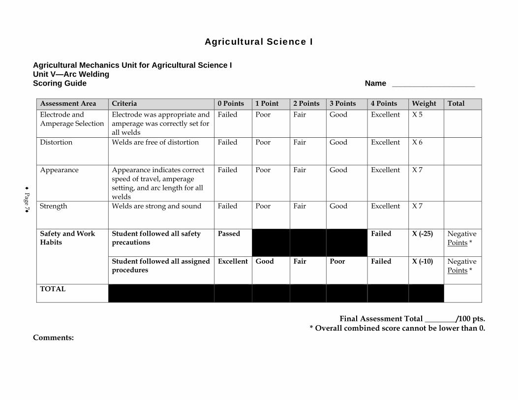
Agricultural Science I
Agricultural Mechanics Unit for Agricultural Science I Unit V—Arc Welding Scoring Guide Name ___________________
Assessment Area Criteria 0 Points 1 Point 2 Points 3 Points 4 Points Weight Total Electrode and Amperage Selection
Electrode was appropriate and amperage was correctly set for all welds
Failed Poor Fair Good Excellent X 5
Distortion Welds are free of distortion Failed Poor Fair Good Excellent X 6
Appearance Appearance indicates correct speed of travel, amperage setting, and arc length for all welds
Failed Poor Fair Good Excellent X 7
Strength Welds are strong and sound Failed Poor Fair Good Excellent X 7
Safety and Work Habits
Student followed all safety precautions
Passed Failed X (-25) Negative Points *
Student followed all assigned procedures
Excellent Good Fair Poor Failed X (-10) Negative Points *
TOTAL
Final Assessment Total ________/100 pts.
* Overall combined score cannot be lower than 0. Comments:
♦ Page 7♦

♦ Page 8 ♦

♦ Page 9 ♦
Agricultural Mechanics I Score Sheet
Team Members Tool ID
Tool Sharpening/
Reconditioning Arc
Welding Oxyfuel Cutting Score
Team A Total: Team B Total: Team C Total: Team D Total: Team E Total: Team F Total:

♦ Page 10 ♦
Ag Science I – Ag Mechanics I – Oxyfuel Cutting Safety in Oxyfuel Cutting • Page 1 of 6
Course Agricultural Science I
Unit Agricultural Mechanics I
Subunit Oxyfuel Cutting
Lesson Safety in Oxyfuel Cutting
Estimated Time 50 minutes Student Outcome
Identify safety procedures for cutting with oxyfuel. Learning Objectives
1. Identify the protective clothing that should be worn for oxyfuel cutting. 2. List the safety procedures that should be observed in the work area. 3. List the safety procedures that should be observed when using the oxyfuel outfit.
Grade Level Expectations
Resources, Supplies & Equipment, and Supplemental Information
Resources 1. PowerPoint Slides
PPt 1 – Protective Gear and Clothing for Oxyfuel PPt 2 – Storing and Moving Gas Cylinders PPt 3 – Oxyfuel Safety Procedures
2. Agricultural Mechanics Unit for Agricultural Science I (Student Reference). University of Missouri-Columbia: Instructional Materials Laboratory, 2002.
3. Curriculum Enhancement for Agricultural Mechanics Unit for Agricultural Science I, “Unit VI - Oxyfuel Cutting.” University of Missouri-Columbia: Instructional Materials Laboratory, 2004.
Supplemental Information 1. Internet Sites
Educators Library: Safety. American Welding Society. Accessed September 10, 2007, from http://www.aws.org/cgi-bin/educate/scan/dl=Safety/mp=guide?id=MKJbHy6P&mv_pc=7.
Gailey, D. W. “Backfires, Flashbacks, and Flashback Arrestors.” Welding Magazine, January 2004. Accessed September 26, 2007, from http://www.weldingmag.com/323/Issue/Article/False/11305/Issue.
Gas Welding Safety. Ohio State University Extension. National Ag Safety Database. Accessed September 26, 2007, from http://www.cdc.gov/nasd/docs/d001601-d001700/d001691/d001691.html.
National Fire Protection Association. Accessed September 24, 2007, from http://www.nfpa.org/.
Ag Science I – Ag Mechanics I – Oxyfuel Cutting Safety in Oxyfuel Cutting • Page 2 of 6
Welding, Cutting, and Brazing. Occupational Safety and Health Administration. U. S. Department of Labor. Accessed September 26, 2007, from http://www.osha.gov/SLTC/weldingcuttingbrazing/index.html.
2. Print Althouse, A., C. Turnquist, W. Bowditch, and K. Bowditch. Modern Welding. Tinley
Park, IL: Goodheart-Willcox, 2000. Jeffus, L. Welding Principles and Applications. 5th ed. Clifton Park, NY: Thomson-
Delmar Learning, 2004. Phipps, L. and G. Miller. Introduction to Agricultural Mechanics. Upper Saddle River,
NJ: Prentice Hall Interstate, 2004. 3. Electronic Media
Acetylene Explosion. Demonstration video. Accessed on September 26, 2007, from http://www.youtube.com/watch?v=X1LwYJ8pDhc.
Smartflix offers a line of videos related to metalworking that can be rented from their Web site. Accessed September 12, 2007, from http://smartflix.com/store/category/115/Metalworking.
Smith Equipment offers a safety video that can be ordered from their Web site. Accessed September 12, 2007, from http://www.smithequipment.com/litreq/safety.htm.
Ag Science I – Ag Mechanics I – Oxyfuel Cutting Safety in Oxyfuel Cutting • Page 3 of 6
Instructor Directions Content Outline
Objective 1
PPt 1 – Protective Gear
and Clothing for Oxyfuel
Identify the protective clothing that should be worn for oxyfuel cutting.
Leather gauntlet-style gloves and high-top leather shoes should be worn to protect the hands and feet. Clothing should be wool or cotton. It should be dark and tightly woven, which helps block light rays. Shirts should be long sleeved and worn with the sleeves and top collar button buttoned. Pants should come down over the tops of the boots and be cuffless to avoid catching sparks. Other protective clothing and equipment, such as leather aprons and leather sleeves, are also available and should be worn as needed. Avoid clothing with tears or frayed areas that can leave skin exposed or easily catch fire by sparks. Avoid synthetic materials, which can burn readily and give off poisonous gases. Wear welding goggles with filter lenses appropriate for the work being done. Lenses with a shade number between 4 and 6 are common for oxyfuel cutting. Consult manufacturer’s recommendations. 1. Expensive filter lenses can be protected with clear
cover plates. 2. Wear safety glasses under the welding goggles to
protect eyes from flying debris.
Interest Approach
Introduce the topic of oxyfuel safety by giving students a tour of the oxyfuel station and storage areas in the shop. Explain why the station is set up and maintained the way it is, how cylinders should be stored when not in use, and other safety considerations.
Communicate the Learning Objectives
1. Identify the protective clothing that should be worn for oxyfuel cutting. 2. List the safety procedures that should be observed in the work area. 3. List the safety procedures that should be observed when using the oxyfuel outfit.
Ag Science I – Ag Mechanics I – Oxyfuel Cutting Safety in Oxyfuel Cutting • Page 4 of 6
Instructor Directions Content Outline
3. Wear additional head and eye protection, such as a flameproof skullcap or face shield as needed to avoid burns from sparks or hot metal spatter.
Do not carry items in pockets that could potentially catch fire or explode, such as matches or butane lighters. Supplement ventilation as needed with an appropriate respirator. Do not allow clothing to become saturated with fuel gas or oxygen. This makes the clothing highly flammable and it must be aired out before it is safe to wear.
Objective 2
PPt 2 – Storing and Moving Gas Cylinders
List the safety procedures that should be observed in the work area.
Make the work area as fire resistant as possible. 1. Only cut on fireproof materials. 2. Keep work area clean and free of trash, grease and oil,
and other flammable materials. 3. Keep a fire extinguisher, first-aid kit, and safety
equipment within easy reach. Work with adequate ventilation. If natural ventilation is not sufficient, use forced ventilation. Store cylinders correctly. 1. Fuel and oxygen cylinders must be stored separately. 2. Cylinders should be chained or otherwise prevented
from being knocked over. 3. Storage should be locked and labeled with
appropriate warning signs. 4. Fuel storage should be adequately ventilated. 5. Valve protection caps should be in place when the
cylinder is not in use. 6. A cylinder should be moved using a hand truck with
a safety chain or by tilting it slightly and rolling it on its bottom edge with one hand on the safety cap.
7. If a cylinder is not properly labeled, do not use it. Return it to the supplier.
Ag Science I – Ag Mechanics I – Oxyfuel Cutting Safety in Oxyfuel Cutting • Page 5 of 6
Instructor Directions Content Outline
Do not attempt to heat, cut, or weld containers such as tanks, drums, and barrels.
Objective 3
Discuss safety procedures for setting up and using the oxyfuel outfit.
PPt 3 – Oxyfuel Safety Procedures
List the safety procedures that should be observed when using the oxyfuel outfit.
1. Cylinders must be fastened to a wall, post, or approved cylinder truck so that they stay upright at all times.
2. Follow the specific procedure for setting up the outfit you will be using and use only parts designed for use with that setup. Parts such as tips and regulators can appear similar to those used with other fuel gases, but they cannot be used interchangeably without risk of explosion.
3. Run hoses so that they will not be damaged or cause a tripping hazard.
4. Check all connections with a leak-detecting solution. The solution will bubble if leaks are present.
5. Do not use petroleum-based solutions to check for leaks or grease to lubricate parts. They can cause a fire hazard in the presence of oxygen.
6. Use a spark lighter held at an angle to light the torch. Do not use a match or butane lighter.
7. Always be sure the flame is off before setting the torch down. If work is suspended for some time, the outfit must be shut down.
8. Follow correct shutdown procedure when finished. Close all points where oxygen or fuel gas can escape and bleed lines of any remaining gas.
9. If equipment catches fire, turn off the gas at the tanks immediately. If the fire does not go out, leave the area and call for help.
Application:
Other activities 1. Have a representative from a local oxyfuel equipment
distributor visit the class and give a presentation on safety procedures for oxyfuel equipment. Have students prepare questions before the visit.
Closure/Summary Proper protective gear and an understanding of safety procedures are essential for safe use of the oxyfuel outfit. Fuel and oxygen cylinders for the oxyfuel outfit should be stored separately and should be secured upright to prevent them from being knocked over. Before using the
Ag Science I – Ag Mechanics I – Oxyfuel Cutting Safety in Oxyfuel Cutting • Page 6 of 6
Instructor Directions Content Outline
equipment, all connections should be checked with a leak-detecting solution. The gas should be turned off immediately if the equipment catches fire.
Evaluation: Quiz Answers: 1. b 2. d 3. a 4. d 5. A cylinder with no label or an illegible label should
not be used. It should be reported to the suppliers for them to pick up.
6. These types of containers may have been used to store flammable substances and the oxyfuel process may cause an explosion and fire that can harm everyone in the area. Even though they may look clean, they may still have dangerous fumes inside.
7. a. Chaining the cylinder in the upright position to a hand truck b. Tilting the cylinder slightly and rolling it on its
bottom edge with one hand on the safety cap 8. Turn off the gas at the cylinders immediately. If the
fire does not go out, leave the area and call for help.
Unit VI - Oxyfuel Cutting Name_________________________ Lesson 1: Safety in Oxyfuel Cutting Date__________________________
Assessment
Circle the letter that corresponds to the correct answer. 1. Which is appropriate clothing for using oxyfuel?
a. High-top canvas shoes b. Long pants without cuffs c. Gauntlet-style cotton gloves d. Short-sleeved shirt with collar buttoned
2. Which may pose a safety hazard to the eyes or respiratory system?
a. Wearing welding goggles with filter lenses b. Using forced ventilation while cutting metal c. Wearing safety goggles underneath welding goggles d. Welding in a confined area with the doors and windows closed
3. Safe storage of oxygen and acetylene cylinders includes:
a. chaining the cylinders upright to prevent them from falling over. b. closing the vents in the storage area to prevent air from coming in. c. keeping the oxygen and acetylene cylinders together in a locked room. d. storing the oxygen and acetylene cylinders separately in wood enclosures.
4. Which method of handling oxyfuel equipment is safe?
a. Using a cylinder regulator with many different fuel gases b. Putting leaky cylinders back in the cylinder storage area c. Using a match held at an angle to light the cutting torch d. Checking connections for leaks with soap and water
Complete the following short-answer questions. 5. What must be done if a cylinder has no label or an illegible label?

6. Why is it dangerous to use oxyfuel on a tank, drum, or barrel? 7. Describe the two safe ways to move a cylinder.
a. b.
8. What should be done if the oxyfuel equipment catches fire?
Ag Science I – Ag Mechanics I – Oxyfuel Cutting Cutting With Oxyfuel • Page 1 of 8
Course Agricultural Science I
Unit Agricultural Mechanics I
Subunit Oxyfuel Cutting
Lesson Cutting With Oxyfuel
Estimated Time 2 50-minute blocks Student Outcome
Describe the procedures for cutting with oxyfuel. Demonstrate the procedures for cutting with oxyfuel.
Learning Objectives
1. Define oxyfuel. 2. Identify the major parts of the oxyfuel outfit. 3. Describe the right flame adjustment for cutting with the oxyacetylene outfit. 4. List the factors that influence the quality of the cut.
Grade Level Expectations
SC/ME/2/A/09-11/d SC/ME/2/A/09-11/e Resources, Supplies & Equipment, and Supplemental Information
Resources 1. PowerPoint Slides
PPt 1 – Oxyacetylene Cutting Outfit PPt 2 – Parts of an Oxyacetylene Cutting Outfit—Regulators and Gauges PPt 3 – Parts of an Oxyacetylene Cutting Outfit—Hoses and Cutting Torch PPt 4 – Adjusting the Flame PPt 5 – Oxyfuel Cutting Tips PPt 6 – Cutting Tip Chart PPt 7 – Correct Cutting Torch Position PPt 8 – Correct and Incorrect Cuts Made Using Oxyfuel
2. Activity Sheets
AS 1 – Cutting a Straight Line Using an Oxyfuel Outfit (Instructor)
AS 1 – Cutting a Straight Line Using an Oxyfuel Outfit (Student)
AS 2 – Cutting a Bevel Using an Oxyfuel Outfit (Instructor)
AS 2 – Cutting a Bevel Using an Oxyfuel Outfit (Student)
AS 3 – Cutting a Circle Using an Oxyfuel Outfit (Instructor)
AS 3 – Cutting a Circle Using an Oxyfuel Outfit (Student) 3. Agricultural Mechanics Unit for Agricultural Science I (Student Reference). University of
Missouri-Columbia: Instructional Materials Laboratory, 2002.
Ag Science I – Ag Mechanics I – Oxyfuel Cutting Cutting With Oxyfuel • Page 2 of 8
4. Curriculum Enhancement for Agricultural Mechanics Unit for Agricultural Science I, “Unit VI - Oxyfuel Cutting.” University of Missouri-Columbia: Instructional Materials Laboratory, 2004.
Supplies & Equipment See AS 1 through AS 3 for materials and equipment needed to complete the Activity
Sheets. Supplemental Information
1. Print Althouse, A., C. Turnquist, W. Bowditch, and K. Bowditch. Modern Welding. Tinley
Park, IL: Goodheart-Willcox, 2000. Jeffus, L. Welding Principles and Applications. 5th ed. Clifton Park, NY: Thomson-
Delmar Learning, 2004. Phipps, L. and G. Miller. Introduction to Agricultural Mechanics. Upper Saddle River,
NJ: Prentice Hall Interstate, 2004. 2. Electronic Media
Smartflix offers a line of videos related to metalworking that can be rented from their Web site. Accessed September 12, 2007, from http://smartflix.com/store/category/115/Metalworking.
Ag Science I – Ag Mechanics I – Oxyfuel Cutting Cutting With Oxyfuel • Page 3 of 8
Instructor Directions Content Outline
Objective 1
Oxygen can be combined with a number of fuel gases to heat, weld, cut, and do other work. The term “oxyfuel” refers to these combinations of gases. Common fuel gases and uses for oxyfuel are listed at right.
Define oxyfuel.
Oxyfuel refers to the combination of oxygen and a combustible fuel gas to make a flame. Do not refer to the oxygen used in oxyfuel processes as “air.” Air in the atmosphere is composed of approximately 21% oxygen, 78% nitrogen, and 1% other gases. Oxygen manufacturers use various methods to change atmospheric air to pure oxygen. Uses 1. Heating 2. Welding 3. Cutting 4. Brazing 5. Hardfacing Fuel gases 1. Acetylene 2. Propane 3. Natural gas 4. Hydrogen 5. Butane 6. MPS (methylacetylene-propadiene) Not all fuel gases can be used for all functions or perform them equally well. In this unit, “oxyfuel” refers to oxyacetylene, but it is important to remember that other fuel gases are available. If other fuels are used, accessories and procedures designed for those fuels must be used.
Interest Approach
Show students examples of good and bad cuts made using oxyfuel. Point out how changing factors such as clearance and speed can affect a cut.
Communicate the Learning Objectives
1. Define oxyfuel. 2. Identify the major parts of the oxyfuel outfit. 3. Describe the right flame adjustment for cutting with the oxyacetylene outfit. 4. List the factors that influence the quality of the cut.
Ag Science I – Ag Mechanics I – Oxyfuel Cutting Cutting With Oxyfuel • Page 4 of 8
Instructor Directions Content Outline Objective 2
The major parts of the oxyfuel cutting outfit are discussed at right. Refer to PPt 1-3.
PPt 1 – Oxyacetylene Cutting Outfit
PPt 2 – Parts of an
Oxyacetylene Cutting Outfit—Regulators and Gauges
PPt 3 – Parts of an
Oxyacetylene Cutting Outfit—Hoses and Cutting Torch
Identify the major parts of the oxyfuel outfit.
Cylinders - tanks designed to hold gases under high pressure 1. Oxygen cylinders include a back-seating valve that
controls gas flow from the tank. This means when the tank is in use, the valve must be opened all the way to prevent leakage around the valve.
2. The acetylene cylinder valve is only opened one fourth to one half turn when in use, so it can be shut down quickly in an emergency.
3. Whether the acetylene cylinder is opened by a valve wrench or handle, the wrench or handle must be left in place during use to allow for quick shutoff.
4. Cylinder safety caps should always be in place when cylinders are not in use to protect the valve.
Valves and regulators - control the flow of gases through the outfit 1. Regulators have two functions.
a. They reduce high storage pressure to a lower working pressure.
b. They maintain a steady working pressure even if tank pressure changes.
2. Regulators must be used with the gas and at the operating pressures for which they were designed.
3. In addition to cylinder valves, there are valves on the torch to control fuel gas and oxygen flow.
4. Check valves prevent gas from flowing the wrong way and safety release valves release gas to lower excessive pressure.
5. Some valves reset after excess pressure is released or a flashback (flame burning back up into the outfit) occurs. Some must be replaced. It is important to follow the procedure for the valves on your outfit.
Gauges - measure the pressure in the tank (cylinder pressure) and the pressure at the regulator going into the line (working pressure) 1. Gauges indicate pressure in pounds per square inch
gauge (psig) or in kilopascals (kPag). 2. Gauges include markings beyond the range of normal
or safe operation. Acetylene working pressure gauges
Ag Science I – Ag Mechanics I – Oxyfuel Cutting Cutting With Oxyfuel • Page 5 of 8
Instructor Directions Content Outline
may be marked up to 30 psig, but acetylene pressure should be kept below 15 psig.
Hoses - carry oxygen and fuel gas from the cylinders to the torch 1. Hoses are available in two colors: green and red. Red
is usually used for fuel gas and green for oxygen. But it is important to remember that these colors are not standardized. Hoses should always be checked as part of setup, particularly when working with an unfamiliar outfit.
2. Do not switch hoses from one gas to another. This can create a combustible mixture in the hose.
Cutting torch - mixes the oxygen and fuel gas to produce the desired flame 1. A cutting torch may be part of a welding-cutting
combination set or a torch designed for cutting only. 2. The cutting torch differs from the welding torch by
having an additional oxygen passage through the center. This stream of oxygen supports combustion and pushes slag out of the way, allowing the torch to make a cut.
3. Cutting tips can be changed depending on the type of work being done.
Objective 3
Discuss adjusting the flame of the oxyfuel outfit.
PPt 4 – Adjusting the Flame
Describe the right flame adjustment for cutting with the oxyacetylene outfit.
Oxyacetylene is used to produce three types of flame. 1. Carburizing (carbonizing) flame - low temperature;
may add carbon to the cut or weld a. Too much acetylene is present b. Three distinct parts of the flame are visible c. May be used for some brazing or welding
procedures 2. Neutral flame - adds nothing to the weld or cut
a. Balanced mix of acetylene and oxygen b. Rounded inner cone is visible c. Best choice for most welding and cutting tasks
3. Oxidizing flame - high temperature; may add oxygen to the cut or weld a. Too much oxygen is present b. Inner cone is shortened and flame is noisy
Ag Science I – Ag Mechanics I – Oxyfuel Cutting Cutting With Oxyfuel • Page 6 of 8
Instructor Directions Content Outline
c. Not recommended for most operations When using the outfit for cutting, the flame must be adjusted to neutral with and without the cutting oxygen lever pressed.
Objective 4
Discuss using the oxyfuel outfit to make a cut. Some factors that affect the cut are discussed at right. Refer to PPt 5-8. When students have reviewed and discussed oxyfuel safety and procedures, the instructor version of AS 1-3 should be used to demonstrate the correct way to make basic cuts using an oxyfuel outfit. The student version of these activities should be assigned to evaluate student competency.
PPt 5 – Oxyfuel Cutting Tips
PPt 6 – Cutting Tip Chart
PPt 7 – Correct Cutting
Torch Position
PPt 8 – Correct and Incorrect Cuts Made Using Oxyfuel
AS 1 – Cutting a Straight Line Using an Oxyfuel Outfit
AS 2 – Cutting a Bevel Using an Oxyfuel Outfit
AS 3 – Cutting a Circle Using an Oxyfuel Outfit
List the factors that influence the quality of the cut.
Cutting tip 1. Tip must be designed to fit the torch head. Tip seats
can vary greatly among manufacturers. 2. Tip should be appropriate for the type of cut, the
material being cut and its condition, and the thickness of the material. Consult instructor or manufacturer’s recommendations.
3. Tip should be clean and in good condition. 4. When attaching the tip to the torch head, at least two
preheating orifices should be in line with the cutting line.
Torch position 1. To start a cut on an edge, hold the torch so that the
flame angles slightly away from the work. 2. To start other cuts, hold the torch straight over the
point to be cut. 3. The noncutting hand can be positioned under the
torch and used for a guide. 4. Most cuts are made with the torch at a right angle to
the work. A slight leading angle can be used for straight cuts, or a greater angle can be used for cutting thin stock, if needed.
Speed of travel 1. Correct - drag lines (lines made on the edge during
cutting) should be nearly vertical. 2. Too slow - drag lines are irregular; stream tends to
wander and gouge the cut; can melt the top edge of the cut.
3. Too fast - drag lines tend to break; cut may not go all the way through the material.
Pressure 1. Correct - cut should be smooth. 2. Too much pressure - can distort the cut by dishing
Ag Science I – Ag Mechanics I – Oxyfuel Cutting Cutting With Oxyfuel • Page 7 of 8
Instructor Directions Content Outline
out the top or pushing out the bottom. 3. Too little pressure - cut may not go all the way
through the material. Application:
AS 1 – Cutting a Straight Line Using an Oxyfuel Outfit
AS 2 – Cutting a Bevel Using an Oxyfuel Outfit
AS 3 – Cutting a Circle Using an Oxyfuel Outfit
AS 1 – AS 3 Results will vary. Other activities 1. Have a local distributor of oxyfuel equipment visit
the class and demonstrate the correct way to set up and use the equipment.
Closure/Summary Oxyfuel (the combination of oxygen and a fuel) is used in heating, welding, cutting, brazing, and hardfacing. Parts of the oxyfuel outfit include oxygen and fuel cylinders, valves and regulators that control the flow of gases, gauges that measure the pressure in the tank and going into the line, and hoses that carry gases from the cylinders to the torch. A neutral flame is best for cutting with an oxyacetylene outfit. The type of cutting tip, position of the torch, speed, and amount of pressure influence the quality of the cut.
Evaluation: Quiz Answers: 1. c 2. b 3. a 4. d 5. b 6. c 7. c 8. d 9. a. Cutting torch
b. Tie down chain c. Acetylene cylinder d. Acetylene regulator and gauges e. Acetylene cylinder valve f. Oxygen regulator and gauges g. Oxygen cylinder valve h. Oxygen cylinder
Ag Science I – Ag Mechanics I – Oxyfuel Cutting Cutting With Oxyfuel • Page 8 of 8
Instructor Directions Content Outline
i. Spark lighter j. Cylinder truck
10. a. Cutting tip - The tip needs to be appropriate for the type of cut, metal being cut and its
condition, and the thickness of the metal. It should also be clean.
b. Torch position - The angle of the flame can be adjusted depending on the type of cut.
c. Speed of travel - The quality of the cut will suffer if the torch is moved too fast or too slowly.
d. Pressure - The quality of the cut will suffer if the gas pressure is too low or too high.
Unit VI - Oxyfuel Cutting AS 1 (Instructor) Lesson 2: Cutting With Oxyfuel
Cutting a Straight Line Using an Oxyfuel Outfit Objective: Students will observe how to cut a straight line using an oxyfuel outfit. Directions: Use an oxyfuel outfit to cut a straight line on steel plate. Demonstrate how to set up the oxyfuel outfit, adjust the flame, and shut down the outfit if desired or if this has not already been covered in class. Materials and Equipment: Oxyfuel cutting outfit and accessories Welding goggles with appropriate shaded lens* Safety glasses or goggles Leather gloves and any other protective clothing
recommended by instructor Spark lighter
Soapstone or chalk Straightedge Steel plate(s), selected by instructor Angle iron, if preferred by instructor Clamps, if angle iron used
* Everyone participating in or observing the demonstration should wear appropriate protective eyewear. Procedure: 1. As needed, review TMs or other material on oxyfuel safety and use before beginning. 2. Wear appropriate face protection and protective clothing. 3. Inspect equipment, materials, and work area to ensure safe and correct operation. 4. Position the plate on the worktable and mark a cutting line using the soapstone and
straightedge. 5. If desired, demonstrate how angle iron can be clamped at a right angle to the cutting line to
be used as a guide. 6. Demonstrate or review proper setup procedures for the oxyfuel outfit, including the
following steps and others as needed. (In the student activity, these steps will be indicated by the instruction to “Set up the cutting outfit following assigned procedure.”) a. Crack the valves. b. Attach the regulators. c. Inspect and install the cutting tip. d. Purge the lines. e. Check for leaks.
7. Demonstrate the correct method for lighting the torch using the spark lighter. If desired, set the torch for carburizing and oxidizing flames. Point out how the students can recognize them and remind them that these flames are not preferred for most cutting work.
8. Demonstrate how to adjust the flame to a neutral flame with and without the oxygen lever pressed.
9. Position the torch over the edge of the metal, with the center of the tip in line with the cutting line and angled slightly away from the work. The preheat flames should be just above the top of the plate. The free hand can be used to steady the cutting hand. Right-handed operators generally work best from right to left, left-handers from left to right.
10. Show students how to recognize when the plate has reached cutting temperature. 11. Press the cutting oxygen lever and move the torch steadily across the plate to complete the
cut. 12. If desired, other cuts could be made, varying factors such as speed of travel, position of
torch, and amount of pressure to show students what effect these changes make. 13. Demonstrate the correct procedure for shutting off the outfit. Explain to students that the
flame must be shut off before they set the torch down. 14. Demonstrate the correct procedure for shutting down the outfit, including the following
steps and others as needed. (In the student activity, these steps will be indicated by the instruction to “Shut down the outfit following assigned procedure.”) a. Turn off gas at the cylinders. b. Bleed the lines. c. Close the regulators. d. Hang up the hoses. Do not hang them over the regulators. e. If portable, return the outfit to its assigned place.
15. Assign AS 1 to be performed by students.
Unit VI - Oxyfuel Cutting AS 1 (Student) Lesson 2: Cutting With Oxyfuel Cutting a Straight Line Using an Oxyfuel Outfit Objective: Students will cut a straight line using an oxyfuel outfit. Directions: Students will use an oxyfuel outfit to cut a straight line on steel plate. Materials and Equipment: Oxyfuel cutting outfit and accessories Welding goggles with appropriate shaded lens* Safety glasses or goggles Leather gloves and any other protective clothing
recommended by instructor Spark lighter
Soapstone or chalk Straightedge Steel plate(s), selected by instructor Angle iron, if preferred by instructor Clamps, if angle iron used
* Everyone participating in or observing the demonstration should wear appropriate protective eyewear. Procedure:
1. Wear appropriate face protection and protective clothing. 2. Inspect equipment, materials, and work area to ensure safe and correct operation. 3. Position the plate on the worktable and mark a cutting line using the soapstone and
straightedge, as directed by instructor. 4. Clamp angle iron to the plate at a right angle, just off the cutting line, to serve as a guide, if
directed to do so by the instructor. Otherwise, the cut will be made freehand. 5. Set up the cutting outfit following assigned procedure. 6. Light the torch using the spark lighter. 7. Adjust the flame to a neutral flame with and without the oxygen lever pressed. 8. Position the torch over the edge of the metal, with the center of the tip in line with the
cutting line and angled slightly away from the work. The preheat flames should be just above the top of the plate. The free hand can be used to steady the cutting hand. Right-handed operators generally work best from right to left, left-handers from left to right.
9. When the plate has reached cutting temperature, press the cutting oxygen lever and move the torch steadily across the plate to complete the cut.
10. Make additional cuts if instructed to do so. 11. Shut off the outfit if the torch must be set down. 12. Shut down the outfit following assigned procedure. Materials and equipment should be
returned to their proper places. 13. Turn in work to be graded by instructor.
Unit VI - Oxyfuel Cutting AS 2 (Instructor) Lesson 2: Cutting With Oxyfuel
Cutting a Bevel Using an Oxyfuel Outfit Objective: Students will observe how to cut a bevel using an oxyfuel outfit. Directions: Use an oxyfuel outfit to cut a bevel on steel plate. Materials and Equipment: Oxyfuel cutting outfit and accessories Welding goggles with appropriate shaded lens* Safety glasses or goggles Leather gloves and any other protective clothing recommended by instructor Spark lighter Soapstone or chalk Straightedge Steel plate(s), selected by instructor Angle iron, if preferred by instructor Clamps, if angle iron used * Everyone participating in or observing the demonstration should wear appropriate protective eyewear. Procedure: 1. Wear appropriate face protection and protective clothing. 2. Inspect equipment, materials, and work area to ensure safe and correct operation. 3. Position the plate on the worktable and mark a cutting line using the soapstone and
straightedge. 4. If desired, demonstrate how angle iron can be clamped at an angle to the cutting line to be
used as a guide. 5. Set up the cutting outfit. 6. Light the torch using the spark lighter. 7. Adjust the flame to a neutral flame with and without the oxygen lever pressed. 8. Position the torch over the edge of the metal, with the center of the tip in line with the
cutting line and pointed slightly away from the work. The preheat flames should be just above the top of the plate. The whole torch is held at the angle of the desired cut and either guided by the angle iron or guided freehand. The hand that is not operating the cutting lever can be used to steady the cutting hand.
9. When the plate has reached cutting temperature, press the cutting oxygen lever and move the torch steadily across the plate to complete the cut.
10. Shut off the outfit. 11. If work is to be suspended, shut down the outfit. 12. Assign AS 2 to be performed by students.
Unit VI - Oxyfuel Cutting AS 2 (Student) Lesson 2: Cutting With Oxyfuel
Cutting a Bevel Using an Oxyfuel Outfit Objective: Students will cut a bevel using an oxyfuel outfit. Directions: Students will use an oxyfuel outfit to cut a bevel on steel plate. Materials and Equipment: Oxyfuel cutting outfit and accessories Welding goggles with appropriate shaded lens* Safety glasses or goggles Leather gloves and any other protective clothing recommended by instructor Spark lighter Soapstone or chalk Straightedge Steel plate(s), selected by instructor Angle iron, if preferred by instructor Clamps, if angle iron used * Everyone participating in or observing the demonstration should wear appropriate protective eyewear. Procedure: 1. Wear appropriate face protection and protective clothing. 2. Inspect equipment, materials, and work area to ensure safe and correct operation. 3. Position the plate on the worktable and mark a cutting line using the soapstone and
straightedge. 4. Clamp angle iron to the plate at an angle, just off the cutting line, to serve as a guide, if
directed to do so by the instructor. Otherwise, cut will be made freehand. 5. Set up the cutting outfit following assigned procedure. 6. Light the torch using the spark lighter. 7. Adjust the flame to a neutral flame with and without the oxygen lever pressed. 8. Position the torch over the edge of the metal, with the center of the tip in line with the
cutting line and pointed slightly away from the work. The preheat flames should be just above the top of the plate. The whole torch is held at the angle of the desired cut and either guided by the angle iron or guided freehand. The hand that is not operating the cutting lever can be used to steady the cutting hand.
9. When the plate has reached cutting temperature, press the cutting oxygen lever and move the torch steadily across the plate to complete the cut.
10. Make additional cuts if instructed to do so. 11. Shut off the outfit if the torch must be set down. 12. Shut down the outfit following assigned procedure. Materials and equipment should be
returned to their proper places. 13. Turn in work to be graded by instructor.
Unit VI - Oxyfuel Cutting AS 3 (Instructor) Lesson 2: Cutting With Oxyfuel
Cutting a Circle Using an Oxyfuel Outfit Objective: Students will observe how to cut a circle using an oxyfuel outfit. Directions: Use an oxyfuel outfit to cut a circle in steel plate. Materials and Equipment: Oxyfuel cutting outfit and accessories Welding goggles with appropriate shaded lens* Safety glasses or goggles Leather gloves and any other protective clothing recommended by instructor Spark lighter Soapstone or chalk Steel plate(s), selected by instructor * Everyone participating in or observing the demonstration should wear appropriate protective eyewear. Procedure: 1. Wear appropriate face protection and protective clothing. 2. Inspect equipment, materials, and work area to ensure safe and correct operation. 3. Position the plate on the worktable and mark a cutting line using the soapstone. 4. Set up the cutting outfit. 5. Light the torch using the spark lighter. 6. Adjust the flame to a neutral flame with and without the oxygen lever pressed. 7. Demonstrate how to use the oxyfuel outfit to pierce steel.
a. Hold the torch at a right angle to the work with the tip near the center of the circle. The preheat flames should be just above the top of the plate.
b. When the plate reaches cutting temperature, raise the cutting tip1/2 in. or more and slowly press the cutting lever. Explain that raising the torch reduces the amount of sparks and material thrown up by the flame and helps protect the cutting tip.
c. Rotate the torch until the flame cuts through the metal. 8. Lower the torch into normal cutting position and cut out to the cutting line and complete
the cut. The hand that is not operating the cutting lever can be used to steady the cutting hand.
9. Shut off the outfit. 10. If work is to be suspended, shut down the outfit. 11. Assign AS 3 to be performed by students.
Unit VI - Oxyfuel Cutting AS 3 (Student) Lesson 2: Cutting With Oxyfuel
Cutting a Circle Using an Oxyfuel Outfit
Objective: Students will cut a circle using an oxyfuel outfit. Directions: Students will use an oxyfuel outfit to cut a circle in steel plate. Materials and Equipment: Oxyfuel cutting outfit and accessories Welding goggles with appropriate shaded lens* Safety glasses or goggles Leather gloves and any other protective clothing recommended by instructor Spark lighter Soapstone or chalk Steel plate(s), selected by instructor * Everyone participating in or observing the demonstration should wear appropriate protective eyewear. Procedure: 1. Wear appropriate face protection and protective clothing. 2. Inspect equipment, materials, and work area to ensure safe and correct operation. 3. Position the plate on the worktable and mark a cutting line using the soapstone. 4. Set up the cutting outfit following assigned procedure. 5. Light the torch using the spark lighter. 6. Adjust the flame to a neutral flame with and without the oxygen lever pressed. 7. Use the oxyfuel outfit to pierce steel by holding the torch at a right angle to the work with
the tip near the center of the circle. The preheat flames should be just above the top of the plate.
8. When the plate reaches cutting temperature, raise the cutting tip 1/2 in. or more and slowly press the cutting lever.
9. Rotate the torch until the flame cuts through the metal. 10. Lower the torch into normal cutting position and cut out to the cutting line and complete
the cut. The hand that is not operating the cutting lever can be used to steady the cutting hand.
11. Make additional cuts if instructed to do so. 12. Shut off the outfit if the torch must be set down. 13. Shut down the outfit following assigned procedure. Materials and equipment should be
returned to their proper places. 14. Turn in work to be graded by instructor.
Unit VI - Oxyfuel Cutting Name_________________________ Lesson 2: Cutting With Oxyfuel Date__________________________
Assessment Circle the letter that corresponds to the correct answer. 1. Which is a safety hazard when using oxyfuel?
a. Leaving the handle on the cylinder valve b. Opening the oxygen cylinder all the way c. Turning the acetylene valve two turns d. Removing the protective valve caps to set up the outfit
2. For safe operation, how many psig should acetylene pressure be kept below?
a. 20 b. 15 c. 10 d. 5
3. A correct statement about regulators is that they are:
a. designed for use with specific gases. b. left on the cylinders while in storage. c. just attached to the acetylene cylinder. d. designed to increase high-storage pressure.
4. Acetylene hoses are:
a. green and are connected to the acetylene cylinder valve and torch. b. green and are connected to the acetylene cylinder regulator and torch. c. red and are connected to the acetylene cylinder valve and torch. d. red and are connected to the acetylene cylinder regulator and torch.
5. Which is correct when using an oxyfuel cutting torch?
a. The fuel gas pushes slag out of the way during the cut. b. A stream of oxygen comes out the center opening in the tip. c. Start edge cuts with the flame angled toward the work. d. The noncutting hand controls the oxygen cutting lever.
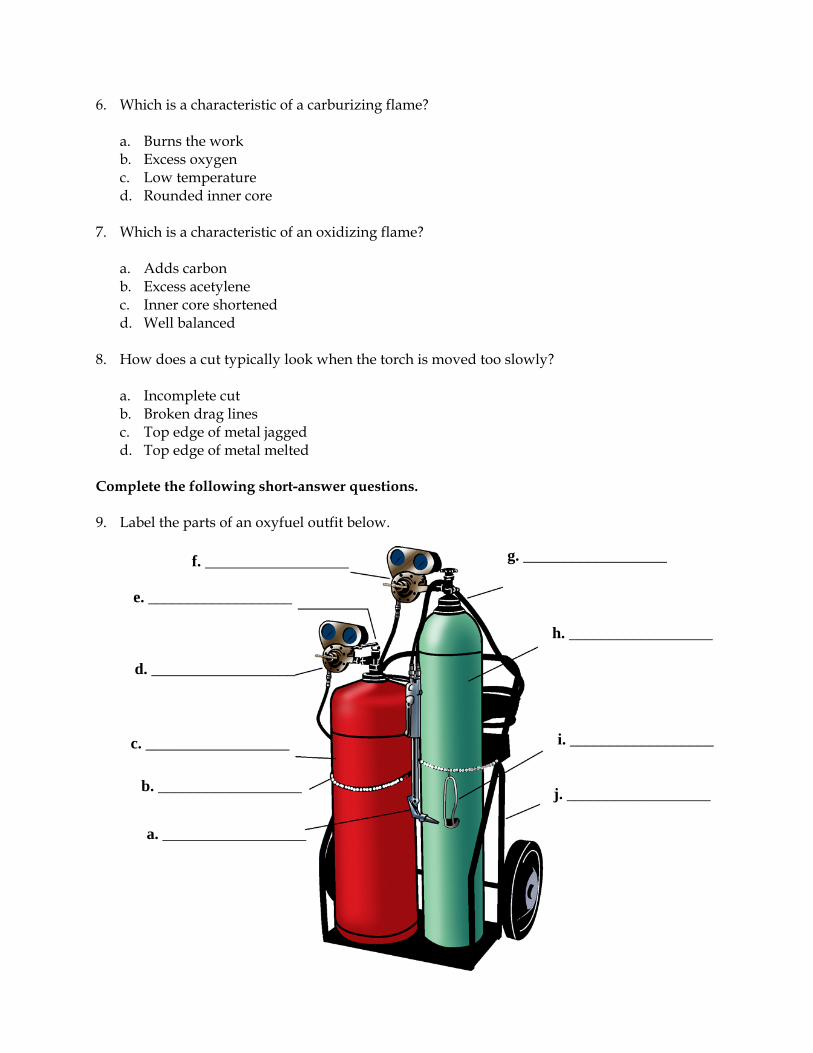
6. Which is a characteristic of a carburizing flame?
a. Burns the work b. Excess oxygen c. Low temperature d. Rounded inner core
7. Which is a characteristic of an oxidizing flame?
a. Adds carbon b. Excess acetylene c. Inner core shortened d. Well balanced
8. How does a cut typically look when the torch is moved too slowly?
a. Incomplete cut b. Broken drag lines c. Top edge of metal jagged d. Top edge of metal melted
Complete the following short-answer questions. 9. Label the parts of an oxyfuel outfit below.
a. __________________
f. __________________
c. __________________
d. __________________
e. __________________
b. __________________
g. __________________
h. __________________
i. __________________
j. __________________

10. Name four factors discussed in the lesson that can affect a cut and explain briefly why each is a factor.
a. b. c. d.
♦ Page 1 ♦
Agricultural Science I Curriculum Guide: Agricultural Mechanics Unit for Agricultural Science I Unit: VI. Oxyfuel Cutting Unit Objective:
Students will apply principles of oxyfuel cutting by making basic cuts with an oxyfuel outfit as part of a class-wide contest.
Show-Me Standards: 2.5, CA3 References:
Agricultural Mechanics Unit for Agricultural Science I. University of Missouri-Columbia, Instructional Materials Laboratory, 2002. American Welding Society. Accessed November 18, 2003, from http://www.aws.org/. Hobart Institute of Welding Technology. Accessed November 17, 2003, from http://www.welding.org/. Machinery Safety: Welding. National Ag Safety Database. Accessed November 17, 2003, from http://www.cdc.gov/nasd/menu/topic/machinery_welding.html. Missouri CDE Handbook. Accessed November 14, 2003, from http://www.dese.mo.gov/divcareered/ag_cde_guidelines.htm. Missouri FFA Agricultural Mechanics Career Development Event. Accessed November 19, 2003, from http://web.missouri.edu/~pavt0689/statecon.html. Thermadyne. Victor. Accessed November 18, 2003, from http://www.thermadyne.com/vec/index.asp?div=vec.
Instructional Strategies/Activities: • Students will engage in study questions in lessons 1 and 2. • Students will complete AS 2.1, Cutting a Straight Line Using an Oxyfuel
Outfit; AS 2.2, Cutting a Bevel Using an Oxyfuel Outfit; and AS 2.3, Cutting a Circle Using an Oxyfuel Outfit.
• Additional activities that relate to the unit objective can be found under the heading “Other Activities” in the following location: p. VI-4 (2).

Agricultural Science I
♦ Page 2 ♦
Performance-Based Assessment: Students will be divided into groups. The groups will represent teams and will participate in a contest that is similar to the oxyacetylene competency portion of the Agricultural Mechanics Career Development Event. Each student will use an oxyfuel outfit to make common cuts presented in the unit and discussed in class. Assessment will be based on the ability to safely and correctly make the assigned cuts using the oxyfuel outfit.
Agricultural Science I
♦ Page 3 ♦
Agricultural Mechanics Unit for Agricultural Science I Unit VI—Oxyfuel Cutting Instructor Guide The instructor should assign the performance-based assessment activity at the beginning of the unit. Students will work toward completing the activity as they progress through the unit lessons. The assessment activity will be due at the completion of the unit. 1. Use or adapt the activity sheets found in the unit to assess student
competency at cutting with oxyfuel. Review or supplement these activities as needed, based on student mastery of the procedures and equipment the students will be using. NOTE: Students should only complete this performance-based activity if they have mastered all the relevant competencies and have the instructor’s permission to perform the activity.
2. For the performance-based assessment activity, have students apply the skills and procedures discussed in the unit by making basic cuts with an oxyfuel outfit as part of a class-wide contest.
3. Divide the class into groups and assign students a series of cutting
procedures to perform using the oxyfuel outfit, such as making a straight cut and a 45º bevel cut and cutting out a circle. a. Each student should perform all of the assigned procedures. b. Assign students cutting procedures that they have mastered as part of the
instructional activities for this unit. 4. This activity will help prepare students for the oxyacetylene portion of the
Agricultural Mechanics Career Development Event. a. Explain or review event guidelines as needed. b. Refer to the Missouri CDE Handbook for guidelines regarding the
Agricultural Mechanics Career Development Event. The Missouri CDE Handbook is available from the Missouri Department of Elementary and Secondary Education at http://www.dese.mo.gov/divcareered/ag_cde_guidelines.htm.
5. Have students perform the assigned cutting procedures.
a. Performance in the oxyfuel competency contest will determine the student’s individual score.
b. Combine the individual scores of the group members to determine the team score for each group.
Agricultural Science I
♦ Page 4 ♦
6. The final assessment score will be based on the ability to safely and correctly make the assigned cuts using the oxyfuel outfit.
7. Present an appropriate award to the high-scoring team and individual, if
desired. 8. NOTE: The following units in this curriculum guide also include material and
competencies that are addressed by the Agricultural Mechanics Career Development Event: Unit I, Common Hand Tools; Unit IV, Tool Sharpening and Reconditioning; and Unit V, Arc Welding. Some or all of the performance-based assessment activities for these units could be combined to form a mini Agricultural Mechanics Career Development Event, if desired. To conduct a mini Agricultural Mechanics Career Development Event, maintain the same student groups for all of the performance-based assessment activities. An expanded score sheet is included at the end of each of these units that can be used to track individual and group performance in the mini CDE.
9. ADDITIONAL ACTIVITY: Create a display board using the students’ work.
Possible display board themes include the following: each student’s best work using the oxyfuel outfit, the best example of each type of procedure performed by the class, and the best work of the week.
Agricultural Science I
♦ Page 5 ♦
Agricultural Mechanics Unit for Agricultural Science I Unit VI—Oxyfuel Cutting Student Handout 1. The instructor will divide the class into groups and give you a series of
oxyfuel cutting procedures to perform as part of a class-wide contest. 2. Your group will compete in the contest as a team. 3. Perform the assigned cuts using the oxyfuel outfit.
Wear appropriate safety equipment at all times. Follow all assigned safety procedures. You can lose points for not
following safety precautions and other assigned procedures. Inspect the equipment, materials, and work area to ensure safe and correct
operation. Perform the cuts using the assigned procedure. Inspect your work. Follow shutdown and cleanup procedures and return all equipment and
materials to their assigned places. Turn in your work to the instructor.
4. Your final assessment score will be based on your ability to safely and
correctly make the assigned cuts using the oxyfuel outfit.

Agricultural Science I
♦ Page 6 ♦
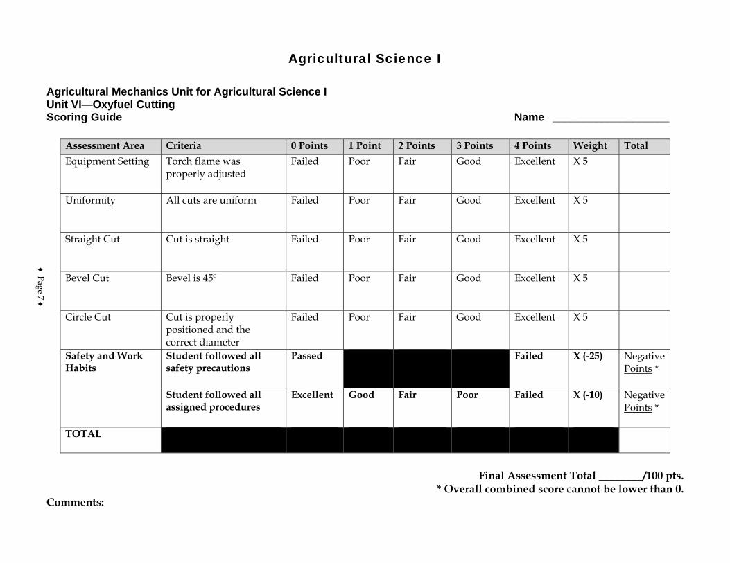
Agricultural Science I
Agricultural Mechanics Unit for Agricultural Science I Unit VI—Oxyfuel Cutting Scoring Guide Name ___________________
Assessment Area Criteria 0 Points 1 Point 2 Points 3 Points 4 Points Weight Total Equipment Setting Torch flame was
properly adjusted Failed Poor Fair Good Excellent X 5
Uniformity All cuts are uniform Failed Poor Fair Good Excellent X 5
Straight Cut Cut is straight Failed Poor Fair Good Excellent X 5
Bevel Cut Bevel is 45º Failed Poor Fair Good Excellent X 5
Circle Cut Cut is properly positioned and the correct diameter
Failed Poor Fair Good Excellent X 5
Safety and Work Habits
Student followed all safety precautions
Passed Failed X (-25) Negative Points *
Student followed all assigned procedures
Excellent Good Fair Poor Failed X (-10) Negative Points *
TOTAL
Final Assessment Total ________/100 pts.
* Overall combined score cannot be lower than 0. Comments:
♦ Page 7 ♦

♦ Page 8 ♦

♦ Page 9 ♦
Agricultural Mechanics I Score Sheet
Team Members Tool ID
Tool Sharpening/
Reconditioning Arc
Welding Oxyfuel Cutting Score
Team A Total: Team B Total: Team C Total: Team D Total: Team E Total: Team F Total:

♦ Page 10 ♦
Ag Science I – Ag Mechanics I – Painting Finishing With Paint • Page 1 of 9
Course Agricultural Science I
Unit Agricultural Mechanics I
Subunit Painting
Lesson Finishing With Paint
Estimated Time 50 minutes Student Outcome
Identify the safety procedures for painting. Demonstrate the procedures for applying paint with a paintbrush.
Learning Objectives
1. Identify the safety procedures that should be followed when painting. 2. Explain how to prepare surfaces for painting. 3. Identify some common paint failures and how can they be avoided. 4. Explain how to select brushes. 5. Explain the correct way to paint using a brush. 6. Explain how to clean and store brushes. 7. Explain how to estimate the amount of paint needed for a job.
Grade Level Expectations
Resources, Supplies & Equipment, and Supplemental Information
Resources 1. PowerPoint Slides
PPt 1 – Common Paint Failures PPt 2 – Parts of a Brush and Various Types PPt 3 – Correct Ways to Hold a Brush PPt 4 – Cleaning Brushes
2. Agricultural Mechanics Unit for Agricultural Science I (Student Reference). University of Missouri-Columbia: Instructional Materials Laboratory, 2002.
3. Curriculum Enhancement for Agricultural Mechanics Unit for Agricultural Science I, “Unit VII - Painting.” University of Missouri-Columbia: Instructional Materials Laboratory, 2004.
Supplemental Information 1. Internet Sites
Cassens, D. and W. Feist. “Paint Failure Problems and Their Cure.” Purdue University Cooperative Extension Service. Accessed September 26, 2007, from http://www.ces.purdue.edu/extmedia/NCR/NCR-133.html.
Formisano, B. Selection, Care, and Storage of a Paintbrush. About.com: Home Repair. Accessed September 26, 2007, from http://homerepair.about.com/od/interiorhomerepair/ss/paintbrush_stor.htm.
Ag Science I – Ag Mechanics I – Painting Finishing With Paint • Page 2 of 9
“A Guide to Paintbrush Selection.” Popular Mechanics, March 2003. Accessed September 26, 2007, from http://www.popularmechanics.com/home_journal/tools/1274266.html?page=1.
2. Print Burkybile, C., D. Johnson, J. Lee, and C. Shelhamer. Agricultural Power and
Technology. Danville, IL: Interstate Publishers, 2005. Phipps, L. Mechanics in Agriculture. 4th ed. Danville, IL: Interstate Publishers, 1992. Phipps, L. and G. Miller. Introduction to Agricultural Mechanics. Upper Saddle River,
NJ: Prentice Hall Interstate, 2004. 3. Electronic Media
Exterior Paint Preparation. Easy2DIY. Accessed September 26, 2007, from http://www.easy2diy.com/cm/easy/diy_ht_3d_index.asp?page_id=35749910.
Ag Science I – Ag Mechanics I – Painting Finishing With Paint • Page 3 of 9
Instructor Directions Content Outline
Objective 1
Safety procedures for painting are discussed at right.
Identify the safety procedures that should be followed when painting.
Wear appropriate protective clothing. 1. Safety glasses or goggles to protect the eyes from
splattered paints or solvents 2. Approved respirator if preparing the surface or
applying the finish produces dust or toxic fumes 3. Rubber gloves for handling bleaches, solvents, or
other caustic materials Work in a well-ventilated area. Supplement natural ventilation with forced ventilation if needed. Keep sparks and flames out of the work area. Have an approved fire extinguisher readily available. Follow safety procedures for all equipment and materials used in preparation or for painting. This includes equipment such as steam cleaners, sanders, and ladders, as well as paints and solvents. Observe safe cleanup procedures 1. Clean spills as they happen.
Interest Approach
Show different types of paint failures to the class and discuss their causes and ways to prevent them. Examples can be brought in, or students can be taken out to examine buildings and equipment in their usual settings. Has the material underneath the paint been damaged by being exposed to the elements? If so, how much work would be needed to restore it? Could the damage have been prevented or reduced by improved painting technique or by repainting sooner? How did use or environment contribute to the condition of the paint?
Communicate the Learning Objectives
1. Identify the safety procedures that should be followed when painting. 2. Explain how to prepare surfaces for painting. 3. Identify some common paint failures and how can they be avoided. 4. Explain how to select brushes. 5. Explain the correct way to paint using a brush. 6. Explain how to clean and store brushes. 7. Explain how to estimate the amount of paint needed for a job.
Ag Science I – Ag Mechanics I – Painting Finishing With Paint • Page 4 of 9
Instructor Directions Content Outline
2. Use the appropriate solvent or cleaning solution. 3. Store chemicals in approved containers and
flammable finishes and solutions in a fireproof cabinet.
4. Dispose of cleanup rags properly. 5. Wash hands after working with chemicals that are
toxic or could harm skin. Objective 2
Surfaces must be properly prepared before finishes can be applied. Discuss surface preparation of metal and wood with students.
Explain how to prepare surfaces for painting.
Metal 1. Remove surface dirt and grease with a steam cleaner,
high-pressure washer, or approved cleaning solution. Do not use gasoline.
2. Remove loose paint and rust and smooth any pitted areas by wire brushing or sanding.
3. Clean with a preparatory solvent. 4. Apply appropriate primer coat. Wood 1. Remove surface dirt and grease using approved
cleaning solutions. 2. Remove or repair surface marks and defects, such as
mill marks or dents. 3. Remove old paint using paint stripper, a wire brush,
or sandpaper. 4. Sand if smooth finish is desired. Follow by cleaning
off dust with a tack rag. 5. Apply appropriate primer coat.
Objective 3
Paint should wear down over time rather than peel, sag, or flake off. By being able to recognize common painting problems, painters can avoid making the same mistakes and better protect their buildings and equipment. Discuss common painting problems.
PPt 1 – Common Paint Failures
Identify some common paint failures and how can they be avoided.
Common paint failures 1. Alligatoring
a. Possible causes - applying a harder, less oily coat of paint over a softer, oilier one; applying a new coat before the previous coat has dried
b. Solutions - apply progressively flexible coats of paint; allow more drying time between coats
2. Cracking and scaling a. Possible causes - paint becomes hard and brittle
and cannot expand and contract with the wood; often a problem with low-quality paint, aggravated by applying paint too thickly
Ag Science I – Ag Mechanics I – Painting Finishing With Paint • Page 5 of 9
Instructor Directions Content Outline
b. Solutions - use high-quality paint; apply more thin coats instead of a single thick coat of paint
3. Blistering and peeling a. Possible causes - moisture pushes the paint off
the surface; can also be caused by heat b. Solutions - source of moisture must be removed;
repair any leaks or cracks, improve ventilation, be sure the area is completely dry before repainting; avoid heat blistering by not painting in direct sunlight
4. Running, sagging, and wrinkling a. Possible causes - applying paint too thickly b. Solution - apply more thin coats instead of a
single thick coat of paint Many paint failures are caused by cold or wet weather. Painting should be done when it is 65°F or warmer. Avoid painting in damp weather or early in the morning or late in the evening, when dew is likely to form on the work.
Objective 4
Brushes are available in a variety of sizes and for a number of different applications. Explain how to choose the correct brush for the job.
PPt 2 – Parts of a Brush and Various Types
Explain how to select brushes. 1. Bristles should have split or “flagged” ends that help
hold paint. 2. Bristles should keep an even, sharp edge when
pressed against a smooth surface and spring back when bent.
3. Brush should be well proportioned and bristles should taper smoothly from ferrule to tip.
4. Bristles should not be loose and come out. 5. Natural bristles work best with oil-based finishes,
including lacquer and shellac, but don’t work well with water-based finishes.
6. Synthetic-blend brushes are available for use with all finishes.
Objective 5
Steps for painting with a brush and caring for brushes are covered at right.
PPt 3 – Correct Ways to Hold a Brush
Explain the correct way to paint using a brush.
1. Hold the brush with the back of the handle between the thumb and first finger and with the other fingers on the ferrule.
2. Dip the brush into the finish, covering about one-third of the bristles. Touch the bristles to the inside
Ag Science I – Ag Mechanics I – Painting Finishing With Paint • Page 6 of 9
Instructor Directions Content Outline
edge of the container to remove excess finish. 3. Touch the brush to the surface and apply the finish in
light, even strokes with the brush at a slight angle to the surface.
4. Work from the highest point down. 5. Paint with the grain when painting wood. 6. Paint adjoining sections before the paint dries and
avoid repeating strokes over painted areas. This helps prevent uneven spots in the finish.
Objective 6
PPt 4 – Cleaning Brushes
Explain how to clean and store brushes.
1. Clean the brush using the appropriate solvent or cleaner.
2. Remove excess liquid by spinning the handle between your hands with the brush inside an empty container.
3. To store brushes dry, wrap the brush in heavy paper and fasten it with a rubber band or string to keep bristles in their proper shape. Store the brush flat to avoid bending bristles.
4. Brushes that are used regularly can be stored wet by suspending them in clean solvent with the bristles tightly covered. The bristles must not touch bottom, since this can damage their shape.
Objective 7 Explain how to estimate the amount of paint needed for a job.
Consult the manufacturer’s specifications to see how many square feet that a quart or gallon of the paint should cover. Remember that 4 qt = 1 gal. Determine how many square feet are in the project to be painted. Divide the number of square feet of the project by the number of square feet covered by the quart or gallon, whichever is closer to the size of the project. If the answer isn’t a whole number, round up to the next whole number. This is the amount of paint needed for one coat of paint. Keep in mind that paint is frequently cheaper by the
Ag Science I – Ag Mechanics I – Painting Finishing With Paint • Page 7 of 9
Instructor Directions Content Outline
gallon. If the job calls for more than 2 qt of paint, it may be cheaper to buy the gallon. Rough, porous, and unpainted surfaces can take more paint than smooth painted ones. It is better to have extra paint than not enough. 1. Time and money can be lost stopping to buy more
paint. 2. Custom paints can be difficult to match if more must
be purchased later. Application: Other activities
1. Have students examine the labels of finishes in the shop. What surfaces are they designed to cover? What clean-up solutions and procedures are recommended? What health and safety steps need to be followed with the finish and the clean-up solution?
2. Have a representative from a local paint store visit the class and talk about the different kinds of finishes and how to select the right one for the job.
3. Tell students that a room or wall needs painting and have them calculate the amount of paint needed to put two coats on the room or wall. (Dimensions can be supplied by the instructor, or students can be asked to make the measurements as a review of using measuring tools. The instructor should have measured the surface beforehand to verify student results.) Have them price and research paint at a paint store or on the Internet. What kind of paint and how much would they buy? What factors should they consider besides the dimensions of the surface?
4. Have students paint or refinish a project. This could be a project assembled for the agricultural mechanics course or an outside project. Outside projects should be screened by the instructor to determine that they are appropriate for the agricultural mechanics curriculum and can be finished in the time available. Students should choose appropriate primer, finish, and other painting supplies. They should demonstrate the ability to correctly and safely use the painting equipment.
Ag Science I – Ag Mechanics I – Painting Finishing With Paint • Page 8 of 9
Instructor Directions Content Outline Closure/Summary Appropriate protective clothing and good ventilation are
among the important safety considerations when painting. The first step in preparation to paint is to clean the surface of the piece that will be painted. With a good paint job, the paint wears down with time. It should not show evidence of cracking, scaling, blistering, peeling, running, sagging, or wrinkling. While natural bristles work best with oil-based finishes, they do not work well with water-based finishes. Painting strokes should be made with the grain of wood. Brushes should be cleaned with the appropriate solvent or cleaner and stored so that the bristles retain their shape. When estimating the amount of paint needed for a job, the square feet of the project should be divided by the number of square feet covered by a quart or gallon of paint.
Evaluation: Quiz Answers: 1. a 2. d 3. c 4. b 5. d 6. a 7. a 8. b 9. Students should name two of the following in each
category. Fire a. Heed warnings about flammability on finishing
products; store flammable materials in a fireproof cabinet
b. Keep the work area clear of debris and dispose of cleanup rags properly.
c. Keep equipment that can cause a spark away from finishing materials and the work area.
d. Have a fire extinguisher readily available. e. Do not smoke or allow others in the area to
smoke. Respiratory problems a. Wear an approved respirator to protect the
respiratory system from dust or toxic fumes. b. Work outside or if inside, ensure plenty of fresh
air is available.
Ag Science I – Ag Mechanics I – Painting Finishing With Paint • Page 9 of 9
Instructor Directions Content Outline
c. Supplement natural ventilation with forced ventilation if needed.
Eye and skin irritation a. Wear safety glasses or goggles to protect eyes
from splattered paints or solvents. b. Be aware of the location of an eye-washing
station in case of an accident. c. Wear rubber gloves to protect hands from contact
with finishing materials. d. Wash hands after working with chemicals that
are toxic or could harm skin. 10. a. Handle
b. Metal ferrule c. Heel d. Bristling material or trim
11. Student should list three of the following. a. Bristles with split or “flagged” ends that help
hold paint b. Bristles that keep an even, sharp edge when
pressed against a smooth surface and spring back when bent
c. Bristles that taper smoothly from ferrule to tip d. Bristles that are not loose or don't come out e. An overall shape that is well proportioned and
balances easily in the hand 12. A dry brush should be wrapped in heavy paper and
fastened with a rubber band or string to keep bristles in their proper shape. The brush should then be stored flat to avoid bending the bristles.
13. 9 ft x 16 ft = 144 sq ft x 2 walls = 288 sq ft 9 ft x 13 ft = 117 sq ft x 2 walls = 234 sq ft 288 sq ft + 234 sq ft = 522 sq ft 522/500 = 1.04 gallons 1.04 x 2 coats = 2.08 gallons The paint required is 2 gal and 1 qt.
Unit VI - Painting Name_________________________ Lesson 1: Finishing With Paint Date__________________________
Assessment Circle the letter that corresponds to the correct answer. 1. What is the last step in preparing wood and metal for painting?
a. Applying an appropriate primer coat b. Rubbing rough spots with sandpaper c. Removing old paint with a wire brush d. Cleaning the surface with an approved detergent
2. What might be done to prevent paint from alligatoring?
a. Applying more coats of paint b. Applying thicker coats of paint c. Adding moisture to the painting surface d. Allowing more drying time between coats
3. The defect in which paint becomes hard and brittle and cannot expand and contract with the
wood is called:
a. alligatoring. b. blistering. c. cracking. d. sagging.
4. The defect in which moisture or heat pushes paint off the surface is called:
a. alligatoring. b. blistering. c. cracking. d. sagging.
5. For best results, painting should be done in which environment?
a. Wet weather b. Direct sunlight c. Late in the evening d. 65ºF or warmer
6. With which type of finish do natural bristles work best?
a. Oil-based b. Water-based c. Thick d. Thin
7. What proportion of the bristles are dipped in the paint and which part of the bristles is used
to paint the surface?
a. 1/3; trim b. 1/3; heel c. 1/2; trim d. 1/2; heel
8. Which is true when considering the amount of paint to purchase?
a. A porous surface takes less paint than a smooth one. b. It is better to have a little extra paint than to run to the store for more. c. Paint is usually cheaper by the quart than the gallon. d. In calculating the amount of paint, the result should be rounded down.
Complete the following short-answer questions. 9. Name two ways to help prevent the following safety hazards from occurring in the painting
process.
Fire a. b. Respiratory problems a. b. Eye and skin irritation a. b.
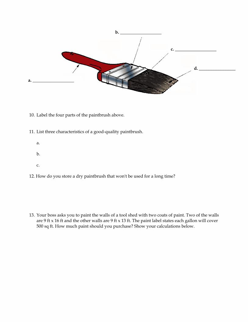
10. Label the four parts of the paintbrush above. 11. List three characteristics of a good-quality paintbrush.
a. b. c.
12. How do you store a dry paintbrush that won't be used for a long time? 13. Your boss asks you to paint the walls of a tool shed with two coats of paint. Two of the walls
are 9 ft x 16 ft and the other walls are 9 ft x 13 ft. The paint label states each gallon will cover 500 sq ft. How much paint should you purchase? Show your calculations below.
a. _________________
b. _________________
c. _________________
d. _______________
♦ Page 1 ♦
Agricultural Science I Curriculum Guide: Agricultural Mechanics Unit for Agricultural Science I Unit: VII. Painting Unit Objective:
Students will apply principles of painting by finishing a project using paint and a paintbrush.
Show-Me Standards: 2.5, CA3 References:
Agricultural Construction Volume II. University of Missouri-Columbia, Instructional Materials Laboratory, 1989. Agricultural Mechanics Unit for Agricultural Science I. University of Missouri-Columbia, Instructional Materials Laboratory, 2002. Healthy Indoor Painting Practices. U. S. Consumer Product Safety Commission. Accessed November 25, 2003, from http://www.cpsc.gov/cpscpub/pubs/456.pdf. Safe Use, Storage and Disposal of Paint. Household Hazardous Waste Project. MU Extension. University of Missouri-Columbia. Accessed November 20, 2003, from http://muextension.missouri.edu/explore/wasteman/wm6001.htm.
Instructional Strategies/Activities: • Students will engage in study questions in lesson 1. • Additional activities that relate to the unit objective can be found under
the heading “Other Activities” in the following location: p. VII-5 (1, 3, 4).
Performance-Based Assessment: Students will finish a project using paint and a paintbrush. Acceptable projects would include those made for the Agricultural Science I class or outside projects that the instructor determines are appropriate for the curriculum. Students will choose the appropriate primer, paint, and other necessary supplies. Assessment will be based on the overall quality of the work and the ability to safely and correctly complete the project within the available time.

Agricultural Science I
♦ Page 2 ♦
Agricultural Science I
♦ Page 3 ♦
Agricultural Mechanics Unit for Agricultural Science I Unit VII—Painting Instructor Guide The instructor should assign the performance-based assessment activity at the beginning of the unit. Students will work toward completing the activity as they progress through the unit lessons. The assessment activity will be due at the completion of the unit. 1. Use the lesson 1 assessment, Finishing With Paint, p. VII-9, to assess student
competency at identifying safe and correct painting procedures. Review or supplement the lesson as needed, based on student mastery of these procedures and the equipment the students will be using. NOTE: Students should only complete this performance-based activity if they have mastered all the relevant competencies and have the instructor’s permission to perform the activity.
2. For the performance-based assessment activity, have students apply the skills and procedures discussed in the unit to finish a project using paint and a paintbrush. a. Choose projects based on the skill level of the students and the time
available to work on the project. For example, if students built projects for the woodworking unit of this curriculum guide, have them paint these projects.
b. If students bring in outside projects to be painted, screen these projects to determine if they are appropriate for the curriculum and can be completed in the time available.
3. Have students choose appropriate primer, paint, and other necessary
supplies. Review and approve students’ material and equipment selection before they begin working.
4. The student handout for this activity is a Project Completion Checklist and
Project Evaluation Checklist. Students can use the checklists to track the progress of their project and evaluate their work. Supplement or modify the student handout to reflect actual projects as needed.
5. Have students turn in their completed projects. 6. The final assessment score will be based on the overall quality of the work
and the ability to safely and correctly complete the project within the available time.

Agricultural Science I
♦ Page 4 ♦
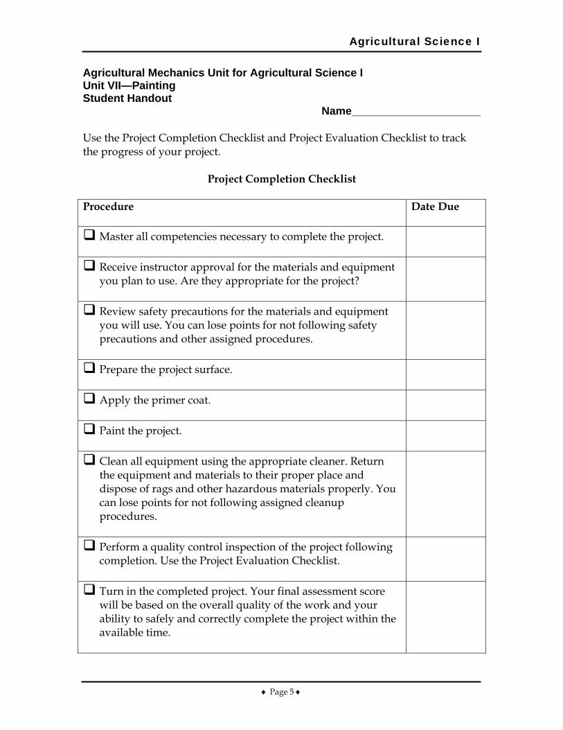
Agricultural Science I
♦ Page 5 ♦
Agricultural Mechanics Unit for Agricultural Science I Unit VII—Painting Student Handout
Name_____________________ Use the Project Completion Checklist and Project Evaluation Checklist to track the progress of your project.
Project Completion Checklist Procedure
Date Due
Master all competencies necessary to complete the project.
Receive instructor approval for the materials and equipment you plan to use. Are they appropriate for the project?
Review safety precautions for the materials and equipment you will use. You can lose points for not following safety precautions and other assigned procedures.
Prepare the project surface.
Apply the primer coat.
Paint the project.
Clean all equipment using the appropriate cleaner. Return the equipment and materials to their proper place and dispose of rags and other hazardous materials properly. You can lose points for not following assigned cleanup procedures.
Perform a quality control inspection of the project following completion. Use the Project Evaluation Checklist.
Turn in the completed project. Your final assessment score will be based on the overall quality of the work and your ability to safely and correctly complete the project within the available time.
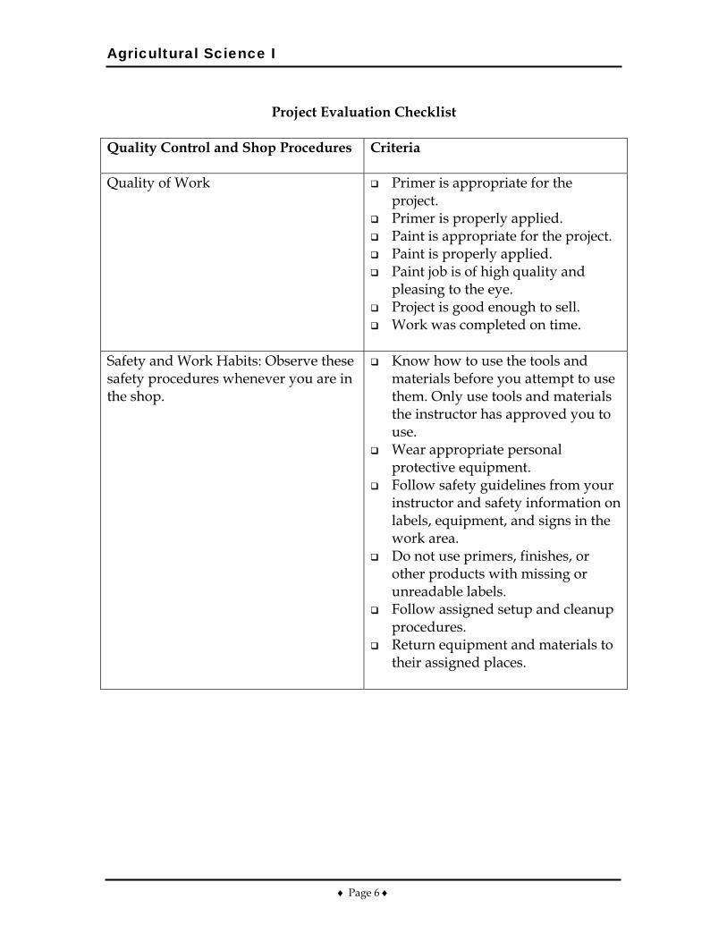
Agricultural Science I
♦ Page 6 ♦
Project Evaluation Checklist
Quality Control and Shop Procedures
Criteria
Quality of Work Primer is appropriate for the project.
Primer is properly applied. Paint is appropriate for the project. Paint is properly applied. Paint job is of high quality and
pleasing to the eye. Project is good enough to sell. Work was completed on time.
Safety and Work Habits: Observe these safety procedures whenever you are in the shop.
Know how to use the tools and materials before you attempt to use them. Only use tools and materials the instructor has approved you to use.
Wear appropriate personal protective equipment.
Follow safety guidelines from your instructor and safety information on labels, equipment, and signs in the work area.
Do not use primers, finishes, or other products with missing or unreadable labels.
Follow assigned setup and cleanup procedures.
Return equipment and materials to their assigned places.
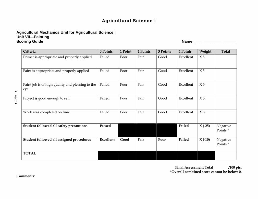
Agricultural Science I
Agricultural Mechanics Unit for Agricultural Science I Unit VII—Painting Scoring Guide Name ___________________
Criteria 0 Points 1 Point 2 Points 3 Points 4 Points Weight Total Primer is appropriate and properly applied
Failed Poor Fair Good Excellent X 5
Paint is appropriate and properly applied
Failed Poor Fair Good Excellent X 5
Paint job is of high quality and pleasing to the eye
Failed Poor Fair Good Excellent X 5
Project is good enough to sell
Failed Poor Fair Good Excellent X 5
Work was completed on time Failed Poor Fair Good Excellent X 5
Student followed all safety precautions Passed Failed X (-25) Negative Points *
Student followed all assigned procedures Excellent Good Fair Poor Failed X (-10) Negative Points *
TOTAL
Final Assessment Total ________/100 pts.
*Overall combined score cannot be below 0. Comments:
♦ Page 7 ♦

♦ Page 8 ♦