assessment of urine-diversion dehydration toilet … of urine-diversion dehydration toilet designs...
TRANSCRIPT

Assessment of Urine-Diversion Dehydration Toilet Designswith Respect to Construction Materials Used and Associated Costs
Version 1, December 2nd, 2008
by Dipl. Ing. Martin Wafler
Assessment of Urine-Diversion Dehydration
Toilet Designs with Respect to Construction
Materials Used and Associated Costs
Version 1, December 2nd, 2008
by Dipl. Ing. Martin Wafler
on behalf of German Technical Cooperation Agency (GTZ)
Assessment of Urine-Diversion Dehydration Toilet Designswith Respect to Construction Materials Used and Associated Costs
Version 1, December 2nd, 2008
by Dipl. Ing. Martin Wafler
About this brochure
Content of this brochure is the sole responsibility of the author Mr. Martin Wafler. However
helpful contributions and comments have been provided by Mr. Nanchoz Zimmermann,
seecon gmbh, and are gratefully acknowledged.
The contents reflect the personal views of the author and do not necessarily represent the
position of German Technical Cooperation Agency (GTZ).
Mentioning of any product, company/organisation, supplier, etc. in this report does not
express any preference of one or the other product, company/organisation, supplier, etc. to
another, which may not be mentioned in this report, but is of indicative purpose only.
Permission is granted for the reproduction of this information material, in whole or part, for
education, scientific or development related purposes except those involving commercial
sale.
Dipl. Ing. Martin Waflerc/o Architekten WaflerLoewengasse 47/13, 1030 Vienna, Austriaphone: +43 - (0)1 - 961 94 50mobile: +43 - (0)664 - 450 83 13fax: +43 - (0)1 - 713 06 05email: [email protected]

Assessment of Urine-Diversion Dehydration Toilet Designswith Respect to Construction Materials Used and Associated Costs
Version 1, December 2nd, 2008
by Dipl. Ing. Martin Wafler
Assessment of Urine-Diversion Dehydration Toilet Designswith Respect to Construction Materials Used and Associated Costs
Version 1, December 2nd, 2008
I
CONTENTS
CONTENTS ............................................................................................................... I
LIST OF FIGURES .................................................................................................. III
LIST OF TABLES.................................................................................................... III
ABBREVIATIONS ...................................................................................................IV
1 OBJECTIVES OF THIS BROCHURE ............................................................ 1
2 INTRODUCTION............................................................................................. 1
2.1 Urine-Diversion Dehydration Toilets vs. Composting Toilets ............................1
2.2 Urine-Diversion Dehydration Toilets.....................................................................2
2.2.1 Double-Vault Urine-Diversion Dehydration Toilets....................................................3
2.2.2 Single-Vault UDD-toilets ...........................................................................................6
3 BASIC DESIGN ASSUMPTIONS................................................................... 6
4 CHARACTARISTICS OF DIFFERENT BUILDING MATERIALS AND TECHNOLOGIES............................................................................................6
4.1 Strip foundation vs. slab foundation.....................................................................6
4.1.1 Brick masonry foundation in cement mortar..............................................................7
4.1.2 Random rubble stone masonry foundation in cement or mud mortar .......................7
4.1.3 Plain cement concrete slab foundation .....................................................................7
4.2 Country burned brick masonry vs. cement hollow block masonry, Ferro Cement and sun-dried Adobe bricks ..................................................................................7
4.2.1 Single-brick masonry in cement mortar.....................................................................7
4.2.2 Half-brick masonry in cement mortar ........................................................................8
4.2.3 Cement hollow block masonry in cement mortar ......................................................8
4.2.4 Ferro Cement............................................................................................................8
4.2.5 Sun-dried mud brick masonry in mud mortar ............................................................8
4.3 “Fixed covers” vs. “removable covers” ...............................................................9
4.4 Urine-diversion squatting pan and washbowl......................................................9
4.5 Door, jalies and ventilation system.....................................................................10
5 BRIEF DESCRIPTION OF DIFFERENT UDD-TOILET DESIGNS .............. 10
Assessment of Urine-Diversion Dehydration Toilet Designswith Respect to Construction Materials Used and Associated Costs
Version 1, December 2nd, 2008
II
5.1 Design 1 – Cement hollow block masonry atop slab foundation .....................10
5.2 Design 2 – Ferro cement arched superstructure atop cement hollow block masonry processing compartment and slab foundation ..................................12
5.3 Design 3 – Bamboo superstructure atop cement hollow block masonry and slab foundation .............................................................................................................12
5.4 Design 4 – Cement hollow block masonry atop random rubble stone masonry foundation .............................................................................................................13
5.5 Design 5 – Country burned brick masonry atop slab foundation.....................14
5.6 Design 6 – Country burned brick masonry arched superstructure atop country burned brick masonry processing compartment and slab foundation............15
5.7 Design 7 – Country burned brick masonry atop brick masonry foundation ...15
5.8 Design 8 – Adobe masonry atop country burned brick masonry processing compartment and brick masonry foundation.....................................................16
5.9 Design 9 – Adobe masonry atop random rubble stone masonry foundation .17
6 COST ESTIMATES....................................................................................... 18
7 CONCLUSION............................................................................................ 100
8 BIBLIOGRAPHY......................................................................................... 101
9 SKETCHES................................................................................................. 102
Assessment of Urine-Diversion Dehydration Toilet Designswith Respect to Construction Materials Used and Associated Costs
Version 1, December 2nd, 2008
III
LIST OF FIGURES
figure 1: Conceptual sketches of a Double-Vault UDD-toilet (left-hand side) and a Single-Vault UDD-toilet with
moveable containers (right-hand side) ...................................................................................................................... 3
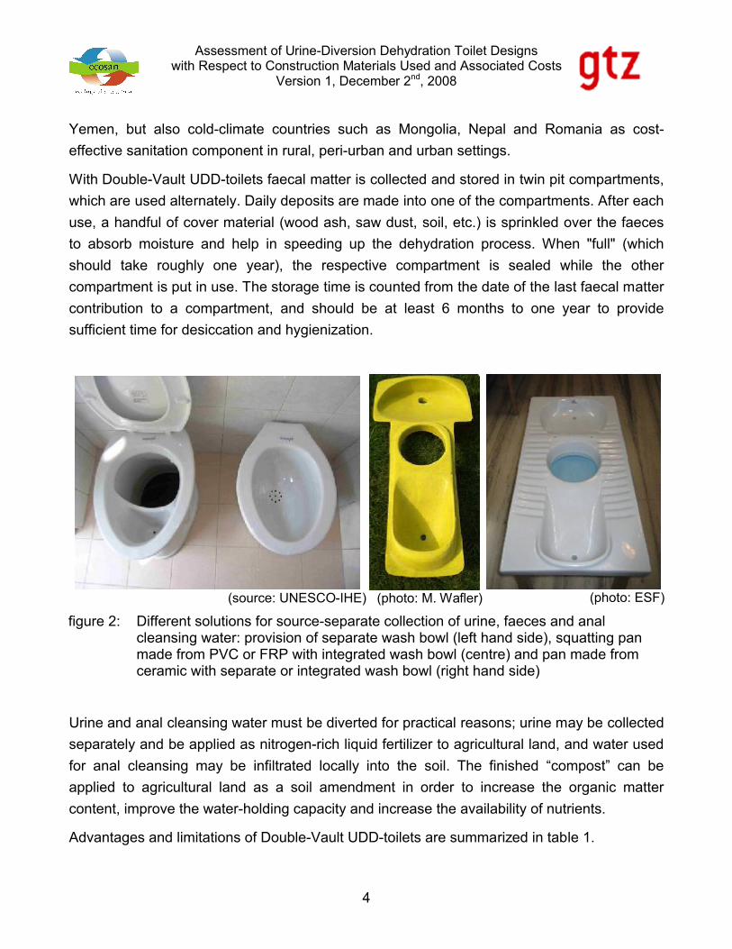
figure 2: Different solutions for source-separate collection of urine, faeces and anal cleansing water: provision of separate
wash bowl (left hand side), squatting pan made from PVC or FRP with integrated wash bowl (centre) and pan made
from ceramic with separate or integrated wash bowl (right hand side) ..................................................................... 4
figure 3: Cement hollow block (left-hand side) and cement solid block (right-hand side)............................................ 8
figure 4: Cost estimate for “Design 1” .........................................................................................................................19
figure 5: Cost estimate for “Design 2” .........................................................................................................................91
figure 6: Cost estimate for “Design 3” .........................................................................................................................92
figure 7: Cost estimate for “Design 4” .........................................................................................................................93
figure 8: Cost estimate for “Design 5” .........................................................................................................................94
figure 9: Cost estimate for “Design 6” .........................................................................................................................95
figure 10: Cost estimate for “Design 7”........................................................................................................................96
figure 11: Cost estimate for “Design 8”........................................................................................................................97
figure 12: Cost estimate for “Design 9”........................................................................................................................98
figure 13: Schematic sketch of “Design1”..................................................................................................................103
figure 14: Schematic sketch of “Design2”..................................................................................................................104
figure 15: Schematic sketch of “Design3”..................................................................................................................105
LIST OF TABLES
table 1: Advantages and limitations of Double-Vault UDD-toilets ............................................................................... 5
table 2: Advantages and limitations of Single-Vault UDD-toilets with moveable containers....................................... 5
table 3: Composition of soils that make good adobe brick ............................................................................................ 9
table 4: Summary of construction details .....................................................................................................................18
table 5: Cost comparison of “Design 1” to “Design 9”.................................................................................................99
Assessment of Urine-Diversion Dehydration Toilet Designswith Respect to Construction Materials Used and Associated Costs
Version 1, December 2nd, 2008
IV
ABBREVIATIONS
AC ........................... Asbestos Cement
BOQ ........................ Bill of Quantity
CBB ......................... Country Burned Brick
CHB......................... Cement Hollow Block
CM........................... Cement Mortar
CT............................ Composting Toilet
ESF ......................... Ecosan Services Foundation (Indian NGO)
FC............................ Ferro Cement
FRP ......................... Fibre-Reinforced Plastic
NGO ........................ Non-Governmental Organisation
PCC......................... Plain Cement Concrete
PVC ......................... Polyvinyl Chloride
RCC......................... Reinforced Cement Concrete
RRSM...................... Random Rubble Stone Masonry
SLF.......................... Slab Foundation
STF.......................... Strip Foundation
UDD......................... Urine-Diversion Dehydration
Assessment of Urine-Diversion Dehydration Toilet Designswith Respect to Construction Materials Used and Associated Costs
Version 1, December 2nd, 2008
1
1 OBJECTIVES OF THIS BROCHURE
Various organisations and individuals, amongst them Ecosan Sevices Foundation (ESF), a
Pune-based NGO (non-governmental organisation), are implementing Urine-Diversion
Dehydration (UDD) Toilets in India.
The objective of this paper is to assess different UDD-toilet designs with respect to the
construction materials used (e.g. country burned bricks, cement hollow blocks, ferro cement,
etc.) and their associated construction costs. Optimization and cost estimates are based
upon the assessment of various designs of UDD-toilets applied in India and bills of quantity
(BOQ).
2 INTRODUCTION
2.1 Urine-Diversion Dehydration Toilets vs. Composting Toilets
In India UDD-toilets are sometimes referred to as „composting toilets” (CT). This is
misleading as UDD-toilets and CTs operate in slightly different ways.
Urine-Diversion Dehydration Toilets:
UDD-toilets divert all liquids (i.e. urine and anal cleansing water, if applicable) from the faeces
to keep the processing chamber contents dry. Adding wood ash, lime, etc. after each
defecation helps in lowering moisture content and raise the pH. The system thus creates
conditions of dryness, raised pH and time for pathogen die-off [1].
Composting Toilets:
In composting toilets human faeces, or in some cases faeces plus urine (and anal cleansing
water), are deposited in a processing chamber along with organic household and garden
refuse and bulking agents (straw, peat moss, wood shavings, twigs, etc.).
A variety of organisms in the pile break down the solid into humus – just as eventually
happens to all organic materials in the natural environment. Temperature, airflow, moisture,
carbon materials and other factors are controlled to varying degrees to promote optimal
conditions for decomposition. After a certain retention time (normally 6 to 8 months) the partly
Assessment of Urine-Diversion Dehydration Toilet Designswith Respect to Construction Materials Used and Associated Costs
Version 1, December 2nd, 2008
2
decomposed material can be moved to a garden compost or an eco-station for secondary
processing through high temperature composting [1].
2.2 Urine-Diversion Dehydration Toilets
UDD-toilets make use of desiccation (dehydration) processes for the hygienically safe on-site
treatment of human excreta. Therefore, if wet anal cleansing habits should prevail in a
community, anal cleansing water must be diverted (e.g. by providing a separate washbowl)
for practical reasons (figure 2).
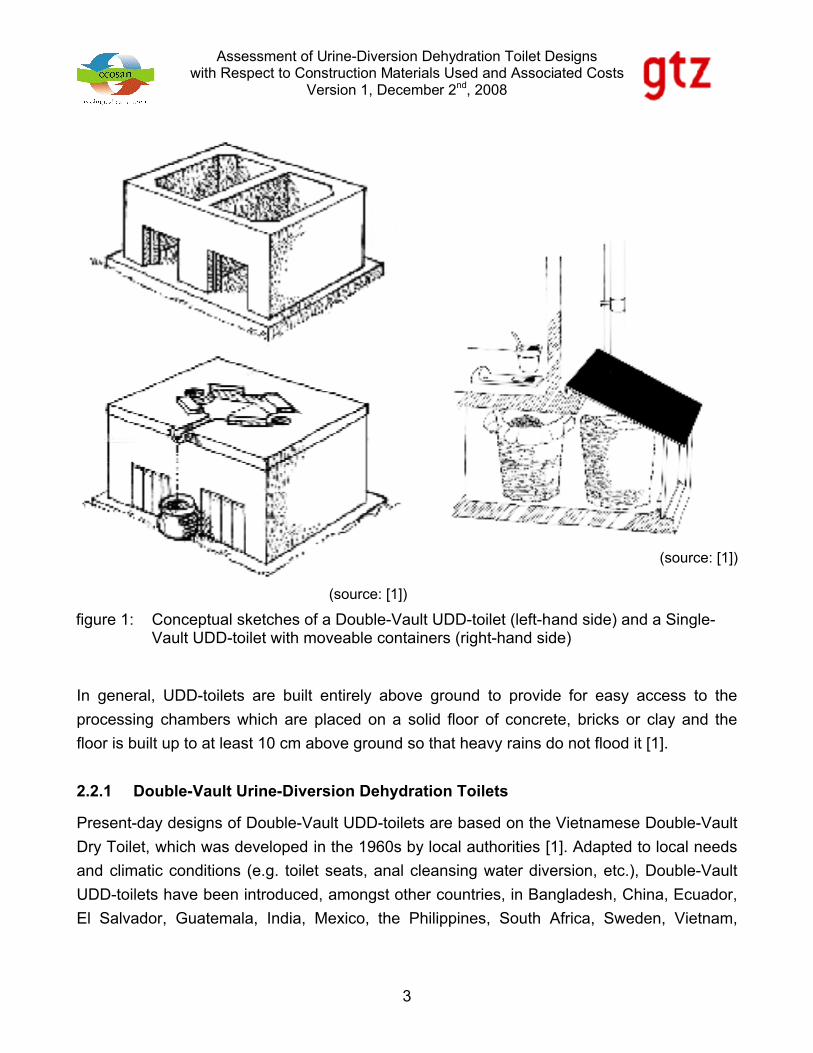
There are two distinct types of UDD-toilets viz., Double-Vault UDD-toilets (figure 1, left-hand
side) and Single-Vault UDD-toilets (figure 1, right-hand side). In order to facilitate collection of
the finished “compost” (desiccated faeces and cover material), the former ones are designed
to operate in batches whilst the latter ones provide only one collection cum storage
compartment for containment of faeces. Therefore, secondary storage or other types of
treatment (e.g. co-composting, etc.) have to be planned for.
Assessment of Urine-Diversion Dehydration Toilet Designswith Respect to Construction Materials Used and Associated Costs
Version 1, December 2nd, 2008
3
In general, UDD-toilets are built entirely above ground to provide for easy access to the
processing chambers which are placed on a solid floor of concrete, bricks or clay and the
floor is built up to at least 10 cm above ground so that heavy rains do not flood it [1].
2.2.1 Double-Vault Urine-Diversion Dehydration Toilets
Present-day designs of Double-Vault UDD-toilets are based on the Vietnamese Double-Vault
Dry Toilet, which was developed in the 1960s by local authorities [1]. Adapted to local needs
and climatic conditions (e.g. toilet seats, anal cleansing water diversion, etc.), Double-Vault
UDD-toilets have been introduced, amongst other countries, in Bangladesh, China, Ecuador,
El Salvador, Guatemala, India, Mexico, the Philippines, South Africa, Sweden, Vietnam,
(source: [1])
(source: [1])
figure 1: Conceptual sketches of a Double-Vault UDD-toilet (left-hand side) and a Single-Vault UDD-toilet with moveable containers (right-hand side)
Assessment of Urine-Diversion Dehydration Toilet Designswith Respect to Construction Materials Used and Associated Costs
Version 1, December 2nd, 2008
4
Yemen, but also cold-climate countries such as Mongolia, Nepal and Romania as cost-
effective sanitation component in rural, peri-urban and urban settings.
With Double-Vault UDD-toilets faecal matter is collected and stored in twin pit compartments,
which are used alternately. Daily deposits are made into one of the compartments. After each
use, a handful of cover material (wood ash, saw dust, soil, etc.) is sprinkled over the faeces
to absorb moisture and help in speeding up the dehydration process. When "full" (which
should take roughly one year), the respective compartment is sealed while the other
compartment is put in use. The storage time is counted from the date of the last faecal matter
contribution to a compartment, and should be at least 6 months to one year to provide
sufficient time for desiccation and hygienization.
Urine and anal cleansing water must be diverted for practical reasons; urine may be collected
separately and be applied as nitrogen-rich liquid fertilizer to agricultural land, and water used
for anal cleansing may be infiltrated locally into the soil. The finished “compost” can be
applied to agricultural land as a soil amendment in order to increase the organic matter
content, improve the water-holding capacity and increase the availability of nutrients.
Advantages and limitations of Double-Vault UDD-toilets are summarized in table 1.
(source: UNESCO-IHE) (photo: M. Wafler) (photo: ESF)
figure 2: Different solutions for source-separate collection of urine, faeces and anal cleansing water: provision of separate wash bowl (left hand side), squatting pan made from PVC or FRP with integrated wash bowl (centre) and pan made from ceramic with separate or integrated wash bowl (right hand side)
Assessment of Urine-Diversion Dehydration Toilet Designswith Respect to Construction Materials Used and Associated Costs
Version 1, December 2nd, 2008
5
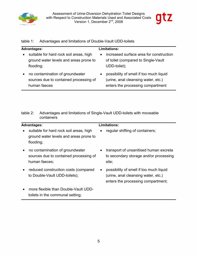
table 1: Advantages and limitations of Double-Vault UDD-toilets
Advantages: Limitations:
suitable for hard rock soil areas, high
ground water levels and areas prone to
flooding;
increased surface area for construction
of toilet (compared to Single-Vault
UDD-toilet);
no contamination of groundwater
sources due to contained processing of
human faeces
possibility of smell if too much liquid
(urine, anal cleansing water, etc.)
enters the processing compartment
table 2: Advantages and limitations of Single-Vault UDD-toilets with moveable containers
Advantages: Limitations:
suitable for hard rock soil areas, high
ground water levels and areas prone to
flooding;
regular shifting of containers;
no contamination of groundwater
sources due to contained processing of
human faeces;
transport of unsanitised human excreta
to secondary storage and/or processing
site;
reduced construction costs (compared
to Double-Vault UDD-toilets);
possibility of smell if too much liquid
(urine, anal cleansing water, etc.)
enters the processing compartment;
more flexible than Double-Vault UDD-
toilets in the communal setting;
Assessment of Urine-Diversion Dehydration Toilet Designswith Respect to Construction Materials Used and Associated Costs
Version 1, December 2nd, 2008
6
2.2.2 Single-Vault UDD-toilets
Single-Vault UDD-toilets, unlike Double-Vault UDD-toilets, provide only one collection cum
storage compartment for containment of faeces. Therefore, secondary storage or other types
of treatment (e.g. co-composting, etc.) are necessary. The most common design of Single-
Vault UDD-toilets is to provide moveable containers. Urine and anal cleansing water
diversion is equally important for Single-Vault UDD-toilets as for dehydration toilets with twin
compartments.
Advantages and limitations of Single-Vault UDD-toilets are summarized in table 2.
3 BASIC DESIGN ASSUMPTIONS
With Double-Vault UDD-toilets the required volume of each processing compartment
depends upon the anticipated number of users, specific storage capacity (i.e. volume of
faeces excreted and cover material spent per person per day) and the desired resting period.
Specific storage capacity may vary from place to place due to the different amount of faeces
excreted and kind and amount of cover material used.
The minimum clear inner dimensions (i.e. length, width, height) of a single processing
compartment are set with 1.15, 0.60 and 0.6 metres, respectively. But, depending on the
nominal size of construction materials used, actual dimensions of compartments (especially
the height) may vary.
Processing compartment volumes of ca. 400 litres provide for a storage time of at least 6
months from the date of the last faecal matter contribution to a compartment if a family of 4 to
5 heads uses the UDD-toilet on a regular basis.
4 CHARACTARISTICS OF DIFFERENT BUILDING MATERIALS AND
TECHNOLOGIES
4.1 Strip foundation vs. slab foundation
Two footing types, viz. strip foundations (STF) and slab foundations (SLF) have been
assessed. With strip foundations 2 different construction materials are considered (i.e.
country burned brick masonry and random rubble stone masonry).

Assessment of Urine-Diversion Dehydration Toilet Designswith Respect to Construction Materials Used and Associated Costs
Version 1, December 2nd, 2008
7
4.1.1 Brick masonry foundation in cement mortar
50 cm wide and 38 cm deep footing trenches have to be excavated for a 35 cm wide country
burned brick (CBB) foundation in cement mortar (CM). A trench depth of 38 cm will provide
for a 15 cm high Murum layer (at the base) and a 25 cm high brick foundation.
4.1.2 Random rubble stone masonry foundation in cement or mud mortar
Random rubble masonry is extensively used as foundation at places where stones are readily
available and an 18” (45 cm) foundation base is adequate for most soils and single or double
storey buildings [2].
40 cm wide and 50 cm deep footing trenches are excavated for a 40 cm wide random rubble
stone masonry (RRSM) foundation in cement or mud mortar.
4.1.3 Plain cement concrete slab foundation
The area to be excavated for providing a slab foundation has to exceed the projected outer
dimension of the superstructure of the toilet by 10 cm on all sides. Excavation has to be done
to a depth of 15 cm. The excavated area is filled with Murum (15 cm height) on top of which
the plain cement concrete (PCC) slab is cast in-situ. The size of the PCC slab must exceed
the projected outer dimension of the superstructure of the toilet by at least 5 cm on all sides.
The height of the PCC slab is set with 10 cm.
4.2 Country burned brick masonry vs. cement hollow block masonry,
Ferro Cement and sun-dried Adobe bricks
For construction of the processing chambers and the superstructure four main construction
materials are considered (i.e. country burned bricks, cement hollow blocks, Ferro Cement
and sun-dried Adobe bricks).
4.2.1 Single-brick masonry in cement mortar
With CBB having nominal size of ca. 230 x 110 x 70 mm (9” x 4” x 3”), single-brick masonry
walls have a nominal thickness of 230 mm.
Assessment of Urine-Diversion Dehydration Toilet Designswith Respect to Construction Materials Used and Associated Costs
Version 1, December 2nd, 2008
8
4.2.2 Half-brick masonry in cement mortar
Half-brick masonry walls have a nominal thickness of 110 mm using CBB having a nominal
size of ca. 230 x 110 x 70 mm (9” x 4” x 3”).
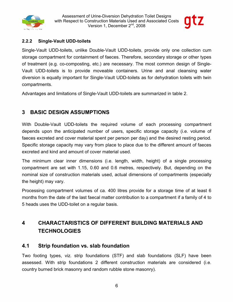
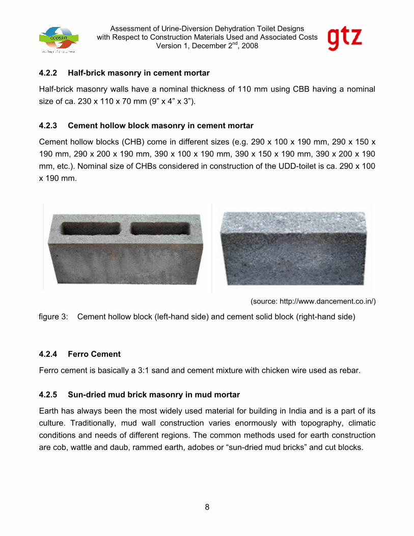
4.2.3 Cement hollow block masonry in cement mortar
Cement hollow blocks (CHB) come in different sizes (e.g. 290 x 100 x 190 mm, 290 x 150 x
190 mm, 290 x 200 x 190 mm, 390 x 100 x 190 mm, 390 x 150 x 190 mm, 390 x 200 x 190
mm, etc.). Nominal size of CHBs considered in construction of the UDD-toilet is ca. 290 x 100
x 190 mm.
4.2.4 Ferro Cement
Ferro cement is basically a 3:1 sand and cement mixture with chicken wire used as rebar.
4.2.5 Sun-dried mud brick masonry in mud mortar
Earth has always been the most widely used material for building in India and is a part of its
culture. Traditionally, mud wall construction varies enormously with topography, climatic
conditions and needs of different regions. The common methods used for earth construction
are cob, wattle and daub, rammed earth, adobes or “sun-dried mud bricks” and cut blocks.
(source: http://www.dancement.co.in/)
figure 3: Cement hollow block (left-hand side) and cement solid block (right-hand side)
Assessment of Urine-Diversion Dehydration Toilet Designswith Respect to Construction Materials Used and Associated Costs
Version 1, December 2nd, 2008
9
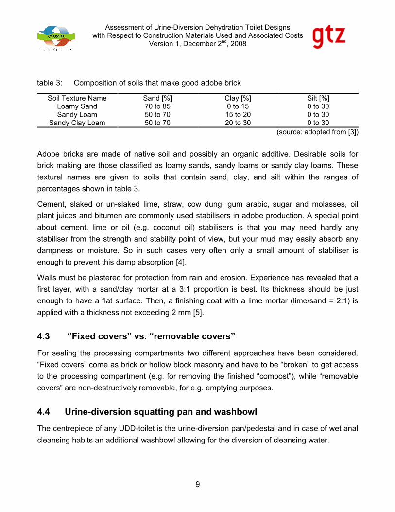
Adobe bricks are made of native soil and possibly an organic additive. Desirable soils for
brick making are those classified as loamy sands, sandy loams or sandy clay loams. These
textural names are given to soils that contain sand, clay, and silt within the ranges of
percentages shown in table 3.
Cement, slaked or un-slaked lime, straw, cow dung, gum arabic, sugar and molasses, oil
plant juices and bitumen are commonly used stabilisers in adobe production. A special point
about cement, lime or oil (e.g. coconut oil) stabilisers is that you may need hardly any
stabiliser from the strength and stability point of view, but your mud may easily absorb any
dampness or moisture. So in such cases very often only a small amount of stabiliser is
enough to prevent this damp absorption [4].
Walls must be plastered for protection from rain and erosion. Experience has revealed that a
first layer, with a sand/clay mortar at a 3:1 proportion is best. Its thickness should be just
enough to have a flat surface. Then, a finishing coat with a lime mortar (lime/sand = 2:1) is
applied with a thickness not exceeding 2 mm [5].
4.3 “Fixed covers” vs. “removable covers”
For sealing the processing compartments two different approaches have been considered.
“Fixed covers” come as brick or hollow block masonry and have to be “broken” to get access
to the processing compartment (e.g. for removing the finished “compost”), while “removable
covers” are non-destructively removable, for e.g. emptying purposes.
4.4 Urine-diversion squatting pan and washbowl
The centrepiece of any UDD-toilet is the urine-diversion pan/pedestal and in case of wet anal
cleansing habits an additional washbowl allowing for the diversion of cleansing water.
table 3: Composition of soils that make good adobe brick
Soil Texture Name Sand [%] Clay [%] Silt [%]Loamy Sand 70 to 85 0 to 15 0 to 30Sandy Loam 50 to 70 15 to 20 0 to 30
Sandy Clay Loam 50 to 70 20 to 30 0 to 30(source: adopted from [3])
Assessment of Urine-Diversion Dehydration Toilet Designswith Respect to Construction Materials Used and Associated Costs
Version 1, December 2nd, 2008
10
4.5 Door, jalies and ventilation system
Doorframes are not actually required and avoiding them considerably reduces the cost of
timber. The simplest and cost effective door can be made either of a galvanized plain steel
sheet fixed on a frame of vertical and horizontal battens or of vertical planks held together
with horizontal or diagonal battens. This can be carried by ‘holdfast’ carried into the wall [2].
Pre-cast cement concrete “windows” (so-called jalies) shall provide for light and ventilation of
the cubicle.
Each processing compartment must be equipped with a straight ventilation pipe (Ø ≥ 110
mm) that runs above the roof (at least 50 cm), is screened against flies and capped against
rain. To avoid that the roof leaks during the rainy season, the vent pipes shall not be installed
inside the cubicle but be attached to the outside wall. Like this, they do not penetrate the roof.
5 BRIEF DESCRIPTION OF DIFFERENT UDD-TOILET DESIGNS
Classification of designs is first of all based upon the main construction material (i.e. the
construction material of the processing compartments and the superstructure) and secondly
upon the kind and type of footing (e.g. PCC slab foundation, RRSM strip foundation, brick
masonry strip foundation, etc.).
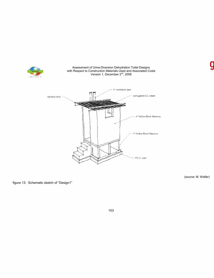
5.1 Design 1 – Cement hollow block masonry atop slab foundation
Footing:
The footing is made from a 10 cm thick PCC slab that is cast in-situ atop a 15 cm thick layer
of Murum. The top of the PCC slab shall protrude at least 10 cm above the surrounding
ground, thus preventing stagnant water from entering the processing compartments.
Processing compartments:
The processing compartments are made from 10 cm (4”) wide CHBs and provide a volume of
ca. 0.4 m3 (i.e. 400 litres) each. The clear length, width and height of each compartment are
1.15, 0.60 and 0.60 metres, respectively.
The elevated squatting platform is made from a pre-cast 7.5 cm (3”) reinforced cement
concrete (RCC) slab that is fixed atop the processing compartment walls.
Assessment of Urine-Diversion Dehydration Toilet Designswith Respect to Construction Materials Used and Associated Costs
Version 1, December 2nd, 2008
11
The openings for removal of the desiccated material are sealed with CHB masonry. The
cover has to be broken for removal of the material and redone again afterwards in order to
prevent insects and rainwater form entering the processing compartments. Mud mortar may
be used instead of cement mortar.
Neither the inner nor the outer walls of the processing compartments are plastered.
Staircase:
The steps leading to the elevated squatting platform are made from cement solid blocks
(CSB, nominal size: 290 x 100 x 190 mm) in cement mortar.
Superstructure (cubicle, door, roof, etc.):
The superstructure, which is 180 to 190 cm in height, is made from 10 cm (4”) wide CHBs.
Neither the inner nor the outer walls are plastered.
Two jalies provide for light and ventilation of the cubicle.
The door is made from a galvanized plain steel sheet (75 x 180 cm) that is fixed on a wooden
frame. The frame is made of wooden battens (50 x 25 mm) and its outer dimensions are 175
by 70 cm.
The roof is made from 2 corrugated asbestos cement (AC) sheets (105 x 150 cm, each) that
are fixed between pairs of horizontally laid bamboo sticks (about 5 cm in diameter). The lower
bamboo sticks are fixed to the superstructure with steel bar hoops (Ø 6 mm), while the upper
sticks are tied to the lower ones using ropes.
Other hardware:
A prefabricated fibre-reinforced plastic (FRP) urine-diversion squatting pan and washbowl are
installed for collection of urine in a 20 litres plastic tank and diversion of cleansing water to a
planted infiltration bed.
A wall-mounted washbasin is provided inside the toilet for proper washing hands after using
the same. The greywater from the washbasin is drained to the same infiltration bed as the
cleansing water.
Two buckets (ca. 10 litres capacity, each) are provided inside the toilet. The first is used for
storage of cover material that is sprinkled over the faeces after defecation in order to absorb
moisture and help in speeding up the dehydration process, the second for storage of water.

Assessment of Urine-Diversion Dehydration Toilet Designswith Respect to Construction Materials Used and Associated Costs
Version 1, December 2nd, 2008
12
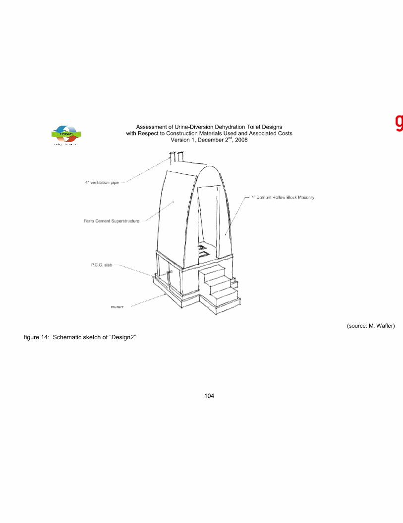
5.2 Design 2 – Ferro cement arched superstructure atop cement hollow
block masonry processing compartment and slab foundation
Footing:
Refer to chapter 5.1.
Processing compartments:
Refer to chapter 5.1.
Staircase:
Refer to chapter 5.1.
Superstructure (cubicle, door, roof, etc.):
Drawing inspiration from the so called ArchLoo (refer to [6], [7]), a V.I.P. latrine featuring a
superstructure in the shape of an inverted catenary arch (i.e. a shape that under equal load
distribution is under pure compression), a UDD-toilet superstructure made from FC and
allowing for wall thicknesses that can be as low as 25mm has been designed.
The Archloo superstructure is produced by draping (stapling) course hessian between two
catenary forms (e.g. the front and rear wall of the toilet or two wooden forms). This hessian is
then painted with a thin slurry, and then a thin layer of plaster is added. Up to 3 layers of
plaster are added, allowing drying time (4 - 7hrs) between layers. Once the outside layer has
gone off, the structure is already self supporting, and the wooden forms can be removed [6].
Otherwise, refer to chapter 5.1.
Other hardware:
Refer to chapter 5.1.
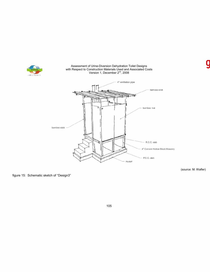
5.3 Design 3 – Bamboo superstructure atop cement hollow block
masonry and slab foundation
Footing:
Refer to chapter 5.1.
Assessment of Urine-Diversion Dehydration Toilet Designswith Respect to Construction Materials Used and Associated Costs
Version 1, December 2nd, 2008
13
Processing compartments:
Refer to chapter 5.1.
Superstructure (cubicle, door, roof, etc.):
The superstructure and the roof is made from bamboo sticks that are tied together to act as
supports for bamboo mats.
Using a plastic tarpaulin, the roof can be rendered waterproof in rainy season.
The door is made from a bamboo mat that is fixed on a wooden frame.
Other hardware:
Refer to chapter 5.1.
5.4 Design 4 – Cement hollow block masonry atop random rubble stone
masonry foundation
Footing:
The footing is made from 40 cm wide and 50 cm deep RRSM. The floors of the processing
compartments are made from 10 cm thick PCC slabs that are cast in-situ atop 15 cm thick
layers of Murum. The top of the PCC slab shall protrude at least 10 cm above the
surrounding ground, thus preventing stagnant water from entering the processing
compartments.
Processing compartments:
Due to the actual height of the CHBs (see chapter 4.2.3) the clear height of the processing
compartments is ca. 0.70 metres.
Otherwise, refer to chapter 5.1.
Staircase:
Refer to chapter 5.1.
Superstructure (cubicle, door, roof, etc.):
Refer to chapter 5.1.
Assessment of Urine-Diversion Dehydration Toilet Designswith Respect to Construction Materials Used and Associated Costs
Version 1, December 2nd, 2008
14
Other hardware:
Refer to chapter 5.1.
5.5 Design 5 – Country burned brick masonry atop slab foundation
Footing:
Refer to chapter 5.1.
Processing compartments:
The processing compartments are made from single-brick masonry (i.e. 23 cm or 9” width)
and provide a volume of ca. 0.4 m3 (i.e. 400 litres) each. The clear length, width and height of
each compartment are 1.15, 0.60 and 0.60 metres, respectively.
The openings for removal of the desiccated material are sealed with CBB masonry. The
cover has to be broken for removal of the material and redone again afterwards in order to
prevent insects and rainwater form entering the processing compartments. Mud mortar may
be used instead of cement mortar.
Both, the inner and the outer walls of the processing compartments have to be plastered
(average thickness of the plaster is set with 4 mm).
Staircase:
The steps leading to the elevated squatting platform are made from CBB in cement mortar.
Superstructure (cubicle, door, roof, etc.):
The superstructure, which is 180 to 190 cm in height, is made half-brick masonry (i.e. 11 cm
or 4” width) and the roof is made from 2 corrugated AC sheets (105 x 250 cm, each).
Otherwise, refer to chapter 5.1.
Other hardware:
Refer to chapter 5.1.
Assessment of Urine-Diversion Dehydration Toilet Designswith Respect to Construction Materials Used and Associated Costs
Version 1, December 2nd, 2008
15
5.6 Design 6 – Country burned brick masonry arched superstructure
atop country burned brick masonry processing compartment and
slab foundation
Footing:
Refer to chapter 5.1.
Processing compartments:
Refer to chapter 5.5.
Staircase:
Refer to chapter 5.5.
Superstructure (cubicle, door, roof, etc.):
Refer to chapter 5.2, but construction material is country burned bricks.
Other hardware:
Refer to chapter 5.1.
5.7 Design 7 – Country burned brick masonry atop brick masonry
foundation
Footing:
The footing is made from 35 cm wide and 38 cm deep CBB masonry. The floors of the
processing compartments are made from 10 cm thick PCC slabs that are cast in-situ atop 15
cm thick layers of Murum. The top of the PCC slab shall protrude at least 10 cm above the
surrounding ground, thus preventing stagnant water from entering the processing
compartments.
Processing compartments:
Refer to chapter 5.5.
Assessment of Urine-Diversion Dehydration Toilet Designswith Respect to Construction Materials Used and Associated Costs
Version 1, December 2nd, 2008
16
Staircase:
Refer to chapter 5.5.
Superstructure (cubicle, door, roof, etc.):
Refer to chapter 5.5.
Other hardware:
Refer to chapter 5.1.
5.8 Design 8 – Adobe masonry atop country burned brick masonry
processing compartment and brick masonry foundation
Footing:
Refer to chapter 5.7
Processing compartments:
Refer to chapter 5.7
Staircase:
Refer to chapter 5.7
Superstructure (cubicle, door, roof, etc.):
The superstructure, which is 180 to 190 cm in height, is made from adobes of ca. 330 x 150 x
100 mm (13” x 6” x 4”) nominal size. Inner and outer walls are plastered for protection from
rain and erosion. A first layer, with a sand/clay mortar at a 3:1 proportion is used to provide
for a flat surface (average thickness of the plaster is set with 6 mm). Then, a finishing coat
with a lime mortar (lime/sand = 2:1) is applied with a thickness not exceeding 2 mm (refer to
chapter 4.2.4.).
The roof is made from 2 corrugated AC sheets (105 x 250 cm, each).
Other hardware:
Refer to chapter 5.1.
Assessment of Urine-Diversion Dehydration Toilet Designswith Respect to Construction Materials Used and Associated Costs
Version 1, December 2nd, 2008
17
5.9 Design 9 – Adobe masonry atop random rubble stone masonry
foundation
Footing:
The footing is made from 40 cm wide and 50 cm deep RRSM in mud mortar. The floors of the
processing compartments are made from a 5 cm thick mud layer atop 15 cm thick layers of
Murum. The top of the mud slab shall protrude at least 10 cm above the surrounding ground,
thus preventing stagnant water from entering the processing compartments.
Processing compartments:
The processing compartments are made from adobes of 9” x 9” x 4” nominal size laid in mud
mortar and provide a volume of ca. 0.4 m3 (i.e. 400 litres) each. The clear length, width and
height of each compartment are 1.15, 0.60 and 0.60 metres, respectively.
The openings for removal of the desiccated material are sealed with mud brick masonry. The
cover has to be broken for removal of the material and redone again afterwards in order to
prevent insects and rainwater form entering the processing compartments.
Both, the inner and the outer walls of the processing compartments have to be plastered
(refer to chapter 4.2.4.).
Superstructure (cubicle, door, roof, etc.):
The elevated squatting platform is made from stouts, locally available sticks (e.g. bamboo,
etc.), laid in a crosswise manner. The sticks are then covered with mud.
The door is made from a bamboo mat fixed on a wooden frame.
Otherwise, refer to chapter 5.8.
Other hardware:
Refer to chapter 5.1.
Assessment of Urine-Diversion Dehydration Toilet Designswith Respect to Construction Materials Used and Associated Costs
Version 1, December 2nd, 2008
18
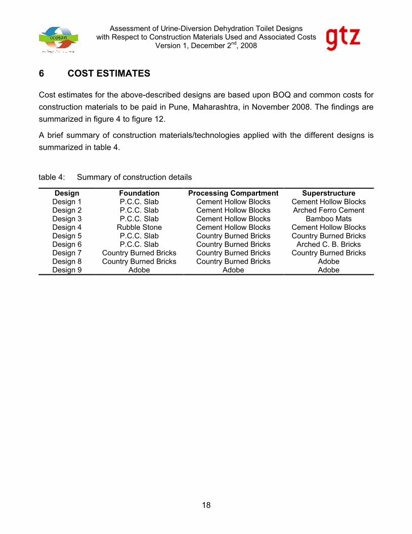
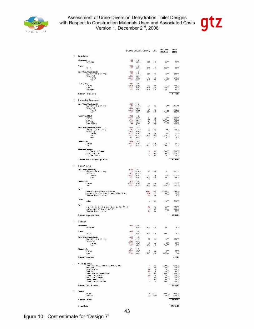
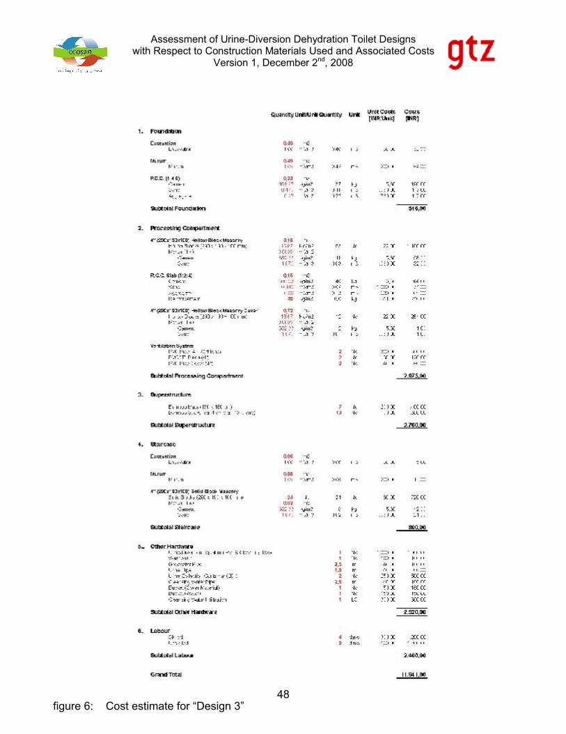
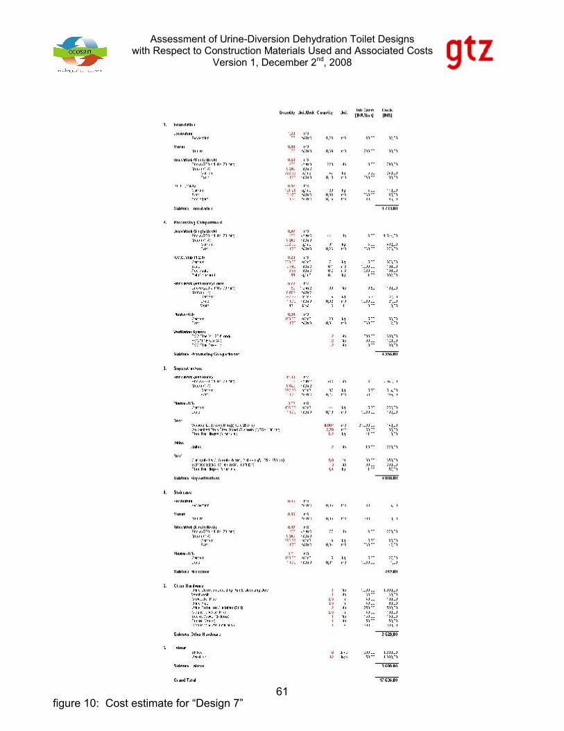
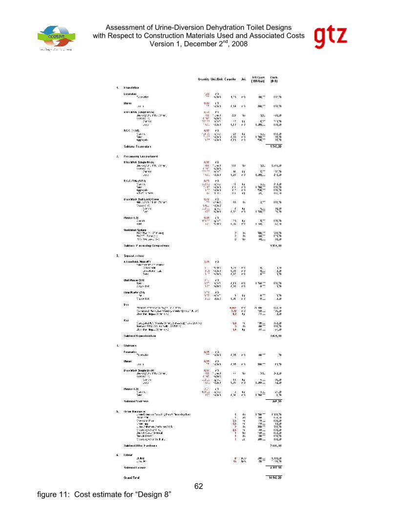
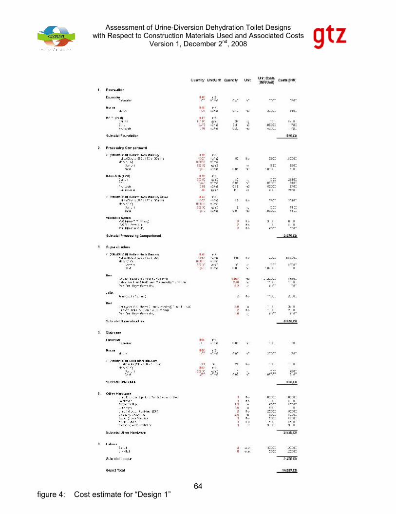
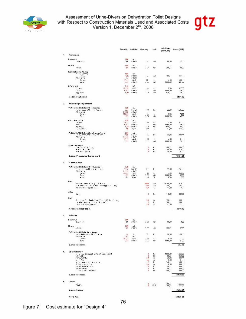
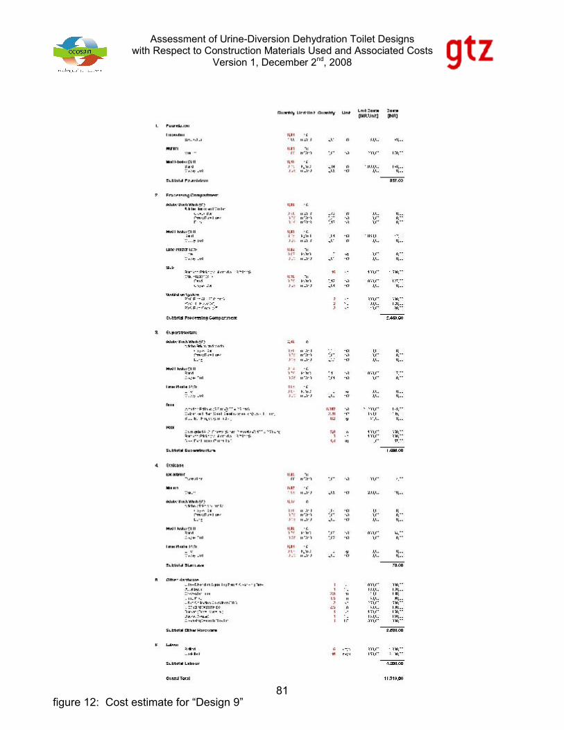
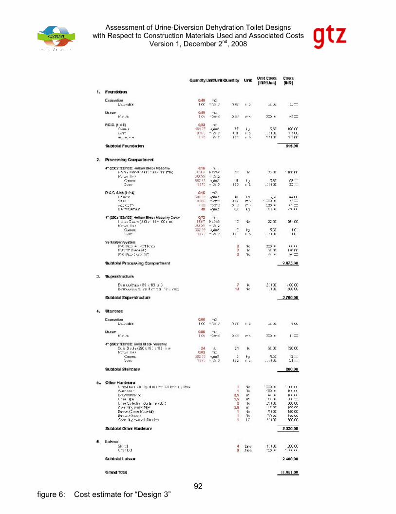
6 COST ESTIMATES
Cost estimates for the above-described designs are based upon BOQ and common costs for
construction materials to be paid in Pune, Maharashtra, in November 2008. The findings are
summarized in figure 4 to figure 12.
A brief summary of construction materials/technologies applied with the different designs is
summarized in table 4.
table 4: Summary of construction details
Design Foundation Processing Compartment SuperstructureDesign 1 P.C.C. Slab Cement Hollow Blocks Cement Hollow BlocksDesign 2 P.C.C. Slab Cement Hollow Blocks Arched Ferro CementDesign 3 P.C.C. Slab Cement Hollow Blocks Bamboo MatsDesign 4 Rubble Stone Cement Hollow Blocks Cement Hollow BlocksDesign 5 P.C.C. Slab Country Burned Bricks Country Burned BricksDesign 6 P.C.C. Slab Country Burned Bricks Arched C. B. BricksDesign 7 Country Burned Bricks Country Burned Bricks Country Burned BricksDesign 8 Country Burned Bricks Country Burned Bricks AdobeDesign 9 Adobe Adobe Adobe
Assessment of Urine-Diversion Dehydration Toilet Designswith Respect to Construction Materials Used and Associated Costs
Version 1, December 2nd, 2008
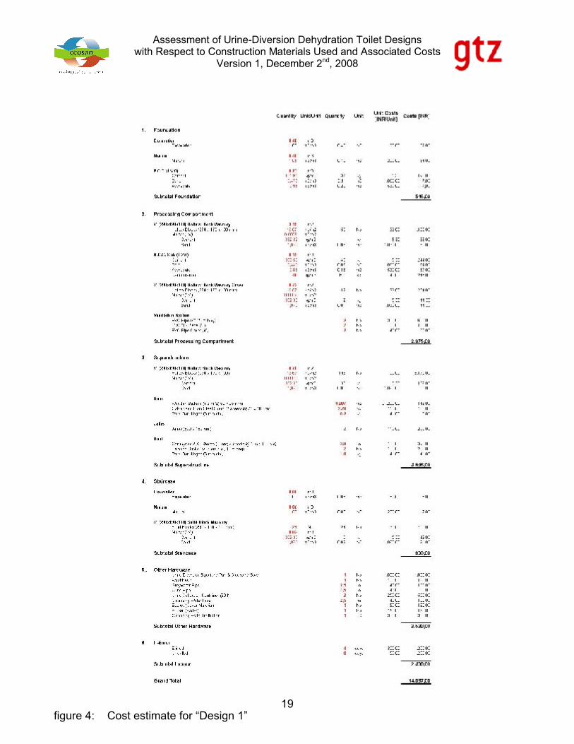
19figure 4: Cost estimate for “Design 1”
Assessment of Urine-Diversion Dehydration Toilet Designswith Respect to Construction Materials Used and Associated Costs
Version 1, December 2nd, 2008
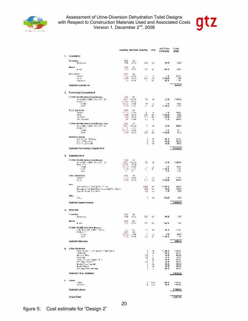
20figure 5: Cost estimate for “Design 2”

Assessment of Urine-Diversion Dehydration Toilet Designswith Respect to Construction Materials Used and Associated Costs
Version 1, December 2nd, 2008
21figure 6: Cost estimate for “Design 3”

Assessment of Urine-Diversion Dehydration Toilet Designswith Respect to Construction Materials Used and Associated Costs
Version 1, December 2nd, 2008
22figure 7: Cost estimate for “Design 4”

Assessment of Urine-Diversion Dehydration Toilet Designswith Respect to Construction Materials Used and Associated Costs
Version 1, December 2nd, 2008
23figure 8: Cost estimate for “Design 5”

Assessment of Urine-Diversion Dehydration Toilet Designswith Respect to Construction Materials Used and Associated Costs
Version 1, December 2nd, 2008
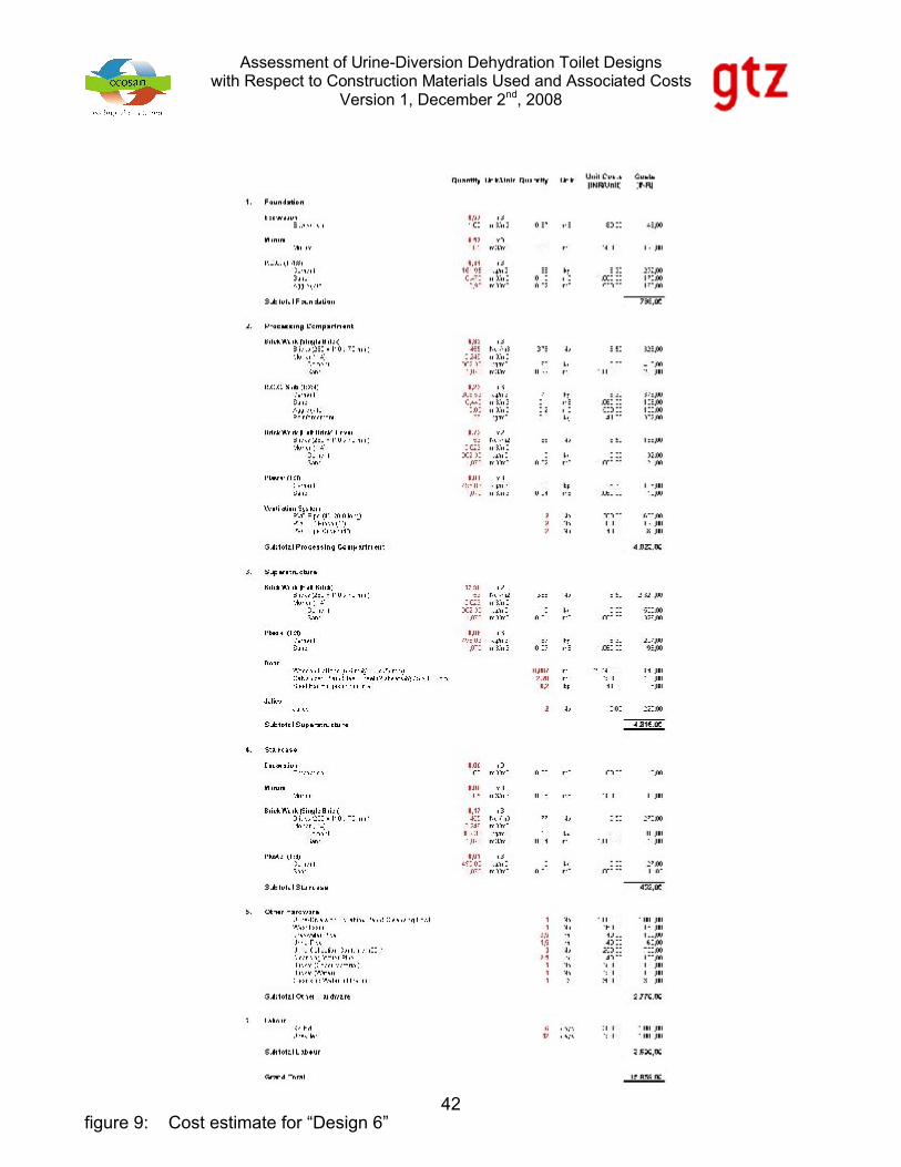
24figure 9: Cost estimate for “Design 6”

Assessment of Urine-Diversion Dehydration Toilet Designswith Respect to Construction Materials Used and Associated Costs
Version 1, December 2nd, 2008
25figure 10: Cost estimate for “Design 7”

Assessment of Urine-Diversion Dehydration Toilet Designswith Respect to Construction Materials Used and Associated Costs
Version 1, December 2nd, 2008
26figure 11: Cost estimate for “Design 8”

Assessment of Urine-Diversion Dehydration Toilet Designswith Respect to Construction Materials Used and Associated Costs
Version 1, December 2nd, 2008
27figure 12: Cost estimate for “Design 9”

Assessment of Urine-Diversion Dehydration Toilet Designswith Respect to Construction Materials Used and Associated Costs
Version 1, December 2nd, 2008
28figure 4: Cost estimate for “Design 1”

Assessment of Urine-Diversion Dehydration Toilet Designswith Respect to Construction Materials Used and Associated Costs
Version 1, December 2nd, 2008
29figure 5: Cost estimate for “Design 2”

Assessment of Urine-Diversion Dehydration Toilet Designswith Respect to Construction Materials Used and Associated Costs
Version 1, December 2nd, 2008
30figure 6: Cost estimate for “Design 3”

Assessment of Urine-Diversion Dehydration Toilet Designswith Respect to Construction Materials Used and Associated Costs
Version 1, December 2nd, 2008
31figure 7: Cost estimate for “Design 4”

Assessment of Urine-Diversion Dehydration Toilet Designswith Respect to Construction Materials Used and Associated Costs
Version 1, December 2nd, 2008
32figure 8: Cost estimate for “Design 5”

Assessment of Urine-Diversion Dehydration Toilet Designswith Respect to Construction Materials Used and Associated Costs
Version 1, December 2nd, 2008
33figure 9: Cost estimate for “Design 6”

Assessment of Urine-Diversion Dehydration Toilet Designswith Respect to Construction Materials Used and Associated Costs
Version 1, December 2nd, 2008
34figure 10: Cost estimate for “Design 7”

Assessment of Urine-Diversion Dehydration Toilet Designswith Respect to Construction Materials Used and Associated Costs
Version 1, December 2nd, 2008
35figure 11: Cost estimate for “Design 8”

Assessment of Urine-Diversion Dehydration Toilet Designswith Respect to Construction Materials Used and Associated Costs
Version 1, December 2nd, 2008
36figure 12: Cost estimate for “Design 9”

Assessment of Urine-Diversion Dehydration Toilet Designswith Respect to Construction Materials Used and Associated Costs
Version 1, December 2nd, 2008
37figure 4: Cost estimate for “Design 1”

Assessment of Urine-Diversion Dehydration Toilet Designswith Respect to Construction Materials Used and Associated Costs
Version 1, December 2nd, 2008
38figure 5: Cost estimate for “Design 2”

Assessment of Urine-Diversion Dehydration Toilet Designswith Respect to Construction Materials Used and Associated Costs
Version 1, December 2nd, 2008
39figure 6: Cost estimate for “Design 3”

Assessment of Urine-Diversion Dehydration Toilet Designswith Respect to Construction Materials Used and Associated Costs
Version 1, December 2nd, 2008
40figure 7: Cost estimate for “Design 4”

Assessment of Urine-Diversion Dehydration Toilet Designswith Respect to Construction Materials Used and Associated Costs
Version 1, December 2nd, 2008
41figure 8: Cost estimate for “Design 5”
Assessment of Urine-Diversion Dehydration Toilet Designswith Respect to Construction Materials Used and Associated Costs
Version 1, December 2nd, 2008
42figure 9: Cost estimate for “Design 6”
Assessment of Urine-Diversion Dehydration Toilet Designswith Respect to Construction Materials Used and Associated Costs
Version 1, December 2nd, 2008
43figure 10: Cost estimate for “Design 7”

Assessment of Urine-Diversion Dehydration Toilet Designswith Respect to Construction Materials Used and Associated Costs
Version 1, December 2nd, 2008
44figure 11: Cost estimate for “Design 8”

Assessment of Urine-Diversion Dehydration Toilet Designswith Respect to Construction Materials Used and Associated Costs
Version 1, December 2nd, 2008
45figure 12: Cost estimate for “Design 9”

Assessment of Urine-Diversion Dehydration Toilet Designswith Respect to Construction Materials Used and Associated Costs
Version 1, December 2nd, 2008
46figure 4: Cost estimate for “Design 1”

Assessment of Urine-Diversion Dehydration Toilet Designswith Respect to Construction Materials Used and Associated Costs
Version 1, December 2nd, 2008
47figure 5: Cost estimate for “Design 2”
Assessment of Urine-Diversion Dehydration Toilet Designswith Respect to Construction Materials Used and Associated Costs
Version 1, December 2nd, 2008
48figure 6: Cost estimate for “Design 3”

Assessment of Urine-Diversion Dehydration Toilet Designswith Respect to Construction Materials Used and Associated Costs
Version 1, December 2nd, 2008
49figure 7: Cost estimate for “Design 4”

Assessment of Urine-Diversion Dehydration Toilet Designswith Respect to Construction Materials Used and Associated Costs
Version 1, December 2nd, 2008
50figure 8: Cost estimate for “Design 5”

Assessment of Urine-Diversion Dehydration Toilet Designswith Respect to Construction Materials Used and Associated Costs
Version 1, December 2nd, 2008
51figure 9: Cost estimate for “Design 6”

Assessment of Urine-Diversion Dehydration Toilet Designswith Respect to Construction Materials Used and Associated Costs
Version 1, December 2nd, 2008
52figure 10: Cost estimate for “Design 7”

Assessment of Urine-Diversion Dehydration Toilet Designswith Respect to Construction Materials Used and Associated Costs
Version 1, December 2nd, 2008
53figure 11: Cost estimate for “Design 8”

Assessment of Urine-Diversion Dehydration Toilet Designswith Respect to Construction Materials Used and Associated Costs
Version 1, December 2nd, 2008
54figure 12: Cost estimate for “Design 9”

Assessment of Urine-Diversion Dehydration Toilet Designswith Respect to Construction Materials Used and Associated Costs
Version 1, December 2nd, 2008
55figure 4: Cost estimate for “Design 1”

Assessment of Urine-Diversion Dehydration Toilet Designswith Respect to Construction Materials Used and Associated Costs
Version 1, December 2nd, 2008
56figure 5: Cost estimate for “Design 2”

Assessment of Urine-Diversion Dehydration Toilet Designswith Respect to Construction Materials Used and Associated Costs
Version 1, December 2nd, 2008
57figure 6: Cost estimate for “Design 3”

Assessment of Urine-Diversion Dehydration Toilet Designswith Respect to Construction Materials Used and Associated Costs
Version 1, December 2nd, 2008
58figure 7: Cost estimate for “Design 4”

Assessment of Urine-Diversion Dehydration Toilet Designswith Respect to Construction Materials Used and Associated Costs
Version 1, December 2nd, 2008
59figure 8: Cost estimate for “Design 5”

Assessment of Urine-Diversion Dehydration Toilet Designswith Respect to Construction Materials Used and Associated Costs
Version 1, December 2nd, 2008
60figure 9: Cost estimate for “Design 6”
Assessment of Urine-Diversion Dehydration Toilet Designswith Respect to Construction Materials Used and Associated Costs
Version 1, December 2nd, 2008
61figure 10: Cost estimate for “Design 7”
Assessment of Urine-Diversion Dehydration Toilet Designswith Respect to Construction Materials Used and Associated Costs
Version 1, December 2nd, 2008
62figure 11: Cost estimate for “Design 8”

Assessment of Urine-Diversion Dehydration Toilet Designswith Respect to Construction Materials Used and Associated Costs
Version 1, December 2nd, 2008
63figure 12: Cost estimate for “Design 9”
Assessment of Urine-Diversion Dehydration Toilet Designswith Respect to Construction Materials Used and Associated Costs
Version 1, December 2nd, 2008
64figure 4: Cost estimate for “Design 1”

Assessment of Urine-Diversion Dehydration Toilet Designswith Respect to Construction Materials Used and Associated Costs
Version 1, December 2nd, 2008
65figure 5: Cost estimate for “Design 2”

Assessment of Urine-Diversion Dehydration Toilet Designswith Respect to Construction Materials Used and Associated Costs
Version 1, December 2nd, 2008
66figure 6: Cost estimate for “Design 3”

Assessment of Urine-Diversion Dehydration Toilet Designswith Respect to Construction Materials Used and Associated Costs
Version 1, December 2nd, 2008
67figure 7: Cost estimate for “Design 4”

Assessment of Urine-Diversion Dehydration Toilet Designswith Respect to Construction Materials Used and Associated Costs
Version 1, December 2nd, 2008
68figure 8: Cost estimate for “Design 5”

Assessment of Urine-Diversion Dehydration Toilet Designswith Respect to Construction Materials Used and Associated Costs
Version 1, December 2nd, 2008
69figure 9: Cost estimate for “Design 6”

Assessment of Urine-Diversion Dehydration Toilet Designswith Respect to Construction Materials Used and Associated Costs
Version 1, December 2nd, 2008
70figure 10: Cost estimate for “Design 7”

Assessment of Urine-Diversion Dehydration Toilet Designswith Respect to Construction Materials Used and Associated Costs
Version 1, December 2nd, 2008
71figure 11: Cost estimate for “Design 8”

Assessment of Urine-Diversion Dehydration Toilet Designswith Respect to Construction Materials Used and Associated Costs
Version 1, December 2nd, 2008
72figure 12: Cost estimate for “Design 9”

Assessment of Urine-Diversion Dehydration Toilet Designswith Respect to Construction Materials Used and Associated Costs
Version 1, December 2nd, 2008
73figure 4: Cost estimate for “Design 1”

Assessment of Urine-Diversion Dehydration Toilet Designswith Respect to Construction Materials Used and Associated Costs
Version 1, December 2nd, 2008
74figure 5: Cost estimate for “Design 2”

Assessment of Urine-Diversion Dehydration Toilet Designswith Respect to Construction Materials Used and Associated Costs
Version 1, December 2nd, 2008
75figure 6: Cost estimate for “Design 3”
Assessment of Urine-Diversion Dehydration Toilet Designswith Respect to Construction Materials Used and Associated Costs
Version 1, December 2nd, 2008
76figure 7: Cost estimate for “Design 4”

Assessment of Urine-Diversion Dehydration Toilet Designswith Respect to Construction Materials Used and Associated Costs
Version 1, December 2nd, 2008
77figure 8: Cost estimate for “Design 5”

Assessment of Urine-Diversion Dehydration Toilet Designswith Respect to Construction Materials Used and Associated Costs
Version 1, December 2nd, 2008
78figure 9: Cost estimate for “Design 6”

Assessment of Urine-Diversion Dehydration Toilet Designswith Respect to Construction Materials Used and Associated Costs
Version 1, December 2nd, 2008
79figure 10: Cost estimate for “Design 7”

Assessment of Urine-Diversion Dehydration Toilet Designswith Respect to Construction Materials Used and Associated Costs
Version 1, December 2nd, 2008
80figure 11: Cost estimate for “Design 8”
Assessment of Urine-Diversion Dehydration Toilet Designswith Respect to Construction Materials Used and Associated Costs
Version 1, December 2nd, 2008
81figure 12: Cost estimate for “Design 9”

Assessment of Urine-Diversion Dehydration Toilet Designswith Respect to Construction Materials Used and Associated Costs
Version 1, December 2nd, 2008
82figure 4: Cost estimate for “Design 1”

Assessment of Urine-Diversion Dehydration Toilet Designswith Respect to Construction Materials Used and Associated Costs
Version 1, December 2nd, 2008
83figure 5: Cost estimate for “Design 2”

Assessment of Urine-Diversion Dehydration Toilet Designswith Respect to Construction Materials Used and Associated Costs
Version 1, December 2nd, 2008
84figure 6: Cost estimate for “Design 3”

Assessment of Urine-Diversion Dehydration Toilet Designswith Respect to Construction Materials Used and Associated Costs
Version 1, December 2nd, 2008
85figure 7: Cost estimate for “Design 4”

Assessment of Urine-Diversion Dehydration Toilet Designswith Respect to Construction Materials Used and Associated Costs
Version 1, December 2nd, 2008
86figure 8: Cost estimate for “Design 5”

Assessment of Urine-Diversion Dehydration Toilet Designswith Respect to Construction Materials Used and Associated Costs
Version 1, December 2nd, 2008
87figure 9: Cost estimate for “Design 6”

Assessment of Urine-Diversion Dehydration Toilet Designswith Respect to Construction Materials Used and Associated Costs
Version 1, December 2nd, 2008
88figure 10: Cost estimate for “Design 7”

Assessment of Urine-Diversion Dehydration Toilet Designswith Respect to Construction Materials Used and Associated Costs
Version 1, December 2nd, 2008
89figure 11: Cost estimate for “Design 8”

Assessment of Urine-Diversion Dehydration Toilet Designswith Respect to Construction Materials Used and Associated Costs
Version 1, December 2nd, 2008
90figure 12: Cost estimate for “Design 9”figure 4: Cost estimate for “Design 1”

Assessment of Urine-Diversion Dehydration Toilet Designswith Respect to Construction Materials Used and Associated Costs
Version 1, December 2nd, 2008
91figure 5: Cost estimate for “Design 2”
Assessment of Urine-Diversion Dehydration Toilet Designswith Respect to Construction Materials Used and Associated Costs
Version 1, December 2nd, 2008
92figure 6: Cost estimate for “Design 3”

Assessment of Urine-Diversion Dehydration Toilet Designswith Respect to Construction Materials Used and Associated Costs
Version 1, December 2nd, 2008
93figure 7: Cost estimate for “Design 4”

Assessment of Urine-Diversion Dehydration Toilet Designswith Respect to Construction Materials Used and Associated Costs
Version 1, December 2nd, 2008
94figure 8: Cost estimate for “Design 5”

Assessment of Urine-Diversion Dehydration Toilet Designswith Respect to Construction Materials Used and Associated Costs
Version 1, December 2nd, 2008
95figure 9: Cost estimate for “Design 6”

Assessment of Urine-Diversion Dehydration Toilet Designswith Respect to Construction Materials Used and Associated Costs
Version 1, December 2nd, 2008
96figure 10: Cost estimate for “Design 7”

Assessment of Urine-Diversion Dehydration Toilet Designswith Respect to Construction Materials Used and Associated Costs
Version 1, December 2nd, 2008
97figure 11: Cost estimate for “Design 8”

Assessment of Urine-Diversion Dehydration Toilet Designswith Respect to Construction Materials Used and Associated Costs
Version 1, December 2nd, 2008
98figure 12: Cost estimate for “Design 9”

Assessment of Urine-Diversion Dehydration Toilet Designswith Respect to Construction Materials Used and Associated Costs
Version 1, December 2nd, 2008
99
table 5: Cost comparison of “Design 1” to “Design 9”
ItemDesig
n 1Desig
n 2Desig
n 3Desig
n 4Desig
n 5Desig
n 6Desig
n 7Desig
n 8Desig
n 9Footing 546,00 546,00 546,00 1.561,00 798,00 798,00 1.743,00 1.743,00 367,00Processing Compartment
2.975,00 2.975,00 2.975,00 3.424,00 4.023,00 4.023,00 4.356,00 4.356,00 2.469,00
Superstructure 4.846,00 2.686,00 2.700,00 4.846,00 4.968,00 4.316,00 4.968,00 1.674,00 1.685,00Staircase 800,00 800,00 800,00 797,00 452,00 452,00 449,00 449,00 78,00Other Hardware 2.520,0 2.520,00 2.520,00 2.520,00 2.520,00 2.520,00 2.520,00 2.520,00 2.520,00Labour 2.400,00 2.700,00 2.400,00 2.400,00 3.600,00 3.600,00 3.600,00 4.200,00 4.200,00Total 14.087,0012.227,0011.941,0015.548,0016.361,0015.959,0017.636,0014.942,0011.319,00
Assessment of Urine-Diversion Dehydration Toilet Designswith Respect to Construction Materials Used and Associated Costs
Version 1, December 2nd, 2008
100
7 CONCLUSION
With this paper it is aimed to assess different UDD-toilets designs with respect to the
construction materials used and the associated costs.
Three commonly applied building materials viz., country burned bricks, cement hollow blocks
and Ferro Cement and two alternative building materials (i.e. sun-dried mud bricks and
bamboo) have been investigated as main construction materials for UDD-toilets. But, there
are many more possible combinations of construction materials/techniques (e.g. solid blocks
made from locally available rock such as Laterite, etc.) than could be assessed. Finally, the
choice of construction material, and the actual design of the UDD-toilet, strongly depends
upon the availability or let’s better say the non-availability of certain construction materials
and the user’s preferences towards one or the other material.
From figure 4 to figure 12 and table 5 it can be seen that processing compartments made
from CHB atop a PCC slab foundation is the cheapest combination of conventional
construction materials (second to processing compartments made from adobe bricks atop a
mud floor, only). Cost for the PCC slab foundation and the CHB masonry are INR 546 and
INR 2,975, respectively.
Total costs range from ca. INR 11,300 (Design 9) to ca. INR 17,600 (Design 7).
The preferred type of sanitation facilities in many parts of India is the stand-alone toilet that is
not directly attached to the house, but is situated a bit off. But, by situating the UDD-toilet in
such a way that one or 2 walls of an existing building may be used, construction costs can be
brought down considerably.
Assessment of Urine-Diversion Dehydration Toilet Designswith Respect to Construction Materials Used and Associated Costs
Version 1, December 2nd, 2008
101
8 BIBLIOGRAPHY
[1] Winblad, U. and Simpson-Hébert, M. (2004). Ecological sanitation – revised and enlarged edition. SEI, Stockholm, Sweden.
[2] COSTFORD (2007). Cost Effective Construction Technology at COSTFORD. Available at: http://59.92.116.99/website/RDC/docsweb/Booklet-Laurie%20Baker/3-The%20Legacy/3c-Cost%20effective%20construction%20technology.pdf. Last reviewed October 11, 2008
[3] Kratzer, C. (2003). ABCs of Making Adobe Bricks. Available at: http://www.cahe.nmsu.edu/pubs/_g/G-521.pdf. Last reviewed: October 5, 2008
[4] Baker, L. (unknown). Mud. Available at: http://www.nitc.ac.in/nitc/static_files/arch/Mud-Laurie_Baker.pdf. Last revied: October 11, 2008
[5] EcoSur (2008). Building with earth: adobe, mud bricks, compressed soil. Available at: http://www.english.ecosur.org/blogcategory/Earth_construction%3A_adobe%2C_mud_bricks%2C_compressed_soil/. Last reviewed November 11, 2008
[6] Glover, P., Breslin, N. (1999). Actesiphon arch V.I.P. latrine. In: 25th WEDC Conference, Addis Ababa, Ethiopia, 1999. Available from: http://wedc.lboro.ac.uk/conferences/pdfs/25/035.pdf. Last reviewed May 6, 2008
[7] Anonymous (2006). Sanitation backlog in the Eastern Cape being alleviated. In: Civil Engineering (October 2006). Available from: http://search.sabinet.co.za/images/ejour/civeng/civeng_v14_n10_a9.pdf. Last reviewed May 6, 2008
Assessment of Urine-Diversion Dehydration Toilet Designswith Respect to Construction Materials Used and Associated Costs
Version 1, December 2nd, 2008
102
9 SKETCHES
Assessment of Urine-Diversion Dehydration Toilet Designswith Respect to Construction Materials Used and Associated Costs
Version 1, December 2nd, 2008
103
(source: M. Wafler)
figure 13: Schematic sketch of “Design1”
Assessment of Urine-Diversion Dehydration Toilet Designswith Respect to Construction Materials Used and Associated Costs
Version 1, December 2nd, 2008
104
(source: M. Wafler)
figure 14: Schematic sketch of “Design2”
Assessment of Urine-Diversion Dehydration Toilet Designswith Respect to Construction Materials Used and Associated Costs
Version 1, December 2nd, 2008
105
(source: M. Wafler)
figure 15: Schematic sketch of “Design3”
Assessment of Urine-Diversion Dehydration Toilet Designswith Respect to Construction Materials Used and Associated Costs
Version 1, December 2nd, 2008
Dipl. Ing. Martin Waflerc/o Architekten WaflerLoewengasse 47/13, 1030 Vienna, Austriaphone: +43 - (0)1 - 961 94 50
Assessment of Urine-Diversion Dehydration Toilet Designswith Respect to Construction Materials Used and Associated Costs
Version 1, December 2nd, 2008