assessment of caltrans 2070 controller in … · summarizing the caltrans approach toward...
TRANSCRIPT
ASSESSMENT OF CALTRANS 2070 CONTROLLER IN MEETING HARDWARE REQUIREMENTS OF ADVANCED TRAFFIC MANAGEMENT SYSTEMS
by
Bryant Woo
Professional MentorJack L. Kay
JHK & Associates
Prepared forCVEN 677
Advanced Surface Transportation Systems
Course InstructorConrad L. Dudek, Ph.D., P.E.
Department of Civil EngineeringTexas A&M UniversityCollege Station, Texas
August 1995

L-ii
SUMMARY
Traffic signals are a critical element in the transportation network in improving the safety andefficiency of traffic operations. The proper installation, operation, and maintenance of traffic signalscan maximize the capacity of a network, while reducing vehicle stops, travel time, and fuelconsumption. As traffic demands continue to increase, Advanced Traffic Management Systems(ATMS) are being used to better manage transportation facilities.
One element of ATMS includes advanced signal control systems, which acknowledge theeffect and interrelationship of control between adjacent traffic signals. These advanced signalcontrol systems collect data using a variety of monitoring equipment located throughout the networkand transfer that data to a central processing computer. After the central computer processes theinformation, an optimal signal timing plan for each signal is developed and then transferred to trafficsignal controllers, where the plans are implemented. If this process can occur nearly instantaneously,the signal control system would be able to respond in “real time” to varying demands in traffic.
One of the potential barriers to the successful implementation of ATMS include thecommunications and information processing limitations of existing traffic controllers. To insure thatATMS can become a reality, the California Department of Transportation (Caltrans) is developingspecifications for a new Type 2070 controller to handle the high-end applications of ATMS. Theobjectives of this paper include: 1) reviewing existing signal controllers; 2) evaluating their abilitiesin satisfying the hardware demands of current and upcoming signal control strategies; 3)summarizing the Caltrans approach toward controller design; 4) identifying the advantages anddisadvantages of that design; and 5) providing recommendations on how that design can beimproved.
The approach of this paper was to review available literature pertaining to the design andapplications of existing signal controllers. Literature pertaining to the Type 2070 controller was alsoreviewed. Signal controller manufacturers, software developers, transportation officials, andtransportation researchers were contacted to discuss the progress of the Type 2070 controllerdevelopment, as well as issues that must be considered before field implementation.
Existing signal controllers lack sufficient flexibility and computing power to accommodatethe hardware requirements of ATMS. While controller standards exist to promote interchangeabilitybetween different manufacturers, such standards do not adequately address features such as systemcoordination and communications, features that are crucial to ATMS. As a result, differentmanufacturers include proprietary features that limit interchangeability, and thus the use of controllerequipment to a variety of traffic control applications. Other controllers are designed to provideinterchangeability and flexibility, but lack the communications and information processingcapabilities to perform complex control strategies. While some controllers can be upgraded usingcustom hardware and software to perform specific applications, the absence of controllerstandardization ultimately leads to flexibility, cost, and quality control problems. To address thesedeficiencies, the Type 2070 controller features improved computing power and is designed to beflexible, while maintaining compatibility with existing controller hardware.

L-iii
While the proposed design of the Type 2070 controller is significantly improved fromexisting controller equipment, it is difficult to make an accurate assessment of its ability to satisfythe hardware requirements of ATMS. The range of ATMS requirements remain unknown and thespecifications of the Type 2070 controller are not yet finalized. As a result, the capabilities of thecontroller cannot be tested. However, measures can be taken to improve the ability in meeting futureneeds. Rather than maintaining compatibility with existing hardware, an evaluation should beperformed to determine if the Type 2070 controller can be designed with more advanced technologythat can better accommodate the demands of future traffic control systems that have not yet beenconceived. Although implementation of such a measure would be expensive, and the provision offeatures may never to fully utilized, the Type 2070 controller would more likely be able to withstandthe demand for improved hardware as technology develops.

L-iv
TABLE OF CONTENTS
INTRODUCTION . . . . . . . . . . . . . . . . . . . . . . . . . . . . . . . . . . . . . . . . . . . . . . . . . . . . . . . . . L-1Objectives . . . . . . . . . . . . . . . . . . . . . . . . . . . . . . . . . . . . . . . . . . . . . . . . . . . . . . . . . . L-1Scope . . . . . . . . . . . . . . . . . . . . . . . . . . . . . . . . . . . . . . . . . . . . . . . . . . . . . . . . . . . . . . L-1Study Approach . . . . . . . . . . . . . . . . . . . . . . . . . . . . . . . . . . . . . . . . . . . . . . . . . . . . . L-2Organization of Report . . . . . . . . . . . . . . . . . . . . . . . . . . . . . . . . . . . . . . . . . . . . . . . L-2
EXISTING TRAFFIC SIGNAL CONTROLLER TECHNOLOGY . . . . . . . . . . . . . . . . L-3Pretimed Controllers . . . . . . . . . . . . . . . . . . . . . . . . . . . . . . . . . . . . . . . . . . . . . . . . . L-3
Electromechanical Controllers . . . . . . . . . . . . . . . . . . . . . . . . . . . . . . . . . . . . L-3Solid-State Controllers . . . . . . . . . . . . . . . . . . . . . . . . . . . . . . . . . . . . . . . . . . L-3
Actuated Controllers . . . . . . . . . . . . . . . . . . . . . . . . . . . . . . . . . . . . . . . . . . . . . . . . . L-5NEMA Controller . . . . . . . . . . . . . . . . . . . . . . . . . . . . . . . . . . . . . . . . . . . . . . . L-5Type 170 Controller . . . . . . . . . . . . . . . . . . . . . . . . . . . . . . . . . . . . . . . . . . . . . L-5
NETWORK CONTROL STRATEGIES . . . . . . . . . . . . . . . . . . . . . . . . . . . . . . . . . . . . . . L-7Signal Coordination . . . . . . . . . . . . . . . . . . . . . . . . . . . . . . . . . . . . . . . . . . . . . . . . . . L-7
Time-Based Coordination . . . . . . . . . . . . . . . . . . . . . . . . . . . . . . . . . . . . . . . . L-9Direct Interconnection . . . . . . . . . . . . . . . . . . . . . . . . . . . . . . . . . . . . . . . . . . . L-9
Advanced Signal Control Systems . . . . . . . . . . . . . . . . . . . . . . . . . . . . . . . . . . . . . . L-9Central Control Systems . . . . . . . . . . . . . . . . . . . . . . . . . . . . . . . . . . . . . . . . . L-9Arterial Control Systems . . . . . . . . . . . . . . . . . . . . . . . . . . . . . . . . . . . . . . . . . L-10Integrated Control Systems . . . . . . . . . . . . . . . . . . . . . . . . . . . . . . . . . . . . . . . L-10
Advanced Signal Control Strategies . . . . . . . . . . . . . . . . . . . . . . . . . . . . . . . . . . . . . L-10“First Generation” Strategies . . . . . . . . . . . . . . . . . . . . . . . . . . . . . . . . . . . . . L-10“1.5 Generation” Strategies . . . . . . . . . . . . . . . . . . . . . . . . . . . . . . . . . . . . . . L-11On-Line Strategies . . . . . . . . . . . . . . . . . . . . . . . . . . . . . . . . . . . . . . . . . . . . . . L-11
EXISTING HARDWARE EVALUATION . . . . . . . . . . . . . . . . . . . . . . . . . . . . . . . . . . . . . L-13Accommodating Advanced Control Systems . . . . . . . . . . . . . . . . . . . . . . . . . . . . . L-13
Advantages/Disadvantages of Pretimed Controllers . . . . . . . . . . . . . . . . . . . . L-13Advantages/Disadvantages of NEMA Controllers . . . . . . . . . . . . . . . . . . . . . . L-14Advantages/Disadvantages of Type 170 Controllers . . . . . . . . . . . . . . . . . . . . L-15
Accommodating ATMS . . . . . . . . . . . . . . . . . . . . . . . . . . . . . . . . . . . . . . . . . . . . . . . L-16
CALTRANS TYPE 2070 CONTROLLER . . . . . . . . . . . . . . . . . . . . . . . . . . . . . . . . . . . . . L-18System Architecture . . . . . . . . . . . . . . . . . . . . . . . . . . . . . . . . . . . . . . . . . . . . . . . . . . L-18
Central Processing Unit (CPU) . . . . . . . . . . . . . . . . . . . . . . . . . . . . . . . . . . . . L-18Field I/O Module . . . . . . . . . . . . . . . . . . . . . . . . . . . . . . . . . . . . . . . . . . . . . . . L-22System Communications Module . . . . . . . . . . . . . . . . . . . . . . . . . . . . . . . . . . . L-22Front Panel Module . . . . . . . . . . . . . . . . . . . . . . . . . . . . . . . . . . . . . . . . . . . . . L-22Power Supply Module . . . . . . . . . . . . . . . . . . . . . . . . . . . . . . . . . . . . . . . . . . . L-22Chassis and Backplane . . . . . . . . . . . . . . . . . . . . . . . . . . . . . . . . . . . . . . . . . . L-24

L-v
Advantages of Type 2070 Controller . . . . . . . . . . . . . . . . . . . . . . . . . . . . . . . . . . . . L-24VMEbus . . . . . . . . . . . . . . . . . . . . . . . . . . . . . . . . . . . . . . . . . . . . . . . . . . . . . . L-24Compliance With Industry Standards . . . . . . . . . . . . . . . . . . . . . . . . . . . . . . . L-27Software Development Tools . . . . . . . . . . . . . . . . . . . . . . . . . . . . . . . . . . . . . . L-27User Friendliness . . . . . . . . . . . . . . . . . . . . . . . . . . . . . . . . . . . . . . . . . . . . . . . L-27
Disadvantages of Type 2070 Controller . . . . . . . . . . . . . . . . . . . . . . . . . . . . . . . . . . L-27Hardware and Software Costs . . . . . . . . . . . . . . . . . . . . . . . . . . . . . . . . . . . . . L-28Cost-Effectiveness . . . . . . . . . . . . . . . . . . . . . . . . . . . . . . . . . . . . . . . . . . . . . . L-28User Familiarity . . . . . . . . . . . . . . . . . . . . . . . . . . . . . . . . . . . . . . . . . . . . . . . . L-28
CONCLUSION . . . . . . . . . . . . . . . . . . . . . . . . . . . . . . . . . . . . . . . . . . . . . . . . . . . . . . . . . . . L-29
RECOMMENDATIONS . . . . . . . . . . . . . . . . . . . . . . . . . . . . . . . . . . . . . . . . . . . . . . . . . . . . L-30
ACKNOWLEDGMENTS . . . . . . . . . . . . . . . . . . . . . . . . . . . . . . . . . . . . . . . . . . . . . . . . . . . L-31
REFERENCES . . . . . . . . . . . . . . . . . . . . . . . . . . . . . . . . . . . . . . . . . . . . . . . . . . . . . . . . . . . . L-32
APPENDIX A . . . . . . . . . . . . . . . . . . . . . . . . . . . . . . . . . . . . . . . . . . . . . . . . . . . . . . . . . . . . . L-35

L-1
INTRODUCTION
Since their installation in Cleveland, Ohio in 1914 (1), traffic signals have become a criticalelement in improving the safety and efficiency of operations on the transportation network. Theproper design, installation, operation, and maintenance of traffic signals can maximize systemcapacity while reducing vehicle stops, travel time, and fuel consumption. Traffic signals are alsoused to orderly control potentially conflicting and hazardous pedestrian and vehicular movements.As a result, traffic signals have been utilized in a variety of applications to coordinate and managetransportation systems.
However, current trends of increasing automobile ownership and usage will undoubtedlyplace heavy demands on transportation engineers and planners to maintain high levels of mobility.To accomplish this task, the transportation community is relying on Advanced Traffic ManagementSystems (ATMS). ATMS utilize state-of-the-art computer technology and the latest innovations inelectronics and communications to: 1) collect real-time traffic data; 2) manage that data; 3) developtraffic control plans in response to current conditions; and 4) communicate those plans to controlpoints within the transportation network.
For the successful implementation of ATMS, the design of traffic signal controllers must beable to integrate new and upcoming technologies with existing hardware at minimal cost and labor.The ability of traffic signal controllers to accommodate advances in technology could yield furtherimprovements to traffic operations.
Objectives
This paper provides an evaluation of the ability of current traffic signal controllers inintegrating new technologies to existing hardware. The objectives of this paper are to:
1. review the design of existing traffic signal controllers;2. identify deficiencies of existing controllers in accommodating current and upcoming
technologies; 3. discuss the current approach in the design of a next generation of controllers;4. identify the advantages and disadvantages of the new design; and5. provide recommendations on how that design can be improved to accommodate a
broad range of applications.
Scope
While different manufacturers are featuring a variety of advanced traffic controllers (ATCs)with similar designs, the scope of this paper is limited to the design of an ATC as defined by theCaltrans Transportation Electrical Equipment Specifications for the Model 2070 ATMS ControllerUnit of October 1994 (2). This paper is intended to provide an evaluation of existing trafficcontrollers and the Type 2070 controller design. The content of this paper is based on a review ofavailable literature and disucssions with transportation professionals.
L-2
Study Approach
A state-of-the-art literature review was conducted in order to establish backgroundinformation on existing traffic controllers, traffic control strategies, upcoming ATMS applications,Type 2070 controller architecture, computer open architecture standards, and computer operatingsystems. The progress of development of the Type 2070 controller was revealed by contacting signalcontroller manufacturers, software developers, consultant firms, transportation researchers, andofficials from transportation agencies. Through the contacts, a variety of issues regardingimplementation of the Type 2070 controller were also revealed.
Organization of Report
The report is divided into five sections. The first section of the report summarizes the typesof traffic signal controllers currently in use. The second section reviews the different networkcontrol strategies that are used to optimize the efficiency of the transportation network as a completesystem. The third section evaluates the ability of existing controllers to accommodate the hardwarerequirements of existing network control systems. The purpose of this section is to identify thestrengths and weaknesses of existing hardware in light of ATMS requirements and demonstrate theneed for developing the Type 2070 controller. The fourth section of the report outlines thearchitecture of the Type 2070 controller and summarizes the advantages of disadvantages of itsdesign. The final section provides a discussion of the range of ATMS applications, conclusions, andrecommendations for an improved design.

L-3
EXISTING TRAFFIC SIGNAL CONTROLLER TECHNOLOGY
A traffic signal controller is an electrical mechanism mounted in a cabinet that establishesthe signal timing plan, the sequence and durations that green, yellow, and red indications aredisplayed for various phases. Each phase controls a set of traffic movements. Two types ofcontrollers are currently in use: pretimed and actuated.
Pretimed Controllers
With pretimed controllers, signal timing plans are predetermined using either simple manualstrategies or computer optimization programs. Based on historical data, a set of off-line signaltiming plans are developed for AM, Midday, PM, and off-peak hours. The manner which signaltiming plans are implemented vary depending on the type of pretimed controller, electromechanicalor solid-state.
Electromechanical Controllers
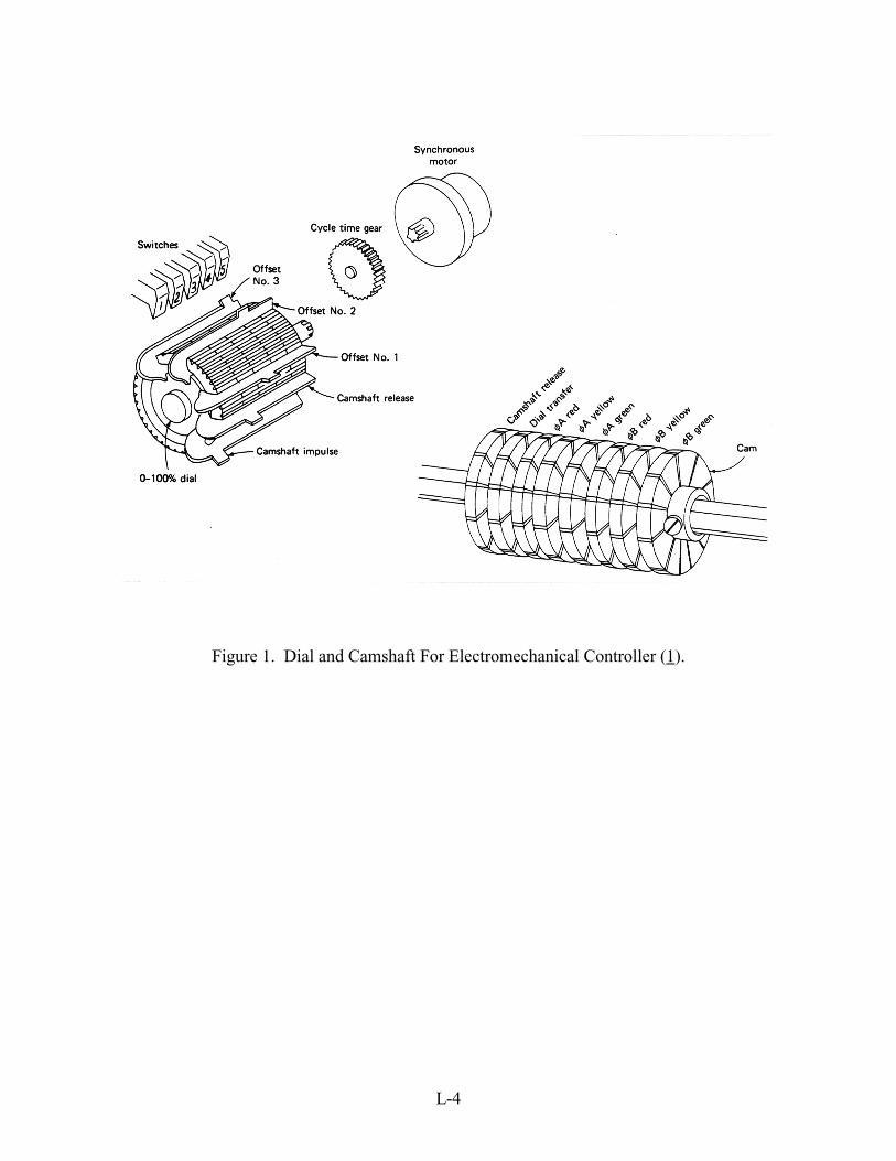
Electromechanical controllers were the first commercially available units for traffic controland remain in use in many U.S. cities (1). As shown in Figure 1, this type of controller is comprisedof a dial driven by synchronous motors and a camshaft. The motor drives a dial through a set ofgears. The size of the gear determines the cycle length (the amount of time to complete onecomplete sequence of phases). One complete revolution of the dial produces one cycle. The numberof dials (one, two, or three) controls the number of different cycle lengths available. Keys fit intothe dial and at the preset point cause a set of contacts to close and advance the camshaft. Separatecams on the camshaft control the displays (green, yellow, red, WALK, etc.) for a particular phase.
Solid-State Controllers
Solid-state pretimed controllers perform the same function as an electromechanicalcontroller, but solid-state parts replace the synchronous motors, dials, keys, and camshafts (1). Thesignal timing plan is stored in random access memory (RAM) and can be changed via keyboardentry, thumbwheel switches, program pins, or dual-in-place switches. The software and data forperforming controller operations are “burned onto” chips representing programmable read-onlymemory (PROM). A microprocessor processes the software and sends commands that control signaloperations.
To ensure that a microprocessor-based controller is functioning properly, additional auxiliaryequipment is required. Conflict monitors determine if the controller attempts to allocate right of wayto conflicting movements. Other equipment or software adjustments are required to perform specialfunctions (discussed in later sections).
L-4
Figure 1. Dial and Camshaft For Electromechanical Controller (1).

L-5
Actuated Controllers
The inherent weakness of pretimed controllers is its inability to vary a signal timing plan inresponse to varying levels of demand. An actuated controller is a solid-state, microprocessor-basedcontroller that operates with variable vehicular and pedestrian timing and phasing intervals that aredependent on current traffic and pedestrian volumes. Vehicle demands are determined frominformation obtained by detectors installed in the pavement while pedestrians are detected with pushbuttons. There are currently two types of actuated controllers, one that is based on NationalElectrical Manufacturers Association (NEMA) standards, or the other on Type 170 standards.
NEMA Controller
Manufacturers of controller equipment have voluntarily agreed to conform hardware tostandard mechanical and electrical connectors as specified by the NEMA TS1 standard (3). Forexample, the standard sets physical and functional specifications for input/output connections (seeAppendix A). In spirit, the purpose of this standard is to provide interchangeability betweencontrollers of different manufacturers that conform to the NEMA standard.
Type 170 Controller
The Type 170 standard was jointly developed by the California Department of Transportation(Caltrans) and the New York State Department of Transportation (NYSDOT) to set specificationsfor a uniform traffic control microcomputer. The Type 170 standard, like the NEMA TS1 standard,sets specifications for electrical connectors. However, the standard also sets specifications for thetype of microprocessor, memory requirements, and read only memory (ROM) sizes (4). In addition,portable software standards are set through a specified program module--an insertable card withROM that stores the traffic control program. This module could be inserted into any other Type 170controller without modification.
Caltrans uses the Type 170 exclusively as its standard traffic controller. These units functionas stored program, digital microcomputers to provide programmed logic for traffic control. Eachunit is composed of a case and plug-in printed circuit board modules as shown in Figure 2. Basicmodules include memory, central processing unit (CPU), input-output (I/O), panel control, PROM,modem, and power supply. The performance of the microcomputer is dependent on the selectionof hardware and software. A modernization of the Type 170, called the Type 179, has beenundertaken by NYSDOT (5). Although similar to the Type 170, the Type 179 features morecomputing power and a real-time operating system (4).

L-6
Figure 2. Type 170 Controller Unit Block Diagram (5).

L-7
NETWORK CONTROL STRATEGIES
The previous section reviewed the basic traffic signal controller hardware and the possibletraffic control strategies for “isolated” signals. An “isolated” signal is one whose signal timing planis independent of adjacent signals in the vicinity. This section reviews different control strategiesthat optimize the efficiency of the transportation network as a complete system.
Signal Coordination
A “coordinated” signal is one whose signal timing plan is designed to help optimize theefficiency of the transportation network by accounting for the timing of other signals. To assist inthe development of optimized timing plans in coordinated systems, many agencies rely oncomputerized models, which are based either on progression-based or performance-index-basedtechniques.
Progression-based techniques maximize the “bandwidth” along an arterial (the amount ofgreen time available for the continuous movement of vehicles). Such techniques are mostappropriate for isolated arterials because they favor movement along an arterial at the expense ofcross-street traffic, which could produce adverse effects at adjacent locations of the network. Twotime-space diagrams, shown in Figure 3, describe the application of progression-based techniquesalong an arterial. The first diagram demonstrates a signal timing plan that treats both directionsalong the arterial equally, while the second describes a plan that favors only one direction (as mightbe done on an arterial with a predominant directional flow) (6). Because the application ofprogression-based techniques become more difficult as the complexity of traffic patterns and signaltiming plans increase, many engineers use models such as PASSER and MAXBAND. These modelsdetermine the optimal cycle length, phase sequence, splits, and offsets at each intersection along thearterial to maximize the sum of the bandwidths in both directions (7). In addition, PASSERestimates measures of effectiveness (such as volume-to-capacity ratio, delays, stops, and fuelconsumption) to evaluate each timing plan.
Performance-index-based techniques generate signal timing plans that minimize theperformance index (PI) of operations, a weighted average of delays, stops, or fuel consumption inthe transportation network (7). The TRANSYT model, which can be used for optimizing a singlearterial, intersecting arterials, or a variety of network configurations, is an example of this approach.Using information on traffic volumes, system geometries, travel speeds, and signal timing data, themodel simulates traffic flow on the system and estimates travel times, delays, number of stops,volume-to-capacity ratios, fuel consumption, and queue lengths. The model then optimizes the PIby selecting appropriate cycle lengths, splits, and offsets for the signal system. Some of theweaknesses of the TRANSYT model include its inability to optimize phase sequences, or modelinteractions between different signal subsystems.

L-8

L-9
To implement the signal timing plans generated by computerized models, traffic signals canbe coordinated using either time-based coordination or direct interconnection.
Time-Based Coordination
Time-based signal coordination is performed by using synchronized clocks, which may eitherbe external units, or part of a Type 170 or NEMA controller. A library of signal timing plansgenerated off-line using historical data is input to the controller and each plan is designed to operateat a particular time of day. The use of synchronized clocks assures that coordinated signal timingplans will be implemented at all controllers simultaneously.
Some of the problems associated with time-based coordination include hardware limitations.Controller equipment may be incompatible, or the existing controller cabinets may be too small. Itis often less expensive to replace the controllers with new units that have time-based coordinationcapabilities, rather than upgrading existing hardware. Another problem with time-basedcoordination is the absence of physical links or communication between controllers.
Direct Interconnection
Direct interconnection is used to physically link controllers so they can function as a system.The simplest form of interconnection is to provide a dedicated hardwire or cable to link eachcontroller into a network. Signal controllers can be connected to transmit commands and datatransmission using a variety of hardware: telephone lines, coaxial cable, fiber-optics cable, and radiocommunications. The ability of controllers to communicate within a network is one of the criticalcomponents to implementing more advanced control systems and strategies, as will be discussed inthe following sections.
Advanced Signal Control Systems (6)
Advanced control systems have been developed for use with a variety of electronic signalequipment. Through different combinations of interconnection hardware, monitoring and displaymedia, and detectors, these systems can better adjust signal timing plans to varying traffic patterns.The three advanced control systems discussed include: 1) central control systems; 2) arterial controlsystems; and 3) integrated control systems.
Central Control Systems
Today, there are approximately 60 central control systems in the United States, most of whichare of the Urban Traffic Control System (UTCS) type. UTCS is a general purpose, hardware-independent software package developed and tested by the Federal Highway Administration. Privatevendors also feature central control systems similar to UTCS. This type of control system uses acentral computer to monitor and control the status of traffic signals second-by-second. Selection ofsignal timing plans, detection of hardware failure, unattended system operation, and signalpreemption phasing functions can all be implemented through the central computer.

L-10
Arterial Control Systems
For coordination of controllers on small arterial systems, on-street master controllers areinterconnected with other local controllers to provide for traffic responsive timing plan selection.A different approach is to use “closed loop” arterial control systems, which allow for coordinationand monitoring of local controllers from a local office using a microcomputer.
Integrated Control Systems
Integrated control systems coordinate local street and arterial systems with freewaysurveillance and control systems to improve traffic conditions on a corridor basis. One example ofsuch a system is the Integrated Motorist Information System on Long Island, New York. This systemcontrols surface street signals and freeway ramp metering signals. Other features include freewayincident detection and variable message sign control. Another example is in Toronto, whereapproximately 1,500 signals are coordinated with a freeway control system so that signal timingplans can vary depending on volume information from freeway ramps.
Advanced Signal Control Strategies (6)
With advanced control systems in place, more advanced signal control strategies can be usedto match signal timings to traffic patterns. As the variability and complexity of traffic patternsincrease, the ability of these systems and strategies to respond becomes increasingly important. Aspreviously stated, the conventional approach to accommodating traffic is to develop time of dayplans based on historical data. A variety of strategies that improve this approach are discussed inthe following section. They include: 1) “first generation”; 2) “1.5 generation”; and 3) on-linestrategies.
“First Generation” Strategies
In practice, three to five signal timing plans are developed based on historical data, eventhough this number represents only a fraction of the possible number of plans that could beimplemented with existing equipment. For example, an electromechanical controller with three dialscan operate up to nine plans, and up to 20 plans in time-based coordinated units. Up to 64 differentplans can be used in UTCS systems. To better utilize the capabilities of existing equipment, anumber of options are used to have been developed to improve responsiveness to traffic demand insystems capable only of conventional control:
(1) Traffic Responsive Plan Selection - A variety of timing plans are developed and the best timingplan for a particular traffic pattern is selected based on volume and density data collected fromdetectors on the network.
(2) Expert Systems / Artificial Intelligence - A system operator in a regional control center is assistedby an expert system in making decisions for overriding the current control strategy. Such changesinclude changing timing plans or providing priority to a particular traffic movement to relieve short-term congestion.

L-11
(3) Critical Intersection Control - Splits at critical intersections vary on a cycle-by-cycle basis toaccommodate fluctuations in traffic demand. However, the cycle length at these intersections remainconsistent with adjacent intersections to maintain signal coordination.
(4) Other Operating Strategies - A system operator decides, based on surveillance data, to operatesignals in one or more subsystems in either pretimed, semi-actuated, or fully actuated mode.
“1.5 Generation” Strategies
The “1.5 generation” control strategies continue to use fixed-time plans developed off-line.However, system detectors estimate approach volumes to traffic signals that are used to develop newtiming plans (generally using the TRANSYT model). Measures of effectiveness from theimplementation of the new plan is compared with those of the plan already in operation. Based onsuch evaluation, an operator decides whether to implement the new plan. The advantage of thisstrategy is that changes in traffic patterns, as a result of growth and development, can be easilyaccommodated by minor changes to the timing plan. An evaluation by the operator ensures that thenew plans are acceptable. However, major changes to timing plans still require field evaluation andverification.
On-Line Strategies
Signal control strategies using fixed-time plans remain somewhat inflexible to variable trafficflows or incidents that create short-term disruption of traffic flow. However, on-line or “real-time”strategies can detect variations in traffic patterns and respond as they happen to improve trafficoperations significantly. Three such strategies, ATSAC, SCATS, and SCOOT, are discussed:
(1) Automated Traffic Surveillance And Control (ATSAC) (8)- The Los Angeles Automated TrafficSurveillance And Control (ATSAC) system utilizes an enhanced UTCS package to provide a flexibletraffic management tool. Traffic data is provided to the Control Center using loop detectors andclosed circuit television. Since 1984, the ATSAC system has expanded from 118 intersections to1,200 in 1993. By 1998, a total of 4,000 signalized intersections are scheduled to be within theATSAC system.
When significant changes to traffic flow occur, the system utilizes four traffic control strategies todetermine the appropriate signal timing plan. First, new timing plans are developed based on trafficvolumes obtained from the loop detectors. The plans are then fine-tuned based on observation oftraffic conditions using either traffic data or visual observation through closed circuit television. Thesecond strategy involves the use of critical intersection control strategies. The third strategy utilizesa computer algorithm that matches surveillance data with the data used to create the available timingplans to select the most appropriate plan. The fourth strategy attempts temporary manual overrideof automated timing plans during nonrecurring traffic conditions.

L-12
(2) Sydney Coordinated Adaptive Traffic System (SCATS) (8)- The Sydney Coordinated AdaptiveTraffic System utilizes several features of UTCS, where signal plans are selected based upon trafficconditions and adjusted based on traffic conditions at critical intersections. The area of control isbroken down into regions or subsystems, and critical intersections control coordination withinsubsystems. As traffic demands vary, subsystems coordinate with each other.
The degree of saturation, the ratio of effectively utilized green time to the total available green time,is the most important parameter used in SCATS. The effectively utilized green time is the total timea detector located at the stop line is being occupied. Using the degree of saturation and trafficvolume data, a regional computer determines the phase split plan that equalizes the degree ofsaturation for all approaches at critical intersections, the internal offset plan, and cycle length planfor the subsystem.
(3) Split Cycle Offset Optimization Technique (SCOOT) (8)- The Split Cycle Offset OptimizationTechnique was developed jointly by the Transport and Road Research Laboratory and a consortiumof U.K. companies from the private sector. Developed as a coordinated, fully responsive trafficcontrol strategy, SCOOT automatically reacts to changes in traffic flow by using an on-lineTRANSYT type optimization process.
Vehicle detectors located at the upstream end of an approach link to a signalized intersection areused to generate cyclic flow profiles (arrival flow patterns). Using these flow profiles, SCOOTperforms a TRANSYT analysis develop cycle length, phase split, and offsets plans. As vehicledetectors continually measure traffic flow data, the system continually updates the timing plan.

L-13
EXISTING HARDWARE EVALUATION
The aforementioned advanced control systems place requirements of existing trafficcontrollers to process large amounts of information. These systems require controllers to receivedata from a variety of detection methods including loop detectors and video imaging. Dependingon the complexity of the system, the data may be processed locally to select a signal timing plan froman available library, or may be transmitted back to a central location. After developing a timing planat a central location, it is transmitted back to appropriate control points within the transportationnetwork.
No matter how complex the system, its effectiveness is dependent upon the ability of thetraffic controller to receive, process, transmit, and respond to data collected from differentmonitoring systems. Therefore, existing traffic controllers should be evaluated to assess theircapabilities in accommodating these systems. From the strengths and weaknesses of existinghardware drawn from this evaluation, their ability to accommodate the requirements of ATMS canalso be inferred.
Accommodating Advanced Control Systems
In the evaluation of existing traffic controllers to accommodate advanced control systems,four criteria were used: 1) method of interconnection; 2) communications capabilities; 3) controllerflexibility in a variety of control applications; and 4) cost of supplemental hardware, if available, toenhance controller capabilities. Each type of controller (electromechanical, solid-state, NEMA, andType 170) was subjectively evaluated with the four criteria using a scoring system defined by Table1. The scores from the evaluation of the four criteria for each controller were then summed, andshown in Table 2.
Table 1. Scoring System For Controller Evaluation.
Evaluation Equivalent Score
Poor 0
Fair 0.5
Good 1
Advantages/Disadvantages of Pretimed Controllers
Through the test of time, pretimed controllers have proven to be a reliable method of trafficcontrol. However, the demands of advanced control systems simply cannot be accommodated bythe outdated technology of pretimed controllers. With pretimed controllers, interconnection andcommunication is limited to hard-wiring, where a single master controller sends coordination pulsesto different controllers (9). Selection of optimal timing plans are limited to pre-programmed time-of-day and day-of-week plans.

L-14
Table 2. Results of Evaluation of Existing Controllers in Accommodating AdvancedControl Systems.
Type of Controller
Control SystemElectro-
mechanicalSolid-State NEMA Type 170
Arterial Control System 1.0 1.5 4.0 3.0
Integrated Control System 0.5 0.5 2.0 3.0
“First Generation” Control Systems 0.5 0.5 2.0 2.5
“1.5 Generation” Control Systems 0.0 0.0 1.5 2.0
On-Line Control Systems 0.0 0.0 1.0 1.5
While additional hardware can be installed to improve the responsiveness of pretimedcontrollers to fluctuations in traffic conditions, such systems are often limited by the number ofdetectors that can be used, the number of intersections that can be coordinated, and the absence ofcommunication between all of the controllers in the system. The application of such systems are alsogenerally limited to arterial control.
Advantages/Disadvantages of NEMA Controllers
Several NEMA manufacturers feature controllers that adequately address the interconnectionand communications requirements of some advanced control systems. Some manufacturers featurecomplete “closed loop” systems that are used to fully coordinate arterials, while providing the systemmonitoring capabilities of central control systems. Other advantages of NEMA controllers includetested vendor software as well as generally reduced costs for basic signal control systems.
As previously stated, the NEMA TS1 standard is intended to promote interchangeabilitybetween controllers of different manufacturers. Such compatibility is maintained if the softwareconfiguration is disregarded and the unit is controlling an isolated intersection. However, the TS1standard does not adequately address features such as system coordination, time-based control,preemption, uniform code flash, communications, or diagnostics (10). While manufacturers haveintegrated these features into their controllers, they have done so using an undefined fourth connector(“D” connector) in addition to the three defined by the specifications. The pin-out (functions of eachpin) of the “D” connector varies between manufacturers and may also vary with the samemanufacturer, depending on the specific controller application (11).
The result of such nonuniformity is that any traffic control system requiring more advancedfeatures must utilize controllers from a single vendor. The absence of standardization also requiresthat users and maintenance personnel must be trained for each specific system. NEMA controllersare also designed to control signalized intersections, which limits its flexibility to perform othercontrol applications such a ramp metering. Such limitations of the NEMA controller become readily

L-15
apparent as the type of control system extends beyond the sophistication of arterial control. As thesophistication of the control system increases, the more likely the control system is to expand tocoordination with control systems under the jurisdiction of other agencies. Therefore, the applicationof the NEMA controller to advanced control systems can be successful, in terms of interconnection,only if all agencies are using hardware from the same vendor. A successful implementation of theseadvanced control systems is also dependent on the available hardware and software capabilities ofthe controller, or the features of supplemental hardware, which are also limited by the productsavailable from the vendor. If such equipment or features are available, they would likely bepurchased at high costs because manufacturers would literally place a monopoly on the system’ssuccess.
The NEMA TS2 standard, published in 1992, addresses the need for new traffic controlcapabilities (11). This system utilizes serial I/O architecture to provide modularity and expandabilityfor load switches and detectors. More modern microprocessors support higher communication baudrates. However, the proprietary limitations of the NEMA controller continue to exist with the TS2standard. The inflexibility of the NEMA controller to adapt to special applications, such as rampmetering, also limits its ability to integrate into a network control system.
Advantages/Disadvantages of Type 170 Controllers
Unlike the NEMA controller, the Type 170 controller provides interchangeability andflexibility through the specification of hardware. Designed as a traffic control microcomputer, theType 170 controller has been used in a wide variety of applications including signalized intersectioncontrol, ramp metering, and sprinkler control.
However, the limitations of the Type 170 controller are the result of outdated technology.In a study conducted by Caltrans in 1989 to determine the current and future requirements of trafficcontrol equipment in accommodating ATMS applications, several key deficiencies of the Type 170controller were identified (5). The results of the survey are summarized in Table 3. Many of thedeficiencies listed in Table 3 are the result of the eight bit microprocessor’s (Motorola 6800) speed
Table 3. Type 170 Controller Deficiencies Identified by Caltrans Survey (5).
C Communications C Display
C Input / Output C Keypad
C Software Development Tools C Multi-tasking Capability
C No Standard Bus C Quality Control
C No Operating System C Noise Filtering
C Low-level Programming Language C Availability
C Memory Size C Interrupt System

L-16
and inability to perform multi-tasking. Multi-tasking is the utilization of microprocessor time(perhaps 20 milliseconds) by different application programs (12). The short durations ofmicroprocessor utilization create the illusion that programs are running concurrently. The limitationsof the microprocessor ultimately limit the communications and I/O capabilities of the controller,making evolving specifications like the National Traffic Control / ITS Communication Protocol(NTCIP) beyond its capabilities (11).
Software limitations of the Type 170 controller are associated with the absence of anystandard operating system (10). An operating system is a body of software that provides functionsto application software to allocate and manage the hardware resources of the controller. The absenceof a standard operating system results in application software written in low-level programminglanguages that must be compiled using cross compilers. While the software for Type 170 controllersis capable, it is difficult to configure. Therefore, minor changes to software for site-specificapplications are often ignored, causing less efficient operation because changes can be too difficultor expensive to implement and maintain.
The application of the Type 170 controller to advanced traffic control systems is limited bythe hardware and software deficiencies described above. While the Type 170 controller issufficiently flexible to perform a variety of applications, like the NEMA controller, implementationfor increasingly sophisticated traffic control systems would require supplemental hardware. Whilethe availability of supplemental hardware, due to the absence of proprietary features on thecontroller, is likely to be improved, a degree of liability of hardware and software is shifted from theproprietor to the public agency.
Accommodating ATMS
Successful implementation of ATMS requires the integration of sophisticated electronics andcommunications networks into the transportation system. As these technologies are utilized, thefunctions of traffic controllers can extend beyond their traditional role of intersection signal controlto a broad range of applications. Some of the functions envisioned for ATCs are listed in Table 4(13). Using the same criteria and scoring system described in previous sections, the ability ofexisting hardware to perform such applications was also evaluated. The results of that evaluationare also shown in Table 4.
The limitations of existing controllers in accommodating the hardware requirements of trafficcontrol systems currently in use become even more apparent when applied to developing ATMStechnologies. Existing controllers were never designed with adequate computing power orcommunications capabilities to handle the requirements of such high-end applications. Only theType 170 controller has the flexibility to perform a limited number of these applications, but onlywith supplementary hardware and with limited results. Aside from the availability and liabilityissues of supplementary hardware discussed in earlier sections, other issues such as hardwarereliability, expertise of personnel, and the absence of controller standardization further discouragethe use of existing hardware in ATMS.

L-17
Table 4. Results of Evaluation of Existing Controllers in AccommodatingEnvisioned Functions of ATCs.
Type of Controller
Envisioned ATC Function (13)Electro-
mechanicalSolid-State NEMA Type 170
Freeway surveillance and control 0.0 0.0 0.0 0.5
Weigh-in motion 0.0 0.0 0.0 0.0
Variable message signs 0.0 0.0 0.0 0.5
Adaptive signal system control 0.0 0.0 0.5 0.5
Incident management 0.0 0.0 0.5 0.5
Highway advisory radio 0.0 0.0 0.0 0.0
Emergency response systems 0.0 0.0 0.0 0.0
Pavement moisture sensing 0.0 0.0 0.0 0.5
Irrigation monitoring 0.0 0.0 0.0 0.5
Automatic vehicle identification 0.0 0.0 0.0 0.5
Air pollution monitoring 0.0 0.0 0.0 0.5
Noise monitoring 0.0 0.0 0.0 0.5
Traffic flow monitoring 0.0 0.0 0.5 0.5
In-vehicle signing 0.0 0.0 0.0 0.0
Dynamic route guidance 0.0 0.0 0.0 0.0
Inter-agency coordination 0.0 0.0 0.0 0.5
Electronic toll and traffic management 0.0 0.0 0.0 0.0
Storm water monitoring 0.0 0.0 0.0 0.5
Water consumption monitoring 0.0 0.0 0.0 0.5
Bicycle/pedestrian MAYDAY system 0.0 0.0 0.0 0.5

L-18
CALTRANS TYPE 2070 CONTROLLER
The Type 2070 controller is intended to satisfy the needs of high end applications such asadvanced traffic management systems, where greater performance or flexibility in terms ofcommunications interfaces and protocols are required (14). Because the controller is intended forhigh end applications, the Type 2070 serves to supplement, rather than replace, the Type 170.Therefore, the Type 2070 must maintain physical and electrical compatibility with the existing Type170 cabinet systems. The unit must fit within the standard rack space occupied by the Type 170,power and communication connections must be compatible, and as a minimum, satisfy theenvironmental and electrical interface specifications of the Type 170.
Recognizing the future requirements of traffic management systems, the Type 2070 controlleris designed to be flexible. However, a controller designed to satisfy all possible applications wouldnot likely be cost-effective (5). For example, it would be costly to design features to be included inall controllers, but only utilized in a small number of applications. Therefore, the purpose of theType 2070 controller is to facilitate 90 percent of likely applications.
System Architecture (14)
The system architecture of the Type 2070 controller is intended to be modular to maximizeinterchangeability of modules between manufacturers, and thus promote competitive bidding.Modular system architecture maximizes the serviceability of the unit and reduces spare moduleinventories. The system architecture, shown in Figures 4 and 5, features six basic modules in thecontroller architecture: 1) central processing unit (CPU); 2) field input/output module; 3) systemcommunications module; 4) power supply module; 5) front panel module; and 6) chassis andbackplane; all of which are discussed in the following sections.
Central Processing Unit (CPU)
The central processing unit (CPU) of the Type 2070 controller, shown in Figure 6, is intendedto be a fully specified, 3U VMEbus (VMEbus will be discussed in later sections) single boardcomputer that provides the main processing capabilities of the controller, execute applicationprograms, and carry out communication and control of other the other modules. All of the controllermodules connect to the CPU. The front panel, field input/output, and system communicationsmodules interface with the CPU through a minimum of seven serial connections. Serial connectionsbetween modules provide for simplified interfaces while reducing costs, isolation of functionalityfor modularization, and simplified hardware and qualification tests.
The microprocessor for the CPU is selected from the Motorola 68000 family of processors.The compatibility of the 68000 family with the 6800 family (used in Type 170 controllers) ensuresthat existing software programs can be utilized. Another factor on the selection of the 68000processors included the multi-vendor availability of CPU and support chips. Rather than specifying

L-19
Figure 4. Proposed Type 2070 System Architecture (14).

L-20
Figure 5. Type 2070 Inter-Module Interface Diagram (14).

L-21
Figu
re 6
. Cen
tral
Pro
cess
ing
Uni
t Arc
hite
ctur
e (1
4).

L-22
the processor chip, a Motorola CPU32 instruction set capable of operating at a minimum clock rateof 16 MHZ was specified. By specifying only the instruction set, all future hardware designs can usethe most advantageous chip (of the 68000 family) for the specific application.
Field I/O Module
The field I/O module consists of a Motorola 68HC11 processor, and includes all software(programmed in EEPROM) and hardware to provide a separate subassembly that performs allinterconnection functions between external field equipment and control cabinet equipment. Thismodule also contains all the hardware necessary for physical and electrical compatibility with theType 170 I/O module, including the 44 inputs and 56 outputs of the TSCES (Traffic SystemController Equipment Specification) C1 connector used in the Type 170. Functional enhancementsinclude an additional connector capable of up to 64 inputs and outputs.
System Communications Module
The system communications module consists of a 3U VMEbus card that contains all thenecessary hardware and communications software to interface with remote higher level controlsystems, lower level controllers, or controlled external field equipment. Four externalcommunication ports will be available on two separate slots. One of the ports will have thefunctionality and compatibility of a TSCES Model 400 modem, currently used in the Type 170controller. The other three ports will link through an auxiliary communication module to extendedbackplane ports to make standard interfaces available beyond the chassis.
Front Panel Module
The front panel module, shown in Figure 7, features: 1) an industrial standard, backlit liquidcrystal display capable of displaying four lines of forty characters each; 2) a numeric and separatecursor control keypad; and 3) a serial interface to facilitate connection with an external computer.The front panel module improves the user friendliness of the Type 2070 controller. Rather thanspecifying precise architecture, only functional and mechanical standards are specified to allowmanufacturers to develop the module in the most effective manner.
Power Supply Module
The power supply module provides all of the Type 2070 controller’s electrical powerrequirements by converting AC power to DC voltages. Filtering and voltage requirements assuresafe and reliable operation of controller modules. This module is a replaceable plug-in unit for easeof maintenance.

L-23
Figure 7. Front Panel Module (14).

L-24
Chassis and Backplane (15)
The term VME stands for Versa Module Eurocard and refers to an open computerarchitecture developed by Motorola, Mostek, and Signetics corporations. VMEbus refers to astandardized platform from which data is transferred along specified paths. VMEbus modules arecards conforming to a mechanical standard based on the Eurocard format. There are two VMEbusmodule sizes: single and double height modules (sometimes referred to as 3U and 6U boardsrespectively) The single height board (shown in Figure 8) can generate or accept up to 24-bitaddresses and 16-bit data transfers while a double height board (shown in Figure 9) can perform upto 64-bit address or transfers.
VMEbus modules are interconnected by a backplane (shown in Figure 10), which can supportbetween two and twenty-one bus modules. The type of backplane limits the type of VMEbusmodules that can be used. The type of backplane and the number of modules that can beinterconnected is limited by the size of the chassis.
As previously stated, all of the Type 2070 controller modules connect to the CPU, whichconsists of one 3U VMEbus module. The chassis of the Type 2070 controller must fit into thestandard rack space occupied by the Type 170. This constraint limits the size of the backplane toproviding four 3U VME slots, one of which is utilized by the CPU (14). The remaining three slotsfacilitate the expansion of the Type 2070 controller to perform future traffic management strategieswith provision of additional VMEbus modules.
Advantages of Type 2070 Controller
Aside from the flexibility, downward compatibility, and improved computing power of theType 2070 controller, there are other advantages that make its design advantageous to ATMSapplications. These advantages are discussed in the following subsections.
VMEbus (15)
The use of VME open architecture standards provides the Type 2070 controller with theflexibility to enhance its capabilities to perform future ATMS control strategies through the use ofadditional VMEbus modules. VMEbus can accommodate real-time applications in its ability totransfer data using a master-slave architecture. VMEbus modules called masters transfer data tomodules called slaves. Because many modules can reside on the bus it is called a multi-processingbus. Before a master transfers data, it must first acquire the bus using a central arbiter, whichdetermines which masters receives access to the bus. All bus activity takes place on four subbussesshown in Figure 11. VMEbus is asynchronous, which means that no clocks are used to coordinatedata transfers. Data is passed between modules using interlocked handshaking signals. The resultis a high data transfer rate, an essential element in real-time applications where the traffic controllermust coordinate between concurrently running strategies and respond nearly instantaneously toconditions on the transportation network.

L-25
Figure 8. Single Height 3U VMEbus Module (16).Photo courtesy of Matrix Corporation
Figure 9. Double Height 6U VMEbus Module (16).Photo courtesy of Matrix Corporation
Figure 10. Sub-rack with 20 Slot Combination J1/J2 Backplane (16).Photo courtesy of Matrix Corporation

L-26
Figure 11. VMEbus Functional Block Diagram (15).

L-27
Compliance With Industry Standards
Unlike the use of customized hardware in traffic controllers, the use of VME takes theadvantage of existing electronics industry standards. The use of standardized equipment ensuresorderly hardware and software changes using reliable devices that have been lab or field-hardened(5). The devices used would also comply with industry accepted communications protocols, whichbecomes more important as the variety of hardware to be integrated with ATMS increases. Anotheradvantage of using VME is that no proprietary rights are assigned to the architecture, which allowsindependent vendors to build compatible products without royalty fees or licensing. As such, a largenumber of vendors exist who can competitively bid to supply hardware, thus reducing start-up andmaintenance costs.
Software Development Tools
An operating system is a body of software that provides functions to application software toallocate and manage the hardware resources of the controller. Because the Type 2070 controller isdesigned for use in real-time applications, the software needed must be supported by a run-timeenvironment that is oriented to such applications (12). If a standard operating system is specified,it is possible to share software between different projects and applications, provided that the softwareis sufficiently robust. Based on the familiarity of Caltrans personnel, the OS-9 real-time operatingsystem is specified (1). OS-9 provides multi-tasking and the capabilities of being configured forspecific hardware designs, such as I/O drivers, network file systems, and communications packages.
The capabilities of the Type 2070 controller are bound by the limitations of its hardware andthe imagination of the user to develop application software for ATMS. To encourage thedevelopment of improved application software, and thus the advancement of ATMS, the high-levelC programming language is specified. The popularity and familiarity of this programming languageencourages third-party software development and allows easier customization of software by theuser.
User Friendliness
The modular design of the Type 2070 controller promotes the ease of maintenance. Ratherthan replacing an entire controller or a group of components, a single module could simply bedisconnected and replaced. The modular design also facilitates better system diagnostics. Otherelements of user friendliness include the improved display and keypad, which allows the technicianor engineer to better set or monitor controller operation.
Disadvantages of Type 2070 Controller
The advantages of the Type 2070 controller promote the development of ATMS. However,there are also disadvantages that must be considered before field implementation. Thesedisadvantages are discussed in the following subsections.

L-28
Hardware and Software Costs
The cost of the Type 2070 controller can potentially place a barrier to its implementation.Estimated costs for a basic Type 2070 controller range from $3,500 to $5,000 each (13). A standardeight phase NEMA controller costs $2,000 to $2,500 each. Software development costs could alsobe high. However, it should be noted that the issues of hardware and software costs become unclearwhen the capabilities of the controller are considered. While the initial cost of the controller maybe higher, the absence of supplementary hardware could potentially offset this difference. Thedevelopment of robust application software could reduce the costs of developing customizedsoftware for one of a kind applications.
Cost-Effectiveness
The implementation of ATMS requires the use of more advanced control hardware such asthe Type 2070 controller. However, the integration of control systems may require the installationof the Type 2070 controller at various locations where more advanced control systems are notrequired. Such implementation would reduce the cost-effectiveness of ATMS. Unfortunately, thebenefits yielded from ATMS and the costs of implementation cannot be accurately determined,making an evaluation of the cost-effectiveness of the Type 2070 controller uncertain.
User Familiarity
The integration of new hardware into existing control systems places demands onmanufacturers, engineers, and technicians to become familiar with the new technology. A lack ofuser familiarity introduces the costs of personnel retraining--costs that must be considered in theimplementation of ATMS. As personnel become more familiar with the Type 2070 controller,improved technologies can be integrated to the hardware. However, until such familiarity isachieved, it is unlikely that ATMS achieve its full potential.

L-29
CONCLUSION
Advanced Traffic Management Systems place heavy demands on hardware to supply largeamounts of data and communicate information in an expedient manner. However, it is clear that thelimitations of existing traffic controller equipment can potentially halt the implementation of suchsystems. While existing equipment can be upgraded to accommodate specific applications, thismeasure does not facilitate standardization nor provides a cost effective solution. The developmentof a standardized advanced traffic controller is critical the implementation of ATMS at minimalcosts.
It is difficult to assess the ability of the Type 2070 controller in accommodating ATMSapplications. The full capabilities of the controller and the requirements of ATMS are uncertain.However, what this study has identified is that the flexibility of the architecture and careful planningof the controller specifications can result in hardware that satisfies such high-end applicationrequirements. However, until the controllers conforming to the yet-to-be-finalized Type 2070specifications are in the field and the requirements of ATMS are better defined, it is not possible todetermine if ATMS can become a reality.

L-30
RECOMMENDATIONS
A. The specification of hardware must account for functional requirements of a wider rangeof ATMS technologies.
The envisioned applications of ATCs listed in Table 4 that apply to traffic management andcontrol are designed to vary control strategies based on changing demands in traffic or communicateinformation to vehicle operators. While these goals can improve the efficiency of the transportationnetwork, they do take full advantage of available ATMS technologies in optimizing the use oftransportation facilities because the human element of traffic operations is not eliminated. Forexample, the reaction and information processing rates of vehicle operators place lower limits on thenumber of vehicles that can operate on a facility. Another example of how human limitations reducesystem efficiency is the start-up and clearance lost times experienced at signalized intersections. Amore efficient transportation network would utilize the technologies of ATMS, such as automaticvehicle guidance, to eliminate the elements of human interaction. ATMS technologies can also beused to improve the effectiveness of Transportation Demand Management (TDM) strategies suchas congestion pricing.
The integration of these technologies will ultimately place demands on hardware forimproved information processing and communications. Therefore, the specification of hardwareshould be such to better accommodate these demands. One of the functional requirements of theType 2070 controller is to maintain compatibility with the Type 170 controller. However, anevaluation of the hardware specifications (such as the size of the chassis, type of backplane, and typeof module) should be made to determine their effectiveness at accommodating all proposed ATMStechnologies. Such an analysis would determine whether it is more cost effective to remaincompatible with existing technologies, or to require vastly improved hardware that can accommodatea broader range of applications that may be more cost effective in the long-run.
B. Jurisdiction issues must be resolved before the implementation of Type 2070 controllersin multi-jurisdiction applications.
The open architecture of the Type 2070 controller provides the ability of single unit inmanaging traffic at multiple locations (for example: freeway ramps, interchanges, and local streets).The extension of control to multiple locations under different jurisdictions raises maintenance,funding, and liability issues that must be resolved before implementation.

L-31
ACKNOWLEDGMENTS
This report was prepared in partial fulfillment of the requirements of CVEN 677 AdvancedSurface Transportation Systems at Texas A&M University. The author would like to thank Mr. JackL. Kay of JHK & Associates, who served as his Professional Mentor and provided references,support, and guidance to completing this report. Special thanks are also expressed to Mr. Walter M.Dunn, Mr. Leslie N. Jacobson, Mr. Walter H. Kraft, Mr. Gary K. Trietsch, and Mr. Thomas C.Werner who served as professional mentors for other graduate students in this course. The authorwould also like to send a special note of appreciation to Dr. Conrad L. Dudek who served as facultyadvisor.
The author would also like to thank the following people for providing references andtelephone contacts:
Darcy M. Bullock - Louisiana State UniversitySean F. Coughlin - California Department of Transportation, District 4Gordon Dale - Peek TrafficDonald W. Dey - City of Menlo ParkRichard W. Denney, Jr - Barton-Aschmann Associates, Inc.Gary Duncan - Econolite Control Systems, Inc.Daniel B. Fambro - Texas Transportation InstituteCraig C. Gardner - Gardner-Rowe Systems, Inc.Herman E. Haenel - Advanced Traffic EngineeringJames R. Holmes - JHK & AssociatesRoy W. Kessmann - Kessmann & AssociatesAl Kosik - Texas Department of TransportationRaymond A. Krammes - Texas Transportation InstituteLaurent P. Meilleur - Matrix CorporationCarroll J. Messer - Texas Transportation InstituteAnson Nordby - City of Los AngelesRobert G. Rausch - JHK & AssociatesEdward J. Seymour - Texas Transportation InstituteBrian K. Shewski - Barton-Aschmann Associates, Inc.Thomas Urbanik II - Texas Transportation InstituteKenneth L. Vaughn - Farradyne Systems, Inc.

L-32
REFERENCES
1. Manual of Traffic Signal Design, Second Edition, Institute of Transportation Engineers,Washington, D.C., 1991.
2. Transportation Electrical Equipment Specifications, California Department of Transportation, October 1994.
3. TS 1-1988 Traffic Control Systems, National Electrical Manufacturers Association, Washington, D.C., 1989.
4. D. Bullock and C. Hendrickson, Software for Advanced Traffic Controllers, TransportationResearch Record 1408, 1993.
5. T. Quinlan, Evaluation of Computer Hardware and High-Level Language Software for FieldTraffic Control, Report No. FHWA/CA/TL-89/13, California Department of Transportation,December 1989.
6. A. Skabardonis, A Study of Arterial Operational Improvements, Metropolitan TransportationCommission, Oakland, California, June 1990.
7. M. P. Malakapalli and C. J. Messer, Enhancements to the PASSER II-90 Delay EstimationProcedures, Transportation Research Record 1421, 1993.
8. J. Daniel, Signal Priority for Public Transit Vehicles Using Advanced Traffic ControlSystems: A Comparative Evaluation of ATSAC, SCATS, and SCOOT, Department of CivilEngineering, Texas A&M University, College Station, August 1992.
9. W. McShane and R. Roess, Traffic Engineering, Prentice Hall, New Jersey, 1990.
10. D. Bullock and C. Hendrickson, Advanced Software Design and Standards for Traffic SignalControl, Journal of Transportation Engineering v. 118, American Society of Civil Engineers,May/June 1992.
11. L. P. Meilleur, Adding ‘Smarts’ To Highways, Intelligent Highway Systems, EngineeringNews Record, March 13, 1995.
12. P.S. Dayan, The OS-9 Guru, Galactic Industrial Limited, United Kingdom, 1992.
13. D. W. Dey, Memorandum to ITE IVHS Advanced Transportation Controller Committee,City of Menlo Park, September 6, 1994.
14. Model 2070 Advanced Transportation Management System Controller Concept Description,California Department of Transportation, August 2, 1993.

L-33
15. W. D. Peterson, The VMEbus Handbook, VFEA Trade Association, Scottsdale, 1993.
16. Matrix Corporation, VMEbus Product Selection Guide, 1995.

L-34
Bryant Woo received his B.S. in Civil Engineering from theUniversity of California at Berkeley in May 1994. Bryant is currentlypursuing his M.S. in Civil Engineering from Texas A&M University. Hehas been employed by the Texas Transportation Institute as a GraduateResearch Assistant since September 1994. University activities he hasbeen involved in included: Institute of Transportation Engineers and theAmerican Society of Civil Engineers. His areas of interest include: trafficsignal operations with respect to real-time traffic coordination and buspriority systems.

L-35
APPENDIX A
Input-Output Connector Pin Terminations for NEMA ControllerA, B, and C Connectors (3)