assembly - the mustang source · 303-01a-3 engine — 4.0l sohc 303-01a-3 assembly(continued) item...
TRANSCRIPT

303-01A-1 303-01A-1Engine — 4.0L SOHC
ASSEMBLYSpecial Tool(s)Engine
Installer, Crankshaft VibrationDamperSpecial Tool(s)303-102 (T74P-6316-B)
Tensioner, Timing Chain303-571 (T97T-6K254-A)
Timing Tool, Crankshaft TDC303-573 (T97T-6303-A)
Holding Tool, CamshaftSprocket303-564 (T97T-6256-B)
Compressor, Piston Ring303-D032 (D81L-6002-C)
Adapter for 303-564303-578 (T97T-6256-A)
Compressor, Valve Spring303-581 (T97T-6565-A)
Holding Tool, Camshaft303-577 (T97T-6256-C)
Crankshaft Socket303-674
Adapter for 303-577303-576 (T97T-6256-D)
Lifting Eyes303-050
Strap Wrench303-D055 (85L-6000-A) orequivalent
Spreader Bar303-D089 (D93P-6001-A3) orequivalent
(Continued)
(Continued)
Copyright 2004, Ford Motor CompanyLast updated: 07/29/2004 2005 Mustang, 12/2004

303-01A-2 303-01A-2Engine — 4.0L SOHC
ASSEMBLY (Continued)
Special Tool(s) Material
Service Set, Crankshaft Rear Oil Item SpecificationSeal Motorcraft Metal Surface —303-S524 (T95T-6701-AR) Prep
ZC-31
Silicone Gasket and WSE-M4G323-A4SealantTA-30
Silicone Brake Caliper ESE-M1C171-AAligner, Front CoverGrease and Dielectric303-093 (T74P-6019-A)CompoundXG-3-A
Thread Sealant with PTFE WSK-M2G350-A2TA-24
Installer, Crankshaft Rear OilSeal303-579 (T97T-6701-A)
Material
Item Specification
Motorcraft SAE 5W-30 WSS-M2C929-APremium Synthetic BlendMotorXO-5W30-QSP (in CanadaMotorcraft SAE 5W-30Super Premium Motor OilCXO-5W30-LSP12) orequivalent
Silicone Gasket Remover —ZC-30(Continued)
2005 Mustang, 12/2004

303-01A-3 303-01A-3Engine — 4.0L SOHC
ASSEMBLY (Continued)
Item Part Number Description Item Part Number Description
8 8A586 Thermostat housing1 6582 RH valve cover
9 9E469 Exhaust gas recirculation2 6769 Electric positive crankcase(EGR) system module tubeventilation (PCV) valve
10 6K817 PCV tube3 9D280 RH fuel rail
11 9K479 Intake manifold4 9F593 Fuel injector (6 required)
12 9E498 Vacuum harness5 9G512 Fuel injector insert adapter (6required) 13 9E964 Fuel supply tube
6 6A258 RH camshaft thrust bearing 14 9G756 Fuel rail pressure andcap temperature sensor
7 6250 RH camshaft 15 9D280 LH fuel rail(Continued) (Continued)
2005 Mustang, 12/2004

303-01A-4 303-01A-4Engine — 4.0L SOHC
ASSEMBLY (Continued)
Item Part Number Description Item Part Number Description
16 6A505 LH valve cover 27 9448 LH exhaust manifold gasket
17 6K254 LH hydraulic chain tensioner 28 9431 LH exhaust manifold
18 6A258 LH camshaft thrust bearing 29 6507 Intake valve (6 required)cap 30 6083 LH cylinder head gasket
19 6A258 LH camshaft bearing cap (3 31 6505 Exhaust valve (6 required)required)
32 12405 Spark plug (6 required)20 6A274 LH camshaft
33 6049 LH cylinder head21 6529 Roller follower (12 required)
34 6049 RH cylinder head22 6518 Valve spring retainer keys (12
35 6051 RH cylinder head gasketrequired)36 6K254 RH hydraulic chain tensioner23 6A536 Valve spring retainer (12
required) 37 9448 RH exhaust manifold gasket
24 6C501 Hydraulic lash adjuster (12 38 9430 RH exhaust manifoldrequired) 39 18696 Coolant tube
25 6513 Valve spring (12 required) 40 6A258 RH camshaft bearing cap (326 6571 Valve stem seal (12 required) required)
(Continued)
2005 Mustang, 12/2004

303-01A-5 303-01A-5Engine — 4.0L SOHC
ASSEMBLY (Continued)
2005 Mustang, 12/2004

303-01A-6 303-01A-6Engine — 4.0L SOHC
ASSEMBLY (Continued)
Item Part Number Description Item Part Number Description
36 6A338 Crankshaft main bearing (31 6B321 Crankshaft pulleyrequired)2 6C315 Crankshaft position (CKP)
37 6303 Crankshaftsensor
38 6A339 Crankshaft main bearing cap3 8501 Coolant pump
39 6325 Crankshaft main thrust4 6700 Crankshaft front oil sealbearing5 8507 Coolant pump gasket
40 6A605 Oil pump drive shaft6 6019 Engine front cover41 6621 Oil pump7 6020 Engine front cover gasket42 6C629 Shim (2 required)8 6M270 Jackshaft chain43 6675 Oil pan9 6M264 Jackshaft chain sprocket44 6617 Oil pump screen and pickup10 6M271 Jackshaft chain tensioner
tube11 6M272 Jackshaft chain guide
45 6F092 Cylinder block cradle12 6714 Oil filter
46 6710 Cylinder block cradle gasket13 6884 Oil filter adapter
47 6210 Connecting rod cap14 6L621 Oil filter adapter O-ring seal
48 6211 Connecting rod bearings15 12A699 Knock sensor (KS)
49 6200 Connecting rod16 6M290 RH camshaft drive cassette
50 6135 Piston pin17 6M289 LH camshaft drive cassette
51 6159 Oil control rings18 6846 Oil pump drive assembly
52 6152 Lower compression ring19 6754 Oil level indicator tube
53 6150 Upper compression ring20 6750 Oil level indicator
54 6161 Oil control ring spacer21 6M296 Jackshaft seal
55 6110 Piston22 6M052 Jackshaft plug
23 6375 FlexplateCAUTION: During engine repair24 6434 Flexplate-to-crankshaft spacer
procedures, cleanliness is extremely important.25 6701 Crankshaft rear oil sealAny foreign material, including any material
26 9278 Oil pressure sensor created while cleaning gasket surfaces that enters27 6A311 Balance shaft (if equipped) the oil passages, coolant passages or the oil pan,28 6K355 Balance shaft chain tensioner can cause engine failure.
(if equipped)
29 6A364 Balance shaft chain (if CAUTION: If the fuel rail is used as aequipped) leverage device, damage may occur to the fuel
30 6375 Flywheel (manual rail. Care must be taken when working aroundtransmission only) the fuel rail.
31 6333 Crankshaft main bearing (3required) 1. Install the crankshaft main bearings and the
32 6337 Crankshaft main bearing cap thrust bearing.33 W702979 Woodruff key • Lubricate the crankshaft main bearings with34 6306 Jackshaft chain sprocket clean engine oil.35 6K350 Balance shaft chain sprocket
(if equipped)(Continued)
2005 Mustang, 12/2004

303-01A-7 303-01A-7Engine — 4.0L SOHC
ASSEMBLY (Continued)
2. Install the lower main bearings in the bearingcaps.
5. Install the main bearing caps in the order inwhich they were removed.
3. NOTE: The crankshaft main bearings areprecision selective fit. Inspect the bearingclearance. For additional information, refer toSection 303-00.
Install the crankshaft.
6. Tighten the bolts in the sequence shown to 35Nm (26 lb-ft) and then rotate an additional 57degrees.
4. NOTE: If not secured within 4 minutes, thesealant must be removed and the sealing areacleaned. To clean the sealing area, use siliconegasket remover and metal surface prep. Followthe directions on the packaging. Failure tofollow this procedure can cause future oilleakage.
Apply silicone gasket and sealant to the rearmain bearing cap to cylinder block parting line.
7. Check the piston to cylinder bore and ringclearance. For additional information, refer toSection 303-00.
2005 Mustang, 12/2004

303-01A-8 303-01A-8Engine — 4.0L SOHC
ASSEMBLY (Continued)
8. NOTE: Lubricate the piston rings with clean 12. NOTE: Position the piston with the indentationengine oil. arrow toward the front of the cylinder block.
Install the piston rings. Using the special tool, install the pistons.
• Rotate the crankshaft as necessary.9. Make sure the ring gaps (oil spacer-A, oil
ring-B, compression ring-C) are correctlyspaced around the circumference of the piston.
13. NOTE: The old nuts and bolts are used forchecking clearances. New nuts and bolts mustbe used for reassembly.
10. Install the connecting rod bearings.Check the clearance of each connecting rodbearing. For additional information, refer toSection 303-00.
14. Rotate the crankshaft until the piston is at thebottom of its stroke.
15. NOTE: For cylinders 1, 2 and 3, remove theconnecting rod nut at the oil split hole sidefirst. For cylinders 4, 5 and 6, remove theopposite nut first.
Loosen the first nut until the face isapproximately 2 mm (0.08 in) over the end ofthe bolt.
11. Install rubber hose pieces on the connecting rodbolts to protect the crankshaft.
2005 Mustang, 12/2004

303-01A-9 303-01A-9Engine — 4.0L SOHC
ASSEMBLY (Continued)
16. Tap on the nut until the bolt can be removed byhand.
21. Tighten the connecting rod nuts simultaneouslyin 2 stages:
• Stage 1: Tighten to 20 Nm (15 lb-ft).17. Repeat the previous 2 steps for the opposite
• Stage 2: Tighten an additional 90 degrees.bolt.
22. Repeat the previous 4 steps for the remaining18. Install the new bolts making certain that theconnecting rods.bolt head is parallel to the sideward face of the
connecting rod.23. Rotate crankshaft until the No. 1 piston is at
top dead center.
24. If equipped, install the balance shaft.
1 Position the balance shaft assembly.
2 Install the bolts and tighten to 27 Nm (20lb-ft).
19. Install the connecting rod cap in its originalposition.
20. Install and tighten the connecting rod nutsfinger-tight.
2005 Mustang, 12/2004

303-01A-10 303-01A-10Engine — 4.0L SOHC
ASSEMBLY (Continued)
25. NOTE: Due to the gear ratio between thereversal shaft and the balance shaft, up to 7complete turns of the balance shaft may berequired to find the correct position.
Align the timing marks.
• Install a 4 mm (0.16 in) pin to hold theshaft in place.
28. Position the oil pump intermediate shaft and theoil pump. Install the 2 bolts.
• Tighten to 19 Nm (14 lb-ft).
26. If equipped, install the balance shaft chain andcrankshaft sprocket.
27. If equipped, install the balance shaft tensioner.
1 Position the balance shaft tensioner.
2 Install the 2 bolts and tighten to 29 Nm (21lb-ft).
3 Position the balance shaft chain guide,install the 2 bolts and tighten to 10 Nm (89lb-in).
• Remove the pin from the tensioner.
2005 Mustang, 12/2004

303-01A-11 303-01A-11Engine — 4.0L SOHC
ASSEMBLY (Continued)
29. Install the jackshaft.
33. Position the jackshaft sprocket and chain.
30. Install the jackshaft thrust plate and bolts.
• Tighten to 11 Nm (8 lb-ft).
34. Install the jackshaft chain guide and the 2 bolts.
• Tighten to 19 Nm (14 lb-ft).
31. Position the LH cassette.
32. Install the front cassette and the bolt.
• Tighten to 19 Nm (14 lb-ft).
2005 Mustang, 12/2004
303-01A-12 303-01A-12Engine — 4.0L SOHC
ASSEMBLY (Continued)
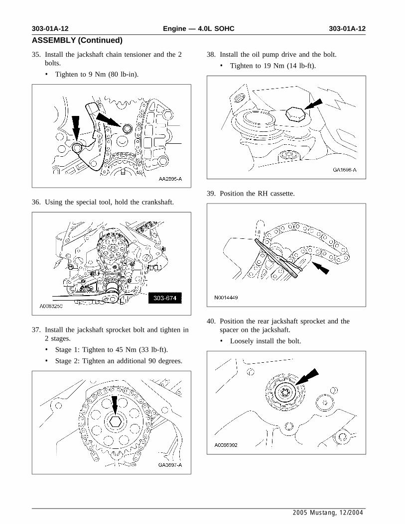
35. Install the jackshaft chain tensioner and the 2 38. Install the oil pump drive and the bolt.bolts. • Tighten to 19 Nm (14 lb-ft).• Tighten to 9 Nm (80 lb-in).
39. Position the RH cassette.36. Using the special tool, hold the crankshaft.
40. Position the rear jackshaft sprocket and the37. Install the jackshaft sprocket bolt and tighten in spacer on the jackshaft.
2 stages. • Loosely install the bolt.• Stage 1: Tighten to 45 Nm (33 lb-ft).
• Stage 2: Tighten an additional 90 degrees.
2005 Mustang, 12/2004

303-01A-13 303-01A-13Engine — 4.0L SOHC
ASSEMBLY (Continued)
41. Install the RH cassette bolt.
• Tighten to 12 Nm (9 lb-ft).
45. Position a new engine front cover gasket on thecylinder block.
46. NOTE: Apply thread sealant to the stud bolts42. Using the special tool, hold the crankshaft.and make sure that the stud bolts are installedin their original positions.
Position the front cover and loosely install the 5bolts and the 5 stud bolts.
43. Tighten the rear jackshaft sprocket bolt in 2stages.
• Stage 1: Tighten to 20 Nm (15 lb-ft).
• Stage 2: Tighten an additional 90 degrees. 47. Use the special tool to align the front cover andtighten the bolts and stud bolts to 19 Nm (14lb-ft).
44. Install the jackshaft plug.
2005 Mustang, 12/2004

303-01A-14 303-01A-14Engine — 4.0L SOHC
ASSEMBLY (Continued)
48. NOTE: Lubricate the seal lip with clean engine 51. CAUTION: Failure to back off the setoil. screws can result in damage to the cylinder
block cradle.Using the special tools, install the crankshaftfront oil seal. Back the set screws off until they are below the
cylinder block cradle boss.
49. Apply silicone gasket and sealant to the frontcover in 4 places. 52. Position the lower block cradle and a new
gasket.
50. Apply silicone gasket and sealant to the rearmain bearing cap as shown. 53. Install and hand-tighten the 20 bolts and 2 nuts.• Position the lower block cradle gasket.
2005 Mustang, 12/2004

303-01A-15 303-01A-15Engine — 4.0L SOHC
ASSEMBLY (Continued)
54. Install and hand-tighten the bolts.
57. Install the 2 block cradle bolts.
• Tighten to 10 Nm (89 lb-in).55. NOTE: The lower block cradle to the cylinder
block alignment must be within a maximummismatch of 0.25 mm (0.01 in) lower blockcradle underflush or 0.05 mm (0.00196 in)lower block cradle protrusion.
Using a straightedge, align the transmission faceof the lower block cradle with the rear face ofthe cylinder block.
58. Tighten the lower block cradle inserts to 3 Nm(27 lb-in).
56. Tighten the 20 bolts and the 2 nuts.
• Tighten the bolts with washers and bothnuts to 10 Nm (89 lb-in).
• Tighten the bolts without washers to 14 Nm(10 lb-ft).
2005 Mustang, 12/2004

303-01A-16 303-01A-16Engine — 4.0L SOHC
ASSEMBLY (Continued)
59. Install new seals on the 2 silver bolts and 62. NOTE: Assemblies that measured out ofloosely install them in the cylinder block cradle. specification must have the entire assembly
procedure repeated.
Measure the step between the rear face of thecylinder block and the transmission face of thelower block cradle.
60. Loosely install the 6 remaining lower blockcradle bolts.
63. Repair all assemblies that exceed underflushspecification by installing shims on 1 or bothsides of the cylinder block cradle.
61. Tighten the cylinder block cradle bolts in 2stages.
• Stage 1: Tighten to 15 Nm (11 lb-ft).
• Stage 2: Tighten to 34 Nm (25 lb-ft).
2005 Mustang, 12/2004

303-01A-17 303-01A-17Engine — 4.0L SOHC
ASSEMBLY (Continued)
64. Install the oil pump screen and pickup tube andthe bolt.
• Tighten to 10 Nm (89 lb-in).
68. Install a new oil filter.
• Tighten until the oil filter seal is flush withthe adapter and the tighten an additional 270degrees.
65. Install the gasket, oil pan and the 10 bolts.
• Tighten to 9 Nm (80 lb-in).
69. Using the special tool, install the crankshaftpulley.
66. Inspect and install new oil filter adapter O-ringseals if necessary.
67. Install the oil filter adapter and the bolt.
• Tighten to 57 Nm (42 lb-ft).
2005 Mustang, 12/2004

303-01A-18 303-01A-18Engine — 4.0L SOHC
ASSEMBLY (Continued)
70. CAUTION: A new bolt must be usedeach time it is removed.
Using the special tool, tighten the bolt in 2stages.
• Stage 1: Tighten to 50 Nm (37 lb-ft).
• Stage 2: Rotate an additional 90 degrees.
73. CAUTION: To avoid damage to thetiming chain cassette, an assistant will berequired to help position the cylinder head inthe vehicle.
NOTE: New cylinder head bolts must beinstalled. They are a torque-to-yield design andcannot be reused.
Position the RH cylinder head. Install 8 new71. Position the crankshaft position (CKP) sensorM12 bolts and tighten in the sequence shown inand install the 2 bolts.2 stages.
• Tighten to 10 Nm (89 lb-in).• Stage 1: Tighten to 12 Nm (9 lb-ft).
• Stage 2: Tighten to 25 Nm (18 lb-ft).
72. NOTE: LH side shown, RH side similar.
Position the cylinder head gaskets.
2005 Mustang, 12/2004

303-01A-19 303-01A-19Engine — 4.0L SOHC
ASSEMBLY (Continued)
74. Install 2 new M8 bolts. 77. CAUTION: The camshaft sprocketmust turn freely on the camshaft. DO NOT• Tighten to 32 Nm (24 lb-ft).tighten the bolt.
Install and hand-tighten the RH rear camshaftsprocket bolt.
75. Tighten the 8 M12 bolts in the sequence shownin 2 stages.
• Stage 1: Tighten 90 degrees.78. Install the RH cassette bolt.• Stage 2: Tighten an additional 90 degrees.
• Tighten to 10 Nm (89 lb-in).
76. Position the RH cassette and camshaft sprocket.
2005 Mustang, 12/2004

303-01A-20 303-01A-20Engine — 4.0L SOHC
ASSEMBLY (Continued)
79. CAUTION: To avoid damage to thetiming chain cassette, an assistant will berequired to help position the cylinder head inthe vehicle.
NOTE: New cylinder head bolts must beinstalled. They are a torque-to-yield design andcannot be reused.
Position the LH cylinder head. Install 8 newM12 bolts and tighten in the sequence shown in2 stages.
• Stage 1: Tighten to 12 Nm (9 lb-ft).
• Stage 2: Tighten to 25 Nm (18 lb-ft). 82. Position the LH cassette and camshaft sprocket.
80. Install 2 new M8 bolts.83. CAUTION: The camshaft sprocket
• Tighten to 32 Nm (24 lb-ft). must turn freely on the camshaft. DO NOTtighten the bolt.
Install and hand-tighten the LH camshaftsprocket bolt.
81. Tighten the 8 M12 bolts in the sequence shownin 2 stages.
• Stage 1: Tighten 90 degrees.
• Stage 2: Tighten an additional 90 degrees.
2005 Mustang, 12/2004

303-01A-21 303-01A-21Engine — 4.0L SOHC
ASSEMBLY (Continued)
84. Install the LH cassette bolt.
• Tighten to 12 Nm (9 lb-ft).
88. NOTE: Leave the top 2 special tool clampbolts loose.
Install the special tools on the rear of the RH85. Turn the crankshaft one revolution clockwise. cylinder head.
86. NOTE: The special tool must be installed onthe damper and should contact the engineblock, this positions the engine at top deadcenter (TDC).
Install the special tool.
89. Install the special tool.
87. NOTE: Camshaft timing slots are off-center.
NOTE: Position the camshaft timing slotsbelow centerline of camshaft to correctly fit thespecial tools.
Install the special tools on the front of the RHcylinder head.
2005 Mustang, 12/2004

303-01A-22 303-01A-22Engine — 4.0L SOHC
ASSEMBLY (Continued)
90. CAUTION: The right-hand camshaftsprocket bolt is a left-hand threaded bolt.
Tighten the bolts.
1 Tighten the special tool top 2 clamp bolts to10 Nm (89 lb-in).
2 Tighten the camshaft bolt to 85 Nm (63lb-ft).
93. NOTE: Camshaft timing slots are off-center.
NOTE: Position the camshaft timing slotsbelow centerline of camshaft to correctly fit thespecial tools.
Install the special tools on the rear of the LHcylinder head.
91. Remove the special tool and install the RHcamshaft tensioner.
• Tighten to 44 Nm (32 lb-ft).
94. Install the special tool.
92. NOTE: Do not tighten the special tool top 2clamp bolts. Camshaft sprocket must rotatefreely.
Install the special tools on the front of the LHcylinder head.
2005 Mustang, 12/2004

303-01A-23 303-01A-23Engine — 4.0L SOHC
ASSEMBLY (Continued)
95. Tighten the bolts. 98. NOTE: Lubricate the roller followers withclean engine oil.1 Tighten the special tool top 2 clamp bolts to
10 Nm (89 lb-in). Using the special tool, install the rollerfollowers in their original positions.2 Tighten the camshaft bolt to 85 Nm (63
lb-ft).
99. Position the RH engine mount bracket andinstall the 4 bolts.96. Install the LH camshaft tensioner.• Tighten to 80 Nm (59 lb-ft).
97. Rotate the crankshaft until the cam lobe is inthe up position. 100. Position a new RH exhaust manifold gasket
and the RH exhaust manifold. Install the 6nuts.
• Tighten to 23 Nm (17 lb-ft).
2005 Mustang, 12/2004

303-01A-24 303-01A-24Engine — 4.0L SOHC
ASSEMBLY (Continued)
101. Position the LH engine mount bracket andinstall the 3 bolts.
• Tighten to 80 Nm (59 lb-ft).
104. Clean the valve covers and cylinder headsealing surfaces with metal surface prep.Inspect and install new gaskets as necessary.
105. Position the RH valve cover and install the 2102. Position a new LH exhaust manifold gasketbolts and the 4 stud bolts.and the LH exhaust manifold. Install the 6
nuts. • Tighten in the sequence shown to 10 Nm(89 lb-in).• Tighten to 23 Nm (17 lb-ft).
106. Position the LH valve cover and install the 3103. NOTE: Install a new O-ring seal on the oilbolts and the 3 stud bolts.level indicator tube and lubricate with clean
engine oil. • Tighten in the sequence shown to 10 Nm(89 lb-in).Position the oil level indicator tube and install
the bolt.
• Tighten to 11 Nm (8 lb-ft).
2005 Mustang, 12/2004

303-01A-25 303-01A-25Engine — 4.0L SOHC
ASSEMBLY (Continued)
107. Position the thermostat housing, hoses and 110. CAUTION: Use O-ring seals that arecoolant tube. Install the 3 bolts. made of special fuel-resistant material. Use
of ordinary O-rings seals can cause the fuel• Tighten to 11 Nm (8 lb-ft).system to leak. Do not reuse the O-ringseals.
NOTE: Lubricate the O-ring seals with cleanengine oil.
Install new O-ring seals on the 6 fuelinjectors.
108. Connect the coolant hose to the coolant pump,position the bracket and install the bolt.
• Tighten to 45 Nm (33 lb-ft).
111. Position the fuel rail and injectors and installthe 4 bolts.
• Tighten to 23 Nm (17 lb-ft).
109. Position the knock sensor and install the bolt.
• Tighten to 20 Nm (15 lb-ft).
2005 Mustang, 12/2004

303-01A-26 303-01A-26Engine — 4.0L SOHC
ASSEMBLY (Continued)
112. Position the main engine wiring harness on the 115. Connect the PCV valve electrical connector.engine and install the 3 bolts.
• Tighten to 40 Nm (30 lb-ft).
• Attach the wiring retainers.
116. Connect the engine coolant temperature (ECT)sensor electrical connector.
113. Connect the 3 RH fuel injector electricalconnectors and attach the wiring retainer to thevalve cover stud bolt.
117. Connect the crankshaft position (CKP) sensorelectrical connector and attach the 2 wiringretainers.
114. Connect the 3 LH fuel injector electricalconnectors and attach the wiring retainer to thevalve cover stud bolt.
2005 Mustang, 12/2004

303-01A-27 303-01A-27Engine — 4.0L SOHC
ASSEMBLY (Continued)
118. Position the generator and bracket. Install the 121. Connect the camshaft position (CMP)2 bolts and the nut. electrical connector.
• Tighten to 47 Nm (35 lb-ft).
122. Position the fuel rail supply tube brackets andinstall the 2 bolts.119. Install the belt tensioner and the bolt.
• Tighten the bolt for the upper bracket to 6• Tighten to 47 Nm (35 lb-ft).Nm (53 lb-in).
• Tighten the bolt for the lower bracket to 10Nm (89 lb-in).
120. Connect the oil pressure sensor electricalconnector and attach the wiring retainer.
2005 Mustang, 12/2004

303-01A-28 303-01A-28Engine — 4.0L SOHC
ASSEMBLY (Continued)
123. NOTE: Clean and inspect all sealing surfaces. 126. Connect the 2 throttle body coolant hoses toInspect and install new intake manifold the coolant tube.gaskets as necessary.
Position the intake manifold and install the 8bolts.
• Tighten in the sequence shown to 10 Nm(89 lb-in).
127. Position the exhaust gas recirculation (EGR)tube. Connect the fitting to the LH exhaustmanifold.
• Tighten to 39 Nm (29 lb-ft).
124. Connect the KS electrical connector and attachthe wiring retainer.
128. Connect the EGR tube fitting to the EGRsystem module.
• Tighten to 39 Nm (29 lb-ft).125. Install the PCV tube.
2005 Mustang, 12/2004

303-01A-29 303-01A-29Engine — 4.0L SOHC
ASSEMBLY (Continued)
129. Connect the EGR system module and throttle 132. Connect the generator and throttle bodyposition (TP) sensor electrical connectors. electrical connectors.
130. Connect the fuel rail pressure and temperature 133. Install the special tool to the RH cylindersensor electrical connector and the vacuum head.tube.
134. Install the special tool to the LH cylinder131. Attach the B+ terminal to the generator and head.
install the nut.
• Tighten to 8 Nm (71 lb-in).
• Attach the wiring retainer to the generator.
2005 Mustang, 12/2004

303-01A-30 303-01A-30Engine — 4.0L SOHC
ASSEMBLY (Continued)
135. Using the special tools, remove the engine 138. Position the crankshaft rear oil seal and thefrom the engine stand. special tool.
136. NOTE: Be sure the crankshaft rear sealing 139. Using the special tool, install the crankshaftsurface is clean and free from any rust or rear oil seal.corrosion. To clean the crankshaft rear sealsurface area, use extra-fine emery cloth orextra-fine 0000 steel wool with metal surfaceprep.
Lubricate the crankshaft rear oil seal withclean engine oil and install it on the specialtool.
140. Install the spacer plate and if equipped, theflexplate-to-crankshaft spacer.
137. Install the special tools.
2005 Mustang, 12/2004

303-01A-31 303-01A-31Engine — 4.0L SOHC
ASSEMBLY (Continued)
141. NOTE: Special bolts are used for flexplateand flywheel installation. Do not use standardbolts.
Install the flexplate or flywheel.
• Tighten the bolts in the sequence shown in2 stages.
X Stage 1: Tighten to 13 Nm (10 lb-ft).
X Stage 2: Tighten to 71 Nm (52 lb-ft).
2005 Mustang, 12/2004