assembly sequence planning for constructing planar...
TRANSCRIPT

Assembly Sequence Planning for Constructing Planar Structureswith Rectangular Modules
Jungwon Seo, Mark Yim, and Vijay Kumar
Abstract— This paper addresses assembly sequence planningfor constructing planar structures of the common brick wallpattern collectively with mobile modular robots that have thesame rectangular footprint. Here we present a new algorithmfor target structures with internal holes that our previous algo-rithm was not able to address. Our new algorithm constructsa feasible assembly sequence where robots do not have topass through narrow corridors while approaching their targetpositions. The algorithm is provably correct and complete andruns in time that is linear in the size of a target structure, that is,the number of its parts. We also present software implementingour algorithms and a set of numerical experiments usingthe software. Finally, we extend our algorithms to addressother symmetric patterns formed by a collection of congruentrectangles on the plane.
I. INTRODUCTION
In this paper, we are concerned with a scenario wherecongruent, rectangular mobile robots are assembled into atarget structure that locally looks like the common brick wall(Fig. 1). Possible applications include constructing floatingstructures on water that can be used for offshore bases fordisaster response, ad hoc landing strips, refueling depots andthe like. Planning relating to the scenario may consist oftwo subproblems. First, one must determine the location towhich a robot can be attached in order to grow the structure.Second, the trajectory of each robot must be planned. Ourfocus is on the first subproblem, determining the sequence ofassembly operations, which can be called assembly sequenceplanning (or assembly sequencing for short). There are off-the-shelf planners that can address the second subproblem,trajectory planning. We integrated the two subproblems intoa full demonstration with hardware [1], but the system wasunable to address target structures with internal holes.
Advanced from our previous work [2], this paper greatlyextends the range of target structures we can assemble bypresenting a new algorithm for target structures with internalholes. Of the combinatorially many sequences for a giventarget structure (m! sequences for a structure with m parts),our algorithm in this paper constructively compute a correct,complete assembly sequence where the robots do not haveto pass through a narrow corridor in the growing structure.In contrast to the previous algorithm that outputs a partialorder, the algorithm presented here outputs a total order.
In order to autonomously assemble a structure, techniquesfor reasoning about geometric interferences among the parts
J. Seo ([email protected]), M. Yim, and V. Kumar are with theDepartment of Mechanical Engineering and Applied Mechanics, Universityof Pennsylvania, Philadelphia, PA, 19104 USA. We gratefully acknowledgethe support of NSF 1328805, 1138847, ARL W911NF-10-2-0016, DARPAHR0011-11-C-0137, and ONR under Grant N00014-09-1-1031.
(a) (b) (c)
Fig. 1. Our cuboid-shaped robotic boats assembled themselves into the(a) landing platform and (b) bridge that locally look like the common brickwall shown in (c).
should be developed. Prior works on robotic assemblyaddressed automated local-scale geometric reasoning [3].However, the local-scale analysis is insufficient to guaranteeaccessibility; for example, parts may have to pass throughnarrow corridors on the way to their target positions, whichmay necessitate difficult maneuvers. It is also imperativeto create efficient algorithms guaranteeing complete, cor-rect assembly and supporting parallel execution, as humanworkers collaboratively construct a brick wall. Decentralizedapproaches to robotic self-assembly presented planning algo-rithms that scale well [4]; however, it can be hard to guar-antee completeness and correctness with such algorithms.
Our algorithms resolve in which order parts, that is, robots,can be assembled into a target structure without gettingstuck in a narrow corridor. The algorithms are provablycorrect, complete and efficient: it takes O(m) time to run thealgorithms (m is the number of the modular units constitutingthe target structure). By following the resulting assemblysequence, a robot does not have to pass through a gap justas large as one side of a robot, flanked by two physicalrobots already assembled in the growing structure, whichwill require difficult maneuvers.
The paper is organized as follows. Sec. II outlines relevantliterature. Sec. III summarizes our previous work. Sec. IVpresents our new algorithm for target structures with internalholes and discusses its correctness. Sec. V presents numericalsimulation. We conclude in Sec. VI. In Appendix, we addressthe generalization of our algorithms.
II. RELATED WORK
Assembly planning is defined as the problem of finding andsequencing the motions that put the initially separated partsof an assembly together to form the assembled product [5].In assembly sequencing, a variant of assembly planning, theparts of an assembly are often assumed to be free-flying; thefocus is on the geometric constraints imposed by the productitself. Some instances of assembly sequencing problemscan be computationally intractible [6]. [7] presented the

hypergraph representation of assembly plans that combinesall feasible assembly sequences; it enables the selection ofthe best assembly plan and parallel execution of assemblyoperations. [3] presented the notion of a non-directionalblocking graph allowing assembly sequences to be computedin polynomial time.
The traditional approach to assembly sequencing hasbeen generalized in many directions. [8] addressed assemblyplanning for toleranced parts. [9] presented a method toconcurrently generate an assembly sequence and design afixture to hold intermediate subassemblies. [10] presentedassembly sequencing that takes part stability into account.Assembly planning can also be understood as a variant ofrobot motion planning [11], [12].
This paper is also relevant to modular self-assembly; herethe focus is on generating a wide range of structures withpossibly congruent modules. For a general survey on thisapproach, refer to [13].
This paper builds on our earlier work presented in [2].
III. PRELIMINARIES
This section briefly reviews our hardware system andassembly sequencing algorithm presented in [1], [2].
A. Hardware Framework
(a)
(b)
Fig. 2. (a) The left panel shows two robots floating on water in a swimmingpool. The right panel shows the bottom of the robot having four waterjetnozzles at the four corners. (b) Robot “He” is docking to another robot(from left to right). This figure also appeared in [2].
The repeated assembly units in this work are mobilerobotic boats having the same rectangular footprint on water(Fig. 2a). The bottom face of a robot is outfitted with a setof four waterjet nozzles that enable holonomic locomotionon the water surface (Fig. 2a). Two robots dock using a maleto female connection mechanism: a hook coming from onerobot engages with a cable loop from the other robot. Tworobots can actually dock to each other only along their longsides (Fig. 2b); they cannot dock along their short sides. Thisarrangement is sufficient for the robots to form the brick wallpattern, as discussed in [2].
Refer to our earlier work [1] for full hardware details.
B. Target Structure
For planning purposes, we model our robotic boats ascongruent rectangles moving on the plane. A target structure
(a)
(b)
C
a
δ
f1f2
Fig. 3. (a) A target structure. Each rectangle represents a site, tobe occupied by a robot. (b) C = (V,E), representing the mechanicalconnectivity of the finally assembled structure, is embedded on the targetstructure. V is the collection of the sites and E consists of unordered pairsof two sites in contact that accommodate two robots mechanically docked.The faces of C, f1 and f2 (except for the smallest faces such as the onecolored blue), are free from narrow corridors in the sense that the rhombuswith the side length δ, three times the length of an edge of C, can travel(illustrated as the traces of the orange rhombus) along the graph edgesto reach every corner; this enables robot a to navigate corridors due toits holonomic locomotion capability (illustrated as the traces of the blackrectangle).
that we want to assemble can be visualized as the collectionof rectangular sites that locally looks like the common brickwall pattern without a gap between two adjacent sites; eachsite is to accommodate a single robot (Fig. 3a).
Target structures are supposed to be connected and freefrom narrow corridors. Given a target structure, consider anundirected graph C = (V,E) that represents the mechani-cal connectivity among robots occupying the member sites(Fig. 3b). If C is connected, we say that the target structureis connected. If there are multiple connected components,they can be assembled individually. Now, embed C on thecorresponding target structure such that the vertices are thecentroids of the sites and the edges are line segments. Foreach face of C, if a rhombus, whose side length is threetimes the length of an edge of C, can reach every pointon the frontier, we say that the face is free from narrowcorridors (Fig. 3b). Note that the smallest faces (such as theone colored blue in Fig. 3b) are exempt from the test becausethe face is in fact not an empty space.
C. Approach
Our intention is to grow a given target structure as oneconnected component by adding one or multiple robotsindividually to the structure in order to sidestep possiblehardware and software complications in controlling anddocking large subassemblies. During assembly, we want toavoid the scenarios shown in Fig. 4 where an incoming robothas to pass through a gap only as large as its side, betweentwo physical robots already assembled in the structure. Thesescenarios may considerably slow down assembly because
an incoming robot can easily get stuck due to wedging orjamming [14]. Not only in a small scale as shown in Fig. 4a,b, the problem can also occur in a larger scale spatially andtemporally: in Fig. 4c, the robot has to pass through thegap with insufficient clearance between a and b in order tooccupy a site not adjacent to a and b (spatial nonlocality);in Fig. 4d, if we want to fill the seven unoccupied sites, atleast the last robot to fill the row has to pass through a gapas large as its side (temporal nonlocality).
(a)
a
b
(b)
a b
(c)
a b
(d)
Fig. 4. (a), (b) The gap between robots a and b can essentially blockthe incoming robot. (c) The gap between a and b can affect assembly thathappens at a distance spatially. (d) If we want robots to occupy the sevenopen sites, at least the last robot has to pass through a narrow gap.
D. Assembly Sequencing Algorithm for Parallel Assembly
In [2], we presented an assembly sequencing algorithmthat can be applied to target structures without internal holes.The algorithm returns a directed acyclic graph that representsa feasible assembly sequence without the issues illustrated inFig. 4; see Fig. 5. It can be shown that the algorithm runs inO(m) time (not in O(m2) time as discussed in [2]), wherem is the number of the member sites, by considering thateach site has at most O(1) neighboring sites.
11 10 12 15 7 6 8 16 14
......
0
1
2
3
4
9
8
7
6
5
12
17
16
15
14
13
18
19
20
21
22
11
10GA
GA
(a)
(b)
Fig. 5. (a) Given the target structure (the collection of the rectangularsites), the algorithm presented in [2] returns GA, a directed acyclic graphrepresenting the resulting assembly sequence. (b) The same graph as (a),but topologically sorted. The sites grouped in each dotted boundary can beoccupied simultaneously once the preceding groups are occupied.
An actual assembly proceeds with the partial order estab-lished by the directed edges of the resulting graph. The struc-ture grows as a single connected component and multiplerobots can dock to the structure in a parallel, decentralizedmanner (Fig. 5b).
IV. ALGORITHM FOR TARGET STRUCTURES WITH HOLES
Here we present a new assembly sequencing algorithmfor target structures with internal holes that the previousalgorithm explained in Sec. III-D was not able to address.By following the resulting sequence, it is also possible tocompletely avoid the issues in Fig. 4.
A. Algorithm
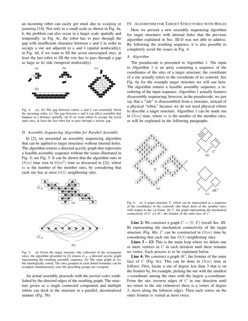
The pseudocode is presented in Algorithm 1. The inputto Algorithm 1 is an array containing a sequence of thecoordinates of the sites of a target structure; the coordinateof a site actually refers to the coordinate of its centroid. SeeFig. 6a for the example target structure we will use here.The algorithm returns a feasible assembly sequence, a re-ordering of the input sequence. Algorithm 1 actually featuresdisassembly sequencing; however, in the pseudocode, we justsay that a “site” is disassembled from a structure, instead ofa physical “robot,” because we do not need physical robotsto describe a target structure. Algorithm 1 can be made runin O(m) time, where m is the number of the member sites,as will be explained in the following paragraphs.
(a)
x
y
T
(b)C
(c)∂C
Fig. 6. (a) A target structure T , which can be represented as a sequenceof the coordinates of the centroids (the black dots) of the member sites,with respect to the xy-frame. (b) C, the graph representing the mechanicalconnectivity of T . (c) ∂C, the frontier of the outer face of C.
Line 2: We construct a graph C = (V,E) (recall Sec. III-B) representing the mechanical connectivity of the targetstructure (Fig. 6b). C can be constructed in O(m) time byconsidering that each site has O(1) neighboring sites.
Lines 3 – 13: This is the main loop where we delete oneor more vertices in C in each iteration until there remainsno vertex. Each process is to be explained below.
Line 4: We construct a graph ∂C, the frontier of the outerface of C (Fig. 6c). This can be done in O(m) time asfollows. First, locate a site of degree less than 3 that is onthe frontier by, for example, picking the site with the smallestx-coordinate among the ones with the largest y-coordinate.From the site, traverse edges of C in one direction untilwe return to the site (whenever there is a vertex of degree3, move along the leftmost edge). Then each vertex on theouter frontier is visited at most twice.

Algorithm 1 ASSEMBLY-SEQUENCING(T )
Input: Target structure T : a sequence of sites to be occu-pied, T = 〈s1, s2, · · · , sm〉.
Output: Assembly sequence A: a permutation of T .1: Let A be an empty stack.2: Construct C.3: while C is not a null graph do4: Construct ∂C.5: if ∂C has a vertex of degree 1, say si, then6: Push si to A.7: C = C − si8: else9: Search for a block of ∂C that contains only one
cutvertex of ∂C; establish a sequence of sites〈si, sj , sk〉 to be disassembled from the block.
10: Push si, sj , and sk to A.11: C = C − {si, sj , sk}12: end if13: end while14: Return A.
Lines 6 – 7: If ∂C has a vertex of degree 1, the vertexis pushed to the stack A (Line 1) and deleted from C alongwith any incident edges (Fig. 7). These operations can bedone in O(m) time.
∂C updated Cs
Fig. 7. Since ∂C has a vertex of degree 1, s, the vertex is to bedisassembled. The next iteration starts with the updated C.
Lines 9 – 11: A block of a graph is either a maximal 2-connected subgraph, or a bridge, or an isolated vertex. For∂C here that does not have a vertex of degree less than 2,we can always find a block with one or no cutvertex of theoriginal graph; moreover, such a block must be a cycle (seeLemma 1 for the proof). We pick such a cycle, either B1or B2 in Fig. 8a, and establish a sequence of sites that canbe disassembled from the cycle as follows. Suppose that wepicked B1. Consider the site with the smallest x-coordinateon the row of the largest y-coordinate; the site is denotedas si in Fig. 8b. Next, we inspect if a site si,SE (SE standsfor “southeast” with respect to the reference frame shown inFig. 8a; consider the positive y-direction as the north) is avertex of C or not. If so, we establish a sequence 〈si〉 as thepotential output of this line. If not, as can actually be seenin Fig. 8b, we pick two more sites, sj and sk, and establish〈si, sj , sk〉 as the potential output. We can repeat the processby letting si be the site with the largest x-coordinate onthe row of the smallest y-coordinate (Fig. 8c): we inspect
(a)
∂C
x
y
B1
B2
(b)
B1
updated C
sisjsksi,SE
(c)
B1
updated C
sksjsi
si,NW
(d)
B2
updated C
si
si,SE
(e)
B2
sisj
sksi,NW
Fig. 8. (a) ∂C currently has two blocks that are cycles, denoted as B1 andB2. Each red vertex is a cutvertex of ∂C that belongs to B1 or B2. (b), (c)Suppose that we picked B1. si, sj , and sk can potentially be disassembledfrom the structure; C will then be updated as the graph shown below. In casewe picked B2, (d) si can potentially be disassembled from the structure; (e)because sk is the cutvertex, the sequence 〈si, sj , sk〉 will not be returned.
if a site si,NW (NW stands for “northwest” with respect tothe reference frame) is a vertex of C or not, as illustratedin Fig. 8c; according to the result, we establish either 〈si〉or 〈si, sj , sk〉 as the potential output in a similar manner.Between the two sequences established for the potentialoutput, pick one without the cutvertex for the output of Line9. In Lines 10 – 11, we push si (or si, sj , and sk in theorder enumerated) to A; we then delete si (or si, sj , and sk)from C along with any incident edges. These lines can bedone in O(m) time: blocks and cutvertices can be computedin O(m) time [15].
Remark: We get an assembly sequence by poppingelements from A. In contrast to our previous algorithmexplained in Sec. III-D that outputs a partial order, the outputof Algorithm 1 is a total order on the member sites, whichallows us to assemble the target structure by occupying themember sites one by one.
B. Analysis
We here discuss the completeness and correctness ofAlgorithm 1: it terminates and returns a feasible assemblysequence without the issues illustrated in Fig. 4.
Lemma 1: Line 9 of Algorithm 1 returns a nonemptysequence.
Sketch of proof: It can be shown that there exists a blockof ∂C with one or no cutvertex and the block is a cycle.In Line 9, we then get two distinct, non-empty sequences ofsites to be disassembled from the block; one of the sequences

can always be returned as the output of Line 9. For fulldetails, refer to Lemma 4 in Chapter 11 of [16]. �Lemma 1 ensures that the number of vertices of C keepsdecreasing as we iterate the process of Lines 4 – 12; thus,Algorithm 1 terminates.
Lemma 2: At the start of each iteration of the while loopin Algorithm 1, C satisfies the assumptions stated in Sec. III-B: C is connected and free of narrow corridors.
Sketch of proof: We verify the following two items tosee the property holds as a loop invariant: (1) Initializa-tion (the property is true prior to the first iteration); (2)Maintenance (if the property is true before an iteration, itremains true before the next iteration). For full details, referto Lemma 5 in Chapter 11 of [16]. �
When Algorithm 1 terminates, C is a null graph. There-fore, Lemma 2 guarantees that when we assemble a structureaccording to the computed assembly sequence, the structuregrows from a single seed robot as a single connectedcomponent always satisfying the assumptions of Sec. III-B.
Because assembly happens only on ∂C, a robot canreach a site open for occupancy without being blocked bya physical wall or a narrow corridor. In addition, our lastlemma ensures that a site open for occupancy is not flankedbetween two physical robots already docked in the structure.
Lemma 3: In each iteration of the while loop in Algo-rithm 1, each disassembly event can be performed such thatthe site to be disassembled is not located between two othersites that form a gap as large as a side of a site.
Proof: If a site to be disassembled is a vertex of degree1 in ∂C (Lines 6 – 7), the site has at most one neighbor.Thus, the site is not located between two other sites. In Lines9 – 11, if we disassemble si, sj , and sk one at a time in theorder enumerated, each of them is not flanked by two othersites that form a gap as large as a side of a site.
V. IMPLEMENTATION AND EXPERIMENT
We wrote a software package1 that implements our al-gorithms, presented in Sec. III-D, IV, written in C++. Thesoftware, which we call the Assembly Sequence Planner,parses a blueprint for a target structure and returns anassembly sequence that specifies a partial/total order forfilling the sites of the target structure. Given the shape ofthe current structure, the software is capable of returningopen site(s) that can be occupied simultaneously aroundthe current structure. The Assembly Sequence Planner is apart of a software suite [1] that operates the robotic boatsintroduced in Sec. III-A.
Fig. 9a, b show target structures composed of 207 and435 member sites that look like the continental United States(Fig. 9a, also appeared in [2]) and a row of piers in a harbor(Fig. 9b). It took 0.007/0.015 seconds on average for thesoftware running on a 4GB, 2.53 GHz machine to computeassembly sequences for the examples. Fig. 9c shows somesnapshots illustrating the assembly sequences for the threetarget structures with holes: letters ‘R’ and ‘B,’ each of which
1Available at http://www.seas.upenn.edu/˜juse
is composed of 46 sites, where it took 0.03s to compute eachassembly sequence; a structure (composed of 156 sites) with25 holes where it took 0.14s.
Given a target structure without holes, our software alsoallows us to find the optimal assembly sequence where theresulting directed acyclic graph has the least height, thelength of the longest path between the root and a leaf. Byminimizing the height, it is possible to make the most of theparallelism of a swarm of the robotic boats, which can resultin the fastest assembly time. For a target structure with mmember sites, it takes O(m2) time to compute the optimalsequence: we repeatedly apply our previous algorithm [2],running in O(m) time, designating each member site as theseed; finding the height of the resultant graph can be donein O(m) time using a breadth-first search. For example, ifwe start assembling the structures of Fig. 9a, b from thesites colored red in the left panels, we can get the “shortest”assembly sequences. For the USA example (Fig. 9a), theminimum height was 31. Suppose that sites are occupiedimmediately as soon as they are discovered by the software.We could then assemble maximally 11 robots at a time,by following the optimal sequence. For the harbor example(Fig. 9b), the minimum height and the maximum growthrate were 57 and 13, respectively. Note that the snapshots ofFig. 9a, b do not show the progress of the optimal sequence.
The results of the above experiments are summarizedin Table I. We also built real structures with our hard-ware/software implementation; see [1] for details.
VI. CONCLUSION
We have presented our progress on developing provablycorrect and complete assembly sequence planning algorithmsfor constructing planar target structures with congruent,rectangular mobile units. Our algorithms compute a feasibleassembly sequence, represented as a partial or total order,in linear time. The resulting sequence guarantees that a freerobot does not have to pass through a narrow gap whileapproaching its target position. In APPENDIX, we generalizethe algorithms to other symmetric patterns. Our future workwill address a wider range of target structures includingthree-dimensional structures and vertical walls/buildings, byincorporating static/dynamic stability analysis.
APPENDIX: EXTENSION TO OTHER PATTERNS
On the plane, there are 17 distinct groups that classifyrepetitive patterns based on their symmetries; the groups arecalled plane symmetry groups. [17] showed how six of the17 groups can be produced by tessellating the plane withcongruent rectangles. Our assembly sequencing algorithmscan be applied to not only the common brick wall patterndiscussed in this paper (Fig. 10a) but also five other patterns(Fig. 10b, c, d, e, f); for more details, we refer readers toChapter 13 of [16].
REFERENCES
[1] J. Paulos, N. Eckenstein, T. Tosun, J. Seo, J. Davey, J. Greco,V. Kumar, and M. Yim, “Automated self-assembly of large maritimestructures by a team of robotic boats,” Automation Science andEngineering, IEEE Transactions on, vol. 12, pp. 958–968, July 2015.

(a)
(b)
(c)
Fig. 9. (a) Assembling the target structure composed of 207 member sites, which looks like the continental United States. (b) Assembling the targetstructure composed of 435 member sites, which looks like the harbor. (c) Assembling the two letters with holes: ’R’, ’B’ with Lego blocks, which dockin the same manner as our robotic boats; assembling the structure with 25 holes.
(a) (b) (c)
(d) (e) (f)
Fig. 10. The left figures of (a) – (f) illustrate six symmetric patterns that can be generated by congruent rectangles. The right figures of (a) – (f) illustratethe target structure of Fig. 5 in each of the patterns.
Computation timeTarget Sites Individual (average) Optimal Minimum height Maximum growth rateUSA (Fig. 9a) 207 0.007s 1.68s 31 11 robotsharbor (Fig. 9b) 435 0.015s 10.75s 57 13 robots100-by-100 square 10,000 0.607s 7604.26s 248 84 robots
TABLE ITHE RESULTS OF ASSEMBLY SEQUENCING EXPERIMENTS. FOR THE OPTIMAL PLANS, WE ITERATED OVER ALL MEMBER SITES FOR THE USA AND
HARBOR EXAMPLES; WE SAMPLED 500 SITES FOR THE 100-BY-100 SQUARE.
[2] J. Seo, M. Yim, and V. Kumar, “Assembly planning for planarstructures of a brick wall pattern with rectangular modular robots,”in Automation Science and Engineering (CASE), 2013 IEEE Interna-tional Conference on, pp. 1016–1021, IEEE, 2013.
[3] R. H. Wilson and J.-C. Latombe, “Geometric reasoning about me-chanical assembly,” Artificial Intelligence, vol. 71, no. 2, pp. 371–396,1994.
[4] M. Yim, Y. Zhang, J. Lamping, and E. Mao, “Distributed control for3d metamorphosis,” Autonomous Robots, vol. 10, no. 1, pp. 41–56,2001.
[5] D. Halperin, J.-C. Latombe, and R. H. Wilson, “A general frameworkfor assembly planning: The motion space approach,” Algorithmica,vol. 26, no. 3-4, pp. 577–601, 2000.
[6] L. E. Kavraki and M. N. Kolountzakis, “Partitioning a planar assemblyinto two connected parts is np-complete,” Information ProcessingLetters, vol. 55, no. 3, pp. 159–165, 1995.
[7] L. S. Homem de Mello and A. C. Sanderson, “And/or graph representa-tion of assembly plans,” Robotics and Automation, IEEE Transactionson, vol. 6, no. 2, pp. 188–199, 1990.
[8] Y. Ostrovsky-Berman and L. Joskowicz, “Relative position com-putation for assembly planning with planar toleranced parts,” TheInternational Journal of Robotics Research, vol. 25, no. 2, pp. 147–170, 2006.
[9] B. Romney, “Atlas: An automatic assembly sequencing and fixturing
system,” in Geometric Modeling: Theory and Practice, pp. 397–415,Springer, 1997.
[10] S. Rakshit and S. Akella, “The influence of motion paths and assemblysequences on the stability of assemblies,” IEEE Transactions onAutomation Science and Engineering, vol. PP, 2014.
[11] S. Sundaram, I. Remmler, and N. M. Amato, “Disassembly sequencingusing a motion planning approach,” in Robotics and Automation, 2001.Proceedings 2001 ICRA. IEEE International Conference on, vol. 2,pp. 1475–1480, IEEE, 2001.
[12] D. T. Le, J. Cortes, and T. Simeon, “A path planning approach to (dis)assembly sequencing,” in Automation Science and Engineering, IEEEInternational Conference on, pp. 286–291, IEEE, 2009.
[13] M. Yim, W.-M. Shen, B. Salemi, D. Rus, M. Moll, H. Lipson,E. Klavins, and G. S. Chirikjian, “Modular self-reconfigurable robotsystems [grand challenges of robotics],” Robotics & AutomationMagazine, IEEE, vol. 14, no. 1, pp. 43–52, 2007.
[14] M. T. Mason, Mechanics of robotic manipulation. MIT press, 2001.[15] R. Tarjan, “Depth-first search and linear graph algorithms,” SIAM
journal on computing, vol. 1, no. 2, pp. 146–160, 1972.[16] J. Seo, Grasping and Assembling with Modular Robots. PhD thesis,
University of Pennsylvania, 2014.[17] H. S. M. Coxeter, Introduction to geometry. New York, London, 1961.