assembly & maintenance - interactive intelligencewouter/helipage/docs/raptor/50v2med.pdf ·...
TRANSCRIPT

ASSEMBLY & MAINTENANCE
50 Size 3D Heli
Version 2.0

0
NOTICE
This is an electronic duplicate of the Thunder Tiger Manual for the Raptor 50 V2 kit. In contrast
with the Raptor 30 manuals, a Raptor 50 manual has never been made available in electronic
form by Thunder Tiger. Therefore this manual was constructed partly by scanning in parts and by
manually creating the pages, and partly by copying and modifying the Raptor 30 V2 manual. I did
a very careful job in duplicating the manual, but of course I can not assume responsibility in case
of errors.
The duplicate has been kept as close as possible to the original manual, but at numerous places
errors and typos were corrected. At many places the English text was improved, as well as the
layout. Some part numbers have been corrected. A few sentences where correction would need
more than changing a few words were left unchanged.
The front page has been recreated in color, where the original manual is all black and white. A
colored front page is so much more inviting!
I hope you enjoy the use of this electronic manual.
June 2003
Wouter Pasman
Netherlands.

1
INTRODUCTION
Congratulations on your purchase of the Thunder Tiger Raptor 50 V2 helicopter. This model was
designed and engineered by the World-renowned Mr. Shgetada Taya. It combines elements of
his previously successful designs with today's advanced technologies.
Raptor 50: the best 50 class 3-D helicopter is now even better! The Raptor 50 V2 is the
cumulating result from all customers' feedback and tremendous research and development effort
by the Thunder Tiger design team. The Raptor 50 V2 is more rugged and has even better flying
performance than the original successful Raptor 50. The Raptor 50 V2 has the best power-to-
weight ratio of any 50 class helicopter on the market. Buckle your seatbelt and get ready for
incredibly fast accelerations and climb rate. With the new main rotor, 3-D pilots will enjoy
executing crisp maneuvers like Climbing Tic-Toc, Chaos, Death Spirals, and any radical
maneuver that pilots can dream of. Key new features include stronger mainframes, bigger fuel
tank, reinforced pitch control arm, new main rotor with 6 mm spindle and bigger radial and thrust
bearings, and a fresh new look body. The V2 includes a constant drive auto rotation gear for
doing aerobatics during autorotation. Beginners and advanced 3-D fliers will be very impressed
with the new Raptor 50 V2.
CONTENTSIntroduction...............................................p.1Contents ...................................................p.1Warnings ..................................................p.1Additional Items Needed...........................p.3Tools Needed ...........................................p.3
Assembling Section..................................p.4Linkage Set-up Section ............................p.18Blade Modification ....................................p.26Parts List Section......................................p.28
WARNINGThis radio controlled helicopter is not a toy. It is a sophisticated piece of equipment and is
designed for hobby use only. If not properly assembled and operated, it is capable of causing
property damage and bodily harm to both the operator and/or spectators. Thunder Tiger and its
duly authorized distributors assume no liability for damage that could occur from the assembly
and/or use/misuse of this product.
AMA INFORMATIONOperating a model helicopter requires a high degree of diligence and skill. If you are a newcomer
to the hobby, it is best to seek help and guidance from accomplished model helicopter pilots.
This will greatly speed up the learning process and have you flying successfully in a reasonable
time. We also would strongly urge you to join the Academy of Model Aeronautics. The AMA is a
non-profit organization that provides its members with a liability insurance plan as well as
monthly magazine entitled Model Aviation. All AMA charter aircraft clubs require all pilots to hold
a current AMA sporting license prior to operation of their models at club fields. For further
information, contact the AMA at:
Academy of Model Aeronautics
5151 East Memorial Drive
Muncie, IN 47302
(317) 287-1256
2
FLIGHT SAFETY CHECKLIST
1. Make sure both the transmitter and receiver batteries are fully charged prior to operation the
helicopter.
2. Make sure all flight controls operate properly prior to flying.
3. Range check the radio before the first flight. The servos must operate properly with the
transmitter antenna collapsed at a range of at least 50 ft.(15 meters).
4. Check to make sure there is no radio interference on your radio channel before operating the
helicopter.
5. Use only the recommended engine fuel as specified by the engine manufacturer.
6. Make sure the transmitter and receiver are turned on before starting the engine.
7. The engine throttle must be in the idle position before starting the engine.
8. Model helicopter main and tail rotors operate at high RPM. Make sure nothing can come in
contact with the rotor blades during flight.
9. After starting the helicopter, maintain a safe distance during the flight.
10. Never operate the helicopter in rain or excessive wind conditions.
11. Always operate and fly your helicopter in a safe and responsible manner.
12. Never fly a model helicopter over other pilots, spectators or cars.
POST FLIGHT INSPECTION
1. Inspect the model thoroughly to insure no parts have come loose or become damaged during
the flight and landing. Replace damaged parts and tighten loose screws before flying again.
2. Pump out any remaining fuel from the fuel tank.
3. Wipe off excess oil and fuel from helicopter body and other exposed parts.
4. Lubricate all moving parts ensures smooth operation for the next time you fly.
5. Store model in a cool, dry place. Avoid storage in direct sunlight or near a source of heat.
Following these few, simple safety rules will allow you to enjoy the thrill of model helicopter flying
for many years to come.
SAFETY CHECKLISTCAUTION: In the event the model has crashed, inspect the flybar, rotor shaft and the blade spindle to
make sure they are not bent at all. If any item is damaged, it must be replaced with a new part to ensure
safe operation. Do not glue any broken or damaged plastic part. Do not repair broken rotor blades. Always
inspect the following items immediately:
Engine starting shaft.
All the gears.
Main shaft, flybar and blade spindle.
Tail boom and support.
Vertical and horizontal fins.
Tail rotor shaft and control system.
Main and tail rotor blades.
3
TOOLS REQUIRED FOR ASSEMBLY
OTHER ITEMS REQUIRED
Receiver
Transmitter(helicopter type only6 or more channels)
Servo x 5
Battery1000mAh
Switch harness
Extended 6mm Hex
Starting Tool
Fuel Pump
HELI ENGINE(50-size)
Socket Drivers
Hex WrenchGrease
Blue LocktiteInstant Glue
Hobby Knife
Metric4-way WrenchScissorsNipper5.5mm WrenchNeedle Nose PliersScrew Driver
Glow Plug Wrench
Gyro
Glow Fuel(15%-30%)
12V Battery
1.5V Glow starter(1.2V~1.5V)
Rubber Band
Foam
RADIO SET
ENGINE
Glow Plug
12V Electric starter
7mm
5.5mm7mm8mm
5.5mm7mm8mm
10mm
Remote Glow Plug
Extension
Epoxy
Ball Link Pliers
4
ASSEMBLING SECTION
Most parts in the Raptor kit are packed according to the assembly steps. The part number and quantity containedin each step are always shown in the square box on each page. Do not open all the bags at once. Open only thebag that is needed for the current assembly step.
(3 )BK0463
(2 )BK0062
(5 )CB0363-1
(4 )BE1867
(1) BK0605
To Header Tank
(6) BB362-2
(6) BB362-2
To Muffler
5
2 Clutch Bell Assembly
1 Fuel Tank Assembly
(1)BK0605 Fuel Tank .....................1
(2)BK0062 Fuel Tank Grommet.......1
(3)BK0463 Fuel Tank Nipple .......... 1
(4)BE1867 Clunk.............................1
(5)CB0363-1 Silicone Fuel Tube.....1
(6)BB0362-2 Silicone Fuel Tube..... 2
Note: After assembly, check to make sure the Fuel Tankclunk can move from top to bottom without touching theback of tank. Also, a fuel filter (available from any hobbyshop, TTR1164) should be placed between the fuel tankand the carburetor.
(1) HMV1680 Bearing (d8xD16xW5).....1
(2) HMV1260Y Bearing (d6xD12xW4)...1
(3) BK0591 Clutch Bell..........................1
(4) BK0624 Drive Gear(Pinion 10T)......1
(5) BK0590 Clutch Liner........................1
(1) HMV1680
(4) BK0624
(3) BK0591
(2) HMV1260Y
(5) BK0590The liner comes glued in theclutch bell already.
Connect the fuel tube toheader tank(See Page 13 Step. 15)
(10) BK0600
(14) BK0594
(6) HME4-5B
(1) HSE3-12B
(2) HMV696ZTop Starter ShaftBearing
(1) HSE3-12B
(8) BK0057
(15) Fuel Tank Ass'y
(16) Clutch BellAssembly
(13) BK0592
(3) HMV6800 Upper Main Shaft bearing
(4) BK0059 Main Frame Spacer(S)
(5) BK0058 Main Frame Spacer (L)
(11) BV0035
(1) HSE3-12B
(3) HMV6800Lower Main Shaft Bearing
(9) BK0599
(7) BK0081
(12) BK0036
6
3 Main Frame Assembly-Part1
(1) HSE3-12B Self Tapping Screw (M3x12).. 30
(2) HMV696Z Bearing (d6xD15xW5).......... 1
(3) HMV6800 Bearing (d10xD19xW5).......... 2
(4) BK0059 Frame Spacer (S)....................... 8
(5) BK0058 Frame Spacer (L)...................... 4
(6) HME4-5B Set Screw (M4x5)................... 2
(7) BK0081 Pin............................................. 2
(8) BK0057 Servo Frame.............................. 1
(9) BK0599 Main Frame Left Side.............. 1
(10) BK0600 Main Frame Right Side..........1
(11) BV0035 Guide Pulley.......................... 2
(12) BK0036 Pulley Collar.......................... 4
(13) BK0592 Starter Shaft.......................... 1
(14) BK0594 Starter Coupling.................... 1
(15) Fuel Tank Assembly
(16) Clutch Assembly
(17) HMS5 E-CLIP..................................... 1
(18) BK0584 Thrust Washer.......................1
Please insert the frame spacers, bearings, pulley and parts in the frames according the drawing below. Tighten thescrews snugly, but do not over torque them which could strip the plastic.Insert starter shaft through the center of the clutch bell assembly, through the top starter shaft bearing and into thestarter coupling. Secure with the two set screws. Make sure this is tightly secured.
(17) HMS5
(18) BK0584
(3) HMV740ZZ
(4) BK0077
(5) BK0079
(6) BK0075
(7) BK0015
(8) BK0016(9) BK0014
(1) HMJ2-10N
(2) HMC3-10B
(3) HMV740ZZ(1) HMJ2-10N
(8) BK0016
(3) HMV740ZZ
(5) BK0079
(6) BK0075
(3) HMV740ZZ
(4) BK0077
(2) HMC3-10B
(7) BK0015
7
4 Main Drive Gear Assembly(1) HMC3-8B Socket Screw (M3x8)............. 4
(2) HMQ14 Snap Ring.................................... 2
(3) BV0033 One Way Clutch Housing.............1
(4) BK0148 Main Spur Gear 85T.....................1
(5) BK0610 Autorotation Tail Drive Pulley ..... 1
(6) BK0034 One Way Clutch Shaft..................1
5 Washout Assembly(1) HMJ2-10N Self Tapping Screw(M2x10).. 2
(2) HMC3-10B Socket Screw (M3x10)......... 2
(3) HMV740ZZ Bearing (d4xD7xW2.5)........ 4
(4) BK0077 Collar ........................................ 2
(5) BK0079 Pin............................................. 2
(6) BK0075 Linkage Ball.............................. 2
(7) BK0015 Flybar Control Lever.................. 2
(8) BK0016 Washout Linkage ..................... 2
(9) BK0014 Washout Base............................1
Make sure Linkage Balls are attached to theinside hole of each stabilizer control lever.
(1) HMC3-8B
(6) BK0034
(2) HMQ14
(5) BK0610
(4) BK0148
(2) HMQ14
(3) BV0033
Add a drop of Blue Locktite on thethread of each of these four screws.
Add some lightweight oil beforeinserting this intoBV0033
8
6 Main Frame Assembly-Part2Add a drop of CA to the two screws at the pivoting point of the collective pitch control arm.Attach the linkage rod to the parallel elevator linkage balls.
(1) HSE3-18B
(2) HSE3-12B
(3) HMJ3-22B
(4) HMJ2-14N
(5) HMJ2-10N
(6) HMV1280
(7) HMV740ZZ
(8) HMV840ZZ
(9) BK0076
(10) BK0078
(1) HSE3-18B(12) BK0084
(13) BK0075
(14) BK0023
(15) BK0018
(16) BK0020
(17) BK0022
(18) BK0019
(20) BK0093
(21) BK0021
(22) BK0017
(14) BK0023
(7) HMV740ZZ
(5) HMJ2-10N
(13) BK0075
(8) HMV840ZZ(10) BK0078
(11) BK0088(7) HMV740ZZ
(13) BK0075(7) HMV740ZZ
(9) BK0076
(6) HMV1280
(13) BK0075
(1) HSE3-18B
(5) HMJ2-10N
(7) HMV740ZZ
(5) HMJ2-10N
(13) BK0075
(7) HMV740ZZ
(9) BK0076
(1) HSE3-18B
(19) BK0086
Warning, do not over-torque the self-tapping screws.
(1) HSE3-18B Self Tapping Screw(M3x18)....4
(2) HSE3-12B Self Tapping Screw(M3x12)... 1
(3) HMJ3-22B Self Tapping Screw(M3x22)....1
(4) HMJ2-14N Self Tapping Screw(M2x14)... 1
(5) HMJ2-10N Self Tapping Screw(M2x10)... 6
(6) HMV1280 Bearing (d8xD12xW3.5)......... 2
(7) HMV740ZZ Bearing (d4xD7xW2.5)........ 6
(8) HMV840ZZ Bearing (d4xD8xW3)............ 2
(9) BK0076 Collar......................................... 3
(10) BK0078 Collar ...................................... 2
(11) BK0088 Flat Washer ......................... 1
(12) BK0084 Pin .......................................... 2
(13) BK0075 Linkage Ball..............................8
(14) BK0023 Elevator Control Arm Link........ 2
(15) BK0018 Elevator Control Arm................ 1
(16) BK0020 Elevator Arm Control Shaft.......1
(17) BK0022 Aileron Control Lever................ 2
(18) BK0019 Elevator Arm Parallel Lever...... 1
(19) BK0086 Ball Link....................................2
(20) BK0093 Linkage Rod ............................ 1
(21) BK0021 Elevator Control Lever..............1
(22) BK0017 Collective Pitch Control Arm.....1
66mm
7 Main Frame Assembly-Part3
58mm
(1) BK0616 Socket Screw(M3x20)............1
(2) HMM3Z Lock Nut (M3)........................ 1
(3) HME4-5B Set Screw (M4x5)............... 2
(4) BK0086 Ball Link ................................ 4
(5) BK0092 Linkage Rod ......................... 2
(6) BK0030 Main Shaft Lock Ring............ 1
(7) BK0029 Main Shaft ............................ 1
(8) Wash Out Assembly
(9) BV0092 Swash Plate Assembly...........1
(10) Main Gear Assembly
Insert Main Shaft through the shaft bearings making sure that the end with the holes closest to the end ispointed down. Next, slide main gear assembly into position on the shaft and line up the holes in the mainshaft with the holes in one way clutch shaft of the main gear assembly. Insert the socket head screw andsecure with the lock nut. Next, slide on the mainshaft lock ring on top of the main shaft bearing and securewith the two set screws. Then slide on the swash plate assembly and attach the elevator and aileroncontrol linkages to the outside swash plate linkage balls. Next, slide on washout assembly and attachwashout linkage to the inner linkage balls of the swash plate.
(1) BK0616(2) HMM3Z
(3) HME4-5B
(6) BK0030
(7) BK0029
(9) BV0092
(10) Main Gear Assembly
(8) Washout Assembly
(4) BK0086
(5) BK0092
(4) BK0086
8 Engine Assembly
(1) HMC3-10B Socket Screw(M3x10)..... 2
(2) BV0589 Clutch Shoe..........................1
(3) BV0143 Cooling Fan.......................... 1
(4) No.9605 TT PRO-50H(R) Engine.......1
(5) BK0170 Shim.....................................1
Note: A piston lock (TTR1166P) purchased from your dealer willmake this a much easier task. You must replace the standardthrottle arm w/the extended throttle arm and attach the linkageball.
9
(1) HMC3-10B
(4) No.9605
(3) BV0143
(1) HMC3-10B
Add Blue Locktite
Linkage Ball to
throttle Arm
(2) BV0589
(5) BK0170
Tighten the enginenut securely bygrabbing the plasticfan with a towel.
(5) BV0172(6) Engine Ass'y.
(3) BK0087
(1) HMC3-14B
(2) HMC3-35BAdd Blue Locktite
(3) BK0087
Add Blue Locktite
Engine mount
Attachment(1) HMC3-14B
(1)
(3) BK0087
(3) BK0087
(7) BA1579
HMC3-14B
Add BlueLocktite
10
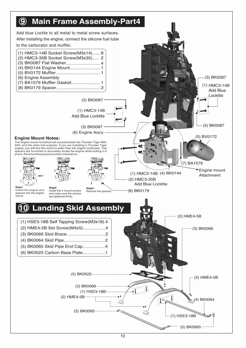
(1) HMC3-14B Socket Screw(M3x14)...... 8(2) HMC3-35B Socket Screw(M3x35)..... 2(3) BK0087 Flat Washer........................... 4(4) BK0144 Engine Mount........................ 1(5) BV0172 Muffler ................................... 1(6) Engine Assembly(7) BA1579 Muffler Gasket.......................
Add blue Loctite to all metal to metal screw surfaces.
After installing the engine, connect the silicone fuel tube
to the carburator and muffler.
9 Main Frame Assembly-Part4
10 Landing Skid Assembly(1) HSE3-18B Self Tapping Screw(M3x18).4
(2) HME4-5B Set Screw(M4x5)..................4
(3) BK0066 Skid Brace...............................2
(4) BK0064 Skid Pipe.................................2
(5) BK0065 Skid Pipe End Cap..................4
(3) BK0066
(2) HME4-5B
(5) BK0065
(1) HSE3-18B
(4) BK0064
(2) HME4-5B
(3) BK0066
(2) HME4-5B
(1) HSE3-18B
(6) BK0525 Carbon Base Plate..................1
(5) BK0065
The engine mount furnished will accommodate the Thunder Tiger 46H,50H, and the other heli engines. If you are installing a Thunder Tigerengine, you will find the mount is wider than the engine crankcase. Twospacers are furnished to accurately locate the engine while bolting it inplace. Remove these spacers after installation.
Engine Mount Notes:
Step1Install the engine andspacers into the enginemount.
Step2Install the 4 mount screwsand make sure the screwsare tightened firmly.
Step3Remove the spacers. (8) BK0179
(8) BK0179 Spacer...................................
12
(4) BK0144
(5) BK0525
(32) BK0584
(30) BK0595
(29) BK0587 (28) BK0012
(26) BV0085
(25) BK0007
(24) BK0583
(23) BK0596
(22) BK0006
(20) BK0005
(19) BK0002
(18) BK0010
(17) BK0067
(16) BK0088
(15) BK0581
(25) BK0007
(4) HME4-5B
(31) BK0075
(9) HMV740ZZ
(13) BK0076(1) HMC3-14B
(31) BK0075
(9) HMV740ZZ(3) HMJ2-10N
(11) HMX0612
(5) HME3-10B
(17) BK0067
(5) HME3-10B
(8) HMV830ZZ
(21) BK0004
(3) HMJ2-10N(31) BK0075(9) HMV740ZZ
(13) BK0076(1) HMC3-14B
(22) BK0006
(10) HMV840ZZ(14) BK0078
(2) HMC3-8B
(26) BV0085
(3) HMJ2-10N(31) BK0075
(23) BK0596
(7) HMC4-8B
(12) HMV1360Z
(32) BK0584
(11) HMX0612
(27) BK0586
(7) HMC4-8B(6) BK0435
(12) HMV1360Z
(6) BK0435
(12 ) HMV1360Z
(31) BK0075
(3) HMJ2-10N
11
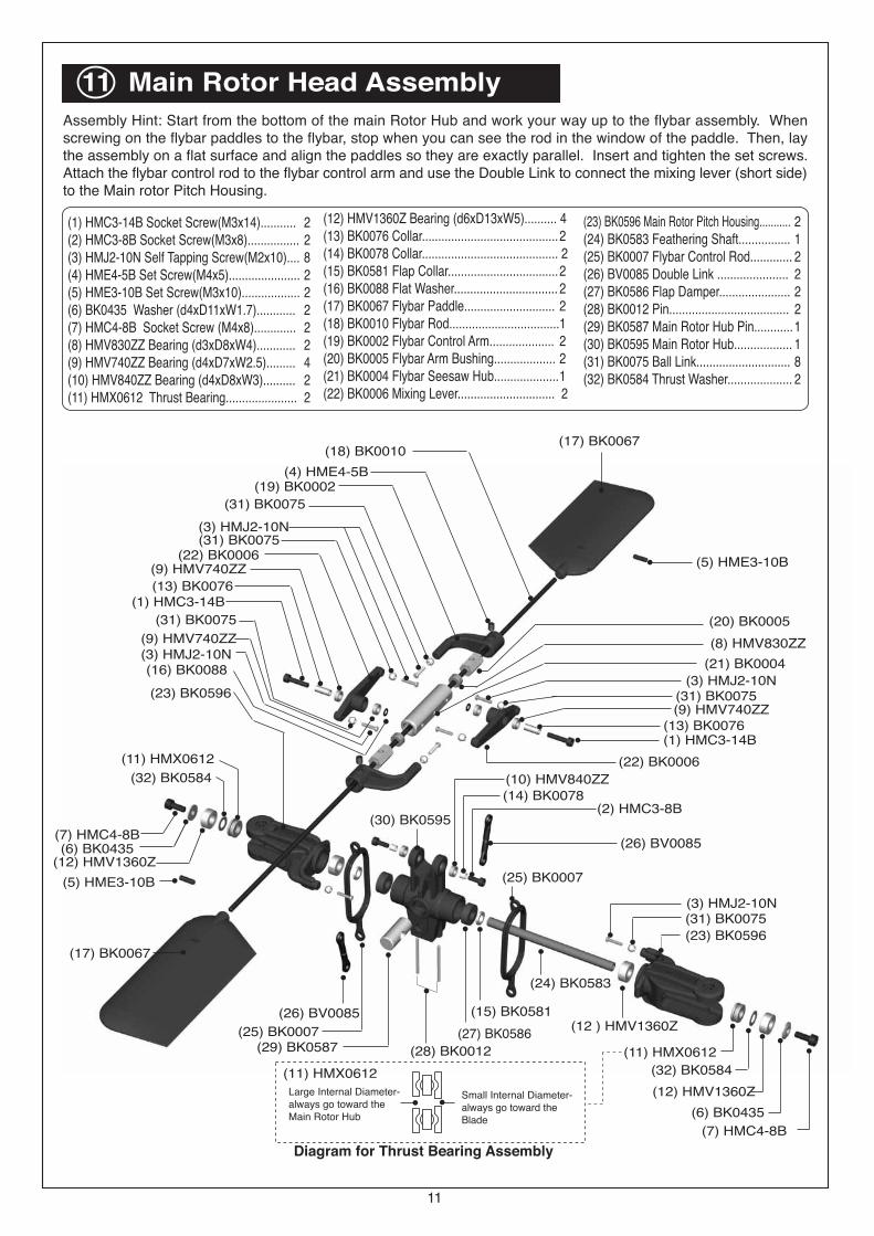
11 Main Rotor Head Assembly
(1) HMC3-14B Socket Screw(M3x14)........... 2(2) HMC3-8B Socket Screw(M3x8)................ 2(3) HMJ2-10N Self Tapping Screw(M2x10).... 8(4) HME4-5B Set Screw(M4x5)...................... 2(5) HME3-10B Set Screw(M3x10).................. 2(6) BK0435 Washer (d4xD11xW1.7)............ 2(7) HMC4-8B Socket Screw (M4x8)............. 2(8) HMV830ZZ Bearing (d3xD8xW4)............ 2(9) HMV740ZZ Bearing (d4xD7xW2.5)......... 4(10) HMV840ZZ Bearing (d4xD8xW3).......... 2(11) HMX0612 Thrust Bearing...................... 2
(12) HMV1360Z Bearing (d6xD13xW5).......... 4(13) BK0076 Collar..........................................2(14) BK0078 Collar.......................................... 2(15) BK0581 Flap Collar..................................2(16) BK0088 Flat Washer................................ 2(17) BK0067 Flybar Paddle............................ 2(18) BK0010 Flybar Rod..................................1(19) BK0002 Flybar Control Arm.................... 2(20) BK0005 Flybar Arm Bushing................... 2(21) BK0004 Flybar Seesaw Hub....................1(22) BK0006 Mixing Lever.............................. 2
(23) BK0596 Main Rotor Pitch Housing........... 2(24) BK0583 Feathering Shaft................ 1(25) BK0007 Flybar Control Rod............. 2(26) BV0085 Double Link ...................... 2(27) BK0586 Flap Damper...................... 2(28) BK0012 Pin..................................... 2(29) BK0587 Main Rotor Hub Pin............1(30) BK0595 Main Rotor Hub.................. 1(31) BK0075 Ball Link............................. 8(32) BK0584 Thrust Washer.................... 2
Assembly Hint: Start from the bottom of the main Rotor Hub and work your way up to the flybar assembly. Whenscrewing on the flybar paddles to the flybar, stop when you can see the rod in the window of the paddle. Then, laythe assembly on a flat surface and align the paddles so they are exactly parallel. Insert and tighten the set screws.Attach the flybar control rod to the flybar control arm and use the Double Link to connect the mixing lever (short side)to the Main rotor Pitch Housing.
Diagram for Thrust Bearing Assembly
(11) HMX0612
Large Internal Diameter-always go toward theMain Rotor Hub
Small Internal Diameter-always go toward theBlade
(5) HME3-18B
(6) HMM3Z
(8) HMV1050
(16) BK0302-1
(29) HMM26B
(3) HSE2-10B
(11) BK0082
(19) BK0026(20) BK0025
(9) HMV1060
(22) BK0028(23) BK0053
(18) BK0307
(6) HMM3Z(5) HME3-18B
(8) HMV1050
(29) HMM26B(13) BK0083
(28) BK0075
(4) HMF2-8N
(30) HME3-4B
(24) BK0050
(14) BK0414
(7) HMV1150X
(27) BK0047
(25) BK0051
(10) HMV740ZZ(28) BK0075(4) HMF2-8N
(12) BK0076
(1) HSE3-18B
(10) HMV740Z
(15) BK0088
(17) BK0303-1
(2) HMC2610B
(2) HMC2610B
(16) BK0303-1
(3) HME3-18B
(6) BK0626
(1) BK0616(5) BK0086
(5) BK0086
(2) HMM3Z
(6) BK0626(3) HME3-18B
(7) Main Rotor Head Ass'y.
12
12 Main Frame Assembly-Part5
(1) BK0616 Socket Screw(M3x20)..... 1
(2) HMM3Z Lock Nut(M3)........................1
(3) HME3-18B Set Screw(M3x18)........... 1
(4) BK0095 Linkage Rod......................... 2
(5) BK0086 Ball Link............................... 4
(6) BK0626 Canopy Retaining Post........ 2
(7) Main Rotor Head Assembly
Slide the main Rotor assembly over the main shaft and align the two pins toslide in the washout assembly. Make sure the holes in the main shaft line upwith the holes in the main rotor head. Insert the socket screw and secure withlocknut. Attach the ball linkage rods to the long end of the mixing lever andto the remaining inside linkage balls of the swash plate.
Assembly Tip: Work from left to right when assembling the parts. The tail pitchcontrol lever screws into the arm extending from the tail unit housing.
(1) HSE3-18B Self Tapping Screw(M3x18).1(2) HMC2610B Socket Screw(M2.6x10)........ 4(3) HSE2-10B Self Tapping Screw(M2x10).2(4) HMF2-8N Screw(M2x8).........................2(5) HME3-18B Set Screw(M3x18).............. 2(6) HMM3Z Lock Nut(M3)........................... 2(7) HMV1150X Bearing (d5xD11xW5)....... 1(8) HMV1050 Bearing (d3xD8xW4)........ 4(9) HMV1060 Bearing (d6xD10xW3)........ 2(10) HMV740ZZ Bearing (d4xD7xW2.5)... 2(11) BK0082 Collar(2x3x4)......................... 2(12) BK0076 Collar(3x4x10)....................... 1(13) BK0083 Pin(2x9)................................. 2(14) BK0414 Pin(2x12)............................... 1(15) BK0088 Flat Washer............................1(16) BK0302-1 Tail Pitch Housing (A)........ 2(17) BK0303-1 Tail Pitch Housing (B)........ 2(18) BK0307 Tail Rotor Hub....................... 1(19) BK0026 Tail Pitch Control Link........... 2(20) BK0025Tail Pitch Control Fork............ 1
(21) BK0027 Tail Pitch Control Slider.................. 1(22) BK0028 Tail Pitch Control Slide Bushing..... 1(23) BK0053 Tail Rotor Shaft.............................. 1(24) BK0050 Tail Pulley....................................... 1(25) BK0051 Tail Pulley Flange...........................1(26) BK0024 Tail Pitch Control Lever.................. 1(27) BK0047 Tail Unit Housing (R)...................... 1(28) BK0075 Link Ball......................................... 2(29) HMM26B Lock Nut(M2)................................4(30) HME3-4B Set Screw(M3x4)..........................1
13 Tail Unit Assembly
(4) BK0095
(4) BK0095
(26) BK0024
100mm
(21) BK0027
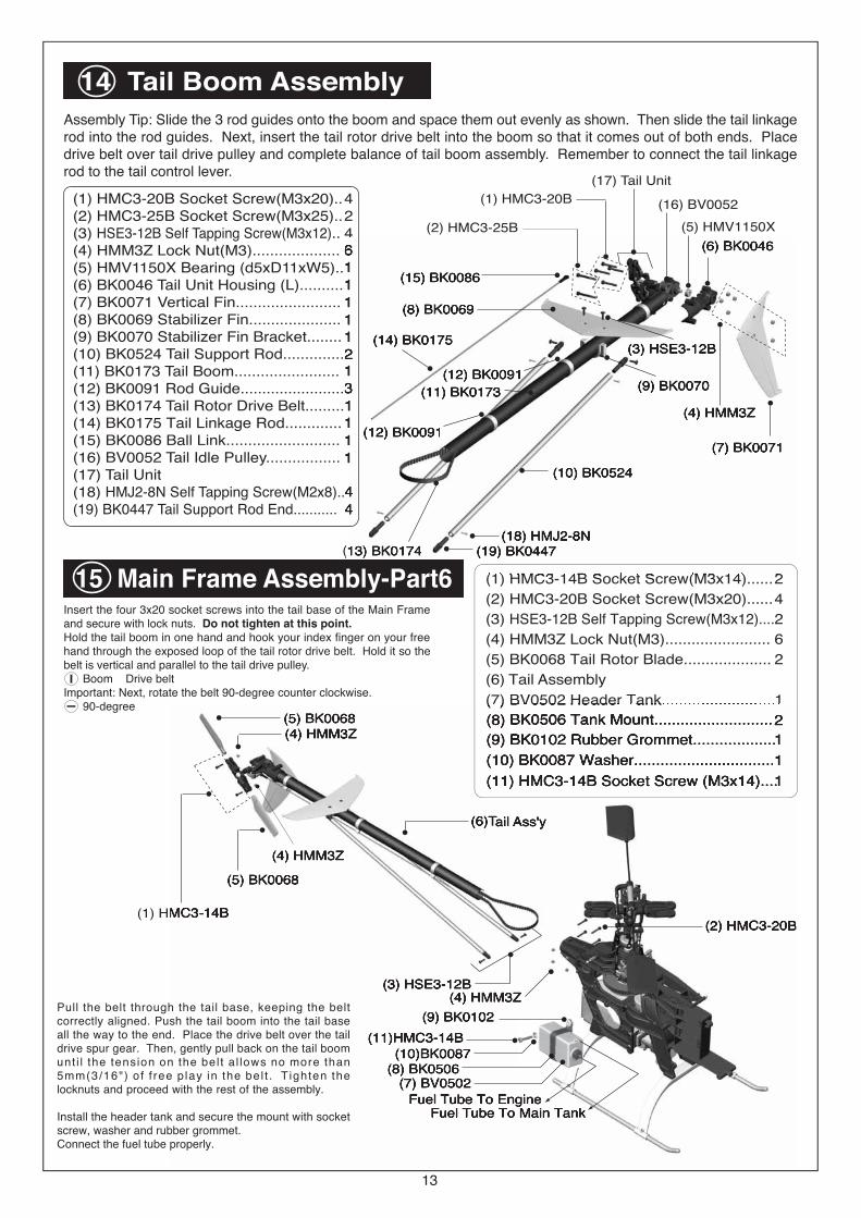
(7) BK0086
(6) BK0092
(3) HML2(4) BK0075
(2) HMF2-8N(4) BK0075
(3) HML2
(1) HSE2612N
(1) HSE2612N(2) HMF2-8N (4) BK0075
Pitch Servo
Throttle Servo
(3) HML2
(2) HMF2-8N
(7) BK0086
(5) BK0094
(1) HSE2612N
75mm
15
17 Servo Installation-Part2
51mm
(1) HSE2612N Self Tapping Screw(M2.6x12).... 8
(2) HMF2-8N Screw(M2x8)................................ 3
(3) HML2 Hex Nut(M2)...................................... 3
(4) BK0075 Linkage Ball.................................... 3
(5) BK0094 Linkage Rod .................................. 1
(6) BK0092 Linkage Rod .................................. 1
(7) BK0086 Ball Link.......................................... 4
On/Off Switch
Gyro Amplifier
Receiver
Battery Pack
(2) BK0106
(1) BE1052
Thunder Tiger TG-8000 piezogyro is recommended
(2) BK0106
(2) BK0106
(2) BK0106
On/Off Switch Face Plate
18 Receiver/Gyro Installation
(1) BE1052 Antenna Tube................... 1
(2) BK0106 Double Side Tape............ 2
Thunder Tiger recognizes that there are many brands of radios and gyros to choose from. You are encouraged toseek the advice of experienced helicopter pilots when making this decision.
Assembly Tip: Remove all the servo wheels prior to attaching the steellinkage balls. Make sure all linkages are the correct length.See Engine-Throttle Control Linkage on page 17.
Mount the Steel LinkBall at 10.5mm(approx7/16") from the centerof the servo horn forthe throttle arm.
16
19 Body/Canopy AssemblyCut off the bubble from the body leaving the lip all the wayaround. Neatness counts, so take your time. Next trim theflange from the canopy leaving a clean edge. You can lightlysand the edges to get it smooth and even. On the lip of theopening in the body, mark six points for drilling holes to securethe canopy: 1-in front, 1-in rear and 2 on each side.Using double stick tape secure canopy to body. Take a verysharp awl and make pilot holes through the canopy and bodylip. Make sure all holes line up. Remove double stick tapeand put in the self tapping screws. Install the body clip, decals,and rubber grommets.
(1) HMJ2-6B Self Tapping Screw(M2x4).. 6
(2) HSE3-12B Self Tapping Screw(M3x12).... 2
(3) BK0611 Body...................................... 1
(4) BK0102 Rubber Grommet ................. 2
(5) BK0098 Body Clip-A........................... 1
(6) BK0099 Body Clip-B........................... 1
(7) BK0612 Canopy.................................. 1
(8) JV0110 Decal......................................1
(4) BK0102
(4) BK0611
(2) HSE3-12B
(6) BK0099
(5) BK0098
(4) BK0102
(7) BK0612(1) HMJ2-6B
(1) HMJ2-6B
(1) HMJ2-6B(1) HMJ2-6B
20 Main Rotor AssemblyImportant-While Thunder Tiger takes great care to manufacture the most balanced blades available, no two rotorblades are exactly the same. It is highly recommended that you purchase a blade balancer from your hobby dealer.Follow the manufacturers instructions for balancing the blades and install on helicopter .
(1) BV0176 Main Rotor Blade..................2
(2) HMD2612B Self Tapping Screw (M2.6x12)....... 2
(3) BK0073 Upper Blade Grip................. 2
(4) BK0074 Lower Blade Grip................ 2
(5) HMM4Z Lock Nut(M4)...................... 2
(6) HMC4-27B Socket Screw.................. 2 (1) BV0176
(6) HMC4-27B
(5) HMM4Z
(2) HMD2612B
(3) BK0073
(4) BK0074
17
Mount the steel linkage ball to the outer hole on the metal throttle arm. At full throttle stick, the
carburetor hole should open completely. At low throttle and with the throttle trim all the way down,
the carburetor hole should close completely. Adjust the ATV function in your transmitter to achieve
the above requirement. Listen to the servo, it should not make any binding noise. Try keep the
throttle ATV between 90% and 110%. If your radio does not have ATV, then adjust the location
of the steel link ball on the throttle servo horn to get the correct throttle travel.
Engine Throttle Control Linkage
THROTTLE FULLY OPENTHROTTLE CLOSE
18
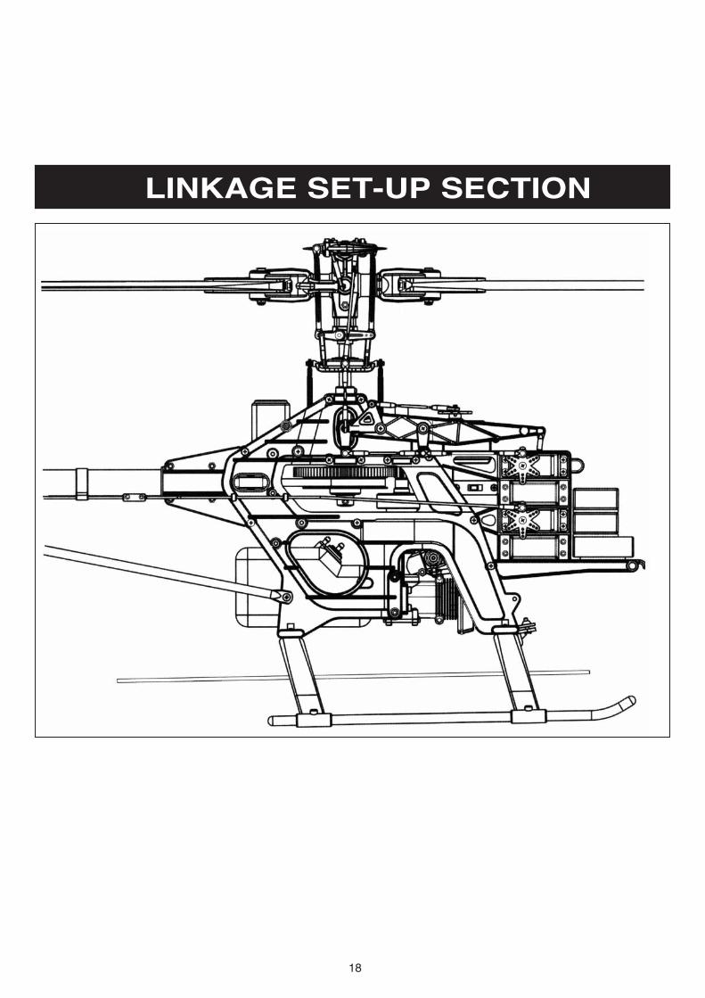
LINKAGE SET-UP SECTION
19
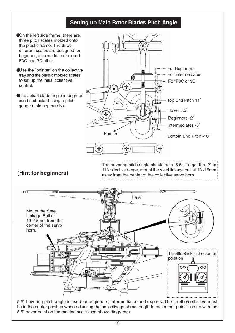
Setting up Main Rotor Blades Pitch Angle
For Beginners
For Intermediates
For F3C or 3D
Top End Pitch 11û
Hover 5.5ûBeginners -2ûIntermediates -5û
Bottom End Pitch -10ûPointer
Throttle Stick in the centerposition
Mount the SteelLinkage Ball at13~15mm from thecenter of the servohorn.
(Hint for beginners)The hovering pitch angle should be at 5.5û. To get the -2û to11ûcollective range, mount the steel linkage ball at 13~15mmaway from the center of the collective servo horn.
5.5û
5.5û hovering pitch angle is used for beginners, intermediates and experts. The throttle/collective mustbe in the center position when adjusting the collective pushrod length to make the "point" line up with the5.5û hover point on the molded scale (see above diagrams).
On the left side frame, there arethree pitch scales molded ontothe plastic frame. The threedifferent scales are designed forbeginner, intermediate or expertF3C and 3D pilots.
Use the "pointer" on the collectivetray and the plastic molded scalesto set up the initial collectivecontrol.
The actual blade angle in degreescan be checked using a pitchgauge (sold seperately).
�
�
�
20
�
�
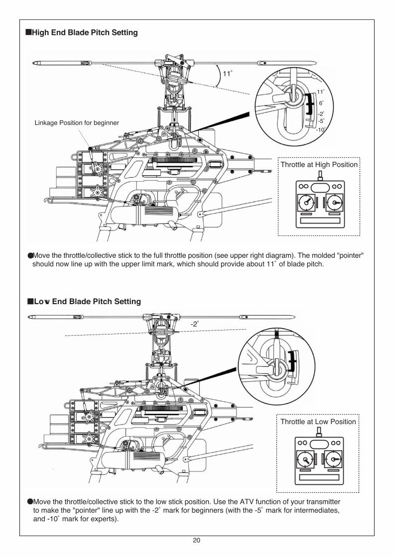
Throttle at High Position
Throttle at Low Position
High End Blade Pitch Setting
Low End Blade Pitch Setting
Linkage Position for beginner
11û
-2û
Move the throttle/collective stick to the low stick position. Use the ATV function of your transmitterto make the "pointer" line up with the -2û mark for beginners (with the -5û mark for intermediates,and -10û mark for experts).
Move the throttle/collective stick to the full throttle position (see upper right diagram). The molded "pointer"should now line up with the upper limit mark, which should provide about 11û of blade pitch.
11û
6û
-2û-5û
-10û
11û
-5û
21
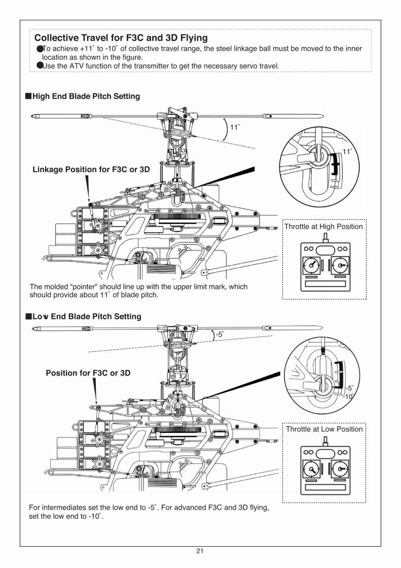
Collective Travel for F3C and 3D Flying
��
The molded "pointer" should line up with the upper limit mark, whichshould provide about 11û of blade pitch.
Throttle at High Position
Throttle at Low Position
High End Blade Pitch Setting
Low End Blade Pitch Setting
Linkage Position for F3C or 3D
Position for F3C or 3D
11û
For intermediates set the low end to -5û. For advanced F3C and 3D flying,set the low end to -10û.
-5û-10û
To achieve +11û to -10û of collective travel range, the steel linkage ball must be moved to the innerlocation as shown in the figure.Use the ATV function of the transmitter to get the necessary servo travel.
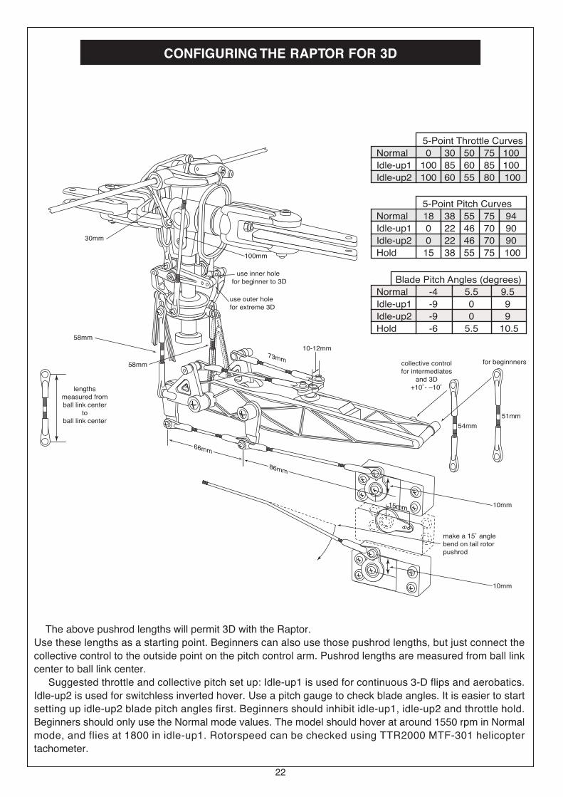
CONFIGURING THE RAPTOR FOR 3D
73mm73mm
66mm66mm
66mm86mm
make a 15û anglebend on tail rotorpushrod
collective controlfor intermediates
and 3D+10û- �10û
10-12mm
for beginnners
54mm
51mm
10mm
58mm
58mm
30mm
100mm
use outer holefor extreme 3D
use inner holefor beginner to 3D
15mm 10mm
5-Point Throttle Curves
Normal 0 30 50 75 100
Idle-up1 100 85 60 85 100
Idle-up2 100 60 55 80 100
5-Point Pitch Curves
Normal 18 38 55 75 94
Idle-up1 0 22 46 70 90
Idle-up2 0 22 46 70 90
Hold 15 38 55 75 100
Blade Pitch Angles (degrees)
Normal -4 5.5 9.5
Idle-up1 -9 0 9
Idle-up2 -9 0 9
Hold -6 5.5 10.5
lengthsmeasured fromball link center
toball link center
22
The above pushrod lengths will permit 3D with the Raptor.
Use these lengths as a starting point. Beginners can also use those pushrod lengths, but just connect the
collective control to the outside point on the pitch control arm. Pushrod lengths are measured from ball link
center to ball link center.
Suggested throttle and collective pitch set up: Idle-up1 is used for continuous 3-D flips and aerobatics.
Idle-up2 is used for switchless inverted hover. Use a pitch gauge to check blade angles. It is easier to start
setting up idle-up2 blade pitch angles first. Beginners should inhibit idle-up1, idle-up2 and throttle hold.
Beginners should only use the Normal mode values. The model should hover at around 1550 rpm in Normal
mode, and flies at 1800 in idle-up1. Rotorspeed can be checked using TTR2000 MTF-301 helicopter
tachometer.
23
Radio and Control Linkage Setup For Raptor 50
The performance of any RC helicopter and how well it flies depends strongly on how well the model has
been set up. We will go through step-by-step on how to set up the transmitter and mechanics linkages to
make your Raptor 50 fly at its best. Before you start, please set up the length of all the pushrods
according to the recommended lengths given in our 3D setup drawing in the instruction manual. The
pushrod lengths we have provided are valid for beginners to expert 3-D flying. Then, we recommend
using the reset function of your transmitter to reset all settings to factory default values. Check the end
point adjustment, or ATV value, on your transmitter to make sure the values are at 100%. Next we
recommend to program the numerical values we have provided in the table for the five points in the
throttle curves and for the collective pitch curves. Now you can proceed to do the mechanical
adjustments. We recommend to leave the transmitter on during the following adjustments.
1.Throttle Adjustment.The throttle arm on the carburetor should always be parallel to the throttle servo arm. When the throttle
barrel is half open, the throttle arm should be straight down. Leave it at this position. Turn on the
transmitter and leave the throttle in the Normal Throttle Mode. Set the throttle trim to the bottom and set
the throttle stick to the middle. Adjust the throttle pushrod to the correct length. Check the throttle servo
travel direction to confirm moving the throttle stick to the high position will move the throttle arm to the full
open position. Use a medium length servo arm. Pick a hole on the servo arm so that when the throttle
stick is moved to the highest or the lowest position, it will fully open or fully close the throttle arm, and
without binding. Now is the time to use the End Point Adjustment or ATV feature on the transmitter to fine
tune the throttle servo travel to achieve this. Avoid using too large or too small ATV values. The ATV
values should stay between 90% to 100%.
2.Collective Pitch SetupCollective control makes a helicopter ascend or descend by changing the main rotor blade angle.
Beginners and advanced fliers must attach the collective control pushrod to different locations on the
collective control arm. The difference is that advanced fliers desire more collective travel range, usually
+10 to �10 degrees of blade change range. Beginners only need �2 to +10 degrees of blade change
range. We assume you have programmed in our recommended values from the Table for the throttle and
pitch curves.
Collective Setup for Beginners:
Only the Normal Throttle Model will be used. We recommend using a collective pitch range of �2 to +10
degrees. Move the throttle/collective control stick to the center. Attach the servo arm so the servo arm is
in a horizontal position. The servo output shaft has a spline. Try mounting the servo arm with different
orientation until one of the arms becomes close to horizontal. Attach the steel ball to the collective servo
arm at about 15 mm from the center of the servo arm. Move the throttle stick to the middle position. Tilt
the collective control arm/tray assembly so it is approximately in the middle of its allowable mechanics
tilting range. Use the molded pitch scale on the left side of the plastic frame. The pointer on the collective
arm should point to the mark for the hover position. See our drawings of the molded scale in the other
section of this manual. Attach the pushrod. The pushrod length should be 51 mm as recommended in the
drawing. Use a pitch gauge to check the blade angle, it should be around 5.5 degrees. This is what you
need for hovering. This gives a hovering rpm around 1500.

24
Radio and Control Linkage Setup For Raptor 50
Move the throttle stick to the high position to check if it causes binding. Move the throttle stick to the low
position to check if it causes binding. The blade should be at 10 degrees at full collective control stick
setting, and -2 degrees at bottom stick position. Use the ATV or End Point Adjustment to eliminate
binding, or to make the pitch come out at +10 and -2 at the extremes.
Collective Setup for 3-D:
We recommend using a collective pitch range of approximately -10 to +10 degrees in the Stunt mode, or
idle-up mode. Use approximately -6 to +11 degrees in the Throttle Hold Mode. Please see the table of
pitch angle values we have provided for 3-D flying. To set up the collective for the 3-D or F3C flying, we
recommend starting with Idle-up Mode, or Stunt Mode. Increase the ATV or End Point Adjustment of the
collective channel to 130%. Attach the steel ball to the collective servo arm at about 15 mm from the
center of the servo arm. The pushrod should be around 54 mm long. Move the throttle stick to the center
position and mount the servo arm so the arm is in a horizontal position. Move the throttle stick to the high
position to check if it causes binding. Move the throttle stick to the low position to check if it causes
binding. The blade should be at 10 degrees at full collective control stick setting, and -10 degrees at
bottom stick position. Use the ATV or End Point Adjustment to eliminate binding, or to make the pitch
come out at +10 and -10 at the extremes.
After you have done the above and obtained the +10, 0 and -10 degree collective travel range in idle-up,
you will automatically get the proper collective settings for the Normal Throttle Mode and Throttle Hold
Mode. This is because you have programmed in the numerical values we have provided in the table.
If the throttle was set up according to described earlier, and the numerical values for the five points from
the table have been programmed into the transmitter, you will get the proper U-shaped throttle curve for
3-D flying. We have left the values for idle-up 1 and idle-up 2 the same. Individual fliers can refine the two
Idle-up settings to suit the need for different 3-D and F3C maneuvers. With Idle-up on, the main
rotorspeed should be around 1700 to 1800 for good 3-D flying. We recommend using only carbon
graphite main rotor blades for aggressive 3-D flying. Please try the Thunder Tiger 600 mm carbon
graphite rotor blades, they are designed for extreme 3-D flying with the Raptor 50. Wood main rotor
blades are fine for learning how to fly or for practicing simple maneuvers.
3. Cyclic Control SetupCyclic controls consist of fore/aft cyclic and left/right cyclic. Fore/aft cyclic is often called elevator control.
Left/right cyclic is often called aileron control. Elevator and aileron controls are terms used by airplane
pilots. Set the cyclic control stick of your transmitter in the middle and set the trims to the center. Put the
swashplate in a level position.
Fore/Aft Cyclic Setup: Attach the elevator servo arm to the elevator control servo. The servo arm should
point straight up. We recommend attaching the steel ball to the elevator servo arm at about 10 mm from
the center of the servo. Adjust the pushrod length from the elevator servo to make the swashplate level.
Left/Right Cyclic Setup: Attach the aileron servo arm to the aileron control servo. Mount the servo arm so
that the servo arm is close to perpendicular to the servo case. We recommand attaching a steel ball to the
elevator servo arm at about 10 to 12 mm from the center of the servo. Adjust the pushrod length from the
aileron servo to make the swashplate level. The two pushrods from the aileron servo to the aileron
bellcrank should be very similar in length.
25
Radio and Control Linkage Setup For Raptor 50
4. Tail Rotor Control and Gyro SetupThe radio setup for using a heading hold gyro and a non-heading hold gyro will be different. But the
mechanical setup will be the same.
Heading Hold Gyro Setup: Set the tail rotor mixing or revolution mixing values to zero for every throttle
mode in the transmitter. Leave the tail rotor stick in the center and move the tail rotor trim on the
transmitter to the center. Attach the servo arm so the arm is straight up. Mount the steel ball 10 to 12 mm
from the center of the servo arm. Attach the tail rotor pushrod rod. The pushrod will require a small 15
degree bent to give a smooth run. See the 3-D setup drawing. Adjust the pushrod rod ball links so the tail
rotor rotor blade angle is approximately 15 degree. Check the tail rotor control direction: a right tail rotor
command should increase the tail rotor blade pitch angle. A left command reduces the angle. Leave the
tail rotor control channel ATV at 100%. Use the hand and rotate the gyro to the left. This should cause the
servo to provide a right tail rotor command (increases the tail rotor blade pitch angle). Rotating the gyro to
the right should cause the servo to provide a left tail rotor command (reduces the tail rotor blade pitch
angle). If the gyro is providing the wrong feedback, then the gyro needs to be mounted upside down.
Some gyros have a reverse switch on the gyro box. Never use any tail rotor trim when using a heading
hold gyro, that causes the gyro to drift.
Non-Heading Hold Gyro Setup: Leave the throttle stick and tail rotor control stick in the center and move
the tail rotor trim on the transmitter to the center. Attach the servo arm so the arm is straight up. Mount the
steel ball 10 to 12 mm from the center of the servo arm. Attach the tail rotor pushrod rod. The pushrod will
require a small 15 degree bent to give a smooth run. See the 3-D setup drawing. Adjust the pushrod rod
ball links so the tail rotor rotor blade angle is approximately 15 degree. Check the tail rotor control
direction: a right tail rotor command should increase the tail rotor blade pitch angle. A left command
reduces the angle. Leave the tail rotor control channel ATV at 100%. Use the hand and rotate the gyro to
the left. This should cause the servo to provide a right tail rotor command (increases the tail rotor blade
pitch angle). Rotating the gyro to the right should cause the servo to provide a left tail rotor command
(reduces the tail rotor blade pitch angle). If the gyro is providing the wrong feedback, then the gyro needs
to be mounted upside down. Some gyros have a reverse switch on the gyro box. Go to the tail rotor
revolution mix function in the transmitter. Put in a numerical value of +25 for the high end revolution
mixing and -30 for the low end revolution mixing. Move the throttle stick to the high position and you
should see the tail rotor servo move and "increase" the tail rotor blade angle from 15 degrees to about 25
degrees. Move the throttle stick to the low position and you should see the tail rotor servo moves and
"decreases" the tail rotor blade angle from 15 degrees to 0 degrees. This is to compensage for the
change in torque on the helicopter fuselage when collective pitch is changed. A heading hold gyro does
not need tail rotor revolution mixing because it automatically senses heading changes and feed in
commands to lock on the helicopter heading. A non-heading hold gyro can only stabilize the rate that the
helicopters nose is rotating.
For 3-D flying with a non-heading hold gyro, it will be necessary to put in a V-shaped tail rotor mixing
curve. Try +15 for the high end revolution mixing and -15 for the low end revolution mixing.
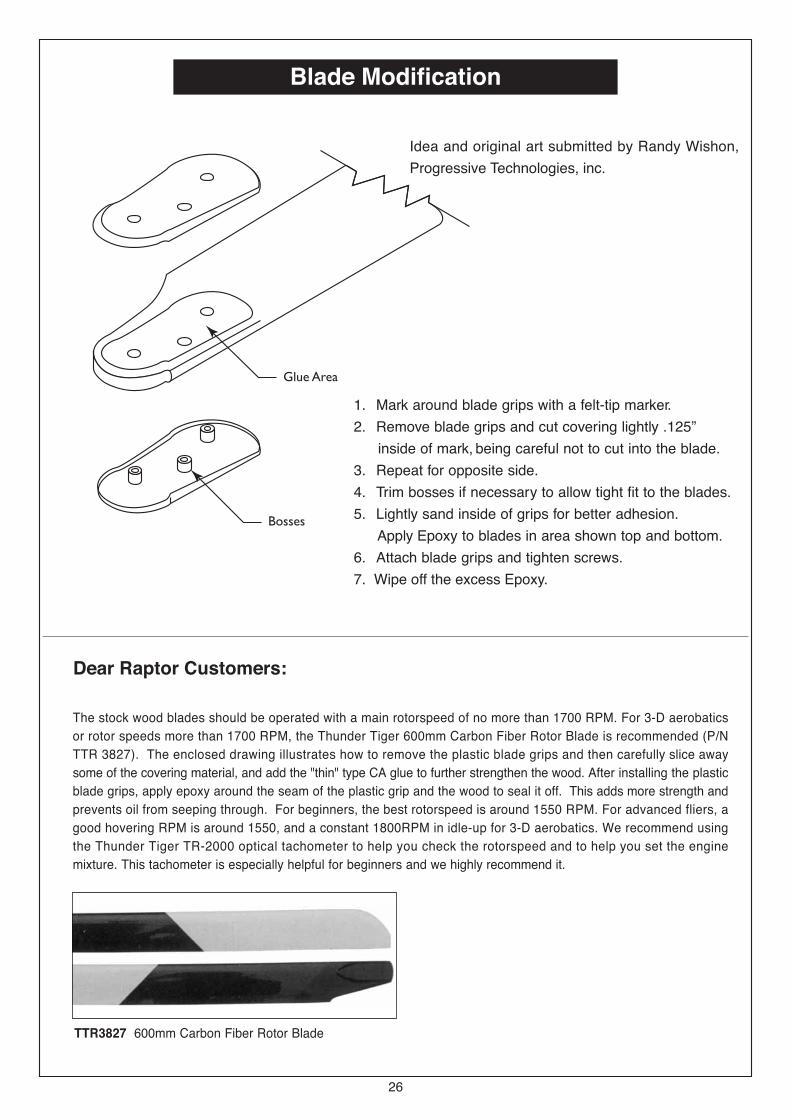
Blade Modification
1. Mark around blade grips with a felt-tip marker.
2. Remove blade grips and cut covering lightly .125�
inside of mark, being careful not to cut into the blade.
3. Repeat for opposite side.
4. Trim bosses if necessary to allow tight fit to the blades.
5. Lightly sand inside of grips for better adhesion.
Apply Epoxy to blades in area shown top and bottom.
6. Attach blade grips and tighten screws.
7. Wipe off the excess Epoxy.
Idea and original art submitted by Randy Wishon,
Progressive Technologies, inc.
Dear Raptor Customers:
26
The stock wood blades should be operated with a main rotorspeed of no more than 1700 RPM. For 3-D aerobatics
or rotor speeds more than 1700 RPM, the Thunder Tiger 600mm Carbon Fiber Rotor Blade is recommended (P/N
TTR 3827). The enclosed drawing illustrates how to remove the plastic blade grips and then carefully slice away
some of the covering material, and add the "thin" type CA glue to further strengthen the wood. After installing the plastic
blade grips, apply epoxy around the seam of the plastic grip and the wood to seal it off. This adds more strength and
prevents oil from seeping through. For beginners, the best rotorspeed is around 1550 RPM. For advanced fliers, a
good hovering RPM is around 1550, and a constant 1800RPM in idle-up for 3-D aerobatics. We recommend using
the Thunder Tiger TR-2000 optical tachometer to help you check the rotorspeed and to help you set the engine
mixture. This tachometer is especially helpful for beginners and we highly recommend it.
TTR3827 600mm Carbon Fiber Rotor Blade
27
After Flight Checklist
(1) Check every screw and bolt to make sure none has loosened due to vibration.
(2) Check every rotating and movable part to ensure they still move smoothly and
normally.
(3) Clean off the exhaust residue from the muffler, engine, and helicopter.
(4) Check all movable parts, such as gears, ball links, belt, etc. for unusual wear.
Trouble Shooting
[1]The engine will not start.* The engine starting shaft will not turn:The engine may be flooded with too much fuel. Please remove the glow plug first, then turn the enginewith the electric starter until the excess fuel spits out of the glow plug hole.
* The engine turns when the electric starter is appied, but the engine will not start:(1) Is the glow plug working? Remove the glow plug, does the platinum coil glow red when a 1.5 volt
battery is applied to the plug? If not, then the glow plug battery may be weak and old.(2) Is the carburetor needle properly set? Please refer to the engine instruction manual for proper
needle setting.(3) Does the throttle control arm move properly and in the correct direction according to your transmitter
command?
* Engine will start, but quits immediately.(1) Use the transmitter to increase the carburetor opening slightly. The throttle stick should never
exceed the 1/3 position when starting the engine.(2) Try a new or different type of glow pllug. There are different types of glow plugs on the market for
different types of fuel and operating conditions. Seek the advice of experienced fliers and alsoexperiment with different types of glow plugs until you find one that suits your operating conditionbest.
* Engine runs, but the helicopter will not lift off.(1) Check the main rotor blade pitch angle, it should be set at 5.5 to 6 degrees when the transmitter
throttle/collective stick is at the center position.(2) Does the engine throttle arm move properly? The carburetor opening should be fully open when the
transmitter throttle/collective stick is moved up. The carburetor opening should be completely closedwhen the transmitter throttle/collective stick is moved down and the throttle trim is also moved down.
(3) The carburetor needle is not set properly. Close the needle (turn it clockwise) all the way, then openthe needle (turn it counter clockwise) 1 and 1/2 turns and try again. If the model still will not lift, thenthe engine may be running too rich. If the symptom is the engine exhaust has a lot of smoke and theengine coughs and wants to quit when the transmitter throttle/collective stick is moved up, thenclose the needle 1/8 turn at a time, until the model will lift off. Do not turn the needle too far inward,that will make the engine run too lean and over-heat and damage the engine.
[2] Helicopter problems.* The helicopter shakes.(1) Is the blade spindle bent?(2) Is the flybar bent?(3) Is the main rotor shaft bent?(4) Are the two control paddles mounted at the same distance from the rotor shaft, are the paddles
parallel to each other, and in the proper direction?(5) Is the tail rotor shaft bent? The tail rotor blades mounted properly or damaged?(6) Are the main rotor blades damaged or mounted in the proper orientation? The blades may require
additional balancing. The blade balance can be checked by removing both blades and then use one ofthe 4 mm blade bolt and nut to hold the two blades together like a teeter totter. Then, hold the bladebold with your thumb and index finger. The two blades should teeter and remain in a level position. Ifnot, then add some tape to the lighter blade near the blade tip until the two blades teeter in a levelposition. Hobby shops also sell blade balancers that are designed solely for balancing modelhelicopter blades.
28
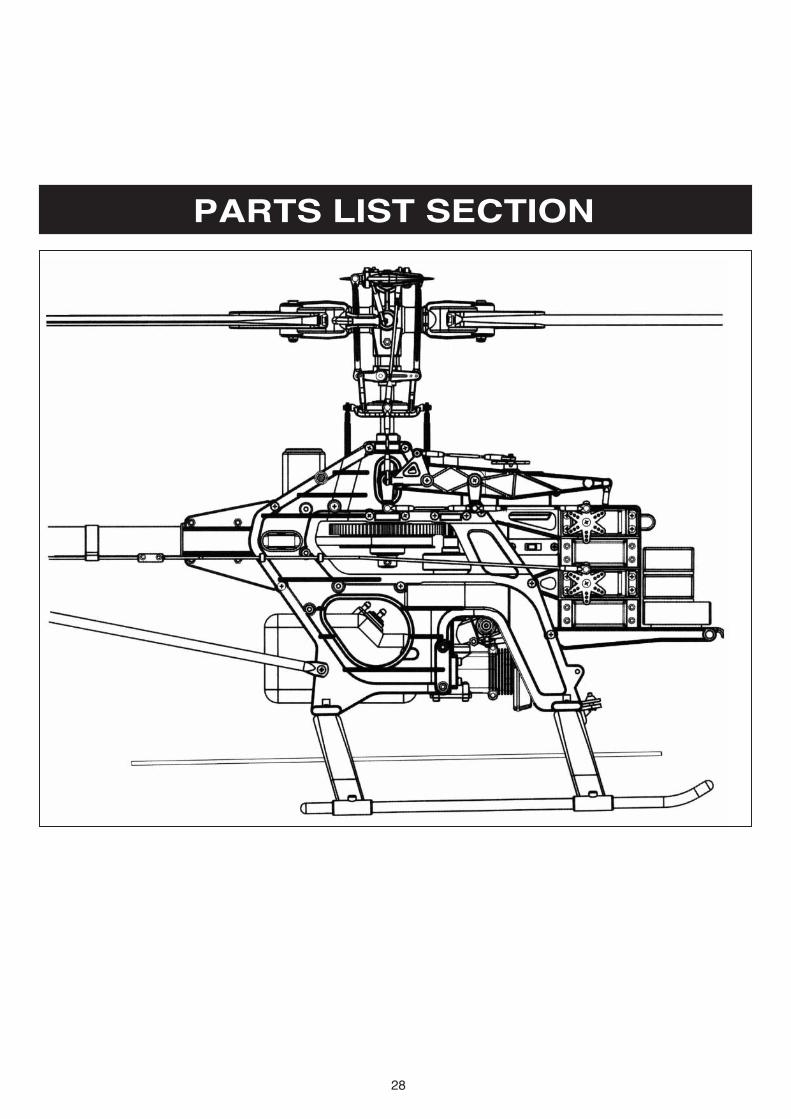
PARTS LIST SECTION
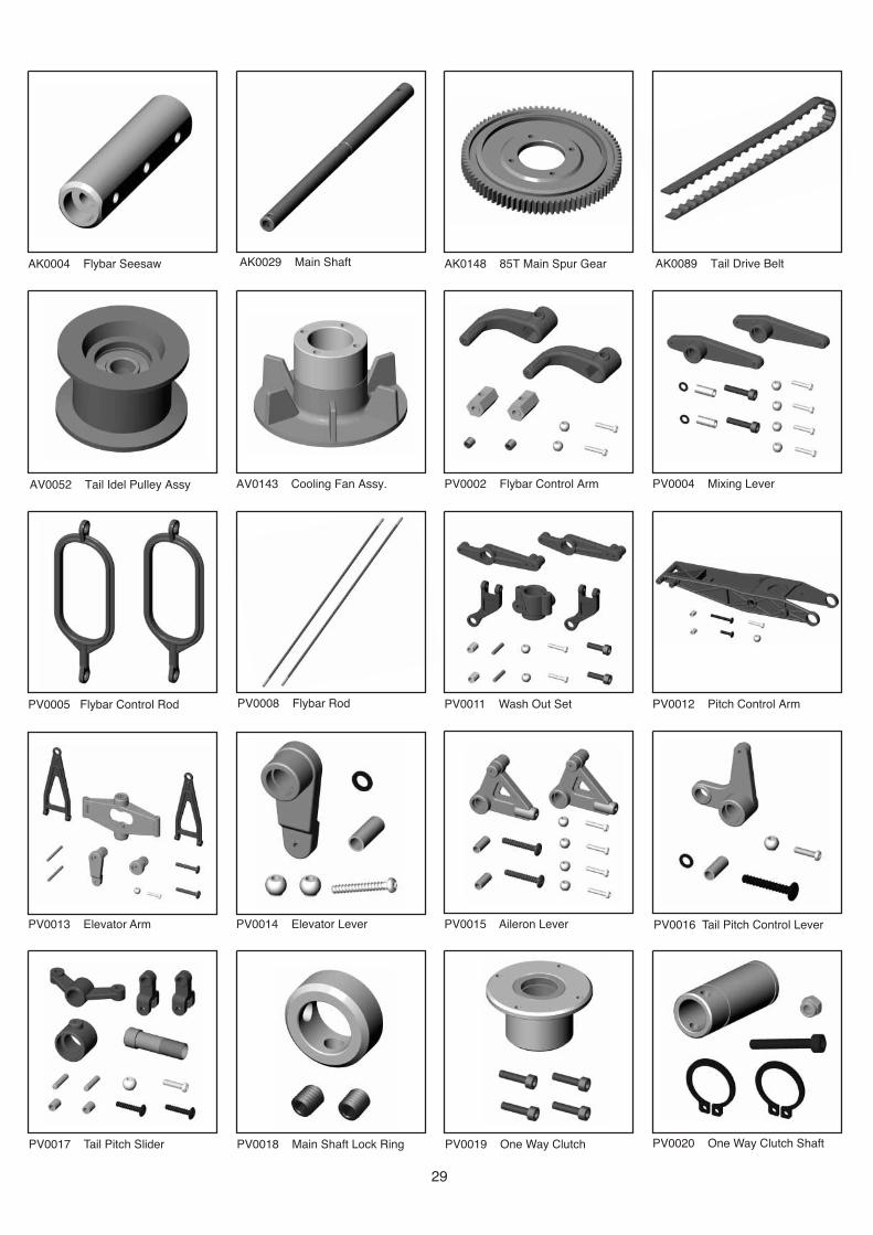
PV0013 Elevator Arm
AK0004 Flybar Seesaw AK0029 Main Shaft AK0148 85T Main Spur Gear
PV0004 Mixing Lever
PV0005 Flybar Control Rod
AV0143 Cooling Fan Assy. PV0002 Flybar Control Arm
PV0008 Flybar Rod PV0011 Wash Out Set PV0012 Pitch Control Arm
PV0014 Elevator Lever PV0015 Aileron Lever PV0016 Tail Pitch Control Lever
PV0017 Tail Pitch Slider PV0018 Main Shaft Lock Ring PV0019 One Way Clutch
AV0052 Tail Idel Pulley Assy
AK0089 Tail Drive Belt
PV0020 One Way Clutch Shaft
29
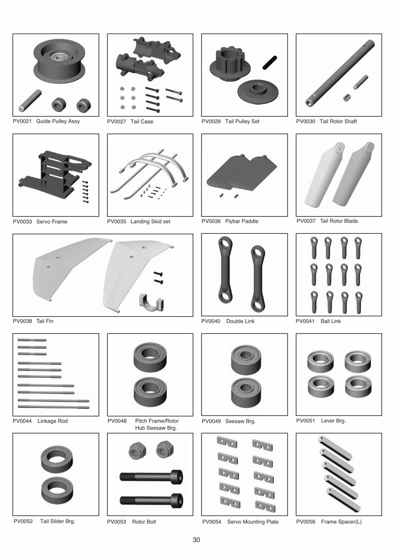
PV0051 Lever Brg.PV0048 Pitch Frame/Rotor
Hub Seesaw Brg.
PV0044 Linkage Rod
PV0041 Ball LinkPV0040 Double Link
PV0056 Frame Spacer(L)
PV0036 Flybar PaddlePV0035 Landing Skid setPV0033 Servo Frame
PV0030 Tail Rotor ShaftPV0029 Tail Pulley SetPV0021 Guide Pulley Assy
PV0038 Tail Fin
PV0037 Tail Rotor Blade
PV0027 Tail Case
PV0054 Servo Mounting PlatePV0053 Rotor Bolt
PV0049 Seesaw Brg.
PV0052 Tail Slider Brg.
30
PV0267 Loctite #242
(2) (1)
PV0093 Main Shaft Brg
HNI15HNI2HNI25HNI3
BK0109x2
BK0106x2
HNJ-1x3
PV0060 Installation Set
PV0062 Body Mount Rubber
PV0059 Tail Shaft Brg.PV0058 Linkage BallPV0057 Frame Spacer(S)
PV0092 Swashplate PV0107 Engine Mount (.50)
PV0109 High PerformanceMuffler (.46~.50)
PV0148 Tail Rotor Grip PV0118 Main Rotor Blades
PV0151 Tail Rotor Hub PV0203 Starter Shaft Brg.
PV0268 Loctite #262 PV0279 Tail Rod Guide PV0311 Header Tank
Grommets
PV0200 Tail Rotor Brg.
LOCTITE#262 GREASE
PV0270 Grease (For Bearing)
LOCTITE#242
31
PV0326 Carbon GraphiteBase Plate
PV0329 Tail Support PV0353 Main Rotor Grip PV0354 Main Rotor Hub
PV0355 Spindle PV0358 Clutch Bell PV0359 Clutch PV0360 Starter Shaft
PV0361 Starter Coupling PV0363 Fuel Tank PV0362 Main Frame Set
PV0364 Body PV0365 Thrust Brg. PV0368 Clutch Liner
PV0369 Canopy Only PV0372 Thrust Collar PV0373 Clutch Bell Brg.PV0370 Body Only
32
PV0374 Feathering Brg. PV0375 Body Retaining Set PV0379 Auto Rotation Pully PV0380 Pinion Gear 10T
PV0381 70 Durometer Flap Damper PV0392 Tail Control Rod PV0389 Decal
PV0393 R50 Tail Boom
HMF2-6N M2X6
HMF2-8N M2X8
HMJ2-10N M2X10
HMJ2-14N M2X14
HMJ2-6B M2X6
HMJ3-22B M3X22
HSE2-10B M2X10
HSE2612N M2.6X12
HSE3-12B M3X12
HSE3-18B M3X18
HSE3-5B M3X5
HMC3-10B M3X10
HMC3-12B M3X12
HMC3-14B M3X14
HMC3-20B M3X20
HMC3-25B M3X0.5L25
HMC3-32B M3X0.5XL32
HMC3-8B M3X8
HME3-10B M3X10
HME3-18B M3X18
HME3-5B M4X5
PV0088 Screw Bag (6pcs each) PV0089 Screw Bag (6pcs each)
BK0616 M3X20
33
NO. 3800 BLADE SUPPORT NO. 3801 6MM STARTEREXTENSION
NO. 3802 PRECISIONPITCH GAUGE
NO. 3803 REMOTE GLOWADAPTER
HELICOPTER ACCESSORIES
NO. 2000 TERA ON-BOARD DIGITATT LTATT CHOMETER
NO. 8000 TG-8000 GYRO
OPTIONAL PARTS
PV0068 ALUM COLL SERVO TRAY PV0095 STABILIZER CONTROLARM SET
PV0096 WASHOUT ASSEMBLY PV0097 ELEVATOR LEVER SET
PV0098 AILERON L-TYPE LEVER PV0100 CARBON FIBER TAIL SET PV0101 CARBON FIBER SKIDS PV0104 ALUMINIUM FRAMEPOST
PV0106 COOLING FAN (.50) PV0321 REAR MOUNTED TAILSERVO TRAY
PV329 CARBON TAIL BOOMBRACE
PV0338 METAL MAIN ROTOR HUB
PV0339 METAL MAIN ROTOR GRIP PV346 R50 REAR SERVO ROD PV0341 METAL TAIL PITCHSLIDER
34
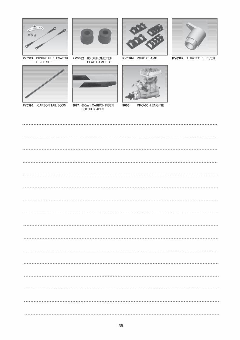
PV0349 PUSH/PULL ELEVATORLEVER SET
PV0382 80 DUROMETERFLAP DAMPER
PV0384 WIRE CLAMP PV0387 THROTTLE LEVER
35
PV0390 CARBON TAIL BOOM 3827 600mm CARBON FIBERROTOR BLADES
9605 PRO-50H ENGINE

36
Parts!No. Description Item!No. Description quantity ReferenceAssemble!Step
AK0004 Flybar Seesaw BK0004 Flybar Seesaw Hub 1 11
AK0029 Main Shaft BK0029 Main Shaft 1 9
AK0148 85T Main Spur Gear BK0148 85T Main Spur Gear 1 4
AK0174 Tail Drive Belt BK0174 Tail Drive Belt 1 14
AV0052 Tail Idel Pulley Assy. BV0052 Tail Idel Pulley 1 13
AV0143 Cooling Fan Assy. BV0143 Cooling Fan Assy. 1 8
PV0002 Flybar Arm BK0002 Flybar Control Arm 2 11
BK0005 Flybar Arm Bushing 2 11
BK0075 Linkage Ball 2 11
HME4-5B Set Screw, M4x5 2 11
HMJ2-10N Selftapping Screw, M2x10 2 11
PV0004 Mixing Lever BK0006 Mixing Lever 2 11
BK0075 Linkage Ball 4 11
BK0076 Collar (dxD4xL10) 2 11
BK0088 Flat Washer 2 11
HMC3-14B Socket Screw, M3x14 2 11
HMJ2-10N Selftapping Screw, M2x10 4 11
PV0005 Flybar Control Rod BK0007 Flybar Control Rod 2 11
PV0008 Flybar Rod BK0010 Flybar Rod 2 11
PV0011 Washout Set BK0014 Washout Base 1 5
BK0015 Flybar Control Lever 1 5
BK0016 Washout Linkage 2 5
BK0075 Link Ball 2 5
BK0077 Collar (d3xD4xL6) 2 5
BK0079 Pin 2 5
HMC3-10B Socket Screw, M2x10 2 5
HMJ2-10N Selftapping Screw, M2x10 2 5
PV0012 Pitch Control Arm BK0017 Pitch Control Arm 1 6
BK0075 Link Ball 1 6
BK0078 Collar (d3xD4xL4) 2 6
HMJ2-10N Selftapping Screw, M2x10 1 6
HMJ3-22B Selftapping Screw, M3x22 1 6
HSE3-12B Selftapping Screw, M3x12 1 6
PV0013 Elevator Arm BK0018 Elevator Control Arm 1 6
BK0019 Elevator Arm Parallel Lever 1 6
BK0020 Elevator Arm Shaft 1 6
BK0023 Elevator Arm Linkage 2 6
BK0075 Linkage Ball 1 6
BK0084 Pin (D2xL23) 2 6
HMJ2-10N Selftapping Screw, M2x10 1 6
HSE3-18B Selftapping Screw, M3x18 2 6
PV0014 Elevator Lever BK0021 Elevator Control Lever 1 6
BK0075 Linkage Ball 2 6
BK0076 Collar (d3xD4xL10) 1 6
BK0088 Flat Washer 1 6
HMJ2-14N Selftapping Screw, M2x14 1 6
PV0015 Aileron Lever BK0022 Aileron Control Lever 2 6
BK0075 Linkage Ball 4 6
BK0076 Collar (d3xD4xL10) 2 6
HMJ2-10N Selftapping Screw, M2x10 4 6
HSE3-18B Selftapping Screw, M3x18 2 6
PV0016 Tail Pitch Control Lever BK0024 Tail Pitch Control Lever 1 13
BK0075 Linkage Ball 1 13

37
Parts!No. Description Item!No. Description quantity ReferenceAssemble!Step
BK0076 Collar (d3xD4xL10) 1 13
BK0088 Flat Washer 1 13
HMJ2-8N Selftapping Screw, M2x8 1 13
HSE3-18B Selftapping Screw, M3x18 1 13
PV0017 Tail Pitch Slider BK0025 Tail Pitch Control Fork 1 13
BK0026 Tail Pitch Control Linkage 2 13
BK0027 Tail Pitch Control Slider 1 13
BK0028 Tail Pitch Control Slide Bushing 1 13
BK0075 Linkage Ball 1 13
BK0082 Collar, d2xD3xL4 2 13
BK0083 Pin, D2xL9 2 13
HMF2-8N Screw, M2x8 1 13
HSE2-10B Selftapping Screw, M2x10 2 13
PV0018 Main Shaft Lock Ring BK0030 Main Shaft Lock Ring 1 7
HME4-5B Set Screw, M4x5 2 7
PV0019 One Way Clutch BV0033 One Way Clutch Housing Set 1 4
HMV3-12 Socket Screw, M3x12 4 4
PV0020 One Way Clutch Shaft BK0034 One Way Clutch Shaft 1 4
HMC3-20B Socket Screw, M3x20 1 4
HMM3Z Lock Nut, M3 1 4
HMQ14 Retaining Ring, ∅14 2 4
PV0021 Guide Pulley Assy. BV0035 Guide Pulley 1 3
BK0036 Pulley Collar 2 3
BK0081 Pin, D13xL18 1 3
PV0027 Tail Case BK0046 Tail Unit Housing (L) 1 14
BK0047 Tail Unit Housing (R) 1 13
HMC3-20B Socket Screw, M3x20 4 14
HMC3-25B Socket Screw, M3x25 2 14
HMM3Z Lock Nut, M3 6 14
PV0029 Tail Pulley Set BK0050 Tail Pulley Set 1 13
BK0051 Tail Pulley Flange 1 13
BK0414 Pin, D2xL12 1 13
HME3-4B Set Screw, M3x4 1 13
PV0030 Tail Rotor Shaft BK0053 Tail Rotor Shaft 1 13
BK0414 Pin, D2xL12 1 13
HME3-4B Set Screw, M3x4 1 13
PV0033 Servo Frame BK0057 Servo Frame 1 3
HMJ3-12B Selftapping Screw, M3x12 6 3
PV0035 Landing Skid Set BK0064 Skid 2 10
BK0065 Skid Cap 4 10
BK0066 Skid Brace 2 10
HMJ3-18B Selftapping Screw, M3x18 4 10
HME4-5B Set Screw, M4x5 4 10
PV0036 Flybar Paddle BK0067 Flybar Paddle 2 11
HME3-10B Set Screw, M3x10 2 11
PV0037 Tail Rotor Blade BK0068 Tail Rotor Blade 2 15
PV0038 Tail Fin BK0069 Stabilizer Fin 1 14
BK0070 Stabilizer Fin Bracket 1 14
BK0071 Vertical Fin 1 14
HSE3-12B Selftapping Screw, M3x12 2 14
PV0040 Double Link BV0085 Double Link 2 11
PV0041 Ball Link BK0086 Ball Link 12 12
PV0044 Link Rod BK0092 LinkageRod (L=30) 3 17

38
Parts!No. Description Item!No. Description quantity ReferenceAssemble!Step
BK0093 Linkage Rod (L=45) 3 17
BK0094 Linkage Rod (L=60) 2 17
BK0095 Linkage Rod (L=76) 2 17
PV0048 Pitch Frame/
Rotor Hub Seesaw Brg.
HMV840ZZ Bearing, d4xD8xW3 2 6
PV0049 Seesaw Brg. HMV830ZZ Bearing, d4xD8xW4 2 11
PV0051 Leaver Brg. HMV740ZZ Bearing, d4xD7xW2.5 4 5
PV0052 Tail Slider Brg. HMV1060 Bearing, d6xD10xW3 2 13
PV0053 Rotor Bolt. HMC4-27B Cap Screw, M4x27 2 20
HMM4Z Lock Nut, M4 2 20
PV0054 Servo Mounting Plate BK0104 Servo Mounting Plate 10 16
PV0056 Frame Spacer (L) BK0058 Frame Spacer (L) 5 3
PV0057 Frame Spacer (S) BK0059 Frame Spacer (S) 10 3
PV0058 Link Ball BK0075 Linkage Ball 12 5
PV0059 Tail Shaft Brg. HMV1150 Bearing, d5xD11xW5 2 13
PV0060 Installation Set BE1052 Antenna Tube 1 18
BK0106 Double Side Tape 2 18
BK0109 Rubber Band 5x3 20xT1 2 18
HNI15 Hex Wrench 1.5mm 1 1
HNI2 Hex Wrench 2mm 1 1
HNI25 Hex Wrench 2.5mm 1 1
HNI3 Hex Wrench 3mm 1 1
HNJ-1 Tie Band 2.5x100 3 8
PV0062 Body Mount Rubber Grommet BK0102 Body Mount Rubber 5 19
PV0092 Swash Plate BV0092 Metal Swash Plate 1 7
PV0093 Main Shaft Bearing HMV1680 Bearing, d8xD16xW5 1 2
HMV6800 Bearing, d10xD19xW5 2 6
PV0107 Engine Mount (.50) BK0087 Washer 4 9
BK0144 Engine Mount 1 9
BK0179 Engine Mount Spacer 2 9
HMC3-14 Socket Screw 8 9
PV0109 High Performance BA1579 Muffler Gasket 1 9
Muffler (.46-.50) MV0172 Muffler 1 9
HMC3-35B Socket Screw 2 9
HMT3B Spring Washer 2 9
PV0118 Main Rotor Blades BV0176 Main Rotor Blade 1 20
PV0148 Tail Rotor Grip BK0302-1 Tail Pitch Housing (A) 2 13
BK0303-1 Tail Pitch Housing (B) 2 13
HMC2610B Socket Screw, M2.6x10 4 13
HMM26B Lock Nut, M2.6 4 13
HMC3-14B Socket Screw, M3x14 2 13
HMM3B Lock Nut, M3 2 13
PV0151 Tail Rotor Hub BK0307 Tail Rotor Hub 1 13
HME3-18B Set Screw, M3x18 2 13
HMM3B Lock Nut, M3 2 13
PV0200 Tail Rotor Brg. HMV1050 Bearing, d5xD10xW5 4 13
PV0203 Starter Shaft Brg. HMV696Z Bearing, d6xD15xW5 2 3
PV0267 Loctite #242 1
PV0268 Loctite #262 1
PV0270 Plastic Gear Grease 1
PV0279 Tail Rod Guide BK0091 Rod Guide 3 14
PV0311 Header Tank BK0087 Washer 1 15
BK0102 Rubber Grommet 1 15

39
Parts!No. Description Item!No. Description quantity ReferenceAssemble!Step
BK0506 Header Tank Support 1 15
BK0502 Header Tank 1 15
HMC3-14B Socket Screw 1 15
PV0326 Carbon Graphite Base Plate BK0525 Carbon Graphite Base Plate 1 10
PV0329 Tail Support BK0447 Tail Support Rod End 4 14
BK0524 Tail Support Rod 2 14
HMJ2-8N Selftapping Screw, M2x8 4 14
PV0353 Main Rotor Grip BK0075 Linkage Ball 2 11
BK0596 Main Pitch Housing 2 11
HMJ2-10N Selftapping Screw, M2x10 2 11
PV0354 Main Rotor Hub BK0587 Main Rotor Pin 1 11
BK0616 Socket Screw, M3x20 1 12
BV0595 Main Rotor Hub 1 11
HMM3Z Lock Nut, M3 1 12
PV0355 Spindle BK0581 Flap Collar 2 11
BK0583 Feathering Shaft 1 11
BK0435 Washer, d4xD11x1.7 2 11
HMC4-8B Socket Screw, M4x8 2 11
PV0358 Clutch Bell BV0591 Clutch Bell Set 1 2
PV0359 Clutch BK0170 Shim 1 8
BV0589 Clutch Bell Set 1 8
HMC3-10B Socket Screw, M3x10 2 8
PV0360 Starter Shaft BK0592 Starter Shaft 1 3
HME4-5B Set Screw, M4x5 2 3
HMS5 E-Clip 1 3
PV0361 Starter Coupling BK0594 Starter Coupling 1 3
HME4-5B Set Screw, M4x5 2 3
PV0362 Main Frame Set BK0058 Frame Spacer (L) 4 3
BK0059 Frame Spacer (S) 8 3
BK0599 Main Frame Left Side 1 3
BK0600 Main Frame Right Side 1 3
HMC3-20B Socket Screw, M3x20 4 15
HMM3Z Lock Nut, M3 4 15
HSE3-12B Selftapping Screw, M3x12 24 3
PV0363 Fuel Tank BV0605 Fuel Tank Set 1 1
PV0364 Body BK0098 Body Clip A 1 19
BK0099 Body Clip B 1 19
BK0102 Rubber Grommet 2 19
BK0611 Body 1 19
BK0612 Canopy 1 19
HSE3-12B Selftapping Screw, M3x12 2 19
PV0365 Thrust Brg. HMX0612 Thrust Bearing 2 11
PV0368 Clutch Liner BK0590 Clutch Liner 2 2
PV0369 Canopy Only BK0612 Canopy 1 19
HMJ2-6B Selftapping Screw, M2x6 6 19
PV0370 Body Only BK0098 Body Clip A 1 19
BK0099 Body Clip A 1 19
BK0611 Body 1 19
BK0102 Rubber Grommet 2 19
HSE3-12B Selftapping Screw, M3x12 2 19
PV0372 Thrust Collar BK0584 Thrust Collar 2 11
PV0373 Clutch Bell Brg. HMV1260Y Bearing, d6xD12xW4 2 2
PV0374 Feathering Brg. HMV1260Z Bearing, d6xD13xW5 2 11

40
Parts!No. Description Item!No. Description quantity ReferenceAssemble!Step
PV0375 Body Retaining Set BK0626 Body Mount Nut 2 19
HME3-18B M3x18 Set Screw 2 19
PV0379 Auto Rotation Pully BK0610 Auto Rotation Pully 1 4
HMC3-8B Socket Screw 4 4
PV0380 Pinion Gear (10T) BK0624 Drive Gear 1 2
PV0389 Decal JV0110 Decal 1 19
PV0392 Tail Control Rod BK0086 Ball Link 2 14
BK0105 Tail Control Rod Joint 1 16
BK100-1 Push Pull Rod-1 1 16
BK0175 Push Pull Rod-2 1 14
HME4-5B Set Screw, M4x5 2 14
PV0393 R50 Tail Boom BK0173 Tail Boom 1 14
PV0088 Screw Bag HMF2-6N Screw, M2x6 6
HMF2-8N Screw, M2x8 6
HMJ2-10N Selftapping Screw, M2x10 6
HMJ2-14N Selftapping Screw, M2x14 6
HMJ2-6B Selftapping Screw, M2x6 6
HMJ3-22B Selftapping Screw, M3x22 6
HSE2-10B Selftapping Screw, M2x10 6
HSE2612N Selftapping Screw, M2.6x12 6
HSE3-12B Selftapping Screw, M3x12 6
HSE3-18B Selftapping Screw, M3x18 6
HSE3-5B Selftapping Screw, M3x5 6
PV0089 Screw Bag BK0616 Socket Screw, M3x20 2
HMC3-10B Socket Screw, M3x10 6
HMC3-12B Socket Screw, M3x12 6
HMC3-14B Socket Screw, M3x14 6
HMC3-20B Socket Screw, M3x20 6
HMC3-25B Socket Screw, M3x25 6
HMC3-32B Socket Screw, M3x32 6
HMC3-8B Socket Screw, M3x8 6
HME3-10B Set Screw, M3x10 6
HME3-18B Set Screw, M3x18 6
HME4-5B Set Screw, M4x5 6