assembly, application and maintenance manual
TRANSCRIPT

www.akisasansor.com.tr
1
ASSEMBLY, APPLICATION and MAINTENANCE MANUAL
3.Organize Sanayi Bölgesi Kayacık Mahallesi
T.Ziyaeddin Caddesi 6. Sokak No:2
KONYA/TÜRKİYE
Tel: 0 332 239 07 29 (pbx)
Fax: 0 332 239 07 59
www.akisasansor.com.tr

www.akisasansor.com.tr
2
INDEX
INDEX ...................................................................................................................................................................................... 2
FIGURES LIST ......................................................................................................................................................................... 3
TABLES LIST .......................................................................................................................................................................... 3
AIM ........................................................................................................................................................................................... 4
WARNING ............................................................................................................................................................................... 4
1. COMPANY PROFILE ......................................................................................................................................................... 5
1.1. INTRODUCTION ............................................................................................................................................................... 5
1.2. COPY RIGHT .................................................................................................................................................................... 5
1.3. BASICS . ............................................................................................................................................................................. 6
1.4. GENERAL ATTENTION . ................................................................................................................................................. 6
2. TRANSPORTION . ............................................................................................................................................................. 6
3. STORAGE . ......................................................................................................................................................................... 9
4. WARNING ......................................................................................................................................................................... 9
5. ASSEMBLING ................................................................................................................................................................ 10
5.1. ASSEMBLIG ON GROUND ............................................................................................................................................ 10
5.2. MOTOR ELECTRICITY CONNECTION ..................................................................................................................... 10
6. ENCODER ASSEMBLING ............................................................................................................................................. 10
6.1. ENCODER MOUNTING PROCESS ............................................................................................................................. 10
6.2. ENCODER DISMOUNTING PROCESS ....................................................................................................................... 11
6.3. ENCODER CONNECTION SCHEMAS ........................................................................................................................ 12
6.3.1. ENCODER COLOR CODES ....................................................................................................................................... 12
6.3.2. ARKEL ADRIVE (ECN 1313 / ECN 113) .................................................................................................................. 13
6.3.3. FUJI FRENIC LIFT (ECN 1313 / ECN 113) ............................................................................................................... 13
6.3.4. FUJI FRENIC LIFT (ECN 1387 SIN-COS) ................................................................................................................. 14
6.3.5. OMRON YASKAWA (ECN 1313 / ECN 113) ........................................................................................................... 14
7. BRAKE SETTING PROCEDURE .................................................................................................................................. 15
7.1. AIR GAP TOLERANCE ................................................................................................................................................ 15
7.2. AIR GAAP CONTROL and SETTING ......................................................................................................................... 15
7.3. BRAKE AIR GAP CONTROL ....................................................................................................................................... 15
7.4. AIR GAP SETTING ...................................................................................................................................................... 15
7.5. BRAKE ACT CHECKING ............................................................................................................................................. 16
8. MICRO – SWITCHS CONTROL SETTING ................................................................................................................. 16
8.1 USING……………………………………………………………………………………………………………………. 17
9. MAINTENANCE ............................................................................................................................................................ 17
9.1. A MONTH AFTER ASSEMBLING …………………………………………………………………………………… 17
9.2. EVERY YEAR ………………………………………………………………………………………………………….17

www.akisasansor.com.tr
3
10. MACHINE and PARTS GENERAL INTRODUCTION ............................................................................................... 18
10.1. AK TYPE MACJINES GENERAL INTRODUCTION ............................................................................................... 18
10.2 AKIS GEARLESS ELEVATOR MACHINES BRAKE EQUIPMENT CHANGING INSTRUCTIONS …………..... 19
11. MACHINES SIZE and TECHNICAL FEATURES ……………………………………………………………………. 23
12. ERROR RECOVERY ......................................................................................... ............................................................ 36
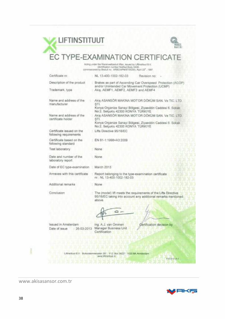
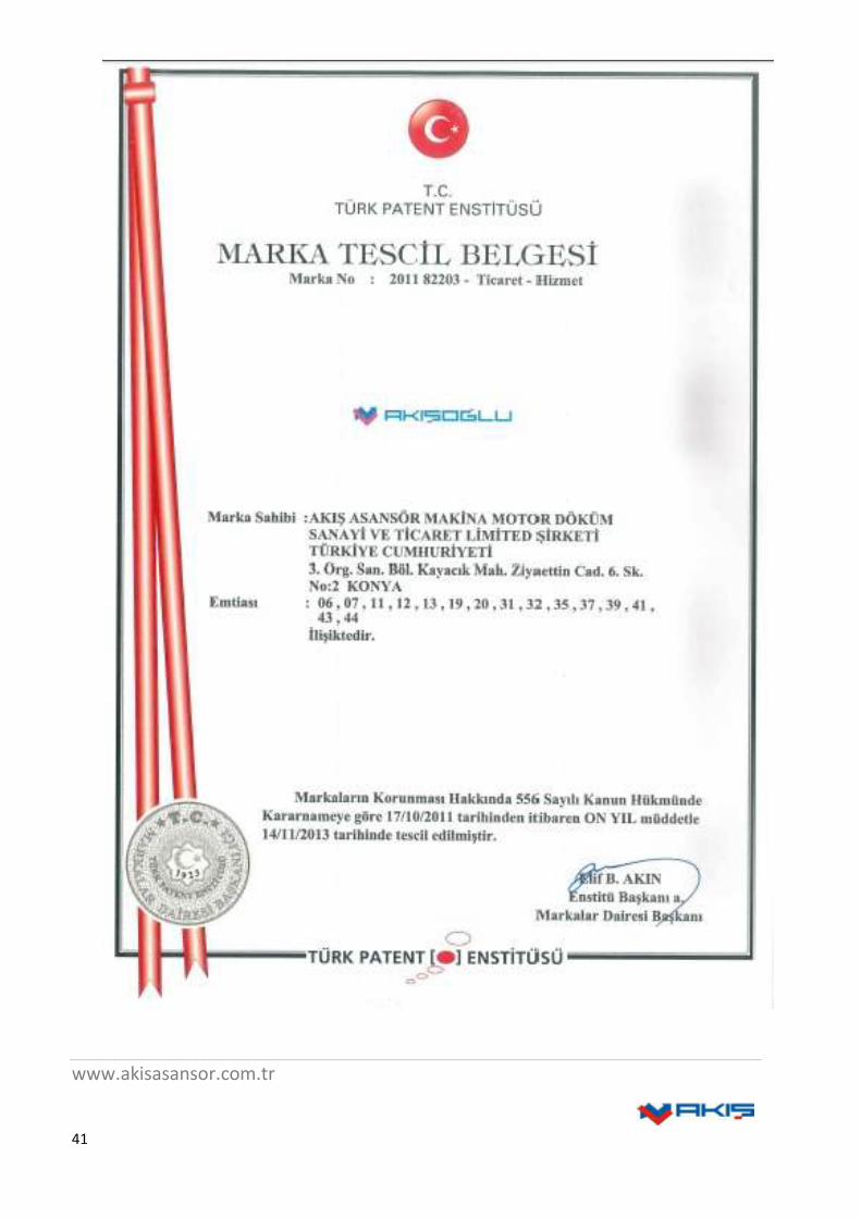
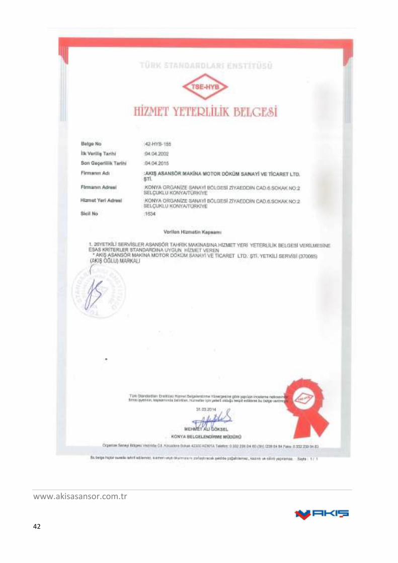
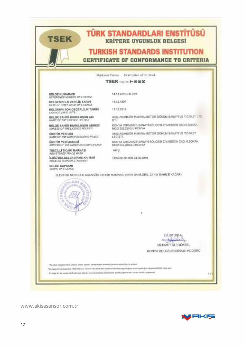
10. QUALITY and CONFORMITY CERTIFICATES …………………………………………………………………. 37-54
FIGURES LIST
FIGURE 1. AK MACHINE and MOTORS TRANSPORT ...................................................................................................... 7
FIGURE 2. ENCODER MOUNTING PROCESS .................................................................................................................. 11
FIGURE 3. ENCODER DISMOUNTING PROCESS ............................................................................................................ 12
FIGURE 4. ARKEL ADRIVE CONNECTION SCHEMA .................................................................................................... 13
FIGURE 5. FUJI FRENIC LIFT CONNECTION SCHEMA ................................................................................................. 13
FIGURE 6. FUJI FRENIC LIFT CONNECTION SCHEMA ................................................................................................. 14
FIGURE 7. OMRON YASKAWA CONNECTION SCHEMA ............................................................................................. 14
FIGURE 8. AK TYPE MACHINES EXPLOTED VIEW ....................................................................................................... 22
FIGURE 9. BUSHED DEFLECTION PULLEY .................................................................................................................... 23
FIGURE 10. DEFLECTION PULLEY WITH BALL BEARING .......................................................................................... 23
AK TYPE ELEVATOR MACHINES SIZE and TECHNICAL FEATURES .................................................................. 23-35
TABLES LIST
TABLE 1. MACHINE MOTOR WEIGHT TABLE ................................................................................................................. 8
TABLE 2. DEFLECTION PULLEY WEIGHT TABLE .......................................................................................................... 9
TABLE 3. ENCODER CABLE COLOR ................................................................................................................................ 12
TABLE 4. Brake Data ……………………………………………………………………………………………………..… 16
TABLE 4. AK TYPE ELEVATOR MACHINE PARTS ....................................................................................................... 22
ELEVATOR MACHINE SIZE and TECHNICAL FEATURES ........................................................................................ 24-35
ERROR RECOVERY ............................................................................................................................................................ 36
www.akisasansor.com.tr
4
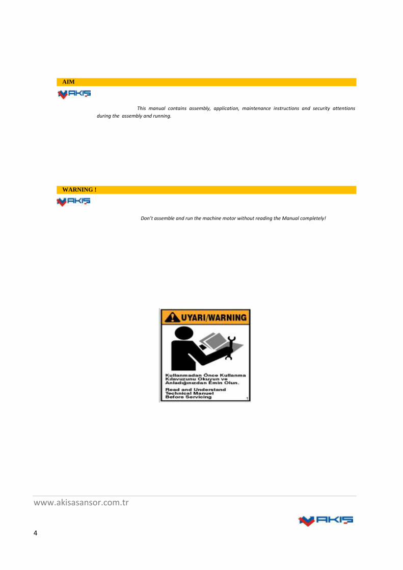
AIM
This manual contains assembly, application, maintenance instructions and security attentions
during the assembly and running.
WARNING !
Don’t assemble and run the machine motor without reading the Manual completely!
www.akisasansor.com.tr
5
1. COMPANY PROFILE
Akis, founded in 1978, has began manufacturing elevator machines and motors as integrated production by means
of gained experience and knowledge during the period with its new investments.. Akis has become one of the most important
company in our country and also in elevator sector in worldwide due to continuous investment policy into its technology.
It carries out its activities in its modern and integrated production facilities in total 100.000 m2 area with 45.000
m2closed area in Konya Organized Industrial Zone.
Akis realizes production elevator machine and motors in the international standards in the biggest and modern
foundry facility in Europe, machining department equipped with high technology and high quality control laboratory.
Akis gives great importance to research and development activities with cooperation between R&D department and
university. In this context, it constantly increases its product range. It started serial production of gearless elevator motors
after complete gearless motor project which it run together with TUBİTAK.
It gives great importance to quality and safety during each production phase. It studies and analysis each part which
is utilized to produce elevator machine motors in its laboratory. Akis has domestic and international certificates such as ISO
9001:2008, GOST, CE, TÜV SÜD, TSEK and etc.
In 2007, as a result of its cooperation agreement with Siemens Akis started production of Control Panel Board with
Frequency Control. It keeps producing control panels as a unique partner of Siemens.
Akis is the biggest manufacturer of Turkey and the region with its monthly production capacity and it meets
requirement of elevator machine and motor in Turkey.
1.1 Introductıon
This manual covers introduction, assembling, maintenance and repair instructions for AKIŞ brand magnetic
synchronic gearless motor models such as AK1, AK2, AK3, AK4, AK5, AK6 . The instructions that into manual ,
have to be applied completely.
All personel who will use the motor, must carefully read, , understand and apply the information into manual. In
case of damages because of any act at out of this manual instructions, AKIŞ COMPANY is not responsible.
1.2 Copyright
AKIŞ COMPANY is COPYRIGHT holder of this manual. In case of quotation or copying of this manual partially
or completely without permission, legal sanctions will be applied concerned people or companies.

www.akisasansor.com.tr
6
1.3 Basics
AKIŞ AK type magnetic gearless machines are composed of synchronic motor, driving pulley, side bearing,
encoder and magnetic brake system.
It is 40% more effective than asynchronic motor machines. Thereby, it great benefits to user together with obtained
energy saving, is long life as a result of to be gearless. And also, it great benefits for costs of environmental pollution, fire
danger during using due to be motor oil free. V3F control makes the machine very silent and comfortable , and also low
motor speed increases of system safety maximal.
Through its compact constitution, no need machine house and so much space. It can easily be integrated to every kind of
building. It avoids vibration through regular period on speed changing. Through fine control system, it has sensitive stopping
and moving capability.
1.4 General Attention
Our motors have been running with the power values which written on them, if their temperature values are
between 0°C-40°C. In case of exceeding of these temperature values, please contact us or realize external applications that
obtaining permanent atmosphere temperature.
The maximum speed that shown on the motor label, is composed of motor speed number and pulley diameter.
Motor has been designed as workable at 40% occupancy rate and 240 s/h.
2. TRANSPORTATION
Please control general outlook of the machine during delivery. If it is damaged, please notify us its serial number.
A wedge is available under the machine to transport easily.
Please dismount this wedge during the montage and then mount it.
The machine transport has to be realized in safe. During the machine loading and putting down, has to be very
careful against to knocking, vibration, and descending.
The machine has to be loaded and put down slowly.
Due to level difference between machine and driving pulley, be careful that the driving pulley must not be lied
down and touch ground roughly. This may cause curving of machine axis and bolt detaching.
During putting down, the machine has to put down as fastened with hawser to crooks which are above the machine
IN EVERY PHASE OF THE MACHINE FASTENING TO
CROOKS, LIFTING,REPLACEMENT , TO BE CAREFULL AND
ATTENTION IS VITALLY IMPORTANT.

www.akisasansor.com.tr
7
In this chapter, the technics and important points that used lifting the machines which manufactured by AKIŞ, are displayed.
The customer is responsible of steel hawsers, chains, belts, crooks, cranes conformity, that will be used for those all
operations.
Figure 1. AK Machine and Motor Transportation
www.akisasansor.com.tr
8
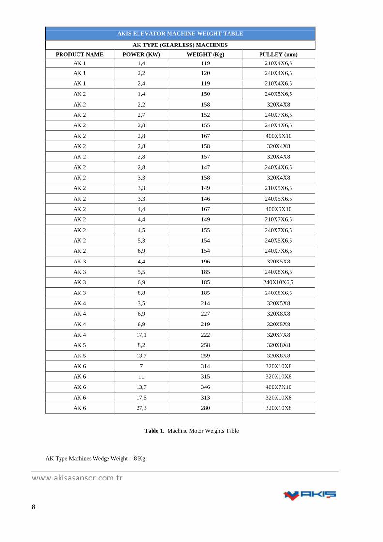
AKIS ELEVATOR MACHINE WEIGHT TABLE
AK TYPE (GEARLESS) MACHINES
PRODUCT NAME POWER (KW) WEIGHT (Kg) PULLEY (mm)
AK 1 1,4 119 210X4X6,5
AK 1 2,2 120 240X4X6,5
AK 1 2,4 119 210X4X6,5
AK 2 1,4 150 240X5X6,5
AK 2 2,2 158 320X4X8
AK 2 2,7 152 240X7X6,5
AK 2 2,8 155 240X4X6,5
AK 2 2,8 167 400X5X10
AK 2 2,8 158 320X4X8
AK 2 2,8 157 320X4X8
AK 2 2,8 147 240X4X6,5
AK 2 3,3 158 320X4X8
AK 2 3,3 149 210X5X6,5
AK 2 3,3 146 240X5X6,5
AK 2 4,4 167 400X5X10
AK 2 4,4 149 210X7X6,5
AK 2 4,5 155 240X7X6,5
AK 2 5,3 154 240X5X6,5
AK 2 6,9 154 240X7X6,5
AK 3 4,4 196 320X5X8
AK 3 5,5 185 240X8X6,5
AK 3 6,9 185 240X10X6,5
AK 3 8,8 185 240X8X6,5
AK 4 3,5 214 320X5X8
AK 4 6,9 227 320X8X8
AK 4 6,9 219 320X5X8
AK 4 17,1 222 320X7X8
AK 5 8,2 258 320X8X8
AK 5 13,7 259 320X8X8
AK 6 7 314 320X10X8
AK 6 11 315 320X10X8
AK 6 13,7 346 400X7X10
AK 6 17,5 313 320X10X8
AK 6 27,3 280 320X10X8
Table 1. Machine Motor Weights Table
AK Type Machines Wedge Weight : 8 Kg,
www.akisasansor.com.tr
9
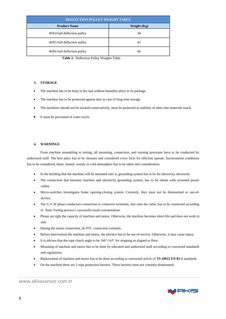
DEFLECTION PULLEY WEIGHT TABLE
Product Name Weight (Kg)
40X4 ball deflection pulley 40
40X5 ball deflection pulley 43
40X6 ball deflection pulley 44
Table 2. Deflection Pulley Weights Table
3. STORAGE
The machine has to be keep in dry and without humidity place in its package.
The machine has to be protected against dast in case of long time storage.
The machines should not be stacked consecutively, must be protected as stability of other else materials touch.
It must be prevented of water touch.
4. WARNINGS
From machine assembling to testing, all mounting, connection, and running processes have to be conducted by
authorized stuff. The best place has to be choosen and considered every facts for efficient operate. Environment conditions
has to be considered, dusty, humid, sweaty or cold atmosphere has to be taken into consideration.
In the building that the machine will be mounted onto it, grounding system has to be for electricity obviously.
The connection that between machine and electricity grounding system, has to be obtain with screened power
cables.
Micro-switches investigates brake opening-closing system. Certainly, they must not be dismounted or out-of-
service.
The U,V,W phase conductors connection to connector terminals, that onto the cable, has to be connected according
to Auto-Tuning process’s successful result concatenation.
Please set right the capacity of machine and motor. Otherwise, the machine becomes short-life and does not work in
safe.
During the motor connection, do PTC connection certainly.
Before intervention the machine and motor, the elevator has to be out-of-service. Otherwise, it may cause injury.
It is advises that the rope clutch angle to be 160°-165° for stopping as aligned to floor.
Mounting of machine and motor has to be done by educated and authorized stuff according to concerned standards
and regulations.
Replacement of machine and motor has to be done according to concerned article of TS 10922 EN 81-1 standards
On the machine there are 2 rope protection barriers. These barriers must not certainly dismounted.
www.akisasansor.com.tr
10
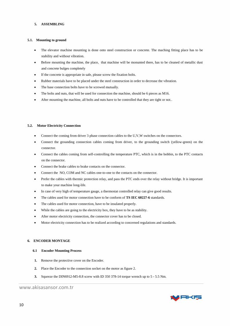
5. ASSEMBLING
5.1. Mounting to ground
The elevator machine mounting is done onto steel construction or concrete. The maching fitting place has to be
stability and without vibration.
Before mounting the machine, the place, that machine will be monunted there, has to be cleaned of metallic dust
and concrete bulges completely
If the concrete is appropriate in safe, please screw the fixation bolts.
Rubber materials have to be placed under the steel construction in order to decrease the vibration.
The base connection bolts have to be screwed mutually.
The bolts and nuts, that will be used for connection the machine, should be 6 pieces as M16.
After mounting the machine, all bolts and nuts have to be controlled that they are tight or not..
5.2. Motor Electricity Connection
Connect the coming from driver 3 phase connection cables to the U,V,W switches on the connectors.
Connect the grounding connection cables coming from driver, to the grounding switch (yellow-green) on the
connector.
Connect the cables coming from self-controlling the temperature PTC, which is in the bobbin, to the PTC contacts
on the connector.
Connect the brake cables to brake contacts on the connector.
Connect the NO, COM and NC cables one-to-one to the contacts on the connector.
Prefer the cables with thermic protection relay, and pass the PTC ends over the relay without bridge. It is important
to make your machine long-life.
In case of very high of temperature gauge, a thermostat controlled relay can give good results.
The cables used for motor connection have to be conform of TS IEC 60227-6 standards.
The cables used for motor connection, have to be insulated properly.
While the cables are going to the electricity box, they have to be as stability.
After motor electricity connection, the connector cover has to be closed.
Motor electricity connection has to be realized according to concerned regulations and standards.
6. ENCODER MONTAGE
6.1 Encoder Mounting Process
1. Remove the protective cover on the Encoder.
2. Place the Encoder to the connection socket on the motor as figure 2.
3. Squeeze the DIN6912-M5-8.8 screw with ID 350 378-14 torque wrench up to 5 - 5.5 Nm.

www.akisasansor.com.tr
11
4. Squeeze the joint screw which is on the circle joint of encoder flange with 1,2 Nm torque by ussing allen wrench
upto 2 mm.
Figure 2. Encoder Mountıng Operation
6.2 Encoder Dismounting Process
1. Remove the protective cover on the Encoder.
2. Remove M5 screw at the middle.
3. Remove the bolts on the flange connection circumference.
4. Insert M6x70 screw to the middle part of encoder to pitch and squeeze untile slacken encoder.
5. After unscrewing the Encoder by under side, remove it slowly.
www.akisasansor.com.tr
12
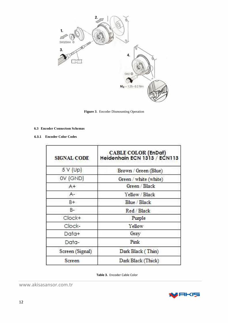
Figure 3. Encoder Dismounting Operation
6.3 Encoder Connectıon Schemas
6.3.1 Encoder Color Codes
Table 3. Encoder Cable Color

www.akisasansor.com.tr
13
6.3.2 Arkel Adrive (ECN 1313 / ECN 113)
Figure 4. Arkel Adrive Connection schema
6.3.3 Fuji Frenic Lift (ECN 1313 / ECN 113)
Figure 5. Fuji Frenic Lift Connection Schema

www.akisasansor.com.tr
14
6.3.4 Fuji Frenic Lift (ECN 1387 Sin-Cos)
Figure 6. Fuji Frenic Lift Connection Schema
6.3.5 Omron Yaskawa (ECN 1313 / ECN 113)
Figure 7. Omron Yaskawa Connection Schema
www.akisasansor.com.tr
15
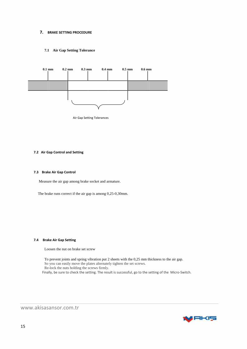
7. BRAKE SETTING PROCEDURE
7.1 Air Gap Setting Tolerance
0.1 mm 0.2 mm 0.3 mm 0.4 mm 0.5 mm 0.6 mm
7.2 Air Gap Control and Setting
7.3 Brake Air Gap Control
Measure the air gap among brake socket and armature.
The brake runs correct if the air gap is among 0,25-0,30mm.
7.4 Brake Air Gap Setting
Loosen the nut on brake set screw
To prevent joints and spring vibration put 2 sheets with the 0,25 mm thickness to the air gap.
So you can easily move the plates alternately tighten the set screws.
Re-lock the nuts holding the screws firmly.
Finally, be sure to check the setting. The result is successful, go to the setting of the Micro-Switch.
Air Gap Setting Tolerances

www.akisasansor.com.tr
16
7.5 Brake Act Checking
Activate the brake.
Check the voices during every braking.
Check the pulley turns facility as a result of brake fluctuation.
8. MICRO - SWITCHES CONTROL and SETTING
Each brake has a micro-switch
While brakes are on, micro-switches are off.
Micro-switches are cabled serially.
Control micro-switches using a ohmmeter.
Control each micro-switch respectively making short circuit the others.
Controlling must be repeated a few times activating the brake as long as turning of the brake disc at least 3 rounds
as equal distance.
The setting, must be repeated a few times while the brake is active.
Tighten softly the nut using M6 tool set, and set the screw and tighten it properly. Then lock the nut tightening
more than half round.
Apply first and second phase again.
AEMF8 AEMF9 AEMF10
CURRENT VOLTAGE 190 VDC 190 VDC 190 VDC
HOLD VOLTAGE 110 VDC 110 VDC 110 VDC
MAX. TORQUE 1000 Nm 1500 Nm 2000 Nm
SPRING QUANTITY 4x6 ADET 4x8 ADET 4x10 ADET
DELAY TIME 0,35 sn 0,35 sn 0,35 sn
BRAKE LINING
DIAMETER Ø340 mm Ø340 mm Ø340 mm
CURRENT POWER 4x135 WATT 4x135 WATT 4x135 WATT
CURRENT AMPER 4x0.7 4x0.7 4x0.7
IZOLATION CLASS F F F
IP 34 34 34
REVOLUTION 298 RPM 298 RPM 298 RPM
Table 4. Brake Date
www.akisasansor.com.tr
17
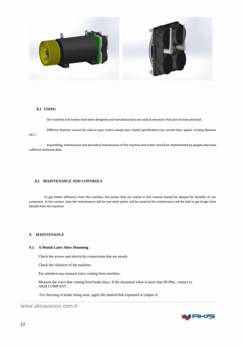
8.1 USING
Our machine and motors have been designed and manufactured to be used at elevators that carry human and load.
Different features cannot be used at your orders except your stated specifications (as carried load, speed, cruising distance
etc.).
Assembling, maintenance and periodical maintenance of the machine and motor should be implemented by people who have
sufficient technical data.
8.2 MAINTENANCE AND CONTROLS
To get better efficiency from the machine, the points that are stated in this manual should be obeyed for benefits of our
customers. In this section, how the maintenance will be and what points will be cared at the maintenance will be told to get longer time
benefit from the machine.
9. MAINTENANCE
9.1. A Month Later After Mounting
Check the screws and electricity connections that are steady.
Check the vibration of the machine.
Pay attention any unusual voice coming from machine.
Measure the voice that coming from brake discs. If the measured value is more than 60 Dba , contact to
AKIŞ COMPANY.
For checking of brake lining wear, apply the method that expressed at chapter 6.

www.akisasansor.com.tr
18
9.2 Every Year
Check the voice that coming from brake disc is lower than 60 Dba, if it is more than this value set it as expressed at
chapter 5.
Check the brake wear. If the distance is more than 0,5mm, don’t run the motor if the brakes are not active, and contact to
AKIŞ COMPANY.
10. MACHINE AND MACINE PARTS GENERAL INTRODUCTION
Introduction of the AK type (gearless) machines that manufactured by AKIŞ COMPANY, expressed at this chapter.
10.1. AK Type Machines General Introduction
AK (gearless) type makineler have lifting capability between 320-1600 kg.
New And Former Brake System Of Gearless
New generation brake system is consist of individual two rectangular magnets which are positioned next to another
one.In this brake system provides to save up substantially on the time of working air gap.In additional the working air gap is
pre-set and doesn’t have to be re-adjusted.Therefore, operation faults could be minimized and new generation system ensures
highest safety.
www.akisasansor.com.tr
19
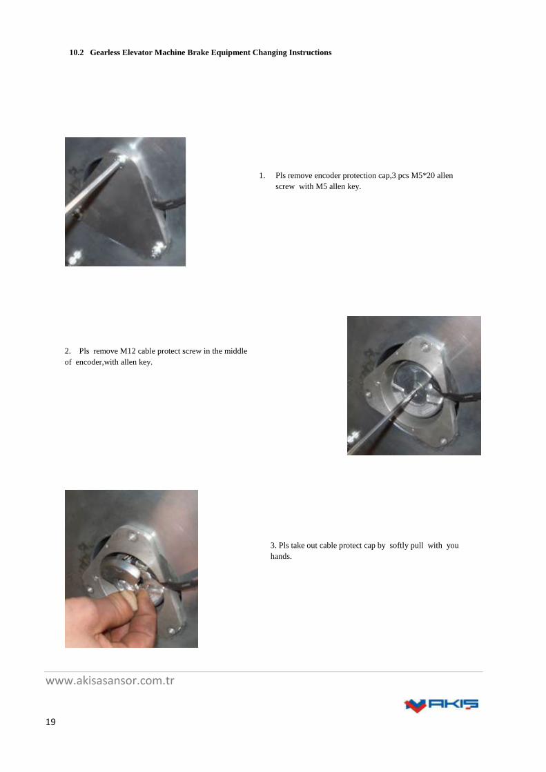
10.2 Gearless Elevator Machine Brake Equipment Changing Instructions
1. Pls remove encoder protection cap,3 pcs M5*20 allen
screw with M5 allen key.
2. Pls remove M12 cable protect screw in the middle
of encoder,with allen key.
3. Pls take out cable protect cap by softly pull with you
hands.

www.akisasansor.com.tr
20
4. Pls take out softly pull encoder jumper cable
from socket on encoder.
5. Pls remove M5*40 retainer screw in the middle of
encoder,with M4 allen key.
6. Pls remove M2 screw on top side of encoder with
M2 allen key.

www.akisasansor.com.tr
21
7. Pls insert M6 device screw to screw hole in the
middle of encoder and after tightening up adequately,
remove it softly pulling towards to out.
Removed encoder is shown in picture.
8. After removing encoder, take out the triangle encoder
socket pulling by hand.
www.akisasansor.com.tr
22
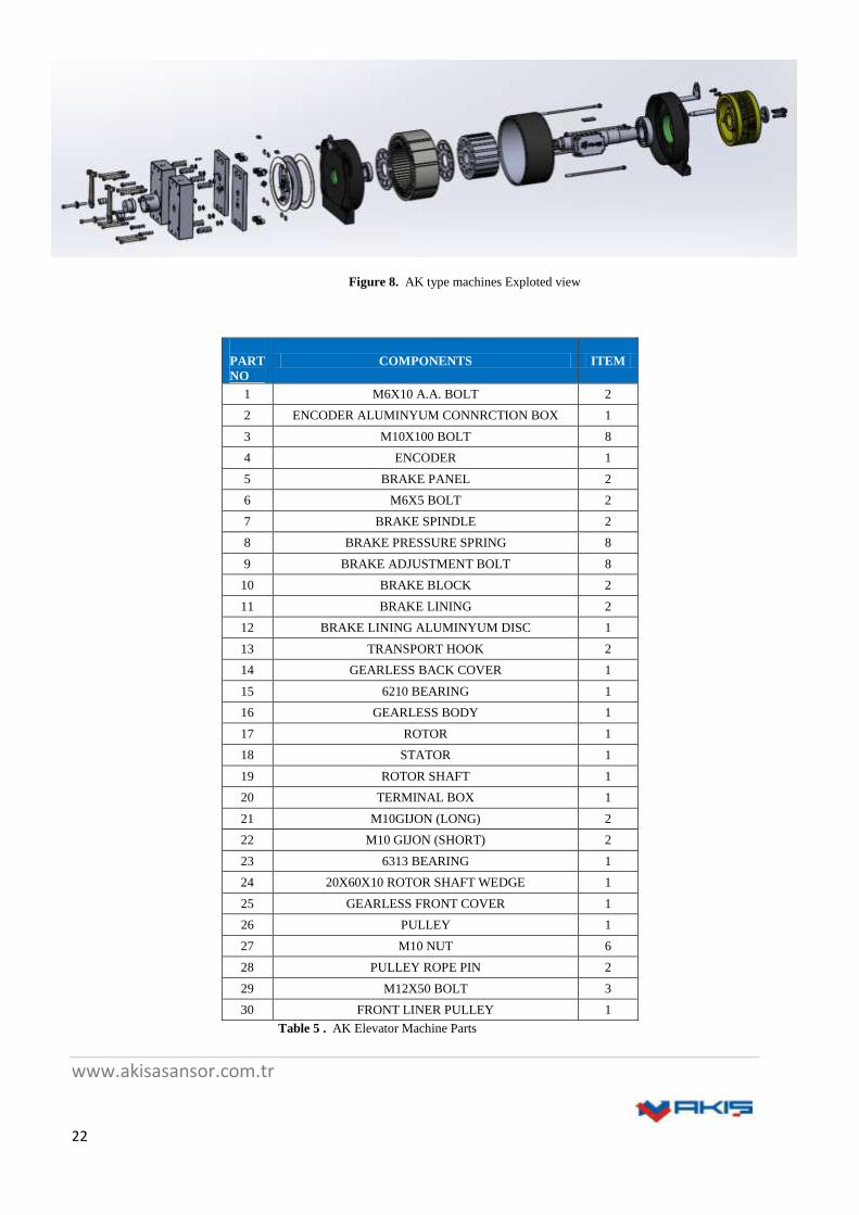
Figure 8. AK type machines Exploted view
PART
NO
COMPONENTS ITEM
1 M6X10 A.A. BOLT 2
2 ENCODER ALUMINYUM CONNRCTION BOX 1
3 M10X100 BOLT 8
4 ENCODER 1
5 BRAKE PANEL 2
6 M6X5 BOLT 2
7 BRAKE SPINDLE 2
8 BRAKE PRESSURE SPRING 8
9 BRAKE ADJUSTMENT BOLT 8
10 BRAKE BLOCK 2
11 BRAKE LINING 2
12 BRAKE LINING ALUMINYUM DISC 1
13 TRANSPORT HOOK 2
14 GEARLESS BACK COVER 1
15 6210 BEARING 1
16 GEARLESS BODY 1
17 ROTOR 1
18 STATOR 1
19 ROTOR SHAFT 1
20 TERMINAL BOX 1
21 M10GIJON (LONG) 2
22 M10 GIJON (SHORT) 2
23 6313 BEARING 1
24 20X60X10 ROTOR SHAFT WEDGE 1
25 GEARLESS FRONT COVER 1
26 PULLEY 1
27 M10 NUT 6
28 PULLEY ROPE PIN 2
29 M12X50 BOLT 3
30 FRONT LINER PULLEY 1
Table 5 . AK Elevator Machine Parts
www.akisasansor.com.tr
23
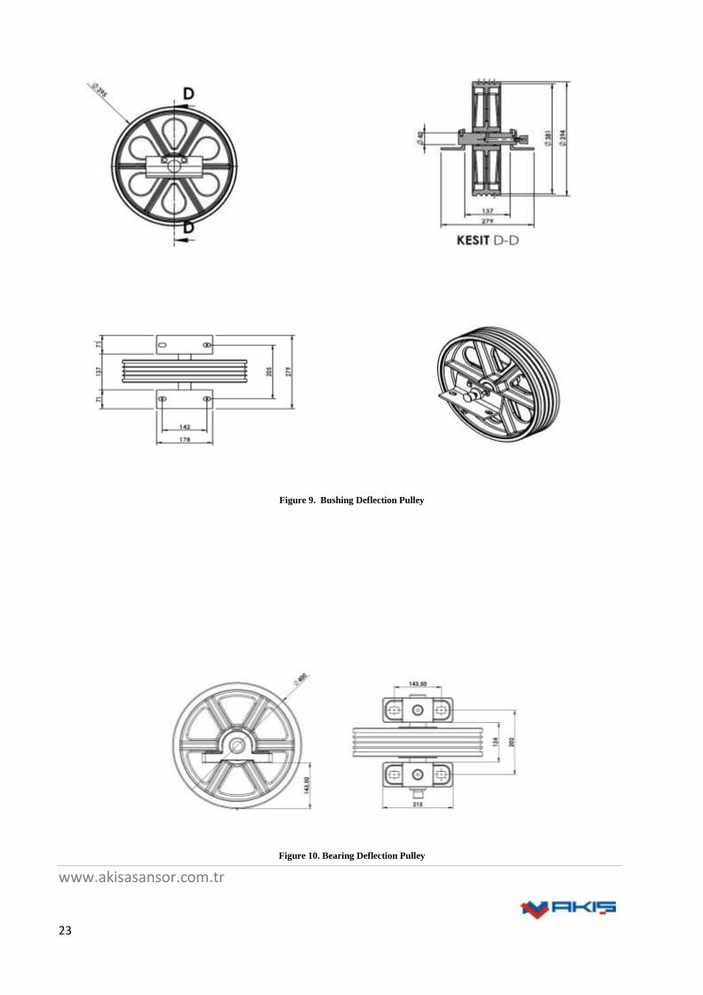
Figure 9. Bushing Deflection Pulley
Figure 10. Bearing Deflection Pulley
www.akisasansor.com.tr
24
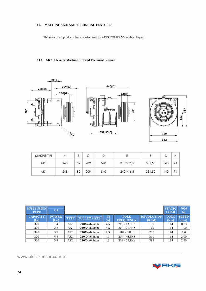
11. MACHINE SIZE AND TECHNICAL FEATURES
The sizes of all products that manufactured by AKIŞ COMPANY in this chapter.
11.1. AK 1 Elevator Machine Size and Technical Feature
SUSPENSION
TYPE 2:1
STATIC
LOAD
7000
kg
CAPACITY
(kg)
POWER
(kw) TYPE PULLEY SIZES
IN
(A)
POLE
FREQUENCY
REVOLUTION
(RPM)
TORC
(Nm)
SPEED
(m/s)
320 1,4 AK1 210X4x6,5mm 4,5 20P - 13.3Hz 100 114 0,63
320 2,2 AK1 210X4x6,5mm 5,5 20P - 21,4Hz 160 114 1,00
320 3,5 AK1 210X4x6,5mm 9,5 20P - 34Hz 255 114 1,6
320 4,4 AK1 210X4x6,5mm 11 20P - 42,6Hz 319 114 2,00
320 5,5 AK1 210X4x6,5mm 13 20P - 53,1Hz 398 114 2,50
www.akisasansor.com.tr
25
SUSPENSION
TYPE 2:1
STATICK
LOAD
7000
kg
CAPACITY
(kg)
POWER
(kw) TYPE
PULLEY
SIZES
IN
(A)
POLE
FREQUENCY
REVOLUTION
(RPM)
TORC
(Nm)
SPEED
(m/s)
320 1,4 AK1 240x4x6,5mm 4,5 20P - 13.3Hz 100 132 0,63
320 2,2 AK1 240x4x6,5mm 5,5 20P - 21.3Hz 160 132 1,00
320 3,5 AK1 240x4x6,5mm 9,5 20P - 34Hz 255 132 1,60
320 4,4 AK1 240x4x6,5mm 11 20P - 42.5Hz 319 132 2,00
320 5,5 AK1 240x4x6,5mm 13 20P - 53Hz 398 132 2,50
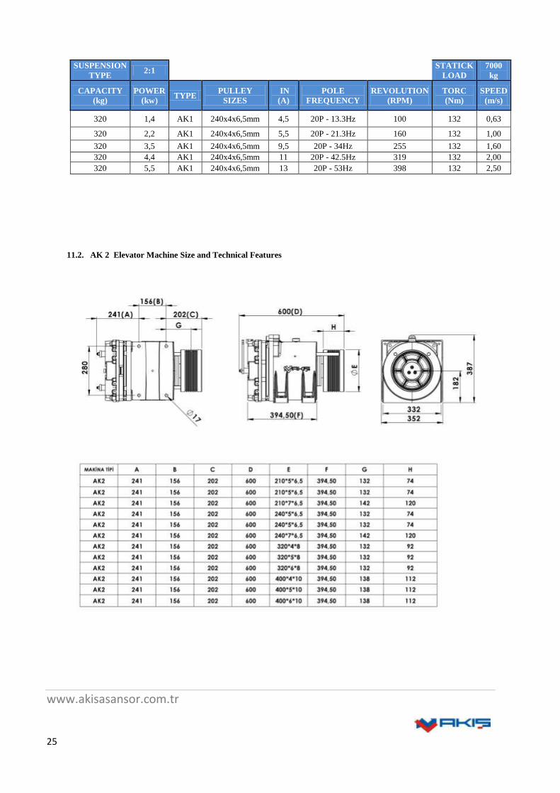
11.2. AK 2 Elevator Machine Size and Technical Features

www.akisasansor.com.tr
26
SUSPENSION
TYPE 2:1
STATIC
LOAD 7000 kg
CAPACITY
(kg)
POWER
(kw) TYPE
PULLEY
SIZES
IN
(A)
POLE
FREQUENC
Y
REVOLUTION
(RPM)
TORC
(Nm)
SPEED
(m/s)
400 1,7 AK2 210X4x6,5mm 6 20P 13.3Hz 100 143 0,63
480 2,1 AK2 210X5x6,5mm 7 20P 13.3Hz 100 171 0,63
630 2,7 AK2 210X7x6,5mm 8,5 20P 13.3Hz 100 225 0,63
400 2,8 AK2 210X4x6,5mm 7,5 20P - 21,4Hz 160 143 1,00
480 3,3 AK2 210X5x6,5mm 9 20P - 21,4Hz 160 171 1,00
630 4,4 AK2 210X7x6,5mm 12 20P - 21,4Hz 160 225 1,00
400 4,4 AK2 210X4x6,5mm 11,5 20P - 34Hz 255 143 1,60
480 5,3 AK2 210X5x6,5mm 14 20P - 34Hz 255 171 1,60
630 6,9 AK2 210X7x6,5mm 18 20P - 34Hz 255 225 1,60
400 5,5 AK2 210X4x6,5mm 13 20P - 42,6Hz. 319 143 2,00
480 6,6 AK2 210X5x6,5mm 16 20P - 42,6Hz. 319 171 2,00
630 8,6 AK2 210X7x6,5mm 20 20P - 42,6Hz. 319 225 2,00
400 6,9 AK2 210X4x6,5mm 16 20P - 53,1Hz. 398 143 2,50
480 8,2 AK2 210X5x6,5mm 19 20P - 53,1Hz. 398 171 2,50
630 10,8 AK2 210X7x6,5mm 25 20P - 53,1Hz. 398 225 2,50
SUSPENSION
TYPE 2:1
STATIC
LOAD 7000 kg
CAPACITY
(kg)
POWER
(kw) TYPE
PULLEY
SIZES
IN
(A)
POLE
FREQUENC
Y
REVOLUTION
(RPM)
TORC
(Nm)
SPEED
(m/s)
400 1,7 AK2 240x4x6,5mm 6 20P - 13.3Hz 100 164 0,63
480 2,1 AK2 240x5x6,5mm 7 20P - 13.3Hz 100 196 0,63
630 2,7 AK2 240x7x6,5mm 8,5 20P - 13.3Hz 100 258 0,63
400 2,8 AK2 240x4x6,5mm 7,5 20P - 21.3Hz 160 164 1,00
480 3,3 AK2 240x5x6,5mm 9 20P - 21.3Hz 160 196 1,00
630 4,4 AK2 240x7x6,5mm 12 20P - 21.3Hz 160 258 1,00
400 4,4 AK2 240x4x6,5mm 11,5 20P - 34Hz 255 164 1,60
480 5,3 AK2 240x5x6,5mm 14 20P - 34Hz 255 196 1,60
630 6,9 AK2 240x7x6,5mm 18 20P - 34Hz 255 258 1,60
400 5,5 AK2 240x4x6,5mm 13 20P - 42.5Hz. 319 164 2,00
480 6,6 AK2 240x5x6,5mm 16 20P - 42.5Hz. 319 196 2,00
630 8,6 AK2 240x7x6,5mm 20 20P - 42.5Hz. 319 258 2,00
400 6,9 AK2 240x4x6,5mm 16 20P - 53Hz. 398 164 2,50
480 8,2 AK2 240x5x6,5mm 19 20P - 53Hz. 398 196 2,50
630 10,8 AK2 240x7x6,5mm 25 20P - 53Hz. 398 258 2,50

www.akisasansor.com.tr
27
SUSPENSION
TYPE 2:1
STATIC
LOAD
7000
kg
CAPACITY
(kg)
POWER
(kw) TYPE PULLEY SIZES
IN
(A)
POLE
FREQUENCY
REVOLUTION
(RPM)
TORC
(Nm)
SPEED
(m/s)
320 1,4 AK2 320x4x8mm 5 20P - 10Hz 76 175 0,63
400 1,8 AK2 320x4x8mm 5,5 20P - 10Hz 76 218 0,63
480 2,1 AK2 320x4x8mm 6,5 20P - 10Hz 76 262 0,63
320 2,2 AK2 320x4x8mm 6 20P - 15.92Hz 120 175 1,00
400 2,8 AK2 320x4x8mm 8 20P - 15.92Hz 120 218 1,00
480 3,3 AK2 320x4x8mm 9,5 20P - 15.92Hz 120 262 1,00
320 3,5 AK2 320x4x8mm 10 20P - 25.5Hz 191 175 1,60
400 4,4 AK2 320x4x8mm 12,5 20P - 25.5Hz 191 218 1,60
480 5,3 AK2 320x4x8mm 14,5 20P - 25.5Hz 191 262 1,60
320 4,4 AK2 320x4x8mm 10,5 20P - 42.5Hz. 239 175 2,00
400 5,5 AK2 320x4x8mm 13 20P - 42.5Hz. 239 218 2,00
480 6,6 AK2 320x5x8mm 15,5 20P - 42.5Hz. 239 262 2,00
320 5,5 AK2 320x5x8mm 13 20P - 53Hz. 299 175 2,50
400 6,9 AK2 320x5x8mm 16,5 20P - 53Hz. 299 218 2,50
480 8,2 AK2 320x6x8mm 20 20P - 53Hz. 299 262 2,50
SUSPENSION
TYPE 2:1
STATIC
LOAD 7000 kg
CAPACITY
(kg)
POWER
(kw) TYPE
PULLEY
SIZES
IN
(A)
POLE
FREQUENCY
REVOLUTION
(RPM)
TORC
(Nm)
SPEED
(m/s)
320 1,4 AK2 400x4x10mm 5,5 20P - 8.1Hz 60 218 0,63
400 1,8 AK2 400x4x10mm 6 20P - 8.1Hz 60 273 0,63
320 2,2 AK2 400x4x10mm 7 20P - 12.8Hz 96 218 1,00
400 2,8 AK2 400x4x10mm 8 20P - 12.8Hz 96 273 1,00
320 3,5 AK2 400x4x10mm 10 20P - 20.4Hz 153 218 1,60
400 4,4 AK2 400x5x10mm 13 20P - 20.4Hz 153 273 1,60
320 4,4 AK2 400x4x10mm 10 20P - 25.46Hz. 191 218 2,00
400 5,5 AK2 400x5x10mm 13 20P - 25.46Hz. 191 273 2,00
320 5,5 AK2 400x6x10mm 13 20P - 31.9Hz. 239 218 2,50
400 6,9 AK2 400x6x10mm 16 20P - 31.9Hz. 239 273 2,50
SUSPENSION
TYPE 1:1
STATIC
LOAD 3500 kg
CAPACITY
(kg)
POWER
(kw) TYPE
PULLEY
SIZES
IN
(A)
POLE
FREQUENCY
REVOLUTION
(RPM)
TORC
(Nm)
SPEED
(m/s)
320 1,4 AK2 240x5x6,5mm 5 20P - 6.66Hz 50 235 0,63
320 2,2 AK2 240x5x6,5mm 6,5 20P - 10.66Hz 80 235 1,00
320 3,5 AK2 240x5x6,5mm 10 20P - 17Hz 128 235 1,60
320 4,5 AK2 240x5x6,5mm 14 20P - 21.4Hz 160 235 2,00

www.akisasansor.com.tr
28
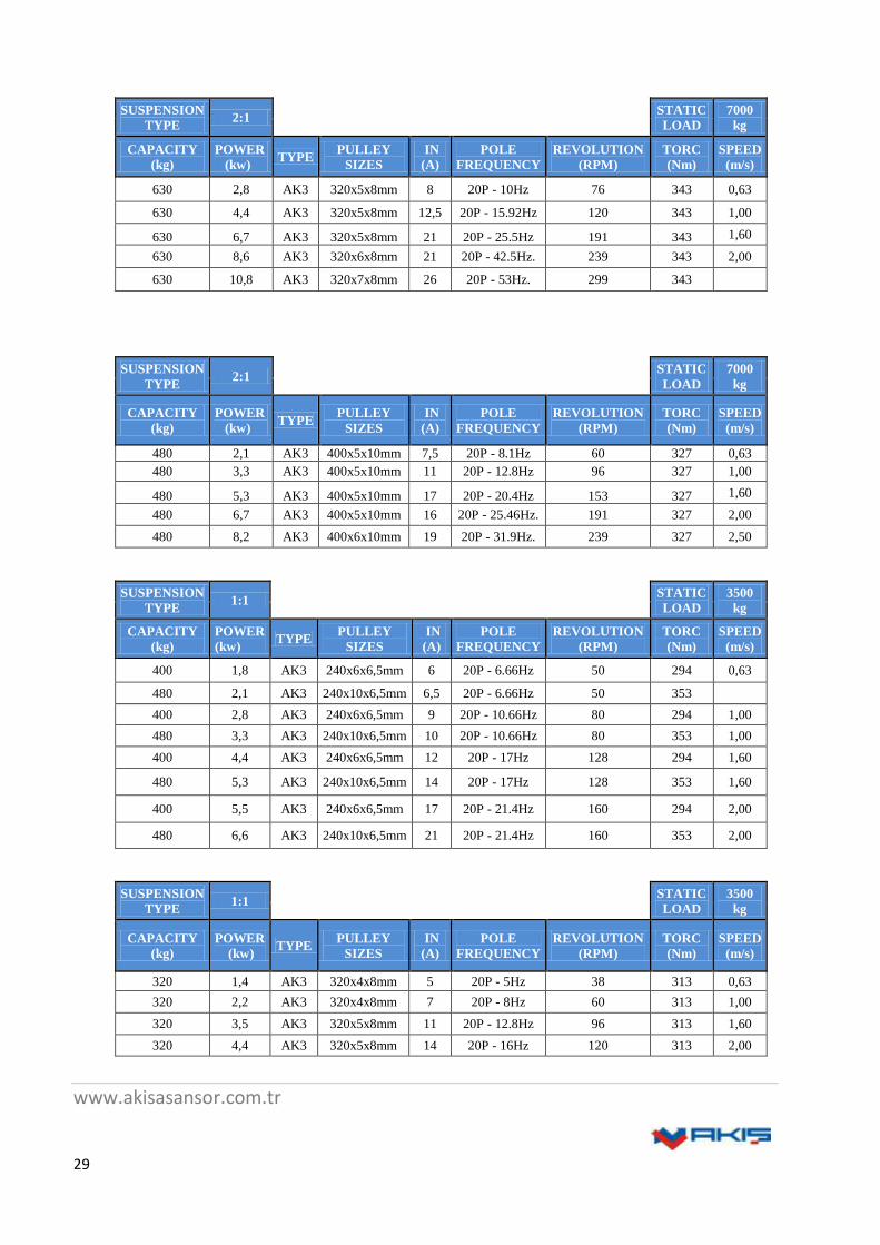
11.3. AK 3 Elevator Machine Size and Technical Features
SUSPENSION
TYPE 2:1
STATIC
LOAD 7000 kg
CAPACITY
(kg)
POWER
(kw) TYPE
PULLEY
SIZES
IN
(A)
POLE
FREQUENCY
REVOLUTION
(RPM)
TORC
(Nm)
SPEED
(m/s)
800 3,5 AK3 240x8x6,5mm 12 20P - 13.3Hz 100 328 0,63
1000 4,3 AK3 240x10x6,5mm 12 20P - 13.3Hz 100 410 0,63
800 5,5 AK3 240x8x6,5mm 14,5 20P - 21.3Hz 160 328 1,00
1000 6,9 AK3 240x10x6,5mm 18 20P - 21.3Hz 160 410 1,00
800 8,8 AK3 240x8x6,5mm 22 20P - 34Hz 255 328 1,60
1000 11 AK3 240x10x6,5mm 27,5 20P - 34Hz 255 410 1,60
800 11 AK3 240x8x6,5mm 26 20P - 42.5Hz. 319 328 2,00
1000 13,7 AK3 240x10x6,5mm 32 20P - 42.5Hz. 319 410 2,00
800 13,7 AK3 240x8x6,5mm 32 20P - 53Hz. 398 328 2,50
1000 17,1 AK3 240x10x6,5mm 40 20P - 53Hz. 398 410 2,50
www.akisasansor.com.tr
29
SUSPENSION
TYPE 2:1
STATIC
LOAD
7000
kg
CAPACITY
(kg)
POWER
(kw) TYPE
PULLEY
SIZES
IN
(A)
POLE
FREQUENCY
REVOLUTION
(RPM)
TORC
(Nm)
SPEED
(m/s)
630 2,8 AK3 320x5x8mm 8 20P - 10Hz 76 343 0,63
630 4,4 AK3 320x5x8mm 12,5 20P - 15.92Hz 120 343 1,00
630 6,7 AK3 320x5x8mm 21 20P - 25.5Hz 191 343 1,60
630 8,6 AK3 320x6x8mm 21 20P - 42.5Hz. 239 343 2,00
630 10,8 AK3 320x7x8mm 26 20P - 53Hz. 299 343
SUSPENSION
TYPE 2:1
STATIC
LOAD
7000
kg
CAPACITY
(kg)
POWER
(kw) TYPE
PULLEY
SIZES
IN
(A)
POLE
FREQUENCY
REVOLUTION
(RPM)
TORC
(Nm)
SPEED
(m/s)
480 2,1 AK3 400x5x10mm 7,5 20P - 8.1Hz 60 327 0,63
480 3,3 AK3 400x5x10mm 11 20P - 12.8Hz 96 327 1,00
480 5,3 AK3 400x5x10mm 17 20P - 20.4Hz 153 327 1,60
480 6,7 AK3 400x5x10mm 16 20P - 25.46Hz. 191 327 2,00
480 8,2 AK3 400x6x10mm 19 20P - 31.9Hz. 239 327 2,50
SUSPENSION
TYPE 1:1
STATIC
LOAD
3500
kg
CAPACITY
(kg)
POWER
(kw) TYPE
PULLEY
SIZES
IN
(A)
POLE
FREQUENCY
REVOLUTION
(RPM)
TORC
(Nm)
SPEED
(m/s)
400 1,8 AK3 240x6x6,5mm 6 20P - 6.66Hz 50 294 0,63
480 2,1 AK3 240x10x6,5mm 6,5 20P - 6.66Hz 50 353
400 2,8 AK3 240x6x6,5mm 9 20P - 10.66Hz 80 294 1,00
480 3,3 AK3 240x10x6,5mm 10 20P - 10.66Hz 80 353 1,00
400 4,4 AK3 240x6x6,5mm 12 20P - 17Hz 128 294 1,60
480 5,3 AK3 240x10x6,5mm 14 20P - 17Hz 128 353 1,60
400 5,5 AK3 240x6x6,5mm 17 20P - 21.4Hz 160 294 2,00
480 6,6 AK3 240x10x6,5mm 21 20P - 21.4Hz 160 353 2,00
SUSPENSION
TYPE 1:1
STATIC
LOAD
3500
kg
CAPACITY
(kg)
POWER
(kw) TYPE
PULLEY
SIZES
IN
(A)
POLE
FREQUENCY
REVOLUTION
(RPM)
TORC
(Nm)
SPEED
(m/s)
320 1,4 AK3 320x4x8mm 5 20P - 5Hz 38 313 0,63
320 2,2 AK3 320x4x8mm 7 20P - 8Hz 60 313 1,00
320 3,5 AK3 320x5x8mm 11 20P - 12.8Hz 96 313 1,60
320 4,4 AK3 320x5x8mm 14 20P - 16Hz 120 313 2,00

www.akisasansor.com.tr
30
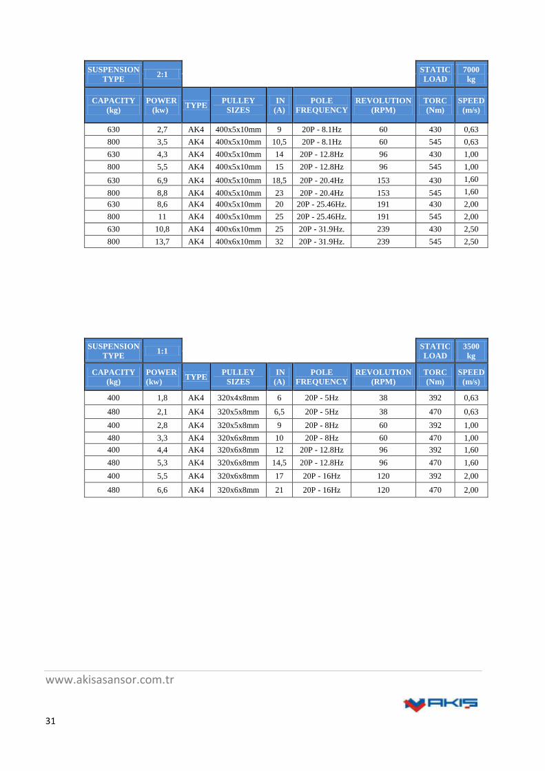
11.4. AK 4 Elevator Machine Size and Technical Features
SUSPENSION
TYPE 2:1
STATIC
LOAD 7000 kg
CAPACITY
(kg)
POWER
(kw) TYPE
PULLEY
SIZES
IN
(A)
POLE
FREQUENCY
REVOLUTION
(RPM)
TORC
(Nm)
SPEED
(m/s)
800 3,5 AK4 320x5x8mm 10,5 20P - 10Hz 76 436 0,63
1000 4,4 AK4 320x7x8mm 12,5 20P - 10Hz 76 545 0,63
800 5,5 AK4 320x5x8mm 15 20P - 15.92Hz 120 436 1,00
1000 6,9 AK4 320x7x8mm 18 20P - 15.92Hz 120 545 1,00
800 8,8 AK4 320x5x8mm 23 20P - 25.5Hz 191 436 1,60
1000 11 AK4 320x7x8mm 30 20P - 25.5Hz 191 545 1,60
800 11 AK4 320x7x8mm 26 20P - 42.5Hz. 239 436 2,00
1000 13,7 AK4 320x8x8mm 33 20P - 42.5Hz. 239 545 2,00
800 13,7 AK4 320x8x8mm 32 20P - 53Hz. 299 436 2,50
1000 17,1 AK4 320x9x8mm 40 20P - 53Hz. 299 545 2,50
www.akisasansor.com.tr
31
SUSPENSION
TYPE 2:1
STATIC
LOAD
7000
kg
CAPACITY
(kg)
POWER
(kw) TYPE
PULLEY
SIZES
IN
(A)
POLE
FREQUENCY
REVOLUTION
(RPM)
TORC
(Nm)
SPEED
(m/s)
630 2,7 AK4 400x5x10mm 9 20P - 8.1Hz 60 430 0,63
800 3,5 AK4 400x5x10mm 10,5 20P - 8.1Hz 60 545 0,63
630 4,3 AK4 400x5x10mm 14 20P - 12.8Hz 96 430 1,00
800 5,5 AK4 400x5x10mm 15 20P - 12.8Hz 96 545 1,00
630 6,9 AK4 400x5x10mm 18,5 20P - 20.4Hz 153 430 1,60
800 8,8 AK4 400x5x10mm 23 20P - 20.4Hz 153 545 1,60
630 8,6 AK4 400x5x10mm 20 20P - 25.46Hz. 191 430 2,00
800 11 AK4 400x5x10mm 25 20P - 25.46Hz. 191 545 2,00
630 10,8 AK4 400x6x10mm 25 20P - 31.9Hz. 239 430 2,50
800 13,7 AK4 400x6x10mm 32 20P - 31.9Hz. 239 545 2,50
SUSPENSION
TYPE 1:1
STATIC
LOAD
3500
kg
CAPACITY
(kg)
POWER
(kw) TYPE
PULLEY
SIZES
IN
(A)
POLE
FREQUENCY
REVOLUTION
(RPM)
TORC
(Nm)
SPEED
(m/s)
400 1,8 AK4 320x4x8mm 6 20P - 5Hz 38 392 0,63
480 2,1 AK4 320x5x8mm 6,5 20P - 5Hz 38 470 0,63
400 2,8 AK4 320x5x8mm 9 20P - 8Hz 60 392 1,00
480 3,3 AK4 320x6x8mm 10 20P - 8Hz 60 470 1,00
400 4,4 AK4 320x6x8mm 12 20P - 12.8Hz 96 392 1,60
480 5,3 AK4 320x6x8mm 14,5 20P - 12.8Hz 96 470 1,60
400 5,5 AK4 320x6x8mm 17 20P - 16Hz 120 392 2,00
480 6,6 AK4 320x6x8mm 21 20P - 16Hz 120 470 2,00
www.akisasansor.com.tr
32
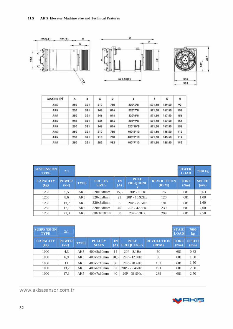
11.5 AK 5 Elevator Machine Size and Technical Features
SUSPENSION
TYPE 2:1
STATIC
LOAD 7000 kg
CAPACITY
(kg)
POWER
(kw) TYPE
PULLEY
SIZES
IN
(A)
POLE
FREQUENC
Y
REVOLUTION
(RPM)
TORC
(Nm)
SPEED
(m/s)
1250 5,5 AK5 320x8x8mm 15,5 20P - 10Hz 76 681 0,63
1250 8,6 AK5 320x8x8mm 23 20P - 15.92Hz 120 681 1,00
1250 13,7 AK5 320x8x8mm 35 20P - 25.5Hz 191 681 1,60
1250 17,1 AK5 320x9x8mm 40 20P - 42.5Hz. 239 681 2,00
1250 21,3 AK5 320x10x8mm 50 20P - 53Hz. 299 681 2,50
SUSPENSION
TYPE 2:1
STAIC
LOAD
7000
kg
CAPACITY
(kg)
POWER
(kw) TYPE
PULLEY
SIZES
IN
(A)
POLE
FREQUENCY
REVOLUTION
(RPM)
TORC
(Nm)
SPEED
(m/s)
1000 4,3 AK5 400x5x10mm 14 20P - 8.1Hz 60 681 0,63
1000 6,9 AK5 400x5x10mm 18,5 20P - 12.8Hz 96 681 1,00
1000 11 AK5 400x5x10mm 30 20P - 20.4Hz 153 681 1,60
1000 13,7 AK5 400x6x10mm 32 20P - 25.46Hz. 191 681 2,00
1000 17,1 AK5 400x7x10mm 40 20P - 31.9Hz. 239 681 2,50

www.akisasansor.com.tr
33
SUSPENSION
TYPE 1:1
STATIC
LOAD 3500 kg
CAPACITY
(kg)
POWER
(kw) TYPE
PULLEY
SIZES
IN
(A)
POLE
FREQUENCY
REVOLUTION
(RPM)
TORC
(Nm)
SPEED
(m/s)
630 2,8 AK5 320x6x8mm 9 20P - 5Hz 38 618 0,63
630 4,4 AK5 320x7x8mm 12 20P - 8Hz 60 618 1,00
630 6,9 AK5 320x8x8mm 17 20P - 12.8Hz 96 618 1,60
630 8,7 AK5 320x8x8mm 27 20P - 16Hz 120 618 2,00
11.6. AK 6 Elevator Machine Size and Technical Features
SUSPENSION
TYPE 2:1
STATIC
LOAD 7000 kg
CAPACITY
(kg)
POWER
(kw) TYPE
PULLEY
SIZES
IN
(A)
POLE
FREQUENCY
REVOLUTION
(RPM)
TORC
(Nm)
SPEED
(m/s)
1600 7 AK6 320x10x8mm 17,5 20P - 10Hz 76 872 0,63
1600 11 AK6 320x10x8mm 28 20P - 15.92Hz 120 872 1,00
1600 17,5 AK6 320x10x8mm 45 20P - 25.5Hz 191 872 1,60
1600 22 AK6 320x10x8mm 52 20P - 42.5Hz. 239 872 2,00
1600 27,3 AK6 320x10x8mm 64 20P - 53Hz. 299 872 2,50

www.akisasansor.com.tr
34
SUSPENSION
TYPE 2:1
STATIC
LOAD 7000 kg
CAPACITY
(kg)
POWER
(kw) TYPE
PULLEY
SIZES
IN
(A)
POLE
FREQUENCY
REVOLUTION
(RPM)
TORC
(Nm)
SPEED
(m/s)
1250 5,4 AK6 400x7x10mm 15 20P - 8.1Hz 60 852 0,63
1250 8,6 AK6 400x7x10mm 23 20P - 12.8Hz 96 852 1,00
1250 13,7 AK6 400x7x10mm 32 20P - 20.4Hz 153 852 1,60
1250 17,1 AK6 400x7x10mm 40 20P - 25.46Hz. 191 852 2,00
1250 21,3 AK6 400x7x10mm 50 20P - 31.9Hz. 239 852 2,50

www.akisasansor.com.tr
35
12. ERROR RECOVERY
ERROR REASON SOLUTION
THE NOISE WHEN
MACHINE RUNING
VVVF SETTINGS ARE INCORRECT. Control VVVF Settıngs.
Encoder Failed. Change Encoder.
Bearing Damaged. Please Contact Customer Service.
Over heat
Medium Temperature Over +40˚ Develop The Ventilation System
VVVF Settings Incorrect. Control VVVF Settıngs.
Motor Does Not Start.
Motor Phases Are Connected İncorrectly. Check The Connections Of The Motor Phase.
VVVF Faild. VVVF'i kontrol ediniz.
Brake Does Not Release. Refer To Brake Failure.
Brake noise.
Brake Connected To DC Phases. Connect To AC . Add High-voltage protection.
Air gap too large. Replace brake discs cooled range.
Brake Does Not Release.
The power supply is too low. The voltage
are not enough for brakes.
Check the power supply. Change the size of
cable.
Brake control wrong. Check the connection of the brake.
Brake coil defective. Chnage The Brake and use onginal AKIŞ
ELEVATOR Pieces.
Brake worn-out. Change Brake Discs and Use AKIŞ ELEVATOR
MACHINE Pieces.
Brake on-off
monitoring Does not wrench.
Micro-switchs are Faild. Change Micro-switchs or Brake.
Contacts are contaminated. Wrench Micro-switchs With higher current (at
least 10 mA) or Change micro-switchs.
ENSURE THAT THE QUALİFİED PERSONNEL İN THE
ENGINE ADJUST ELECTRICAL CONNECTION.

www.akisasansor.com.tr
36

www.akisasansor.com.tr
37
www.akisasansor.com.tr
38

www.akisasansor.com.tr
39

www.akisasansor.com.tr
40
www.akisasansor.com.tr
41
www.akisasansor.com.tr
42

www.akisasansor.com.tr
43

www.akisasansor.com.tr
44

www.akisasansor.com.tr
45

www.akisasansor.com.tr
46
www.akisasansor.com.tr
47

www.akisasansor.com.tr
48

www.akisasansor.com.tr
49

www.akisasansor.com.tr
50

www.akisasansor.com.tr
51

www.akisasansor.com.tr
52

www.akisasansor.com.tr
53