arup building the structure
TRANSCRIPT

8/7/2019 ARUP Building the Structure
http://slidepdf.com/reader/full/arup-building-the-structure 1/12
40 The Arup Journal 2/2008
CCTV Headquarters,Beijing, China:
Building the structure
Erecting two massive leaning Towers, and connectingthem with a 9-13 storey Overhang suspended36 storeys in the air, presented the structural engineersand contractors with unprecedented design andconstruction challenges.
This is the third Arup Journal article about the CCTV(China Central Television) building in Beijing; it coversthe construction of this unique project. The previoustwo articles dealt with the structural 1 and servicesengineering 2 design.
Introduction
China Central Television (CCTV) had been expandigreatly, in competition with major internationaltelevision and news service providers, and early in2002 it organised an international design competitiofor a new headquarters. This was won by the team oOMA (Ofce for Metropolitan Architecture) and Ar
The team subsequently allied with the East ChinaDesign Institute (ECADI) to act as the essential locadesign institute for both architecture and engineeringThe rst Arup Journal article1 outlined the designcollaboration process.
The unusual brief, in television terms, was forall the functions of production, management, andadministration to be contained on the chosen site inthe new Beijing Central Business District, but notnecessarily in one building.
In its architectural response, however, OMAdecided that by doing just this, it should be possibleto break down the “ghettoes” that tend to form in acomplex and compartmentalised process like makingtelevision programmes, and create a building whoselayout in three dimensions would force all thoseinvolved to mix and produce a better end-productmore economically and efciently (Fig 1).
The winning design for the 473 000m 2, 234mtall CCTV building thus combines administrationand ofces, news and broadcasting, programmeproduction, and services – the entire process of Chinese television – in a single loop of interconnectactivities (Fig 2) around the four elements of thebuilding: the nine-storey “Base”, the two leaningTowers that slope at 6° in two directions, and the9-13 storey “Overhang”, suspended 36 storeys in
the air. The public facilities are in a second building,the Television Cultural Centre (TVCC), and both arelinked to a third service building that houses majorplant as well as security.
The whole development will provide 599 000m²gross oor area and covers 187 000m², including alandscaped media park with external features.
Construction Documents phase
In August 2004, after receiving approval for thestructural design from the Chinese Ministry of Construction, Arup handed over the extendedpreliminary design (EPD) documents to ECADI, whthen began to produce the Construction Documents(CDs). Arup, however, maintained an extensiveinvolvement on completion of the EPD design phaseincluding production of tender documentation for thmain structure and interaction with the tenderers forthe works, as well as being part of the tender reviewprocess. Together with the architects OMA, Arupalso had a continuous site presence duringconstruction, working with the contractor inimplementing the design (Fig 3).
Chris Carroll Craig Gibbons Goman Ho Michael KwokRichard Lawson Alexis Lee Ronald Li Andrew LuongRory McGowan Chas Pope
1. Architect’s illustration of the completed building.

8/7/2019 ARUP Building the Structure
http://slidepdf.com/reader/full/arup-building-the-structure 2/12
The Arup Journal 2/2
As previously described 1, the building’s shape and form meant that it fell outsidethe prescriptive codes for buildings in China. In consequence, a rigorous series of meetings was required with an assembled expert panel comprising 12 professorsfrom around China, appointed by the Ministry of Construction. Dialogue with theseexperts inuenced the approach to the design and determined the extent of analysisrequired to justify the seismic performance of the building.
As part of the expert panel approval process 1, several suggestions were madethat Arup and ECADI subsequently addressed during the CD phase. These includeda requirement for three physical tests to be carried out, in order to verify theanalytical calculations:
of the column-brace joint to conrm its performance under cyclical loading, inparticular the requirement that failure takes place by yielding of the element ratherthan at the connection.
1:5 scale models of the project’s non-standard steel reinforced columns. Thesetests resulted from concerns that the high structural steel ratio might lead toreduced ductility.
constructed to test the structural performance under several seismic eventsincluding a severe design earthquake (known as Level 3 - average return period of 1 in 2475 years). The tests were undertaken by the China Academy of BuildingResearch (CABR) in Beijing, using the largest shaking table outside America orJapan (Fig 4 overleaf).
This large-scale shaking table test was of particular interest. In China it is the normfor buildings that fall outside the code to be thus studied, and the CCTV model wasthe largest and most complex tested to date. The nature of the testing required theprimary structural elements to be made from copper (to replicate as much as possiblein a scale sense the ductility of steel). The model also included concrete oors(approximately 8mm thick) to represent the 150mm thick composite oor slabs.
Interestingly, in a scaled model test the duration of the earthquake is also scaled,so that the severe design earthquake event lasted less than four seconds whenapplied to the model.
2004
Competition
2002 2003 2005 2006 2007 2008
Jury decision
Contract negotiation
Scheme design stage
22 December 2002:signing of design contract
Extended preliminarydesign stage
Structural expert panel
review approvalExtended preliminarydesign revisions
Constructiondocuments stage
Construction phase
Excavation
Piling and raftfoundations
Basement
SuperstructuresteelworkCladdinginstallation
Fit-out
8 January 2004
22 September 2004:groundbreaking ceremony
28 April 2006: constructiondocuments approval
28 April 2005: maincontractor enters site
13 February 2006:steel installation started
1 August 2007: construction of Overhang starts 8 December 2007: connection of Overhang
26 December 2007: Overhang connection ceremony 27 March 2008: topping-out ceremony
2. Functions and layout within the CCTV building.
3. CCTV timeline.
VIP elevators
Studios
Studios
Presidentsuite
Executiveoor
Cafe andmeeting
VIPlobby
Healthcentre
Broadcasting
Public space and circulation
Studio and broadcast
Staff and VIP facilities
Executiveelevators
Expresselevators
VIPlounge
VIPlounge
Canteen
Towerlobby
VIPlobby
Marketingdepartment
Sports hallVIP loungeCentral kitchen
Staff canteenGym
Towerlobby
Sky studio
Studios
Openstudios
Publiclobby

8/7/2019 ARUP Building the Structure
http://slidepdf.com/reader/full/arup-building-the-structure 3/12
42 The Arup Journal 2/2008
After the connection was made, any added weight would result in a thrust betweenthe two Towers via the Overhang. The nal stresses in the building were therefore verymuch linked to the construction sequence. The Particular Specication dened anupper and lower bound range of permissible locked-in stress, allowing the contractorsome exibility in choosing his nal construction sequence.
Another interesting feature of the process was the proposals put forward bydifferent tenderers to meet the Particular Specication requirements and theparticularly challenging aspects of the Overhang construction. One of the threeshortlisted tenderers proposed a temporary tower the full 162m height to theunderside of the Overhang, providing a working platform to build the Overhangconnection in situ. The second tenderer opted to build a partial cantilever from the
Towers and then construct the lower part of the Overhang at ground level and strandjack the assembly into position. The third tenderer proposed to construct incrementalcantilevers from each Tower until the two met and connected at the centre of theOverhang (Fig 5). This latter approach was as described in Arup’s documentation,though any construction approach was deemed acceptable provided it could satisfythe locked-in stress limits dened in the Particular Specication.
The Particular Technical Specication approach has become a leading example of best practice for high-rise construction within Arup.
China State Construction Engineering Corporation (CSCEC) was awarded the maincontract in April 2005. CSCEC tendered on this third approach.
In all cases, the physical tests correlated closely withthe analysis. It is arguable that computer analysis isnow more accurate than a physical shaking tabletest, which is still the standard practice in China.Due to the amount of scaling required, the accuracyof such models and tests may be signicantly lessthan the proven accuracy of the analytical softwareused to design the building. Nonetheless, a shakingtable test helps to corroborate the computer modeland provides a demonstration that the design hassafely accounted for seismic issues.
Tender, excavation, and foundations
As noted already, Arup had a major role in the tenderprocess for appointing the main contractor, includingthe production of the steelwork drawings andspecications. One key document was the ParticularTechnical Specication, which placed severalrequirements on the contractor that were specic tothe design of CCTV.
Some of the specic issues identied in the
Particular Specication included:
convey the weight added to the building atstages during the construction
(married to the construction weight assessment)
dishing) of the foundations
between the position of connection points as theOverhang construction advanced prior to linking
movement between the connection points of theOverhang were manageable (suggestingconnection when the two Towers were at an eventemperature, ie at dawn)
was commensurate with the daily movementmeasurement, so as to prevent the connectionripping apart once it had been rmly made
structural elements.In addition to regular gravity and lateral forces actingon the structure, there are signicant additionalconstruction stage forces due to the fact that thebuilding comprises two separate leaning Towers with
cantilevers up until the point at which they are joinedto become one structure. The additional bendingand overturning stresses that get “locked” into theTowers and foundations prior to joining depend onthe amount of structure and façade completed at thetime of connection.
In essence, the greater the construction loadapplied to the building prior to connecting the twoTowers, the more this would manifest itself asincreased locked-in base moments in the Towers.
4. Shaking table model.
5. Three alternative methods of constructing the Overhang.

8/7/2019 ARUP Building the Structure
http://slidepdf.com/reader/full/arup-building-the-structure 4/12
The Arup Journal 2/2
The two Towers are supported on separate piled raftfoundations with up to 370 reinforced concrete boredpiles beneath each, typically 33m long and up to1.2m in diameter. In total, 1242 piles were installedduring the spring and summer of 2005. In commonwith many other Beijing projects, the piles were
shaft- and toe-grouted (in accordance with analternative design by CABR). The top 2m of the pileswere then topped off by hand rather than withmachinery (Fig 7) - one of the few occasions whensheer numbers of workers had to be mobilised tocarry out the work: such unskilled, labour-intensivetasks were few on this project.
The Tower rafts were constructed over Christmas2005 (Fig 8) . The 7m thick reinforced concrete slabseach contain up to 39 000m 3 of concrete and 5000tonnes of reinforcement. Each raft was constructedin a single continuous pour lasting up to 54 hours.At one stage, 720m 3 of concrete was being delivereevery hour, using a relay of 160 concrete trucks fromthree suppliers. Chilled water pipes were embeddedinside the pour and temperatures were monitored formore than two weeks to ensure that the concrete didnot experience too high a temperature gradientduring curing. The two rafts, poured within days of each other, were the largest single continuousconcrete pours ever undertaken by China’s buildingindustry. In total, 133 343m 3 of concrete went intothe foundations of the Towers and podium.
Construction team
CSCEC, a state-owned enterprise under the administration of the central government,was established in 1982 and is China’s largest construction and engineering group.CSCEC now enjoys an international reputation, having completed an increasingnumber of projects abroad including the Middle East, South America and Africa.The steelwork fabricators were Grand Tower, part of the Bao Steel group based inShanghai (China’s largest steel manufacturer), and Jiangsu Huning Steel, based in
Jixing, Jiangsu Province.Other members of the team were Turner Construction (USA), providing support toCSCEC on construction logistics, China Academy of Building Research (CABR), oneof the major design institutes in Beijing, and Tsinghua University, which carried out thepresetting analysis and is one of China’s foremost universities. The independent sitesupervisor was Yuanda International, established in 1995 (Fig 6).
Excavation and foundations
The ground-breaking ceremony took place on 22 September 2004, and theexcavation of 870 000m 3 of earth began the following month under an advancecontract. Strict construction regulations in Beijing meant that spoil could only beremoved at night: nonetheless, up to 12 000m 3 of soil was removed each day,the entire excavation taking 190 days. Dewatering wells were also installed, sincethe groundwater level was above the maximum excavation depth of 27.4m belowexisting ground level.
Client
Client’s project manager
China Central TelevisionNew Site Construction Ltd
China Central Television (CCTV)
Yuanda International
Site supervisor ("Jian Li") Main contractor
CSCEC
Logistics advice
Turner Construction(USA)
Steel fabricators
Tsinghua University(Presetting analysis)
Design and analysis
China Academy ofBuilding Research
(Movement monitoring)
Grand Tower
Other subcontractors
Jiangsu Huning Steel
Design team
OMA Arup ECADI
8. Preparation of foundation raft.
9. Delivery of column baseplate, April 2006.
7. Cutting down piles by hand.
6. Site set-up and roles.

8/7/2019 ARUP Building the Structure
http://slidepdf.com/reader/full/arup-building-the-structure 5/12
44 The Arup Journal 2/2008
The seismic analysis indicated that some columns and their foundation piles couldexperience tension during a severe design earthquake. Some of the perimetercolumns and their baseplates were therefore embedded 6m into the rafts to enhancetheir anchorage (Fig 11). Certain piles were also designed for tension.
Steelwork construction
The rst column element was placed on 13 February 2006 (Fig 12). In total, 41 882steel elements with a combined weight of 125 000 tonnes, including connections,were erected over the next 26 months, at a peak rate of 8000 tonnes per month.
During the design it was thought that some high-grade steel elements would needto be imported, but in the end all the steel came from China, reecting the rapidadvances of the country’s steelwork industry. Steel sections were fabricated at theyards of Grand Tower in Shanghai and Huning in Jiangsu, and then delivered to siteby road (Fig 9), with a size limit of either the tower crane capacity (80 tonnes at adistance of 12m) or the maximum physical dimensions that could be transported(18m length). Inspections generally took place prior to shipping, with further checksprior to installation. Only minor fabrication work was carried out on site.
The size of the site enabled many elements to be stored after delivery (Fig 13),although heavier ones were kept on the backs of trailers until they could be craneddirectly into position. Due to the many different elements, each was individually codedto identify its location and orientation.
The elements were lifted into place by two tower cranes working inside eachTower. These were Favco M1280D cranes imported from Australia – the largest everused in China’s building industry - plus a smaller M600D crane. Even so, care wasneeded when locating the temporary ground-level working platforms to which theelements were delivered for craning, to ensure that all parts of the sloping Towersstayed within the cranes’ operating radius as their height progressively increased.
Each crane not only had to be raised up to 14 times during construction, but alsoslewed sideways up to four times when it reached the upper levels, to maintainposition relative to the edges of the progressively shifting oorplate (Fig 10).
(f) Both cranes resume work.(e) First crane used to reassemblesecond crane in new position.
(d) First crane used to dismantlesecond crane.
(c) Due to shifting floorplate, cranemust be relocated horizontally soas to reach extremity of building.
(b) As building height increases,cranes progressively lifted byjacks.
(a) Cranes erected (in lift shafts) atground level.
10. Crane slewing process.
12. Installation of rst column.
13. Prefabricated elements stored on site.
14. Craning in action.
Top of r
7m
Bottom
11. Column embedded in raft.

8/7/2019 ARUP Building the Structure
http://slidepdf.com/reader/full/arup-building-the-structure 6/12
The Arup Journal 2/2
Due to the 6˚ slope of the Towers, the perimeter elements needed to be adjusted toapproximately the correct installation angle after being lifted a short distance off theground, using a chain block. This simplied the erection process at height.
The vertical core structure was generally erected three storeys ahead of theperimeter frame. This meant that the perimeter columns could be initially bolted inplace and braced to the core columns with temporary stays, then released fromthe tower crane before nal surveying and positioning. The welders could then startthe full-penetration butt welds required at every connection: a time-consuming taskrequiring shift work to achieve a continuous 24-hour process.
The maximum plate thickness of the columns is 110mm and the volume of weldsometimes reaches as much as 15% of the total connection weight. At the extremecase, a few connection plates near the base of the Tower required a 15m long sitesplice of 100mm thick plate, each taking a week to complete. The plate thickness of some elements exceeded the maximum assumed in design, which had beendetermined by likely steel availability. Onerous material specications were laid outfor thick sections to ensure satisfactory performance.
The welders had to be specially qualied for each particular welding process.Before the start of a given weld, the welder’s qualication, the electrodes, scaffoldingsafety, the preheating temperature, and the method would all be checked. Procedureswere laid down for monitoring preheating temperatures, the interpass temperature,
and any post-heating treatment. Non-destructivetesting 24 hours after completion was carried out bythe contractor, site supervision company, and thirdparties employed by the client.
Though, following standard Chinese practice,all quality control was carried out by the independentsite supervisor, Arup maintained a site presence toobserve progress and provide a liaison with thearchitect and client, due to the project’s complexity.
Some of the most complex sections requiredcareful thought to achieve a full weld, with staggeredsplices used in some cases to reduce concentrationsof weld stresses where possible (Fig 17).
The geometrical complexity made constructionslower than for other steel-framed buildings.Although the rate of erection increased as thecontractor became more familiar with the process,CCTV has no “typical oors”. Nevertheless, up to sixstoreys per month was achieved for the relativelyuniform levels at Tower mid-height.
Concreting the composite columns and oor slabstook place several storeys behind steel erection,off the critical path.
(a) Lower box sectionfabricated on site.
(b) Staggered splices allowaccess for welding secondbox section.
(c) Filler section installed andwelded in place.
(d) Box sections encased inreinforced concrete.
An average of 1200 workers were on site at anyone time, rising to 3500 at peak of construction.They ranged from unskilled migrant labourers toexperienced welders and top-level management.CCTV actually employed far fewer labourers thanother large projects in the city, since the buildingcontains a limited amount of conventionalreinforced concrete construction (by contrastalmost 50 000 were employed on Beijing Airport’snew terminal). The men, and a few women,usually worked 8-10 hour days. In 2007,construction workers in Beijing could typicallyearn up to £120 per month - a considerable sum
by rural income standards - with workers sendingmuch of this home to support their families.Accommodation and food were usually providedby the contractor. Most lived in dormitories on theoutskirts of Beijing, provided by the contractor,although some actually lived on the site.
The workers hail from all parts of China, andgenerally return home for two weeks once a yearduring the Spring Festival (Chinese New Year).The site meeting minutes recorded some unusualworking concerns: for example, productivity being
affected by homesickness in the lead-up to theSpring Festival, or by workers suddenly returningto farms in the surrounding provinces during thewheat harvest season between May and June.
Mealtimes are possibly the most important part of the day, with the site almost coming to a standstillat lunchtime, except for the non-stop sparks fromwelders. During summer evenings, outdoor lmscreenings were arranged for workers in publicsquares near the site.
Life on site
17. Weld process for complex section.
16. Welding in process.
15.

8/7/2019 ARUP Building the Structure
http://slidepdf.com/reader/full/arup-building-the-structure 7/12
46 The Arup Journal 2/2008
Movements and presets
Arup’s calculations included a “construction timehistory” analysis to take account of the effects of thepredicted construction method and sequence on thecompleted building’s deections and built-in forces.This indicated that the corner of the Overhang wouldmove downwards by approximately 300mm under
the building’s dead weight. For there to be no overalldownward deection under this load case, the wholestructure needed to be preset upwards andbackwards to compensate (Fig 18), and thecontractor continuously monitored construction toensure that the actual movements corresponded toanalysis assumptions and predictions.
The presetting process was further complicatedby the fact that when completed, almost all thecolumns have different stresses, depending onthe ratio of gravity to seismic loads, unlike in aconventional building where all perimeter elementswill be similarly stressed. As a result, different presetswere required on different sides of the Towers, the
exact values also depending on the nal constructionsequence. In practical terms, this meant fabricatingthe columns longer on one side of each Tower, sothat they would eventually shorten to the correctgeometry under load.
Presetting was in two stages: at the fabricationyard, based on the results of the analytical modelling,and then at installation, if required, to suit the actualbuilding deformation as monitored during the courseof construction. Progress of oor plate concretingwas also controlled to suit the assumptions made inthe presetting estimation.
The contractor commissioned CABR to carry outthe movement monitoring, while Tsinghua Universityperformed the building movement prediction andpresetting analysis as required by the Arupspecication. This required a more detailed timehistory analysis of the nal construction sequence,dividing the process into 53 assumed stages basedon estimated progress for the perimeter tube, core,slab concreting, façade, services, and interior t-out.This was compared with the results of the movementmonitoring, and checks and adjustments were madeas necessary.
The studies found that the movements duringOverhang construction would be far more signicantthan those at the earlier stages caused by the
Towers’ lean only. Due to the large number of variables needed for the presetting calculation(variable axial stiffness, nal construction sequence,foundation settlement, thermal movements, etc),the main focus of the analysis was on the criticalOverhang construction stage. By the time Overhangerection commenced, there was already muchmovement data from the Tower construction thatcould be used to calibrate the analysis.
Overhang construction
Construction of the Overhang began after thesteelwork for the two Towers was completed to roof level. Tower 2 Overhang began rst, in August 2007and the structure was cantilevered out piece-by-piece from each Tower over the course of the nextve months (Fig 22). This was the most criticalconstruction stage, not only in terms of temporarystability but also because its presence and the way itwas built would change the behaviour of those partsof the Tower already constructed. The forces from thtwo halves of the partly constructed Overhang woulbe concentrated in the Towers until such time as thetwo halves were linked and the building became asingle continuous form, when the loads would startbeing shared between all of the permanent structure
The bottom two levels of the Overhang contain15 transfer trusses that support the internal columnsand transfer their loads into the external tube. In the
corner of the Overhang, these trusses are two-way,resulting in some complex 3-D nodes with up to13 connecting elements, weighing approximately33 tonnes each.
Fabrication accuracy was therefore crucial forthis part of the structure, with erection being carriedout piece-by-piece 160m above ground level.Trial assembly of these trusses at the fabrication yardprior to delivery was essential to ensure that minimaadjustment would be needed at height.
18. Basic concept ofpresetting for asloping Tower.
(a) Tower deects under itsown weight.
(c) Resultant: no deectionunder self-weight.
(b) Preset upwards andbackwards.
19. CCTV underconstruction attimes presentedalmost surreal vistasfrom surroundingstreets.
20. Large “buttery” plate.
8/7/2019 ARUP Building the Structure
http://slidepdf.com/reader/full/arup-building-the-structure 8/12
The Arup Journal 2/2
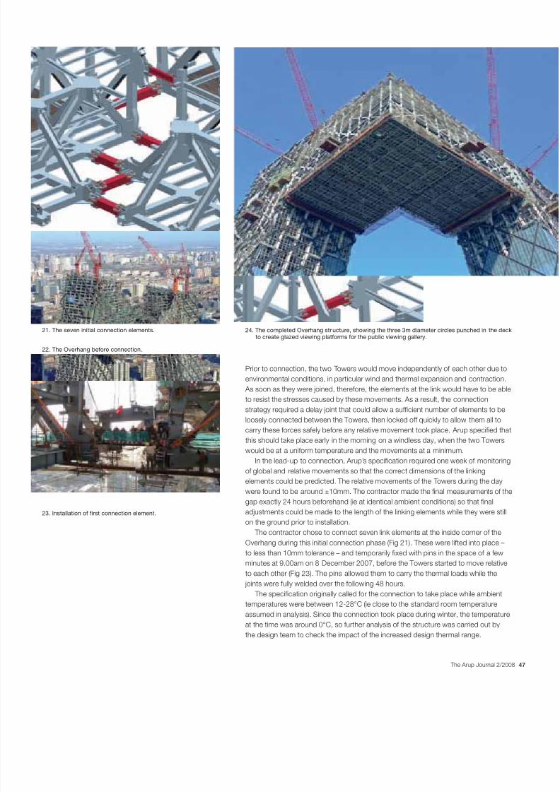
Prior to connection, the two Towers would move independently of each other due toenvironmental conditions, in particular wind and thermal expansion and contraction.As soon as they were joined, therefore, the elements at the link would have to be ableto resist the stresses caused by these movements. As a result, the connectionstrategy required a delay joint that could allow a sufcient number of elements to beloosely connected between the Towers, then locked off quickly to allow them all tocarry these forces safely before any relative movement took place. Arup specied thatthis should take place early in the morning on a windless day, when the two Towerswould be at a uniform temperature and the movements at a minimum.
In the lead-up to connection, Arup’s specication required one week of monitoringof global and relative movements so that the correct dimensions of the linkingelements could be predicted. The relative movements of the Towers during the daywere found to be around ±10mm. The contractor made the nal measurements of thegap exactly 24 hours beforehand (ie at identical ambient conditions) so that naladjustments could be made to the length of the linking elements while they were stillon the ground prior to installation.
The contractor chose to connect seven link elements at the inside corner of theOverhang during this initial connection phase (Fig 21). These were lifted into place –
to less than 10mm tolerance – and temporarily xed with pins in the space of a fewminutes at 9.00am on 8 December 2007, before the Towers started to move relativeto each other (Fig 23). The pins allowed them to carry the thermal loads while thejoints were fully welded over the following 48 hours.
The specication originally called for the connection to take place while ambienttemperatures were between 12-28°C (ie close to the standard room temperatureassumed in analysis). Since the connection took place during winter, the temperatureat the time was around 0°C, so further analysis of the structure was carried out bythe design team to check the impact of the increased design thermal range.
21. The seven initial connection elements.
22. The Overhang before connection.
23. Installation of rst connection element.
24. The completed Overhang str ucture, showing the three 3m diameter circles punched in the deckto create glazed viewing platforms for the public viewing gallery.

8/7/2019 ARUP Building the Structure
http://slidepdf.com/reader/full/arup-building-the-structure 9/12
48 The Arup Journal 2/2008
Once the initial connection was made, the remainder of the Overhang steelwork was
progressively installed. With the building now acting as one entity, the Overhang waspropping and stabilising the two Towers, and continued to attract locked-in stressesas further weight was applied. In addition to the primary steelwork elements,a continuous steel plate deck up to 20mm thick was laid down on the lowest oors of the Overhang to resist the high in-plane forces that were part of this propping action.The steel plate is not, in fact, fully continuous – three 3m diameter circles werepunched into the deck to provide glass viewing platforms for the public gallery at theOverhang’s bottom level (Fig 24).
The concrete oor slabs were only added once the entire primary structure hadbeen completed, so as to reduce the loads during the partially-constructed stage.Again, the construction stage analysis needed to take account of this sequencing.
A topping-out ceremony on 27 March 2008, on a specially-constructed platformat the corner of the Overhang, marked the completion of the steelwork installation.
Post-installation of key elements
Arup’s early analysis showed that the corner columns on the inside faces of theTowers would attract a huge amount of dead load from the Overhang, and thushave little spare capacity for resisting seismic loads. Increasing the column sizeswas rejected since they would become stiffer and hence attract even higher loads.Instead, the corner column and brace elements directly below the Overhang were leftout until the end of construction, forcing the dead loads to travel via the diagonalsdown adjacent columns and enabling the full capacity of the corner elements to beavailable for wind and seismic loads in the as-built condition.
Key elements at the intersection of the Towers and podium were also post-xedfor similar reasons. In addition, this process enabled the architectural size of theelements to be controlled, while giving the contractor additional exibility to deal withconstruction movements.
Delay joints were introduced between the Towers and the Base to allow fordifferential settlement between the two structures’ foundations. It should be notedthat over half the predicted settlements were expected to take place after the Towerswere constructed to their full height, due to the disproportionate effect of theOverhang on the forces in certain columns. These were fully closed after completionof the main structure. Further late-cast strips were also provided at several locationsaround the basement to control shrinkage.
Follow-on trades
Installing the façade began once the structure hadreached mid-height, so the façade design needed totake account of signicant movements subsequentto installation. This sequencing also created trickyinterfacing problems due to the need to share towercrane use with the steel erection, and cope with
protecting workers – and completed cladding –from work taking place above.
The lean of the Towers meant that workers on there-entrant sides of the Tower would be protectedfrom falling objects above (albeit with additionalinstallation hurdles to overcome), while extra carewould be needed to protect those on the other faceswhich were subject to higher risk.
Services installation also began while the structuwas in progress. This fast-track process was inmarked contrast to many other projects in the city, inwhich façade and MEP installation would sometimeonly start once the structure had been completed.
25. Façade build-up.
26. Construction progress at March 2008.

8/7/2019 ARUP Building the Structure
http://slidepdf.com/reader/full/arup-building-the-structure 10/12
The Arup Journal 2/2
Cutting down piles
The wide availability of unskilled labour inChina means that many operations arecarried out in a very different manner fromthe West. On CCTV, for example, piles werecut down by hand, with hammer and chisel,to expose the reinforcement (Fig 7).
While this avoided workers suffering fromVibration White Finger, a condition thatoften affects those working with vibratingmachinery like drills, this was still a verytime-consuming process, and othermethods were developed to speed thingsup. Once the outer part of the pile had beenbroken back, a notch was cut into thecentral part, and cables were tightenedaround the remainder of the section.
Then, with the help of a Tirfor winch,the mass-concrete pile top could simplybe snapped off.
Façade installation
The façade design includes large diagonal“diagrid” elements that span between eachprimary oor, mirroring the structural braces(Fig 27). These heavy pieces had to be liftedwith the tower cranes, but on the re-entrantfaces, the slope of the Towers meant that itwas impossible to get them close enough tothe edge of the oor to x them in position.The contractor came up with an ingenioussystem of supporting the element off acounterbalanced “mini-crane”, hangingon the end of the main crane cable.This allowed a team inside the Tower tomanoeuvre the piece laterally into position.
The other faces also involved challenges.The glazing panels were lifted up individuallyby rope, but on the outer faces of theTowers, men were needed on the ground topull the rope sideways to keep the panelsaway from the Tower as they were lifted, toprevent damage to glazing already installed.
Surveying
Not one of the 121 columns in either Tower’s
perimeter frame is vertical, and many of thepieces in the Base and Overhang are alignedin completely different directions. To ensureevery element was positioned correctly,the contractor continuously monitored thecontrol points throughout the building,reaching 670 in number at the most criticalstage around January 2008 after the linkingof the two Towers. Monitoring includedvertical movements of Tower circumferenceat particular oors, corner columnmovements at the Overhang soft,internal levelling, stress, raft settlement,and Overhang movement.
Reinforcement bars
Spare reinforcement is used for almosteverything on a Chinese construction shandrails for temporary staircases (andsometimes the staircases themselves);impromptu hammers and other tools; dcovers. Very few offcuts go to waste.Meanwhile, almost all reinforcement uthe permanent works is coupled ratherlapped – material costs are still the madriver in China.
Recycling
As is standard in China, virtually nothifrom the site demolition or new buildinto waste. Every brick, nail, pipe, and ptimber and reinforcement was meticulextracted and collected by a team of workers, before being used again on sisent away for reuse or recycling.
Novel construction solutions for a novel buildingThe challenge of constructing a vast, cranked, leaning building madethe contractor devise some other intriguing solutions .
27. The façade design includes large diagonal “diagrid” elements that span between each primary oor, mirroring the structural braces.

8/7/2019 ARUP Building the Structure
http://slidepdf.com/reader/full/arup-building-the-structure 11/12
50 The Arup Journal 2/2008
TVCC and the Service Building
The other buildings on site, TVCC (Fig 28) and the Service Building, were builtsimultaneously. Construction of the Service Building began in April 2006, and it washanded over in June 2008.
The Service Building was actually the critical path item, as it had to be completeand fully commissioned in advance of CCTV and TVCC. Service tunnels runningbetween the three buildings introduced a signicant element of civil engineering worksto the site.
The contract for TVCC was given to a separate contractor, Beijing UrbanConstruction Group. Work began in March 2005, and the structure was complete bySeptember 2007. TVCC and the Service Building will be described in detail in a futureissue of The Arup Journal .
Conclusion
The structure of the CCTV building was completed in May 2008, with the façade dueto be nished by the start of the Beijing Olympic Games. Within weeks of structuralcompletion, China was struck by its most violent earthquake of recent years.Although the epicentre was nearly 1000 miles from Beijing, the tremor was felt on site.Like other structures in seismic regions, CCTV is designed to resist a certain level of earthquake during construction, and no damage was reported. However, this served
as a timely reminder of the importance of the building’s rigorous seismic design andapprovals process.
That the contractor could construct such a vast and complex building with fewdelays was a credit to the design team and to CSCEC, in particular the attention paidto devising a feasible construction sequence from an early stage, and the carefulthought about the buildability of the primary structural elements and connections.
Chris Carroll is a Director of Arup in the BuildingsLondon 7 group. He led the structural design of theCCTV headquarters.
Dr Craig Gibbons is a Director of Arup in the Gulf grouand is Country Leader for the United Arab Emirates.He was the Project Manager for the CCTV headquarters.
Dr Goman Ho is a Director of Arup in the Beijing ofceHe led the structural team in the Beijing ofce for theCCTV headquarters.
Michael Kwok is a Director of Arup and leads theShanghai ofce. He was the Project Director for theCCTV headquarters.
Richard Lawson is an Associate of Arup in the BuildingLondon 7 group. He was a structural engineer for theCCTV headquarters.
Alexis Lee is a Director of Arup in the Hong Kong Bgroup. He was the acting project manager for theCCTV headquarters.
Ronald Li is a senior engineer in Arup’s Vietnamgroup. He was the Resident Engineer for the CCTVheadquarters.
Andrew Luong is an Associate of Arup in the HongKong B group. He was a structural engineer for theCCTV headquarters.
Rory McGowan is a Director of Arup China, Beijingofce. He was leader of the competition and design teamfor the CCTV headquarters.
Chas Pope is an Associate of Arup in the Beijing ofce.He was a structural engineer for the CCTV headquarters.
Credits
Client: China Central Television Architect: OMAStedebouw BV, Ole Scheeren and Rem KoolhaasStructural, MEP, geotechnical, re, and securityconsultant: Arup - Abdel Ahmed, Cecil Balmond,Carolina Bartram, Chris Carroll, Wayne Chan, Mark ChoiDean Clabrough, Paul Cross, Roy Denoon, Omar Diallo,Mimmy Dino, Xiaonian Duan, Gary Ge, Craig Gibbons,Sam Hatch, Colin Ho, Goman Ho, Jonathan Kerry,Michael Kwok, Richard Lawson, Alexis Lee, Jing-Yu Li,Ronald Li, Zhao-Fan Li, Peng Liu, Man-Kit Luk, AndrewLuong, John McArthur, Rory McGowan, Hamish Nevile,Jack Pappin, Steve Peet, Dan Pook, Chas Pope, AndrewSmith, Stuart Smith, Alex To, Felix Tong, Paul Tonkin,Ben Urick, Bai-Qian Wan, Yang Wang, Yi-Hua Wang,Will Whitby, Robin Wilkinson, Michelle Wong, StellaWong, Eric Wu, Lucy Xu, Angela Yeung, Terence Yip,George Zhao (geotechnical, structural) Main contractorChina State Construction Engineering CorporationSteelwork contractors: Grand Tower; Jiangsu HuningSteel Construction logistics: Turner ConstructionBuilding movement monitor: China Academy of BuildiResearch Presetting analyst: Tsinghua UniversityIndependent site supervisor: Yuanda InternationalIllustrations: 1, 2, 25 OMA; 3, 6, 10, 17 Nigel Whale;4, 12, 14, 16, 19, 23, 27, 29 Chas Pope; 5, 8, 18 Arup;7, 9, 11, 13, 15, 20 Rory McGowan; 21 CSCEC; 22, 24,26, 28 ©Arup/Frank P Palmer.
References
(1) CARROLL, C, et al . CCTV Headquarters, Beijing, China:Structural engineering design and approvals. The Arup Journ40 (2), pp3-9, 2/2005.
(2) GREEN, G, et al . CCTV Headquarters, Beijing, China:Services engineering design. The Arup Journal , 40 (3), pp223/2005.
28. The TVCC building, to the left of the CCTV headquarters, April 2008.
8/7/2019 ARUP Building the Structure
http://slidepdf.com/reader/full/arup-building-the-structure 12/12
The Arup Journal 2/2
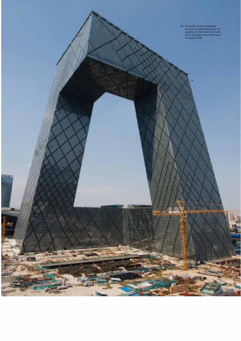
29. The scale of the completedstructure is emphasised by thequantity of site works that werestill in progress around its basein August 2008.