artillery - fort sill | oklahoma · 2018-02-16 · artillery as it has heretofore been evolved...
TRANSCRIPT

ARTILLERY TRENDS
APRIL 1965
US ARMY ARTILLERY AND
MISSILE SCHOOL

Instructional Aid Number 33
● COVER
Fire support coordination, Little John operations, target acquisition, RSOP, aerial rocket artillery, and logistical support—in the air assault style. This issue provides an insight into air assault division artillery operations with Firepower Plus Mobility on page 5. The alphabetical index for 1964 ARTILLERY TRENDS begins on page 62.
● ARTICLES USAAMS Extension Courses Provide Many Benefits .................. 2 LASER Rangefinder ...................................................................... 3 Firepower Plus Mobility—The Role of
Air Assault Division Artillery .................................................... 5 Artillery in The Desert ................................................................... 44 Why Single Sideband..................................................................... 47 No Compromise............................................................................. 52 Performance ═ Standards............................................................... 59 Alphabetical Index for 1964 .......................................................... 62
● NEWSNOTES News of, for and about The Artillery World................................... 68 Readers' Comments........................................................................ 69
● RESIDENT COURSES U.S. Army Artillery and Missile School Resident Courses............ 71
● STATUS OF TRAINING LITERATURE AND FILMS Training Literature ......................................................................... 78 Training Films................................................................................ 79
ARTILLERY TRENDS is a publication of the United States Army Artillery and Missile School appearing only when sufficient material of instructional nature can be gathered.
1

USAAMS EXTENSION COURSES PROVIDE MANY BENEFITS
The extension course program of the U.S. Army Artillery and Missile School provides progressive artillery instruction for personnel of all components of the Army. This instruction is administered to individual students by correspondence means at no cost to the student. A particular advantage of this means of self-education is that the student may select his own course of study which he can complete at a time and place of his own choosing. The principle of correspondence study has long been recognized by leading educators as an effective means of obtaining an education and, in recent years, has been adopted by some of the leading industrial firms as an efficient method of increasing individual job proficiency.
The field artillery extension course program presents career type extension courses which parallel corresponding resident courses and which will provide basic and advanced branch level training. The advanced level (career) extension courses also are parallel to the Artillery USAR School career course to the extent that reciprocal credit may be granted between the two, without penalizing the student on his transfer from one to the other. Special extension courses are also offered which will provide comprehensive instruction in specific subject areas such as gunnery, communication, survey, etc.
The field artillery extension course program provides many benefits for both active army and Reserve Component personnel. The career type extension courses permit officers of all components to obtain credit for basic or advanced branch level training, as well as artillery branch qualification for officers transferred into the artillery from another branch. Additionally, Reserve Component officers may meet educational requirements for promotion and receive point credit for retirement at the rate of one retirement point for each three credit hours of extension course work successfully completed. Officers and enlisted men of all components may also increase their job proficiency through the study of special extension courses, and enlisted men may utilize certain recommended selected subcourses to assist in preparation for MOS evaluation tests.
These benefits will only accrue, however, if the individual plans his study schedule carefully and follows this planned schedule to the letter. The objective of a reasonable study schedule should envision the completion of three credit hours each two weeks throughout the year. Strict adherence to this type of schedule would enable the student to meet minimum progress requirements without difficulty. It is incumbent on all military personnel to continually improve their military knowledge. Thus, the artillery extension course program should be carefully considered as an excellent and economical means of obtaining and maintaining their military education.
2

LASER RANGEFINDER results of USAARTYBD tests
Results of LASER rangefinder service tests by the U.S. Army Artillery Board (USAARTYBD) conclusively show that targets can be located to a degree of accuracy exceeding that which is necessary for surprise fire for effect. In a coordinated effort to achieve an Army-wide LASER (fig 1) rangefinder end item, the U.S. Army Artillery Board, the Infantry Board, and the Armor Board tested two versions of LASER (Light Amplification by the Stimulated Emission of Radiation)—the XM23 and the XE-6. Both rangefinders were designed to provide the forward observer with precise target location data including range in meters and, after leveling and orientation, vertical angle and azimuth in mils.
Results of tests performed by the U.S. Army Infantry Board and the U.S. Army Armor Board, concerned chiefly with mortar and direct fire applications were reported to the USAARTYBD. Infantry and armor test results demonstrated that the maximum effective ranges of direct fire weapons were significantly increased. The rangefinders were capable of precisely locating personnel, vehicles, smoke, trees, bushes, and other natural and man-made features.
The principle of operation was the same for both rangefinders and was very simple. A high energy pulse of electromagnetic energy in the form of red light is generated by a LASER cavity containing a synthetic ruby rod.* A range-counter starts running when the pulse of light is generated. When this light is reflected back from the target at which it was aimed, the range-counter stops and provides a readout of the rangefinder-target distance in meters.
* Only one pulse is used per ranging, and this pulse is only about 25 billionths of a second duration.
Figure 1. Front Panel View—LASER (XM23).
3

Surveillance and target acquisition were accomplished by the telescope integral to the rangefinder. Once identified, a 1-mil reticle in the telescope was placed over all or part of the target. Generation of the LASER pulse and the entire ranging process were then accomplished within a few seconds.
Since the transmitted pulse is only about 1 mil wide and high, it was essential that the 1-mil reticle sight be placed, directly over the target. This extremely narrow beamwidth afforded the advantage of little or no clutter returns from objects in the vicinity of the target. The narrow beamwidth requires the rangefinder to be tripod-mounted for stability. Horizontal and vertical scales permitted rapid measurement of azimuth and vertical angles.
The capability of surprise fire for effect, using an observer's polar plot information, presupposes, of course, that the fire direction center (FDC) knows the location of the observer. The LASER rangefinder allows the observer to very accurately find his position. Using self-survey techniques of two-point resection, traverse, and one-point resection, in decreasing order of acceptability, rapid and accurate self-location was provided.
After the observer reported the distances and required angles to two known points, the FDC not only accurately located the observer but also reported to the observer an observer-known point azimuth to a degree of accuracy far exceeding that of conventional magnetic compasses. The observer could then orient his tripod-mounted rangefinder with an accurate azimuth.
Limited traverse was also performed using the LASER rangefinder. If the number of legs was held to a minimum, accuracy in location and azimuth suitable for forward observer use was realized. One-point resection is dependent for accuracy upon the M2 compass and all the attendant magnetic anomalies.
The entry of LASER rangefinders into the field will greatly enhance the artillery, armor, and infantry first round fire for effect capability. Additionally, a large reduction in logistic support requirements may be realized because of the ammunition saved by not adjusting fires; for example, assume that a total of six rounds are expended in adjustment on a target, and 18 rounds are expended in fire for effect by a unit which has registered but which does not have a LASER rangefinder. The addition of a LASER rangefinder would have resulted in a 25 per cent ammunition savings as well as surprise fire for effect.
The capability for planned fires is significantly improved by the introduction of a LASER rangefinder. Fence lines, avenues of approach, or suspected enemy OPs can be rapidly and accurately ranged upon, and precise target locations can be sent to the FDC without the necessity of check point registrations. Additionally, the forward observer in the attack can rapidly and accurately survey in points along the expected avenue of attack. The FO can then call for surprise fire for effect on these points or, using his LASER rangefinder, shift from such points and call for surprise fire for effect on targets of opportunity.
4

THE ROLE OF
AIR ASSAULT
DIVISION ARTILLERY 5
A BOLD NEW LOOK Colonel William A. Becker
Commanding Officer 11th Air Assault Division Artillery
"Take a bold new look at land warfare mobility." This statement was the charge to the Army Tactical Mobility Requirements Board appointed by Defense Secretary McNamara in 1962 and headed by General Hamilton Howze. Take a bold new look they did—and proposed bold new concepts.
To develop and test some of these concepts, in February 1963, the 11th Air Assault Division and the 10th Air Transport Brigade were activated, with station at Fort Benning. Since then, an intensive program of testing, development, and refinement of tactics, techniques, and concepts has been conducted in the field and on the drawing board. Formal army testing was concluded with AIR ASSAULT II, a two-division size maneuver held in the Carolinas during September-November 1964.
The articles that appear in this issue of ARTILLERY TRENDS were submitted by members of the 11th Air Assault Division Artillery team during the testing period. The articles serve not only to chronicle experiences gained and the tactics and techniques evolved during the Air Assault experiment but also—in recognition of the fact that much has yet to be added to the body of knowledge peculiar to the support of air assault operations—to stimulate independent minds to further development of air assault tactics and techniques.
To focus properly on the more detailed articles that follow, a broad consideration of the innovations and differences between air assault artillery and artillery as it has heretofore been evolved would be of some help.
The most obvious difference is one of organization of the division artillery, particularly the inclusion of an aerial rocket artillery battalion and an aviation battery.
The unusual capabilities of the aerial rocket artillery are quick reaction, close-in effectiveness, and selectivity of fires—all of which are essential to the proper support of an air assault by the infantry. The aviation battery of division artillery provides command, liaison, and observation aircraft for all artillery units. (Ground vehicles seldom can be used to accomplish these functions.)
There are several other significant differences which pertain to air assault division artillery:
● Fire Support Coordination. While the principles of fire support coordination remain common to all divisions, it becomes a more complex function in the air assault division owing to the addition of aerial firepower means and to the sheer numbers of aircraft—about 400—that must travel the airspace through which artillery projectiles and aerial weapons craft also travel en route to targets. It should be noted that the air assault division requires more tactical air support than other divisions, principally because it covers more territory and finds more targets.
6

Figure 1. Organizational chart—air assault division artillery. ● Target Information. With several hundred aircraft in the air in the
course of a day of operations, the air assault division acquires a tremendous amount of target information. It is a principal task of division artillery to put this information to use for shooting purposes. Of particular urgency are enemy air defense weapons which constitute a considerable threat to the division's mobility; also, opposing armor must be attacked by fire before it can maneuver against relatively dispersed elements on the ground, and enemy mortar and artillery units must be neutralized before they can bring concentrations of fire on our pickup zones and aircraft laager areas. Target information must go direct to the user or be processed swiftly and accurately to insure success.
● Mobility. All units of the division artillery are air-transportable by aircraft available to the division—the CH-47 (Chinook), the UH-1 (Iroquois), or CV-2 (Caribou). However, ground mobility is limited. To mobilize elements on the ground, if necessary, resources from without the division are secured.
● Security. When the division is operating in enemy rear areas, its organic artillery support is probably more essential than at other times, for division units will operate out of range of corps artillery. In such situations division artillery units will be exposed to enemy action. This was experienced by artillery units opposing the Japanese in World War II and frequently during the Korean conflict. In such situations, air assault artillery units employ well established measures; additionally, they have some distinct new advantages. They can be airlifted into position areas which are relatively inaccessible to the enemy and are not exposed en route to enemy ground action. Units can be quickly lifted out of position if a threat approaches, or air assault infantry (on alert
7

with their lift) can react quickly to assist a seriously threatened artillery unit. ● Survey. Air assault artillery units move so far and so frequently
that complete division artillery surveys usually are not achieved with current means. Thus, the needs of Little John units are concentrated on, together with other high priority requirements. Several approaches to airmobile survey are being experimented with to seek a good solution pending development of the Long Range Survey System (LRSS) and the Visual Airborne Target Location System (VATLS).
● Artillery tactics. Artillery tactics are shaping up to be somewhat different from those which are familiar to us all. Direct aerial firepower is concentrated in preparatory and close-in fires during assaults to maximize its distinct effectiveness. Ground artillery units, while frequently used in preparations and in their usual close-support role, are essential to provide needed support at night and in extremely bad weather. Artillery units frequently are emplaced in enemy territory for special, short-duration missions and then are withdrawn by air.
While the air assault artillery units of this division have operated with confidence and skill in the development of the concept and in the collation of basic practical knowledge, much remains to be done. Accumulation and early publication of the knowledge gained may be useful in meeting the needs of tomorrow's airmobile artillery. We trust that the articles herein on air assault artillery constitute a recognizable stride toward that end.
The techniques and procedures expressed in the following air assault articles are not accepted Army concepts, but they are the means by which the air assault division artillery accomplished its assigned mission—that of testing the air assault concept.
OPERATION REACT Major William R. Hendrickson
6th Battalion, 81st Artillery It was 0430 hours. The air was filled with the whine of jet engines and
the powerful rotor wash of CH-47 (Chinook) helicopters. The first aircraft took off with the Battery C commander and his advance party. Six more Chinooks, loaded with howitzers, rose in the gloom and hovered, one by one, to pick up sling loads of ammunition, then moved off to the north. Another two Chinooks followed with a Little John launcher section and a survey party. The last Chinook waited for the hook-up crews to board, then hastened off after the others. At 0435 hours the woods were once again still and dark—only the coffee and bacon aroma lingered.
Operation REACT (fig 2) was underway—a coordinated attack of three infantry battalions against an enemy regimental command post. The 1st Brigade of the 11th Air Assault Division, in division reserve 100 km from the objective, had been committed to break-up an aggressor penetration
8

Figure 2. Area of operations for Operation REACT.
on the corps flank. The 6/81 Artillery, in general support, was attached to the 1st Brigade for the deep assault. H-Hour was 0630. One infantry battalion made a helicopter assault at 0230 and established blocking positions to prevent the enemy from withdrawing or reinforcing.
At 0500, 60 kilometers from his starting point, the battery commander jumped from the lead Chinook as it touched down and quickly pointed out howitzer positions to his chiefs of section who ran behind him. The battery FDC vehicle and equipment roared down the ramp of the aircraft and rushed to the designated spot in the woods. The lead Chinook departed just as the main air column was sighted.
Pathfinders, who had parachuted into the area during the night, expertly guided the aircraft into position. After the sling loads of ammunition had been positioned, the Chinooks landed and discharged their howitzers, "mules" (lightweight air transportable weapons carriers) Little John launcher and missile, and men. The Little John section moved to a hide area and started surveying for a nonnuclear mission. The 105-mm howitzer battery executive officer reported the battery ready to fire at 0512 and commenced firing in support of the infantry.
This occupation of position was routine for the Sky Soldiers of the 6th Battalion, 81st Artillery. The battery commander's reconnaissance consisted of one pass over the position area the afternoon before in a light observation helicopter. His selection of this particular position was based not only on the normal considerations but also on the capacity of this position to land 10 Chinooks simultaneously at night. When he returned from his reconnaissance, the battery commander met with the Chinook flight leader to coordinate the movement. A call was made to the Pathfinder Detachment for a team to parachute into the landing zone
9
at 0200. Pathfinders were needed to set up landing and warning lights and a radio beacon to guide in the aircraft. Fire support was needed to protect the Pathfinders and the battery during the occupation of position. A platoon of aerial rocket artillery helicopters (UH-1B) rendezvoused with the Chinook column at the designated release point and searched the surrounding area while the battery was landing, maintaining continuous radio contact with the howitzer battery commander.
The action continued with the movement of the second battery at 0600. The same number of aircraft were used and the route was the same, but the landing operation was different. Eight Chinooks landed simultaneously at precise locations so that the howitzers, when unloaded, described a "Lazy W" battery formation. At 0630, as the last helicopter took off, the battery was layed and ready to fire to support the three-pronged assault.
Battery B occupied its position without a single man on the ground to assist in landing the aircraft. The battery commander conducted his reconnaissance by helicopter the day before, after a briefing by the Battery C commander who recommended position areas he might have selected were he not making a night occupation. En route to the general area, the Battery B commander made a thorough map reconnaissance. As he approached his tentatively selected position he started sketching, filling in more details as he progressed. By the time he flew over and passed the location he had a fairly complete sketch which was later improved after debriefing the pilot. Now he started looking for alternate positions—and sketching them. As he was returning to his battery, the Battery A commander, en route to the same area in another OH-13, called on the radio and asked for position area recommendations for his battery.
The remainder of the battalion, Battery A, and the battalion FDC/Operations, began moving with 12 Chinooks at 0700, the Battery A commander 3 minutes ahead with his advance party. Ground guides were positioned to direct the incoming traffic; all vehicle loads landed on the left flank of the battery. Battalion FDC personnel and equipment moved to a concealed position on high ground within the Battery A perimeter. All elements were closed and operational, with radio communications established with all higher, lower, and supported units by 0748.
The survey section set up a master station and conducted a simultaneous observation to establish a common direction (one survey instrument operator accompanies each battery). Traverse to the batteries was out of the question; the battalion was spread over 5,000 meters—in enemy territory.
At 0800, when Battery A completed its registration, all data necessary to construct a battalion observed firing chart was available. The S4 arranged with the forward support element of the division support command for direct delivery of water, fuel, and rations by helicopter to each battery and ammunition by CV-2 (Caribou) using the low level extraction method (LOLEX).
10

Most of the planning and coordination for this operation was accomplished over FM radio, at distances over 50 kilometers, with extensive use of brevity codes and specially developed message forms. Detailed SOPs were prepared and exchanged between artillery, infantry, and aviation units, and close working relationships were established. Even though the artillery battalion was in general support 50 kilometers distant from the infantry brigade in reserve, the coordination for the assault and the transition to attached status was accomplished smoothly with less than 3 minutes of radio transmission.
Through the use of helicopters to accomplish the movement, the battalion was able to maintain close and continuous fire support when and where needed.
Brigade Fire Support Coordination Lieutenant Colonel Lloyd J. Picou
1st Battalion, 15th Artillery The Sky Soldiers of the air assault division are blessed with a greater
variety of fire support and fire support means than ever have been available to any other combat unit. For instance, an air assault landing usually is preceeded by tactical air command (TAC) air strikes, a tube artillery preparation, a preparation by aerial rocket artillery (ARA), and final suppressive fires by armed escort helicopters.
Providing artillery support to far ranging Sky Soldiers of the air assault brigades and battalions is a challenge to the artilleryman. More important is the coordination of all the fire support means. This is the job of the direct support artillery battalion commander who normally is the fire support coordinator for the brigade. The purpose of this article is to explain how this job is accomplished.
In discharging his duties as fire support coordinator, the direct support battalion commander has the easiest part in solving the problem. He decides how best to support the operation, where and when to position his battalion, and how much support to request from higher headquarters; all normal operations in any division. From this point, the liaison officers at brigade and battalion level compile their target lists and submit their plans and requests to the artillery operations section. The final result is the artillery fire plan. In most instances, in the past, the plan has been all important. Once is was "jelled," it was merely a matter of reading the script and following the scenario. In the air assault division, the plan is only the beginning. There are too many imponderables, and plans, as written, often cannot be followed. The assault usually takes place miles away in the enemy rear area. There is little advance intelligence on targets in the objective area. Communications
11
are limited to radios. There is also the matter of aircraft from as many as nine different agencies flying around and in the airspace over the objective area. This is the crux of the fire support problem—the actual coordination of support means once the air assault is under way. The person who controls and coordinates the fire support means is the liaison officer with the maneuver battalion. He is the most important cog in the machine, and he had better know his business. In fact, he is just about the most important artilleryman up to brigade level. The integration and coordination of all fire support means is his job once the action has started, and artillery is judged from the results of his performance. This is the big difference in fire support coordination in the air assault division. With this in mind, let's look at the duties of the liaison officer, first to examine what he must accomplish during the planning for an operation and second, to see what he must do to control fire support during the execution phase.
There is no need to go into great detail concerning the planning accomplished by a liaison officer for an air assault operation. Let it suffice to say that he accomplishes the normal duties of an artillery liaison officer in any division. He works with the infantry battalion S3 in the development of the plan, he advises him on the employment of artillery, he develops the normal fire plan to support the operation, and he insures that fire support will be rendered when needed. However, there are two areas that are peculiar to air assault fire planning: first, the liaison officer must be qualified to integrate the many fire support means available to him into the plan, and second, due to the speed which characterizes air assaults, operations are of relatively short duration. Therefore, it is essential that the liaison officer make an accurate estimate of the amount and type of fire support needed for an operation, since the operation may be over before additional fire support means can be brought forward to influence the action.
Perhaps the most important and difficult part of the liaison officer's job is the actual coordination and integration of the fire support means during the operation. The liaison officer normally rides in the aerial tactical operations center (TOC) with the task force commander. From this vantage point, he directs the various fire support means available to him. These normally include one or more artillery batteries and forward observers, one aerial rocket artillery (ARA) battery consisting of 12 ships, and a number of high performance aircraft from TAC air. Additional fire support, including that of the Little John battalion, is available from division artillery should any particular operation require it. Regardless of the amount of fire support made available to the liaison officer, all is placed on "his radio net" for control within the sector of supported units.
There are many variables in an air assault operation. To the artillery liaison officer, timing of the operation is probably the most important single variable with which he must be concerned. In actuality, the execution of the fire support plan is initiated by the battalion liaison officer in each infantry battalion sector. To understand the importance of timing to the liaison officer and to give an insight into the tasks that the battalion
12

Figure 3. BRIGADE MISSION: Brigade assault with two battalions to
secure the bridges at sites 4 and 4A, secure a safe base of operations in the vicinity of Objective 21, conduct air assaults to destroy aggressor in zone, and prevent the aggressor from reinforcing to the west.
liaison officer must accomplish throughout the assault phase of an operation, consider the following hypothetical situation (fig 3).
Assume that the planning phase for the operation has been completed and that the assault phase is about ready to commence. Listen to the radio conversation of the liaison officer with the 2d infantry battalion (simple codes are used for security reasons). TIME FROM TO MESSAGE H—25 LO S3 Infantry battalion will lift off in 3
minutes. S3 LO Division artillery reports a Hawk unit
vicinity 020671. Cavalry reports minor activity vicinity Objective 20, 21, 22, Aggressor build up vicinity Objective 23.
H—24 LO TAC AIR Commence preparation fires at H—20 on concentration #254, 255, and 256, be clear of the objective areas by H—10.
H—23 LO MOHAWKS TAC air will be on schedule, you will be clear to enter objective area at H—10. There is a Hawk unit vicinity coordinates 020671. Report as you see our column approach the IP.
H—23 LO ARA Send one platoon to coordinates 020671, Hawk unit, concentration #287. You will follow Mohawk into Objective area at H—6. Fire concentration number 257 and 258 as scheduled.
13

TIME FROM TO MESSAGE H—22 LO S3 Am airborne. S3 LO Cavalry reports engineer unit working
at bridge site 4. Negative action at sites 2, 3, and 4A. Armor column moving toward bridge 4 about 5 miles east of bridge. Artillery battalion will lift off at H—20, ready to fire at H+05 minutes.
H—21 LO TAC AIR Armor column vicinity coordinates 094885 moving west, concentration number 288.
H—20 TAC LO Striking concentrations 254, 255, and 256. Will proceed to orbit point Delta at H—10.
LO S3 Infantry Battalion crossing IP. S3 LO Division artillery reports that cavalry
elements will be diverted from screening mission your sector at H+1 hour.
LO MOHAWKS Do you have us in sight? MOHAWKS LO Just joining your column now. , Do
you have any answer from ARA on Hawk unit?
LO ARA What is the status of concentration 287?
ARA LO Target confirmed, will have surveillance in 01.
LO MOHAWK Did you monitor? MOHAWK LO Roger out. H—19 ARA LO Concentration 287 one missile
launcher destroyed, one radar destroyed, estimate 15 casualties.
H—18 LO S3 Crossing Air Control Point (ACP). H—16 LO S3 Crossing ACP 2. H—14 TAC AIR LO Tank column neutralized, 2 tanks
burning, 3 others turning back. H—11 LO S3 Infantry battalion crossing landing
zone release point (LRP). LO TAC AIR Are you clear of objective area? TAC AIR LO Roger. At point Delta. H—10 LO MOHAWK Area clear to enter. Maintain
surveillance from site 4A to site 3. LO ARA Clear to fire preparation in 03. ARA LO Fire mission, coordinates 886745
Infantry platoon, request permission to fire.
14

TIME FROM TO MESSAGE LO ARA Negative—it's not in our zone—Wait! LO S3 Check coordinates 886745. Infantry
platoon. S3 LO Coordinates 886745 clear of friendly
troops. H—10 LO ARA Permission to fire granted coordinates
886745 concentration 289. H—6 ARA LO Firing concentrations 257 and 258. H—5 ARA LO Concentrations 257 and 258 targets
neutralized, estimate 3 APC's damaged, 40 casualties.
H—2 FOI S3 Fire mission coordinates 971688 azimuth 0200 road block/will adjust.
LO ARA, FO1 ARA your mission, FO1, you control. LO FO2 and FO3 Advise commanders of this road
block. H—1 CAV INF S-3
to LO Fire mission, artillery battery moving
on road toward site 4, vicinity coordinates 062697.
LO TAC AIR Artillery battery moving on road toward site 4 from the East, concentration 291.
H FOI LO Coordinates 970685 negative contact. FO3 LO Coordinates 985698 moving toward
Objective 23. H+1 FO2 LO Coordinates 992679. Moving east.
Encountering light resistance. H+3 FO3 LO Fire mission, coordinates 988689
azimuth 1840 infantry platoon dug in, will adjust.
LO ARA Your mission concentration 293, FO3 control.
This has been a brief run-down of what one liaison officer might do from lift-off to H+3 minutes. The volume of radio traffic will be directly proportional to the number of targets located in the objective area. Here has been shown only a sample of the type transmissions, the decisions and coordination that he must make. For obvious reasons, most of the communications he would have with the liaison officer at brigade and the artillery battalion headquarters have been eliminated. Additionally, consider that while this LO is accomplishing his mission the liaison officers with brigade and the other maneuver battalions are doing much the same.
It can be seen readily why the liaison officer plays such an important role. Always staying alongside the task force commander, he keeps abreast of the situation as it develops and immediately directs some form of fire support where needed. He is the vital link in this combined
15

arms team. The artillery liaison officer can be likened to an organist pressing keys and pulling stops while playing a musical score. The liaison officer must play each note at precisely the right moment, for unlike the organist whose discordant note may make the listener wince, the liaison officer's mistake may bring swift and sure disaster to an operation. On the other hand, if the liaison officer plays his role properly, he will achieve the harmonious blend of fire support necessary for success.
Something Different About Little John
Lieutenant Colonel Charles F. Farber 2d Battalion, 42d Artillery
"Scoot, shoot, and scoot" is a principle put into practice continuously by members of the 2d Battalion (Little John), 42d Artillery. As a matter of fact, the battalion has "scooted, shot, and scooted" in and out of so many different locations and so many different situations that it has gained a whole new perspective as to the role it can and does play in air assault operations.
In the division artillery, the problems of reaction time and mobility are paramount. A flexible and versatile artillery unit, the Little John battalion has accomplished a variety of assigned missions. The tactical employment of the unit has assured acceptance and accomplishment of firing missions in both attack and retrograde operations over a division front of some 70 miles. At other times, it penetrates deep into enemy territory to accomplish special missions (fig 4).
During one maneuver phase, a lucrative target was located and a two-round fire mission was assigned to the battalion. To accomplish the mission, it was necessary to move to a firing point approximately 24 km inside enemy territory. This was done by using six UH-1D helicopters and sling-loading equipment. The mission was completed without detection by the enemy, and the elements involved "scooted" back to friendly territory as soon as the mission was completed.
In another instance, an area well populated with enemy forces was the target. A comprehensive map reconnaissance was made, and a UH-1D was dispatched with a reconnaissance officer and a survey party to select and survey possible firing positions. By flying a route selected to deceive the enemy, the survey party finished its job well before TOT time. Shortly before the time of firing, a launcher section moved by CH-47 helicopter into the selected firing position, quickly prepared for action and fired the Little John rocket on schedule.
To accomplish its assigned missions, the battalion utilized both helicopters (fig 5) (CH-47s for internal loading and UH-1Ds for external loading) and organic jeep transportation to get from battery hide areas (fig 5) to firing points. When these firing points were in enemy controlled areas, air movement, employing deceptive tactics, was used exclusively.
16

One of the biggest problems for the Little John battalion in the air assault concept is security. A potential enemy will probably know that the Little John carries the "big punch" of the division artillery and will spare no effort to find and destroy this threat to his operations. However, with the skillful selection of hide areas (fig 6) and firing points, strict observance of camouflage discipline, deception, and frequent moves, the Little John battalion can be a very elusive quarry. To preclude detection, reconnaissance and survey of possible firing points is continuous; for example, during one five-day maneuver, 35 firing points and 14 hide areas were selected and surveyed for possible use. Additionally,
Figure 4. The attached schematic diagram shows the employment of the Little John firing section(s). Upon receipt of a fire mission, the firing section moves by organic transportation from the battery hide area to the battery pickup zone (PZ), approximately 500 to 1,000 meters away. At the battery PZ, the firing section and the CH-47 helicopter rendezvous, and the section is air-lifted to the firing point LZ. From this LZ, the CH-47 flies to the laager area to await the firing section while the section travels by organic transportation to the firing point (500-1,000 meters away). Upon completion of the fire mission, the section travels by its own organic transportation to the laager area where it again meets the CH-47 and is air-lifted back into the battery landing zone. Here the CH-47 is released, and the section returns to the battery hide area by an alternate route, if possible. It should be noted that, if time becomes extremely critical and the target is within range, firing may be accomplished from the hide positions. An immediate displacement of the entire battery would be required.
17

Figure 5. Unloading Little John from CH-47A (left). Preparing Little
John in hide area (right) (photos by L and K Photo Shop). aircraft landing and pickup zones were selected 500 to 1,000 meters from position areas, and ground movement to pickup and landing zones was always by covered route. As additional precautions, aircraft were moved to laager areas upon completion of off-loading of personnel and equipment, and preselected pick-up points were always utilized in connection with deployment to and from selected firing points.
Another major problem for the Little John battalion was logistics. However, a solution was found by resupplying rockets directly from the SASP by air to preselected points. Rockets were mated and placed on carts at the SASP and then picked up by a unit assembly and transport
Figure 6. Schematic of firing battery hide area.
18

section at the preselected location. Ammunition was requested through command channels as each rocket was expended.
The organization of the Little John battalion in the air assault division is unlike that of conventional Little John units. Included in the organization are a headquarters, headquarters and service battery (HH&S) and three firing batteries. HH&S battery includes a met section (capable of producing both electronic and visual met data), three survey teams, and other normal headquarters agencies. Its strength is 12 officers, two warrant officers, and 98 enlisted personnel. Each of the three firing batteries is authorized four M34 launchers and allied equipment and 11 1/4-ton vehicles for use as prime movers and communications vehicles. Each firing battery has a headquarters, two firing platoons, two assembly and transport sections, and an authorized strength of six officers and 82 enlisted men.
There is always a requirement for new ways to increase efficiency of operations at the firing point where every minute is critical. To accomplish this, new ideas are sought and tested. One such recently tested idea improved the method for erecting the AN/PMQ-6 windset (fig 7). The system reduces required time by approximately one-half. The windset mast is mounted on a false front bumper on the M151 jeep and tilted back between the driver and assistant driver when in traveling position. The jeep is moved to the windset position and the mast is lifted to an upright position. The jeep acts as the legs of the windset, and the mast is leveled by use of two jacks attached to the ends of the false bumper. As the mast is leveled, it is raised by using a compressed air bottle rather than the usual hand pump. Only three guy ropes are required due to the increased rigidity of the base. This is only one of the methods devised to reach the goal of 10 minutes or less from the time the unit reaches a firing point to "on the way."
Figure 7. Windset mast mounted.
The Little John battalion has demonstrated its adaptability and value to the air assault concept The coupling of proven techniques with the ingenuity of battalion personnel has made it possible to provide the Sky Soldiers with a reliable, lightweight, helicopter transportable, special ammunition delivery means.
19

Aerial Rocket Artillery
Captain Robert W. Arnold Captain Ira E. Greeley, and
Captain Lawrence O. Zittrain 3d Battalion, 377th Artillery
In the aerial rocket artillery (ARA) battalion, the objective is to deliver timely aerial artillery fires throughout the area of operations and to respond rapidly to any tactical mission that might be assigned. In furtherance of these objectives, SOPs have been developed that have proved to be successful in application. They are modified as necessary to cope with new problems encountered on maneuvers. The following paragraphs will discuss problems encountered and aerial artillery operations.
FIRE MISSION RESPONSE To provide rapid response, each battery designates an alert platoon with the
crews waiting in or near the aircraft which have been untied and preflighted. The platoon or section leader monitors his radio or telephone at the aircraft for fire missions. When an aerial artillery battery receives a fire mission, the "alert" platoon or section is normally airborne within 2 minutes and en route toward the target.
Upon receipt of "Fire Mission," the aircraft are started and run up, and checks are made while the platoon or section leader copies the mission. The format differs slightly from the standard artillery fire mission in that only the essentials of target location, direction of movement (if a moving target), and a brief target description are given initially. An innovation has been added by the battery operations providing a heading and time to target computed while plotting the target. This allows the aircraft to proceed immediately toward the target without wasting valuable seconds finding the proper maps, plotting the location, and determining the correct heading prior to take-off. The platoon or section leader, while en route plots the target, plans the attack, and gives his fire commands.
To reduce response time, the following factors are considered: ● Location of fire units. Response time is reduced by positioning ARA as
close to the target area as the situation permits. ● Pre-positioning of fuel and ammunition. This also reduces response
time by allowing aircraft to be refueled and rearmed at positions as close to objective areas as security permits.
● Direct lines of communication between supported and supporting units. Considerable time is consumed when fire mission requests are relayed through various headquarters prior to reaching the unit to deliver
20

the fires. Therefore, whenever practicable, the missions of reinforcing or general support-reinforcing are assigned to provide a quick fire channel for the supported unit.
EN ROUTE PROCEDURES To avoid detection en route and reduce exposure time to ground fire and
air defense units, aircraft are flown in the "nap of the earth" with altitudes of 50 feet seeming like outer space. Through proper training and an alert attitude the threat of striking unseen wires can be reduced to a minimum. Flying at this low level greatly increases the problem of navigation, particularly when over great expanses of flat wooded area. DECCA, an electro-mechanical system graphically displaying the aircraft's position, proves to be of little value on short range flights because of the time delay in orienting and checking for accuracy. DECCA is used as a means to navigate to the objective area. The ability to navigate to and sometimes below tree-top level is a must for air assault operations and increases as a direct function of training and practice. Accurate map reading combined with use of a pre-selected course to the target area for a computed time (dead reckoning) proves to be the method most practical, accurate, and successful, for en route navigation. The flight, regardless of the number of aircraft involved, normally is in an echelon formation en route so as to avoid more than one aircraft passing over the same point. It becomes the flight leader's responsibility to insure that all aircraft in his flight are advised of en-route obstacles.
ATTACK TECHNIQUES With a platoon or section attacking a target from a single direction, one of
two formations is used depending on the target's disposition. The first, employed primarily against a linear type target, is a formation of aircraft in column or "trail" with about 800 meters between aircraft. With all aircraft attacking parallel to the long axis of the target, a separation is necessary to allow each aircraft to fire and break off before the succeeding aircraft initiate firing. Frequently the aerial rocket artillery is given fire missions against convoys on roads where this formation is the only one that provides the desired degree of effectiveness because of high trees on either side of the road. No precise range or deflection probable errors have been established for the M3 rocket system because of uncontrollable variables such as air currents and gust effects. However, the range spread is greater than is deflection; thus, the trail formation is more effective against a ground column than the second attack formation of line or "spread." In the spread formation, all aircraft come up on a line running perpendicular to the direction of attack. Normally used against area type targets, this formation has the advantage of permitting all aircraft to fire simultaneously and to maximize the volume of fire and surprise. Each aircraft, depending on its position in the formation, is assigned a corresponding portion of the target, much like individual howitzers firing a deflection spread. A disadvantage of the formation is the loss in aircraft maneuverability in the event of any weapon system being forced to break off the attack. The inside aircraft
21

must insure that the outside aircraft has turned away from the target before he can turn.
Altitudes used in attacking the target with either formation are the same. Tree-top level is maintained once the attack is commenced until reaching a point 2,000-2,500 meters away from the target. A pull-up to approximately 300 feet is then initiated so that the rockets can be fired at a negative angle to decrease range dispersion. This momentary increase in altitude is maintained only so long as is necessary to fire the desired number of rockets. Short ranges between 1,200-1,800 meters are normal. After firing, an immediate transition back to the "nap of the earth" flying is started with the turn away from the target, taking advantage of whatever terrain is available for masking return fire. If more than one attack is required, another attack direction is usually selected to confuse the now alerted enemy.
The primary element of a fire mission using these techniques is accurate target location (six place coordinates). Since, when using direct fire techniques, the aircraft are subjected to greater exposure over enemy terrain, minimum time spent searching for the target is desirable. Often, friendly forward observers give vectoring information to attacking aircraft with much success. A fault to be avoided in this technique is the tendency of an inexperienced controller to maneuver the aircraft too close to the target.
Often aerial rocket artillery is called upon to neutralize aggressor air defense sites, obvious threats to any operation which depends on the third dimension for movement. Normally out of range of the division's ground artillery, Hawk sites are major threats to the execution of air assault operations deep in the enemy's rear. To eliminate this danger to the troop-carrying helicopters, the aerial artillery frequently is given the mission of neutralizing this threat. More planning time is given to this type mission than to others to insure that the most effective techniques are used. A thorough map reconnaissance is made to select a flight route and attack direction most limiting for the particular Hawk site's acquisition and firing capabilities. Whenever possible, the target is attacked (fig 8) in two or more directions to decrease the chance that all aircraft will be picked up on radar and to increase the element of surprise. At a predesignated time, fire is massed on the target. Surveillance of damage is usually limited to estimates only, since lingering in the target area invites counterfire.
Elements of the aerial rocket battalion are frequently called upon to provide artillery support for air assault operations. Depending on the needs of the task force commander, either preparatory or on-call fires, or both, are provided. Aerial artillery accompanies the lift formation en route to the landing zone or meets it at an orbit point in the vicinity of the objective. The drag created by the rocket pods makes it difficult for the aerial artillery to move out from a troop formation to fire a preparation before the assault begins. Unless required for column escort, it is more acceptable for aerial artillery to select its own flight route to a designated orbit point and to choose a firing direction most advantageous
22

Figure 8. Diagram of ARA attack on air defense site.
to the fire unit for the preparation. Timing becomes all important in this technique—since the orbit point departure time plus en route time to the firing point equals the time on target, backward planning was required from the desired time of the preparation. It becomes standard that the expenditure of ammunition for the preparation is one-half load, with the remainder kept for on-call missions from the fire support coordinator.
Night simulated fire missions are performed regularly and with much success. In actuality, the greatest problem encountered during night firing is the danger of losing night vision from the lighted sight reticle and the bright burning of the rockets. Techniques and field expedients to reduce the brightness of the sight reticle have been used to overcome this disadvantage. Night missions are handled in much the same way as daylight missions with minor variations in the interest of safety, to allow a greater margin for error in the spread of formations and the proximity to terrain. Again, the time-distance technique coupled with visible check points are the primary means of night navigation. Once in the target area, evidence of enemy activity is sought before a firing run is started to assure effective fire. If harassing fires are planned, rockets are fired into the target area without taking the time to determine the target's precise location.
INCLEMENT WEATHER Operations during inclement weather have caused little degradation of
effectiveness during daylight hours. The aerial rocket artillery's capabilities are somewhat reduced during hours of darkness with the lower visibilities. As previously mentioned, the pilot needs to see and identify the target before he can place effective fire on it. When visibility decreases below one mile, the pilot cannot see far enough ahead to have sufficient time to maneuver the aircraft into the best firing position on the initial sighting. However, the decreased visibility permits firing at shorter ranges with less danger and increased accuracy after the target has been identified.
Low ceilings do not constitute a problem except for ground fog. Only when the ceilings drop below 300 feet are full capabilities reduced. However, a safety problem is added when aircraft normally operating at higher altitudes than the helicopters are forced lower to remain clear of
23

the clouds. When coupled with low visibility, this causes the crews concentration to be divided to a point that target observation and identifications are less than desired.
High or gusty winds also cause a decrease in accuracy. Gusts cause erratic rocket flight and high winds cause an increase in lateral dispersion. This problem decreases as pilots are trained to fire in crosswind situations. Also, gusty or turbulent weather results in sudden, excessive loads ("G" forces) being placed on a heavily loaded aircraft, especially when coupled with any violent maneuver.
REFUELING AND REARMING Refueling is accomplished in various ways. The most common during
early stages of an operation is to land at a forward support airstrip that has been set up with multi-refueling stations. Fuel is flown into these areas by Caribou, Chinook, Mojave, and Flying Crane. Areas on the airstrip are set aside for dispensing each of the various fuels and ammunitions required by division aircraft. Aircraft needing to be refueled and rearmed go to the particular stations that fulfill their needs. This works satisfactorily.
Later, refueling is done in the artillery's position areas. Five-hundred gallon bladders of fuel are brought in by cargo helicopters and the unit establishes its own POL/ammunition point using organic pumping equipment. This proves to be the best solution since flying time is saved and simultaneous refueling and rearming can take place. Prepositioned ammunition is co-located with the fuel so that aircraft could set down between stacks of rockets and refuel and rearm at the same time (fig 9). The turn around time for an aircraft is between 4 and 8 minutes, depending on the pumping capacity of the equipment.
Whenever a portion of the unit is sent forward or attached to support an air assault operation, the supported unit generally provides the fuel and ammunition facilities for the rocket aircraft until unit facilities are established.
DISPLACEMENTS The "lean-and-mean" concept for the aerial artillery is emphasized when
the unit is required to move forward and operate for an extended period of time without benefit of any ground vehicle support. The only vehicles allowed forward are the aircraft with whatever equipment can be carried internally.
On one occasion, the ARA battalion was forced to make a night displacement because of a change in the tactical situation. Movement to a previously reconnoitered position was handled smoothly in accordance with the unit's SOP. An advance party was dispatched with radios and a portable lighting set to prepare the landing area. Aircraft were dispatched by platoon to occupy the position as soon as the area was deemed secure. Only dim aircraft position lights were used to avoid revealing the new position. After landing the aircraft, a perimeter was established integrating the rocket ships into the overall defense plan by anticipating their use as an airborne counterattack element.
24

Figure 9. Rearming and refueling at the same time.
The aerial rocket artillery battalion demonstrated remarkable flexibility and usefulness in air assault division exercises. Habitually, ARA elements accompanied and supported each air assault of company size or larger, remaining airborne in the area until initial objectives were secured (aerial direct fire provides the most effective support for air assault). While the battalion could perform any of the artillery tactical missions, its most versatile role was that of general support, reinforcing direct support battalions with one or more batteries.
We can expect that the capabilities of aerial artillery will grow as our knowledge and application of air assault techniques expand within the army.
AIR ASSAULT TARGET ACQUISITION
Captain Francis San Pietro Division Artillery Headquarters
Target acquisition, as defined for artillery, is that part of combat intelligence which provides timely detection, identification, and three dimensional location of targets, with sufficient accuracy and detail to permit effective attack by weapons. While the requirements for target acquisition are not unique to air assault operations, some of the problems encountered in fulfilling these requirements are. The fluidity of air assault operations makes positive target identification an essential.
25

Since air assault operations are normally conducted over wide-spread areas, far removed from friendly units, little detailed information is available concerning enemy disposition in the objective area. Reconnaissance is limited because of security considerations, and what information is available will often be in error by the time the operation starts. After the initial assault is launched, so much information is available that it is difficult to separate and analyze it.
These problems, and others caused by equipment limitations and new operational concepts, have been overcome with the detailed coordination and application of the procedures and techniques to be discussed in this article.
FACILITIES AVAILABLE Tactical Air Force support is present and provides much usable
reconnaissance and planning information to the division. This is accomplished through extensive use of aerial photographs, which will provide targeting information on static type targets, such as bridges, supply dumps, etc. Electronic intelligence (ELINT) is also provided and has proved effective against large, radiating installations only. While this information is necessary, it is incomplete.
Since air assault operations are usually far removed from friendly unit areas, corps target acquisition battalion support with sound, flash, and radar is not available. The void caused by the absence of this support should be filled by division and Air Force means. Organic to the division are six surveillance aircraft (Mohawks) which have photographic, infrared (IR), and side-looking airborne radar (SLAR) capabilities. These aircraft support the entire division surveillance effort, are available to assist the division artillery, and can fly both preplanned and immediate missions. Division operations extend over such large areas, however, that coverage and responsiveness is less than that required for complete effectiveness in a target acquisition role.
At division artillery, and within division artillery units, reliance must be placed on visual observation; there are no countermortar radar or other surveillance devices on hand, since the size and weight of current standard equipment makes their use by air assault units impracticable.
The forward observer's problems are compounded by his need to be as light and mobile as the infantry he supports. No vehicles are authorized within his section. Further, infantry unit tactics are such that deployment over large areas makes it impossible for a single FO to maintain effective surveillance over the entire unit area. To alleviate this situation, the FO team is split, thereby providing two observers to each infantry company. Frequently, it is possible to augment an observer section for the duration of an air assault with a helicopter from those assigned to support the DS battalions. However, there are not enough light observation helicopters within the division artillery to assign one to each FO team.
In spite of these problems, target acquisition efforts are successful during air assault operations. Proven techniques are adhered to when possible, but innovations also are required. The effort is directed to locating targets which can most effectively hinder air assault operations.
26

Targets, in the usual order of established priority, are nuclear weapons delivery means, air defense units (both missile and automatic weapons), artillery/mortar units, armor/mechanized units, reserves, battalion and larger size command posts, and logistical installations. To find and deliver fires upon these targets, the procedures described in the following paragraphs are used.
AERIAL OBSERVATION All division aircraft aloft have a mission of observation and surveillance
and report aggressor sightings over parent unit or supported unit nets. These reports are monitored by, or forwarded to, division. From there, they are disseminated to all units over the division operations/intelligence net. Advantages of such procedures should be recognized immediately. The volume of air traffic over the division area is such that there may be several hundred observers airborne at any one time. Artillery FOs and liaison officers (LO) with units and FDC monitor these reports. They can take immediate action against the target or forward the information directly to the appropriate artillery agency. To further take advantage of the great number of potential observers flying over the division area, an artillery liaison officer is provided to the air cavalry squadron. This unit has the mission of reconnoitering the entire division zone and has numerous aircraft aloft at most times. The presence of the LO insures that information of value to the target acquisition effort is promptly acted upon or relayed to division artillery. By analyzing and collating these reports, division artillery frequently is alerted to target buildups and can maintain surveillance over them until a profitable target develops.
Headquarters battery, division artillery is authorized a Visual Airborne Target Locator System (VATLS) to be employed under operational control of the S2. This equipment is not now available, but the aircraft and flight crews are. The two aircraft are used for general surveillance of the division zone and provide the division artillery with immediately responsive aerial observation platforms which are assigned both preplanned and immediate missions. Targets for these missions are generally those contemplated for attack by general support units or those in areas beyond direct support unit capability. Reports and fire missions generated by the observers are transmitted directly to the division artillery operations center where appropriate action is initiated.
Many additional aerial observers are available when the aerial rocket artillery (ARA) battalion is able to supplement the target acquisition effort. The battalion is authorized 39 aircraft. While ARA aircraft are primarily firing units, surveillance missions can be assigned to them when such action will not materially compete with the primary mission of delivering fire support. Prior to commitment in support of an assault, the entire battalion effort is directed to target acquisition. The unit will fly surveillance missions assigned by division artillery and report directly to the unit S2. Reports are then relayed to the division artillery S2. Screening of large areas can thus be accomplished in a short period of time. Once unit aircraft have been committed in support of an operation,
27

assignment of surveillance missions is limited to periods when aircraft are en route from fire missions. An added benefit is apparent since a target can be taken under attack immediately after being sighted with whatever armament remains aboard the aircraft.
AERIAL CAMERA
Figure 10. Polaroid aerial camera.
Through use of a polaroid-equipped, hand-held aerial camera, the division artillery also has an immediately responsive aerial photographic capability. This camera (fig 10) is used by the VATLS (simulated) observer. Photos of aggressor positions aid in the study of methods of employment, camouflage and concealment techniques and, in addition, provide target identification and confirmation. Since many of these targets are to be attacked by aerial rocket artillery (ARA) helicopters flying "nap of the earth" attack procedures, it is felt that these photos can also aid the pilots in target location, recognition, and selection of attack approaches. It is essential that attack be on a flight bearing that allows maximum target presentation as well as recognition. To assist in the selection of attack approaches, low oblique photos of the target are taken from several different directions. These photos are developed immediately after exposure, in the observers aircraft, and the direction noted thereon. They are then available to ARA pilots who effect a briefing rendezvous en route to the target. This technique proves especially effective when enemy positions are well camouflaged.
RESPONSIBILITIES OF SUBORDINATE UNITS To insure adequate coverage of the entire division zone, areas of surveillance
responsibility are assigned to artillery battalions. These areas include, but are not confined to, boundaries of the supported units. In addition to conducting periodic surveillance over the assigned zone, units accomplish specific missions directed by division artillery to confirm suspect target locations reported by other agencies. In the absence of sufficient intelligence information concerning enemy positions, suspect locations are selected by map reconnaissance for likely areas within enemy range of air assault objectives. Missions are accomplished using aircraft supporting the battalion. Results of these missions are reported to the unit S2 for relay to division artillery and other interested units.
TARGET ACQUISITION PLANS To properly coordinate and disseminate the details relative to the artillery
target acquisition effort, an overlay type target acquisition plan
28

is published by division artillery immediately preceding an operation. The plan disseminates information relative to the surveillance effort of higher headquarters. In addition, it includes surveillance aircraft allocations, unit responsibilities, target priorities, coordinating information, and target surveillance and zone assignments. Information pertaining to survey and metro operations also is included. As the situation changes, the plan is updated by publication of supplemental plans, as appropriate. Through publication of such a plan, it is possible to centrally control and direct the entire division artillery target acquisition effort. While target acquisition activities are decentralized, centralized planning and direction is necessary in order to avoid duplication and oversight.
YOU And Air Assault Artillery
Captain Donald G. Harmon 1st Battalion, 15th Artillery
How would you react as battery commander of a 105-mm towed howitzer battery if you were given an order to displace at 0900 hours, move 130 to 160 km and be in position ready to fire by 1100 hours that same day? As impossible as this might seem, the air assault artillery often accomplishes such moves. You might examine this problem quickly and reach a hasty conclusion, "The only difference between my unit and an air assault artillery unit is the scarcity of wheeled vehicles and the substitution of CH-47 (Chinook) helicopters for the 2 1/2-ton trucks in the air assault unit." Basically this is true. However, this rapid mobility carries a bundle of problems in the bargain. Problems that will tax the ability and imagination as they have never before been taxed.
The situation no longer eases past at a maximum speed of 25 or 40 km per hour. It races past you in a 180 km an hour blur. Those three separate and distinct steps of reconnaissance, selection, and occupation of position, taught to every artillery officer, are no longer three separate steps. They are so compressed that it becomes difficult to distinguish one from the other. Most of the time they seem to be one. RSOP has indeed assumed a new meaning. Yet the mission of artillery remains unchanged.
Reconnaissance is taken for granted by most artillery commanders, but in air assault operations ground reconnaissance and air reconnaissance are limited. Obviously, reconnaissance cannot be conducted by vehicle in enemy territory. If reconnaissance is conducted by air, first of all you are vulnerable to small arms and anti-aircraft fire. Secondly, if
29

you linger around the position that is to be occupied, you give away that location. The enemy would be waiting for you when you arrive. Thirdly, if an air assault operation is always preceded by numerous reconnaissance flights, all surprise is lost. The enemy will have the upper hand.
Selection of positions during an air assault operation sometimes, of necessity, is made by the battery commander as he skims over the tree tops at 180 km an hour in the jump seat of a CH-47. There is no stopping to look around and no getting out to mark battery center or to check site to mask. The decision is made in a split second, punctuated by the command to the pilot, "Put me down there!" There is no margin for error in the selection of a position. The battery commander may be 10 minutes ahead of the battery, or he might be in the lead aircraft with his battery flying in formation behind him. Once the command to set down has been given there is no turning back. As soon as the battery is unloaded, the aircraft are gone. The battery cannot move far with only two 1/4-ton trucks to shuttle the guns. If the site to mask is high, the charge will be lowered. If an error in navigation has been made and the objective is out of range, the artillery has failed in its mission. In that split second of decision, the battery commander must consider several problems peculiar to air assault artillery positions: Is the position large enough to accommodate all of the helicopters? Are there any hazards to the aircraft, such as power lines, trees, loose brush, or large sandy areas? Will the site to mask be high? Will the position afford a 6,400-mil capability? Is the position isolated from roads and other avenues of approach? Can supplies be delivered by low level extraction (LOLEX)? Is an alternate position or pickup zone near enough to allow displacement by 1/4-ton truck? None of the questions can be treated lightly.
Once the selection has been made, the occupation begins immediately (fig 11). There are few deliberate occupations in an air assault operation. You "hip shoot" into almost every position. The battery commander might precede his battery in an OH-13, or, as stated, he might precede the battery by 10 minutes in a CH-47 with the battery advance party. Normally he will ride the jump seat of the lead CH-47 with the battery immediately behind him. Regardless of the conditions, there will be little, if any, preparation of the position.
If the battery commander precedes his battery in an OH-13, he must mark the battery center with a panel and act as control. He must bring the battery into position with each howitzer unloaded on the point where it will be put into action. If an advance party is brought forward, guides will be used to bring each aircraft down on its designated point. If the battery moves forward with no advance elements, there will be no guides or panels on the ground. The battery commander must rely on the ability of the pilots to follow the instructions given them during the pre-flight briefing.
30

Figure 11. Unloading 105-mm howitzer from Chinook for emplacement.
Who gives the pre-flight briefing and what is it? If an occupation is to go smoothly, the battery commander must conduct for the pilots a clear and complete briefing on flight routes to be used, the enemy situation in the vicinity of the area to be occupied, and enemy air situation. All pilots must be thoroughly briefed on the formation in which the howitzers are to be landed. Each pilot must know the point where he is to land in formation. Although guides might be sent forward, the briefing must be thorough enough to allow successful completion of the operation should the guides be forced down or should an alternate position be occupied. Time cannot be wasted sorting out howitzers from equipment and moving them to a position where they can be emplaced.
Another factor, which a battery commander must consider, is how equipment and personnel are to be distributed and loaded. Never put "all of your eggs in one basket!" Loads must be devised to insure that the loss of one aircraft will not result in the loss of the unit's ability to perform its mission. If one aircraft goes down, this should not result in the loss of all FDC personnel, equipment, and radios. Key personnel and essential items of equipment must be distributed throughout the loads. Each howitzer section must be self-sustaining with food, water, ammunition, and at least some form of FDC equipment, no matter how crude.
The ability of unit personnel to function quickly and efficiently under decentralized control will enhance the occupation. The battery commander must insure that every man is well trained and knows his job. Every man must have a "sense of urgency" instilled in him. The voice of the battery commander, executive officer, or the section chief cannot be heard above the roar of the many helicopters in the position area. Every job must be performed automatically. Hand signals are the only means of communication while aircraft are in the area.
Once the position has been occupied, it is similar to any other 105-mm howitzer position. Of course there are fewer vehicles and the prime movers are gone. However, internal wire lines are laid with the same priorities. Sectors of responsibility for direct fire are given to each howitzer section. The perimeter defense is established. Each man is given a defensive position and responsibility in the event of ground attack. Supplementary positions are selected and prepared for howitzers to cover avenues of approach.
31

Although the position is much the same as another 105-mm howitzer position, we seldom find survey control. Because of the fast moving situation and tremendous distances covered by an air assault direct support artillery unit, survey control can seldom catch up. This places another burden on the battery commander. He must be his own survey. The accuracy of unobserved fires will reflect his ability to "map spot" his battery center. He must use his own ingenuity to devise forms of survey to improve his plot. The best organized and improved position will not contribute to the accomplishment of the mission nor the accuracy of fires unless that position is accurately plotted.
As the position is improved, camouflage (fig 12) and deception become two of the battery's best defensive weapons. The battery commander must become an expert in camouflage and deception. He must closely supervise the project to keep individual efforts coordinated. All materials used must blend into the existing landscape. The space required to land helicopters and to afford the 6,400-mil capability necessary to perform the mission, dictates that the battery be positioned in open fields. These fields must be transformed into orchards, recently cleared fields with numerous brush piles, or fields of newly cut hay with numerous haystacks.
Dummy positions must be constructed in avenues of approach. They may be dummy direct fire emplacements or entire battery positions. Each must be designed and constructed effectively enough to cause the enemy to open fire and give away his intention to attack.
Constant improvement of positions is imperative. After each installation is camouflaged, the battery commander must look at it "through the eyes of the enemy" and detect any weakness. He must hide the unit from enemy air and ground observation.
Being the battery commander of an air assault artillery unit is an exciting and challenging job. However, the possibility of your 105-mm towed battery becoming involved in an air assault operation is by no means remote. Your M101 howitzers can be airlifted, as can your FDC. You could very well receive an order to load the firing elements of your battery into CH-47s and move 160 km.
Figure 12. Camouflage of position is extremely important.
32

Air Assault Section Chief Staff Sergeant Roland Martin 1st Battalion, 15th Artillery
Dear Sergeant Smith, I hear you've received orders assigning you to the 11th Air Assault
Division. Believe me, you're in for quite an experience. You'll probably get a job as a section chief. In the 15th Artillery, we still have the old 105-mm. You do the same job with less men, minus your prime mover. Sounds impossible? Well, I'm a section chief in Battery B, and I know we can move faster, further, and operate with less equipment than I ever thought possible.
I guess you know our prime mover is now a helicopter. The CV-2 (Caribou) can carry the new M102, but the old 105-mm is just a little too wide. We work mainly with two different helicopters—the CH-37 (Mohave) and the CH-47 (Chinook). I personally like the Chinook since I can carry my howitzer, crew, and ammunition all in one load. We use only seven Chinooks to carry the entire battery in a move! The Mojave is OK but carries less equipment and men.
The 81st Artillery has a few of the new M102s. I don't know when we will get ours. The howitzer weighs only about 3,180 pounds and can be transported in a CV-2 (Caribou) and by a souped-up Huey (UH-1B). Actually, I do not think it makes much difference. I've worked on my howitzer to lighten the load by removing the gun shields. I figure I've knocked off 650 pounds by doing this. The weight is now about 4,330 pounds. It's still a little bit heavy to suit me and my crew, but every little bit counts!
No Smith, we don't have a special vehicle to carry our section gear around. I just put all my small items in the section chest, wrap it up in an ammo tarp and tie the whole load on the cradle slide with a quick release device. All personal gear, like sleeping bags, is tied on the tube. Then the men don't have to worry about personal stuff and it's out of the way. I've tried different ways to carry all my equipment on the howitzer but found this method the best. Well, that's about it for getting the section ready to move.
Let's say we are ready to move and my howitzer is in an open field ready for pick-up by a helicopter. One of my men will guide the helicopter right to the rear of the howitzer by simple hand signals. Loading looks tough, but most Army helicopters have a winch which makes the job a snap. All we do is hook the winch to a 1/2-inch chain on the lower carriage and walk it right up into the helicopter (fig 13). If the winch is not working, then we start earning our pay! We man-handle the howitzer up the ramp into the helicopter! With or without a winch, the whole business takes about 8 minutes or less, including tieing down the howitzer! Once we get the howitzer in, I supervise the tieing-down of the howitzer, make sure that my men have their steel pots fastened, seat belts tight, and rifles under their seats. Then I sit back and enjoy the ride. It's the pilot's job to get us there.
33
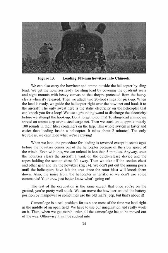
Figure 13. Loading 105-mm howitzer into Chinook.
We can also carry the howitzer and ammo outside the helicopter by sling load. We get the howitzer ready for sling load by covering the quadrant seats and sight mounts with heavy canvas so that they're protected from the heavy clevis when it's released. Then we attach two 20-foot slings for pick-up. When the load is ready, we guide the helicopter right over the howitzer and hook it to the aircraft. The only sweat here is the static electricity on the helicopter that can knock you for a loop! We use a grounding wand to discharge the electricity before we attempt the hook-up. Don't forget to do this! To sling-load ammo, we spread an ammo tarp over a steel cargo net. Then we stack up to approximately 100 rounds in their fiber containers on the tarp. This whole system is faster and easier than loading inside a helicopter. It takes about 2 minutes! The only trouble is, we can't hide what we're carrying!
When we land, the procedure for loading is reversed except it seems ages before the howitzer comes out of the helicopter because of the slow speed of the winch. Even with this, we can unload in less than 5 minutes. Anyway, once the howitzer clears the aircraft, I yank on the quick-release device and the ropes holding the section chest fall away. Then we take off the section chest and other gear and lay the howitzer (fig 14). We don't put out the aiming posts until the helicopters have left the area since the rotor blast will knock them down. Also, the noise from the helicopter is terrific so we don't use voice commands! Your crew just better know what's going on!
The rest of the occupation is the same except that once you're on the ground, you're pretty well stuck. We can move the howitzer around the battery position by manpower or sometimes use the old man's jeep, but that's about it!
Camouflage is a real problem for us since most of the time we land right in the middle of an open field. We have to use our imagination and really work on it. Then, when we get march order, all the camouflage has to be moved out of the way. Otherwise it will be sucked into
34

Figure 14. Laying of the howitzer.
the helicopter rotor blades or one of your men will be knocked down by flying branches.
Well, that's about it from start to finish. When you first start this air assault business, you'll probably miss your section truck. But, after making a few trips by helicopters and working out any bugs, you'll realize that helicopter lifted artillery is a real break in mobility. How else can you move 80 km in 30 minutes? You'll no longer have to stay on the road and get ambushed or wait out of action for a bridge to be prepared. You'll also find the time for occupation and march order is really not much slower than in towed artillery and is more than compensated for by the speed of the helicopter.
I know you'll take to air assault like a duck takes to water. I did! Sincerely, Roland
The SKINNY Battery Captain Ronnie J. Renfro
6th Battalion, 81st Artillery The "skinny" battery is a new concept developed to provide the fast
moving, hard hitting, 11th Air Assault Division infantry units with highly mobile, responsive and accurate ground fire support for short duration operations. Depending on the availability of aircraft, the skinny battery consists of either four or six M102, 105-mm howitzers with six-man gun crews and a fire direction center of three or four men. Only the equipment absolutely necessary for firing is carried. For the firing battery, this means howitzer section equipment and ammunition. The FDC takes only plotting equipment, two firing charts, two AN/PRC-25 radios and two RC-292 antennas. With the small amount of equipment, the airlift requirement for the skinny battery is surprisingly small.
Ideally, three UH-1Ds are required for each howitzer section. One Huey must be equipped with the 48-foot rotor to lift the M102 howitzer while the two ships that lift the crew and ammunition may be equipped
35

with the standard rotor blades. For a four-gun battery, the air-lift requirement is 12 UH-1Ds; for a six-gun battery, 18 UH-1Ds.
It is possible to reduce the number of ammunition carrying UH-1Ds to two by carrying only ammunition sufficient to commence firing and supplying more immediately by a CV-2 using the low level extraction (LOLEX) method The CV-2 can deliver two pallets of 105-mm ammunition (a total of 48 rounds) directly to the battery position in minutes.
It is possible also to resupply the skinny battery by CH-47 which can deliver 128 rounds on pallets direct to each howitzer site. When the Chinook is equipped with roller conveyors, the nose of the ship is raised and the pallets slide out making a quick, effortless delivery. There are many ways to solve the ammunition problem; the one chosen is that which is best suited to the availability of aircraft and the situation.
The M102 howitzer is well suited for this fast moving operation because it weighs only 3,180 pounds, has 6,400-mil on-carriage traverse, and can fire extended range ammunition. The skinny battery is skinny only in the sense of weight; it still delivers a potent punch!
On one occasion, Battery A, 6/81st Artillery received a mission to support a battalion task force on a long range assault more than 65 km behind enemy lines. Only 10 UH-1Ds were available to support the operation. However, three CV-2 (Caribou) aircraft would be provided for LOLEX resupply of ammunition.
It was decided to take four M102 howitzers, making it a real skinny battery and use two of the UH-1Ds to bring in 100 rounds of ammunition on the initial landing. This meant that the battery commander, in his reconnnaissance, would not only have to select a good firing position but one which had sufficient space for LOLEX by CV-2s. This is not prohibitively difficult, but it does complicate the reconnaissance and selection of position.
The battery commander made his reconnaissance and returned to the battery. He had no sooner landed than he was informed by the reconnaissance elements of the cavalry squadron that the position he had just selected was being occupied by enemy forces. He immediately took off in his OH-13 to look for an alternate position area. Time became critical since the battery was to follow him in less than 30 minutes. With the aid of the battalion S2 and the executive officer of the Little John battalion who was in the area, a new position was selected farther away from the objective but still within range and free from the enemy.
Meanwhile, back at the battery, the battery executive prepared to move out. About 7 minutes prior to the arrival of the helicopters, the firing battery started to march order. They had just completed this operation when the four howitzer lift ships came into position, hovered over the howitzers, were hooked up, and took off. Immediately behind the howitzer ships came the ammunition and personnel ships. The ammunition slings were hooked up, the personnel ships loaded with gun crews and FDC men, and the skinny battery was on the way!
Although the personnel ships took off last, they reached the new position area first because of their greater speed. The personnel unloaded,
36

Figure 15. Unhooking and hooking the sling for the M102 is a
matter of split-second timing. guides took their posts, and local security was established.
Air assault time is measured in minutes and seconds, and hard on the heels of the personnel ships came the howitzers followed by the ammunition. The touchdown of each howitzer and ammunition load was gentle, the mark of a good pilot; the release of each sling load (fig 15) a matter of split second timing, and the aircraft were gone.
Laying the battery is a simple matter for the accomplished artilleryman and took less than 6 minutes from touchdown of the first howitzer. Guides were already posted on the flank of the battery to control the LOLEX delivery of the ammunition. With neat precision, the CV-2s came into sight and made their approach. The pilot released the extraction chute, felt the load go and roared off under full power. The skinny battery displaced, was ready to fire, and was supplied with ammunition in less than 1 hour. In fact, with a 35-minute flight, the battery had been out of action for only 55 minutes. In this short span of time, it had moved 65 km over a wide swift river, a swamp, heavily forested hills and enemy strong points. It had brought to the air assault infantryman the assurance of close and continuous fire support for the operation.
There are three disadvantages to the skinny battery concept. They are: too few personnel to provide adequate local security; shortage of
Figure 16. The skinny battery displaces after short term mission
accomplishment, or it is rejoined by elements left in the rear area.
37

personnel and equipment for sustained operations; and lack of ground transportation.
The advantages of quick reaction time, a high degree of mobility, and low aircraft requirements greatly outweigh the disadvantages and make the skinny battery another means which will permit the artillery to continue to fulfill its mission of providing close and continuous fire support to the infantryman, no matter how fast or how far he ranges.
Supply With Diversity Major Buford Brannon
Division Artillery Headquarters Captain Donald R. Davis
5th Battalion, 38th Artillery In a nutshell, an air assault division runs an area type supply system. An
understanding of that system, in general concept, is necessary to the understanding of the logistical operations of the division artillery within the system.
We have called the overall supply system an area type system because the using unit's source of supply depends more upon where the unit is than on where it fits into the organization for combat. In tactical situations, the division support command habitually establishes a division base and up to three brigade bases. Support command personnel operating the brigade bases are formed into forward support elements, generally referred to as FSE1, FSE2, or FSE3 (incidentally, confusing some artillerymen when they first hear that an FSE is responsible for their supply support). A brigade base, or more correctly, the forward support element in the area of a brigade, is the supplier for all units positioned in or operating out of that brigade's area. Units back of the brigade are supplied from the division base. This does not mean that the forward support elements physically handle all supplies going to units for which they have the responsibility. In fact, in actual delivery, the brigade base will be bypassed as often as possible, but it still acts as the retailer, ordering direct delivery to users when possible. Maintenance support, medical support and such field services as shower facilities, salvage collection, and graves registration are also rendered on an area basis.
The flow of supplies (fig 17) starts behind the division. The log command supporting the division ships the supplies as far forward as possible into the division area, delivering to brigade bases or units, using transportation means under log command control. Once supplies have been off-loaded in the division area, any further movement is under division control and is made with division transportation resources or the resources of supporting units. Supplies are moved within the division utilizing aircraft allocated for logistical purposes and by making full use of ground transport means as the situation permits. Unit distribution of supplies is the ideal, but units are required to accept supply point distribution
38

when unit resources are available and adequate for the purpose. Air delivered supplies are usually palletized and sling-loaded by helicopter to shorten delivery time.
This area system described as concept is used by the 11th Air Assault Division with minor deviations from the concept being necessary from time to time. The following paragraphs will describe how this system has been used to solve the division artillery's logistical problems.
CLASS I The play of Class I is complicated to an extent by the injection of large
quantities of A-rations which do not lend themselves to palletizing. For that reason there have been numerous departures from unit distribution as visualized in the concept. C-rations are carried forward on sling-loaded pallets or internally loaded in aircraft and given supply point distribution from the brigade bases whenever possible. When not possible, or in some cases just to explore the possibilities of the situation, unit distribution is made with helicopters. A-rations are issued by supply point distribution only. A-ration meals are prepared generally at battalion level, but it is convenient for individual batteries to equip themselves with a burner unit from a field range and a few pots in order to be able to cook simple meals like breakfast at the battery site. Water is as much a problem as are meals. Water is usually given supply point distribution. One innovation has been tested to an extent within division artillery and seems to offer a solution to the problem of supplying units with needed water. Collapsible five-gallon plastic water jugs (Lug-a-Jugs) are filled at water points, palletized and delivered to unit locations by a sling load. The jugs are reusable and easy to recover. On balance, even though unit distribution of rations and water has not in effect been tested for any extended period of time, the idea has been tested often enough to prove its feasibility, assuming the use of C-rations or some other form of prepackaged ration.
CLASS II AND IV Class II issues involve no special features of interest. Class IV supplies,
mainly lumber and barrier materials, are issued by supply point distribution. Expendables normally considered self-service store items are issued on requisition through supply channels. A good flow of supplies has been established and no problems have developed in that area. The flow of PLL parts has worked so well that most division artillery units have ended testing periods with a better percentage of PLL on hand than that with which they started. All expendables receive supply point distribution.
CLASS III It is with Class III and IIIA that the resupply system receives its acid test,
and it is with Class III and IIIA that special resupply problems relating to division artillery become apparent. To make these special problems clearer, let's take a look at how a forward support element goes about preparing to resupply a particular unit.
The forward support element and the division base must be aware that a given unit will be operating in a given brigade area. Initially,
39

Figure 17. Schematic of supply support.
this appears simple because the organization for combat indicates generally who can be expected to be where, relative to supply bases at the start of an operation. Thus, when a brigade has secured an objective area and requested the forward support element to displace forward to that area, the forward support element displaces expecting to provide service for specific elements of the division, and the support command starts supplies flowing toward the brigade bases to meet that expectation. As changes in organization for combat occur, responsibility for a unit is shifted.
The first problem division artillery encounters is fitting general support artillery into the area supply system. Assigning the mission of general support or general support-reinforcing to an artillery unit may make it possible to designate an initial supporting base, but the very nature of those missions makes it unlikely that geographical relationships will long endure. This problem is met by requesting supply support from forward support elements for specific batteries rather than for the general support units as battalions, thus, dividing the support responsibility as the unit is divided. Even this is not a complete solution because on occasions batteries move on very short notice to an area far removed from their initial location, require support for a few hours or days, and then, as suddenly, shift to a new area. Problems in resupply of Class IIIA underscore this problem. The aerial rocket battalion, or its batteries, can not stay pinpointed to one refueling site and at the same time operate in more than one brigade area. Nor can they accurately forecast in which area they would next need JP4 support in greater quantities than their latest estimates indicated. There is no simple solution. Each threatened stoppage of the flow of fuel is met with a joint support
40
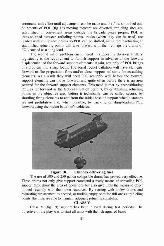
command-unit effort until adjustments can be made and the flow smoothed out. Shipments of POL (fig 18) moving forward are diverted, refueling sites are established in convenient areas outside the brigade bases proper, POL is trans-shipped between refueling points, trucks (when they can be used) are loaded with collapsible drums so POL can be shifted, and aircraft refueling at established refueling points will take forward with them collapsible drums of POL carried as a sling load.
The second major problem encountered in supporting division artillery logistically is the requirement to furnish support in advance of the forward displacement of the forward support elements. Again, resupply of POL brings this problem into sharp focus. The aerial rocket battalion will have elements forward to fire preparation fires and/or close support missions for assaulting elements. As a result they will need POL resupply well before the forward support elements can move forward, and quite often before there is an area secured for the forward support elements. This need is met by prepositioning POL as far forward as the tactical situation permits, by establishing refueling points in the objective area before it technically can be called secure, by shuttling firing elements to and from the initial base of support when distances are not prohibitive and, when possible, by trucking or sling-loading POL forward using the rocket battalion's vehicles.
Figure 18. Chinook delivering fuel.
The use of 500 and 250 gallon collapsible drums has proved very effective. These drums not only give support command a ready means of spreading POL support throughout the area of operations but also give units the means to effect limited resupply with their own resources. By starting with a few drums and requesting replacement as needed, or trading empty ones for full ones at refueling points, the units are able to maintain adequate refueling capability.
CLASS V Class V (fig 19) support has been played during test periods. The
objective of the play was to start all units with their designated basic
41

Figure 19. Pallets of ammunition being loaded in Caribou.
load and to resupply them as it was consumed. To make the play realistic, ammunition boxes were filled with washed gravel so that the boxes approximated the weight of the ammunition represented. The ammunition was palletized into standard mixes of small arm ammunition, or ammunition for primary weapons, and each type pallet given a code number. This procedure permits the unit to request resupply by radio transmission of a code number to the supporting forward support element, cutting down on the length of the transmission and reducing the possibility of error. The standard transportation order is not used (requisitioning by radio is the normal procedure on all classes of supply except Class II and IV). Delivery is accomplished by a variety of methods: sling-load, CV2 to brigade bases then forward by truck, internally loaded helicopters, LOLEX from CV2s, and in the case of the aerial rocket battalion, unit reloading of weapon systems at refueling sites.
Within the battalion, the basic load is taken from the pallets and positioned by the guns. Upon displacement, the basic load is either loaded internally in helicopters or moved in cargo nets as a sling load.
The logistics effort succeeds in supplying division artillery when needed and as needed, despite the tremendous bulk and tonnage involved. The artillery units display versatility and flexibility in being able to absorb the influx of ammunition coming to them by such a diversity of means. Experience gained to date has been basic experience. Accomplishments reach out past the specialized area of air assault and offer artillery units of all types the promise of a new way to receive logistical support in modern warfare.
————— ● ————— GEM FOR FDC PERSONNEL
Fire support coordination within the air assault division poses many new and unique problems. One of these is the rapid distribution of the fire plan which includes coordinated preparatory fires. This problem is caused by the vast distances between fire support agencies, the various
42

types of fire power available, and the short time in which they must react. The normal type "measle sheet" and overlay fire plan is inadequate and too time consuming for use with air assault units.
Figure 1. Message form.
To solve this problem, the artillery liaison officer (LO) at the infantry battalion level devised a coded message format called a "Hopscotch Message." This message provides each fire support agency with the necessary information to enable them to fire preparatory fires and to give required support in the rapid assault of an objective.
A sample use of the message format is as follows:
The infantry battalion commander initiates a rapid reaction attack utilizing one or two companies. H-hour is within 30 to 45 minutes. Tentative landing zones (LZ) and the flight routes are selected. With the LO, the infantry commander plans preparatory fires for the LZ. Knowing the scheme of maneuver and attack plan, the LO fills out the message form (fig 1) as completely as possible and transmits it by radio to the various fire support agencies:
● Line A will include the objective code name and location. ● Line B is the tentative H-hour (troops landing on the objective). ● Line C is the tentative landing zones. ● Line D is the flight route giving the IP, RP and various check points
with their time in minus minutes from H-hour (these will not change even though the H-hour is changed).
● Line E through H will give each agency the information as to what target to hit, when, and with how much. Each line has a number of sublines based on the schedule of fires desired. For example, line E(1) tells the Little John unit to plan to fire one HE round on LZ 1 at H-2 minutes. Line E(2) tells the Little John unit to plan to fire one HE round on LZ 2 at H-2 minutes. As the situation changes and fires are desired only on LZ 2 at H-2, all that is necessary is to call the unit and tell him to "Fire Schedule 2 only."
● Line I is the zip code (borrowed from the U.S. Post Office) which consists of a series of easily identifiable terrain features to be used as reference points by FOs and aircraft. Much the same as concentrations, zip numbers are easier and faster to use.
● Line J is used to show any deviations, irregularities or special instructions. All radio nets have assigned channel designators. The DS artillery battalion F2 net is shown in the example.
—Captain Cecil D. McDaniel, Jr. and Captain Robert D. Offer, Jr.
43

ARTILLERY IN THE DESERT Major Bruce M. Miller
Headquarters, 2d Armored Division Artillery
In addition to a rich mohogany suntan and a conversational familiarity with the flora and fauna of the great American Desert, most "Desert Strikers" brought home a rare and valuable commodity—desert warfare experience. U.S. troops had neither fought nor maneuvered in the desert since 1943. Both the climate and the terrain were unfamiliar and at times downright unfriendly, but both became tolerable with familiarity.
Prior to leaving the relatively mild climate and lush vegetation of Fort Hood, Texas, all officers and men of the 2d Armored Division, also known as “Hell on Wheels,” were indoctrinated in the hazards of the desert. We learned to recognize the various poisonous insects (scorpions, centipedes, and spiders) and reptiles (diamondback and sidewinder rattlesnakes) as well as various kinds of vegetation. We learned of the treacherous Cholla or "jumping cactus." Cholla stems rapidly detach from the main plant at the slightest brush, and the spines are barbed in such a manner as to defy all efforts to remove them; “in fact they seem to work continually deeper as the muscles in which they are imbedded are flexed. We also learned of the friendly "Barrel Cactus," from which a desperate man can obtain water, and the majestic old man of the desert, the Saguaro Cactus.
Acclimatization of the troops to the desert was not so much of a problem as we had expected. The activities of the day were arranged to take maximum advantage of the cool morning and evening hours. Because of the danger of serious sunburn from only short exposure to midday sun, sunbathing was permitted only after 1600 hours daily. Regular use of salt tablets and increased liquid intake soon became routine, motivated perhaps by the sudden collapse of several individuals who ignored these precautions. The very dry air made perspiration almost imperceptible. The fluid loss resulting from even short periods of moderate exercise was serious if it was not replaced. The heat tended to dull appetites, and some of the younger men were likely to forego the balanced meals in the mess in favor of "PX goodies," such as candy, cookies, and soft drinks. A high sugar intake coupled with the desert heat, and even mild physical activity, could make a man violently ill without warning.
Poisonous insects and reptiles were less hazardous than we expected. We quickly formed the habit of never putting on any clothing without first shaking it and inspecting it for uninvited visitors. Snakes were fairly common in the area. Only two cases of snakebites were reported in the 2d Armored Division. Both were the result of carelessness, and neither was fatal.
Quite apart from the health hazards were the problems of terrain. The dominant terrain features were the barren and extremely rugged
44

mountain ranges. These were generally passable only by difficult and restrictive routes. The area between the mountains consisted of semi-crusted sand foothills broken by steep walled arroyos and blown sand dunes. This terrain was not readily trafficable by wheeled vehicles. Occasional dry lake beds also appeared. Some of these lake beds were highly salted and therefore thickly crusted. Others were only thinly crusted and were untrafficable once the crust was broken. The larger arroyos were wooded and provided some degree of cover and concealment. They were generally trafficable, although their steep walls restricted entry and egress. This made them extremely dangerous in the event of a flash flood which could occur with little or no warning.
The heavy wheeled vehicles were generally restricted to improved or semi-improved roads. On the other hand, tracked vehicles, light wheeled vehicles, and super balloon tired vehicles (such as the Honest John launcher) could move freely over most of the terrain. The mountain slopes and certain sand dune areas were impassible to all traffic.
Artillery units found it necessary to organize into combat and trains elements. The full-tracked combat elements traveled cross-country with the maneuver elements. The trains, composed of most of the wheeled vehicles, followed on the road net. Careful planning was necessary to insure frequent rendezvous for resupply of Class I, III, and V. This scheme of organization and operation revealed some rather serious deficiencies in current TOEs.
The medium and heavy howitzers lacked an adequate on-carriage ammunition capacity, and there was no cargo vehicle available which could accompany them in desert terrain. Resupply of both conventional and nuclear ammunition thus became a matter for the most careful planning. Aerial resupply, despite its tremendous expense, may well be the only feasible method of resupply, unless a full-tracked ammunition vehicle is supplied at the battery level.*
The great distances encountered in the desert and the relative unreliability of existing AM and FM communications equipment point to the necessity for a long-range radio mounted in a tracked vehicle. Since all of the AM radios in the division artillery were mounted in 3/4-ton trucks, maintenance of RATT communications between the Division Tactical Operations Center and the nuclear fire units of the 155-mm/8-inch battalions are virtually impossible during a "jump" situation. Tactical necessity dictated that almost every conceivable means of communications be used at one time or another to pass nuclear fire mission traffic.
The recovery of disabled vehicles and their crews was a major problem. The vast distances and the frequency with which breakdowns seemed to occur, in places remote from any road, made it imperative that the unit possess the capability of evacuating disabled vehicles to the nearest road. If vehicles were left behind in remote areas, it was vital that the crews remained with the vehicles and did not attempt to
* The need for a vehicle to accompany our self-propelled howitzers has been recognized. The answer is the XM548 cargo carrier which is in the testing stage. For more information on the XM548 see the December 1964 issue of ARTILLERY TRENDS, page 65.
45

move until help arrived. One disabled vehicle was lost for four days because the crew moved it less than a mile from the place where the recovery crew was told to find it.
By day or night, land navigation presented some unusual problems in the desert. The great distances between identifiable terrain features in the desert made determination of position difficult. Survey control was generally confined to the highways and railroad right-of-ways. Occasional isolated "level stations" could be located in otherwise desolated areas, but horizontal control was uncertain at best. For relatively short range weapons systems, such as cannon, observed firing charts were the only feasible solution for the rapidly moving situation. This should be augmented by a combination of map inspection and local directional traverse.
The Honest John and other tactical rockets of longer range will not find this solution to be acceptable. However, since these systems are essentially roadbound in the desert (except Honest John) and generally possess enough range to overcome any limitations which this might impose, survey is feasible. Furthermore, the exceptionally clear atmospheric conditions virtually assure favorable astronomic observations.
Perhaps the most challenging problems of all those encountered in these stark environs was the problem of camouflage and concealment. Except in the arroyos, the vegetation was very sparse and generally low. Therefore, it offered little or no concealment. Likewise, nets were difficult to garnish in the drab but everchanging hues of the desert. Even worse, nets invariably produced telltale shadows which contrasted markedly with the background of the desert. However, experience showed the nets worked best when draped in an irregular manner allowing them to blend with the shadows of the vegetation. The use of camouflage paints and natural earth mixed with water worked well. After the first few days a uniform coating of fine dust covered both man and material so they blended well with the background. This was moderately effective when coupled with the concealment afforded by the arroyos.
The wide open spaces of the desert made observation relatively simple from the standpoint of object detection. Movement was invariably betrayed by the accompanying dust cloud. The still air, particularly in the early morning and the late evening, tended to make the dust cloud hang stationary. Because of the great distances at which the observation normally took place, the identification of targets and the location of them with an acceptable degree of accuracy was difficult. Aerial observation was particularly effective and allowed identification of targets which otherwise could not be identified. However, this was not without hazard, for he who ventured too close established the target's identity by a distinctly unfriendly attitude.
In the final analysis our problems and solutions were not as different as we had supposed. Most problems of the desert, like those of more familiar environs, demand the accurate analysis of the elements of the problem and application of available resources in accordance with basic principles.
46

Why Single Sideband?? a layman's explanation
Major George F. Beall Communication/Electronics Department
Recently, discussions have been heard concerning the development of a new family of single sideband (SSB) radios by the U.S. Army which will replace our current amplitude modulated (AM) radios. It seems that unless an individual is an electrical engineer, he may not understand single sideband and why these radios will provide improved medium-range communications in the artillery.
Single sideband is not new. It was first employed prior to 1920, and military, commercial, and amateur radios of this type are presently available. The U.S. Army became interested in the tactical use of single sideband as a communication means in the midfifties. This resulted in the development of a completely new family of medium range tactical radios to replace the current AM equipment.
The purpose of this article is to explain, in layman's language, the basic differences between single sideband and amplitude modulation and how these differences can increase communication capabilities.
COMPARISON CHARACTERISTICS AM emission consists of a carrier, an upper sideband, and a lower sideband
(fig 1). With AM, a radio frequency carrier is transmitted anytime the transmiter of the radio set is activated. Approximately two-thirds of the available power output is used in the transmission of this carrier. Intelligence which is transmitted modulates this carrier and uses approximately one-third of the available power output. Both sidebands contain identical intelligence. AM utilizes a bandwidth of approximately 10 kilocycles for each operating channel.
SSB operates on the same principle as AM. However, there are some very important differences (fig 1). With SSB, one of the sidebands is filtered out and is not transmitted. The carrier is suppressed approximately 40 decibels. This means that only one ten-thousandth of the available power output is applied to the transmission of the carrier. All remaining power output then, is used for transmission of intelligence. The resultant power ratio advantage is about six to one over AM, thus permitting greatly increased operating efficiency.
The bandwidth requirement for SSB is normally 3 kilocycles for voice transmission but can be as narrow as 1 kilocycle for continuous-wave (CW) and teletype. Consequently, SSB provides more than three times the number of operating channels when compared to AM. However, because of very stable components in the radio and the ability to have operating channels available at each kilocycle, SSB actually provides up to 10 times the number of operating channels in a given frequency spectrum, compared to current AM equipment. In addition, because of the use of a
47

very narrow bandwidth, less noise is introduced in the receiver; thus, better reception is available with SSB than with AM.
Figure 1. Amplitude modulation (left) and single sideband (right).
The current AN/GRC-19 and AN/GRC-46 AM radios operate in the frequency range of 1.5 to 20 megacycles and provide approximately 1,850 operating channels based on a bandwidth of 10 kilocycles (fig 2). The new SSB radios, operating from 2 to 30 megacycles, provide a large increase in the number of available operating channels. In this frequency range, SSB provides 28,000 channels because operating channels can easily be selected in increments of 1 kilocycle. Our new AN/VRC-12 series FM radios, which require a bandwidth of 50 kilocycles, provide 920 operating channels in the frequency range of 30.00-75.95 megacycles. The SSB radios in the new family provide 50 times the number of operating channels available with current FM radios within a given frequency range. It is interesting to note that if SSB were used in the spectrum currently used by the new FM equipment, that is, 30.00 to 75.95 megacycles, 46,000 operating channels would be available.
Many times a question is raised about the power outputs of AM and SSB radios and how a comparison can be made. The rated power output of SSB radios is referred to as peak envelope power (PEP). There simply is no easy way in which peak envelope power may be correlated to power output of an AM radio because transmitter power is applied only when intelligence is transmitted using SSB.
In addition to the SSB advantages of more operating channels available within a given frequency spectrum; greater operating efficiency using less power output; and better reception because of less noise in the receiver due to the employment of a very narrow bandwidth, there are two rather technical reasons why SSB improves communication. These are reduction of intermodulation interference and the absence of the "threshold effect" characteristics of FM.
48

Figure 2. Utilization of frequency spectrum for FM, AM, and SSB.
INTERMODULATION Intermodulation may be defined as interference caused by other stations
operating on different frequencies. This interference is caused by the formation of additional frequencies through harmonics. To explain this in more detail, if two radio sets are operating on frequencies 3 and 5, respectively, interference will occur on any radio operating on frequencies 11 or 13. This intermodulation interference is produced by the first harmonic of one frequency added to the other frequency to produce a third. In other words, the first harmonic of 3 is 6. When 6 is added to 5, the other frequency, intermodulation interference will occur on frequency 11. Likewise, the first harmonic of 5 is 10 and, when added to 3, produces frequency 13 on which intermodulation interference will occur
This intermodulation interference occurs only when sharp, strong signals, such as carrier frequencies, are present. SSB is unique among other types of modulation because the radiated power output in SSB equipment is proportional to the intelligence transmitted at any given moment. With SSB radios, practically no power is radiated when intelligence is not being transmitted. When intelligence is transmitted, the power radiated is proportional to the intensity of the transmitted intelligence.
The human voice, CW, and teletype are characterized by short peaks of high power and relatively low average power. If SSB modulation is used, the radiated power will follow this same distribution, and the transmission will be characterized by relatively short, infrequent bursts of radiated power. This characteristic of SSB greatly reduces the level of intermodulation interference, which is one of the major problems in crowding systems together and obtaining better frequency spectrum utilization.
How does SSB overcome or help reduce this problem? As previously indicated, intermodulation interference occurs only when sharp, strong signals are transmitted. If all the transmitters causing intermodulation are SSB, there is a very small probability that a peak power of one transmitter
49

will coincide with a peak power of another transmitter. It has been estimated that in SSB systems, intermodulation may be reduced by a factor of one to ten. This great reduction in intermodulation may prove to be one of the most important advantages of SSB and will permit a closer geographical spacing between systems and much better spectrum utilization.
LACK OF THRESHOLD RECEPTION The other technical reason why SSB offers improved communication
capabilities is because of a lack of "threshold reception" (fig 3) which is found with FM. The attenuation, or reduction in strength of the received signal (shown on the left edge of figure 3 as the relative signal-to-noise ratio) between transmitter and receiver may be caused by range, noise, or any other effect which reduces the signal-to-noise ratio (S/N) but which has equal effect on both AM and FM. In this case, we will use increments of range, measured from the transmitter near the right edge of figure 3. The relative signal-to-noise ratio is indicated on the left edge of figure 3. Obviously the received signal is of better quality when the S/N ratio is high.
One distinct disadvantage of FM—the inherent loss of range because of the threshold effect—presents a lesser problem with SSB. As illustrated, both AM and SSB are linear in attenuation as the distance from the transmitter is increased. Note that the FM signal, however, drops sharply in signal-to-noise ratio, at about 1,000 to 1, and soon disappears. The very high S/N ratio required with FM produces the high fidelity which is associated with broadcast FM. For example, consider the high quality of reception on the commercial broadcast FM band. In FM, the carrier power has to be approximately 5 to 10 times above the noise level for any intelligible reception of voice. Therefore, the FM systems have a rather abrupt communication range limit beyond which no reception is possible. This represents the threshold effect characteristic of FM. Both AM and SSB can be received far beyond this point and even beyond the point where detected speech is equal to noise.
To illustrate what this means in effective range, figure 4 depicts the result of a test conducted using the same frequency, terrain, and atmospheric conditions. An FM transmitter of 100 watts and a SSB transmitter with 66 watts peak envelope power were used in this test. In region A, both received signals were essentially the same, since they were close to the transmitting stations.
In region B, FM outperformed SSB because of its high signal-to-noise ratio, or high fidelity. You will recall from figure 3 that this is still on the linear portion of performance.
Figure 3. Theshold effect on SSB, FM, and
50

In region C, as FM approaches the listening threshold, both signals were again equal. However, the FM reception was completely lost near the far side of this region because of the threshold effect. The SSB signal was received beyond this point, and although the signal-to-noise ratio decreased, it was understandable throughout most of region D. In this example, an increase in range of about 50 per cent was obtained using a SSB radio with less primary power.
This example is, of course, relative and applies to a given test on a given frequency over certain terrain. However, these relative values will hold true under any conditions.
The advances in our weapon systems and concepts of employment have required the change from amplitude modulation to single sideband to insure increased range and reliability of communications. Single sideband has been used with great success in other services, and tests conducted by the U.S. Army indicate that single sideband radios will prove to be a very reliable medium-range communication system for use in the artillery.
Figure 4. FM and SSB range and S/N ratio performance.
————— ● —————
COMMUNICATIONS CLASS PACKETS The U.S. Army Artillery and Missile School offers 22 class packets
concerned with communication equipment and field artillery communications systems. The classes, which are listed in the "Catalog of Instructional Material," consist of an instructor's manuscript, transparencies and student material. To obtain more detailed information about these or other classes, write to Commandant, U.S. Army Artillery and Missile School, ATTN: AKPSINI/RC, Fort Sill, Oklahoma 73504.
51
NO COMPROMISE with adverse weather and terrain
Major William W. Galloway, Jr. U.S. Army Advisor Group
North Carolina National Guard Frequently, the artilleryman is beset by problems brought about by the
unpredictable affects of weather and terrain. This is particularly true in the area of "occupation of position" where speed and accuracy are of major importance. Over a period of time and through experience gained by trial and error, each artilleryman finds ways to cope with many of these problems.
The theme of this article is necessarily intended to depict the difficulties encountered under adverse weather and terrain conditions: occupation of position in unsuitable terrain, as on lateral slopes and muddy, sandy, or frozen ground; occupation of position in disagreeable weather, as rain and freezing conditions; and occupation under the cover of darkness. It is stipulated, however, that all activities may be deliberate, with a normal amount of time available for reconnaissance, selection, and preparation of position. Many of the measures herein are applicable to all artillery, and some will prove valuable for occupations whether rapid or deliberate and regardless of weather or terrain conditions. While many of the measures described here will apply to field artillery in general, it is pointed out that certain items, specific in nature, are directed toward the 155-mm towed howitzer field artillery battery.
It is submitted that all active measures noted are not prerequisites for the successful occupation of any one difficult position. However, all of these measures may be of sufficient interest to be incorporated into unit training. Then should the need arise, they may be applied, collectively or individually, as the situation warrants.
The primary mission of the artillery unit is the timely, accurate, and continuous delivery of artillery fire support. The degree of success in this mission is frequently the result of prior planning and organization by the unit commander. The purpose of reconnaissance, selection and preparation of a position is to facilitate rapid and orderly movement of the artillery unit into the position. What could be more logical than to have at your disposal a preconceived plan to cope with any reasonable adverse weather and terrain conditions?
Initially, of course, a commander must make every effort to select favorable terrain for an artillery position. Unfortunately, it is not always possible to select desired terrain under suitable weather conditions.
Where hilly or broken terrain is concerned, perhaps the most difficult terrain for occupation by a towed 155-mm howitzer battery is a lateral slope; this is particularly true in muddy or sandy soil. Problems are magnified when the occupation must be made under the cover of darkness.
52
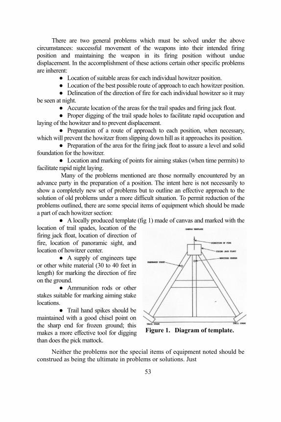
There are two general problems which must be solved under the above circumstances: successful movement of the weapons into their intended firing position and maintaining the weapon in its firing position without undue displacement. In the accomplishment of these actions certain other specific problems are inherent:
● Location of suitable areas for each individual howitzer position. ● Location of the best possible route of approach to each howitzer position. ● Delineation of the direction of fire for each individual howitzer so it may
be seen at night. ● Accurate location of the areas for the trail spades and firing jack float. ● Proper digging of the trail spade holes to facilitate rapid occupation and
laying of the howitzer and to prevent displacement. ● Preparation of a route of approach to each position, when necessary,
which will prevent the howitzer from slipping down hill as it approaches its position. ● Preparation of the area for the firing jack float to assure a level and solid
foundation for the howitzer. ● Location and marking of points for aiming stakes (when time permits) to
facilitate rapid night laying. Many of the problems mentioned are those normally encountered by an
advance party in the preparation of a position. The intent here is not necessarily to show a completely new set of problems but to outline an effective approach to the solution of old problems under a more difficult situation. To permit reduction of the problems outlined, there are some special items of equipment which should be made a part of each howitzer section:
● A locally produced template (fig 1) made of canvas and marked with the location of trail spades, location of the firing jack float, location of direction of fire, location of panoramic sight, and location of howitzer center.
● A supply of engineers tape or other white material (30 to 40 feet in length) for marking the direction of fire on the ground.
● Ammunition rods or other stakes suitable for marking aiming stake locations.
● Trail hand spikes should be maintained with a good chisel point on the sharp end for frozen ground; this makes a more effective tool for digging than does the pick mattock.
Figure 1. Diagram of template.
Neither the problems nor the special items of equipment noted should be construed as being the ultimate in problems or solutions. Just
53

as each commander may be faced with a variation of problems, each commander, through experience and imagination, should find additional and perhaps better solutions. As a minimum, the unit commander should be aware of these items prior to the reconnaissance and selection of position.
In an earlier paragraph it was stated that a commander must make every effort consistent with the tactical situation to select a firing position favorable to his type unit. When the commander finds it necessary to fire from a lateral slope position, he must be especially selective as to the exact location of the weapons. On unfavorable terrain, the location of the individual howitzer is perhaps the most critical task of all. Where there is conflict, the formation of the firing battery should certainly be secondary to the good sound location of each individual howitzer. Success of the subsequent occupation of a position will be greatly enhanced if a few basic principles are followed during the reconnaissance and selection of a position:
● Select with care each individual howitzer position. Although the battery position may be on a slope, careful selection normally will result in sufficient small, relatively flat portions of terrain to accommodate the six howitzers with a minimum of digging and a maximum of stability for the weapons. While formation of the howitzers may be secondary, attention must be given to the proper width and depth of the battery.
● Be sure that a reasonably good route of approach is available to each howitzer position.
● Determine as accurately as possible a direction of fire. ● Alert representatives of each howitzer section to special measures
necessary to assure successful occupation of their howitzer positions. A different situation may exist for each howitzer.
● See to it that the future utilization of the special items of equipment mentioned is assured.
● Advise the chiefs of sections that, should they for any reason fail to occupy rapidly the prepared position when the howitzer arrives at night, they should have their howitzer emplaced as near the original position as possible, but they should not waste critical time in a hopeless effort to occupy a position.
The key to rapid and efficient occupation of a firing position is found in the preparation of the position. This is especially true when operating under poor terrain and weather conditions. Practically all problems resulting from muddy or sandy lateral slopes can be overcome if the following active measures are taken during the preparation of a position:
● The center of each howitzer will be marked by a stake on the ground. ● The direction of fire will be accurately determined and marked on
the ground for each howitzer position. ● The canvas template, which should be marked as shown in figure 1,
will be placed on the ground so that the marking for the howitzer
54

center and the direction of fire on the template coincide with these same markings on the ground. Once this is accomplished, the ground will be marked at the location for the trail spade holes, the jack float area and the panoramic sight. By having the template alined with the direction of fire, the howitzer, when placed in the prepared position, may be layed with no shifting of trails and with very little traverse.
The stake marking the panoramic sight should be left in the ground to be later occupied with an aiming circle to "stake out" the location of the aiming stakes.
Once the ground location of the howitzer is marked, good sound thought must be given to the leveling of the ground for the firing jack float and to the digging of the trail spade holes. There are two types of terrain which will have a definite influence on the digging and preparation of the position—sloping terrain with solid foundation and sloping terrain with muddy or sandy foundations:
● Sloping terrain with solid foundation. On this type soil there should be little danger of the howitzer sliding downhill once it has been emplaced in a level attitude. Care must be given to the digging of the trail spade holes (fig 2). The downhill spade hole should be no deeper than is necessary for achievement of 1,160 mils elevation, and if the ground is reasonably solid and the elevation can be achieved otherwise, the spade hole should not be more than one-half to three-quarters the height of the spade in depth. Under equal terrain and weather conditions, the depth of the uphill trail spade hole should be that which will assure level attitude of the weapon, assuming of course that the proper elevation may be reached. Perhaps the most critical point here is the width and breadth of the spade holes; they should normally not exceed the size required to properly house the trail spade. The only time, on this type of terrain, that the trail spade holes should be dug large enough to allow shifting of trails is when the commander is absolutely certain that available on-carriage traverse is insufficient to cover the assigned sector of fire. Excessively large trail spade holes in this type terrain only invite undesired displacement, especially in the event of rainfall. It should be noted here that the spade initially rests on the top rear of the spade hole. When the howitzer fires, the dirt under the spade will crumble and be cupped and tightly packed to the rear of the spade. The spade was designed with this purpose in mind, and only with this type spade hole design will the original intent of design be fulfilled.
● Sloping terrain with muddy or sandy foundation. Under these conditions, thought must be given to the possibility of the howitzer's sinking, tilting or slipping downhill once firing has begun. This may be prevented not only by digging a hole 10 to 12 inches deep where the jack float will sit but also by building a foundation of rock, gravel or wood to within one and one-half inches of the level of the ground. The width and breadth of the hole and the foundation should be 8 to 10 inches larger than the jack float. Another possibility for prevention of sinking of the jack float is use of a "Spreader." This is a wooden platform,
55

Figure 2. Dimensions of trail spade holes.
three to four inches thick, with the width and breadth 10 to 12 inches greater than the jack float. This may be "dug in" at the ground location of the jack float and will afford an excellent foundation.
● Special attention must be given to the leveling of the jack float area, whether it be earth or constructed foundation. If there is any possibility of tilt, which would result in cant of the weapon, it must be dug into the uphill slope.
There may be a necessity for trail logs but unless the soil is muddy or sandy to the extent that it contains no resistance, trail logs may actually be detrimental (fig 3). In the event trail logs must be used, they should be a minimum of 48 inches in length and large enough in diameter (8 to 10 inches) to allow them to take purchase in the ground. It will normally be necessary to insure the firmness of the trail logs by driving stakes immediately to their rear. Metal stakes should be used where possible. The use of trail logs should be discouraged unless they are absolutely necessary. Figure 3 depicts a trail log being used on relatively firm ground. As the howitzer is fired, the trail log actually becomes a wedge and instead of holding the weapon in place, cuts its way into the ground allowing displacement and negating the purpose of the trail spade.
In many cases it is necessary to prepare an approach to some or all of the howitzer positions. The final 12 to 15 feet of this approach should be made along the direction of fire, from the front of the gun position. This will allow the howitzer to be stopped directly over its stake and pointed in the direction of fire. On an excessively steep or slick slope the approach may be made from a slighly uphill angle. This
56

Figure 3. Use of trail logs.
will provide easier and more controlled movement into the position as opposed to pulling uphill or directly along the slope. When condition of the terrain is such that danger of slipping cannot be averted, a low abutment (4 to 6-inch log staked down) should be erected along the final 12 to 15 feet of the path to be followed by the downhill wheel of the howitzer (fig 4). The wheel of the howitzer will ride against the uphill side of this log and will not slip downhill.
Many active measures have been pointed out in preceding paragraphs; it is the exception rather than the rule, however, when all of these measures need be applied to any one situation. Each individual situation should be carefully evaluated by the unit commander with thought initially directed toward those actions necessary for a successful occupation. Then, as time permits, other measures aiding speed and accuracy may be accomplished.
Figure 4. Diagram depicting howitzer position.
Once those necessary items outlined in the preparation phase have been accomplished, the occupation of this type position is much the same as occupation of any artillery position. There are, of course, certain critical areas that require special attention:
● As the weapons leave the battery release point, they should be led directly to the howitzer positions, without stopping. Any time the prime mover stops in slick or muddy terrain, there is danger of "bogging down."
● Guides should be especially careful to remain on the preplanned route of approach to each position.
● It is paramount that the weapons be led directly over their stake on the first approach to the gun position. In the event the weapon does miss its intended position on the first try, it should be towed
57

around the uphill side of the position and another attempt made on the original approach route.
● As soon as the howitzer is over its stake, its brakes must be locked; the brakes must then remain locked until the trail spades are in their holes and the firing jack is firmly on the ground. This will prevent shifting of the weapon during emplacement.
● If, after a reasonable attempt at emplacement, the howitzer cannot be placed over its stake, an alternate position must be occupied by this howitzer. Nothing is to be gained by wasting critical time in a futile attempt at occupation of a position that by this time probably has been destroyed by the prime mover and the howitzer.
When occupation of the position is complete, the normal battery SOP is placed into effect, and the mission will continue as in a normal situation.
In this type position, as in any artillery position, certain improvements are mandatory, as time permits. Here, the difference in the amount of improvement necessary may be determined by the degree of adequacy and stability of the preparation of the initial position. If the ground is muddy or sandy, periodic checks must be made to determine if the weapon is maintaining its level attitude and that there is no evidence of slipping downhill.
If time during the preparation of the position does not permit digging of recoil pits, this must be accomplished after occupation. Of course, there are many other activities inherent to the improvement of an artillery position. These, however, by virtue of their normality, may be found in appropriate field manuals.
To be assured of the successful accomplishment of the artillery mission, the commander must be prepared to cope with any problems resulting from weather or terrain. He must know first, what problems may be encountered, and second, the appropriate actions to be taken.
The comments mentioned in the first part of this article may be reconciled by careful attention to the following recommendations:
● Develop through training, experience and imagination, a sound but simple plan to cope with any problems presented by unfavorable weather and terrain conditions.
● When on reconnaissance, be very selective of the firing battery position and the individual howitzer positions.
● Have available for use any special items of equipment which may aid in rapid and efficient preparation and occupation of a position.
● Direct, and assure by follow-up checks, the adequate preparation of the firing position. Be especially attentive to the preparation of the approach route to each position and to the accurate layout and digging of trail spade holes and the jack float area.
Whether or not a commander elects to use the measures set forth in this article is not paramount. What is important is that each unit be equipped to meet with confidence, and subsequently overcome, the problems outlined herein, for the accomplishment of the field artillery mission must not be compromised by weather and terrain.
58

PERFORMANCE ═ STANDARDS Management Control With Equipment Log Book
Major John F. Geraci Artillery Transport Department
"What is a "management control" and why is it necessary? Sound management is simply one of the many techniques of effective leadership. The functions of management normally are planning, organizing, assembling, directing, and controlling. Control may be obtained by making a formal analysis of the facts, measuring results, and accomplishing evaluation. An inspection is very much a command control. In an inspection, the inspecting commander knows his desired standards; he examines whatever or whomever he is inspecting and weighs what he sees against what he hopes to see (the standards). This control enables him to take action. If what is revealed by his inspection fails to measure up to his standards, he directs that corrective action be taken. If the results of his inspection meet, or exceed his standards, he can devote his time and energies elsewhere. A good inspector is alert to indications of possible problem areas, and before they become serious he will direct action to eliminate them.
A control, then, is any device which enables a manager to conveniently, easily, and effectively compare performance to standards. Certainly there is no substitute for personal command inspections, but they have drawbacks in that they are time-consuming and seldom permit inspectors to go into great detail. The complexity of the modern Army has created a need for many additional controls—simple devices which can enable a commander to keep his eye on all facets of his command and to do so on a day-by-day basis without spending all his time doing it. One such control is the equipment log book assembly.
Here at the USAAMS, perhaps the most frequent question asked of the instructors who teach The Army Equipment Record Procedures (TAERP) is: "This system seems fine for very high-level commanders, but what can it do for me?" This is a good question, and the answer is: "Plenty—if you know how to use the system."
TM 38-750 gives complete details on TAERP. This article is not an attempt to explain all the details on the use of the system; it is, however, an explanation of the purpose of the system, and you can take it from there.
The log book assembly (complete with inserts) is a control because it efficiently, neatly, logically, and concisely displays significant information concerning maintenance. This orderly portrayal enables the commander or supervisor to "see" performance and to evaluate that performance based on established standards. This is control. For example, one maintenance standard is that all modification work orders will be applied within a specified period of time. The equation or control therefore
59

should be "modifications required=modifications accomplished." If it is properly maintained, the DA Form 2408-5, Equipment Modifications Record, for each piece of equipment on which it is kept will indicate at a glance whether this equation is true for that particular equipment.
Another of the many standards to be met is the accomplishment of all required lubrication services in accordance with the current lubrication order. DA Form 2408-2, Equipment Lubrication Record, serves as one side of the control equation. Each log book insert, in turn, serves as one side of some control equation.
Look at the system in this light. Suppose there were no TAERP or any other record-keeping system to be followed by your unit. "Hallalujah" you say—but wait a minute. To command effectively, you absolutely must have certain information, and a great deal of the information required must be in writing because you (and your successors) will need it for a long time to come. Without TAERP, it would soon become apparent that a voluminous collection of information would be needed to effectively manage maintenance and insure materiel readiness. You need such information to enable you to give intelligent direction to effort and to forestall problems and mistakes. Now, assume that you know all there is to know about a unit's maintenance program and state of materiel readiness. If you were to list all of the information required to make that maintenance program an outstanding one, you would undoubtedly arrive at a requirement for about 90 per cent of the data currently maintained under the Army Equipment Record Procedures. Some of the TAERP data is required primarily for the edification of higher headquarters.
Since this wealth of TAERP control data is available, how do we use it to manage the maintenance program? There are numerous phases or areas of maintenance over which the commander must exercise control. A few of the most important areas are listed here and with them are the forms that can be used as control devices if they are properly completed and maintained:
● Adequacy of operation and crew maintenance training—DA Forms 2404, 2406, and 2408-1 (daily and monthly).
● Adequacy of unit mechanics training and performances—DA Forms 2404, 2408-2, 2408-3, and 2408-14.
● Adequacy of supply—DA Forms 2406, 2408-3, 2408-5, and 2408-14.
● Adequacy of publications—DA Forms 2404, 2408-2, 2408-5, and 2408-14.
● Adequacy of support maintenance— DA Forms 2408-6, 2408-10 and 2408-14.
● Adequacy of supervision—DA Forms 2404, 2408-2, 2408-3, 2408-5, and 2408-14 and DD Form 314.
● Adequacy of planning—DA Forms 2408-5, and 2408-14, and DD Form 314.
● Adequacy of internal coordination—DA Forms 2404, 2408-2, 2408-5, and 2408-14, and DD Form 314.
60

● Parts utilization—DA Forms 2404, 2408-2, 2408-3, 2408-5, and 2408-14.
● POL consumption—DA Form 2408-1 (daily and monthly) and DA Form 2408-2.
By judicious (but brief) examination of TAERP then, the commander can put theory into practice. Ideally the equation should be "performance = standards." Yet, we are too well aware that the truth is most often "performance = some of the standards" or "standards = performance + improvement and corrective action." By proper use of The Army Equipment Record Procedures, the commander can measure precisely his unit's performance and can determine clearly those areas in which improvement and corrective action are needed, pinpointing them to specific functions and persons. What more could a manager want in a control system?
—————●————— XM656 CARGO TRUCK
The U.S. Army Artillery Board has recently completed service tests on the XM656 5-ton cargo truck (fig 1). Twenty-three feet long and weighing 7 1/2-tons, it is capable of towing a 6 1/2-ton load in addition to its 5-ton rated carrying capacity.
Extensive use of aluminum in the cargo body and crew compartment has resulted in a relatively light vehicle with a floating capability and a cruising range of 300 to 400 miles.
At present, the XM656 is undergoing further tests at General Equipment Test Agency, Fort Lee, Virginia, after which the vehicle will be shipped to Panama for tropical environment studies.
The vehicle is expected to be ready for operation by early 1967.
Figure 1. XM656, 5-ton cargo truck.
61

ALPHABETICAL INDEX ARTILLERY TRENDS 1964
(February, June, October, December)
Section I—Articles Article Issue Page
A Collection of Gems ................................................................. June 34 Air-propelled Artillery—A New Challenge ......................... February 37 A Method—Observed Fire Chart Modification ................... February 48 A Picture of Sergeant ......................................................... December 19 Artillery Fire Planning—The Responsibility is Yours ......... February 31 Artillery Fire Planning—The Responsibility is Yours ................ June 16 Artillery of the Federal Germany Army............................... December 38 Artillery Tool House ..............................................................October 41 Artillery Training—Counterguerrilla Warfare ...................... February 11 Capabilities Plus—The M109 ..................................................... June 8 Difficulty in Projection ...................................................... December 11 Division Artillery Airborne TOE's .............................................. June 32 Engineer/Artillery—An Unbeatable Team .................................. June 23 FADAC and Free Rockets .......................................................... June 12 FDC Van Features—Design with Efficiency .........................October 2 Fire Support Element Operations Aids .............................. December 51 Flex-Wing—Pinpoint Glider System ................................. December 59 FM Radios—Speak and Be Heard ....................................... February 25 Go by Army Air ................................................................. December 45 Instructional Material for Artillerymen ................................ February 2 Latest Status Charts—Graphical FDC Equipment ............... February 8 Letter to Artillerymen—175-mm
Gun Firing Experiences ............................................... December 7 Low-Cost Training Aid—Observer Pegboard Trainer ................ June 35 MOS Proficiency With Extension Courses ........................ December 2 New Cannon Potential ...........................................................October 43 Pershing—New Artillery Sunday Punch .............................. February 41 Quarterbacking Tomorrow's Artillery ................................ December 31 The Payoff is Accuracy ..........................................................October 47 The Supported Force—Small Arms Developments ............. February 50 Under Development—Lance ............................................... February 3 Utility Tactical Transport—the Armed UH-1B ........................... June 3 Will Adjust to the First Round Hit—The Future
Story of Target Acquisition ..............................................October 5
62

Section II—Subjects and Newsnotes Subjects and Newsnotes Issue Page
ABLE Orientor ........................................................................October 26 Administrative Support ........................................................ February 23 Aerial Observers .................................................................. February 20 Airborne Division Artillery TOEs ............................................... June 32 Air-Propelled Artillery ......................................................... February 37 Alfa Formation for Armed Helicopters ....................................... June 6 Altitude Method .....................................................................October 18 AN/DPN-62V ........................................................................October 24 AN/GRC-5 ........................................................................... February 18 AN/MPQ-4A ..........................................................................October 11 AN/MPQ-10A ........................................................................October 28 AN/MPQ-29 ..........................................................................October 24 AN/MPQ-32 ..........................................................................October 29 AN/MQM-57A Drone System ...............................................October 22 AN/PRC-5 ........................................................................... February 28 AN/PRC-9 ........................................................................... February 18 AN/PRC-25 ...........................................................................October 52 Antenna Preventive Maintenance ..........................................October 55 AN/TGC-14 ................................................................................ June 14 AN/TPS-25A .........................................................................October 30 AN/TRC-80 ......................................................................... February 44 AN/VRC-12 ...........................................................................October 52 AN/VRC-12 series ............................................................... February 29 AN/VRC-34 ......................................................................... February 18 AN/VRC-46 ......................................................................... February 25 AN/VRC-46 ...........................................................................October 52 AN/VRC-47 ......................................................................... February 26 AN/VRC-49 ......................................................................... February 26 October 52 APO Numbers Change ...................................................... December 10 AR 711-17 Supply Procedures ...............................................October 53 Artillery Fire Planning ......................................................... February 31 June 16 Artillery Radio Maintenance Course Revision .................... February 65 Artillery Target Indicator ..................................................... February 19 ARTILLERY TRENDS ....................................................... February 2 June 2 Astronomic Azimuth ..............................................................October 21 Astronomic Azimuth Determinations ....................................October 16 AT-791 ...................................................................................October 52 AT-1537 .................................................................................October 52 Battalion FDC Vans ...............................................................October 2 Book Department ................................................................. February 2 June 2
63

Subjects and Newsnotes Issue Page Camouflage ................................................................................. June 27 CH-34/4.5-inch Rocket Weapon System ............................. February 38 CH-47 Helicopters .................................................................October 43 Class Packets ....................................................................... February 2 June 2 Combined Arms Training .................................................... February 23 Communications Courses ........................................................... June 50 Computer Orientation Trainer .............................................. February 68 Computer Terms Glossary ................................................... February 24 CONEX Container .................................................................October 41 Counterguerrilla Warfare ..................................................... February 11 Counterinsurgency Operations .......................................... December 11 Distance Measuring Equipment .............................................October 32 Duplex Rifle Cartridge ..........................................................October 40 Effective Target Acquisition Coverage ..................................October 28 Engineers .................................................................................... June 23 FADAC ..................................................................................October 36 FADAC Accuracy ..................................................................October 47 FADAC Computer ...................................................................... June 12 FADAC Interference ................................................................... June 49 FADAC Programs for M109 ....................................................... June 60 Field Artillery Extension Courses ........................................ February 2 June 2 Field Checks for FM Radios ................................................ February 29 Fire Direction ....................................................................... February 20 Fire Planning ........................................................................ February 15 Fire Support Coordination Class ........................................ December 58 Fire Support Element ......................................................... December 41 Firing Battery ....................................................................... February 13 Firing Chart Altitudes ................................................................. June 15 Firing Table Distribution ..................................................... February 62 Flex-Wing .......................................................................... December 59 FM 6-2 ...................................................................................October 35 FM 6-40 ............................................................................... February 7 June 15 FM 31-15 ........................................................................... December 12 FM 100-5 ........................................................................... December 16 FM Radios ........................................................................... February 25 June 49 Fort Gibson Dam ........................................................................ June 25 Forward Observer's Packet ................................................ December 63 Geneology of Target Accuisition ...........................................October 9 German Army Artillery ...................................................... December 38 Graphical FDC Equipment .................................................. February 8 Ground Forward Observers ................................................. February 17 GRR 5 ....................................................................................October 2 Gun, 175-mm FDC Status Charts ........................................ February 8
64

Subjects and Newsnotes Issue Page Honest John Rocket .................................................................... June 12 Hour Angle Method ...............................................................October 20 Helicopter Operations............................................................ February 22 December 45 Howitzer, 105-mm FDC Status Charts ................................ February 8 Howitzer, 155-mm, Developments ...................................... February 57 Howitzer, 155-mm FDC Status Charts ................................ February 8 Howitzer, 8-inch FDC Status Charts .................................... February 8 Instant Survey ........................................................................October 11 Instructional Material ........................................................... February 2 Instructional Material for Artillerymen ....................................... June 2 Instructional Material—175-mm Gun ................................ December 10 Instructional Material for Sergeant .................................... December 30 Intelligence .......................................................................... February 21 Lance Missile System .......................................................... February 3 LASER Rangefinder ..............................................................October 39 Little John Rocket ....................................................................... June 12 Logistical Support ................................................................ February 23 M102, 105-mm Howitzer ......................................................October 43 M107, 175-mm Gun .......................................................... December 7 M109, 155-mm Howitzer ........................................................... June 8 M109, 2½-ton Truck (shop van) ............................................October 2 M557 Command Post Carrier ............................................ December 65 M3, 2.75 Aerial Rocket System .................................................. June 4 M4T6 Bridge .............................................................................. June 27 M114A1, 155-mm Howitzer ....................................................... June 9 M44A1, 155-mm Howitzer ......................................................... June 9 M113A1 Tracked Vehicle .................................................... February 5 M14 Rifle ............................................................................. February 50 M16 (AR 15) Rifle .............................................................. February 51 M2 Compass ........................................................................ February 19 M79 Grenade Launcher ....................................................... February 51 Matrix for Free Rockets .............................................................. June 13 Maximum Altitude Angle ......................................................October 17 Meteorological Sounding Balloons .......................................October 25 Meteorology ......................................................................... February 21 Mine Detectors ........................................................................... June 29 Miniature Radio Set ............................................................. February 52 Minimum Altitude Angle .......................................................October 17 Missile Installations .................................................................... June 25 Mobile Assault Ferry .................................................................. June 26 MOS Evaluation ................................................................ December 2 MOS Proficiency ...................................................................October 40 MOS Subcourses ............................................................... December 3 New Night Vision .............................................................. December 50 Nuclear Power Plants .................................................................. June 25 Observed Fire Chart Modification ....................................... February 48
65

Subjects and Newsnotes Issue Page
Operations Aid for FSE ..................................................... December 51 Orienting Angle Change ............................................................. June 50 OT Factors .................................................................................. June 37 Pegboard Trainer ......................................................................... June 35 Pershing Missile System ...................................................... February 41 POIs ............................................................................................ June 2 Prefire Tests for Lance........................................................... February 5 Principles of War ............................................................... December 13 Program of Instruction ......................................................... February 2 Protective Measures for AN/VRC-12 Radios ...................... February 62 RADA Communications System ...........................................October 46 Radio-Telephone Training ............................................................ June 54 RC-292 ..................................................................................October 52 February 18 Readers' Comments ............................................................. February 61 June 54 October 56 Receiver R-442 .................................................................... February 25 Revised Maintenance Training ................................................... June 52 Rocket Artillery .....................................................................October 51 RT-524 ................................................................................. February 59 S-64 Flying Crance .............................................................. February 59 School Course Changes ..................................................... December 64 TPI Booklet ............................................................................October 4 UH-1B Helicopter ....................................................................... June 3 Universal Engineer Tractor ......................................................... June 26 USAAMS Crest .......................................................................... June 38 USAAMS History ....................................................................... June 50 October 52 USAAMS Safety Criteria Study ........................................ December 44 USACDC Artillery Agency ............................................... December 31 VATLS ...................................................................................October 14 VRC-9 ....................................................................................October 2 Weapon Employment ........................................................... February 12 XM474 Tracked Carrier ....................................................... February 43 XM548 Cargo Carrier ........................................................ December 65 XM6 (Emerson) Machinegun Kit ............................................... June 3 XV-4A Hummingbird .......................................................... February 58 XV-5A Plane ........................................................................ February 58
Section III—Gems
Gem Issue Page Ammunition Drum ..................................................................... June 64 Arrow-Shaped Marker for Howitzers ......................................... June 43
66

Gem Issue Page Colored Board Markers for Howitzers ....................................... June 43 Covers for Radio Mounts ............................................................ June 44 Deflection-Correction Scale ..................................................October 61 Emplacement Rod for Aiming Stake .......................................... June 41 Equipment Serviceability Check ................................................ June 40 FDC Helps .................................................................................. June 48 Flash Observer Training .................................................... December 18 GFT Elevation Gageline Construction ........................................ June 53 Howitzer Marker Patterns ........................................................... June 40 Howitzer Position Orientation Board .......................................... June 42 Individual Weapons Rack ........................................................... June 42 Lance Pole for Overhead Wire .................................................... June 45 Lighting Device .......................................................................... June 40 Man-Handling of 8-inch Projectile ............................................. June 60 Radio Switch ............................................................................... June 39 Repositioning of ABLE Orientor Cable ...................................... June 47 Safety Officer Information Card ................................................. June 49 Short Circuit Repair for Wire ...................................................... June 44 Survey Range Poles .................................................................... June 47 Taping Pin Carrier ....................................................................... June 46 TFT Template ............................................................................. June 22 Tool for Repairmen ..................................................................... June 45
————— ● ————— NEW ANTITANK WEAPON PROPOSED
The U.S. Army Missile Command at Redstone Arsenal, Alabama, is evaluating a proposed new medium antitank weapon, the DC-MAW (Directional Control Medium Assault Antitank Weapon) (fig 1).
Figure 1. Artist's concept of proposed new medium antitank weapon.
67

THE ARTILLERY
WORLD
HAVE YOU FILLED IT OUT?
The U.S. Army Artillery and Missile School recently mailed a form to all recipients of ARTILLERY TRENDS. This form, when completed and returned, will aid the USAAMS in determining correct mailing addresses and distribution of ARTILLERY TRENDS. If you have not completed the form sent to your particular unit or organization, please do so by 15 April 1965.
PREFIX 5 REFRESHER TRAINING
The following amendment to paragraph 7c(2), AR 611-103, as pertains to MOS prefix digit 5, was announced by DA pending publication of Change 2, AR 611-103.
"Effective 1 July 1965 the prefix will be withdrawn from officers who have not successfully completed a Nuclear Weapons Employment Course or a resident or nonresident Nuclear Weapons Employment Refresher Course within the previous two years." Resident instructional packets for required MOS prefix digit 5 refresher
training in the tactical employment of nuclear weapons for FY 65 were distributed to major commands in May 1964. Refresher training packets for FY 66 are currently being revised and will be distributed during May of 1965 based on stated requirements of major commanders.
Direct communication between major commanders and the U.S. Army Artillery and Missile School is authorized in matters pertaining to Nuclear Weapons Employment training.
XV-5A AIRCRAFT
A new aircraft with vertical/short take-off and landing (V/STOL) capabilities has been formally accepted by the Army. Designated the XV-5A, it uses the lift-fan propulsion principle and is designed to combine the mobility of the helicopter with the high performance of jet aircraft (ARTILLERY TRENDS, February 1964, page 58).
Two of the aircraft are being prepared to undergo a six-month Army flight evaluation at Edwards Air Force Base. The purpose of the test program is to evaluate the lift-fan propulsion concept and to conduct research in the V/STOL field to obtain design criteria for application to future V/STOL development programs. The flight evaluation will be managed by the U.S. Army Transportation Research Command.
68

Readers' Comments ARTILLERY TRENDS welcomes all comments from readers concerning
any information published in ARTILLERY TRENDS that would be beneficial, instructional, or informative to all artillerymen. Comments should be forwarded to: Commandant, U.S. Army Artillery and Missile School, ATTN: AKPSIPL-ARTILLERY TRENDS, Fort Sill, Oklahoma 73504.
INSTANT SURVEY Reference article, "Instant Survey," written by Captain Lloyd W. Lathrop
in the October 1964 issue of ARTILLERY TRENDS. On page 12, the author mentions, "The base piece of Battery A will fire one round, at high-angle, at minimum time, and with charge 1.
I, and possibly other artillerymen, would appreciate receiving a detailed explanation of this procedure with specific interest in learning the definition of minimum time, its numerical value, and where to find it in the firing table.
Captain Thomas M. Crowder U.S. Army Ballistics Research Laboratories Aberdeen Proving Ground, Maryland
* * * * * * * * The sentence referred to could have been more clearly stated as follows:
"The base piece of Battery A will fire one round, high-angle, at minimum safe time and with the lowest possible charge." The minimum safe time would be the minimum fuze setting, according to FM 6-40, paragraph 591, for peacetime, or minimum fuze setting which would not endanger friendly troops in wartime. Minimum time is desirable in order to reduce the possibility of detection by enemy radar.
Two procedures can be used to determine the fuze setting: 1. A time of flight (TF) can be determined to the desired height of
burst using the following formula: Alt (feet)
TF ═ Sin QE × Vel (feet/second)
With this time of flight, a fuze setting can be determined from the tabular firing table, table F.
2. A much simpler method is to consider the altitude of the burst as a horizontal range, and extract a fuze setting from the TFT, table F, corresponding to this range. To insure a proper height of burst, one fuze setting second must be added to the extracted fuze setting.
Although this system has not been fully field tested, some points of interest should be noted. When fuze M520 is fired with charge 1 or 2, failures may be expected in the order of 20 per cent and 10 per cent and 10 per cent respectively.
M108 HOWITZERS Our battalion is presently organized under TOE 6-315D, nondivisional
and is equipped with M108 howitzers. We are very much interested
69

in obtaining information concerning the possible changes that may be forthcoming in the TOE for this type of organization.
In some of the past issues of ARTILLERY TRENDS we have noted that you have published Federal Stock Numbers for various graphical firing equipment. To date we have not found the FSN for the graphical equipment used with the M108 based on FT 105-AS-1 and we would appreciate this information, if available.
Major Homer R. Ward, Jr. 1st Battalion, 152d Artillery Maine Army National Guard Caribou, Maine
* * * * * * * * * * TOE 6-315D will be superseded by TOE 6-465E, Field Artillery
Battalion, 105-mm SP, but as of now, there is no firm date established when it will become effective. The new TOE entails only minor organizational changes and the concept parallels the present ROAD division TOEs.
Federal Stock Numbers for the graphical equipment used with the M108 based on FT 105-AS-1 are as follows:
GFT (low and high angle—2 rules) 1220-764-5417GFT (illuminating—2 rules) 1220-764-5418GST (one rule) 1220-764-5422
However, it will be about six months before new GFTs and GSTs can be obtained through normal supply channels. In the interim, the Gunnery Department, USAAMS, has paper paste-on scales which can be attached to your old graphical equipment. They may be obtained by writing Commandant, U.S. Army Artillery and Missile School, ATTN: AKPSIGU, Fort Sill, Oklahoma 73504.
—————●—————
XM561 CARGO CARRIER The U.S. Army has accepted delivery of the first prototype of the 1
1/4-ton XM561 cargo carrier, designed to answer the need for a vehicle between the 1/4-ton and the 2 1/2-ton cargo carriers.
The XM561 consists of two aluminum units, a four-wheeled tractor and a two-wheeled carrier, with a jointed coupling and drive shaft between the two units. This coupling system provides a method of keeping all six wheels on the ground and driving at all times, while reducing body torsional stress. Amphibious, air-droppable, and helicopter transportable, the XM561 can traverse off-road terrain that would bog down a conventional vehicle. It can be converted to a weapons carrier, a missile firing platform, ambulance, command post fire direction center, and mobile communications center.
In May 1965, 13 models are scheduled for delivery to testing grounds in many varieties of terrain and climates likely to be encountered by military vehicles.
70

RESIDENT COURSES U. S. Army Artillery and Missile School
More than 10,000 students are currently scheduled for resident courses at the U.S. Army Artillery and Missile School (USAAMS) for fiscal year 1966. The USAAMS schedule of classes includes 36 courses of instruction with a total of 203 classes. Course lengths, with a few exceptions, are approximately the same as in fiscal year 1965.
A complete summary of the purposes and prerequisites for all courses conducted at the USAAMS is published in DA Pam 20-21, "Army School Catalog." All courses which exceed 20 weeks are attended in a permanent change of station (PCS) status and those 20 weeks or less in length are attended in temporary duty (TDY) status.
The FY 66 schedule of courses reestablishes several courses and features one new course. The Division Artillery Staff Officer Refresher Course (6-A-F5), which was not scheduled during FY 65, is a one-week course designed to provide refresher training as a unit to division artillery and artillery group commanders and selected staff officers and to develop staff team work in the application of current doctrine. Two other courses—Pershing Officer (Non-US) and Pershing Specialist (Non-US)—have been designed to teach selected non-US officer and enlisted personnel about the Pershing missile system.
The new Master Mechanics Course (6-R-F38) is designed to qualify enlisted personnel to perform as a senior mechanic and supervisor in an organizational maintenance operation for wheeled and tracked vehicles, to include a working knowledge of turret mechanisms and weapons. Personnel attending must have a minimum of three years total service and be in grade E-4 or above. Four classes are scheduled for the remainder of FY 65.
OFFICER SELECTION/APPLICATION Active Army. Career active duty artillery officers are selected to attend
USAAMS officer career courses by the Artillery Section, Officers Assignment Division, DCSPER, Department of the Army. Applications for admission to resident courses should not be sent to the School. Officers of the active army who desire to attend specialist (MOS) resident courses at the USAAMS may apply through channels.
Reserve. Army Reserve officers not on active duty may make application for attendance for any course (providing they meet all prerequisites) in accordance with the provisions of AR 140-220. Only active status members of the Army Reserve are eligible for selection.
National Guard. National Guard officers not on active duty should make application on National Guard Bureau Form 64 for admission to USAAMS resident courses to the Chief, Army National Guard Bureau, ATTN: Schools Division, Washington 25, D.C.
71

CURRENT RESIDENT COURSE SCHEDULE Listed are the officer and enlisted resident courses scheduled to be taught
at the USAAMS during the period 1 April 1965 to 30 June 1966. This list includes the remainder of scheduled courses for FY 65 and the entire schedule of courses for FY 66.
LETTER INDICATES CATEGORY OF STUDENTS A—commissioned officers B—commissioned and warrant officers D—commissioned and enlisted N—warrant officers and enlisted R—enlisted
Digit indicates branch:
6—FA course 5—engineer course 7—infantry course
Courses within a school: C—officer career course 23—associate career course
Figure 1. Explanation of the digits and letters comprising a typical course number. The example shown is the Associate Field Artillery Officer Career Course.
OFFICER COURSES
Course Class No. Report Start Close Input
FA Officer Basic 11-65 28 Apr 65 3 May 65 1 Jul 65 90 (6-A-C20) (9 Weeks) 12-65 9 Jun 65 14 Jun 65 12 Aug 65 90
1-66 8 Jul 65 12 Jul 65 10 Sep 65 105 2-66 2 Sep 65 7 Sep 65 5 Nov 65 105 3-66 29 Sep 65 1 Oct 65 3 Dec 65 105 4-66 27 Oct 65 29 Oct 65 14 Jan 66 105 5-66 25 Nov 65 30 Nov 65 11 Feb 66 105 6-66 6 Jan 66 10 Jan 66 11 Mar 66 105 7-66 3 Feb 66 7 Feb 66 8 Apr 66 105 8-66 4 Mar 66 8 Mar 66 6 May 66 105 9-66 31 Mar 66 4 Apr 66 3 Jun 66 105 10-66 28 Apr 66 2 May 66 1 Jul 66 105 11-66 25 May 66 27 May 66 29 Jul 66 105 12-66 23 Jun 66 27 Jun 66 26 Aug 66 105
Artillery Officer Career 4-65 3 May 65 5 May 65 17 Dec 65 120 (6-A-C22) (32 Weeks) 1-66 1 Jul 65 6 Jul 65 1 Mar 66 104
*2-66 4 Oct 65 7 Oct 65 3 Jun 66 104 3-66 7 Feb 66 10 Feb 66 23 Sep 66 104 4-66 2 May 66 5 May 66 20 Dec 66 104
Associate FA Officer Career 4-65 26 Apr 65 28 Apr 65 9 Sep 65 101 (6-A-C23) (19 Weeks) 1-66 6 Jul 65 8 Jul 65 19 Nov 65 115
2-66 13 Sep 65 15 Sep 65 10 Feb 66 115 3-66 11 Jan 66 13 Jan 66 26 May 66 115 4-66 18 Apr 66 20 Apr 66 1 Sep 66 115
FA Officer Refresher 4-65 25 Apr 65 26 Apr 65 7 May 65 39 (6-A-C6) (2 Weeks) 1-66 1 Aug 65 2 Aug 65 13 Aug 65 40
2-66 12 Sep 65 13 Sep 65 24 Sep 65 40 * Includes 28 Non-US Students.
72

Course Class No. Report Start Close Input
3-66 6 Feb 66 7 Feb 66 18 Feb 66 40 4-66 24 Apr 66 25 Apr 66 6 May 66 40
Division Artillery Staff Officer 1-66 11 Jul 65 12 Jul 65 17 Jul 65 20 Refresher (6-A-F5) (1 Week) 2-66 3 Apr 66 4 Apr 66 9 Apr 66 20
Senior Officer 3-65 11 Apr 65 12 Apr 65 23 Apr 65 25 (6-A-F6) (2 Weeks) 1-66 18 Jul 65 19 Jul 65 30 Jul 65 25
2-66 9 Jan 66 10 Jan 66 21 Jan 66 25 3-66 10 Apr 66 11 Apr 66 22 Apr 66 30
**Nuclear Weapons Employment 1-66 9 Sep 65 10 Sep 65 30 Sep 65 30 (6-A-F19) (3 Weeks) 2-66 19 Nov 65 22 Nov 65 10 Dec 65 30
3-66 10 Feb 66 11 Feb 66 4 Mar 66 30 4-66 26 May 66 27 May 66 17 Jun 66 30
Nuclear Weapons Employment 3-65 25 Apr 65 26 Apr 65 7 May 65 17 (Res Comp) 1-66 22 Aug 65 23 Aug 65 3 Sep 65 30 (6-A-F20) (2 Weeks) 2-66 16 Jan 66 17 Jan 66 28 Jan 66 30
3-66 24 Apr 66 25 Apr 66 6 May 66 30
Nuclear Weapons Employment 1-66 8 Aug 65 9 Aug 65 9 Sep 65 20 (6-A-F26) (4 Weeks, 3 Days) 2-66 2 Jan 66 3 Jan 66 2 Feb 66 20
3-66 20 Mar 66 21 Mar 66 20 Apr 66 20
Communications Officer 7-65 21 Apr 65 22 Apr 65 9 Jul 65 36 (6-A-0200) (10 Weeks, 5 Days) 8-65 10 Jun 65 11 Jun 65 27 Aug 65 36
1-66 29 Jul 65 30 Jul 65 15 Oct 65 40 2-66 29 Sep 65 30 Sep 65 17 Dec 65 40 3-66 3 Feb 66 4 Feb 66 22 Apr 66 40 4-66 31 Mar 66 1 Apr 66 17 Jun 66 40 5-66 2 Jun 66 3 Jun 66 19 Aug 66 40
Artillery Target Acquisition Officer 3-65 30 Apr 65 3 May 65 27 Jul65 Pending(6-A-1154) (12 Weeks) 1-66 6 Jul 65 8 Jul 65 29 Sep 65 16
2-66 22 Sep 65 24 Sep 65 17 Dec 65 16 3-66 10 Jan 66 12 Jan 66 5 Apr 66 16 4-66 7 Apr 66 11 Apr 66 1 Jul 66 16
Artillery Survey Officer 3-65 14 Apr 65 15 Apr 65 10 Jun 65 33 (6-A-1183) (8 Weeks) 1-66 25 Aug 65 26 Aug 65 21 Oct 65 35
2-66 19 Jan 66 20 Jan 66 17 Mar 66 35 3-66 6 Apr 66 7 Apr 66 2 Jun 66 35
Sergeant Officer 4-65 11 Apr 65 12 Apr 65 20 May 65 23 (6-A-1190D) (5 Weeks, 4 Days) 5-65 23 May 65 24 May 65 2 Jul 65 23
1-66 19 Jul 65 20 Jul 65 27 Aug 65 25 2-66 18 Jan 66 19 Jan 66 1 Mar 66 25 3-66 20 Apr 66 21 Apr 66 1 Jun 66 21
Pershing Officer 5-65 2 Jun 65 4 Jun 65 30 Jul 65 25 (6-A-1190E) (8 Weeks) 1-66 12 Sep 65 13 Sep 65 5 Nov 65 25
2-66 28 Nov 65 29 Nov 65 4 Feb 66 25 3-66 13 Feb 66 14 Feb 66 11 Apr 66 25 4-66 18 May 66 19 May 66 15 Jul 66 25
Pershing Officer (Non-US) 1-66 15 Mar 66 16 Mar 66 10 May 66 18 (6-A-1190EX) (8 Weeks) 2-66 8 Jun 66 9 Jun 66 4 Aug 66 15
OFFICER/ENLISTED COURSES
FA Officer Candidate 10-65 18 Apr 65 26 Apr 65 28 Sep 65 105 (6-N-F1) (23 Weeks) 11-65 16 May 65 24 May 65 26 Oct 65 105
12-65 13 Jun 65 21 Jun 65 23 Nov 65 105 1-66 11 Jul 65 19 Jul 65 17 Dec 65 78 2-66 8 Aug 65 16 Aug 65 1 Feb 66 78
** The above course (6-A-F19) is conducted for selected graduates of each Associate Field Artillery Officer Career class.
73

Course Class No. Report Start Close Input
3-66 5 Sep 65 13 Sep 65 1 Mar 66 78 4-66 3 Oct 65 11 Oct 65 29 Mar 66 78 5-66 31 Oct 65 8 Nov 65 26 Apr 66 78 6-66 28 Nov 65 6 Dec 65 24 May 66 78 7-66 9 Jan 66 17 Jan 66 21 Jun 66 78 8-66 6 Feb 66 14 Feb 66 19 Jul 66 78 9-66 6 Mar 66 14 Mar 66 16 Aug 66 79 10-66 3 Apr 66 11 Apr 66 13 Sep 66 79 11-66 1 May 66 9 May 66 11 Oct 66 79 12-66 29 May 66 6 Jun 66 8 Nov 66 79 13-66 26 Jun 66 5 Jul 66 6 Dec 66 79 FA Officer Candidate (Res Comp) 1-66 11 Mar 66 16 Mar 66 28 May 66 101
(6-N-F2) (11 Weeks) 2-66 3 Jun 66 8 Jun 66 20 Aug 66 101 FADAC Operator 9-65 9 May 65 19 May 65 14 May 65 15
(6-D-F28) (1 Week) 10-65 27 Jun 65 28 Jun 65 3 Jul 65 15 1-66 11 Jul 65 12 Jul 65 16 Jul 65 17 2-66 24 Oct 65 25 Oct 65 29 Oct 65 17 3-66 23 Jan 66 24 Jan 66 28 Jan 66 17 4-66 24 Apr 66 25 Apr 66 29 Apr 66 18 FADAC Maintenance 7-65 22 Apr 65 23 Apr 65 7 May 65 14
(6-D-F29) (2 Weeks, 1 Day) 8-65 10 Jun 65 11 Jun 65 25 Jun 65 15 1-66 12 Aug 65 13 Aug 65 27 Aug 65 15 2-66 6 Jan 66 7 Jan 66 21 Jan 66 15 3-66 5 May 66 6 May 66 20 May 66 15 Master Mechanics 1-65 5 Mar 65 8 Mar 65 7 May 65 40
(6-D-F-38) (9 Weeks) 2-65 2 Apr 65 5 Apr 65 4 Jun 65 40 3-65 7 May 65 10 May 65 9 Jul 65 40 4-65 4 Jun 65 7 Jun 65 6 Aug 65 40 1-66 2 Jul 65 6 Jul 65 3 Sep 65 38 2-66 23 Jul 65 26 Jul 65 24 Sep 65 38 3-66 13 Aug 65 16 Aug 65 15 Oct 65 38 4-66 3 Sep 65 7 Sep 65 5 Nov 65 38 5-66 24 Sep 65 27 Sep 65 26 Nov 65 39 6-66 15 Oct 65 18 Oct 65 17 Dec 65 39 7-66 5 Nov 65 8 Nov 65 21 Jan 66 39 8-66 26 Nov 65 29 Nov 65 11 Feb 66 39 9-66 2 Jan 66 3 Jan 66 4 Mar 66 39 10-66 21 Jan 66 24 Jan 66 25 Mar 66 39 11-66 11 Feb 66 14 Feb 66 15 Apr 66 39 12-66 4 Mar 66 7 Mar 66 6 May 66 39 13-66 25 Mar 66 28 Mar 66 27 May 66 39 14-66 15 Apr 66 18 Apr 66 17 Jun 66 39 15-66 6 May 66 9 May 66 8 Jul 66 39 16-66 27 May 66 31 May 66 29 Jul 66 39 17-66 17 Jun 66 20 Jun 66 19 Aug 66 39 Artillery Ballistic Meteorology 9-65 23 Apr 65 26 Apr 65 2 Jul 65 37
(6-H-103.1) 10-65 14 May 65 17 May 65 26 Jul 65 37 (9 Weeks, 4 Days) 1-66 9 Jul 65 12 Jul 65 17 Sep 65 34
2-66 6 Aug 65 9 Aug 65 15 Oct 65 34 3-66 10 Sep 65 13 Sep 65 19 Nov 65 34 4-66 8 Oct 65 11 Oct 65 17 Dec 65 34 5-66 7 Jan 66 10 Jan 66 18 Mar 66 35 6-66 4 Feb 66 7 Feb 66 15 Apr 66 35 7-66 11 Mar 66 14 Mar 66 19 May 66 35 8-66 8 Apr 66 11 Apr 66 17 Jun 66 35
REPORT REPORT PHASE I PHASE II FA Radar Maintenance 5-65 28 May 65 25 Aug 65 8 Dec 65 19
(6-N-211A/211.3) 1-66 12 Jul 65 6 Oct 65 1 Feb 66 23 (Phase I, 12 Wks, 2 Days) 2-66 15 Nov 65 24 Feb 66 7 Jun 66 21 Phase II, 14 Wks, 1 Day) 3-66 28 Mar 66 22 Jun 66 4 Oct 66 21 (Total: 26 Wks, 3 Days)
74

Course Class No. Report Start Close Input
Sergeant Missile Battery 1-66 5 Jul 65 6 Jul 65 18 Aug 65 28 (6-N-161.2) 2-66 3 Jan 66 4 Jan 66 16 Feb 66 28 (6 Weeks, 2 Days) 3-66 16 Feb 66 17 Feb 66 4 Apr 66 28
4-66 6 Apr 66 7 Apr 66 20 May 66 30
Pershing Specialist 5-65 5 May 65 7 May 66 23 Sep 65 50 (6-N-214E/6-N-163.2) 1-66 7 Jul 65 8 Jul 65 24 Nov 65 50 (19 Weeks, 3 Days) 2-66 19 Sep 65 20 Sep 65 18 Feb 66 50
3-66 30 May 66 31 May 66 17 Oct 66 50
Pershing Specialist (Non-US) 1-66 23 Jan 66 24 Jan 66 26 May 66 32 (6-N-163.2X) 2-66 17 Apr 66 18 Apr 66 19 Aug 66 32 (17 Weeks, 3 Days)
ENLISTED COURSES
Artillery Survey Specialist 10-65 11 May 65 12 May 65 18 Jun 65 63 (6-R-153.1) (5 Weeks, 2 Days) 1-66 6 Jul 65 7 Jul 65 12 Aug 65 70
2-66 3 Aug 65 4 Aug 65 10 Sep 65 70 3-66 31 Aug 65 1 Sep 65 8 Oct 65 70 4-66 28 Sep 65 29 Sep 65 4 Nov 65 70 5-66 26 Oct 65 27 Oct 65 6 Dec 65 70 6-66 4 Jan 66 5 Jan 66 10 Feb 66 70 7-66 1 Feb 66 2 Feb 66 11 Mar 66 70 8-66 23 Feb 66 24 Feb 66 1 Apr 66 70 9-66 22 Mar 66 23 Mar 66 28 Apr 66 70 10-66 19 Apr 66 20 Apr 66 26 May 66 70 11-66 10 May 66 11 May 66 17 Jun 66 70
Artillery Sound Ranging Adv 4-65 18 May 65 20 May 65 15 Jul 65 17 (6-R-155.2) (8 Weeks) 1-66 13 Jul 65 15 Jul 65 8 Sep 65 20
2-66 28 Sep 65 30 Sep 65 24 Nov 65 20 3-66 4 Jan 66 6 Jan 66 2 Mar 66 20 4-66 3 May 66 5 May 66 29 Jun 66 20
Radar Operations 8-65 2 Apr 65 6 Apr 65 3 Jun 66 35 (6-R-156.1) (8 Weeks, 3 Days) 9-65 25 Apr 65 29 Apr 65 1 Jul 65 35
10-65 28 May 65 2 Jun 65 30 Jul 65 35 11-65 25 Jun 65 29 Jun 65 26 Aug 65 35 1-66 30 Jul 65 3 Aug 65 30 Sep 65 32 2-66 27 Aug 65 31 Aug 65 28 Oct 65 32 3-66 24 Sep 65 28 Sep 65 26 Nov 65 32 4-66 29 Oct 65 2 Nov 65 14 Jan 65 32 5-66 19 Nov 65 23 Nov 65 3 Feb 66 32 6-66 14 Jan 66 18 Jan 66 17 Mar 66 32 7-66 4 Feb 66 8 Feb 66 7 Apr 66 32 8-66 18 Mar 66 22 Mar 66 18 May 66 33 9-66 8 Apr 66 12 Apr 66 9 Jun 66 33 10-66 20 May 66 24 May 66 22 Jul 66 33
Pershing Missile Battery 5-65 26 May 65 28 May 65 30 Jul 65 30 (6-R-163.2/6-R-163.6) 1-66 26 Jul 65 27 Jul 65 13 Sep 65 70 (8 Weeks, 4 Days) 2-66 29 Sep 65 30 Sep 65 17 Nov 65 70
3-66 9 Dec 65 10 Dec 65 25 Feb 66 35
Pershing Missile Battery 1-66 10 Mar 66 11 Mar 66 10 May 66 11 (Non-US) (6-R-163.6X) 2-66 5 Jun 66 6 Jun 66 4 Aug 66 11 (8 Weeks, 3 Days)
Weather Equipment Maintenance 5-65 16 Apr 65 19 Apr 65 9 Aug 65 8 (6-R-205.1) (15 Weeks, 4 Days) 1-66 16 Jul 65 19 Jul 65 5 Nov 65 7
2-66 3 Jan 66 4 Jan 66 25 Apr 65 7 3-66 18 Mar 66 21 Mar 66 11 Jul 66 6
Radio Maintenance 18-65 2 Apr 65 5 Apr 65 6 Jul 65 40 (313.1) (13 Weeks) 19-65 16 Apr 65 19 Apr 65 20 Jul 65 40
20-65 30 Apr 65 3 May 65 3 Aug 65 40
75

Course Class No. Report Start Close Input
21-65 28 May 65 17 May 65 17 Aug 65 40 22-65 14 May 65 1 Jun 65 31 Aug 65 40 23-65 11 Jun 65 14 Jun 65 14 Sep 65 40 24-65 25 Jun 65 28 Jun 65 28 Sep 65 40
Tracked Vehicle Mechanic 34-65 2 Apr 65 6 Apr 65 21 May 65 27 (6-R-632.1) (7 Weeks) 35-65 9 Apr 65 13 Apr 65 28 May 65 27
36-65 16 Apr 65 20 Apr 65 4 Jun 65 27 37-65 23 Apr 65 27 Apr 65 11 Jun 65 27 38-65 30 Apr 65 4 May 65 18 Jun 65 27 39-65 7 May 65 11 May 65 25 Jun 65 27 40-65 14 May 65 18 May 65 2 Jul 65 27 41-65 21 May 65 25 May 65 9 Jul 65 27 42-65 28 May 65 1 Jun 65 16 Jul 65 27 43-65 4 Jun 65 8 Jun 65 23 Jul 65 27 44-65 11 Jun 65 15 Jun 65 30 Jul 65 27 45-65 18 Jun 65 22 Jun 65 6 Aug 65 27 46-65 25 Jun 65 29 Jun 65 13 Aug 65 27
Tracked Vehicle Mechanic 1-66 5 Jul 65 6 Jul 65 20 Aug 65 39 (6-R-632.1/6-R-632.2) 2-66 11 Jul 65 13 Jul 65 27 Aug 65 39 (7 Weeks) 3-66 18 Jul 65 20 Jul 65 3 Sep 65 39
4-66 25 Jul 65 27 Jul 65 10 Sep 65 39 5-66 1 Aug 65 3 Aug 65 17 Sep 65 39
6-66 8 Aug 65 10 Aug 65 24 Sep 65 39 7-66 22 Aug 65 24 Aug 65 8 Oct 65 39 8-66 29 Aug 65 31 Aug 65 15 Oct 65 39 9-66 5 Sep 65 7 Sep 65 22 Oct 66 39 10-66 12 Sep 65 14 Sep 65 29 Oct 65 39 11-66 19 Sep 65 21 Sep 65 5 Nov 65 39 12-66 26 Sep 65 28 Sep 65 10 Nov 65 39 13-66 10 Oct 65 12 Oct 65 24 Nov 65 39 14-66 17 Oct 65 19 Oct 65 3 Dec 65 39 15-66 24 Oct 65 26 Oct 65 10 Dec 65 39 16-66 31 Oct 65 2 Nov 65 17 Dec 65 39 17-66 21 Nov 65 23 Nov 65 21 Jan 66 39 18-66 28 Nov 65 30 Nov 65 28 Jan 66 39 19-66 5 Dec 65 7 Dec 65 4 Feb 66 39 20-66 9 Jan 66 11 Jan 66 25 Feb 66 39 21-66 16 Jan 66 18 Jan 66 4 Mar 66 40 22-66 23 Jan 66 25 Jan 66 11 Mar 66 40 23-66 30 Jan 66 1 Feb 66 18 Mar 66 40 24-66 6 Feb 66 8 Feb 66 25 Mar 66 40 25-66 13 Feb 66 15 Feb 66 1 Apr 66 40 26-66 27 Feb 66 1 Mar 66 15 Apr 66 40 27-66 6 Mar 66 8 Mar 66 22 Apr 66 40 28-66 13 Mar 66 15 Mar 66 29 Apr 66 40 29-66 20 Mar 66 22 Mar 66 6 May 66 40 30-66 27 Mar 66 29 Mar 66 13 May 66 40 31-66 3 Apr 66 5 Apr 66 20 May 66 40 32-66 17 Apr 66 19 Apr 66 3 Jun 66 40 33-66 1 May 66 3 May 66 17 Jun 66 40 34-66 8 May 66 10 May 66 24 Jun 66 40 35-66 15 May 66 17 May 66 1 Jul 66 40 36-66 22 May 66 24 May 66 8 Jul 66 40 37-66 5 Jun 66 7 Jun 66 22 Jul 66 40 38-66 12 Jun 66 14 Jun 66 29 Jul 66 40
AN/TRC-80 Operations (Pershing) 1-66 15 Jul 65 16 July 65 17 Sep 65 15 (6-R-F24) (9 Weeks) 2-66 23 Sep 65 24 Sep 65 29 Nov 65 15
3-66 3 Dec 65 6 Dec 65 18 Feb 66 15 4-66 4 Mar 66 7 Mar 66 6 May 66 10
76

Course Class No. Report Start Class Input
Communications Chief 6-65 12 May 65 13 May 65 6 Aug 65 40 (6-R-F31) (12 Weeks) 1-66 8 Jul 65 9 Jul 65 1 Oct 65 38
2-66 25 Aug 65 26 Aug 65 19 Nov 65 38 3-66 6 Jan 66 7 Jan 66 1 Apr 66 38 4-66 4 Mar 66 7 Mar 66 27 May 66 39 5-66 27 Apr 66 28 Apr 66 22 Jul 66 39 Artillery Survey NCO 2-65 25 May 65 26 May 65 25 Jun 65 70
(6-R-F34) (4 Weeks, 2 Days) 1-66 15 Nov 65 16 Nov 65 16 Dec 65 70 2-66 31 May 66 1 Jun 66 30 Jun 66 70 FA Operations and 1-66 1 Jul 65 2 Jul 65 21 Sep 65 38
Intelligence Assistant 2-66 13 Sep 65 14 Sep 65 2 Dec 65 38 (6-R-F37) (11 Weeks, 1 Day) 3-66 5 Jan 66 6 Jan 66 25 Mar 66 37
4-66 19 Apr 66 20 Apr 66 8 Jul 66 37 ***Refresher Training in the 8-65 2 May 65 3 May 65 7 May 65 30
Tactical Employment of 9-65 13 Jun 65 14 Jun 65 18 Jun 65 30 Nuclear Wpns (1 Week)
*** This course is for Fort Sill personnel and for Prefix 5 personnel from other installations or major units who will subsequently conduct training at their local agency.
—————●—————
The correct mailing address for ARTILLERY TRENDS is: Commandant U.S. Army Artillery and Missile School ATTN: AKPSIPL-ARTILLERY TRENDS Fort Sill, Oklahoma 73504
77

STATUS OF TRAINING LITERATURE AND FILMS
TRAINING LITERATURE 1. The following training literature is under preparation or revision
by the U.S. Army Artillery and Missile School or the U.S. Army Combat Developments Command Artillery Agency:
A. FIELD MANUALS (FM): FM 6-3-2 Operations of Gun Direction Computer M18
(FADAC), Free Rocket Application. FM 6-3-2A(S) Gun Direction Computer M18, Cannon
Application with Nuclear Ammunition. FM 6-115 Field Artillery Searchlight Battery. FM 6-140 Field Artillery Battalions and Batteries. FM 6-141 Doctrine for Effective Use of Nonnuclear
Artillery Weapons, Part II. B. ARMY SUBJECT SCHEDULES (ASUBJSCD): C. ARMY TRAINING PROGRAMS (ATP):
ATP 6-555 Field Artillery Battalion, Sergeant. ATP 6-615 Field Artillery Battalion, Pershing.
2. Training literature submitted for publication: FM 6-2 Artillery Survey. FM 6-10 Field Artillery Communications. FM 6-15 Field Artillery Meteorology. FM 6-20-1 Field Artillery Tactics. FM 6-39 Field Artillery Battalion, Pershing. FM 6-60 Field Artillery Rocket, Honest John with
Launcher M289. FM 6-161 Radar Set, AN/MPQ-4A. ASubjScd 6-50 Air Movement. ATP 6-100 Field Artillery Cannon Units. ATP 6-302 Field Artillery Missile Units, Honest John and
Little John. ATP 6-575 Field Artillery Target Acquisition Battalion.
3. Training literature recently printed: FM 6-81 155-mm Howitzer M1, Towed. FM 6-88 155-mm Howitzer M109, Self-Propelled. ASubjScd 6-4 Field Artillery Combat Intelligence. ASubjScd 6-23 Operation, Adjustment, and Maintenance of the
Sound Ranging Set GR-8. ASubjScd 6-24 Organization and Duties of the Operation
Section, Field Artillery Target Acquisition Battalion.
78

ASubjScd 6-153 Artillery Surveyor, MOS 153.0. ASubjScd 6-155 Sound Ranging Crewman, MOS 155.0. ASubjScd 6-163 Field Artillery Missile Crewman (Pershing),
MOS 163.0/.1. TRAINING FILMS
1. The following training films are currently under production and scheduled for release during calendar year 1965:
The Sergeant Artillery Guided Missile System. Communication Systems of the Direct Support Artillery Battalion. The Pershing Missile Azimuth Laying Procedure. Defense of the Field Artillery Battery (Active and Passive). Pershing Missile System—Air Transported and Track Mounted
Operations. Weapons of the Field Artillery (Color TF 6-2804). Measuring Distance with DME, MC-8. Pershing Missile Assembly—Mounted. 2. Training films scheduled for production and release during
calendar year 1965: Helicopter Artillery RSOP—Part I and II. Fire Support Coordination for the Infantry Division. Operation of the Gun Direction Computer, M18. 3. Training films recently released to Audio Visual Communications
Center: Field Artillery Target Acquisition Battalion.
—————●—————
79

GEM FOR BATTERY COMMANDER
When rapid computation of piece mask minimum quadrant elevation for Honest John or Little John rockets is necessary, such as during the reconnaissance of the battery commander, precomputed tables are a substantial aid in increasing speed while reducing the possibility of error inherent in rapid computation.
Standard procedure for the computation of Honest John or Little John piece mask MQE, as outlined in FM 6-40-1, September 1964, is as follows:
1. Record reported angle of site to mask. 2. Convert 60 meters vertical clearance at computational range (range
increased to next higher thousand meters) to mils using the mil relation. 3. Convert 6 PEr at computational range (or minimum firing table
range) to mils using the c factor from the Ground Data Table. 4. Determine the elevation corresponding to the computational range
from the Ground Data Table or Table I, Appendix II when using the MGR-1A and the computational range is less than the minimum range listed in the Ground Data Table.
5. Determine sum of all of the above. EXAMPLE (Using Little John data): A. Angle of site = 42 B. 60 meters VI at range 3000 = 60 = 20 —
3
C. 6 PEr at 3000 m = (6 × 372) (1.1) = 24.552 = 25 ——
100
D. Elevation for 3000 = 75 ——
Piece Mask Min QE 162 In the inclosed precomputed tables, angle B, C, and D have been
precomputed and totalled for each range. The angle of site is listed vertically in the first column. For the above example, simply look across from 42 mils in the 3000 m column to obtain the Piece Mask MQE, in this case 162.
The initial effort in constructing these tables pays a big return in increased speed of operation.
Precomputed Piece Mask Minimum Quadrant Elevation
Angle of Site Range 1000 2000 3000 4000 5000 41 172 161 161 162 169 42 173 162 162 163 170 43 174 163 163 164 171 44 175 164 164 165 172 45 176 165 165 166 173
—Lieutenant Patrick M. Goerig
80