arnold san design portfolio
DESCRIPTION
Cornell University B.Arch 17'TRANSCRIPT

ARNOLD SAN DESIGN PORTFOLIOARNOLD SANARNOLD SANARNOLD SANARNOLD SAN

2 ARNOLD SAN
Architecture brings ideas to life.Ideas formulated by curiousity , perception and expression.

3
Curiosity leads to exploration; exploration leads to ideas.
Perception promotes interpretation; it provides a deeper understanding of people, space and objects.
Expression is the manifestation of ideas; it is the reflection of thought.
Growing up in Hong Kong, I have always been eager to explore the city. The urban environment, packed with spontaneous sensory stimulation, provided me with ample opportunities to seek out new discoveries everyday.
As I matured, I began to establish a sense of perception. My boarding school experience in the UK taught me how to adapt to new situations and tackle problems from multiple approaches.
The design studio is a communal platform for expression. I learned to work in collaboration and embrace new ideas. I learned to conceptualize and reinterpret. Most importantly,I learned to visually communicate my ideas.
Architecture brings ideas to life.Ideas formulated by curiousity , perception and expression.
ABOUT

4 ARNOLD SAN
5
STRATUSSECOND YEAR STUDIO [SPRING 2014]
INSERTTHIRD YEAR STUDIO [FALL 2014]
TRANSFORMFIRST YEAR STUDIO [SPRING 2013]
BODY ARMORFIRST YEAR STUDIO [FALL 2012]
AEDASINTERNSHIP [SUMMER 2014]
6
42
36
30
18
CONTENT

6 ARNOLD SAN
7
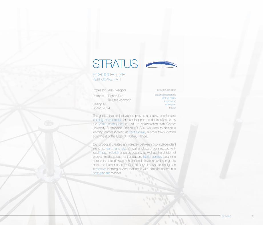
Professor | Alex Mergold
Partners | Renee Rust Takuma Johnson
Design IVSpring 2014
The goal of this project was to provide a healthy, comfortable learning environment for handicapped students affected by the 2010 earthquake in Haiti. In collaboration with Cornell University Sustainable Design (CUSD), we were to design a learning center located at Petit Goave, a small town located southwest of the Capital, Port-au-Prince.
Our proposal creates an interplay between two independent systems, earth and sky. A wall enclosure constructed with local masonry brick ensures security as well as the division of programmatic space; a translucent fabric canopy spanning across the site provides shelter and allows natural sunlight to enter the interior spaces. Our primary aim was to design an interactive learning space that dealt with climatic issues in a cost-efficient manner.
Design Concepts
elevated membranelight vs heavy
suspensionopen plan
tensile
STRATUS PETIT GOAVE, HAITI
STRATUS
SCHOOLHOUSE

8
A
B
C
Asite landscape local construction site entry
B C
ARNOLD SAN
Petit Goave, HaitiPopulation: 12,000Temperature (°C): 17 - 26Precipitation (inches): 2 - 9

9STRATUS
Index
1_Medical Center2_Toilets3_Classroom4_Entry5_Administration6_Library7_Conference Room8_Kitchen9_Eating Area10_Car Parking Closed Curtain Plan
SECURITY
Open Curtain Plan
SPACE
Water Drainage
SHELTER
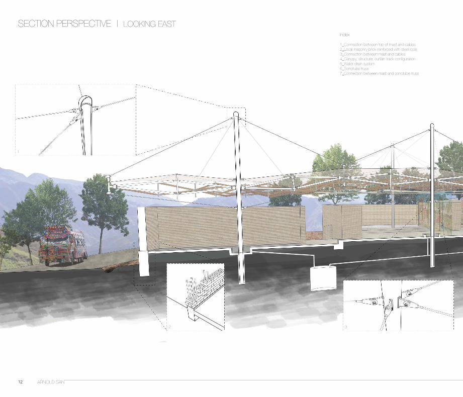
The canopy structure is suspended by six masts creating an open floor plan that is divided by a system of curtains. The tracks follow a triangulated grid formed by a series of prefabricated sonotube trusses. The top layer of fabric spans across the top of the trusses acting as a water barrier and light filter; the lower layer of fabric acts as a sound absorber and secondary light filter. Within the perimeter of the masonry walls, there are five arrangements of interior walls which house specific programmatic purposes such as storage and permanent divisions of space. The installation of a curtain track system allows flexibility in the usage of spaces, as well as circulation.
Roof Plan
10 ARNOLD SAN
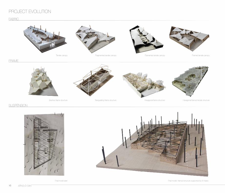
PROJECT EVOLUTION
FABRIC
Tensile canopy
Beehive frame structure
Final model plan Final model; framed structure supported by 6 masts
Triangulating frame structure Hexagonal frame structure Hexagonal framed tensile structure
Fragmented tensile canopy Framented tensile canopy Framed tensile canopy
FRAME
SUSPENSION

11
ORIGINAL SITE1. 2. 3. 4.
1. 2. 3. 4.
5. 6. 7.
ONE 40' SHIPPING CONTAINER ERECTING 6 MAIN STRUCTURAL MASTS
1. ERECT STRUCTURAL MASTS AND ANCHOR INTO CONCRETE SLAB
2. ATTACH END OF SONOTUBE TRUSS TO MAST AT WELDED JOINT
3. ERECT SONOTUBE TRUSS PERPENDICULAR TO MAST
4. ATTACH TOP CANOPY TO TOP ENDS OF STRUCTURAL STRUTS IN TRUSSES
5. HANG SECONDARY CANOPY FROM UNDERSIDE OF TRUSSES. CANOPIES MADE BY LOCALS ACCORDING TO TRADITIONAL METHODS AND PATTERNS
6. HANG METAL TRACKS FOR CURTAINS OFF OF UNDERSIDE OF TRUSSES. CURTAINS TO BE MADE BY LOCALS
ATTACHING SONOTUBES TO MASTS INDIVIDUALLY
CONNECTTING SONOTUBES TOGETHER TO FORM UMBRELLA SHAPED CANOPIES
JOIN "UMBRELLAS" TO EACH OTHER TO COMPLETE SPACEFRAME
STRETCH PVC COATED FABRIC ONTO TOP OF SPACEFRAME TO FORM TOP
SUSPEND METAL TRACKS AND CURTAINS FROM UNDERSIDE OF SPACEFRAME
CLEAR SITE LEVEL + TERRACE SITE LOCAL MASONS BUILD PERIMETER AND INTERIOR WALLS
LOCAL
BROUGHT TO HAITI
CANOPY CONSTRUCTION
FOR EACH TRUSS
FOUR 10' SONOTUBES 64 BOLTS
128 NUTS
128 WASHERS
ONE COMPRESSION STRUT
EIGHT END-CAP KNIFE PLATESTWO MIDPOINT CONNECTION PLATES
ONE CABLE ATTACHMENT PLATE
PVC COATED TOP CANOPY
SIX 40' TALL STEEL MASTS
STEEL CABLE
TRUSS CONNECTORS
STEEL FABRIC CONNECTOR RINGS
CABLE ANCHORS
STRATUS
CONSTRUCTION DIALOGUE
12 ARNOLD SAN
SECTION PERSPECTIVE | LOOKING EAST
1
2 3
Index
1_Connection between top of mast and cables2_Local masonry brick reinforced with steel rods3_Connection between mast and cables4_Canopy, structure, curtain track configuration5_Water drain system6_Sonotube truss7_Connection between mast and sonotube truss

13STRATUS
4 5
6
7

14 ARNOLD SAN
MATERIAL AND SYSTEM DIAGRAM
15STRATUS
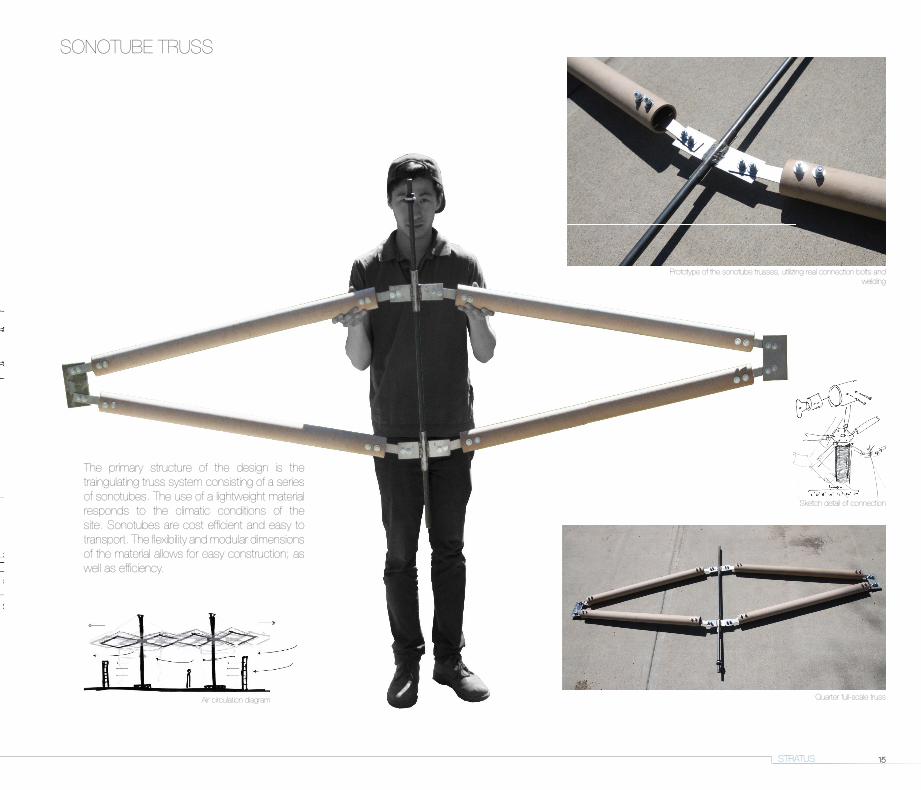
Sketch detail of connection
Air circulation diagram
SONOTUBE TRUSS
Quarter full-scale truss
Prototype of the sonotube trusses, utilizing real connection bolts and welding
The primary structure of the design is the traingulating truss system consisting of a series of sonotubes. The use of a lightweight material responds to the climatic conditions of the site. Sonotubes are cost efficient and easy to transport. The flexibility and modular dimensions of the material allows for easy construction; as well as efficiency.

16 ARNOLD SAN
Interior view of communal space
Rendered section Exploded axonometric seperating design components
RENDERINGS

17STRATUS
The project evolves from the central idea of the tent being one of the most basic embodiments of a community. It is cost efficient, energy saving, versatile, and directly linked with nature. Using a system of tensile fabric structure and a triangulating geometry of the sonotube framework, construction becomes easy to assemble while also allowing flexibility in design. Furthermore,having two separate systems of wall enclosure and shelter significantly reduces the risk of damage or casualties in the case of a seismic event.
View of South end of the site Eye-level view of truss canopy Detail of mast and trusses;
Half scale model of umbrella system View of connection details from trusses to mast
MODELS

18 ARNOLD SAN

19INSERT
Professors | Val Warke Danielle DuranteDesign VFall 2014
The primary objective of this project was to create a multi-functional transit hub with a parking garage that can accomodate more than 120 vehicles. The site is located at Valle Aurelia, around 300 meters east of the Vatican.
My final design is an elevated structure inserted between the existing overhead train railway and the old railway. A linear volume space runs along the same axis as the existing overhead railway, while extrusions branch out at specified points of the site. These additional extrusions respond to the topographical conditions of the site, i.e. bus stop locations, ascending slope of the hill.
Design Conceptsinsertion/extrusionelevated structure
accessibility transparency
linear axis
INSERTVALLE AURELIA, ROMETRANSIT HUB

20
A B C
A
B
C
SITE INVESTIGATION
ARNOLD SAN
Old and existing railways Valle Aurelia metro station Existing parking garage
Valle Aurelia, Rome
Main circulation systems on site:- Underground station on line A of the Rome metro system and the mainline station - Mainline station for the regional railway FR3- Main Highways; Via Angelo Emo and Via Baldo degli Ubaldi

INSERT 21
Automobile
Building height elevations in relation to surrounding context
Visual and circulation axis Exploded axonometric showing different modes of circulation
Pedestrian/Cyclists
Overhead train
Old railway
Metro
Multiple site visits to Valle Aurelia allowed us to clearly dissect the various systems which the site had to offer. The site is composed of a series of different transit circulation arrangements which all intersects at a pivot point on the site, the train station. Our objective was to identify the different modes of transportation, the varying movement and density levels at specified locations; as well as the topography, green vs. dead space, local neighbourhood and the range of programs across the site.

22
2. Section across train staion
3. Section across terraced descend
1. Section across underground pedestrian tunnel
SURROUNDING CONTEXT
ARNOLD SAN
Pressures from neighbouring communities
Section cut parallel to overhead railway;showing different modes of circulation
commercail
dead space
residential
public park
residential
unkept fabricatednatural vegetation
Pressure from currently supressed green spaces and landscape
23
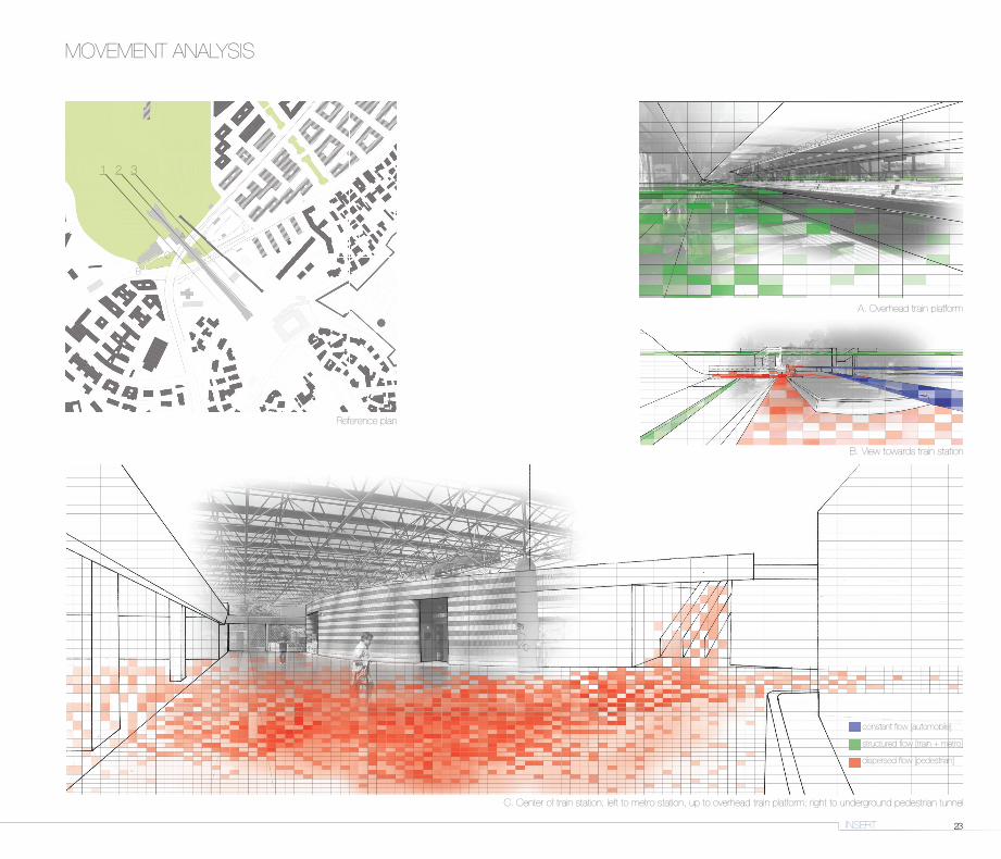
B. View towards train station
Reference plan
A. Overhead train platform
C. Center of train station; left to metro station, up to overhead train platform; right to underground pedestrian tunnel
constant flow [automobile]
structured flow [train + metro]
dispersed flow [pedestrian]
MOVEMENT ANALYSIS
INSERT
1
A
2
B
3
C

24 ARNOLD SAN
Existing transportatoin hubs
GLASS
PERFORATED STEEL
Opposing hillsResidential neighbourhood The Vatican
Site plan with highlighted context
Inserted between the train station and parking garage, the building acts as a mediator between the pressures exerted from the residential neighbourhood and the opposing hills.
The project aims to establish a sense of community within the area, without disrupting the visual transparency through the site. The duality of glass and perforated steel allows the user to experience a gradient of visual permeability.
SECTION PERSPECTIVE | LOOKING WEST

25
1
4
5
6
3
2
6
2
6
6
7
Index
1_Existing metro station2_Existing train station3_Existing parking garage4_Terraced public space5_Viewing tower6_Elevator shafts7_Parking garage
Visual transparency; elevated structure
Integration of existing old railway
Connection from ground level to elevated platform
Adaptation to existing slopeGround and top level plans
INSERT

26
PARKING GARAGE
The parking garage is located on the south end of the existing carpark area; it is inserted between the piers of the old railway. The structure forms a connection from the ground level to the main volume, which is also connected to the existing train platform. The use of perforated steel as the structure's facade allows for visual transparency as well as ambient sun light exposure. The three-storey parking garage can accomodate 40 vehicles on each level, doubling the parking capacity of the existing carpark.
A. Interior view of parking garage
Parking garage ground floor plan
ARNOLD SAN
A
B

27
B. Exterior view of inserted structure
INSERT

28 ARNOLD SAN
MASSING
Interverntion as mediator
Bird's eye
Surrounding pressures
DIAGRAMS | MODELS
STRUCTURE MATERIAL CIRCULATION

29INSERT
View of parking garage inserted between the railway piers
Isolated view of structure
Folding structure
The linear form of the intervention mimics that of the existing railway infrastructure. Using a folding system of walls, the structure creates a series of extrutions and voids, blurring the distinction between indoor and outdoor, The combination of the folding structure, the use of transparent material, and flexibile accessibility creates an inviting spatial intervention that would improve the social dynamics of the area.

30 ARNOLD SAN

31TRANSFORM
Professor | Val Warke Jim WilliamsonDesign IISpring 2013
The first phase of this project was to analyse and re-interpret Jose Oubrerie's Miller House. My analysis began by extract-ing the formal components of the structure: the column grid, heirarchy of spaces, the facade and circulation. The next step was to perform interpretive operations on these components with the intent of emphasizing, identifying, and extrapolating the precedent's main concepts.
Later into the project, I had to create a hybridization with the Hemeroscopium House designed by Ensamble Studio, ap-plying its L-shaped structural system into my final design.The final phase was to design a retreat for 6 writers to rest, think and cleanse themselves.
Design Conceptscolumn grid
circulationlevitationL-shape
TRANSFORMANALYTICAL INTERPRETATION

32 ARNOLD SAN
Miller House: structural floor plans; nolli plan highlighting circulationMiller House: axonometric plans
level 1 level 2
level 3 Nolli plan
PRECEDENT ANALYSIS
My analysis identified the main formal components ofthe Miller House through drawings and 3D representations. The Miller House consists of three primary volumes of space; two bedrooms and one larger master bedroom. The volumes are organized via a four by four column grid that forms a heirarchy of spaces. Circulation is dictated by a series of pathways and bridges that navigates through and around the column grid. The facade of the MIller House is detached from the main occupiable space, acting as a physical and symbollical mediator between exterior and interior.

33TRANSFORM
Hemeroscopium House
Isolating formal components
facade + structure design concept
Miller House . facade Hemeroscopium House: structureMiller House
1. Precedent analysis
2. Chimerical operations
4. Final tranformation for retreat
3. Hybridzing components
Retreat complex accomodating 6 writersInterpretive operation Hybridization
1. Precedent analysis
2. Chimerical operations
3. Hybridzing components
TRANSFORMATION
Plan
Front elevation

34 ARNOLD SAN
AB
AB
A-A Section cut
B-B Section cut Level 1
Level 2
Site plan

35TRANSFORM
Exterior view [day]
Bird’s eye
Exterior view [night] Design process; exploded components
The site for the retreat is located on a sloping hill with a stream that leads to an old mill and a lake. Structure, circulation and occupiable space are organized using components from the hybridization. The goal was to create a complex of floating vestibules that are interconnected by a series of ramps regulated by the column grid.
Study models of hybridizing components

36 ARNOLD SAN

37BODY ARMOUR
Professor | Val Warke Jim WilliamsonDesign IFall 2012
This project began by an analysis of a given object, an apparatus designed and engineered to protect a specific part of the body, in my case, a shin pad. We were to dissect the body armour, producing a documentation of the object's different attributes; form, material, construction, performance, and function.
The next phase was to re-construct the object in a new form that incorporates its functional attributes. My reconstruction aims to explore the joint connection and its movement capacity in a linear system.
Design Conceptsmotion
jointtorque
radial movement
ANALYTICAL INTERPRETATION
BODY ARMOUR

38 ARNOLD SAN
Exterior hard shell Secondary protective cushion
DISSECTION
Body armour: hockey shin padShin pad cushion components
The dissection process allowed me to isolate the different functional components of the body armour. The shin pad is composed of three main layers: the protective shell, the primary cushion, and the secondary cushion, The form of the shin pad reflects the functional qualities of a human leg.
My approach to the reconstruction primarily dealt with the physical relationship between the body armour and the human body. The radial motion of the leg joint is conveyed through the physical form and flexibility of the shin pad. My final model aimed to mimic the organic motion of a moving leg.

39
Primary protective cushion Isolating knee protective gel
BODY ARMOUR

40 ARNOLD SAN
Abstraction of the leg’s organic motion in relation to the body armor
RECONSTRUCTION

41BODY ARMOUR
Interactive model replicating joint movement of the knee
Final model . reconstruction of body armour
Detail on joint connections Moving capacity of structure
Diagram showing reconstruction's components
Radial movement conveyed through joint mechanism

42 ARNOLD SAN

43AEDAS
AEDAS
Summer 2014Project team: Wai Tang
During my internship at Aedas, I had the opportunity to work with 4 urban design and masterplanning projects located in China. My primary involvement included making schematic designs, facade studies, and constructing analytical diagrams. I was also involved in an office interior design project and had the chance to design the interior of an elevator cab.
PROFESSIONAL INTERNSHIP

44
Sections
GF retail street sections
BA CSunken plaza section
Professional rendering
ARNOLD SAN
FOSHAN GREENLAND CENTERProject: Greenland Center ProjectLocation: Foshan, China Sector: Urban Design & Masterplanning Discipline(s): ArchitectureProject Supervisor: Luke Lu
Overview
Design Concept:
. Landmark of Foshan City Axis
. Relation to neighbouring cities
. Responding to local history and culture
. Distribution of different programs
Responsibilities
. Photoshop/Illustrator diagrams
. Section cuts
. Axon circulation diagrams
. Indesign presentation editting
. Reference images

45
Anchor store
Access to L2Courtyard
Anchor store
Access to L1
Courtyard
Courtyard
Courtyard
High Street
Axonometrics
Sunken plaza
Art centre
Anchor store
Smaller shops
F&B
Retail street entranceCommercial plaza
Vertical Circulation
High Street: ground and 2nd level
Traditional Southern Canton Retail Street; ground and 2nd level
MasterplanMasterplan
AEDAS
BC
A
Overview
Design Concept:
. Landmark of Foshan City Axis
. Relation to neighbouring cities
. Responding to local history and culture
. Distribution of different programs
Shop Front
Main Circulation

46
Project: Greenland East VIllage Project Plot 5Location: Chengdu, China Sector: Urban Design & Masterplanning Discipline(s): ArchitectureProject Supervisor: Phyllis Wong
Overview
Design Concept:
. Old vs New
. Manipulation of exterior facades
. Physical and visual connectivity
. Multi-level circulation
Responsibilities
. Constructing a physical model
. Photoshop rendered images
. Rhino model touchups
1:50 Partial model: comparing different sizes of fin panelsShopping complex
Professional rendering
CHENGDU GREENLAND EAST VILLAGE PLOT 5
ARNOLD SAN
Responsibilities

47
Project: Greenland East VIllage Project Plot 5Location: Chengdu, China Sector: Urban Design & Masterplanning Discipline(s): ArchitectureProject Supervisor: Phyllis Wong
West elevationMulti-level circulation
South elevation
North elevation
AEDAS

48
Overview
Design Concept:
. Individual vs communal
. Hard vs soft
. Visual connection
. Promoting social interaction
Responsibilities
. Making a new rhino model from given floor plans
Professional rendering
ARNOLD SAN
Project: Greenland East VIllage Project Plot 9Location: Chengdu, China Sector: Urban Design & Masterplanning Discipline(s): ArchitectureProject Supervisor: Phyllis Wong
Responsibilities
CHENGDU GREENLAND EAST VILLAGE PLOT 9

49
2F
1F
3F80
100
80004100850085008500850062851020068006800
1040
085
0085
0010
200
8500
8500
8500
85200
6400
8500
8500
8500
8500
8500
8500
1020
085
0010
400
8500
85008500
85008500
85008500
85008500 76500
7160
0
7000
5500
8500
10941
663
84°°
557
7
5a
6 8
6a4a
4 93
12a
2 111
3a
9a 10a
10
8a
5
11a
12
2a
7a
H
L
J
F
K
N
D
L
M
E E
A
G
N
C
F
C
G
B
H
B
M
J
K
A
2F
1F
3F
8010
0
80004100850085008500850062851020068006800
1040
085
0085
0010
200
8500
8500
8500
85200
6400
8500
8500
8500
8500
8500
8500
1020
085
0010
400
8500
85008500
85008500
85008500
85008500 76500
7160
0
7000
5500
8500
10941
663
84°°
557
7
5a
6 8
6a4a
4 93
12a
2 111
3a
9a 10a
10
8a
5
11a
12
2a
7a
H
L
J
F
K
N
D
L
M
E E
A
G
N
C
F
C
G
B
H
B
M
J
K
A
AEDAS
level 3
level 2
level 1
Perspective
Roof Plan
Inner facade perspective

50
Overview
Design Concept:
. Iconic landmark tower
. Irregular rhythm of vertical fins
. Shifting volumes
. Subdivision of blocks in relation to
. programmatic use and ownership
Responsibilities
. Photoshop lobby renders
. Spatial analysis diagrams
. Reference images for lobby interior
. Lighting diagrams
. Elevator cab design: plan/section diagrams + 3D render. Acquiring material information + samples
Responsibilities
Professional rendering
ARNOLD SAN
Project: Guangdong Bravo Pazhou ProjectLocation: Guangzhou, China Sector: Office Discipline(s): ArchitectureProject Supervisor: Phyllis Wong
GUANGDONG BRAVO PAZHOU
Access to elevatorsEscalator entry Main lobby Elevator waiting area

51
Brass coloured stainless steel
Brushed brass
Tan Brown Granite Stone
Mirror surface
14251425
2850
200
2450
3000
1000
Brass coloured stainless steel
Brushed brass
Tan Brown Granite Stone
Mirror surface
14251425
2850
200
2450
3000
1000
Brass coloured stainless steel
Brushed brass
Tan Brown Granite Stone
Mirror surface
14251425
2850
200
2450
3000
1000
Brass coloured stainless steel
Brushed brass
Tan Brown Granite Stone
Mirror surface
14251425
2850
200
2450
3000
1000
Brass coloured stainless steel
Brushed brass
Tan Brown Granite Stone
Mirror surface
14251425
2850
200
2450
3000
1000
Brass coloured stainless steel
Brushed brass
Tan Brown Granite Stone
Mirror surface
14251425
2850
200
2450
3000
1000
Brass coloured stainless steel
Brushed brass
Tan Brown Granite Stone
Mirror surface
14251425
2850
200
2450
3000
1000
Brass coloured stainless steel
Brushed brass
Tan Brown Granite Stone
Mirror surface
14251425
2850
200
2450
3000
1000
Brass coloured stainless steel
Brushed brass
Tan Brown Granite Stone
Mirror surface
14251425
2850
200
2450
3000
1000
AEDAS
Project: Guangdong Bravo Pazhou ProjectLocation: Guangzhou, China Sector: Office Discipline(s): ArchitectureProject Supervisor: Phyllis Wong
Interior rendering of elevator cab
Elevator Plan Elevator interior elevations

52 ARNOLD SAN
Thank youThank youThank youThank youThank you