army equipment - 2320-d-122-522 support publication · 25 assembling rear bearing, scroll plate and...
TRANSCRIPT

ARMY EQUIPMENT - 2320-D-122-522
SUPPORT PUBLICATION
Chapter 11-1,
DIESEL FUEL SYSTEM
CONTENTS
Frame Para
1 Introduction DPS Fuel injection pump
2 Removal Dismantling
3 Special tools 4 Timing cover plate 5 Excess fuel linkage spring 6 Throttle control bracket and solenoid 7 Back leakage adaptor 8 Throttle lever. assembly 9 Vent screw 10 Governor control cover 11 Throttle shaft assembly 12 Governor arm and control bracket 13 End plate and regulating valve 14 Delivery valve assemblies 15 Transfer pump 16 Automatic advance mechanism 17 Latch valve 18 Rotor vent switch valve 19 Hydraulic head 20 Pump housing and drive shaft assembly
Cleaning and examination 21 General 22 Mated parts 23 Examination
Reassembly 24 Drive shaft 25 Governor weight assembly 26 Pump housing and drive shaft assembly 27 Checking drive shaft end float 28 Drive shaft oil seal • 29 Rear bearing, cam and scroll plates 30 Hydraulic head 31 Automatic advance housing assembly 32 Latch valve assembly 33 Rotor vent switch valve 34 Transfer pump 35 End plate and regulating valve assembly 36 Governor arm control bracket assembly 37 Governor control cover 38 Idling shaft and lever 39 Excess fuel shaft 40 Throttle shaft and anti-stall components 41 Maximum fuel adjustment screw 42 Vent screw 43 Throttle lever assembly 44 Back leakage adaptor 45 Delivery•valve assemblies 46 Solenoid assembly 47 Timing cover plate 48 Throttle control bracket 49 Excess fuel linkage
Oct 90 Chap 11-1 Page 1

2320-D=122-522
CONTENTS (Cont'd)
Frame Para
Test plan 51 General 52 Test conditions 53 Setting excess fuel mechanism
ISO Test procedure 54 Preparation 55 Test 56 Refitting
Fuel injectors 57 Special tools . .
CheckihghOzzle ansemblies‘ONARNEW 58 General 59 Spray check 60 Removal 61 Dismantling 62 Cleaning and examination 63 Reassembly ,
Testing 64 General 67 Test procedure (WARNING) 68 Refitting
Fuel lift pump. 69 Removal 70 Dismantling 71 Cleaning 72 Examination 73 Reassembly 74 Testing 75 Refitting
Fuel tanks (WARNINGS) 76 General
Removal 77 Side mounted fuel tank 78 Rear mounted fuel tank
Refitting 79 Side and rear fuel tanks
Fuel leveI,unit', Removal
80 Side mounted fuel tank 81. Rear mounted fuel tank 82 Refitting
Fuel sedimenter 83 General 84 Removal/Befitting'85. Cleaning 86 Fuel filter 87 Prime fuel system 89 Throttle pedal adjustment
Table
1 Special tools 2 Fuel pump testing
Fig.t
1 DPS_. pump removal. 2 DPS pump timing pulley retaining tool
Chap 11-1 P7AgO: 2
AMY EQUIPMENT" SUPPORT PUBLICATION
Page
4 60
6
Oct 90

ARMY EQUIPMENT 2320-D-122-522 SUPPORT PUBLICATION
CONTENTS (Cont'd)
Frame Fig Page
3 Throttle control bracket, solenoid and timing cover plate assembly 7
4 Location of linkage spring 8 5 Throttle lever, vent screw and pressurising vzlye 10 6 Governor control cover 12 7 Governor control linkage 14 8 End plate and regulating valve assembly 15 9 Delivery valve assemblies 16 10 Transfer pump 17 11 Slackening transfer pump rotor 18 12 Advance housing assembly 19 13 Slackening the cam advance screw 20 14 Latch valve assembly 21 15 Rotor vent switch valve 22 16 Pump housing, drive shaft assembly and hydraulic head 23 17 Removing drive end oil seal 24 18 Removing pump housing from drive shaft 25 19 Timing disc and drive shaft etching locations 26 20 Drive shaft assembly 28 21 Governor weight assembly 29 22 Pump housing and drive shaft assembly 30 23 Checking drive shaft end float 32 24 Fitting drive shaft oil seal 33 25 Assembling rear bearing, scroll plate and cam ring 34 26 Exploded view of hydraulic head 35 27 Method of tightening rotor plug screw 36 28 Rear scroll plate and hydraulic head 37 29 Inserting the hydraulic head 38 30 Tightening the cam advance screw 39 31 Advance housing assembly 40 32 Latch valve assembly 42 33 Rotor vent switch valve 43 34 Tightening transfer pump rotor 44 35 Fitting rotor liner and head bracket 45 36 End plate and regulating valve 46 37 Fitting the end plate assembly 47 38 Assembling the governor control linkage 48 39 Assembled governor control linkage 49 40 Setting the governor linkage 50 41 Governor control cover 51 42 Fitting the governor control cover 53 43 Throttle lever assembly, vent screw and pressurising valve 55 44 Throttle control bracket, solenoid and timing cover plat 57 45 Location of linkage spring 58 46 Refitting the DPS pump 63 47 Timing tool inserted in DPS pump 64 48 Fuel injector spray check on engine 65 49 Removal of injectors from cylinder head 66 50 Exploded view of fuel injector 67 51 Cleaning fuel passages 68 52 Cleaning nozzle 69 53 Flushing tool 70 54 Leak back test. 72 55 Spray check rig 73 56 Spray form 73 57 Removing fuel lift pump upper casing 75 58 Removing valves from upper casing 76 59 Diaphragm assembly removal 77
Oct 90 -chap 11-1 Page 3

2320-D-122-522
CONTENTS (Cont'd) Frame Fig
60 Removing rocker. arm 61 Side mounted fuel tank removal 62 Rear mounted fuel tank removal
ARMY EQUIPMENT SUPPORT PUBLICATION
77 80 81
INTRODUCTION
1 This Chapter details the Unit and Field repairs for the Fuel System fitted to Land Rover 90 and 110 vehicles with 2,5 litre diesel engines.
TABLE 1 SPECIAL TOOLS
Ser No (1)
Manufacturers Part No (2)
NSN/Part No where applicable
(3)
Designation
(4)
1.. . 18G •1457 6MT2/5120-a91-7-25-6475r.. ,, DIPS, pumpAemoving tool -2 18G 1458 6MT2/5120-99=725=6476 DPS"'pump'timing tool 3 LST 107 Flywheel timing pin 4 RO 600964 - Spanner, fuel tank unit
DPS FUEL INJECTION PUMP
Removal
2 To remove the DPS fuel injection pump proceed as follows:
2.1 Disconnect the battery leads and where applicable the leads from the radio batteries.
2.2 Refer to Chap 1 Para 59 and insert the flywheel timing pin (Table 1 Serial No 3).
2.3 Disconnect the fuel feed pipes (Fig 1 (1)) at the deliyery valves (2) and.at.the fuel. injectors and remove..
2.4 Disconnect the fuel inlet pipe (3), spill return pipe (4) and the electrical connection (5) from the solenoid.
2.5 Remove the oil filter adaptor assembly (6) to provide clearance for the pump to be drawn rearwards.
2.6 Remove the nut and bolt (7) securing the rear end of the pump to the support bracket (8).
2.7 Disconnect the throttle linkage at the ball pin (9) on the throttle lever.
2.8 Remove the inspection plate (Fig 2 (1)) from the front. cover (2).
2.9 Using a suitable socket spanner, remove the nut (3) securing the pump pulley to the drive shaft (4).
- 240'..klitaimoyefAhertwoitront:voYer-securing-430,1 5P6:411124t*itwit2uihose,elip.:.;,,.„:;_. (6) and fit the outer part of special tool (7) (Table 1 Serial Miter 1). When fitting the special toolitwo.pkairt washers, must be. inserted, between the tool and the cover to compensat for th gap.
chap 11-1 Oct 90 - Page 4

ARMY EQUIPMENT SUPPORT PUBLICATION
2320-D-122-522
1 Fuel feed pipes 6 Oil filter adaptor
2 Delivery valves 7 Nut and bolt
3 Fuel inlet pipe 8 Support bracket
4 Spill return pipe 9 Ball pin-throttle lever
5 Solenoid electrical connection 10 Securing nuts
Fig 1 DPS pump removal
2.11 Fit the centre part of the special tool and screw the 'Allen' screws
into the DPS pump pulley. To centralise the tool adjust the thre side
screws
2.12 Slacken off, but do not remove, the three nuts (Fig 1 (10)) securing
the pump to the rear casing.
2.13 Screw in the centre bolt of the special tool in a clockwise dir ction
to release the pump from the pulley. Remove the three securing nuts and
withdraw the pump from the engine. Discard joint gasket.
2.14 Slacken off the centre bolt and leave the tool in position until the
pump is refitted.
Dismantling
Special tools
3 Special tools for overhauling and testing the DPS injection pump are listed
in AMP 2910-F-101-302 and ETS 06009.
Note ...
Before commencing dismantling, clean the exterior of the pump using a
suitable proprietary cleaning fluid or kerosene.
Oct 90 Chap 11-1
iPag 5

2320LP-112-522
1 Inspection plate 2> Frontitoyer,, 3 Nut-pulley retaining 4 Drive shaft
ARMY EQUIPPIENT SUPPORT PUBLICATION
5 Securing bolts •
-7' • Special.' tool •
Fig 2 DPS pump -timing pulley'retaining tool
Timing cov r plate
4 Tb remove the timing cover plate proceed as follows:
4.1 Turn the pump on its side, timing cover plate (Fig 3 (14)) uppermost.-
4.2 Loosen the plug (16) and using special tool bit CAV Part Number 7244-438 and a suitable socket, remove the two `Tore screws (17), shakeproof washers (18) and cover plate (14) from the pump housing (12). Discard the shakeproof washers (18).
Note ...
•Sitimei4arliero :pumpss--.Weree:fitted:ftiith'socket•Iiiitrsbtetia-' RetioNfe.-usi special tool CAV Part , Number 7244-249.:
Chap A-1 'Page 6
Oct 90
•

ARMY EQUIPMENT SUPPORT -PUBLICATION
2320-D-122-522
4.3 Remove the plug (16) from the cover plate (14), detach and discard the `0' ring seal (15).
4.4 Remove and discard the '0' ring seal (19) from the recess in the pump housing.
4.5 Invert the pump and drain any remaining fuel into a suitable container.
LR413OM
1 Anti-stall screw 8 Plunger 17 'Torx' screw washer and locknut 9 Support bracket 18 Shakeproof washer
2 Max. speed screw 10 NUt-support bracket 19 '0' ring seal and locknut 11 Governor control cover 20 Vent screw
3 Throttle control 12 Pump housing 21 Washer bracket 13 Mounting fixture 22 Spring washer
4 Throttle lever 14 Timing cover plate 23 Set bolt 5 Solenoid• 15 '0' ring seal 6 '0' ring seal 16 Plug screw-cover 7 Spring plate
Fig 3 Throttle control bracket, solenoid and timing cover plate ass mbly
Oct 90 Chap-11-1 Page 7

2320=6-122-522
Excess fuel linkage spring
Note ...
ARMY EQUIPMENT'.SUPPORT PUBLICATION
To prevent undue loading on the excess fuel shaft, it is important to remove the linkage spring from the excess fuel plate pin before removing the throttle control bracket.
5 To remove the excess fuel linkage spring carry out the following:
5.1 Slacken the locknut (Fig 4 (7)) on the linkage spring stud (6). Push the long leg of the break-back spring (4) away from the excess fuel plate pin (2).,
5.2 Using the special hook tool, CAV Part Number 7244-405, unhook the long nd of the linkage spring (3) from the pin (2).
1 Eicest-tuel:.shaft-e"- .:- - S--ThtcAti ker.:' 2 Pin-excess fuel plate 6 Stud-linkage spring 3 Linkage spring 7 Locknut 4 Break-back Spring- •
Fig 4 Location,of linkage spring.
Throttle control bracket and solenoid
6 To remove the throttle control bracket and solenoid proceed as follows:
6.1 Secure the pump housing (Fig 3 (12)) to the mounting fixture (13) CNV Part Number 7244-200 and clamp the fixture in a suitable vice with the governor control cover (11) uppermost.
Chap 11-1 ,Page 8
Oct 90

ARMY EQUIPMENT 2320-D-122-522 SUPPORT PUBLICATION
6.2 To allow removal of the throttle control bracket (3), r strain the throttle lever (4) in-situ against the compression of its spring by pulling back the lever from the anti-stall screw (1) and fitting an llmm socket over the vent screw (20). Release the lever when the socket is in position.
6.3 Remove the two set bolts (23), spring washers (22) and plain washers (21) and detach the throttle control bracket (3) from the governor control cover (11).
6.4 Unless the bracket is to be renewed, it should not be necessary to remove the anti-stall screw, washer and locknut (1) or the maximum speed screw and locknut (2).
6.5 Remove the solenoid (5) from the hydraulic head complete with the plunger (8) and spring (7). Remove and discard the 'Co' ring seal (6) from the solenoid.
Note ...
The solenoid plunger and body are a matched assembly and should not be separated.
Back leakage adaptor
7 Pull the idling lever (Fig 6 (1)) clear to allow access to the back leakage adaptor, unscrew and remove the adaptor (Fig 5 (20)) from the governor control cover (13).
Throttle lever assembly
8 To dismantle the throttle lever assembly proceed as follows:
Note ...
Before dismantling the lever assembly, check that the top face of th indexing plate has been stamped with the letter 'X'. If not, mark th plate with a letter 'X' so that it can be re-fitted in the same position.
8.1 Remove the set bolt (1), spring washer (2) and plain washer (3) from the boss on the throttle lever assembly (5).
8.2 Unscrew the self locking nut (27) one complete turn. Then, while restraining the throttle lever against compression of the spring (10), remove the llmm socket previously fitted to the vent screw body (16) and release the spring tension on the lever lifting the lever clear of the idling shaft. Detach the short end of the spring (7) from the linkage spring stud (18).
8.3 Remove the self locking nut (27) from the throttle shaft (12) and detach the plain washer (26) and indexing plate (4).
8.4 Remove the throttle lever assembly (5) from the shaft with spring (10) and then remove the short leg of the spring from the lever. Remove the cap washer (8) and packing ring (9) from the shaft (12).
8.5 Remove the throttle lever assembly (5), the locknut with int gral `Belleville' washer (21), plain washer (22) and ball pin (23). Remove the self locking nut (25), plain washer (24) and stud (18).
Oct 90 Chap 11-1 .Page 9

2320- D422-522 ARMY EQUIPMENT SUPPORT PUBLICATION
—8
9
-10
11
12
13
Fig 5 Throttle lever, vent screw and pressurising valve • E -
Chap 11-1 Page 10
Oct 90

ARMY EQUIPMENT SUPPORT PUBLICATION
Key to Fig 5
2320-D-122-522
1 Set bolt 15 Copper washer 2 Spring washer 16 Vent screw body
3 Plain washer 17 Vent screw 4 Indexing plate 18 Stud-linkage spring
5 Throttle lever assembly 19 Washer
6 Break-back spring 20 Back leakage adaptor
7 Linkage spring 21 Locknut with compressible washer
8 Cap washer 22 Plain washer 9 Packing ring 23 Ball pin 10 Throttle lever spring 24 Plain washer 11 '0' ring seal 25 Self locking nut
12 Throttle shaft 26 Plain washer 13 Governor control cover 27 Self locking nut
14 Boss and pin-excess fuel plate
8.6 Check the condition of the break-back spring (6), if it is n cessary
to remove the spring from the throttle lever (5), squeeze both ends of the
spring together then prise the coiled end of the spring from the locating
pin.
Vent screw
9 Slacken the vent screw (17), unscrew and remove the vent screw body (16)
from the governor control cover (13) and discard the copper washer (15).
Governor control cover
10 To remove the governor control cover carry out the following:
10.1 Remove the locknut (Fig 6 (23)), the maximum fuel adjustment screw
(24) and the rubber sealing washer (22) from the governor control cover
(14). Discard the sealing washer.
10.2 Remove the excess fuel shaft (17) the self locking nut (7), plain
washer (8), plate (9) and plain washer (10).
10.3 Remove the locknut (4), and shakeproof washer (3) from the idling
shaft (20), detach the idling lever (1), complete with idling adjustment
screw and locknut (2), spring (5) and spring guide (6), discard the
shakeproof washer.
10.4 Using socket adaptor CAV Part Number 7244-249, remove the four
hexagon socket screws (12) together with washers (13).
10.5 Lift the governor control cover (14) away from the pump housing and
at the same time, push down on the threaded end of the throttle shaft
assembly (19), the shaft must be pressed through the cover to remain
connected to the governor spring.
10.6 Push out the excess fuel shaft (17) and idling shaft (20) from the
governor cover, remove the '0' ring seals (16) and (22) from the shafts and
discard. Remove and discard the 'Ce ring seal (11) and the governor cover
rubber seal (15).
• Oct 90 Chap 11-1
Page 11

2326±D122-522 • ARMY EQUIPMENT SUPPORT PUBLICATION_
19
32 31 • 30 29 28 27 26 25
L.R4133M
1 Idling. lever 12 Hexagon socket screw 23 Locknut 2 Idling adjustment 13 Washer 24 Max. fuel adjuster
screw and-locknut, 14 Governor control cover screw 3 Shakeproof washer 15 Rubber seal 25 End plug 4 Locknut 16 '0' ring seal 26 Governor arm 5 Return spring 17 Excess fuel shaft 27 Pivot ball washer 6 Spring guide 18 '0' ring seal 28 Plain washer 7 S if locking nut 19 Throttle shaft 29 Buffer spring 8 Plain washer assembly 30 Anti-stall spring 9 Excess fuel plate 20 Idling shaft 31 Spring abutment 10 Plain washer 21 '0' ring seals 32 Plain Washer 11 '0' ring seal 22 Rubber washer 33 Self locking nut
Fig.. 6 ,Governor,, control. cover; :
Chap 11-1 Page 12
Oct 90

ARMY EQUIPMENT 2320-D-122-522 SUPPORT PUBLICATION
Throttle shaft assembly
Note ...
The throttle shaft assembly is a pre-loaded pack and should not be dismantled.
11 To remove the throttle shaft assembly proceed as follows:
11.1 Remove the self locking nut (33) from the threaded end of th end plug (25) and whilst restraining the end plug, remove the washer (32), spring abutment (31), anti-stall spring (30), buffer spring (29), plain washer (28), and pivot ball washer (27).
11.2 Pull out the end plug (25) with the throttle shaft assembly (19) from the governor arm (26). Remove and discard the '0' ring seal (18) from the shaft.
Governor arm and control bracket
12 To remove the governor arm and control bracket proceed as follows:
12.1 From the control bracket (Fig 7 (20)) remove the scroll link plate spring retainer (7), spring (6), sleeve (8) and spacer (9). Discard the spring retainer (7).
12.2 Unlock both tab washers (18), tab washer (10), and remove studs (19)
and hexagon headed screw (11). Discard all tab washers. Using special tool CNV Part Number 7244-247 remove the hexagon 'Panhead' screw (16).
12.3 Lift off the control bracket (20) complete with governor arm (21), metering valve (15) and spring linkage assembly. Detach the met ring valve
from the linkage hook (13) and immerse in clean test oil.
12.4 Disengage the control bracket (20) from the governor arm (21) and dismantle the governor spring linkage from the governor arm in th following order:
12.4.1 Remove the self locking nut (1), the linkage nut (2), washer
(3) and pivot ball washer (4) from the governor linkage arm (13).
12.4.2 Slowly release the compression on the linkage spring (12) and
disengage the linkage hook from the governor arm (21) taking care not to
lose the washer (5).
12.4.3 Slide the spring (12) and spring retainer (14) from th linkage
hook (13).
12.5 Using special tool CNV Part Number 7244-247, remove the two hexagon
`Panhead' screws and detach the idle actuator and guide bracket (22) from
the pump housing.
End plate and regulating valve
13 To remove the end plate and regulating valve carry out the following:
13.1 Using special tool CAV Part Number 7244-401, remove the four bracket
support nuts (Fig 3 (9)) and detach the support bracket (10) from the
delivery valve holders.
13.2 Slacken the fuel inlet connection (Fig 8 (15)) in the end plate (7).
Oct 90 Chap 11-1 -Page 13

232061122-522
1 Self-locking nut -2 Linkage nut 3 Washer 4 Pivot ball washer 5. Washerrainkage:sOingr,... 6 - Spiing..Scroll- linkild.ati 7 Spring retainer 8 Sleeve 9 Spacer 10 Tab washer • 11 Hexagon headed screw
-12...--Spring-governor..linkage.
ARMY. EQUIPMENTSUPPORT PUHLICAT/134
13 Linkage hook 14 Spring retainer 15 Metering valve 16 IPanhead' screw 17,1 Ec4ollainikdplate.
-,7vib, ;Nigher •
19 Stud-control bracket 20 Control bracket 21 • Governor 'ant.22 - Idling actuator and
guide bracket with 'Panhead' screws
Fig-7 Governor control linkage
13.3 Unscrew the four hexagon headed screws end plate (7) from the hydraulic head (9).
13.4 Remove the fuel inlet connection (15), washer (14).
(6) and carefully remove the
remove and discard the copper
• • •
13.5 Invert the end plate. (7). and remove .the sleeve. retaining spring, (12), , transferliceissure4djuitet*Itinieftlter tan: .Spriritkaiiektieg4460emblyr(111yt - • • ••
regulating sleeve (3), piston (2), and piston retaining spring (5). Discard the sealing wash r` (4).
ChapJ1 -1 .:,..page 14
Oct 94

ARMY EQUIPMENT SUPPORT PUBLICATION
10
23201)-122-,522
LR4135M
1 spring and peg assembly 9 Hydraulic head 2 Regulating piston 10 Socket screw 3 Regulating sleeve 11 Transfer pressure adjuster 4 Sealing washer 12 Spring-retaining sleev 5 Spring-piston retaining 13 Filter 6 Hexagon headed screw 14 Copper washer 7 End plate 15 Fuel inlet connection 8 Hydraulic head bracket
Fig 8 End plate and regulating valve assembly
13.6 Using socket adaptor CAV Part Number 7244-250 or a suitable alternative, remove the four socket head screws (10) and detach the hydraulic head bracket (9).
Delivery valve assemblies
14 Remove the banjo assemblies from the hydraulic head as follows:
14.1 Slacken and unscrew the banjo bolts (Fig 9 (11)) and remov each of
the complete banjo assemblies (1) from the hydraulic head (2) noting their
position and type relative to the letter of identification of the outlet
holes. Discard the sealing washers (10).
Oct 90 . chap 11-1_ 'Page_-. 15

2320=D=2122-522 • ARMY EQUIPMENT• SUPPORT PUBLICATION
-Banjo„assembly, . 7 . Delivery ,valves aild body.
3 Spring 9 Banjo connection 4 Spring peg 10 Washer 5 Delivery valve holder- 11- 'Banjo bolt. 6 Washer
Fig 9 Delivery valve assemblied
14.2 Grip each banjo assembly (1) in the soft jaws of a vice. Remove th delivery valve holders (5) and detach the spring (3), spring peg (4) and withdraw the delivery valve assembly (7).
14.3 Remove and discard washer (6) from the valve body and washer (8) from inside the banjo connection.
.4 4
Chap 11-1 :Page 16
Oct 90

•
ARMY EQUIPMENT •SUPPORT PUBLICATION
'2320:D1-122-522
LR413711
1 Seal 2 Liner 3 Rotation slot- shown in
9 o'clock position
4 Pump blades 5 Rotor
Fig 10 Transfer pump
Transfer pump
15 To remove the pump blades and slacken the rotor Carry out the following:
15.1 Withdraw the pump blades (Fig 10 (4)), note the position of the direction of rotation slot in the transfer pump liner i.e. 9 o'clock when viewed from the transfer pump rotor end. Remove the liner (2) and seal (1), discard the seal.
15.2 Insert a suitable tommy bar of 4mm (0,157in) diameter through the governor aperture in the pump housing and through the hole in the drive shaft (Fig 11).
15.3 Insert special tool CNV Part Number 7044-889 into the slots in th rotor and, while restraining the drive shaft with the tommy bar, slacken
the rotor by turning in the direction of pump rotation.
15.4 Remove the tommy bar and special tool and tighten the rotor finger
tight.
Oct 90 Chap 11-1 `Page 17

2320 122522 • 'ARMY EQUIPMENT' SUPPORT PUBLICATION
Fig 11 Slackening transfer pump rotor
Automatid advance,mechanism.
16 To remove the automatic advance mechanism carry out the following:
16.1 Invert the pump fixture so that the, autamatic advance housing ('Fig 12 (10)) is uppermost.
16.2 t Unscxew the pressure .end plug.: (14) from. the housing, (10). and remove and discard the '0' ring seal (13).
16.3 Remove the spring end_ cap (9) and discard '0' ring seal (8), then withdraw the inner and outer springs (6) and (7).
16.4 Remove the cap nut (2), remove and discard ‘Dowtyl washer (1), remove the fuel banjo bolt (4) taking care to retain the steel balls (3). Remove and discard the two '0' ring seals (5) from the banjo bolt.
16.5 Gently ease the auto-advance housing (10) complete with pistop (12) from the pump body and remove and discard the housing gasket (11). Retain
•
Chap 11-1 -Page 18
Oct 90

ARMY EQUIPMENT SUPPORT PUBLICATION
2320-D-122-522
1 'Dowty' washer 8 '0' ring seal 2 Cap nut 9 Spring end cap 3 Steel ball 10 Auto-advance housing 4 Fuel feed banjo bolt 11 Gasket 5 'Co ring seals 12 Piston 6 Inner spring 13 ND' ring seal 7 Outer spring 14 Pressure end plug
Fig 12 Advance housing assembly
16.6 Using socket adaptor (Fig 13 (1)), ON Part Number 7244-1258 slack n the cam advance screw (2). Remove the tool and if necessary, lightly tap the cam advance screw to ensure the cam ring is not binding in the pump body before removing the screw.
16.7 Invert the mounting fixture so that the governor cover machined face is uppermost.
Oct 90 Chap. 11-1 Page 19

212041422-522 ARMY EQUIPMENT •' SUPPORT PUBLICATION
1 Socket . adaptor. Rotor vent„switch,va1vep:•- :CatitadVeirites:siiiii*A„fi-n
Fig 13 Slackening the cam advance screw
Latch valve
17 To .remove and dismantle_ the. latOh_valve. carry,out the. following; .
17.1 Slacken, the-locknut (Fig 14 (8)) and sleeve nut (6) in the valve body (1) then remove the latch valve assembly from the pump housing and discard th 'Dowty' seal (2) and two '0' ring seals (3).
17.2 Remove the locknut (8), ,adjuster (9) and extract the valve spring (4) from the sleeve nut (6). Remove and discard the rubber washer (7).
17.3 Remove the sleeve nut (6) from the valve body (1) and discard the '0' ring seal (5).
the:/ bet* tait impisbevoMteznallyz thleadedmIn&uppermositt.44 -and gently tap to disiOdEje the valve from the body.
chap 11-1 -:Page 20
Oct 9n

ARMY EQUIPMENT SUPPORT PUBLICATION
2320-D-122-522
LR4141M
.1 Valve and body 6 Sleeve nut 2 'Dowty' seal 7 Rubber washer 3 '0' ring seals 8 Locknut 4 Valve spring 9 Adjuster 5 'Ce ring seal
Fig 14 Latch -valve assembly
Oct 90 Chap 11-1 Page 21

23104-122-522
- V:- Skihigetiai 2 !Ce ring seal 3 Spring
ARMY EQUIPMENT SUPPORT. PUBLICATION
5 ND' ring seals 6 Valve and body
Fig 15 Rotor vent switch valve
Rotor vent switch valve
18 To remove and dismantle the rotor vent switch valve proceed as follows:
18.1 Slacken the spring plug (Fig 15 (1)) in the valve body, then remove the assembly from the pump housing and discard the '1Dowty' seal (4), remove and discard the '0' ring seals (5)-
18.2 Remove the spring plug (1) and spring (3) from the valve and discard the NY ring seal (2) from the plug.
ItwereLtha4Nable'bodrit6ts=tbkbriOgAilLtattelinaill41;11PSSdadeendlt uppermost and gently tap to dislodge th valve from the body.
Chtp ,11-1 `Page 22
Oct 90

ARMY- EQUIPMENT SUPPORT PUBLICATION
1 2
28
26
23
22
2320D-122-522
15 6
L8414=
1 Oil seal 9 Thrust sleeve 19 Shoe spacers 2 Circlip 10 Drive key 20 Transfer pump rotor 3 Steel ball 11 Drive shaft 21 Hydraulic head 4 Thrust washer 12 'TOW screw 22 101 ring s al 5 Pump housing and 13 Timing disc 23 Distributor rotor
bush assembly 14 Roller 24 Plungers 6 Governor weight 15 Shoe 25 Rear scroll plate
retainer 16 'Tors' screw 26 Cam ring 7 Governor weight 17 Catch plate 27 Front scroll plat 8 Thrust washer 18 Shoe plate 28 Rear bearing
Fig 16 Pump housing, drive shaft assembly and hydraulic head
Hydraulic head
Note ...
Prior to removing the hydraulic head, turn the pump into a vertical position, head uppermost. This will ensure that the plungers do not fall out of the rotor during the removal of the hydraulic head.
19 To remove the hydraulic head and rotor assembly carry out the following:
19.1 Withdraw the hydraulic head (Fig 16 (21)) and rotor assembly from the pump housing (5) with a slight twisting motion in each direction. When clear of the housing, detach the rear scroll plate (25) noting the direction of the arrow and discard the 10, ring seal (22).
Oct 90 Chap 11-1 Page -231

2320MDL1.22.-:522 -ARMY EQUIPMENT SUPPORT' PUBLICATION.
19.2 The transfer pump rotor (20), previously slackened, should not be removed until the disttibutor rotor (23) and pump plungers (24), ar ready fOr-ekeintinatitirr; t retain the Plyalgerm4, irrithef..xotatitvufitqlzietfc Pretainer CAV Part,,Numbet 7174-62. _ - ,
Pump housing and drive shaft assembly
20, , To dismantle the pump housing and drive shaft assembly, proceed as, follows:
20.1 Turn the pump housing on the mounting fixture so that the governor machined face on the housing is at nine o'clock and rotate the drive shaft (Fig 16, (11)) to bring the rollers (14) and shoes (15) to the horizontal position. -
firomythe-ptimPr.tbioxisiitgo;pitite a44.tigtiray motion and detach the front scroll plate (27), note the direction of the arrows on both cam ring and scroll plate.
Note ...
1114 rollers_ and. shoes. are watched, and, should,beAept., in. their respective assemblies.
20.3 Rotate the drive shaft to dislodge one roller (14) and shoe assembly (15) into the well of the pump housing and remove the roller and shoe. Repeat the operation to remove the other roller and shoe assembly. Immerse the roller and shoe assemblies in clean test oil.
,- • „ Fig 17 'Removing drixre end oil seal
Chap 11-1 Page 24
Oct 90

- ARMY_ EQUIPMENT -2320-D-122-522, SUPPORT PUBLICATION
20.4 Remove the pump housing from the mounting fixture and lay the housing on the bench drive end uppermost.
20.5 Remove the oil seal (1) from the housing using a screwdriver with a blade not exceeding 5mm width (Fig 17). Do not use the housing as a fulcrum, discard seal when removed.
20.6 Remove the circlip (Fig 16 (2)) from the drive shaft,,_. tip out the• thrust-washer (4) and ball, (3) into a-suitable container to prevent loss.
20.7 Holding the drive shaft (11) at the rotor end lift the pump housing clear of the drive shaft and rear bearing (28), Fig 18 refers.
Note ...
The front drive shaft bearing bush must not be removed. If damaged, a new pump housing and bush assembly will be required.
20.8 Remove the rear bearing (Fig 16 (28)) and governor weight ass mbly from the drive shaft (11) and detach the thrust sleeve (9), washer (8) and governor weights (7) from the weight retainer (6).
20.9 Fit the drive shaft between the soft jaws of a vice and using special tool bit CNV Part Number 7244-437 and a suitable socket, remove the four 'Tors' screws (16) from the rear of the drive shaft and detach the catch plate (17) and shoe plate (18).
Fig 18 Removing pump housing from drive shaft
Oct 90 Chap 11-1 Page 25

2320-0,422-522 ARMY' EQUIPMENT • SUPPORT' PUBLICATION
20.10 Before removing the timing disc (13) and shoe spacers (19), to assist with reassembly, electro etch the disc and drive shaft as follows:
20.10.1 mark the timing disc with a vertical line in the same plane as the drive shaft key (Fig 19).
20.10.2 Mark the drive shaft with a letter 'L' on the unmachined surface adjacent to the long shoe spacer slot (Fig 19).
20.11 Using special tool, CAV Part Mater 7244-439 and a suitable socket, remove the two 'Toot' screws (Fig 16 (12)) from the front of the drive shaft. Remove the timing disc (13) and shoe spacers (19). Unless damaged the drive key (10) need not be removed.
LR4146M
Fig 19 Timing disc and drive shaft etching locations
Cleaning and Examination
Gen ral
21 The following information lists the possible defects and•indicates the main ,iXemss:41hichAny'requiee4rsplificamentc.AnytitterMa14401aWbglimtlidit.that,% r quire cleaning should be cleaned using new test oil. The examination requirements listed are the minimum advisable. •
'4
Mated parts
22 If any part in a mated assembly, is damaged or worn,, c must "be 'tonere/ed..' The following 'must mat
Head and rotor assembly Rollers and shoes Delivery valves and bodies Advance piston and body Latch and rotor vent switch valves and bodies Cam ring and scroll plates Drive shaft housing and bush Solenoid plunger and body
Chap 11-1-Page 26
• • lete assembly parts: '
Oct 90

ARMY EQUIPMENT ' SUPPORT PUBLICATION
Examination
2320,0-122-522
23 To examine the components proceed as follows: •
23.1 Check for damage to internal and external threads, especially on the transfer and distributor rotor, hydraulic head, studs, inlet and outlet connections, and all connections and screws liable to be removed or torque loaded while the pump is on. the engine..
23.2 Examine springs for distortion and fractures, in cases of fouling or malfunctioning, ensure that the correct spring is fitted.
23.3 Check for any signs of scoring, wear, corrosion or any other damage to machined surfaces, including the pump body and bush, drive shaft, rear bearing, hydraulic head bore, cam ring, scroll plates, end plates, auto-advance device location and end plate locating face.
23.4 Inspect for wear and damage to drive shafts, splines and associated parts. If the thrust faces of the housings are worn, check the drive shaft end float.
23.5 Examine all mechanical governor linkages, shafts, pivot points, arms and weights for wear and scoring. Ensure the correct number and type of governor weights are fitted.
Note ...
The utmost care must be taken when examining the pump plungers and bores. Plungers must only be removed from the bore if there is a need to inspect them and then only for the short time required to carry out the inspection. After examination ensure that each plunger is correctly replaced in the bore from which it was removed. Plungers and bores must be cleaned with clean test oil and assembled wet. The plungers should be retained in the bores with plastic retainer CAV Part Number 7174-62, or with suitable synthetic rubber tubing. The rotor must be assembled to the hydraulic head and the complete assembly immersed in a cover d bath of clean test oil until required for assembly.
23.6 Inspect the plungers and their respective bores for nicks, scratches, wear, corrosion or other damage.
23.7 Examini•the transfer pump for chipped, broken or worn blades. Blades may be either carbon or resin bonded material, they are identified by the fact that resin bonded blades have a groove in the base of the central slot, carbon blades have no slot. The blades are not interchangeable, and replacement blades must be of the same type.
23.8 Inspect for damage to the roller and shoes. Examine roller surfaces and check for free rotation in the shoes. Roller and shoe assemblies must be kept together.
23.9 Check for valve wear or scoring. Pay special attention to the metering valve and its bore. Examine the metering valve for loosen ss of its pin. Check the regulating valve, latch and switch valves.
23.10 Check for defects in the delivery valves. Shake the assembly and listen for movement of the valve; this denotes a collapsed spring.
23.11 Inspect for defects in the cam box pressurising valve, particularly the the condition of the spring, valve and filter spring.
Oct 90 Chap 11-1 'Page 27

2320-D-122-522 - ARMY EQUIPMENT SUPPORT PUBLICATION
23.12 Examine for wear or distortion in the throttle, excess fuel and idle shafts; throqls ancLid1.5194evet
23.13 Inspect all small orifices'for blockage e.g:, delivery valve bodies, latch valve and head locating fitting, clear any restriction with dry compressed air.
23.14 Ensure all electrical solenoid parts are clean, particularly the solenoid plunger and body valve seat.
Reassembly
Drive shaft
24 To assemble the drive shaft carry out the following:
24.1 Locate the timing disc (Fig 20 (4)) with the two ITbrx' screws (3) to th head of the drive shaft (1) so that the vertical mark, etched on the disc during dismantling, is aligned with the drive key (2) on the drive shaft.
24.2 Fit the short and long spacers (5) and (9) to their respective slots in the head of the shaft. The long shoe spacer (9) should be fitted to the slot previously etched with the letter IL'. The slots in the spacers must face outwards.
24.3 Hold the shoe spacers in position and secure the spacers and timing disc with the two 'Tbrx' screws. Using special tool bit CNV Part Number 7244-439 and a suitable socket tighten the screws to a torque of 2.8 NM (25 lbf in).
1-R414711
1 Drive shaft 6 Shoe paste -2 Key-drive shaft 7 Catch plate 3 ITOrx' screw 8 ITOrx' screw 4 Timing disc 9 Long shoe spacer
::r::-.-5 Short shoe. spacgr-, 10 ,Timiog,..disc,notch„ .
Fig 20. Drive shaft. assembly
Chap 11-1 11-1 'Pige 28
Oct 90

•
•
ARMY EQUIPMENT SUPPORT PUBLICATION
2320-D-122-522
24.4 Fit the catch plate (7) against the shoe, plate (6) and assemble both plates centrally against the head of the drive shaft (1) with the four 'Torx' screws (8). lighten the screws to a torque of 4.0 NM (35 lbf in) using special tool bit CNV Part Number 7244-437 and a suitable socket.
Governor weight assembly
25 To assemble the governor weights proceed as follows:,
25.1 Lay the governor cush drive assembly on the bench with the weight retainer (Fig 21 (5)) uppermost.
25.2 Fit the four governor weights (4) in the retainer (5) in opposing pairs. The toes of the weights should face inwards and be in contact with the base of the retainer.
LR4148M
1 Drive shaft 4 Governor weight 2 Thrust sleeve 5 Governor weight retainer 3 Thrust washer and cush drive assembly
Oct 90
Fig 21 Governor weight assembly
Chap 11-1 ,'Page 29

232'0-':D-122-522 ARMY EQUIP/WU—
SUPPORT PUBLICATION
25.3 Insert the thrust washer (3) into the toes of the weights followed by
the thrust sleeve (2) tapered.end first. Tilting the thrust sleeve to.enTage.
oriewith4itir-OV-Weightswhilati-the liatie'littiorthevppoSite,gpiitt--,v:.
will facilitate entrrof,thethrustrsleeve:_
25.4 Fit the drive shaft assembly (1) through.the thrust sleeve (2) and
locate the splined teeth on the shaft with those on the splined hub of the
.cush drive (5).
Pump housing and drive shaft assembly
26 To assemble the pump housing and drive shaft proceed as follows:
Note
The front drive shaft bearing bush is supplied fitted to the pump housing as
an assembly.
1 Governor weight assembly 6 2 Recess for steel ball 3 Drive shaft 4 Circlxp.
afieustmtsbec4,4 %;.kr•t .
7 a 9
Lig4iati
Steel ball Drive shaft front bearing bush Pump housing Auto-advance housing stud
Fig 22`PUmp-housing- and.dxrive Shaft- assembly'
Chap 11-1 - Page 30
ocit 90

ARMY-EQUIPMENT 2320-D-122-522 SUPPORT PUBLICATION
26.1 Secure the pump housing (Fig 20 (10)) to the mounting plate CAV Part Number 7244-200.
•
•
26.2 If the auto-advance housing stud (9) has been removed, mount the fixture in a vice with the housing stud aperture uppermost, screw in a new stud and tighten to a torque of 6,8 Nia (60 lbf in).
26.3 Reposition the mounting fixture so that the governor cover machined face is uppermost.
26.4 Insert the drive shaft and governor weight assembly into the pump housing (8) and rotate the drive shaft (3) so that the steel ball recess (2) is uppermost.
26.5 Fit the steel ball (6) into the recess and fit the thrust washer (5) with the oil grooves in the washer facing towards the housing and the notch aligned with the steel ball. When fitted the notch in the washer should hold the ball captive.
26.6 Fit the circlip (4) in the groove on the shaft and position the open ends of the circlip either side of the steel ball in order to retain the assembly.
Checking drive shaft end float
27 To assist in checking the drive shaft end float, temporarily fit the rear bearing (Fig 25 (3)) to support the shaft, and proceed as follows:
27.1 Fit special adaptor tool (Fig 23 (4)) CAV Part Number 89559/11 to the threaded end of the drive shaft (2). Screw in the holder (5) CAV Part Number ST183 and fit dial indicator gauge (6) CAV Part Number 23764, or a suitable alternative. Adjust the stylus to contact the machined fac of th pump housing (1).
27.2 Push the drive shaft (2) inwards and zero the dial gauge. Pull the drive shaft outward and note, the maximum reading on the gauge. The end float should be between 0,05 to 0,20mm (0.002 to 0.008in). If nec ssary, adjust the end float by selective assembly of the thrust washer (3) from the range available.
27.3 When the end float is correct, remove the rear bearing, then remov the pump housing from the mounting fixture and stand the housing upright on the bench.
Drive shaft oil seal
28 To fit the drive shaft oil seal proceed as follows:
28.1 Fit the protection cap (Fig 24 (1)) of tool CAV Part Number 7244-445,
over the threaded end of the drive shaft.
28.2 Immerse a new drive oil seal (2) in clean test oil. Slide the seal -over the protection cap with the lip of the seal facing inwards towards the recess in the pump housing (3).
28.3 With the punch (1) of tool CAV Part Number 7244-445, drive th seal into the housing by tapping with a hide mallet until the tool abuts the end
face of the pump housing spigot.
Oct 90 Chap 11-1 Page 31 .

2320-D-122-522 ARMY 'EQUIPMENT SUPPORT -PUBLICATICM
1. Pump. housing, 4 Adaptprtool, .., Drive, shaft7) • 5e ttaimMi?-had814-;
3 Thrust washer 6 Dial indicator and extension
Fig 23 Checking drive shaft end:tioat.
When-correctly ,fittede. the.outer,Iace.sof the oil, seal,should be . approximately 0,20mm (0.008in) below the spigot face. Check that the shaft rotates freely without excessive drag.
Rear bearing,, cam and scroll plates
29 Refit the pump housing to the:mounting fixture with the governor machined face at 9 o'clock and proceed as follows:
29.1 Fit the rear bearing (Fig 25 (3)) in the pump housing with the large cut-away 'section of 'the bearing towards the 'drive shaft and the axial slot in the bearing,pos•tioned at 3 o'clock to.clear the auto-advance stud. Push
Abeifieaeinc.1011: ' -scii-fihkttAhei **Tfe'ee'd!*idtjeifiabuifwthek'*houIeivwithin'_ the puMp housing.
,Chag 11-1 Page 32
Oct 90

'ARMY EQUIPMENT 2320-D-122-522 SUPPORT PUBLICATION'
LR4151M
1 Punch and protection cap 2 Oil seal 3 Pump housing
Fig 24 Fitting drive shaft oil seal
29.2 Using tool CAV Part Number 7244-277 or a suitable pair of tweezers, and keeping the matched shoes and rollers (2), (10) and (11) in their respective assemblies, insert them through the 'T' shaped apertuFe in th housing when the slots in the head of the drive shaft are in the horizontal position.
29.3 To prevent the shoes and rollers being dislodged, fit the first set at 9 o'clock and rotate the shaft 180 in a clock wise direction viewed from the open end of the housing. The opposite assembly can then be fitted.
Note ...
The cam and scroll plates are a matched assembly and can be identified by a grade letter etched on the side of the ring and plate. Also etched on the same two faces are arrows that indicate the direction of rotation when viewed from the drive shaft end.
Oct 90 Chap 11-1 Page 33

2320-D-122-522 ARMY...EQUIPMENT
SUPPORT PUBLICATION
LR4152M
1 Pump housing 7 Direction arrow-cam
2 Shoe and roller assembled ring rotation in drive head 8 Front scroll plate
3 Rear bearing 9 'T' shaped aperture in housing
4 Direction arrow-scroll 10 Shoe ) Matched
plate rotation 11 Roller set 5 Grade letter 12 Mounting plate 6 Cam ring and advance screw 13 Governor control face
Fig 25 Assembling rear bearing, scroll.plate and cam ring
29.4 Insert the front scroll plate (8) into the recess in the rear bearing
(3) with the. arrow (4) on the plate.(8) facing in.the.same direction as the
arrow on the pump name plate. • •
29.5 Ensure that the scroll plate (8) rotates freely and position the notch
inwtherplabemlid-wwaybetween,the-eutt-away,-seobion,intthe:rear-:bearing:13)4;.
29.6' Fit-the-deli ring (6), with the arrow again facing in the same
direction as the arrow on the name plate, align the threaded hole in the
rinTwith,theauto-adVance aperture in the housing, and fit the cam advance
screw (6)` into the cam ring. Tighten finger tight'only at this stage.
Hydraulic head
30 To fit the hydraulic head carry out the following:
-30.1 ,F0spoVe-theAransferAprip,robnrAFig,24,(4),froathe.distributor,rotor
'044Atierlirtheltinifith ittel leadttit retainer (6) remains insitu..to retain the. plungers in the rotor. •
Chap 11-1 Page 34
Oct 90

ARMY EQUIPMENT SUPPORT.PUBLICATION_
2320-D-122-522.-
LR4153M
1 Hydraulic head 4 Washer 2 Transfer pump'rotor 5 Distributor rotor 3 Plug screw 6 Plastic retainer
Fig 26 Exploded view of hydraulic head
30.2 Check the plug screw (3) in the distributor rotor (5), if the screw has become loose in service, or has been removed, it will be necessary to fit a new screw and washer. The method is as follows:
30.2.1 Thoroughly degrease the threads of the rotor and plug screw, then lightly smear the threads of the screw (3) with 'Araldite' adhesive.
30.2.2 Using rotor holding tool CAV Part Number 7244-220 or a suitable alternative, clamp the tool upright in the jaws of a vice (Fig 27). Locate the tang of the rotor (2) in the holding tool (3) and fit the plug screw (4).
30.2.3 Using the spanner tool (1), CAV Part Number 7144-220 tighten the plug screw to a torque of 3,1 Nm (28 lbf in). Allow the 'Araldite' to harden for six hours at room temperature.
30.3 Refit the distributor rotor (Fig 26 (5)) to the hydraulic head (1) and screw in the transfer pump rotor (2), but do not tighten at this stage.
Oct 90 Chap 11-1 Page. 35

232@ 1 522
Spanner tool Distributor rotor
Holding tool Plug screw
ARMY" EQUIPMENT' SUPPORT PUBLICATION
Fig 27 Method of tightening rotor plug screw
30.4 Fit. the..rear. scroll plate. (Fig 28 (1)) into the recess in the hydraulic head, with the arrow facing in the same direction as the arrow on the pump nameplate, align the notch (7) in the scroll plate with the cut-away portion (5) in the hydraulic head (4).
30.5 Fit a new 'Cv ring seal (3) to the groove in the hydraulic head and assemble the head into the pump housing as follows:
30.5.1 Turn the mounting fixture in the vice to position the housing governor machined face (Fig 29 (3)) uppermost.
Chap 11-1 Page.36
nrt 911

ARMVEQUIPMENTSUPPORT' PUBLICATION
2320 122-522
LR4155IA
1 Rear scroll plate 5 Cut-away section 2 Rotor tang 6 Matching letter 3 'CO ring seal 7 Notch-scroll plate 4 Hydraulic head 8 Direction arrow-scroll plate
Fig 28 Rear Scroll plate and hydraulic head
30.5.2 Remove the plastic plunger retainer from the rotor tang.
30.5.3 Rotate the drive shaft to bring the shoes into a horizontal position. Using tool CAV Part Number 7244-277 or a suitable alternative, move the shoe assemblies to their innermost positions.
30.5.4 Check the position of the tang slot location in the drive shaft and align the tang on the rotor to correspond.
30.5.5 Lubricate, with clean test oil, the portion of the hydraulic head (6) that fits in the pump housing (10) and keeping the rotor steady with the thumb to prevent rotation, insert the head into the housing with a rotating motion. Rotating the head during assembly will facilitate entry and prevent damage to the head seal.
30.5.6 When fitted, check that the tang drive has engaged fully by ensuring that the transfer pump rotor is in the innermost position, nearest the head sleeve and flush with the rear face of the hydraulic head.
Oct 90 Chap 11-1 Page 37

- 2320;40-122-522 ARMY EQUIPMENT
SUPPORT -PUBLICATION
1 Mounting fixture 6 Hydraulic head
2 Notch-front scroll plate 7 Transfer pump
3 Governor cover machined face
8 Locating hole-rotor vent switch valve
4 Notch-rear scroll plate 9 Cam ring
5 Locating hole-latch valve 10 Pump housing
Fig 29 Inserting the hydraulic head.
•
30.5.7 Align the locating holes in the head for the latch and rotor vent
switch valves with their respective holes in the pump housing (5) and
In this popition the metering valve port should be uppermost. _ , . • , •
30.5.8 Check that the notches (2) and (4) in the scroll plates are
positioned between the 'II' shaped aperture in the pump housing.
Automatic advance housing assembly
31 To fit the automatic advance housing invert the mounting fixture in the
vice and proceed as follows:
31.1 Using socket adaptor ON PartiZmikmx 7244-125B., (Fig 30 (1)), tighten
the cam advance screw (2) to a torque of 51,0 NM (450 lbf in).
1 .4
Chap 11-1 _Page 38
Oct 90

•
ARMY EQUIPMENT SUPPORT 'PUBLICATION
1 Socket adaptor
2320-D422-522
tlin 111111110o Ir
2 Cam advance screw
Fig 30 Tightening the cam advance screw
31.2 Remove the tool, check for freedom of movement and if the cam ring is binding, lightly tap the cam advance screw to ensure the cam ring is free in the pump housing.
31.3 Using protection sleeve Mr Part Number 7044-897, fit two new 'ID' ring seals (Fig 31 (5)) to the fuel feed banjo bolt (4). Fit the steel ball (3) on its-seat in the bolt (4) and insert the bolt and ball into the auto-advance housing (10) to retain the ball.
31.4 Fit a new gasket (11) to the auto-advance housing, ensuring that it is fitted the correct way round, with the straight edge furthest from the fuel feed banjo bolt.
Note ...
The piston and auto-advance housing are a matched pair.
Oct 90 Chap 11-1 'Pa4e-39

2320-D-122-522
1 `Dowty' oil seal 2 Cap nut 3 Steel ball 4 Fuel feedr.banjo -bolt 5 '0' ring seal 6 Inner spring 7 Outer, spring.
ARMY EQUIPMENT-SUPPORT PUBLICATION
8 '0' ring seal 9 Spring end cap
10 Auto-advance hoUsing • 11:f
U . Piston.13 '0' ring seal 14 . Prpssure end plug
Fig 31 Advance housing assembly
.• 31.5 Check that the blank (pressure)_ end of the piston ( 8 ) is towards the oil feed drilling end of the housing (11) and fit the advance unit to the -pump housing by engaging the bore in the piston with the cam advance screw, finger tighten the banjo bolt (4).
31.6 Fit a new 'Dowty' seal (1) to the housing stud and screw on the cap nut (2) finger tight.
• 31.7 Progressively and evenly tighten both the banjo bolt and the cap nut. Tighten, t9,41tRrque,„,ogi.-40,0,..Nmi,(6,3A0,1bf. iRt -414 ..tthk trt"etdettiai';'cif."15;0= Nis.' a 30!' :'-"Chtbk:' that' both` tail ring piston move freely.
Chap 11-1 IPage 40
Oct 90

•
•
ARMY. EQUIPMENT SUPPORT PUBLICATION
31.8 Fit a new '0' ring seal (13) to the pressure end plug (14), fit the end plug to the advance housing (10) and tighten to a torque of 28,0 Nm (250 lbf in).
2320-D-122-522
31.9 Fit a new '0' ring seal (8) to the spring end cap (9), fit the inner and outer springs (6) and (7) to the piston (12) in the advance housing (10) and secure with the end cap. Tighten the end cap to a torque of 28 Nm (250 lbf in).
31.10 Invert the mounting fixture in the vice so that the pump governor cover machined face is uppermost.
Note
Latch and rotor vent switch valves. When new, the valve and body of both the latch valve and rotor vent switch valve are supplied as a matched assembly fitted with plastic protection caps to retain the valve in-situ.
Latch valve assembly
32 If a new latch valve is being fitted remove the protection caps and proceed as follows:
32.1 Screw the adjuster (Fig 32 (9)) into the lock nut (8) and leave several threads exposed at the top of the nut. Fit a new rubber washer (7) in the recess in the locknut.
32.2 Using protection sleeve CAV Part Number 7144-18, fit two new '0' ring seals (3) to the valve body (1).
32.3 Using protection sleeve CAV Part Number 7144-458C, fit a new '0' ring seal (5) to the sleeve nut (6).
32.4 Fit the latch valve and body (1) with a new 'Dowty' seal (2) into its location in the pump housing. Tighten the valve body to a torque of 19 Nm (170 lbf in). Using tool CAV Part Number 7244-277, or a suitable pair of tweezers, check for free movement of the valve in the body.
32.5 Fit the spring (4) over the spigot end on the valve and screw on the sleeve nut (6).
32.6 Engage-the stem of the adjuster (9) with the spring (4) and screw the adjuster and"locknut into the sleeve nut (6). Tighten the sleeve nut to a torque of 15,6 Nm (140 lbf in) followed by the adjuster locknut (8) to a torque of 4,5 Nm (40 lbf in).
Rotor vent switch valve
33 If a new vent switch valve is being fitted remove the protection caps and proceed as follows:
33.1 - Using protection sleeve CAV Part Number 7144-458C, fit a new '0' ring
seal (Fig 33 (2)) to the spring plug (1).
33.2 Fit two new '0' ring seals (5) to the valve body (6) using protection sleeve CAV Part Number 7144-18.
Oct: 90 Chap,1171 Page 41

2320-D-122-522 ARMY EQUIPMENT"' SUPPORT PUBLICATION"
LR41411A
1 Valve-and body '
6 Sleeve nut 2 7 Rubber washer Dawty seal 3 '0' ring seals 8 Locknut 4 Valve spring 9 Adjuster 5 '0' ring seal
Fig 32 Latch valve assembly
33.3 Fit the vent switch valve and body (6) With a new 'Dowty' seal (4) to ImiumiligV:Tighteu::.#tif4We1vtibody,.tctrakitAtACItilE'Dir19Ntit,01,W: :::•:*
(170 lbf'in)-.
Chap U-1 "Page 42
Oct 90

ARMY EQUIPMIINT SUPPORT PUBLICATION
2320-D-122-522
LR4142M
1 Spring plug 4 '110owtys seal 2 '0' ring seal 5 ICI' ring seal 3 Spring 6 Valve and body
Fig 33 Rotor vent switch valve
33.4 Check for free movement of the valve in the body using. tool CAV Part Number 7244-277 or a suitable pair of_tweezers.
33.5 Insert the spring (3) into the valve body locating it on the spigot end of the valve and screw the plug (1) into the valve body. Tighten the spring plug to a torque of 15,6 NM (140 lbf in).
Transfer pump
34 To prevent the drive shaft from turning, insert a suitable tommy bar of 4mm (0.157 in) diameter through the front aperture in the pump housing and through the hole in the drive shaft (Fig 34), then proceed as follows:
Oct 90 Chap 11-1 'Page_ _43

. 2320,0-122-522 ARMY- EQUIPMENT-suivorrr PUBLICATION
34.1 Using special tool CAV Part Number 7044-889 inserted in the rotor slots tighten the rotor, in the opposite direction to pump rotation, to a torque of 7,3 lie (65.1bf.-trO. - - .
34.2 Fit the transfer pump blades and check that they slide freely in the slots of the rotor, then remove.
TossaTbar sPe
Fig- 34 Tightening transfer, pump rotor.
34.3 Assemble the transfer pump liner (Fig 35 (7)) to the rotor head with the aikectioh totation'sldt (4) ire the side of the liner 'positioned at ' 9 o'clock, when viewed from the rotor end of the pump, and the cut-away side of the liner facing outwards.
34.4 Dip the blades in clean test oil and insert them in the slots in the rotor, check again that the blades move freely.
34.5 Lubricate the sealing ring (7) with clean test oil and fit to the recess between the liner and the head.
34.6 Position the hydraulic head bracket (5) onto the head with the 1?-9Vte1"trtaPintir4911213Narli&AtaPPFoxisletellial.- ecicseki' O t--,themgOgr hexagon' Socket 'screws- (3/ and- tighten each Of the Screws in a diagonal sequence to. a. torque ,of. 14,0, Nat. (120 lbf. in) . .
Chap 11-1 Page 44
Oct 90

•
ARMY EQUIPMENT SUPPORT SUPPORT-PUBLICATION.
2320-D-122-522
1 Hydraulic head 5 Hydraulic head bracket 2 Transfer pump blades 6 Liner 3 Socket screw 7 Sealing ring 4 Liner rotation slot 8 Transfer pump rotor
Fig 35 Fitting rotor liner and head bracket
End plate and regulating valve assembly
35 To assemble the regulating valve proceed as follows:
35.1 Insert into the open end of the regulating sleeve (Fig 36 (10)) the piston (11), spring and peg assembly (6) with peg uppermost, followed by the transfer pressure adjuster (5).
35.2 Fit the sleeve retaining spring (4) to the flange of the adjuster (5) and to retain the assembly, push the filter (3) into position against the shoulder of the sleeve.
35.3 Insert the piston retaining spring (8) into the well of the end plate (7), fit a new sealing washer (9) to the small diameter end of the regulating sleeve (10) and holding the valve assembly and end plate in a horizontal plane slide the valve into the end plate.
35.4 Fit the inlet connection (1) with a new copper washer (2) to the end plate (7), tighten finger tight only.
35.5 Fit the end plate assembly (Fig 37 (2)), with the fuel inlet connection uppermost to the hydraulic head ensuring that the dowel (5) on the inner face of the end plate engages with the slot (6) in the transfer pump liner.
Oct 90 Chap 11-1 Page 45

ARMY EQUIPMENT SUPPORT PUBLICATION
't'' 2320-D-122-522
11-
1 Fuel inlet connection 7 "End plate 2 Washer 8 Spring-piston retaining 3 Filter 9 Sealing washer 4- Springretaining sleeve- ., 10, Regulating sleeve.15 Transfer pressure adjuster 11 Regulating piston 6 Spring andpeg assembly
Fig 36 End plate and regulating valve
35.6 Fit the four hexagon headed screws (4) to the end plate and, whilst rotating the drive shaft to ensure that the drive remains free,tighten the screws in a diagonal sequence to a torque of 5,0 Ism (45 lbf in).
35:7 111fited%tfie4.fuel'iniet.don6ctibri-110itmaPtOrqd 59.1011520 .1be‘ in).
:Chap 11-1 Page 46
Oct 90

ARMY EQUIPMENT SUPPORT PUBLICATION
2320-D-122-522
LR4161M
1 Hydraulic head 4 Hexagon headed screw
2 End plate 5 Dowel 3 Fuel inlet connection 6 Slot-transfer pump liner
Fig 37 Fitting the end plate assembly
Governor arm control bracket assembly
36 If removed, fit the idle actuator and guide bracket (Fig 38 (1)) with the
two hexagonal 'Panhead' screws, tighten the screws to a torque of 1,7 Nm (151
lbf in). Assemble the governor spring linkage components to the linkag hook
(7) as follows:
36.1 Slide the spring retainer (8) large end first, on the linkage hook
(7) followed by the long spring (3) and fibre washer (9). Pass the stem of
the hook through the small hole in the governor arm (2) and fit the pivot
ball washer (10), washer (11), linkage nut (12) and locknut (13),
36.2 Insert the metering valve (6) into the bore in the hydraulic head.
Note ...
Before assembling the control arm and bracket, check that the notches in-
the front and rear scroll plates are centrally positioned between the
"I" shaped aperture in the pump housing. Also ensure that the step on
the governor thrust sleeve is uppermost.
36.3 Engage the control bracket (4) with the governor arm (2) and position
in the pump housing by placing the toes at the lower end of the governor
arm on top of the step on the governor thrust sleeve. At the same time,
align the legs on the link plate (5) to engage with the notches in the
scroll plates.
Oct 9(1 Chap 11-1 Page 47

2320-D-122-522
To
ARMY EQUIPMENTSUPPORT PUBLICATION
• •: •
(*((ccrc( uumgrecaccacccg71010/
13 12 11 10 7
LR4162M
1 Idle actuator and guide 7 Linkage hook.,, bracket‘with screws; .8r,,- Spribgriettimer:
2 Governor arm 9 Fibre washer 3 Linkage spring 10 Pivot ball washer 4 Control bracket. 11 .Washer,5 Scroll link plate 12 Linkage nut 6 Metering valve 13 Self locking nut
Fig.38 Assembling the governor control linkage
36.4 Position three new tab washers (Fig 39 (5), (8) and (14)) on the control bracket (15) with the two larger washers nearest the governor arm (16). Screw in the two studs (6) and (13), the hexagon headed screw (9) and *Panhead' screw (11).
36.5 Tighten the studs to a torque of 6,8 Nm (60 lbf in) and the screws (9) and (11) to a torque of 2,3 Nm (20 lbf in). Lock the three tab washers on , wm0.149!.14q tWiteping:, , ,
Chap 11-1 Page 48 Oct 90

ARMY .EQUIPMENT SUPPORT PUBLICATION
4
8
17,.,j) Lip
16 15 14 13
rri
2320-D-122-522
limn,,
siiir (iiv
12 1 10
LR41631A
1 Spring retainer 9 Hexagon headed screw 2 Spring 10 Metering valve 3 Sleeve 11 'Panhead screw' 4 Spacer 12 Inner tongue-link plate 5 Large tabwasher 13 Stud-control'bracket 6 Stud-control bracket 14 Large tabwasher 7 Scroll-link plate 15 Control bracket 8 Small tabwasher 16 Governor arm
Fig 39 Assembled governor control linkage
36.6 Attach the metering valve (10) to the linkage hook and ensure that the linkage moves freely.
36.7 Setting the governor linkage - To set the governor linkage proceed as follows:
36.7.1 Set the linkage length using a vernier gauge (Fig 40), so that the dimension as stated on the Test Plan is obtained measured inside between the diameters of the control bracket stud (4) and the metering valve linkage pin (5).
Oct 90 Chap 11-1 Page-49

2320-D-122--522 ARMY EQUIPMENT SUPPORT PUBLICATION
36,7.2 „Ensure that, the vernier gauge,,ikh parallel..tp„the axis.•of the pump and' aftilra• - light'presgute to the' go -mot arnr.(3) to-hold the.metering 'valve in the fully open position. Ensure•that the measuring calliper does not enter the hook location groove on the metering valve pin and that the opposite leg of the calliper engages the rounded portion above the hexagon of the stud (4). Slacken the locknut (1) and adjust as necessary.
36.7.3 After completion of the setting, tighten the linkage locknut (1).
1 Self locking nut 5 Linkage pin- metering 2 Linkage adjuster nut valve 3 Governor, arm, • -6 Linkage .hook_•4 Stud-control bracket 7 Vernier gauge
Fig 40 Setting the governor linkage
36.8 Fit the spacer (Fig 39 (4)), sleeve (3) and spring (2) to the retaining pin on the control bracket (15). Tension the spring by hooking the short leg behind the stud (6) and abut the kink in the long leg against the inner tongue (12) on the link plate (7).
settee a- new: Spring• retainer' (t) , pressing the retainer firmly against the sleeve (3).
Chap 11-1 Page 50
Oct 90

t
ARMY EQUIPMENT SUPPORT PUBLICATION
4,, 3
3377 7/
_
32 31 30 29 28 27 26 25
2320-D-122-522
17
18
19
LR4133M
1 Idling lever 12 Hexagon socket screw 23 Locknut 2 Idling adjustment 13 Washer 24 Max. fuel adjuster
screw and locknut 14 Governor control cover screw 3 Shakeproof washer 15 Rubber seal 25 End plug 4 Locknut 16 '0' ring seal 26 Governor arm 5 Return spring 17 Excess fuel shaft 27 Pivot ball washer 6 Spring guide 18 '0' ring seal 28 Plain washer 7 Self locking nut 19 Throttle shaft 29 Buffer spring 8 Plain washer assembly 30 Anti-stall spring 9 Excess fuel plate 20 Idling shaft 31 Spring abutment
Plain washer 10 21 '0' ring seals 32 Plain washer 11 '0' ring seal 22 Rubber washer 33 Self locking nut
9411\MP0712 Oct 90
Fig 41 Governor control cover
Chap 11-1 Page 51

2320-D-122-522
Governor control cover
37 Para deleted.
Idling shaft and lever
38 To assemble the idling shaft and lever proceed as follows:
ARMY EQUIPMENT SUPPORT PUBLICATION
38.1 Using protection sleeve CAV Part Number 7144-458C over the threads of the idling shaft (Fig 41 (19)), fit two new '0' ring seals (20) and pack the centre groove on the shaft with Shell 'Alvania R2' grease.
38.2, Inset the jcitingehaft IR from the inside of the: cover (13) and push the shaft into.position. Pitthe'Spring guide (6); over the top of the threaded end-of the' shaft followed by the return spring (5). Locate the large hooked end of the spring over the boss on the cover, fit the idling lever (1), complete with idling adjustment screw and locknut (2), and secure with shakeproof washer (3) and locknut (4). Tighten the nut to a torque of 3.4 Nm (30 lbf in.).
38.3 Using a suitable hooked tool tension the spring by engaging the small end of the spring -behind the lever (Fig 41)..
Excess fuel shaft
39 To assemble the excess fuel shaft carry out the following:
39.1 Using protection sleeve CAV Part Number 7244-442 over the threads of the excess fuel shaft (17), fit a new '0' ring seal (16) to the lower groove on the shaft. Pack the upper groove with Shell 'Alvania F12 grease.
39.2 Insert the shaft (17) from the inside of the cover (14) and push into position. Position the lever in line with the drive shaft with its tip towards the tapered end.
39.3 Fit the plain washer (10), excess fuel plate (9) and retain with plain washer (8) and self locking nut (7). Tighten to a torque of 1.7 Nm (15 lbf in.).
Throttle shaft and anti-stall components
40 To lit the throttle shaft and anti-stall components proceed itte followerico ..•
Note ...
The throttle shaft assembly is supplied as a complete pre-loaded pack and should not be dismantled.
40:1' . Using protection ̀ sleeve CAV Part Number 7244-458C Over the threads of the throttle shaft (19) fit a new ring seal (18) to the shaft.
402 Insert the threaded part of the end plug (25) through the hole in the governor arm (26) and assemble the anti-stall components to the end plug in the following order:
40.2.1 Pivot ball washer (27) with spherical side fitted against the governor arm (26), washer (28), buffer spring (29), anti-stall spring (30), spring abutment (31) small diameter towards spring, plain washer (32) and self locking nut (33). Nip the locknut to retain the assembly.
71911(301) Vehs & Wpns Br REME Chap 11-1 Page 52
9411\MP0712 Nov 94 (Arndt 4)
•)

•
ARMY EQUIPMENT SUPPORT PUBLICATION
2320-D-122-522
1 Idling lever 7 Throttle shaft 2 Governor control cover 8 Inner tongue ) Scroll link 3 Plate-excess fuel lever 9 Outer tongue ) plate 4 Hexagon socket screw 10 Rubber seal 5 Washer 11 Slot-idle actuator 6 Aperture-max. fuel adjuster
Fig 42 Fitting the governor control cover
40.3 Fit the governor control cover rubber seal (Fig 42 (10)) to its groove in the cover.
40.4 Insert the throttle shaft (7) through the bore in the control cover and push the shaft into position. Lower the cover (2) towards the pump housing ensuring that the spigot on the underside of the idling shaft lever (1) engages with the slot in the idle actuator (11), at the same time, check that the lever on the exc ss fuel shaft (3) is positioned between the inner (8) and outer (9) tongues on the scroll link plate.
Oct 90 Chap 11-1 Page 53
2320LD-122-522 ARMY EQUIPMENT SUPPORT PUBLICATION
40.5 When the cover (2) is in place, rotate the excess fuel lever (3) in a clockwise direction c,he cor, ,se roll. ,lios.r.platq „rikayerwn „viewed ,through the inastiniuM" fuel adjtster 'aperture' (6) the lever is correctly 'engaged, the outer tongue (9) on 'thescroll - link plate will move inwards.
40.6 Fit the hexagon socket screws (4) with washers (5) and tighten uniformly to a torque of 4,0 Nm (35 lbf in).
Maximum fuel adjustment screw
41 Fit the maximum fuel adjustment screw as follows:
41.1 Screw the adjuster (Fig 41 (24)) into the locknut (23) and fit a new rubiperymigher,(24.tor the zecess-in the locknut. ,4*
41.2 Screw the adjuster into the cover approximately halfway down the threads on the screw and tighten the locknut to a torque of 3,4 Nm 30 lbf in.
Vent screw
42 Assemble the vent screw (Fig 43 (17)) to the body (16) and fit the assembly to the governor control cover (13) with a new copper washer (15). Tighten the body to a torque of 4,5 Nm (40 lbf in).
Throttle 1 ver assembly
43 Fit the throttle lever assembly as follows:
43.1 If removed fit the excess fuel shaft break-back spring (6) to the throttle lever (5), engage the hook end of the spring behind the tongue on the lev r and locate the coil on the spigot under the lever.
43.2 Using protective sleeve, CNV Part Number 7244-458C, over the threads of the throttle shaft (12) fit a new" O' ring seal (11) to the recess in the boss on the cover (13).
43.3 Fit the packing ring (9) and cap washer (8) to the throttle shaft (12) and position the throttle lever.spring (10) with the straight leg abutting
, ,against the.. excess 'fuel shaft boss. (144 .cover. „11.4 the;crooked end !do-f-z ! I the.' spring- trt the swell slot • -in- the levk--. and lit' the lever to the - throttl shaft.
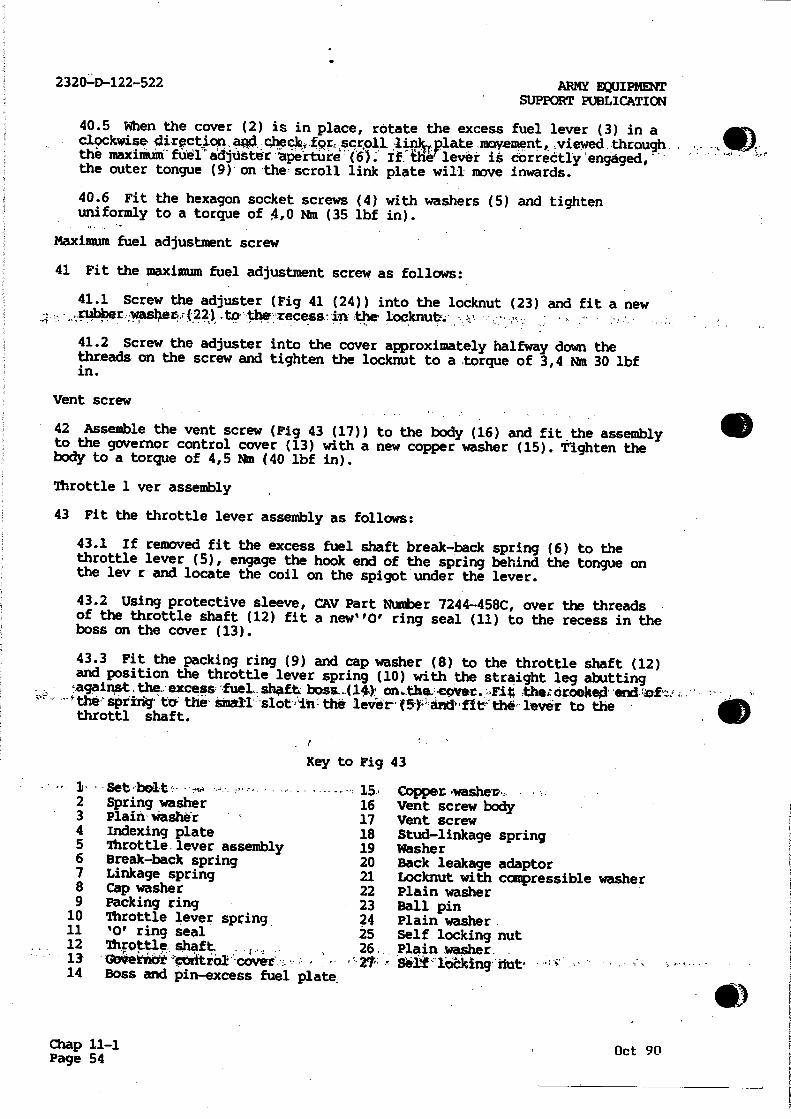
Key to Fig 43
- 11, Setloolt,, Copper washet, 2 Spring washer 16 Vent screw body 3 Plain washer 17 Vent screw 4 Indexing plate 18 Stud-linkage spring 5 Throttle lever assembly 19 Washer 6 Break-back spring 20 Back leakage adaptor 7 Linkage spring 21 Locknut with compressible washer 8 Cap washer 22 Plain washer 9 Packing ring 23 Ball pin 10 Throttle lever spring 24 Plain washer.11 '0' ring seal 25 Self locking nut 12 13
Throttle shaft • ,
Obverniat'co dtrOl -cover26.
• . Plainlesher SerUlikkingriut. "
14 Boss and pin-excess fuel plate
Chap11-1 Page 54
Oct 90

•
ARMY EQUIPMENT SUPPORT PUBLICATION
2320-D-122-522
Fig 43 Throttle lever assembly, vent screw and pressurising valve
43.4 Pull the throttle shaft fully upwards and locate the indexing plate (4) on the shaft with the 'X' stamped on the plate uppermost. Secure the throttle lever assembly to the shaft with plain washer (26) and self locking nut (27), temporarily tighten to a torque 4,5 Nm (40 lbf in).
43.5 Fit the setbolt (1) with spring and plaih washers (2) and (3) through the slot in the indexing plate (4) to the boss on the throttle lever (5). Screw in only two turns at this stage.
Oct 90 Chap 11-1_ -t5Page

2320-D-122-522 menrEummtam SUPPORT PUBLICATION
43.6 Fit the stud (18) in the transverse slot in the lever (5) and retain ,with., usher;(24) and self . locking ,42.N. do pat_ tighten .at this stage. Pit the Shorter hoOk'Of the 4inlikle'spifn§r (7) to the, stud with its open end towards the throttle shaft. •
43.7 To achieve sufficient lift on the lever (5) to clear the previously assembled idling lever, slacken the locknut (27) half a turn and pull back the.throttle lever (51 against the compression of the spring. Retaip in this position using a suitable llmm socket fitted to the vent screw body (16). The socket should not be removed until after the throttle control bracket has been fitted.
43.8 Re-tighten the self locking nut (27) to a torque of 4.5 Nm (40 lbf in).,Sc5ew-in.the setbolt .(1), amd.tighten a•a- 5,6 Nak (50. lbf
43.9 Assemble the ball pin (23) and washer (22) to the long slot in the 'fever and secure with locknut and integral 'Belleville' washer (21).
Back leakage adaptor
44 To fit the back leakage adaptor (20), pull the idling lever clear-and.fit th adaptor with a new washer (19) to the cover (13). Tighten to a torque of 20 Nm (180 lbf in).
Delivery valve assemblies
45 To fit the delivery valves proceed as follows:
Note ...
The following procedure is the same for each of the delivery valves.
45.1 Fit a new washer (Fig 44 (17)) to the banjo connection (18), insert the delivery valve assembly (16) with the larger diameter end first, followed by the washer (15).
45.2 Place the shank of the spring peg (13) in the spring (14) and insert both, spring peg end first, into the delivery valve holder (12).
45.3 Strewthe,assestpledtvaIveJhadeeintOTthetehjerengaging the end of the spring on the spigot of the delivery valve (16). Holding the banjo connection (18) in, the soft jaws of a vice, tighten the delivery valve holder to a torque of 41,0 Nm (360 lbf in).
45.4 Fit the assembled valves to the hydraulic head (11), in the positions hated durin% dismantling,..with, the banjo bolts (1Wandinewpwashers (20) positioned either side of the banjo, tighten finger tight only.
45.5 Fit the support bracket (10) to the delivery valve holders and secure, finger tight, with nuts (9).
45.6 Tighten the banjo bolts to a torque of 35,6 Nm (320 lbf in), and the support bracket nuts to a torque of 41,0 Nat (360 lbf in).
Chap 11-1 i Page 56
Oct 90

ARMY EQUIPMENT "SUPPORT PUBLICATION
2320-D-122-522
20 19 18 17 16 15 LR4i 671A
1 Anti-stall screw 9 Nut-support bracket 20 Washers Washer and locknut 10 Support bracket 21 '0' ring seal
2 Throttle control 11 Hydraulic head 22 Plug screw bracket 12 Delivery valve holder 23 'Torx' screw
3 Max speed screw 13 Spring peg 24 Shakeproof washer and locknut 14 Spring 25 Timing cover plate
4 Solenoid 15 Washer 26 '0' ring seal 5 '0' ring seal 16 Delivery valve 27 Washer 6 Spring 17 Washer 28 Spring washer 7 Plunger 18 Banjo connection 29 Set bolt 8 Banjo assembly 19 Banjo bolt
Fig 44 Throttle control bracket, solenoid and timing cover plate
Solenoid assembly
46 Using protection cap OAT Part Number 7044-897 fit a new '0' ring seal (5) to the solenoid (4). Insert spring (6) in the plunger (7) and fit to the solenoid. Fit the solenoid assembly to the hydraulic head (11) and using a suitable socket spanner tighten to a torque of 15,0 Nm (130 lbf in).
Oct 90 Chap 11-1 ,Page 57

2320,46-122-522 ARMY EQUIPMENT SUPPORT PUBLICATION
Timing cover plate
47 ' Position_ a new 10'," ring- seal; (26r isa the, reCO21 co' the wisp !housing•, fit: • - the •timing cover plate (25) and secure with. 'Torxf screws (23) and shakeproof washers (24). Tighten the screws to a torque of 2,3 Nm (20 lbf in). Using protection sleeve CAV Part Number 1804-429, fit '0' ring seal (21) to plug screw (22) and screw the plug in the cover. Tighten the plug screw to a torque of 4,5 Nm (40 lbf in).
Throttle control bracket
48 To fit, the throttle. control bracket proceed as follows:
48.1 Fit the anti-stall screw, washer and locknut (1) to the throttle eontrOtbracket, y aricr speea Ar„a•:=
48-2 Pull the throttle lever clear and assemble the control bracket to the governor cover with the two-set bolts (29) plain-and spring washers (27) and (28). Tighten the bolts to a torque of 7,9 Nm (75 lbf in).
48.3.. Remove.,the llram. socket .from-the-..vent.. screw 11090Y;.,•
Excess fuel linkage
49 Using a suitable hook tool, engage the longer hook of the linkage spring (Fig 45 (3)) with the lower annulus of the pin (2) on the excess fuel plate. Abut the long leg of the break-back spring (4) to the upper annulus of the pin (2) on the opposite side to the linkage pin.
50 To prevent the break-back spring becoming disengaged from the excess fuel pin when the throttle lever is operated, the stud (6) should be pushed forward in its slot towards the idling shaft and the locknut tightened to a torque of 4,5 Nm (40 lbf in).
1 Excess fuel shaft 5 Throttle lever 2 Pin-excess fuel plate 6 Stud-linkage spring 3 Linkage spring 7 Locknut-linkage spring 4 Break-back spring
Fig 45 Location of linkage spring.
Chap 11-1 Page 58
Oct 90

ARMY EQUIPMENT 2320-D-122-522
SUPPORT PUBLICATION
TEST PLAN
General
51 For general conditions of testing and test rig requirements refer to
AESP-2910-F-101-302. For testing the DPS fuel injection pump on Calibration
fluid 'C' refer to AESP 2320-D-122-533 Section 2, Schedule 2.
Note .-..
The following test plan must only be used for testing the DPS fuel
injection pump fitted to Land Rover 2,5 litre non-turbo diesel engines.
Test conditions
52 The following conditions must be conformed to when carrying out the test:
52.1 Test oil: ISO 4113 at a temperature of 40 + or - 2°C.
52.2 Inlet feed pressure: 0,1 bar.
52.3 Nozzles: ISO 4010.
52.4 Nozzle opening pressure: 125 + 3 - 0 bar.
52.5 High pressure outlet connections: Original.
52.6 High pressure pipes: 6 x 2 x 600 mm (ISO 4093.1).
52.7 Test bench drive: HF 533 in unsupported position.
Setting excess fuel mechanism
53 Should the excess fuel mechanism require re-setting, the following
procedure must be used:
53.1 Screw the anti-stall screw head out to 70 mm from the front mounting
face of the pump housing.
53.2 Insert a 0,5 mm spacer between the anti-stall screw and the throttle
lever.
53.3 Excess fuel linkage - push the excess fuel spindle round fully
clockwise. Slide the excess fuel stud forward to take up all the slack in
the linkage spring (DO NOT TENSION THE SPRING).
53.4 Remove 0,5 mm spacer.
ISO test procedure
Preparation
54 Before carrying out the test procedure the following observations and
settings must be made.
54.1 All delivery readings (other than critical deliveries) to be taken
over 500 shots, except test (7) using 100 shots, test (10) using 2000 shots
and test (19) using 300 shots.
54.2 All special tools and adaptors required for testing the pump are
listed in AESP 2910-F-101-302.
Oct 90 Chap 11-1 .Page_59

-,'- 2320.40,422522 ARMY' EQUIPMENT ' SUPPORT PUBLICATION
54.3 Where marked thus* use 30 seconds glass draining time and allow test oil to settle for 15 seconds before taking readings unless stated otherwis by the test bench- menufackurpwinstmucticx*c- 7 =
54.4 Pump to be free from leaks both when stationary and running.
54.5 A 2,00 mm shim is fitted to additional shimming is required.
54.6 Remove solenoid and connect location, using adaptor.
54.7 Fully back off the maximum speed screw. Throttle to be fully open.'
5.44, Setmaxinami:fueLadjUdtii*Scretttci:prottadeAfi abOa-ML:the:1;u-race of the locknut.
5.4:9. Screw transfer pressure adjuster fully. out and'then 1 1/2 turns in before commencing test.
54.10 Set latch valve adjuster until one•thread.is,showin%abovepe, surface of the lOcknut.
54.11 Slacken throttle shaft locknut one, half of a turn only.
54.12 Loosen the vernier plate screw, turn vernier plate fully anti-clockwise, and retighten screw and nut.
54.13 Fully back off idling screw.
54.14 Fit auto-advance gauge and set to zero.
Test
55 To test the pump carry out the tests listed in Table 1.
• Note. • ••.,• , . ,- • _
the piston spring cap on assembly. No
transfer pressure gauge to the solenoid
TABLE 2 FUEL PUMP TESTING
Critical fuel deliveries are given in mm3,/stroke. Hence the tester must determine the number of,strokes applicable, in accordance with the test machine manufacturers instructions.
'Test-. (.1)
Operation., (2)
rev/Win (3)
Requirements (4)
1 Priming. 200 Obtain delivery from all injectors, and back leak.
2 Stabilisation 2100 Run pump for 3 minutes to stabilise.
3 Transfer pressure 100 0,55 bar (8 Lbf in)-minimums
4 Advance, check—% t, -,• 100, 0° to 1 2°-•.(.(kt•Q,:(44;mm),,i,,I,,:. • •,
`Chap 11-1 Page 60
(continued)
Oct 90

-ARMY EQUIPMENT SUPPORT PUBLICATION
2320-D-122-522
TABLE 2 FUEL PUMP TESTING (continued)
Test (1)
Operation (2)
rev/Win (3)
Requirements (4)
5
6
7
8
9
Advance setting
Transfer pressure
Back leakage
Advance check
Maximum delivery setting: See Note. Para 55
1300
1300
1500
2000
*2000
Move throttle lever to anti-stall stop.
10 Vernier plate setting
600
Adjust transfer prepure scr w to
obtain advance of 4 (3,2 mm).
3,8 to 4,8 bar (56 to 70 lbf in2 ).
15 to 40 cm3 per 100 strokes tide
cycle. (Flow rate 225 to 600 cm min).
7° to 7 1/2° (5,6 to 6,0 mm).
39,0 + or - 0,4 mm3 stroke. Spread3
between lines not to exceed 4,0 mm
stroke.
Using 2000 strokes (achieved through
4 x 500 strokes), slacken throttle
shaft locknut by one half turn max.
Loosen vernier plate screw and turn
vernier plate clockwise untilla delivery of 4 1/2 to 5 1/2 cm' is
achieved. Retighten both locknut and
screw before taking reading.
Move throttle lever to fully open position.
11 Delivery check 2000 Record average delivery in cm3.
12 Governor setting 2300 Set throttle by maximum speed adjustment screw to give average
delivery of between 7,5 and 8,0 cm3.
Lock stop screw.
13 Fuel delivery check
2460 Averagl delivery to be not more than
3,0 cm'.
14 Delivery check 2000 With throttle set as at (12), average delivery not to be less than
at (11), minus 0,5 cm".
Run machine down to 200 rev/bin and stop.
15 Throttle ball setting
D Set throttle ball at furthest extremity of slot, to give 26 to 44 mm of movement between anti-stall
stop and maximum speed stop.
Remove transfer pressure gauge, fit and energise solenoid, restart machine
and vent as in (1).
16 Fuel delivery check
2000 Delivecy to be as at (14) + or.- 1,0 cm".
(continued)
Oct 90 Chap 11-1 Page 61

2320-0-422-522
TABLE 2 FUEL PUMP TESTING (continued)
ARMY EQUIPMENT SUPPORT PUBLICATIa4
Test (1)
Operatiori (2)
rev/min (3)
Requlrements (4)
Stop machine, remove advance pressure end plug, fit any advance test.clug from 7244-435 series,and connect-to pressure gauge using a suitable fuel connection.
Move throttle to anti-stall stop, start machine and run to 600 rev/min before continuing test.
delitrery • 335. '
18 Latch out valve setting
180
19 Excess fuel check 110
20 Latch out check 210
21 Solenoid shut-off 200
Remove test plug
22 Timing
and refit pressure
0
.setitile:scieurtccgive.an..aviiagesi delivery of between 5,0 and 5,5 cm'
Screw latch valve adjuster fully in pressure gauge should read zero, then screw out until pressure gauge pointer starts to rise.
Average delivery to be 13,5 cm3minimum for 300 stroke time cycle. Check that the pressure gauge point r has returned to zero.
Ensure pressure gauge pointer has risen.
De-energise solenoid and wait for 5 seconds before operating the trip gear. Average delivery not to exceed 1,25 cm'.
end plug.
Use outlet "V' (55 atm pressure). Offset value to + 45.'. on graduated Scale
Refitting
56 To fit the DPS fuel injection pump proceed as follows:
56.1 Fit the pump with a new joint gasket to the rear cover, secure with the three nuts (Fig.46 (10)) and the single nut and bolt (7) to the support bracket (8), tighten finger tight only.
56.2 Remove the centre part of the special tool, fit the pulley retaining nut and tighten to a torque of 42 to 48Nm (31 to 35 lbf ft).
56.3 Check that the crankshaft has not moved. Remove the plug from the timing plate (Fig 47 (1)) on the side of the pump and insert the timing tool (2) (Table I Serial• No 2). If necetsary rotate, the pump to ensure that the bottom groove on the centre pin of the tool is flush with the end of the tool ag,i11-.11SArated:
'Chap 11-1 Page _62 Oct 90

•
ARMY SQUIPMEN't SUPPORT PUBLICATION ' 2320-D-122-522
1 Fuel feed pipes 6 Oil filter adaptor 2 Delivery valves 7 Nut and bolt 3 Fuel inlet pipe 8 Support bracket 4 Spill return pipe 9 Ball pin-throttle lever 5 Solenoid electrical connection 10 Securing nuts
Fig 46 Refitting DPS pump 56.4 Evenly tighten the three nuts securing the pump to the cover and the single nut and bolt to the support bracket to a torque of 22 to 28 NM (16 to 22 lbf ft).
56.5 If necessary align the timing pointer (3) with the scribed line (4) on the pump flange. If a new pump is being fitted and there is no line scribe one to coincide with the pointer.
56.6 Remove the timing tool from the pump and refit the plug. 56.7 Remove the outer part of the special tool and refit the two front cover securing bolts and the inspection cover complete with hose clip, tighten the cover securing bolts to a torque of 22 to 28Nm (16 to 20.6 lbf ft).
56.8 Remove the flywheel timing pin (Table 1 Serial No 3) from the flywheel housing and refit the plug.
56.9 Refit the oil filter adaptor assembly (Fig 46 (6)) using a new joint gasket.
56.10 Connect the throttle link, to the ball pin (9) refit the fuel feed pipes (1), the fuel inlet pipe (3), spill return pipe (4) and the electrical connection to the solenoid (5).
Oct 90 Chap 11-1 Page 63

2320-rD.122-522- ARMY EQUIPMENT SUPPORT PUBLICATION
LR4186M
1 Timing plate 2 Timing tool
3 Timing pointer 4 Scribed line
Fig 47 Timing tool inserted in DPS pump
56.11 Reconnect the vehicle batXery leads and.mhere applicable the radio battery leads.
FUEL INJECTORS
Special tools. ,
57 Special tools for fuel injector overhaul and testing are included in ETS 06002.
Checking nozzle assemblies
WARNING ...
DO NOT ALLOW THE FUEL SPRAY TO CONTACT THE PERSON OTHERWISE INJURY MAY RESULT, Fpwstsibi PENETRATDON,
- Chap 11-1 Page 64 I
Oct 90

ARMY EQUIPMENT . SUPPORT PUBLICATION
Fig 48 Fuel injector spray check on engine
General
2320-D-122-522
LR4171M
58 When an injection nozzle is considered to be the cause of irregular
running and loss of power, a quick check may be made by loosening the fu 1
feed pipe union nut on each nozzle in turn, whilst the engine is idling at
approximately 1000 rev/Min. If the injection nozzle assembly being checked has
been operating properly, there will be a distinct reduction in engin speed
accompanied by obvious roughness, but a faulty injection nozzle may make
little or no difference to the engine note when its fuel feed pipe is
loosened.
Spray check
59 To check the spray on a suspect nozzle assembly carry out the following:
59.1 Remove the fuel spill rail pipes from the nozzles.
59.2 Disconnect the fuel feed pipe (injection pump to nozzle) from the
nozzle to be checked and from the injection pump.
59.3 Release the fixing and withdraw the suspected injection nozzle
assembly, reconnect the pipe and nozzle assembly to the injection pump in a
position whereby fuel spray may be observed.
59.4 Loosen the union nuts securing the remaining fuel pipes to injection
nozzles.
59.5 Whilst turning the engine over with the starter, observe the manner
in which fuel issues from the nozzle and compare the spray form with the
correct form as illustrated (Fig 48).
Oct 90 Chap 1.1-1
Page 65

2320-D-122-522 ARMY EQUIPMENT SUPPORT PUBLICATION
1 Fuel feed pipes 5 Washers 2 Injectors 6 CyNnder head 3 Spill return pipe 7 Copper washer 4 Securing nuts 8 Steel washer
Fig 49 Removal of injectors from cylinder head
59.6 Very little fuel should issue from the main spray hole with the engine turning over at starter Speed but a fine spray comparable to that illustrated(Fig418))shoulcheject,from-fimiroxil!alY-Vrarbole• '
59.7 If the fuel is more in the form of a liquid jet or issues from the main pintle hole, then the nozzle and holder assembly should be removed for overhaul and a replacement unit fitted.
59.8 Refit the injector and tighten the securing nuts to a torque of 6 to 8 Nm (4.5 to 6 lbf ft). Refit the spill rail pipes with new washers fitted either side of the banjos and tighten the banjo bolts to a torque of 14 to 20 NM (10.3 to 15 lbf ft).
Removal
60 The fuel injectors should be removed from the engine as a set attached to the spill rail.
60.1 Disconnect the fuel feed pipes (Fig 49 (1)) from the injectors (2) and the spill return pipe (3) from the injectors to the top of the fuel filter.
•
71911 (346) Vehs 8 Wpns Br REME Chap 11-1 Page 66
. 950' MM-0804 " Dec.94 (Amdt 5)
•,„
- ••
•

•
•
•
ARMY EQUIPMENT SUPPORT PUBLICATION
1 End cap 5 Valve spindle 2 Sealing washer 6 Cap nut 3 Adjusting screw 7 Nozzle valve 4 Pressure spring 8 Nozzle body
2320-D-122-522
LR4173M
Fig 50 Exploded view of fuel injector
60.2 Remove the nuts (4) and washers (5) securing the injectors to the cylinder head (6) and withdraw the injectors from the engine.
60.3 Remove and discard the steel sealing washers (8) and the copper washers (7) from each of the injector locations.
Dismantling
61 To dismantle the injectors proceed as follows keeping the components from each assembly separate:
61.1 Disconnect the injectors from the spill rail.
61.2 Remove the combined locknut and end cap (Fig 50 (1)) and withdraw the sealing washer
(2).
61.3 Unscrew the pressure adjusting screw (3), withdraw the pressure spring (4) and the valve spindle (5).
61.4 Unscrew the cap nut (6) and withdraw the nozzle valve (7) and body (8).
9501\JP-0804 - Dec 94 (Arndt 5)
Chap 11-1 Page 67

. ARMY EQUIPMENT SUPPORT,PUBLICATION
Cleaning and examination
62' 'Soak the CoMpodent parts Of'each aisenky -Art e I Ca ibration Fluid to loos n carbon deposits, but do not allow parts to become interchanged between assembli s. After soaking carry out the following:
62.1 Brush away all external carbon deposits using a brass wire brush and return the components to the fluid bath.
B
C
Q Zm
E .
• ••••• • 4 4-4.• • r •
Fig 51 Cleaning fuel passages.
Chap 11-1 Page 68
D LR4174M
Oct 90
•
4Ib

ARMY EQUIPMENT 'SUPPORT PUBLICATION
2320-D-122-522
LR4175M
Fig 52 Cleaning nozzle
62.2 Particular care must be exercised when cleaning the pintle and seat of the nozzle valve to avoid scratching or scoring, which will result in spray distortion.
62.3 Clean the three fuel feed passages in the nozzle body (Fig 51 (A)) with a wire or drill of 1,5 mm (0.062 in) diameter.
62.4 Remove carbon deposits from the annular recess (B) in the nozzle body using the tool illustrated, or suitable alternative.
62.5 Remove carbon from the valve seat (C), using the appropriate tool with a rotary motion.
62.6 Using the correct size probe from the cleaning kit fitted to the pintle hole cleaner (D), insert the probe into the bore of the nozzle valve body and allow the end to extend through the main fuel outlet (E), rotate to remove carbon.
62.7 Carbon can be removed from the nozzle valve cone by inserting the valve into the tool illustrated (Fig 52) and rotating in alternate directions whilst pressing the valve inward.
62.8 If the nozzle is blued or the seating has a dull circumferential ring indicating pitting or wear the nozzle body and valve should be returned to the manufacturers and replacement parts fitted. Do not attempt to lap the nozzle valve to the body.
Oct 90 Chap 11-1 Page '69

23204)422-522 ARMY EQUIPMENT • SUPPORT PUBLICATION-
62.9 Clean the auxiliary spray hole using the special tool fitted with probing:.wire.0420.mm (L0084n), iiiameter- on4,1,5sm,(0-002.4)) to extend from the'chuck to "minimise the' possibili y "of the wire breaking while probing.
62.10 EXamine the pressure faces of the nozzle body and nozzle holder for scoring or scratches. These faces must be perfectly smooth.
62.11 Secure the flushing tool Part number 180109E to the testing outfit Part Number DX.710, fit the nozzle body, spray holes uppermost, to the flushing tool and vigorously pump test oil through the nozzle body to remove any particles of carbon remaining after probing and scraping.
Fig 53 Flushing_ tool
Reassembly
63 To reassemble the injectors carry out the following:
63.1 Fit the nozzle valve to the nozzle and check for freedom of movement.
63.2 Immerse the nozzle body and valve in the fluid bath and assemble whilst submerged.
.63.43-Afashi,the:reMaihing,:ebikpbDentaanrUteassemblefistreversakorde4.of removal. '
Chap 11-1 Page 70
Oct 90

.ARMY EQUIPMENT 2320-D-122-522
SUPPORT PUBLICATION
Testing
General
64 To check a nozzle assembly and to ensure that it is functioning correctly,
an Injector Tester Part Number DX.710 or suitable alternative is essential. A
bench covered with linoleum or non-ferrous sheet metal is most suitable for
mounting the tester, such a surface facilitates cleanliness which is ess ntial
when checking. in Betweemthe bench- and-tester,"a tray, also of
non-ferrous metal, should be positioned to prevent spilt fuel spreading.
65 The efficient operation of the injection nozzle assembly is dependent on
four main conditions, as follows:
65.1 The nozzle valve must be open at 135 Atmospheres.
65.2 The rate of back leakage must be within 100 to 150 Atmospheres.
65.3 Seat tightness must be sufficient to prevent leakage.
65.4 Spray form must compare favourably with that shown in Fig 56.
66 Pressure setting, back leakage and seat tightness tests are made by
coupling the injector direct to the pressure feed pipe on the test equipment,
but a special adaptor must be fitted between the pipe and the injector
assembly when testing for spray form. This adaptor increases the pressure of
fuel to the injector sufficiently for the main and auxiliary spray form to be
determined.
Test procedure
WARNING ...
THE INJECTION NOZZLE MUST NOT BE ALLOWED TO POINT =WARDS THE OPERATOR WHEN
SPRAYING AND THE HANDS MUST NEVER BE ALLOWED TO COME INTO CONTACT WITH THE
SPRAY WHICH HAS A FORCE THAT CAN PENETRATE THE FLESH
67 To test the injector carry out the following:
67.1 Remove the cap from the fluid container on the test unit and fill
with 0,8 litre (1.5 pints) of 'Shell Calibration Fluid'.
67.2 Air vent the system by removing the vent screw, allow fluid to plow
freely for a few seconds and replace the screw whilst the flow continues.
•
67.3 Operate the pump handle on the test unit until fluid flows from the
pipe.
67.4 Connect the injector assembly to the pressure feed pipe with the
nozzle pointing downwards. The length and bore of this pipe is important
and replacement pipes must be approximately 75 mm (2.8 in) between the
union nuts and of 3 mm (0.118 in) bore.
67.5 Close the check valve to keep the pressure.gauge out of circuit and
operate the hand lever several times to expel all air from the system.
67.6 Back leakage test --To carry out this test proceed as follows:
67.6.1 Adjust the injector to open at 160 to 170 atmospheres, raise the
pressure as indicated on the gauge to just below this figure, rel ase
the handle and time the pressure drop from 150 atmospheres down to 100
atmospheres.
Oct 90 Chap 11-1
Page 71

2324,4422-,522 ARMY EQUIPMENT'"
SUPPORT' PUBLICATION
1.!
LeAtirni Fig 54 Leak back test
67.6.2 This should be not less than 5 seconds for the original nozzle and not less than 7 seconds if a new nozzle is fittea, and pot mop than 36 seconds for either with the oil temperature at 10- to 21'C (50' to 70°F)..
67.6.3 Check externally the top and bottom of the nozzle cap nut and pressure pipe union nuts for signs of fluid leakage. If leakage occurs at the nozzle cap nut, remove the nut and examine the pressure faces of the nozzle holder and nozzle. body for presence of foreign matter or surface scoring.
• - . , . 67;6:ti: riot 14::essetablY --ShOWingY nixsigner olleakage-- but -having' an • excessive rate of pressure drop indicates a worn nozzle valve,. if this .
• condition is evident the nozzle valve and body should be renewed.
• • •.•• 0
Chap 11-1 Page 72
Oct 90

ARMY EQUIPMENT .SUPPORT" ̀PUBLICATION
2320-D-122-522
Fig 55 Spray check rig
Fig 56 Spray form
Oct 90
3
1
L.
6
LR4179/A
Chap 11-1 Page:73

V.,
2320-0-122-522 ARMY EQUIPMENT SUPPORT PUBLICATION
67.7-; Pressuna,settin9:'4 Adjust thetoper'atibnaLciriditindlbrissureof the nozzle velVe'to'135 atmospheres. ,
67.8 Seat tightness - Wipe the bottom face of the injection nozzle dry and raise the pressure in the system to 125 atmospheres. A slight dampness on the bottom face is permissible, blob formation or dripping indicates a badly seating valve in which case the assembly should be dismantled for further examination.
67.9 Bp_ray form - Fluid delivery to the injector assembly when testing the spray form must be characteristically similar to fuel delivery under normal operating conditions. To effect these conditions an adaptor CAV Part Number Y7044872 must be fitted between the injector and the pressure pipe— Fit ths•adaptorand carnrout the spray Pan check as follOWst ,.:•
67.9.1 Connect the adaptor assembly to the pressure pipe.
67.9.2 Remove the end cap of the adaptor and adjust the opening pressure of the valve to 220 atmospheres.
67.9.3 Fit the injector to be tested to the adaptor.
67.9.4 With the check valve closed, operate the handle to expel air from the system. The auxiliary spray form should be tested at 60 strokes per minute and the main spray at 140 strokes per minute. Spray development from starting to running speeds are shown in Fig' 56, refer to the illustration to compare with the spray form of the injectors under test.
67.9.5 Spray formation should be well formed and free from splits or distortion. A slight centre 'core' can be disregarded. Observe the main spray through 360° to ensure a uniform spray. When satisfactory, fit the combined locknut and end cap.
Refitting
68 To refit the injector assemblies to the engine proceed as follows:
68.1 Fit new steel sealing washers (Fig 49 (8)) to each of the injector locations in the cylinder head. To ensure that the washers are correctly fitted, use a length of thin welding wire to guide one washer only into each port with the domed side toward the injector.•,
68.2 Refit the injectors to the spill rail with new washers fitted each side of the banjos, tighten the banjo bolts to a torque of 14 to 20 Nm (10, 3 to 15 lbf ft), fit a new copper washer (7) to each injector and fit the assembled injectors.and spill rail. to the cylinder head,
68.3 Secure the injectors to the studs with the nuts (4) and washers (5) and tighten the nuts to a torque of 6 to 8 Nm (4.5 to 6 lbf ft).
68.4 Connect the fuel feed•pipes (1) and spill return (3) taking care not to over tighten the union nuts.
FUEL LIFT PUMP
Removal
69 Remove the fuel lift pump from the engine complete with the side cover• to which it is mounted.
71911 (346) Vehs & Wpns Br REME Chap 11-1 Page 74
9501' JP-0804 Dec 94 (Amdt 5)
69

ARMY EQUIPMENT 2320-D-122-522
SUPPORT PUBLICATION
Dismantling
70 To dismantle the fuel lift pump carry out the following:
70.1 Remove the pump from the side cover and remove and discard the joint
gasket.
70.2 Mark the upper and lower halves of the pump casing tqensure correct
alignment on reassembly. '
70.3 Remove the fixing screws (Fig 57 (1)) from the upper casing (2), and
while pressing the diaphragm tab (3) against the pump lower casing (4),
lift the upper casing clear.
70.4 If it is necessary to remove the valves (Fig 58 (1)) from the upper
casing (2), note which way round they are fitted, and cut away the
retaining stakes with a scraper. Warm the upper casing, and withdraw the
valves.
• Oct 90
1 Fixing screws 2 Upper casing
LR4180M
3 Diaphragm tab 4 Lower casing
Fig 57 Removing fuel lift pump upper casing
Chap 11-1 'age 75

"2320-0422,-522 ARMY EQUIPMENT SUPPORT PUBLICATION
70.5 Whilst pressing down the metal part of the diaphragm assembly (Fig 59 (1)) turn through 90' in either direction and withdraw the diaphragm assembly'andk-springe1,24.. -
70.6 Unstake the oil seal housing (3) and lever out the oil seal and retainer.
70.7 Remove the staking from the rocker arm retainers (Fig, 60 (1)). withdraw the retainers, rocker arm (2) and spring (3).
70.8 Withdraw the pin (4) and washers (5) to detach the operating link (6).
70.9 It is unlikely that the hand priming mechanism will ever require replacement, it can be removed by filing the hexagon. each side of theopetating.levecean&spkingia0Ltheqevev
1 Valves 2 Lippe! casing
Fig 58 Removing valves from upper casing
U141111U
•
Chapin-1 Page 76
Oct 90

ARMY EQUIPMENT SUPPORT PUBLICATION
—2320 -D-122 -522
1 Diaphragm assembly 2 Spring
Oct 90
3 Oil seal housing
Fig 59 Diaphragm assembly removal
LR4183M
1 Rocker arm retainers 4 Pin 2 Rocker arm 5 Washers 3 Spring 6 Operating link
Fig 60 Removing rocker arm
Chap -l171 Page .77,4

2320-D-122-522 ARMY. EQUIPMENT SUPPORT PUBLICATION
Cleaning
71 Thoroughly clean all the components in 4fapt erasene...
Examination
72 Examine the fuel lift pump components as follows:
72.1 Check the diaphragm assembly for signs of hardness, cracking or porosity.
72.2 Examine the rocker arm contact face, pivot pin, operating link and diaphragm pull rod slots for wear, evidence of slight wear is acceptable.
72.3 Sprtngs'gaskets.:-and_seals:shoukkte.refiewed..4'.
Reassembly
73 Reassemble the fuel lift pump as follows:
73.1 Assemble the.operating,link 4Fig,60-(6)) to,the,rockerann (2) and retain with the pin.(4r and washers'(5).. Fit the.spring (3) to the -rocker .arm.
73.2 Fit the rocker assembly to the lower casing, fit the retainers (1) and secure by staking.
73.3 Fit_the oil seal and its retainer to the lower casing and secure by staking.
73.4 Position the diaphragm return spring (Fig 59 (2)) in its location on the lower casing, place the diaphragm assembly (1) over the spring with the flattened end of the pull rod aligned with the slot in the operating lever. Push the metal portion of the diaphragm inwards, when the pull rod engages with the operating lever turn the diaphragm through 90 to lock.
73.5 If the valves have been removed from the upper casing, fit new ones ensuring that they are fitted the same way round as noted during dismantling. Stake the valves to retain them in position. .
, • • ,".•731,6 •PlaCettliCupPercasihirbelf;:iii,,prisititstaldigVitiothe:Slarkiloade.'-"' before dismantling. Fit the securing screws, but do not tighten; using the hand priming lever fully depress the diaphragm and tighten the screws. The diaphragm outer edges should'be.approximately,flush with. the outer edge of . the pump joint faces when fitted.
Testing
74 To test the fuel lift pump proceed as follows:
74.1 Immerse the pump in a bath of clean kerosene and operate the hand priming lever several times to flush the pump.
74.2 Hold the pump clear of the bath and continue to operate the hand primer until the pump is empty, then place a finger over the inlet port and operate the hand primer several times. A distinct suction should be heard when the finger is removed from the inlet port, denoting a reasonable-degree of suction, has been developed.
Chap 11-1 1 Oct 90 Page 78

ARMY EQUIPMENT 2320-D-122-522
SUPPORT PUBLICATION
74.3 Place a finger over the outlet port and again operate the hand
primer. Air pressure should be felt for two or three seconds after movement
of the priming mechanism has ceased.
74.4 Build up the air pressure in the pump again, and with a finger held
firmly over the outlet port, submerge the pump completely in the kerosene
bath, and check the joint face edges for signs of air leakage.
Refitting
75 Refitting the fuel lift pump is the reverse of the removal procedure,
using new joint gaskets between the pump and side cover and the side cover and
engine. Tighten -the fuel lift pump securing nuts to a torque of 20 to 28 Nm
(14.7 to 20.6 lbf ft) and the side cover securing bolts to a torque of 23 to
30 Nm (17 to 22 lbf ft).
•
FUEL TANKS
WARNINGS ...
(1) DANGER OF =FIRE ALWAYS EXISTS MEN WORKING ON OR REMOVING FUEL TANKS FROM
VEHICLES.-WORK MUST BE CARRIED OUT IN A. WELL VENTILATED, AREA.
(2) FIRE EXTINGUISHING EQUIPMENT MUST BE AVAILABLE AT ALL TIMES AND THE VEHICLE BATTERIES AND WHERE APPLICABLE THE RADIO BATTERIES MUST BE
COMPLETELY DISCOCVECTED.
(3) NOTICES SUCH AS "NO SMOKING", "HIGHLY FLAMMABLE VAPOUR", "RESTRICTED
AREA" ETC. MUST BE DISPLAYED SO AS TO BE VISIBLE FROM ALL APPROACHES.
General
76 The position of the fuel tank differs between Land Rover 90 Diesel
vehicles and Land Rover 110 Diesel vehicles. On Land Rover 90 the fu 1 tank is
fitted on the right hand side of the vehicle, whereas on the Land Rover 110 the fuel tank is fitted at the rear of the vehicle and centrally mounted
between the chassis members.
Removal
Side mounted fuel tank
77 To remove the side mounted fuel tank proceed as follows:
77.1 Disconnect both positive and negative leads from the vehicle battery
and where applicable the radio batteries.
77.2 Drain the fuel tank into a clean container of suitable capacity.
77.3 Remove the right hand seat cushion and raise the locker lid.
77.4 Disconnect the electrical connections (Fig 61 (1)) from the fuel
level unit (2).
77.5 Detach the fuel feed pipe (3) from the outlet connection on top of
the tank.
77.6 Detach the spill return pipe (4) from the connection on top the tank.
77.7 Slacken the clips at the tank connections of the filler (5) and
breather (6) hoses and disconnect the hoses.
Oct 90 Chap 11-1 Page 79

.4,2320,0422-522
77.8 Detach the front (7) and rear (8) below the vehicle.
ARMY EQUIPMENT SUPPORT PUBLICATION
fixings and remove the tank from
'*
1 Electrical connection 5 Filler hose 2 Fuel level unit 6 Breather hose 3 Ebel feed' pipe ' 7' Front fixings 4 Spill return pipe 8 Rear fixings
Fig 61 Side mounted fuel tank removal
Rear mounted fuel tank
78 To remove the rear mounted fuel tank proceed as follows:
78.1 Disconnect both positive and negative leads from the vehicle battery and *we aPPAcat4e 4 11Er Wild*crkbAtte0-eal-t .kh A • ' `' n
78.2 Drain the fuel tank into a clean container of suitable capacity.
Chap 11-1 Page 80
Oct 90
•

' ARMY EduiPmEra SUPPORT PUBLICATION-
2320-0-122-522
- 78.3 Disconnect the fuel feed pipe (Fig 62 (1)) from the outlet in the
111, fuel level unit (2).
78.4 Disconnect the electrical connections (3) from the fuel level unit.
78.5 Slacken the clips at the tank connections of the filler (4) and
breather (5) hoses and disconnect the hoses.
78.6 Support the fuel tank, remove the front (6) and rear (7) fixings and
lower the tank to gain access to the spill return pipe (8).
78.7 Disconnect the spill return pipe and remove the fuel tank from below
the vehicle.
LR4185M
1 Fuel feed pipe 5 Breather hose
2 Fuel level unit 6 Front fixings
3 Electrical connections 7 Rear fixings
4 Filler hose 8 Spill return pipe
Fig 62 Rear mounted fuel tank removal
Oct 90 Chap .11-1
Page 81

.2320-D422-522 ARMY EQUIPMENT: - SUPPORT PUBLICATICEr
Refitting
Side. and.. rear fuel tanks:,
79 If a new tank is being fitted remove the fuel level unit, spill return elbow, fuel feed elbow (side tank only) and drain plug from the existing tank and fit them to the replacement tank, using new sealing washers and joint gaskets as applicable. Then fit the new tank in reverse order of the removal procedure.
FUEL LEVEL UNIT
Removal '
SideniauntiedrzfUe.ttank
80 To remove the fuel level unit from side mounted fuel tanks carry out the following:
80.1 Disconnect both leads frouLthevehicle battery and where applicable the radio batteries.
80.2 If the level of fuel in the tank is high, drain off sufficient fuel to prevent it from overflowing when the level unit is removed.
80.3 Remove the right hand seat cushion and lift the locker lid.
80.4 Disconnect the electrical connections from the level unit.
80.5 Using special tool (Table 1 Serial No 4) remove the fuel level unit from the tank. -
Rear mounted fuel tank
81 To remove the fuel level unit from rear mounted fuel tanks carry out the following:
81.1 Disconnect both leads from the vehicle battery and where applicable the radio batteries.
Drain.:offYitifficimittl.fnektodieingAiiiiaelrelAteilocAiteiliataleOi7tha fuel level unit aperture in the tank.
81.3 Disconnect the electrical connections and the fuel feed.pipe from the fuel level unit. '
81.4 Using.special tool (Table.l.Serial.No,4) remove.the fuel,level unit.
Refitting
82 To refit the fuel level unit on both side and rear mounted fuel tanks reverse the removal procedure.
FUEL SEDIMENTER
General
83 The fuel sedimenter is mounted on the right hand side of the chassis
on the left hind side of the Chassis; again adjacent to the fuel tank,' on vehicles -fitted with a rear- mounted fuel tank: • , •
Chap 11-1 Page 82
Oct 90

ARMY EQUIPMENT 2320=D-122522
SUPPORT PUBLICATION -
Removal/Refitting
84 The removal and refitting procedure for the sedimenters is self evident.
Cleaning
85 To clean the fuel sedimenters proceed as follows:
85.1 Disconnect the fuel inlet pipe from the sedimenter, raise pipe above
level of tank and support in this position to prevent fuel draining from
tank.
85.2 Support the sedimenter bowl, unscrew the bolt on top of the unit and
remove the-bowl.
85.3 Remove the element and clean all parts in kerosene.
85.4 Fit new seals, reassemble sedimenter and reconnect fuel inl t pipe.
• 85.5 Slacken off the drain plug, when diesel fuel free from air flows
tighten the plug.
FUEL FILTER
86 The method of removal/installation of the fuel filter is self evident,
when removing note should be made of the pipe connections to assist with
installation.
PRIME FUEL SYSTEM
87 If the sedimenter or fuel filter have been dismantled and air has entered
the system carry out the following:
87.1 Slacken the bleed pipe banjo bolt on top of the main fuel filter.
87.2 Operate the hand priming lever on the fuel lift pump until air free
fuel emerges.
Note • • •
Always ensure that the fuel pump lever is on the bottom of the operating
cam when priming, otherwise maximum movement of the lever cannot be
achieved.
87.3 Tighten the bleed pipe banjo bolt whilst fuel is still emerging.
88 If the DPS pump has been dismantled or renewed carry out the following:
88.1 Release the air vent screw (Fig 43 (17)) on the DPS pump governor control cover.
88.2 Operate the fuel lift pump hand priming lever until fuel free from
air emerges.
88.3 Whilst fuel is still flowing retighten the air vent screw.
88.4 Start the engine in.the normal way and check for leaks.
Oct 90 Chap11-1 Page '.83

--:=232070422-522 . ARMY EQUIPMENT. SUPPORT PUBLICATICt4
THROTTLE PEDAL ADJUSTMENT
89 If the throttle:cabie has been renewedrit wi1I be• necessary' to 'carry-out the following adjustments:'` '
89.1 Remove any slack in the cable by adjustment of the cable adjuster at the ngine end.
89.2 Depress the throttle pedal, by hand, to the full extent of the DPS pump linkage and adjust the pedal stop screw to take up all clearance between the screw and scuttle panel.
89.3 Recheck to ensure that no strain is placed upon the pump linkage.
• • -
-4.
Chap 11-1 Page 84
•
. Oct 90

-ARMY -EQUIPMENT 2320-D-122-522
- SUPPORT PUBLICATION
Chapter 11-2
3.5 L PETROL FUEL AND EXHAUST SYSTEM
CONTENTS
Frame Para
Oct 90
1 Introduction Carburetters
2 Removal ,3 Dismantling 4 Cleaning 5 Examination
Reassembly 6 Throttle butterfly.
7 Cold start assembly
8 Throttle lever assembly
9 Jet and float assembly
10 Piston and suction chamber
Tuning and adjustments
11 Special tools 12 General requirements prior to tuning
carburetters
13 Tamper-proofing 14 Carburetter balance
15 Mixture setting 16 Idle speed and linkage adjustment
17 Fast idle adjustment
Fuel tanks 18 General (WARNINGS)
Removal 19 Rear mounted fuel tank
20 Side mounted fuel tank Fuel level unit
21 Rear mounted fuel tank
22 Side mounted fuel tank
23 Fuel pump Refitting
24 Side and rear mounted fuel tanks
25 Fuel pump (CAUTION)
26 Fuel filter 27 Vapour separator 28 Solenoid valve 29 Non-return valve
Exhaust system 30 Removal (WARNINGS)
31 Refitting (WARNING)
Fig Page
1 Carburetter removal 3
2 Exploded view of carburetter 7
3 Cold start assembly 8
4 Throttle lever assembly 9
5 Jet and float assembly 10
Chap 11-2 Page 1

3211-13=122k; 5 22- - ARMY, EQUIPMENT-SUPPORT' PUBLICATION
Frame Fig Page
6 float-settings- - ,q 4t-t • ii. 7 , Fitting,the.jet. 11 8 Setting the jet 12 9 Piston and suction chamber 13 10 Manifold joints 14 11 Dashpot 14 12 Tuning the carburetters using Balancer 605330 16 13 Tuning the carburetters using Balancer B89 17 14 Mixture screw adjustments 18 15 Mixture jet level 19 16 Carburetter linkages 20 17 Rear:mounted.fuel, tank removal , -. 2A 18 Side mounted fuel tank removal 24 19 Fuel pump removal 27 20 Exhaust system 31/32
INTRODUCTION._ • ,
1 This chapter details the Unit, Field and Base repairs for the Fuel System fitted to Land Rover 110 and 127 vehicles with 3.5 litre V8 petrol engines.
CARBURETTERS
Removal
2 To remove.the carburetters proceed as follows:.
2.1 Disconnect the battery leads and where applicable the leads from the radio batteries.
2.2 Remove the elbows from the carburetter intakes and air cleaner (Fig 1 (1)).
.2.3 Remove the breather hoses and the clips ,(2) attaching the ,hbaelictitrAtieside'vati,..thet'crairbiltatte ,tictked.*:,,51.
2.4 Disconnect the throttle cable (7) from the left hand carburetter.
2.5 Disconnect the choke cable (4) from the left hand carburetter..
2.6 DiscoiuiecL the fuel spill return.pipe (5) from the right hand carburetter.
2.7 Disconnect the vacuum advance pipe to the distributor (4)
2.8 Disconnect the fuel supply pipe from the tank (3).Seal all pipe and hose ends to prevent the ingress of dirt or foreign matter.
.1Ascpruteote.-,the ,..int4rconneptinclAhit0'9".4 114 :9PA ,beWeen v,.. • the tc#0 . carhuretters:-
-Chap 11-2 Oct 90 Page 2
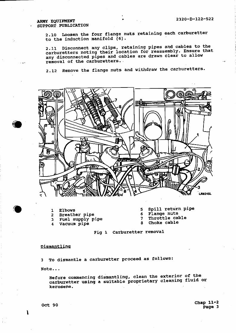
ARMY EQUIPMENT 2320-D-122-522
SUPPORT. PUBLICATION
2.10 Loosen the four flange nuts retaining each carburetter
to the induction manifold (6).
2.11 Disconnect any clips, retaining pipes and cables to the
carburetters noting their location for reassembly. Ensure that
any disconnected pipes and cables are drawn clear to allow
removal of the carburetters.
2.12 Remove the flange nuts and withdraw the carburetters.
1 Elbows 5 Spill return. pipe
2 Breather pipe 6 Flange nuts
3 Fuel supply pipe 7 Throttle cable
4 Vacuum pipe 8 Choke cable
Fig 1
Dismantling
Carburetter removal
3 To dismantle a carburetter proceed as follows:
Note...
Before commencing dismantling, clean the exterior of the
carburetter using a suitable proprietary cleaning fluid or
kerosene.
Oct 90 Chap 11-2
Page 3

ARMY EQUIPMENT.SUPPORT" PUBLICATION
3.1 Remove the two nuts and spring washers and withdraw the air intake adaptor and joint washer.
3.2 Unscrew, and. remove_the piston damper assembly., and drain the oil (Fig 2 (1)).
3.3 Remove the three screws (6) and lift-off the suction chamber (3) complete with piston. (5) and spring (4).
3.4 Remove the spring clip from the top of the piston rod and withdraw the piston and spring.
3.5 Unscrew the, fuel metering needle guide locking screw.(7) f. theneedle;Lcannotbez,removedlrom-the_piston-with
fingers, hold the needle as close to the piston as possible, in• a soft jawed vice and with a sharp pull withdraw the needle, guide and spring assembly. •
3.6 Remove.the- four.screws and 'withdraw the float'chamber-cover :plate .(33).. and. _
3.7 Remove the jet adjusting lever retaining screw and spring.(32)
3.8 Withdraw the jet complete (35) with the bi-metal lever (31) and separate the lever from the jet.
3.9 Unscrew and remove the float pivot spindle and plain washer (26), and remove the float (27).
3.10 Lift-out the float needle (30).
3.11 Unscrew and remove the float needle valve (29) and filter (28).
3.12 Unscrew and remove the jet bearing nut (36). .
3-43 .,,Invertthe carburetter body_ to,- allow,:thejeti,bearing„,
from the bridge .side:
3.14 Remove the .piston-guide.peg.(10):
3.15 Remove the suction chamber-to-body sealing ring (11).
3.16 Unscrew and remove the mixture adjusting screw and seal (44). Use-thin nosed pliers to finally withdraw the screw.
3.17 Bend-back the.cam lever nut lock tabs and remove the nut and lock washer (18).
3.18 Remove the cam lever and spring (17).
3.19 Remove the end seal cover and seal (16)..
3 - 20.2.- Remove4thattlecti• scZewsv (.2-4.-anci,Nititbdrev.theasm.14..,start.;-. valve body and s al together - with the valv •spindle (14) . Also collect' the paper• joint• washer.- - ,
Chap 11-2 Oct 90 Page 4
ft

:ARMY EQUIPMENT • • 2320-D-122-522
SUPPORT PUBLICATION
3.21 Note the position of the throttle levers and return
spring.
3.22 Bend-back the lock washer tabs and remove the throttle
lever nut (23).
3.23 Remove the lock washer, bush washer (21) and throttle
actuating lever (24).
3.24 Release the throttle return spring (38) and remove the
throttle adjusting lever (25) from the throttle butterfly
spindle (42) and remove the return spring.
3.25 Hold the butterfly closed and mark the relationship of
the butterfly to the carburetter flange.
3.26 Remove the butterfly two retaining screws (41) and
withdraw the butterfly from the spindle.
3.27 Withdraw the throttle butterfly spindle (42) from the
carburetter body together with the two seals (43).
Cleaning
4 Clean all-components with petrol or de-natured alcohol
ready for inspection. Do not use abrasives for the removal of
stains or deposits.
Examination
5 To examine the components proceed as follows:
5.1 Examine the throttle spindle and bearings for excessive
axial clearance.
5.2 Check the float needle and seating for wear and the
float for punctures and renew if necessary.
5.3 Check the condition of all rubber seals, '0' rings and
joint washers and• renew if necessary. The float cover plate
seal must be renewed.
5.4 Examine the carburetter body for cracks and damage.
5.5 Ensure that the inside of the suction chamber is clean
and fit the piston into the chamber without the spring. Hold
the assembly horizontally and spin the piston. The piston
should spin freely in the suction chamber without any tendency
to stick.
5.6 Inspect the metering needle for wear, scores and
distortion. Check also that it has the correct designation
number.
5.7 Examine the bi-metal jet lever for cracks.
5.8 Check all springs for cracks and distortion.
Oct 90 Chap 11-2
Page 5

232D41,74122-522--
Key to Fig 2
ARMY EQUIPMENT- • SUPPORT PUBLICATION •
1 2 3 4 5 6 7 8 9
Piston-damper,Spring clip Suction chamber Piston spring Piston Retaining screws Needle locking screw Needle bias spring Throttle adjusting screw and seal
23 24 25 26 27 28 29 30 31 32
Throttle lever nut Throttle actuating lever Throttle adjusting lever Float pivot needle Float Float needle seat filter Float needle seat Float needle Bi- metal jet lever Jet retainer adjusting
10:`.' Piston' iguidiv.peg•'.and ,', screw . screw ,and' spring,, '' .:11 Sealing ring 33 Float chamber cover and 12 Needle retaining screws 13 Carburetter body 34 Float chamber seal 14 Cold start valve spindle 35. Jet assembly 15 Starter assembly 36' Jet bearing nut 16z _IInd.00ver and- seal-• •.- 37 . Jet bearing,. • ,.i 17 Cam lever and spring 38 Throttle return springs 18 Cam lever nut and lock 39 Throttle spindle seals
washer 40 Float chamber 19 '0' ring 41 Butterfly and screws 20 Paper washer 42 Throttle spindle 21 Bush washer 43 Throttle spindle seals 22 Screw 44 Mixture adjusting screw
Reassembly
Throttle butterfly
6 To reassemble the throttle butterfly proceed as follows:
6.1 Fit the throttle spindle (Fig 2 (42)) to the carburetter body and insert the throttle disc (41) into the spindle in its original, :position....,..,Secure.Aboa..4scAithoxe scretta„and"ensure....r.
• 'that - bdrerre'tighteningt ,the'thecrttlit -•4ditt64qt' ,,correCtIT•, ' - positioned and closes properly. Splay the split ends of the screws to prevent turning.
6.2 Fit new seals (43) to both ends of the throttle spindle ensuring that they are fitted the correct way round.
To assemble the cold start assembly proceed as follows:
7.1 Fit a new '0' ring (Fig 3 (4)) to the valve body and assemble.the valve spindle to the valve body (3).
7.2 Fit a new paper joint washer (3) to the valve noting that the half-moon cut-out in the washer has clearance for the top retaining screw.
7.3 Fit the starter assembly (Fig 2 (15)) to the carburetter body,' and- Oecnirek.,yiritlr,..thitAWo:..screws.j423r4 . '•
7.4 Fit the end 'seal and cover TI6j.:
;Chap 11-2 Oct 90 Page 6

' ARMY =EQUIPMENT SUPPORT.•PUBLICATION •
JFig 2 Exploded view of carburetter
Oct 90
1320-D-122-522
MONK
Chap 11-2 Page 7

ARMY- E'QUIPMENT' • • SUPPORT 'PUBLICATION
7.5 Fit the. return spring,(17).
7.6 Fit the cam leVer.and .the'tenit8n 16Pring lock washer and secure with the nut and' bend the tabs over a convenient flat (18).
7.7 Adjust the coils of the spring, if necessary, to prevent coil binding.
1 2
1 End seal and cover 2 Paper washer
111* tat*
4
3 Valve body 4 '0' ring
Fig 3 Cold start assembly
LR8246L
Throttle lever assembly
8 To assemble the throttle lever assembly proceed as follows:
8.1 Fit the return spring (Fig 4 (1)) so that the longest leg rests against the throttle adjusting screw housing.
8.2 Fit the throttle adjusting-lever and lost motion
asse**6 `(?4 ' ancL tenaL°r45th-frXetturnO3PrAPP.,-, 4 s: :•. .a 1,44.
8.3 Fit the throttle actuating lever (4)
8.4 Fit the bush washer (Fig 2 (21)) 'and lock washer (Fig 2 (23)).
8.5 Fit and tighten the special nut and- bend' the lock tabs over a convenient flat (Fig 4 (3)).
9 To assemble the jet and float assembly proceed as follows:
9.1 Fit the jet bearing (Fig 5 (7)), long end towards the float.
9.2 Fit the jet bearing nut (8).
9.3 Clean,or.renew,the,filter (5,)and fit the float needle
zt:SL.4 Fit the needle valve (3), spring loaded pin uppermost.
• Chap 11-2 1:)acre 8
Oct 90

ARMY EQUIPMENT: SUPPORT PUBLICATION
1 Return spring 2 Throttle adjusting leve
2320-D-1.22-522
LR8247L
3 Special nut 4 Throttle actuating lever
. Fig 4 Throttle lever assembly
9.5 Fit the float (1) and secure with the pivot pin (2).
9.6 Hold the carburetter in the inverted position so that the
needle valve is closed by the weight of the float only. Check
using a straight edge that the point on the float, arrowed on
the illustration, is 1.0 to 1.5 mm (0.04 to 0.062 in) below
the level of the float chamber face, dimension 'A' (Fig 6).
9.7 Adjust the float position by carefully bending the brass
pad (1) until the correct dimension is achieved. After
adjustment, check that the float pivots freely about the
spindle.
9.8 Assemble the jet to the bi-metal jet lever (Fig 7 (1) and
ensure that the jet head moves freely in the cut-out.
9.9 Fit the jet and bi-metal jet lever to the carburetter and
secure with the spring loaded jet retaining screw (Fig 7 (2)).
9.10 Fit the mixture adjusting screw (Fig 5 (6)).
9.11 Adjust the mixture screw until the jet is flush with the
carburetter bridge, then turn the screw a further three and
one half turns clockwise (Fig 8 (1)).
Oct 90 Chap 11-2 Page 9

23201.4-122-522 • ARMY-- EQUIPMENT.. SUPPORT• PUBLICATION
1 Float 5 Filter 2 Pivot pin 6 Mixture screw
gleti•bearin94;4'; ••-• 4 Float needle seat 8 Jet bearing nut
Fig 5
Chap 11-2 Page 10
Jet and float assembly
Oct 90

ARMY EQUIPMENT
SUPPORT PUBLICATION
Fig 6 Float settings
2320-D-122-522
LR8250L
1 Jet and bi-metal jet lever 2 Retaining screw
Fig 7 Fitting the jet
Oct 90 Chap 11-2
Page 11

232 0-122-522 ARMY: EQUIPMENT- - SUPPORT PUBLICATION
9.12 Using a new sealing,ring.(Fig 2 (34)), fit the float chamber. comer, not ing,. that 5, it. _can _only, be, fitted one way. Secure with the four screws and spring washerg 1.nd' evenly. tighten (Fig 2(33).
• Fig EL. Setting-thei,
Piston and suction, chamber.
10 To assemble the piston and suction chamber proceed as follows:
-
LR11251L
10.1.. Fit the needle, spring and guide assembly (Fig 9 (1)) to the piston ensuring that the etched arrow head on the needle locating guide is aligned between the piston transfer holes, as illustrated.
10.2 Secure and ensure that when the screw is tightened the guide is flush with the piston and that the screw locates in the guide slot (2).
10.3 Fit the piston key to the carburetter body using a new sereir.-.,-Tightentt:the picrewiand :spleop the4-enci..4-
10.4 Fit a new suction chamber sealing'ring to the -groove in ,-4r-the carburetter body.
Chap 11-2 Page 12
Oct 90
•

•
:ARMY EQUIPMENT SUPPORT PUBLICATION
1- Needle, spring and guide assembly
2320-D-122-522
2 Guide slot
Fig 9 Piston and suction chamber
10.5 To prevent the piston spring being 'wound-up' during
assembly, temporarily fit the piston and suction chamber less
the spring to the body, and pencil mark the relationship of
the chamber to the body. Remove the suction chamber and fit
the spring to piston. Hold the suction chamber above the
spring and piston, align the pencil marks and lower the
chamber over the spring and piston, taking care not to rotate
the suction chamber. Secure the chamber to the body with the
three screws, tightening evenly and check that the piston
moves freely.
10.6 Hold the piston at the top of its stroke and fit the
spring clip.
10.7 Fit the piston damper.
10.8 Using a new joint washer, fit the air intake adaptor and
secure with the two nuts and spring washers.
10.9 Fit the carburetters to the inlet manifold ensuring that
the joint washers, deflector and insulator are fitted in the
sequence illustrated. The insulator must be fitted with the
arrow head uppermost and pointing inwards towards the
manifold. Secure with the four nuts and spring washers and
tighten evenly to the correct torque (Fig 10).
Oct 90 Chap 11-2 Page 13

• 23Z0'-D-122-522
1 Joint washer 2 Deflector - internal teeth 5 Joint washer 3 Joint washer
ARMY'- EQUIPMENT-SUPPORT PUBLICATION
4 Insulator
Fig 10 Manifold joints
10.10 Connect the linkages and top-up the carburetter dampers with a recommended oil to the top of the hollow piston rod (Fig 11).
10.11 Tune and adjust the carburetters.
Fig 11 Dashpot
Chap 11-2 Page -14
LROSAIL
Oct 90
5.

.ARMY EQUIPMENT 23.20-D-122-522
-SUPPORT. PUBLICATION
Tuning and Adjustments
Special tools
11 A carburetter balancer (605330 or B89) and non-dispersive
infra-red exhaust gas analyser are the special tools necessary
for tuning and adjustments.
General requirements prior to tuning carburetters
12 The following lists the general requirements prior to tuning
the carburetters.
12.1 Accurate engine speed is essential during carburetter
tuning, therefore the distributor pick up air gap and ignition
timing must be checked together with the vacuum advance
system.
12.2 Whenever possible the ambient air temperature of the
tuning environment should be between 15' to 26°C (60' to
80°F). When checking engine speed, use an independent and
accurate tachometer.
12.3 Idling adjustments should be carried out on a fully
warmed up engine, that is, at least five minutes after. the
thermostat has opened. This should be followed by a run of one
minute duration at an engine speed of approximately 2,500
rev/min before further adjustments or checks are carried out.
This cycle may be repeated as often as required. It is
important that the above cycle is adhered to, otherwise
overheating may result and settings may be incorrect. The
piston dampers must always be kept topped-up with the correct
grade of oil.
12.4 Before any attempt is made to check settings, a thorough
check should be carried out to ensure that the throttle.
linkage between the pedal and carburetters is free and has no
tendency to stick. Ensure that the choke control lever is
pushed fully down.
12.5 References to left and right hand are as from the
drivers seat.
Tamper-proofing
13 To comply with E.C.E. regulations the idle speed and mixture
adjusting screws must be tamper-proofed following any
adjustments. A red blanking plug; Part number JZX 1258 must be
fitted into the mixture screw recess and a red cap; Part number
JZX 1197 fitted over the idle adjustment screw (throttle
adjustment screw).
Oct 90 Chap 11-2 Page 15

2326:b.=.122-522 ARMY .EQUIPMENT-SUPPORT PUBLICATION
Carburetter balance
14 To balance the 'caibuietter'S Orcibealeas'folioWs:
Note ...
The following instructions apply to both carburetters unless otherwise stated.
14.1 Before commencing the following instructions, remove the air cleaner, a4 intake elbows, mixture adjustment screw plug and mixture screw cap.
14.1 tisinglra:Icaner6O53-a0- 1F-igp1/)'. Discolineet' the "' - interconnecting link between the two carburetter intakes and ensure that there are no air leaks, if necessary, zero the gauge with the adjustment screw..
14.3 Start the engine, and if necessary allow it to reach normal:. operat ing:;temperaturew'r1±2tiw:4e.edle. !to „the - right, decrease the air flow through the left hand carburetter by unscrewing the idle screw. Alternatively, increase the air flow through the right hand -carburetter by screwing down the idle screw. Reverse the procedure if the pointer moves to the left. Reconnect the carburetter inter-connecting link.
Fig 12 Tuning the carburetters using Balancer 605330
Chap 11-2, Page 16
Oct 90

ARMY EQUIPMENT 2320-D-122-522
SUPPORT PUBLICATION
14.4 Using balancer B89 (Fig 13). Disconnect the inter-
connecting throttle link between the two carburetters (Fig 16
(7)).
14.5 Back-off the idle adjusting screw on each carburetter,
clear of the throttle lever (Fig 16 (13)).
14.6 Turn each throttle adjusting screw so that it touches
the throttle lever, then turn the screws by equal amounts to
achieve an approximate idle speed of 700 to 800 rev/min.
14.7 Press the balancer firmly over the carburetter intake
(Fig 13). Press or withdraw the control on the side of the
balancer".to adjust the meter needle reading to approximately
half scale, and note the reading.
14.8 Without altering the position of the balancer control,
place the balancer on the second carburetter intake and adjust
the idle screw as necessary to achieve the same reading.
14.9 Alternatively, adjust and check the balance of both
carburetters until an idle speed of 700 to 800 rev/min is
obtained.
14.10 Reconnect the throttle inter-connecting link, and again
check the idle speed and balance.
Fig 13 Tuning the carburetters using Balancer B89
Oct 90 Chap 11-2 Page 17

'2320.,13-122--522
Mixture setting
ARMY ZQUIPMENT SUPPORT'PUBLICATION:
15- TO- set- the' .nrixturevadjustmentsTproceedv•awvfolloirs,.-
15.1 Ensure that the engine is still at normal operating temperature.
15.2 Mark the relationship. of the suction chamber to the carburetter body, remove the retaining screws and lift off the suction chamber complete with pistons.
15.3 To achieve a datum setting for the mixture screw (Fig 14), turn it anti-clockwise until the jet is level with the carbutetter•bridqe..Check'by. placing,a..straight.edge across._ the bridge and adjust as necessary so that the jet just touches the straight edge (Fig 15).
15.4 Refit the suction chamber and piston, evenly tighten the retaining screws. Check, that- the piston-movesfreely without ,, , sticking._,Topup.the piston_damper.,,
15.5 Turn the mixture adjustment screw three and one half turns clockwise (Fig 14)
15.6 Insert the probe of an infra-red exhaust- gas analyser as far as possible up the exhaust pipe; start the engine and allow a one and one half minute stabilisation period.
15.7 Adjust the mixture screw on both carburetters by equal amounts, rich or weak.to.achieve a CO reading of 0.5 to 2.5%..
Fig 14. Mixture screw adjustments
:,Chap 11-2 Page 18
Oct 90

ARMY EQUIPMENT SUPPORT PUBLICATION
2320-D-122-522
15.8 If after approximately two minutes the CO level is not
satisfactory run the engine at 2000 rev/min for one minute to
stabilise the equipment, continue the setting procedure until
a stable CO reading of 0.5 to 2.5% at an idle speed of 700-800
rev/min is obtained.
Fig 15 Mixture jet level
Idle speed and linkage adjustment
16 To adjust the idle speed and linkage proceed as follows:
16.1 Check that the engine is at normal operating
temperature.
16.2 Slacken the nut (Fig 16 (8)), at the left hand
carburetter securing the inter-connecting link ball (7) to the
throttle cam lever (11).
16.3 Disconnect the inter-connecting link (7) between the
carburetters at the left hand carburetter (1).
16.4. At the right hand carburetter (2), release the lock nut
and slacken off the lost motion adjustment screw (6), until it
is well clear of the spring loaded pad.
16.5 If necessary adjust the idle screw to maintain the
correct idle speed. Check the CO level and carburetter
balance, adjust if required.
Oct 90 Chap 11-2 Page 19

"2320=D-122-522'
1 Left hand carburetter 2 Right hand carburetter
Throttle lever, tink rod'screw
5 Fast idle screw 6 Lost motion adjustment screw 7 Inter-connecting link
ARMY EQUIPMENT SUPPORT PUBLICATION- .-
8 Nut 9 Fast idle screw
49,11e.Ar„ ±1,' 12 Fast idle cam 13 Idle adjusting screw
Fig 16 Carburetter linkages
16.6 Reconnect the inter-connecting link (7) to the left hand carburetter.
16.7 Hold the right hand throttle lever (3) against the idle screw stop and adjust the lost motion screw (6) until contact is made with the spring loaded pad, tighten the lock nut.
16.8 Check the idle speed and balance. Adjust the• lost motion screw to restore balance if necessary.
i. . 16.9 Ensuring that the roller (10) is firmly seated in the lower corner of• the' cam lever (In, tighten' the nut /8) which • secures the inter-connecting link-ball-to the cam. lever.
Chap 11-2 Page 20
Oct 90
ARMY -EQUIPMENT 2320-D-122-522
.SUPPORT PUBLICATION
Fast idle adjustment
17 To adjust the fast idle speed proceed as follows:
17.1 Pull out the cold start control (choke) until the
scribed line on the left hand fast idle cam (Fig 16 (8)) is
in-line with the centre of the fast idle screw head (9).
17.2 Check that the scribed line on the right hand fast idle
cam is similarly in-line with the fast idle screw head (5).
If there is miss-alignment, slacken the fast idle cam link rod
screw (4) at the right hand carburetter and move the cam until
the scribed line coincides with the centre of the screw head.
Tighten the cam rod screw.
17.3 Turn the fast idle screw clockwise (5), on each
carburetter, until just clear of the cam.
17.4 Turn the fast idle screw of the leading (left-hand)
carburetter down (clockwise) until a slight change in engine
speed is noted.
17.5 Similarly turn the fast idle screw of the second
carburetter (right-hand) down until a further slight change of
engine speed is noted.
17.5 Adjust the fast idle screws of both carburetters by
equal amounts to achieve a fast idle speed of 1100 to 1150
rev/min.
17.6 Tighten the fast idle screw lock-nut on both
carburetters. Push the cold start (choke) fully home then pull
it out again to its full extent and re-check the fast idle
speed..
17.7 Fit the appropriate blanking plug and cap to the mixture
screw recess and idle adjusting screw.
17.8 Fit the carburetter air intake elbows and air cleaner.
Oct 90 Chap 11-2 Page 21

.2320=ID-122-522
FUEL TANKS
Geffer
ARMY EQUIPMENT SUPPORT-PUBLICATION '
18 When removing the fuel tanks it should be noted that both Land Rover 110 and 127 vehicles have rear mounted fuel tanks, only the 127 variant has the side mounted tank.
WARNINGS ...
(1) DANGER OF FIRE ALWAYS EXISTS WHEN WORKING ON OR REMOVING FUEL TANKS FROM VEHICLES. WORK MUST BE CARRIED OUT IN A WELL VENTILATED AREA.
(2) FIRE EXTINGUISHING EOUIPMENT MUST BE AVAILABLE AT ALL TIMES AND THE VEHICLE BATTERIES AND WHERE APPLICABLE THE RADIO BATTERIES MUST BE COMPLETELY DISCONNECTED.
(3) NOTICES SUCH AS “Na SMOKING": "HIGHLY' FLAMMABLE' VAPOUR". "RESTRICTED AREA" ETC. MUST BE DISPLAYE9 SO AS TO BE- VISIBLE FROM ALL APPROACHES.
Removal
Rear mounted fuel tank
19 To remove the rear mounted fuel tank proceed as follows:
19.1 Remove the fuel tank drain plug and allow the fuel to drain into a suitable receptacle and refit the plug..
19.2 Working from the right-hand side of the vehicle disconnect the fuel feed pipe and spill return at the rubber connections (Fig 17 (2)).
19.3 Disconnect the fuel filler hose and breather. hose. from the tank (4).
WiriTet,."'iiatii*-tlie biet,-.*rdciroxiit ftio6firieidi-,the-','''i • • electrical leads from the fuel gauge unit at the left-hand_ side of the vehicle.(7).
19.5 If the vehicle is fitted with towing ball drop-plate with support bars the bars must be removed.
19.6 Remove the eight nuts and bolts securing the anti-roll bar to-the chassis and push the roll bar down to provide access to the tank.
19.7 Remove the left-hand lashing eye to facilitate removal of the tank.
19.8 Place a support under the tank, preferably one which will enable the tank to, be progressively lowered;
tank (2). '
19.10 Remove the two nuts securing 'the rear of the tank (6).
Chap 11-2 Page 22
' Oct 90
'4(

ARMY ,EQUIPMENT SUPPORT- PUBLICATION
2320-D-122-522
19.11 Carefully lower the tank sufficiently to enable the
electrical leads to the fuel pump to be disconnected (5).
19.12 Finally remove the tank from the vehicle together with
the pump and rear section of the fuel feed pipe.
19.13 Disconnect the rear section of the feed pipe from the
pump.
1 Front fixings 5 Electrical connections
2 Fuel supply pipe 6 Rear fixings
3 Spill return pipes 7 Electrical connections
4 Filler and breather pipes
Fig 17. Rear mounted fuel tank removal
Oct 90 Chap 11-2
Page 23
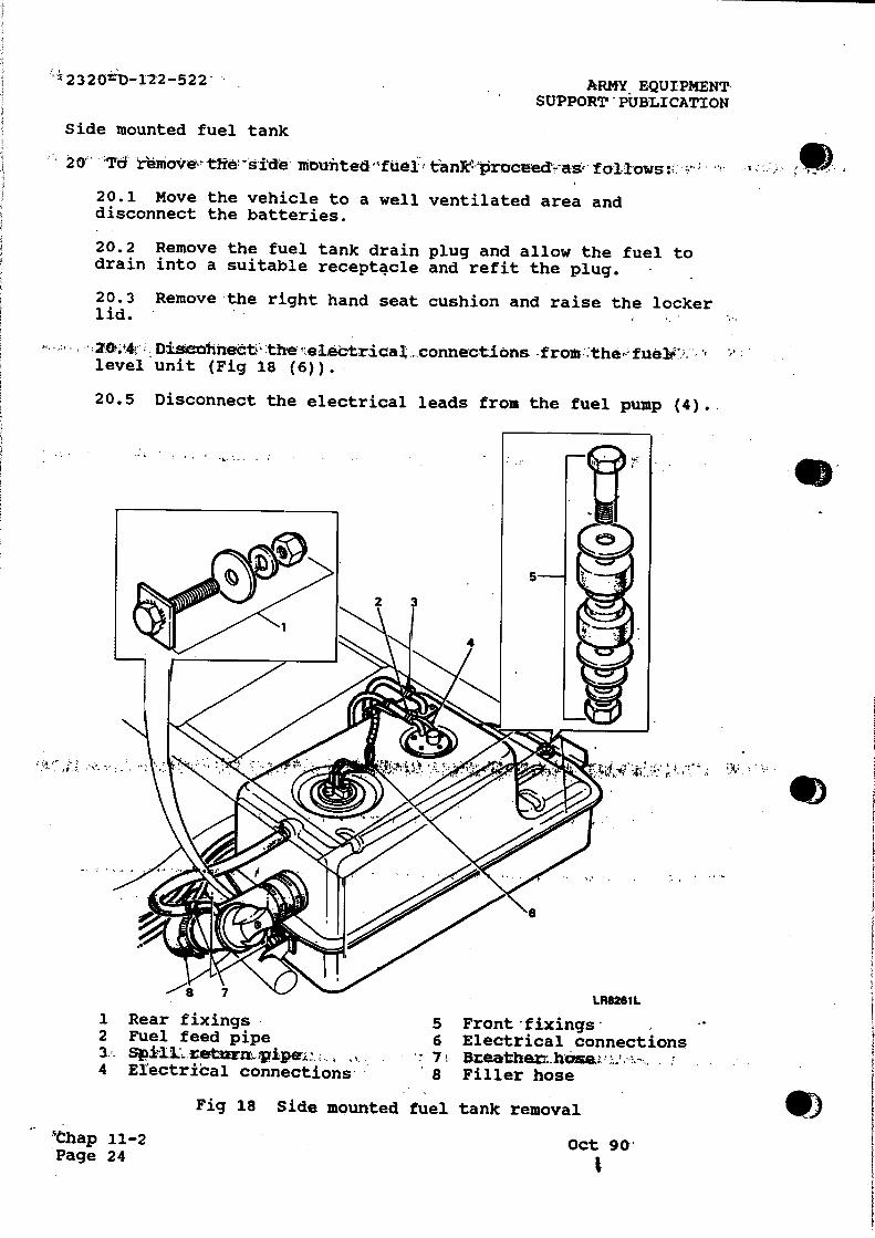
2320ziD-12-2-522- ARMY EQUIPMENT SUPPORT-PUBLICATION
Side mounted fuel tank
remove vie ,. -Side nibmited tanTeVroceed-r•ae,' follows v:
20.1 Move the vehicle to a well ventilated area and disconnect the batteries.
20.2 Remove the fuel tank drain plug and allow the fuel to drain into a suitable receptacle and refit the plug.
20.3 Remove the right hand seat cushion and raise the locker lid.
• 20t.i4; Discohnect' the. electrical _connections from ,the,-fuelv", '• level unit (Fig 18 (6)).
20.5 Disconnect the electrical leads from the fuel pump (4)..
..-""g LR8261L
1 Rear fixings 5 Front 'fixings2 Fuel feed pipe 6 Electrical connections 3 r Spill.. reiturm;pipe,.. , , . 7' Breathert.hose, ,; --4 Electrical connections 8 Filler hose
_Map 11-2 Page 24
Fig 18 Side mounted fuel tank removal
I
Oct 90'
so

'ARMY EQUIPMENT ' 2320-D-122-522
SUPPORT PUBLICATION.
20.6 Detach the fuel feed pipe from the outlet connection on
top of the tank (2).
20.7 Detach the spill return pipe from the connection on top
of the tank (3).
20.8 Slacken the clips at the tank connections of the filler
(8) and breather hoses (7) and disconnect the hoses.
20.9 Detach the front (5) and rear fixings (1) and remove the
tank from below the vehicle.
Fuel level unit
21 Rear mounted fuel tank. To remove the fuel level unit from
rear mounted fuel tanks refer to Cat 522 Chap 11-1 Para 81.
22 Side mounted fuel tank. To remove the fuel level unit from
side mounted fuel tanks refer to Cat 522 Chap 11-1 Para 80.
Fuel pump
23 To remove the fuel pump proceed as follows:
Note ...
The removal procedure for the fuel pump from both rear and
side fuel tanks is identical. However, the rear tank has to be
removed from the vehicle to allow fuel pump removal.
23.1 Remove the five retaining screws (Fig 19 (1)) and
withdraw the fuel pump (3) and sealing ring (2) from the tank.
23.2 Cover the pump aperture in the tank to prevent the
ingress of foreign matter.
Note ...
The fuel pump is a non-repairable item and in the event of
failure must be replaced.
Refitting
'Side and rear mounted fuel tanks
24 If a new tank is being fitted remove the fuel level unit,
spill return elbow, fuel feed elbow (side tank only) and drain
plug from the existing tank and fit them to the replacement tank,
using new sealing washers and joint gaskets as applicable. Fit
the new tank in reverse order of the removal procedure.
Oct 90 Chap 11-2 Page 25

2320-D-122-522
Fuel pump
25 TO fit -the- tiler 'pump- PrOOeect'is follows s
CAUTION . ..
ARMY' EQUIPMENT SUPPORT PUBLICATION,
on some early models a modification was carried out to the fuel pump to prevent the possibility of the contacts earthing. These pumps can be identified by a black plastic tie clip as illustrated. If the fuel tank only is being renewed and the original pump is being refitted. ensure that the tie clip is correctly positioned.
1/4 Pit -the into 'the tit .* with. .a . new seating 19 (2)) and secure with the five screws.(1)
Note...
On rear tanks the outlet pipe should be directed towards thw front. of the, ,vehicle and::the.:electrical i.connections to the rear. On side tanks the outlet pipe should be directed towards the left hand side of the vehicle and the electrical connections to the right.
FUEL FILTER
26 The procedure for removal/installation of the fuel filter is self evident, when removing note should be made of the pipe connections to assist with installation. For renewal of the paper element filter refer to Cat 201.
VAPOUR SEPARATOR
27 The vapour separator is a non-repairable item and in the event of failure must be replaced.
SOLENOID VALVE
- • - 28' The sa,Lenoid valve is - a' non-repairabld- item and- in , the event of failure must be replaced.
NON-RETURN VALVE
29 The non-return valve is a non-repairable item and in the
Chap 11-2 Page 26
Oct 90

ARMY EQUIPMENT
SUPPORT'PUBLICATION
1 Retaining screws 3 Fuel pump
2 Seal
Fig 19 Fuel pump removal
Oct 90
2320-D-122-522
LIU12621.
Chap 11-2 Page.27

ARMY EQUIPMENT SUPPORT PUBLICATION :
EXHAUST SYSTEM
RembVal -
30 To remove the exhaust system proceed as follows:
WARNINGS ...
(1) THE EXHAUST SYSTEM COMPONENTS WILL BECOME EXTREMELY HOT WHEN THE ENGINE IS RUNNING. IN ORDER TO PREVENT THE POSSIBILITY OF SEVERE PERSONAL BURNING, ADEQUATE TIME MUST BE ALLOWED FOR THE SYSTEM TO COOL, BEFORE WORK IS UNDERTAKEN.
(2) ENSURE THE VEHICLE IS SAFELY POSITIONED ON RAMPS BEFORE ANY WORK IS ATTEMPTED FROM THE UNDERSIDE.
30.1 Remove the nuts (Fig 20 (1)) from the exhaust manifold studs.
30.2 Release the flanged plate• (2) and'separate'the.rJr. down tube (4) from the exhaust manifold flange.
30.3 Remove and discard the olive (3).
30.4 Repeat the procedure for separation of the l.h. down tube (22).
30.5 Support the exhaust system and remove the nuts (7),(16) and washers (8),(17) from the. '11, clamps bolts. (10),(18).
30.6 Withdraw the 'U' clamp bolts from the clamp brackets.
30.7 Carefully remove the exhaust system from the support.
30.8 If necessary, remove the clamp brackets (9),(19) and rubber mountings (6),(20) from the chassis.
30%9t: If, requ er-extIMMmAr vyarteniilvaniotWieddf-th iepariieee the following locations by the methods described:
30.9.1 Separate theer.h;down'tube%(4) from _the' r.h. 'Y'' piece tube connection, located mid-way between the r.h. heatshield (23) and the 'Y' piece clamp (19). Remove the auts,.washers and 'U' clamp, and withdraw. the down tube...
30.9.2 Separate the l.h. down tube (22) from the l.h. 'Y' piece tube connection, located beneath the l.h. heatshield (21). Remove the, heatshield, nuts, washers and 'IP clamp and withdraw the down tube.
30.9.3 Separate the rear of the 'Y' piece tube from the first silencer tube connection. Remove the nuts (14), washers (13) and bolts (11), and withdraw the- 0Y' piece tube connection. Remove and discard the olive (12)..
30.9.4 Separate first and second silencers at th connection to the rear of the -first- silencer ,adopting the procedure instructed in Para 30.9.3.
--Chap 11-2 Page 28
Oct 90

ARMY EQUIPMENT • 2320-D-122-522
SUPPORT PUBLICATION
Note ...
An extension tube (5) is fitted to the rear of the 'Y'
piece tube to accommodate the increased chassis length
of Land Rover 127 vehicles. The separation procedure is
identical to that instructed in Para 30.9.3.
Refitting
31 To fit the exhaust system, reverse the removal procedures
instructed in Para 30.
Note ...
The type of tube jointing arrangement adopted, allows the
exhaust system to be assembled loosely before securing to the
vehicle. This enables easier fitting and ensures that no
component,is subjected to undue stress. Replace any discarded
olives and also apply firegum putty to any separated tube
connections referred to in Para 30.9.1 and 30.9.2 before
reassembly.
WARNING ...
ENSURE THE VEHICLE IS SAFELY POSITIONED ON RAMPS BEFORE ANY
WORK IS ATTEMPTED FROM THE UNDERSIDE.
Oct•90 Chap 11-2 Page 29
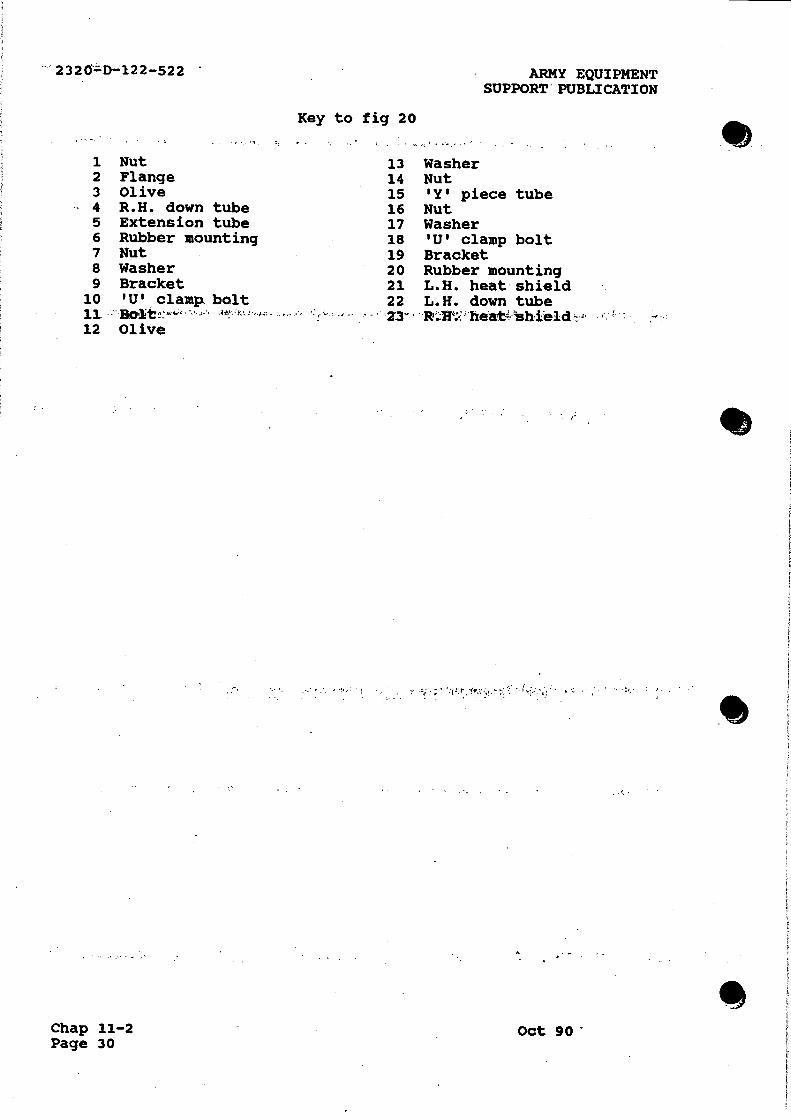
- 2320'=D-;122-522
1 Nut 2 Flange 3 Olive 4 R.H. down tube 5 Extension tube
Key to fig 20
13 14 15 16 17
ARMY EQUIPMENT SUPPORT" PUBLICATION
Washer Nut 'Y' piece tube Nut Washer
6 Rubber mounting 18 'U' clamp bolt 7 Nut 19 Bracket 8 Washer 20 Rubber mounting 9 Bracket 21 L. H . heat shield 10 'U' clamp bolt 22 L.H. down tube 11 -Bolt-,‘ • 4 t! #-• • 23- Rar:: hea shield 12 Olive
Chap 11-2 Page 30
Oct 90

ARMY EQUIPMENT
SUPPORT PUBLICATION
Fig 20
Oct 90
Exhaust system
2320-D-122-522
Fig 20
Chap 11-2
Page 31/32

L s 8

ARMY EQUIPMENT 2320-D-122-522
SUPPORT PUBLICATION
Chapter 11-3
PULSAIR SYSTEM (DEBATED ENGINES)
CONTENTS
Frame Para
1 Introduction Pulsair manifold
2 Removal 3 Refitting
Pulsair check valve 4 Removal 5 Examination 6 Refitting
Fig
1 Removal of the Pulsair manifold
2 Removal of the check valve
3 Section through check valve
INTRODUCTION
1 This chapter details the Unit and Field repairs for the
pulsair system fitted to the derated 3.5 litre V8 engine
installed in Land Rover 110 vehicles.
PULSAIR MANIFOLD
Removal
2 To remove the pulsair manifolds proceed as follows:
2.1 Release the hose clip (Fig 1 (1)) securing the hose (2)
at the air intake elbow.
2.2 Pull the hose from the elbow.
2.3 Release the check valve (3) from the manifold.
2.4 Release the manifold (4) from the cylinder head.
2.5 Lift off the manifold.
2.6 Remove the threaded inserts (5) from the cylinder head.
2.7 Using a piece of bent wire, retrieve the spargas tube (6)
from the bottom of the insert bore.
Refitting
3 To refit the pulsair manifold reverse the removal procedure
ensuring that the threaded double ended insert (7) is fitted with
the plain shank nearest the cylinder head.
3.1 Run the engine and check for air leaks at the manifold.
Oct 90 Chap 11-3
Page 1

2320_77D'-122-522
\ 4,‘ 1 Clip 2 Hose 3 Union 4 Manifold
ARMY EQUIPMENT. SUPPORT` PUBLICATION
4 5 Threaded insert 6 Spargas tube 7 Shank
Fig 1 Removal of the pulsair manifold
PULSAIR CHECK VALVE
Removal c
4 To remove the pulsair check valve proceed as follows:
4.1 Disconnect the hose (Fig 2 (1)) from the check valve.
4.2 Using two open-ended spanners, one on the pulsair manifdId hexagon 'to support the manifold,"aftd-the other to remove. the. valve anti-clockwise.
CAUTION ...
Do not impose any strain on the air manifold.
Examination
1-••.- 4 .
5 With the check valve removed, blow through the valve orally in both directions in turn. Air should only pass through the valve whenf b-lown, from, the: hoses .ubnnectzion--enth 'ShOurrd - a in-pass-through- - the valve when blown from the air manifold end, the valve should be replaced.
...Chap 11-3 Page 2
.90

S
ARMY EQUIPMENT SUPPORT PUBLICATION
1 Hose 2 Union
Fig 2 Removal of the check valve
2320-D-122-522
Ref ittina
6 Refitting the check valve is the reverse- of the removal
procedure.
1 Direction of flow
. Oct_ 90
2 Valve diaphragm
Fig 3 Section through check valve
Chap.11-3 Page 3/4

•.e..•6;' A
r.