aries ife safety talk 901 - · update on ife safety work for aries david petti ... (150 to...
TRANSCRIPT
Idaho National Engineering and Environmental Laboratory
Update on IFE SafetyWork for ARIES
David PettiFusion Safety Program
ARIES e-meetingOctober 17, 2001
Idaho National Engineering and Environmental Laboratory
Several safety issues for IFE designsare being studied• Target fabrication safety and reliability issues• Risk assessment accident-initiating events• Coolant hazards (Sn, Pb, Sn-25Li)
– Chemical reactivity– Chemical toxicity– Radiological hazards
• Aerosol considerations for chamber clearing
Idaho National Engineering and Environmental Laboratory
Manufacturing industry input for IFEtarget fabrication• INEEL and GA personnel visited Micron Technology
(Boise, ID) on July 18 to gather information aboutmanufacturing processes for precision, high quality,large scale production.
• Highlights of the Micron facility:– produces on the order of 400,000 chips/day– clean room facilities are large and expensive (i.e.,
$3k/foot2).– 1.5 mile tour to visit the manufacturing stations
• Micron staff members were enthused about potentialcollaboration(s) to support IFE target manufacture.

Idaho National Engineering and Environmental Laboratory
Industry input on manufacturingquality assurance• Quality Assurance data about the Micron facilities:
– an initial production run may have 50% defects,while a mature run has less than 10% defects.
– batches from an initial production run are tested upto 130 hrs while mature runs are tested up to 10 hrs.
– an estimated four to five “end user product” returnsper million units distributed.
– facility support services are tightly controlled tomaintain manufacturing quality.
– electrostatic suppression and discharge are veryimportant for maintaining high-quality production.
Idaho National Engineering and Environmental Laboratory
Accident initiating events are beingcompiled for IFE designs• Current initiator work is focused on the SOMBRERO
design.– SOMBRERO is representative of dry wall, laser driver
IFE design concepts• A master logic diagram (MLD) for SOMBRERO has been
drafted and is under review. The MLD is a plant-levelfault tree of potential hazardous releases.
• An MLD for the HYLIFE II plant design has been initiatedand will be completed later this year.– HYLIFE II is representative of liquid wall, ion beam
driver IFE design concepts
Idaho National Engineering and Environmental Laboratory
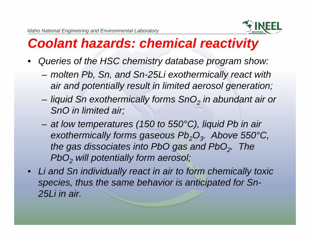
Coolant hazards: chemical reactivity• Queries of the HSC chemistry database program show:
– molten Pb, Sn, and Sn-25Li exothermically react withair and potentially result in limited aerosol generation;
– liquid Sn exothermically forms SnO2 in abundant air orSnO in limited air;
– at low temperatures (150 to 550°C), liquid Pb in airexothermically forms gaseous Pb2O3. Above 550°C,the gas dissociates into PbO gas and PbO2. ThePbO2 will potentially form aerosol;
• Li and Sn individually react in air to form chemically toxicspecies, thus the same behavior is anticipated for Sn-25Li in air.
Idaho National Engineering and Environmental Laboratory
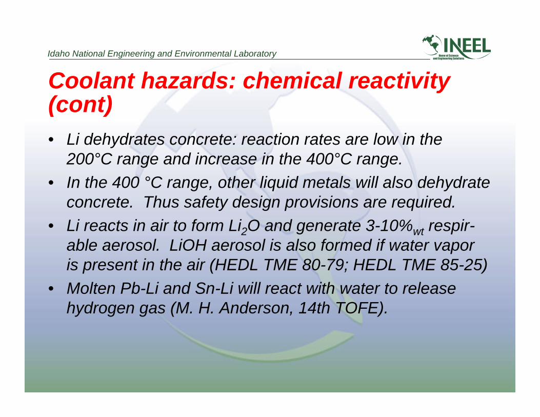
Coolant hazards: chemical reactivity(cont)• Li dehydrates concrete: reaction rates are low in the
200°C range and increase in the 400°C range.• In the 400 °C range, other liquid metals will also dehydrate
concrete. Thus safety design provisions are required.• Li reacts in air to form Li2O and generate 3-10%wt respir-
able aerosol. LiOH aerosol is also formed if water vaporis present in the air (HEDL TME 80-79; HEDL TME 85-25)
• Molten Pb-Li and Sn-Li will react with water to releasehydrogen gas (M. H. Anderson, 14th TOFE).
Idaho National Engineering and Environmental Laboratory
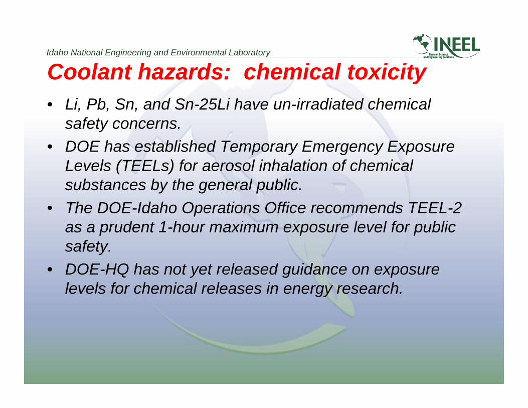
Coolant hazards: chemical toxicity• Li, Pb, Sn, and Sn-25Li have un-irradiated chemical
safety concerns.• DOE has established Temporary Emergency Exposure
Levels (TEELs) for aerosol inhalation of chemicalsubstances by the general public.
• The DOE-Idaho Operations Office recommends TEEL-2as a prudent 1-hour maximum exposure level for publicsafety.
• DOE-HQ has not yet released guidance on exposurelevels for chemical releases in energy research.
Idaho National Engineering and Environmental Laboratory
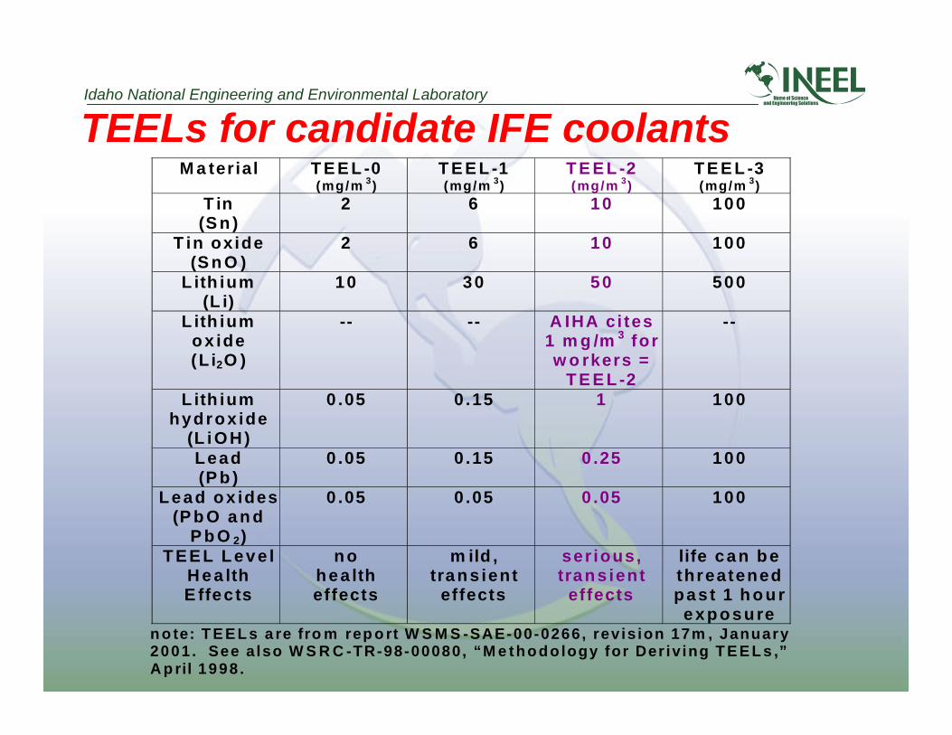
TEELs for candidate IFE coolantsM a terial T E E L -0
(mg/m 3)T E E L -1(mg/m 3)
T E E L -2(mg/m 3)
T E E L -3(mg/m 3)
T in(S n )
2 6 10 100
T in oxide(S n O )
2 6 10 100
L ith ium(L i)
10 30 50 500
L ith iumox ide(L i2O )
-- -- A IHA c i tes1 m g /m 3 forw o rkers =
T E E L -2
--
L ith iumhydrox ide
(L i O H )
0 .05 0 .15 1 100
Lead(P b )
0 .05 0 .15 0 .25 100
Lead ox ides(P b O a n d
P b O 2)
0 .05 0 .05 0 .05 100
T E E L L e v e lH e a lthE ffec ts
n ohea ltheffects
m ild ,trans ient
effects
ser ious,trans ient
effects
life can bethreatenedpast 1 h o u r
exposuren o te: T E E L s a re fro m rep o rt W S M S -SAE-00-0266, rev is ion 17m , January2001 . See a lso W S R C -TR-98-00080, “M e thodo logy for Der iv ing T E E L s ,”A p ril 1998 .
Idaho National Engineering and Environmental Laboratory
Coolant hazards: radiological concerns• A radiological-based analysis of the coolants focused on
five factors:– Decay heat generation: influences accident response– Contact dose (gamma): influences worker safety and
maintenance– Vapor pressure: volatility under air in steam ingress
condition– Radiotoxicity: identifies the isotopes whose activity
levels produce radiation concerns– Class C waste: identifies materials that can meet the
low level waste criteria

Idaho National Engineering and Environmental Laboratory
Decay heat comparison
From: C.B.A. Forty et. al., Handbook of Fusion Activation Data, Part 1, AEA FUS 180, May 1992 and Part 2, AEA FUS 232,May 1993, AEA Technology Fusion, Culham Laboratory, Abingdon, Oxon.
10-14 10-12 10-10 10-8 10-6 10-4 10-2 100
Sn
Sn-25Li
V
Pb
Li (w/o H3)
100 years10 years1 hour
Decay Heat at the First Wall (W/g)

Idaho National Engineering and Environmental Laboratory
Contact dose (gamma) comparison
From: C.B.A. Forty et. al., Handbook of Fusion Activation Data, Part 1, AEA FUS 180, May 1992 and Part 2, AEA FUS 232,May 1993, AEA Technology Fusion, Culham Laboratory, Abingdon, Oxon. R. Haange et al., “Remote Handling Maintenanceof ITER,” Fusion Energy 1998, Proceedings of the 17th IAEA Fusion Energy Conference, Yokohama, Japan, 18-24 October1998, 3, pgs 965-972
10-14 10-12 10-10 10-8 10-6 10-4 10-2 100 102 104
Sn
Sn-25Li
Pb
Li (w/o H3 )
100 years10 years
Contact Dose at the Shield (Sv/hr)
10CFR835upper limithands-on
1 Sv = 100 Rem
DOE1098-99upper limithands-on
Snowmass-99remote handling
(2628 Sv/lifetime)
R. HaangeRemote Handling
(8 x 10⁹ Sv/lifetime)
Idaho National Engineering and Environmental Laboratory
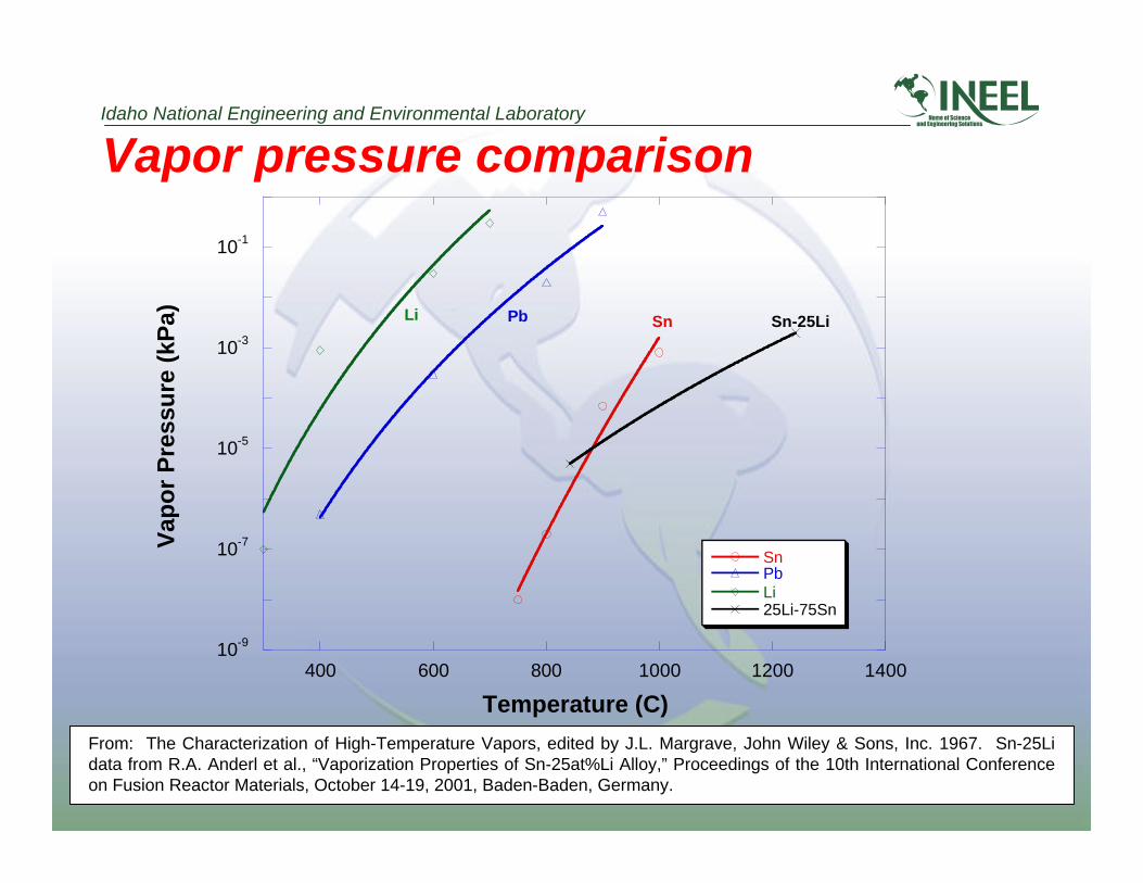
Vapor pressure comparison
From: The Characterization of High-Temperature Vapors, edited by J.L. Margrave, John Wiley & Sons, Inc. 1967. Sn-25Lidata from R.A. Anderl et al., “Vaporization Properties of Sn-25at%Li Alloy,” Proceedings of the 10th International Conferenceon Fusion Reactor Materials, October 14-19, 2001, Baden-Baden, Germany.
10-9
10-7
10-5
10-3
10-1
400 600 800 1000 1200 1400
SnPbLi25Li-75Sn
Vap
or
Pre
ssu
re (
kPa)
Temperature (C)
Sn-25LiPbLi Sn
Idaho National Engineering and Environmental Laboratory
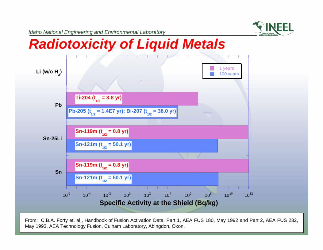
Radiotoxicity of Liquid Metals
From: C.B.A. Forty et. al., Handbook of Fusion Activation Data, Part 1, AEA FUS 180, May 1992 and Part 2, AEA FUS 232,May 1993, AEA Technology Fusion, Culham Laboratory, Abingdon, Oxon.
Sn
Sn-25Li
Pb
Li (w/o H3) 100 years
1 years
10-6 10-4 10-2 100 102 104 106 108 1010 1012
Specific Activity at the Shield (Bq/kg)
Sn-119m (t1/2
= 0.8 yr)
Ti-204 (t1/2
= 3.8 yr)
Pb-205 (t1/2
= 1.4E7 yr); Bi-207 (t1/2
= 38.0 yr)
Sn-121m (t1/2
= 50.1 yr)
Sn-119m (t1/2
= 0.8 yr)
Sn-121m (t1/2
= 50.1 yr)

Idaho National Engineering and Environmental Laboratory
1
H
3
Li4
Be
11
Na
12
Mg
19
K
20
Ca
21
Sc
22
Ti
23
V
37
Rb
39
Y
40
Zr
41
Nb
55
Cs
56
Ba
57
La
73
Ta
24
Cr
42
Mo
74
W
25
Mn
26
Fe
28
Ni
46
Pd
47
Ag
30
Zn
48
Cd
5
B
31
Ga
49
In
6
C
14
Si
32
Ge
50
Sn
15
P
33
As
8
O
52
Te
9
F
53
I
69
Tm
68
Er
66
Dy
65
Tb
63
Eu
60
Nd
59
Pr
no stable
isotopes
83
Bi
82
Pb
81
Tl
79
Au
77
Ir
no stable
isotopes
70
Yb
72
Hf
27
Co
45
Rh
44
Ru
13
Al
7
N
17
Cl
16
S
29
Cu
34
Se
38
Sr
51
Sb
75
Re
76
Os
78
Pt
80
Hg
58
Ce
6 2
Sm
35
Br
64
Gd
67
Ho
71
Lu
unlimited 10% 1% .1% .01% .001% .0001%
Top half of box: hard spectrum Bottom half of box: soft spectrum
.00001%
Limits on Elements for Class C WasteQualification
From: S.J. Piet, et al., “Initial Integration of Accident Safety, Waste Management, Recycling, Effluent, and MaintenanceConsiderations for Low-Activation Materials”, Fusion Technology, Vol. 19, Jan. 1991, pp. 146-161. Assumes 5 MW/m2 for 4years; and E. T. Cheng, “Concentration Limits of Natural Elements in Low Activation Materials”, presented at ICFRM-8,Sendai, Japan,October 1997

Idaho National Engineering and Environmental Laboratory
Inventory-based radiotoxicity
Metric(Sv) =Σ [Inventory (Ci)*Radiotoxicity(Sv/Ci)]
1.00E-01
1.00E+00
1.00E+01
1.00E+02
1.00E+03
1.00E+04
Gold Tungsten Lead Platinum Palladium Silver
TargetChamber FW
Inventory based Dose Metric (Sv) for Laser IFE
1.00E-01
1.00E+00
1.00E+01
1.00E+02
1.00E+03
1.00E+04
1.00E+05
Gold/Gd Hg Ta Hg/W/Cs Pb/Hf Pb/Ta/Cs
TargetChamber FW
Inventory based Dose Metric (Sv) for Heavy Ion Fusion
Idaho National Engineering and Environmental Laboratory
Aerosol considerations for chamberclearing
• Issues of aerosol generation and transport– Aerosol conservation model– Representative nucleation and growth rates– Particle transport– Particle deposition
• Future work

Idaho National Engineering and Environmental Laboratory
Aerosol conservation model• Evolution of the aerosol size distribution is governed
by the aerosol General Dynamic Equation (GDE):
• This equation demonstrates aerosol particleconservation, where n is the number of particles perunit particle volume per unit gas volume.
( ) ( )∂∂
ν∂∂
∂∂
∂∂
nt
n D n cnnt
nt
ntgrowth growth
+ ∇⋅ − ∇⋅ ∇ + ∇⋅ =
+
+
r r
1 2444444 3444444 1 2444444 3444444Convective Diffusionand Transport
homo hetro coag
Particle Growth andCoagulation
, ,
Idaho National Engineering and Environmental Laboratory
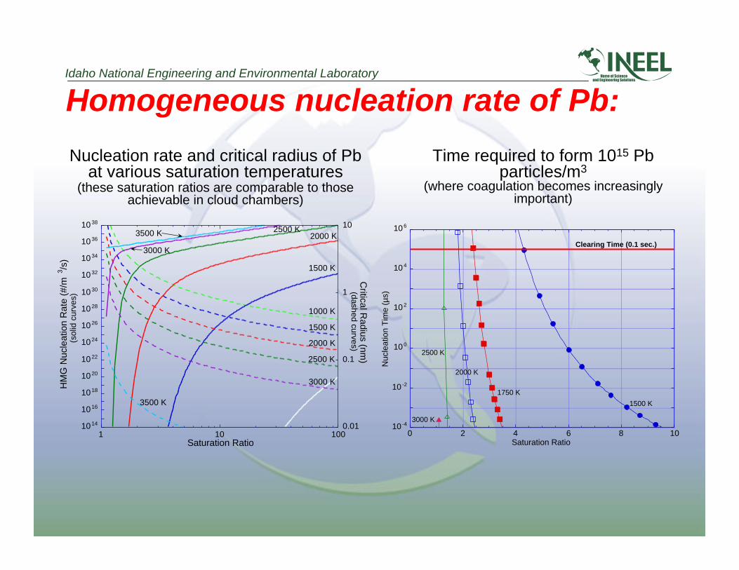
Homogeneous nucleation rate of Pb:
Nucleation rate and critical radius of Pbat various saturation temperatures
Time required to form 1015 Pbparticles/m3
(where coagulation becomes increasinglyimportant)
(these saturation ratios are comparable to thoseachievable in cloud chambers)
10 14
10 16
10 18
10 20
10 22
10 24
10 26
10 28
10 30
10 32
10 34
10 36
10 38
0.01
0.1
1
10
1 10 100
Critical R
adius (nm)
(dashed curves)
HM
G N
ucle
atio
n R
ate
(#/m
3 /s)
(sol
id c
urve
s)
Saturation Ratio
1500 K
2000 K
2500 K
3000 K
1000 K
1500 K
2000 K2500 K
3000 K
3500 K
3500 K
10 -4
10 -2
10 0
10 2
10 4
10 6
0 2 4 6 8 10
Nuc
leat
ion
Tim
e (µ
s)
Saturation Ratio
1500 K
1750 K
2000 K
2500 K
3000 K
Clearing Time (0.1 sec.)

Idaho National Engineering and Environmental Laboratory
Heterogeneous growth and coagulationrate of Pb:Time needed for particles in saturated
vapor to increase volume by 10%Time required for 1 µm dust particles
to change total number by 10%
• Dust particle concentrations generated from homogeneousnucleation are sufficiently large so that particle growth andcoagulation occur faster than chamber clearing times
10 0
10 1
10 2
10 3
10 4
10 5
10 6
0 20 40 60 80 100
Con
dens
atio
n T
ime
(µs)
Saturation Ratio
1500 K
Clearing Time- 0.1 sec.
3500 K
3000 K
2500 K
2000 K
10 -6
10 -5
10 -4
10 -3
10 -2
10 -1
10 0
10 1
10 13 10 14 10 15 10 16 10 17 10 18 10 19 10 20
Tim
e fo
r 10
% C
hang
e (s
ec.)
Initial Number Density (#/m 3)
Clearing Time (0.1 sec.)
Est
imat
ed p
artic
le c
once
ntra
tion
for
hom
ogen
eous
nuc
leat
ion 1000 K
3500 K
Idaho National Engineering and Environmental Laboratory
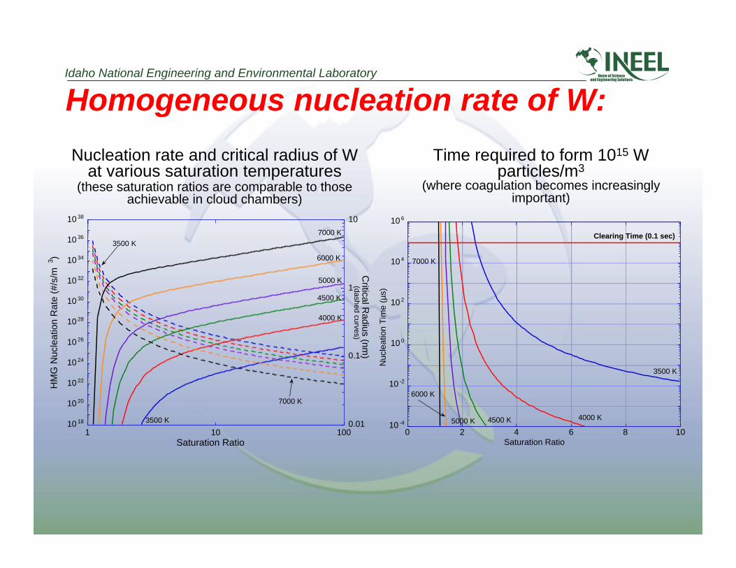
Homogeneous nucleation rate of W:
Nucleation rate and critical radius of Wat various saturation temperatures
Time required to form 1015 Wparticles/m3
(where coagulation becomes increasinglyimportant)
(these saturation ratios are comparable to thoseachievable in cloud chambers)
10 18
10 20
10 22
10 24
10 26
10 28
10 30
10 32
10 34
10 36
10 38
0.01
0.1
1
10
1 10 100
HM
G N
ucle
atio
n R
ate
(#/s
/m3 )
Critical R
adius (nm)
Saturation Ratio
4000 K
6000 K
7000 K
4500 K
5000 K
3500 K
3500 K
7000 K
(dashed curves)
10 -4
10 -2
10 0
10 2
10 4
10 6
0 2 4 6 8 10
Nuc
leat
ion
Tim
e (µ
s)
Saturation Ratio
4000 K
6000 K
7000 K
4500 K5000 K
3500 K
Clearing Time (0.1 sec)
Idaho National Engineering and Environmental Laboratory
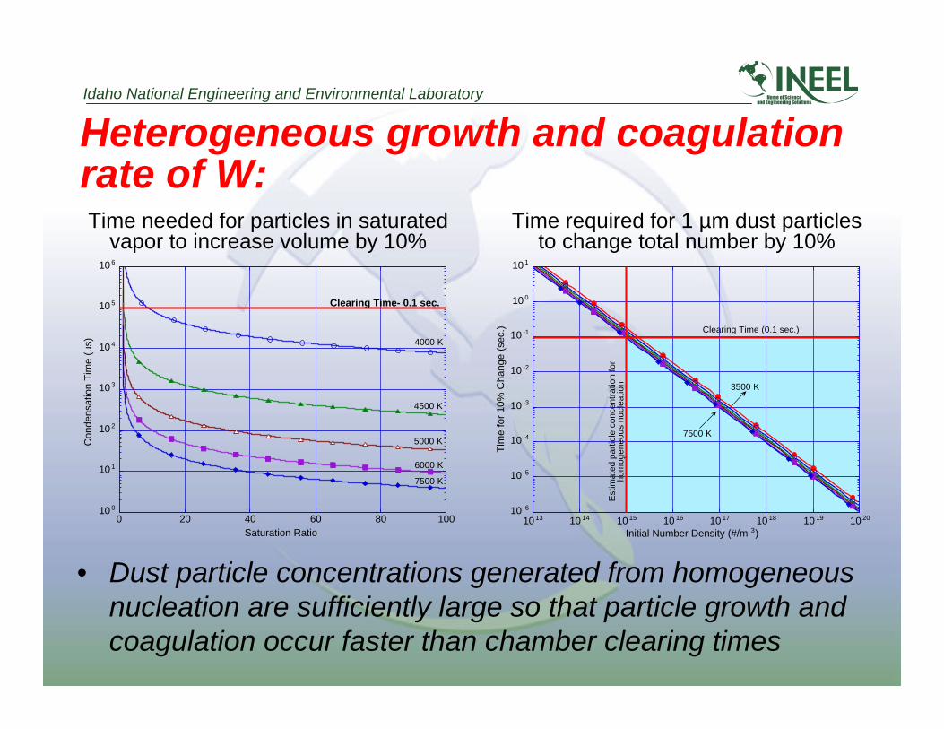
Heterogeneous growth and coagulationrate of W:Time needed for particles in saturated
vapor to increase volume by 10%Time required for 1 µm dust particles
to change total number by 10%
10 0
10 1
10 2
10 3
10 4
10 5
10 6
0 20 40 60 80 100
Con
dens
atio
n T
ime
(µs)
Saturation Ratio
Clearing Time- 0.1 sec.
6000 K
5000 K
4500 K
4000 K
7500 K
10 -6
10 -5
10 -4
10 -3
10 -2
10 -1
10 0
10 1
10 13 10 14 10 15 10 16 10 17 10 18 10 19 10 20
Tim
e fo
r 10
% C
hang
e (s
ec.)
Initial Number Density (#/m 3)
Clearing Time (0.1 sec.)
Est
imat
ed p
artic
le c
once
ntra
tion
for
hom
ogen
eous
nuc
leat
ion 3500 K
7500 K
• Dust particle concentrations generated from homogeneousnucleation are sufficiently large so that particle growth andcoagulation occur faster than chamber clearing times
Idaho National Engineering and Environmental Laboratory
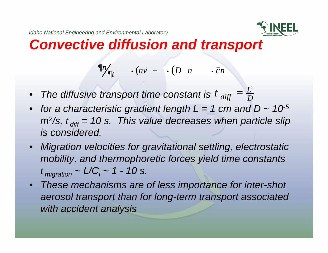
Convective diffusion and transport
• The diffusive transport time constant is• for a characteristic gradient length L = 1 cm and D ~ 10-5
m2/s, τdiff = 10 s. This value decreases when particle slipis considered.
• Migration velocities for gravitational settling, electrostaticmobility, and thermophoretic forces yield time constantsτmigration ~ L/Ci ~ 1 - 10 s.
• These mechanisms are of less importance for inter-shotaerosol transport than for long-term transport associatedwith accident analysis
τdiffLD=
2
∂n
∂t + ∇ • nv v ( ) − ∇ • D∇n( ) + ∇ •v c n

Idaho National Engineering and Environmental Laboratory
Particle deposition
• Deposition via diffusive and/or migratory transport ofparticles are secondary effects for inter-shot aerosoltransport
• inertial deposition and turbulent deposition are importantfor inter-shot aerosol transport because they areresponsible for placing particles at undesired locations,such as on final optics or in ducts.
r J
wall= −D∇n +
r c migration +
r c inertial +
r c turbulent( )n

Idaho National Engineering and Environmental Laboratory
Future work for aerosol formation• Aerosol model requires local state properties (T,P) for
determining nucleation and growth rates. Flow fieldis also needed for particle convection and deposition
• Solve within Hydrodynamic Chamber Model• Modify existing INEEL fluids/aerosol model to
simulate a dry-wall IFE chamber for the purpose ofscoping studies
• Experimental benchmarking