arduinodrawing machine(workshop( andcontest(elb/siggraph/syllabus2014.pdf · arduinodrawing...
TRANSCRIPT

Arduino Drawing Machine Workshop and Contest Drawing machines are computer-‐controlled mechanical constructions that move and make marks on paper. They can be considered kinetic sculptures in their own right, but they also make drawings as they move, producing another type of art as their output.
This is a step-‐by-‐step course in the Studio on how to make the drawing machines, along with some information about the history and practice of making sculptures that draw. This type of kinetic, performative drawing sculpture has been explored by a wide variety of artists from the 18th century onwards.
Logistics: All activities will be in the SIGGRAPH Studio
• Initial course – Sunday, August 10, 12:30-‐5:15 • Drop-‐in Project Space – Monday, Tuesday, Wednesday during regular Studio hours • Gallery and Competition – Wednesday, August 13, 4:00pm
There will be a cash bar at the event and the Arduino drawing machines will be judged on their overall design, function, and drawing produced by both the crowd and a special guest judge. There will be prizes!
• This workshop is first come will be first served and supplies are limited. The Sunday course participants will have priority for available hardware.
Instructors: Erik Brunvand, School of Computing, University of Utah ([email protected]) Ginger Alford, Trinity Valley School, Ft. Worth, TX ([email protected]) Paul Stout, Dept. of Art and Art History, Univ. of Utah ([email protected])
Motivation: Arduino and microcontrollers like it have invigorated students, hobbyists, and makers of all types to add electronics and computer control to their hand-‐made contraptions. The integration of electronics and electro-‐mechanical components with computer control is known more generally as physical computing.
A concise definition from Wikipedia is: Physical computing, in the broadest sense, means building interactive physical systems by the use of software and hardware that can sense and respond to the analog world.
For artists, this provides tools that enable interaction with people and the environment. For engineers, this is an exciting and novel creative context for technology. For educators, this is a powerful way to introduce programming and physical computing concepts to students from high school to undergraduate and to students who might not normally be intrigued by a computer engineering course. The workshop will include a brief introduction to Drawing Machines, establishing a creative and artistic context in which the technical content will be explored in the workshop. Workshop participants will build (in teams) a simple drawing machine using foam core, nuts/bolts, and
masking tape. The machine will be controlled using potentiometers and servos connected to an Arduino microcontroller. Topics that are covered by this activity include basics of microcontroller programming and electronic components, including how to use a breadboard, how to read a circuit diagram and how to interact with the physical world using programmatic control of a variety of input and output components. Once the simple prototype has been constructed, teams will have the opportunity to modify, enhance, and explore their machine’s operation to optimize both the machine’s appearance, and the drawings that are made by their machine. The gallery event on Wednesday will be a chance to show off both the machines and the drawings made by the machines. Our experience is that the machines make relatively interesting drawings very quickly, but they make their most interesting drawings if they’re left to operate on their own for an extended period of time. A few lines are interesting. A huge number of lines can be very interesting.
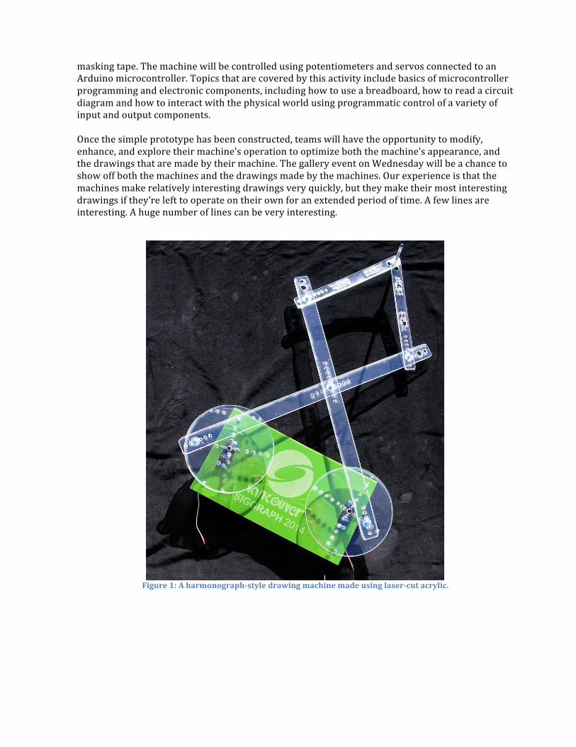
Figure 1: A harmonograph-‐style drawing machine made using laser-‐cut acrylic.
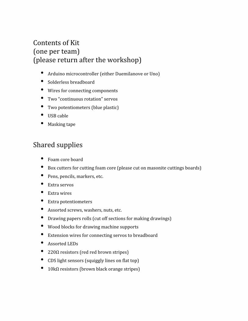
Contents of Kit (one per team) (please return after the workshop)
• Arduino microcontroller (either Duemilanove or Uno) • Solderless breadboard • Wires for connecting components • Two “continuous rotation” servos • Two potentiometers (blue plastic) • USB cable • Masking tape
Shared supplies
• Foam core board • Box cutters for cutting foam core (please cut on masonite cuttings boards) • Pens, pencils, markers, etc. • Extra servos • Extra wires • Extra potentiometers • Assorted screws, washers, nuts, etc. • Drawing papers rolls (cut off sections for making drawings) • Wood blocks for drawing machine supports • Extension wires for connecting servos to breadboard • Assorted LEDs • 220Ω resistors (red red brown stripes) • CDS light sensors (squiggly lines on flat top) • 10kΩ resistors (brown black orange stripes)
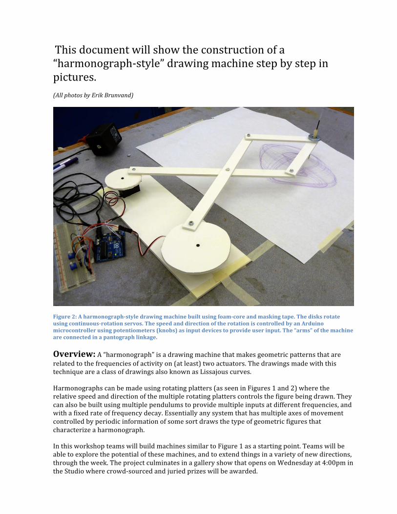
This document will show the construction of a “harmonograph-‐style” drawing machine step by step in pictures. (All photos by Erik Brunvand)
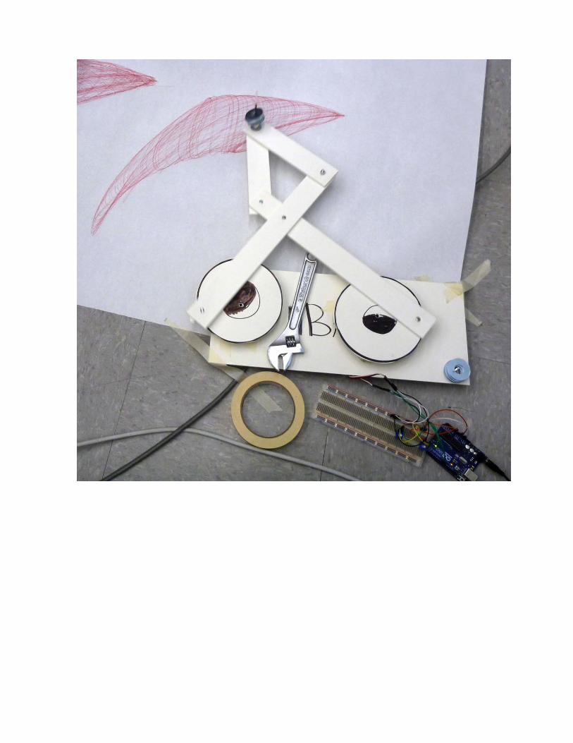
Figure 2: A harmonograph-‐style drawing machine built using foam-‐core and masking tape. The disks rotate using continuous-‐rotation servos. The speed and direction of the rotation is controlled by an Arduino microcontroller using potentiometers (knobs) as input devices to provide user input. The “arms” of the machine are connected in a pantograph linkage.
Overview: A “harmonograph” is a drawing machine that makes geometric patterns that are related to the frequencies of activity on (at least) two actuators. The drawings made with this technique are a class of drawings also known as Lissajous curves.
Harmonographs can be made using rotating platters (as seen in Figures 1 and 2) where the relative speed and direction of the multiple rotating platters controls the figure being drawn. They can also be built using multiple pendulums to provide multiple inputs at different frequencies, and with a fixed rate of frequency decay. Essentially any system that has multiple axes of movement controlled by periodic information of some sort draws the type of geometric figures that characterize a harmonograph.
In this workshop teams will build machines similar to Figure 1 as a starting point. Teams will be able to explore the potential of these machines, and to extend things in a variety of new directions, through the week. The project culminates in a gallery show that opens on Wednesday at 4:00pm in the Studio where crowd-‐sourced and juried prizes will be awarded.
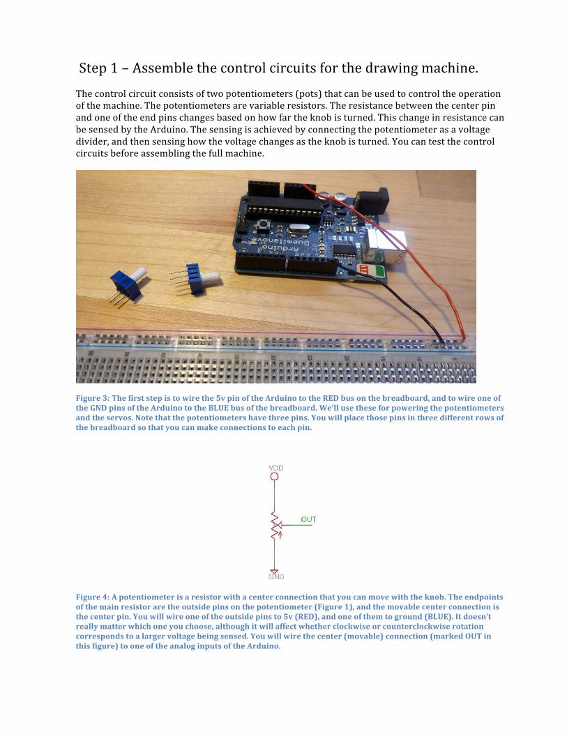
Step 1 – Assemble the control circuits for the drawing machine. The control circuit consists of two potentiometers (pots) that can be used to control the operation of the machine. The potentiometers are variable resistors. The resistance between the center pin and one of the end pins changes based on how far the knob is turned. This change in resistance can be sensed by the Arduino. The sensing is achieved by connecting the potentiometer as a voltage divider, and then sensing how the voltage changes as the knob is turned. You can test the control circuits before assembling the full machine.
Figure 3: The first step is to wire the 5v pin of the Arduino to the RED bus on the breadboard, and to wire one of the GND pins of the Arduino to the BLUE bus of the breadboard. We’ll use these for powering the potentiometers and the servos. Note that the potentiometers have three pins. You will place those pins in three different rows of the breadboard so that you can make connections to each pin.
Figure 4: A potentiometer is a resistor with a center connection that you can move with the knob. The endpoints of the main resistor are the outside pins on the potentiometer (Figure 1), and the movable center connection is the center pin. You will wire one of the outside pins to 5v (RED), and one of them to ground (BLUE). It doesn’t really matter which one you choose, although it will affect whether clockwise or counterclockwise rotation corresponds to a larger voltage being sensed. You will wire the center (movable) connection (marked OUT in this figure) to one of the analog inputs of the Arduino.
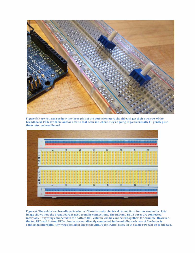
Figure 5: Here you can see how the three pins of the potentiometers should each get their own row of the breadboard. I'll leave them out for now so that I can see where they're going to go. Eventually I'll gently push them into the breadboard.
Figure 6: The solderless breadboad is what we'll use to make electrical connections for our controller. This image shows how the breadboard is used to make connections. The RED and BLUE buses are connected internally – anything connected to the bottom RED column will be connected together, for example. However, the top RED and bottom RED columns are not directly connected. In the middle, each row of five holes is connected internally. Any wires poked in any of the ABCDE (or FGHIJ) holes on the same row will be connected.

Figure 7: Here I've wired the right pin of each pot to the RED (5v) bus, and the left pin of each one to the BLUE (ground) bus. I've used red wires for 5v and black wires for ground just to help keep things straight, but of course it doesn’t matter what color wires you use.
Figure 8: Here I've wired the center pin of each pot to an analog input of the Arduino. I've wired the right pot to analog pin A0 with the green wire, and the left pot to analog pin A1 with the orange wire.
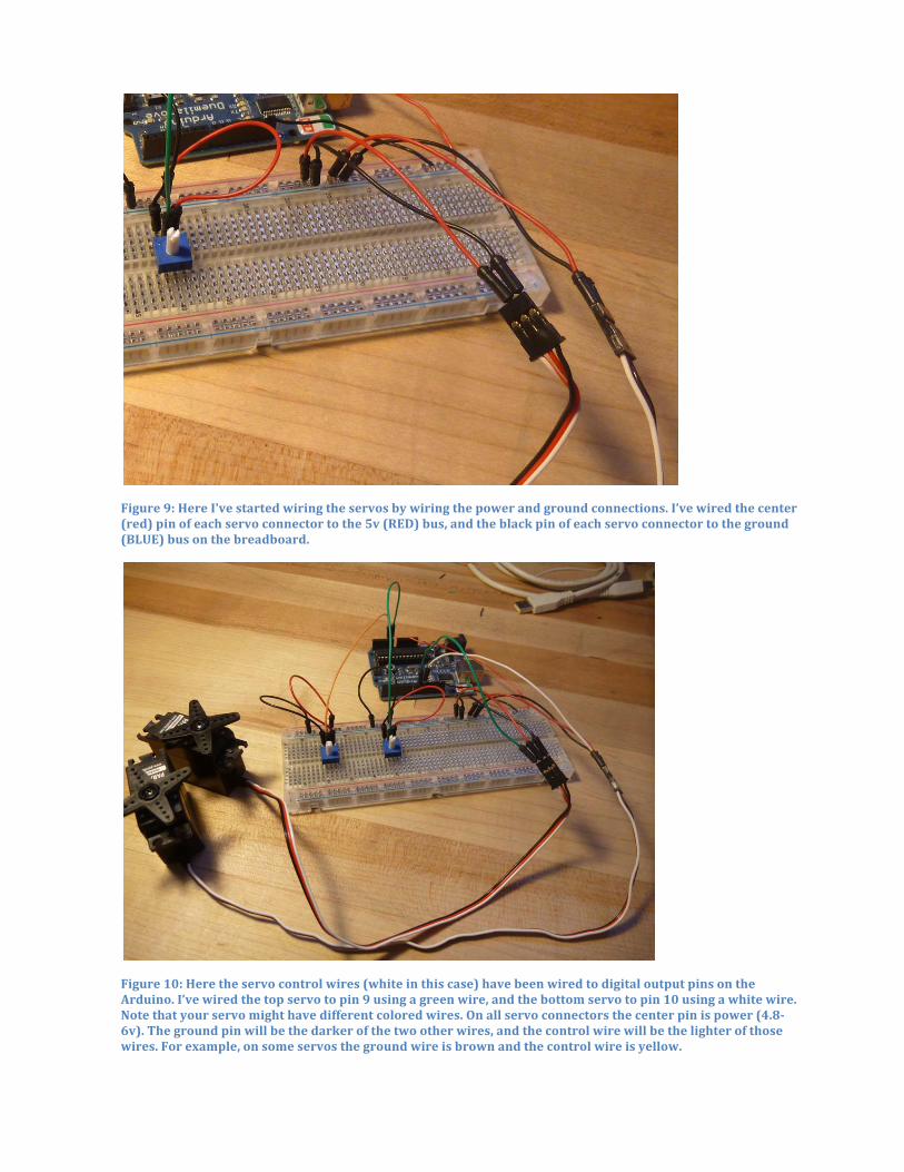
Figure 9: Here I've started wiring the servos by wiring the power and ground connections. I’ve wired the center (red) pin of each servo connector to the 5v (RED) bus, and the black pin of each servo connector to the ground (BLUE) bus on the breadboard.
Figure 10: Here the servo control wires (white in this case) have been wired to digital output pins on the Arduino. I’ve wired the top servo to pin 9 using a green wire, and the bottom servo to pin 10 using a white wire. Note that your servo might have different colored wires. On all servo connectors the center pin is power (4.8-‐6v). The ground pin will be the darker of the two other wires, and the control wire will be the lighter of those wires. For example, on some servos the ground wire is brown and the control wire is yellow.
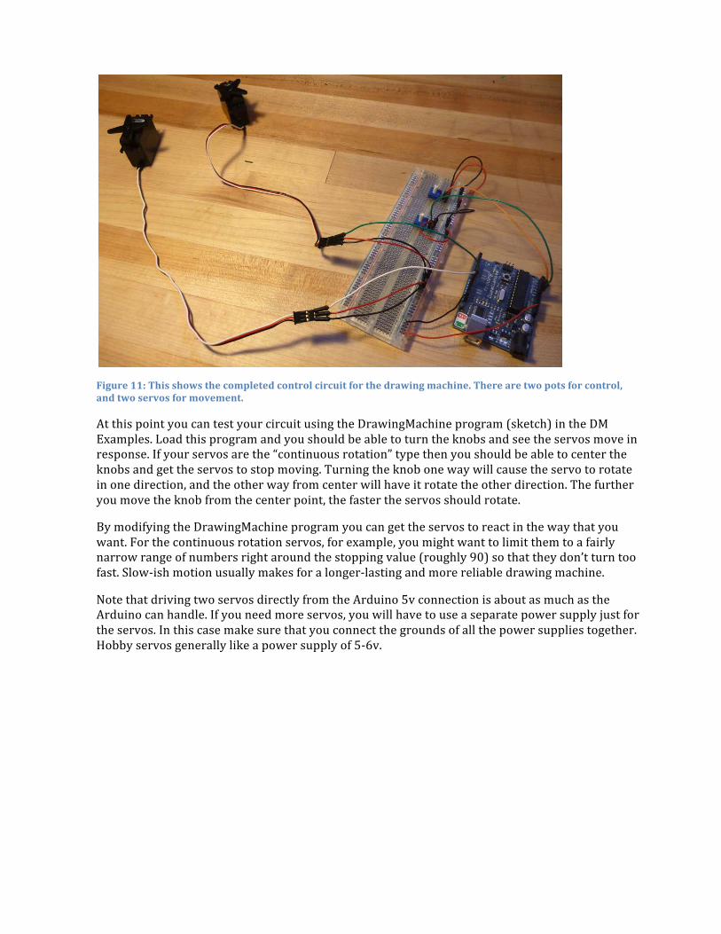
Figure 11: This shows the completed control circuit for the drawing machine. There are two pots for control, and two servos for movement.
At this point you can test your circuit using the DrawingMachine program (sketch) in the DM Examples. Load this program and you should be able to turn the knobs and see the servos move in response. If your servos are the “continuous rotation” type then you should be able to center the knobs and get the servos to stop moving. Turning the knob one way will cause the servo to rotate in one direction, and the other way from center will have it rotate the other direction. The further you move the knob from the center point, the faster the servos should rotate.
By modifying the DrawingMachine program you can get the servos to react in the way that you want. For the continuous rotation servos, for example, you might want to limit them to a fairly narrow range of numbers right around the stopping value (roughly 90) so that they don’t turn too fast. Slow-‐ish motion usually makes for a longer-‐lasting and more reliable drawing machine.
Note that driving two servos directly from the Arduino 5v connection is about as much as the Arduino can handle. If you need more servos, you will have to use a separate power supply just for the servos. In this case make sure that you connect the grounds of all the power supplies together. Hobby servos generally like a power supply of 5-‐6v.

DrawingMachine Arduino program – Here’s a program you can start with to get your drawing machine moving. It will take the input from two pots and use the knob postions on those pots to control the servos.
/* * This program is the control for a two-servo drawing * machine. This machine uses two pots (or other resistive sensors) * to control two servos. The two servos make the arms of the * drawing machine move, and thus make drawings. * * You could make this machine reactive to the environment by * replacing the pots with other environmental resistive sensors * such as light sensors, heat sensors, etc. This assumes that you * install the resistive sensors in a voltage divider arrangement * with the center tap of the voltage divider feeding the analog inputs. * You might also want to calibrate your sensors and adjust the * range using "map" and "constrain" to get full range of motion * of the servos given the range of environmental data you'll be * seeing. */
#include <Servo.h> // include the Servo library Servo servo1, servo2; // create objects for both servos int servo1Pin = 10; // define where the servos are connected int servo2Pin = 9; // choose any digital pins you like
int pot1Pin = A0; // analog pin for first pot/sensor int pot2Pin = A1; // analog pin for second pot/sensor int pot1Val, pot2Val; // variables for pot values
void setup() { servo1.attach(servo1Pin); // attach the servo objects to digital pins servo2.attach(servo2Pin); }
void loop() { pot1Val = analogRead(pot1Pin); // read pot1 value pot2Val = analogRead(pot2Pin); // read pot2 value
// map the values received on the analog inputs from the pots // to the servo's range of motion. If you're using different // analog sensors, here's where you adjust the map function. You // might also want to add a constrain function to make sure you're // keeping the values you're writing to the servos in the // range of 0-179, or in a narrow range to keep the movement slow. pot1Val = map(pot1Val, 0, 1023, 0, 179); pot2Val = map(pot2Val, 0, 1023, 0, 179);
// send the data to the servos servo1.write(pot1Val); servo2.write(pot2Val);
delay(30); // give the servos time to react... }
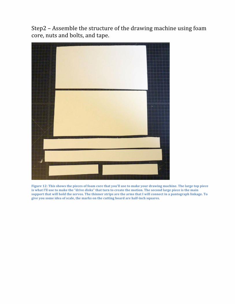
Step2 – Assemble the structure of the drawing machine using foam core, nuts and bolts, and tape.
Figure 12: This shows the pieces of foam core that you'll use to make your drawing machine. The large top piece is what I’ll use to make the “drive disks” that turn to create the motion. The second large piece is the main support that will hold the servos. The thinner strips are the arms that I will connect in a pantograph linkage. To give you some idea of scale, the marks on the cutting board are half-‐inch squares.
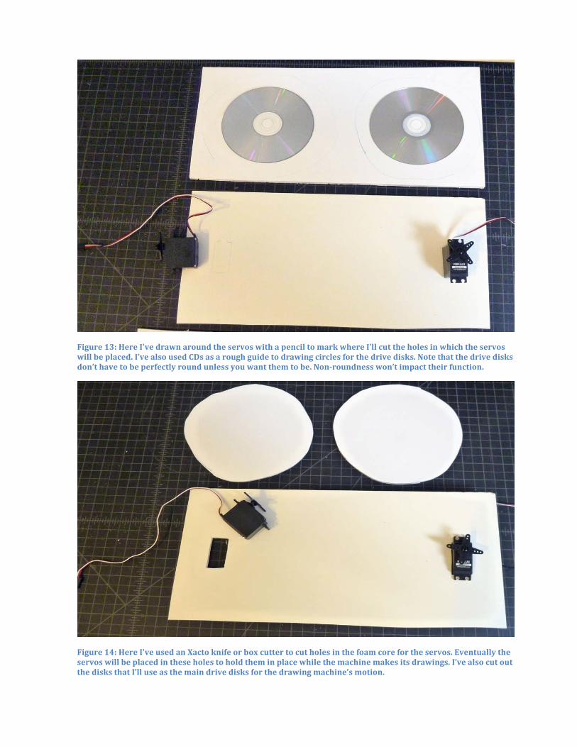
Figure 13: Here I've drawn around the servos with a pencil to mark where I'll cut the holes in which the servos will be placed. I’ve also used CDs as a rough guide to drawing circles for the drive disks. Note that the drive disks don’t have to be perfectly round unless you want them to be. Non-‐roundness won’t impact their function.
Figure 14: Here I've used an Xacto knife or box cutter to cut holes in the foam core for the servos. Eventually the servos will be placed in these holes to hold them in place while the machine makes its drawings. I’ve also cut out the disks that I’ll use as the main drive disks for the drawing machine’s motion.

Figure 15: The first step in the assembly of the drive disks is to poke holes in the disks that will be used to connect the pantograph arms. I’ve used a 6-‐32 bolt and just punched through the foam core. You can also use something pointy like a pencil or pen. I’ve also made some spacers out of some foam core scraps that might or might not be useful later. If the pantograph arms are rubbing on the drive disks it’s sometimes useful to offset the arms from the disks with a spacer like this. It’s not always necessary though.
Figure 16: Now I'm attaching the servo to the drive disk. The servos have a “horn” installed. This is the plastic piece with four arms that rotates when the servo is told to rotate. I’ve just used masking tape to connect the servo horn to the drive disk.
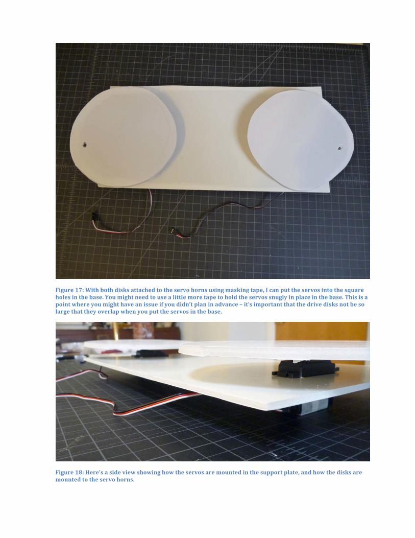
Figure 17: With both disks attached to the servo horns using masking tape, I can put the servos into the square holes in the base. You might need to use a little more tape to hold the servos snugly in place in the base. This is a point where you might have an issue if you didn’t plan in advance – it’s important that the drive disks not be so large that they overlap when you put the servos in the base.
Figure 18: Here's a side view showing how the servos are mounted in the support plate, and how the disks are mounted to the servo horns.
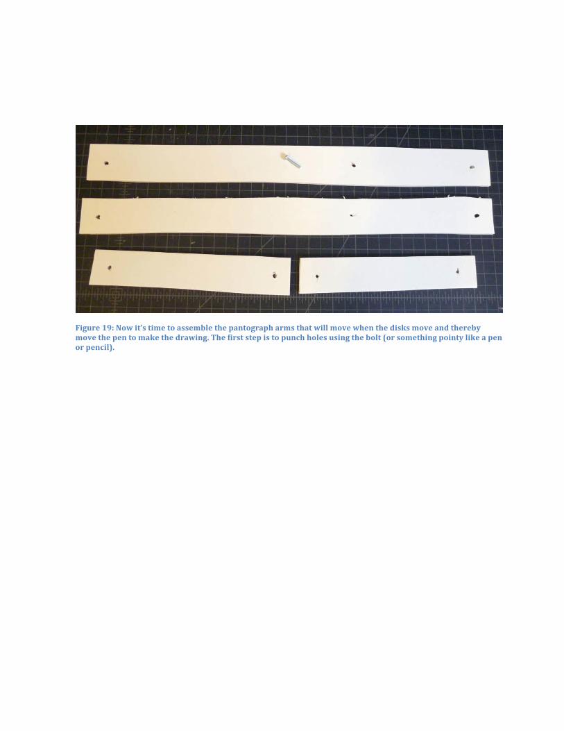
Figure 19: Now it’s time to assemble the pantograph arms that will move when the disks move and thereby move the pen to make the drawing. The first step is to punch holes using the bolt (or something pointy like a pen or pencil).
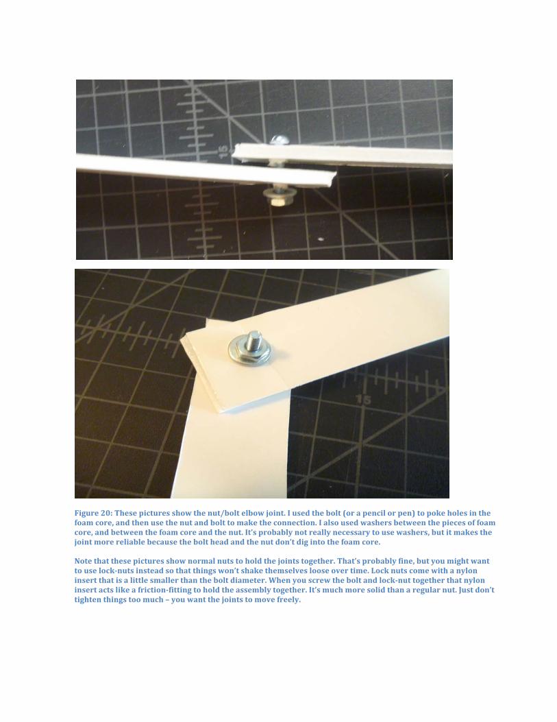
Figure 20: These pictures show the nut/bolt elbow joint. I used the bolt (or a pencil or pen) to poke holes in the foam core, and then use the nut and bolt to make the connection. I also used washers between the pieces of foam core, and between the foam core and the nut. It’s probably not really necessary to use washers, but it makes the joint more reliable because the bolt head and the nut don’t dig into the foam core. Note that these pictures show normal nuts to hold the joints together. That’s probably fine, but you might want to use lock-‐nuts instead so that things won’t shake themselves loose over time. Lock nuts come with a nylon insert that is a little smaller than the bolt diameter. When you screw the bolt and lock-‐nut together that nylon insert acts like a friction-‐fitting to hold the assembly together. It’s much more solid than a regular nut. Just don’t tighten things too much – you want the joints to move freely.
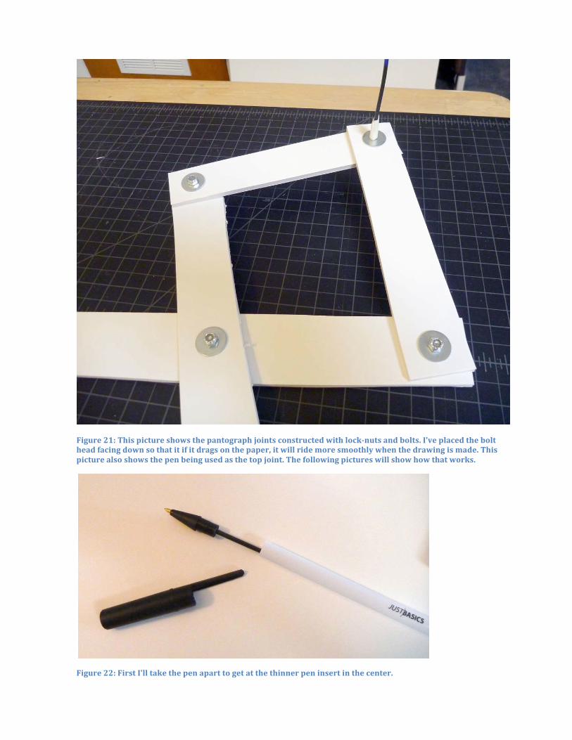
Figure 21: This picture shows the pantograph joints constructed with lock-‐nuts and bolts. I’ve placed the bolt head facing down so that it if it drags on the paper, it will ride more smoothly when the drawing is made. This picture also shows the pen being used as the top joint. The following pictures will show how that works.
Figure 22: First I'll take the pen apart to get at the thinner pen insert in the center.
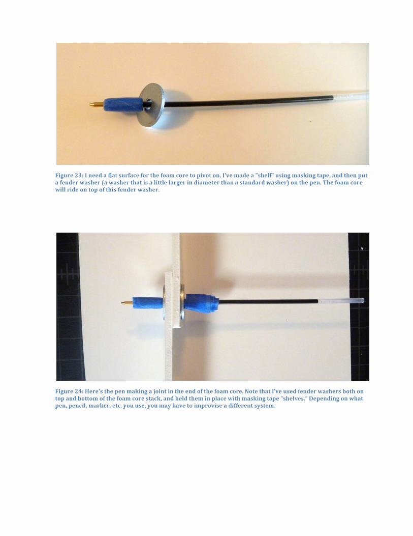
Figure 23: I need a flat surface for the foam core to pivot on. I've made a "shelf" using masking tape, and then put a fender washer (a washer that is a little larger in diameter than a standard washer) on the pen. The foam core will ride on top of this fender washer.
Figure 24: Here's the pen making a joint in the end of the foam core. Note that I’ve used fender washers both on top and bottom of the foam core stack, and held them in place with masking tape “shelves.” Depending on what pen, pencil, marker, etc. you use, you may have to improvise a different system.
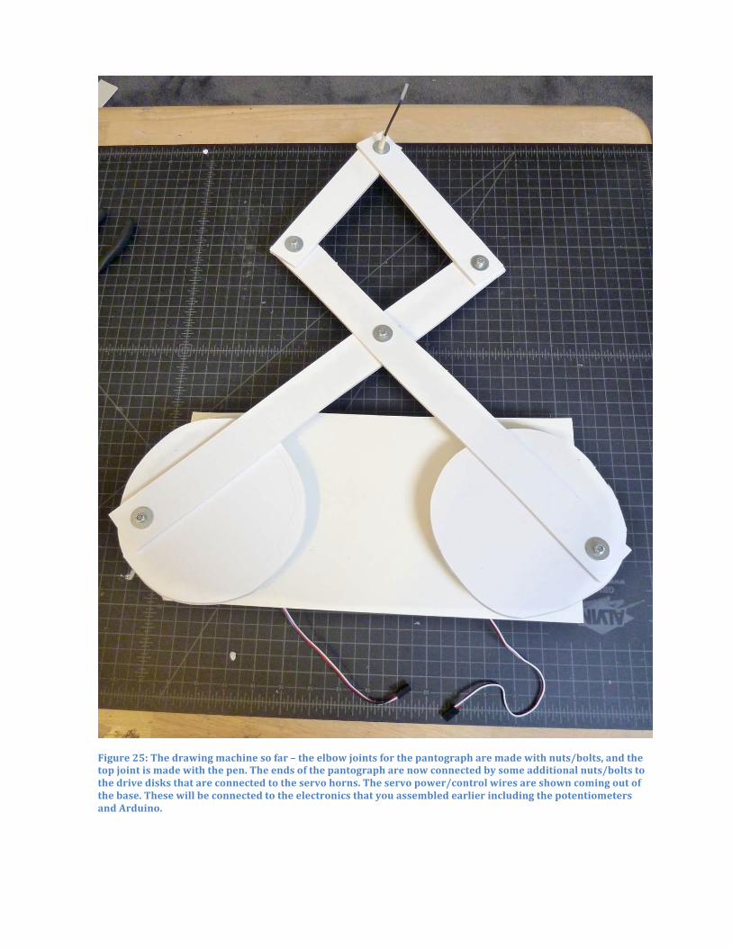
Figure 25: The drawing machine so far – the elbow joints for the pantograph are made with nuts/bolts, and the top joint is made with the pen. The ends of the pantograph are now connected by some additional nuts/bolts to the drive disks that are connected to the servo horns. The servo power/control wires are shown coming out of the base. These will be connected to the electronics that you assembled earlier including the potentiometers and Arduino.
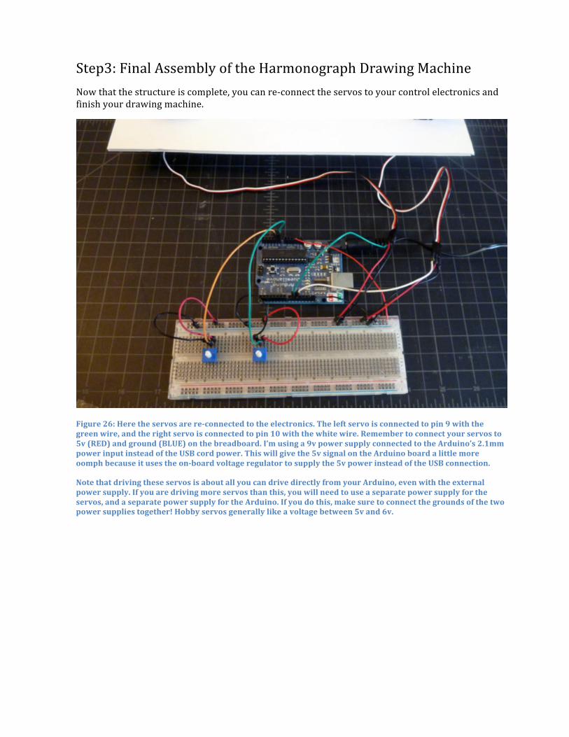
Step3: Final Assembly of the Harmonograph Drawing Machine Now that the structure is complete, you can re-‐connect the servos to your control electronics and finish your drawing machine.
Figure 26: Here the servos are re-‐connected to the electronics. The left servo is connected to pin 9 with the green wire, and the right servo is connected to pin 10 with the white wire. Remember to connect your servos to 5v (RED) and ground (BLUE) on the breadboard. I’m using a 9v power supply connected to the Arduino’s 2.1mm power input instead of the USB cord power. This will give the 5v signal on the Arduino board a little more oomph because it uses the on-‐board voltage regulator to supply the 5v power instead of the USB connection.
Note that driving these servos is about all you can drive directly from your Arduino, even with the external power supply. If you are driving more servos than this, you will need to use a separate power supply for the servos, and a separate power supply for the Arduino. If you do this, make sure to connect the grounds of the two power supplies together! Hobby servos generally like a voltage between 5v and 6v.

Figure 27: Here’s the finished harmonograph Drawing Machine. You can make drawings by turning the knobs on the potentiometers. You might have to add weight to the pen to make nice dark lines. Large washers make great weights – you can just place them over the pen’s joint as you can see if you look closely to this picture.
There are many ways you can customize your drawing machine. One would be to use different sensors other than pots. For example, if you replaced the pots with some environmental sensor such as a light sensor, your machine would draw based on environmental conditions instead of direct control by a person. You could also write a program to directly control the servos using a drawing algorithm, or random function, or both. There are also many different mechanical linkages you might consider other than this simple four-‐arm linkage. There are a huge number of possibilities!

This drawing machine is a simple project, but one that demonstrates a large number of physical computing concepts. These are just a few of those concepts:
• The project demonstrates the control of physical movement by a program. The program sends signals to the servos using pulse width modulation to tell the servos what angular position they should assume or how fast to rotate. The Arduino Servo.h library handles the details, but the basic concept is that by driving signals to a digital output pin your program can cause things to move physically.
• The pots are a good example of external sensors providing information to a program. Programs need inputs to provide data to be processed. In this case the inputs are real-‐time environmental inputs that are sampled by the program.
• The environmental condition being sensed here is the position of the knob, but this extends naturally to a wide range of environmental sensors, especially so-‐called “resistive sensors.” These are sensors that change their resistance in response to environmental conditions such as light, heat, movement, distance, etc.
• This project involves simple electronics concepts such as power and ground being required for electronic and electromechanical components. As a side note it can bring up topics such as power and current limits, and using multiple power supplies.
• The controller introduces the “solderless breadboard” as a prototyping substrate for electronics. These breadboards are commonly used to quickly assemble electronics for testing or debugging. By poking wires in the breadboards, electrical connections can be made and modified quickly and easily.
• The control program running on the Arduino demonstrates a “reactive programming” approach to algorithm design. The “loop” program in the Arduino programming environment (previous page) is an endless loop. Each time through the loop the environmental sensors (pots) are sampled to get their new values. Those values are interpolated (mapped) to the desired range, and then used to control the position of the servos. Each time through the loop, the control program reacts to the environmental conditions by causing some activity in the outputs.
• This project also demonstrates the strong connection that can exist between technology and the arts. This drawing machine will not make masterpieces, but it does demonstrate the basic concepts of how physical computing can be used to create kinetic sculptures. Imagine a more complex drawing machine, or a room full of simple drawing machines reacting to environmental conditions. That could be a really compelling art piece. This can help CS students see a very different application domain for computing, and can also help art students understand the possibilities of computer control in their art practice.
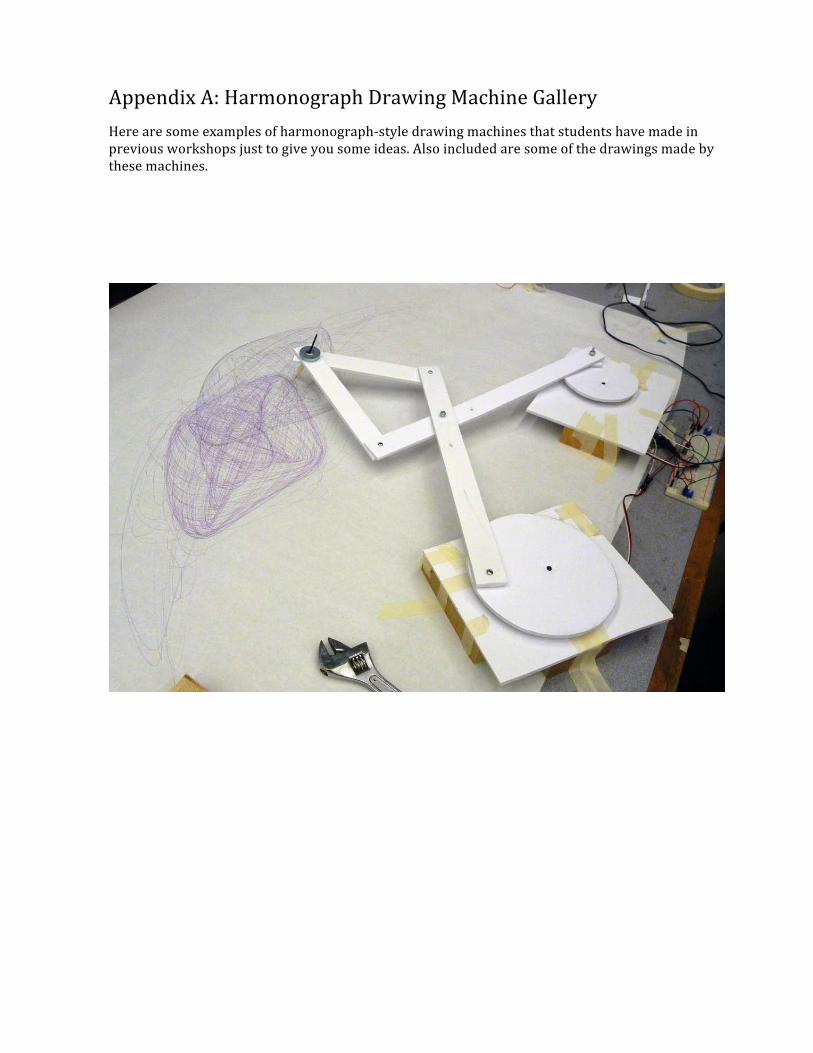
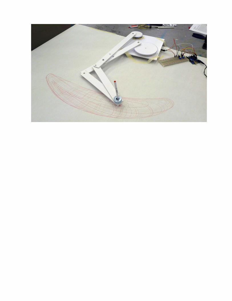
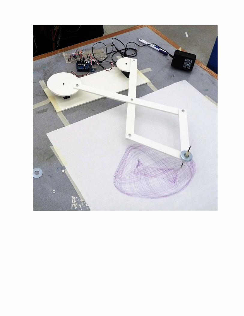
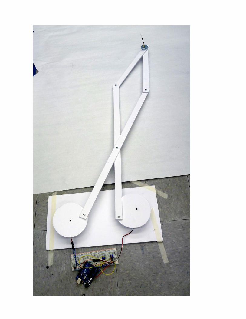
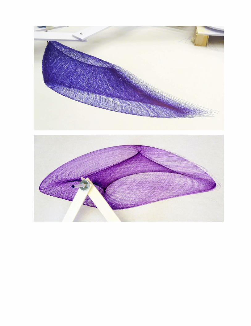
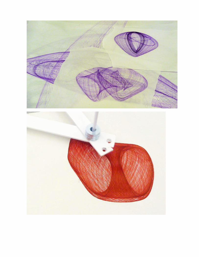
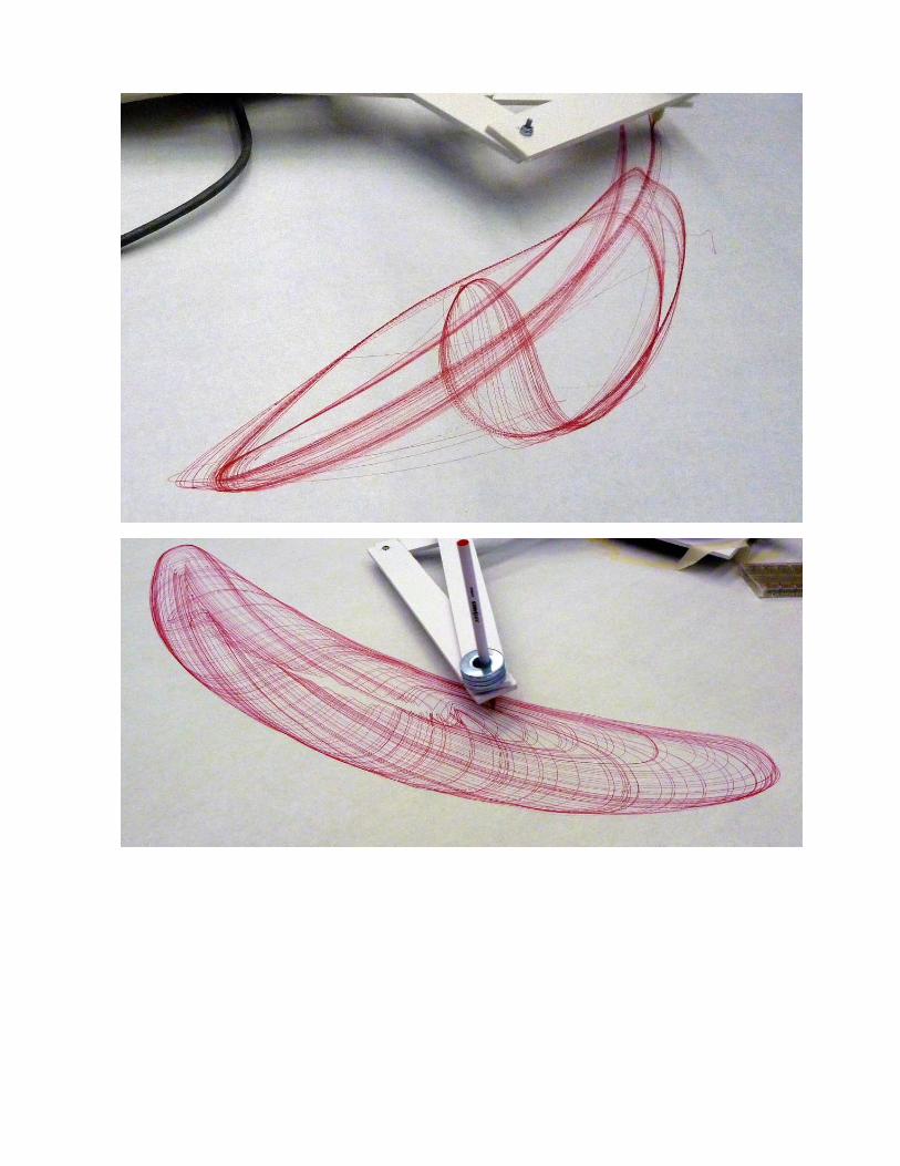
Appendix A: Harmonograph Drawing Machine Gallery Here are some examples of harmonograph-‐style drawing machines that students have made in previous workshops just to give you some ideas. Also included are some of the drawings made by these machines.
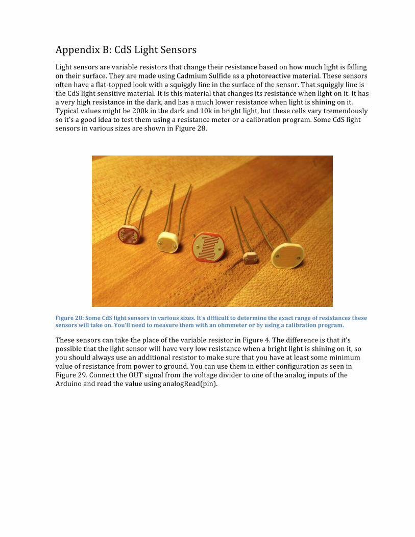
Appendix B: CdS Light Sensors Light sensors are variable resistors that change their resistance based on how much light is falling on their surface. They are made using Cadmium Sulfide as a photoreactive material. These sensors often have a flat-‐topped look with a squiggly line in the surface of the sensor. That squiggly line is the CdS light sensitive material. It is this material that changes its resistance when light on it. It has a very high resistance in the dark, and has a much lower resistance when light is shining on it. Typical values might be 200k in the dark and 10k in bright light, but these cells vary tremendously so it’s a good idea to test them using a resistance meter or a calibration program. Some CdS light sensors in various sizes are shown in Figure 28.
Figure 28: Some CdS light sensors in various sizes. It’s difficult to determine the exact range of resistances these sensors will take on. You’ll need to measure them with an ohmmeter or by using a calibration program.
These sensors can take the place of the variable resistor in Figure 4. The difference is that it’s possible that the light sensor will have very low resistance when a bright light is shining on it, so you should always use an additional resistor to make sure that you have at least some minimum value of resistance from power to ground. You can use them in either configuration as seen in Figure 29. Connect the OUT signal from the voltage divider to one of the analog inputs of the Arduino and read the value using analogRead(pin).
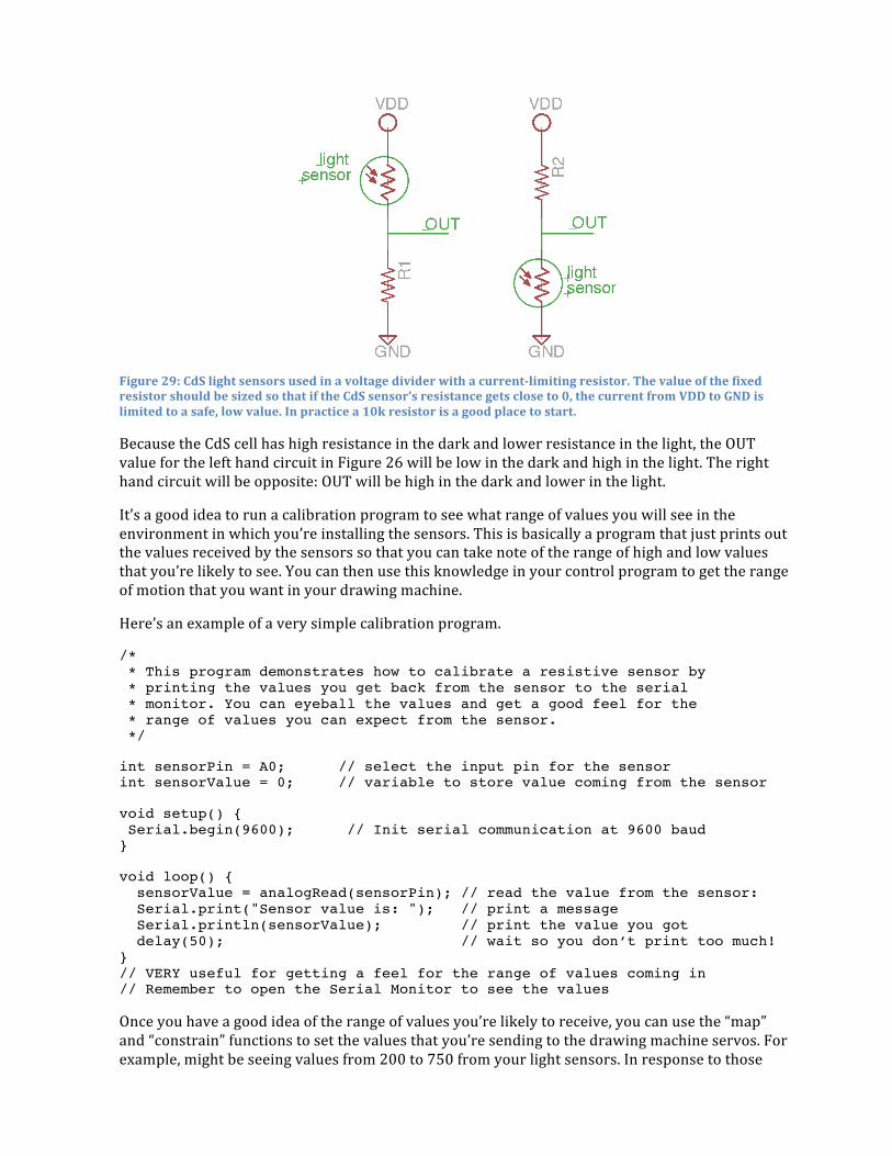
Figure 29: CdS light sensors used in a voltage divider with a current-‐limiting resistor. The value of the fixed resistor should be sized so that if the CdS sensor’s resistance gets close to 0, the current from VDD to GND is limited to a safe, low value. In practice a 10k resistor is a good place to start.
Because the CdS cell has high resistance in the dark and lower resistance in the light, the OUT value for the left hand circuit in Figure 26 will be low in the dark and high in the light. The right hand circuit will be opposite: OUT will be high in the dark and lower in the light.
It’s a good idea to run a calibration program to see what range of values you will see in the environment in which you’re installing the sensors. This is basically a program that just prints out the values received by the sensors so that you can take note of the range of high and low values that you’re likely to see. You can then use this knowledge in your control program to get the range of motion that you want in your drawing machine.
Here’s an example of a very simple calibration program.
/* * This program demonstrates how to calibrate a resistive sensor by * printing the values you get back from the sensor to the serial * monitor. You can eyeball the values and get a good feel for the * range of values you can expect from the sensor. */
int sensorPin = A0; // select the input pin for the sensor int sensorValue = 0; // variable to store value coming from the sensor
void setup() { Serial.begin(9600); // Init serial communication at 9600 baud }
void loop() { sensorValue = analogRead(sensorPin); // read the value from the sensor: Serial.print("Sensor value is: "); // print a message Serial.println(sensorValue); // print the value you got delay(50); // wait so you don’t print too much! } // VERY useful for getting a feel for the range of values coming in // Remember to open the Serial Monitor to see the values
Once you have a good idea of the range of values you’re likely to receive, you can use the “map” and “constrain” functions to set the values that you’re sending to the drawing machine servos. For example, might be seeing values from 200 to 750 from your light sensors. In response to those
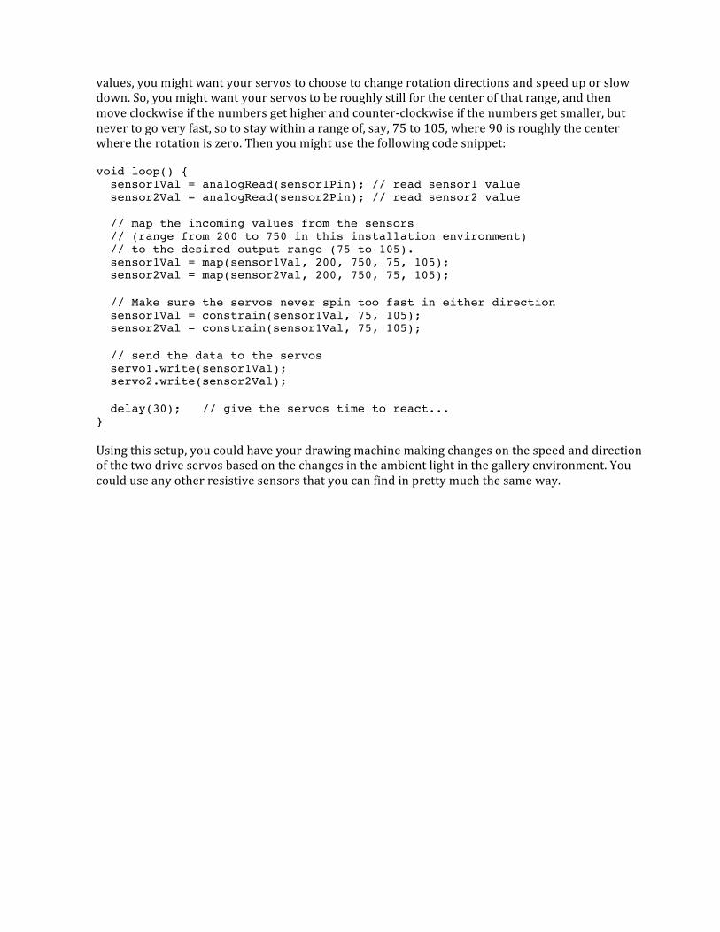
values, you might want your servos to choose to change rotation directions and speed up or slow down. So, you might want your servos to be roughly still for the center of that range, and then move clockwise if the numbers get higher and counter-‐clockwise if the numbers get smaller, but never to go very fast, so to stay within a range of, say, 75 to 105, where 90 is roughly the center where the rotation is zero. Then you might use the following code snippet:
void loop() { sensor1Val = analogRead(sensor1Pin); // read sensor1 value sensor2Val = analogRead(sensor2Pin); // read sensor2 value // map the incoming values from the sensors // (range from 200 to 750 in this installation environment) // to the desired output range (75 to 105). sensor1Val = map(sensor1Val, 200, 750, 75, 105); sensor2Val = map(sensor2Val, 200, 750, 75, 105);
// Make sure the servos never spin too fast in either direction sensor1Val = constrain(sensor1Val, 75, 105); sensor2Val = constrain(sensor1Val, 75, 105);
// send the data to the servos servo1.write(sensor1Val); servo2.write(sensor2Val);
delay(30); // give the servos time to react... }
Using this setup, you could have your drawing machine making changes on the speed and direction of the two drive servos based on the changes in the ambient light in the gallery environment. You could use any other resistive sensors that you can find in pretty much the same way.
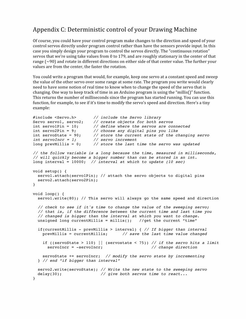
Appendix C: Deterministic control of your Drawing Machine Of course, you could have your control program make changes to the direction and speed of your control servos directly under program control rather than have the sensors provide input. In this case you simply design your program to control the servos directly. The “continuous rotation” servos that we’re using take values from 0 to 179, and are roughly stationary in the center of that range (~90) and rotate in different directions on either side of that center value. The further your values are from the center, the faster the rotation.
You could write a program that would, for example, keep one servo at a constant speed and sweep the value of the other servo over some range at some rate. The program you write would clearly need to have some notion of real time to know when to change the speed of the servo that is changing. One way to keep track of time in an Arduino program is using the “millis()” function. This returns the number of milliseconds since the program has started running. You can use this function, for example, to see if it’s time to modify the servo’s speed and direction. Here’s a tiny example:
#include <Servo.h> // include the Servo library Servo servo1, servo2; // create objects for both servos int servo1Pin = 10; // define where the servos are connected int servo2Pin = 9; // choose any digital pins you like int servoState = 90; // store the current state of the changing servo int servoIncr = 1; // servo increment long prevMillis = 0; // store the last time the servo was updated // the follow variable is a long because the time, measured in milliseconds, // will quickly become a bigger number than can be stored in an int. long interval = 10000; // interval at which to update (10 sec)
void setup() { servo1.attach(servo1Pin); // attach the servo objects to digital pins servo2.attach(servo2Pin); }
void loop() { servo1.write(80); // This servo will always go the same speed and direction // check to see if it's time to change the value of the sweeping servo; // that is, if the difference between the current time and last time you // changed is bigger than the interval at which you want to change. unsigned long currentMillis = millis(); //get the current “time” if(currentMillis - prevMillis > interval) { // If bigger than interval prevMillis = currentMillis; // save the last time value changed if ((servoState > 110) || (servostate < 75)) // if the servo hits a limit servoIncr = -servoIncr; // change direction servoState += servoIncr; // modify the servo state by incrementing } // end “if bigger than interval” servo2.write(servoState); // Write the new state to the sweeping servo delay(30); // give both servos time to react... }

Appendix D: Sources for Supplies This is a definitely non-‐exhaustive list of some of the equipment mentioned in this course, a rough guide to prices, and some example suppliers.
Arduino: The main site for the Arduino is www.arduino.cc. This is the official site for all open-‐source Arduino information, and for software downloads. A great secondary source for Arduino is www.freeduino.org which is a non-‐official community-‐supported site.
Arduino comes in many hardware variations. The current generic Arduino is the Arduino Uno. It retails for around $30. Some suppliers include:
• Sparkfun: www.sparkfun.com • Radio Shack: www.radioshack.com • Adafruit: www.adafruit.com • Hacktronics: www.hacktronics.com
These are also great sources for all sorts of things related to embedded systems, physical computing, making, and hardware hacking.
Switches and sensors: The previously mentioned sources also have loads of switches and sensors of all sorts. Many of the sensors that we didn’t discuss in this workshop are also resistive sensors and can be used in exactly the same way as we used pots and light sensors.
Other sources for small electronic parts like this include:
• Jameco: www.jameco.com • Digikey: www.digikey.com • Mouser: www.mouser.com
Of these suppliers, Jameco is more for the hobbyist, and Digikey and Mouser are more for the professional. They all sometimes have great prices, especially in quantity, but you sometimes really have to know what you’re looking for. As an example an individual light sensor at Sparkfun or Jameco runs between $1.25 and $2.00. But, with a little more searching, Jameco has a bag of 50 assorted light sensors for $15. Look also for Jameco’s bags of assorted switches, assorted LEDs, etc. They can be a great way to quickly stock a set of kits.
Servos: These are the type of servos used in radio controlled model airplanes and model cars, and for small robotics projects. So, any hobby shop will have them. Radio Shack, Sparkfun, etc. also carry them, but you might find a better deal at a hobby shop or a robotics hobbyist shop. Some examples:
• Hobby Partz: www.hobbypartz.com • Servo City: www.servocity.com • Trossen Robotics: www.trossenrobotics.com • Pololu: www.pololu.com

Electronics surplus resellers: Sometimes you can find great deals on surplus parts at a surplus reseller. Here you really do need to know exactly what you’re getting, and be willing to take some chances, but you can find some real bargains if you look around.
Some examples:
• Electronics Goldmine: www.goldmine-‐elec.com • Marlin P. Jones: www.mpja.com/ • Alltronics: www.alltronics.com/ • Electronics Surplus: www.electronicsurplus.com/
Lady Ada (Limor Fried) at Adafruit also has some great suggestions at: www.ladyada.net/library/procure/hobbyist.html