arcsa/aspe 63: rainwater catchment...
TRANSCRIPT

ARCSA/ASPE 63: Rainwater Catchment Systems First Public Review (December 2012) This draft has been recommended for public review by the ASPE Main Design Standards Committee. To submit a comment on this proposed standard, go to the ASPE website at aspe.org/PublicReview to access the comment form. © 2012 American Rainwater Catchment System Association and American Society of Plumbing Engineers. All Rights Reserved. Permission to reproduce or redistribute all or any part of this document must be obtained from the ASPE Director of Standards at [email protected].

ARCSA-ASPE_63_Draft3_Approved_for_public_review.docx
2
Forward (Informative)
This Rainwater Catchment Design and Installation Standard (hereinafter referred to as the Standard) has been developed by a joint effort of the American Rainwater Catchment Systems Association (ARCSA) and the American Society of Plumbing Engineers (ASPE), with sponsorship support from the International Association of Plumbing and Mechanical Officials. The purpose of this Standard is to assist engineers, designers, plumbers, builders/developers, local government, and end users in safely implementing a rainwater catchment system. This Standard is intended to apply to new rainwater catchment installations, as well as alterations, additions, maintenance, and repairs to existing installations. This Standard is intended to be consistent with, and complimentary to, nationally adopted codes and regulations. However, designers/installers are advised to consult with the plumbing authority having jurisdiction regarding local conditions, requirements, and restrictions.

ARCSA-ASPE_63_Draft3_Approved_for_public_review.docx
3
The Standard (Normative)
1.0 SCOPE
The scope of this Standard covers rainwater catchment systems that utilize the principle of collecting and using precipitation from a rooftop and other hard, impervious surfaces. This Standard does not apply to the collection of rainwater from vehicular parking or other similar surfaces.
1.1 PERFORMANCE OBJECTIVES
1.1.1 The objectives of this Standard are to provide guidance in how to provide and maintain a healthy alternative to utility-provided water, and to optimize rainwater utilization, while ensuring:
a. Reduction of risk to consumers from poor design, installation, maintenance, or
illegal work.
b. Reduction of risk to the public from injury or loss of amenity due to a failure of the supply, installation, maintenance, or operation of the rainwater catchment system.
c. The rainwater catchment system will assist in maintaining and enhancing the
quality of the environment while helping to ensure compliance with the intent of relevant regulations and government officials.
1.2 UNITS OF MEASUREMENT
1.2.1 Values are stated in metric or the International System of Units (SI) with U.S. Customary Units being referenced parenthetically. The SI units shall be considered as the standard.
2.0 REFERENCED STANDARDS
The standards referenced in this section are considered normative either by direct reference in this Standard or through a general reference of this Section in the Standard:1
2.1 American Society of Mechanical Engineers (ASME) ASME A 112.6.4-2003: Roof, Deck and Balcony Drains 2.2 American Public Health Association, American Water Works Association, Water Environment
Federation Standard Methods for the Examination of Water and Wastewater, 22nd Edition
1 Additional standard and guidance document references have been provided in Annex A for informational purposes.
ARCSA-ASPE_63_Draft3_Approved_for_public_review.docx
4
2.3 ASTM International ASTM B32-08: Standard Specification for Solder Metal ASTM B75/B75M-11: Standard Specifications for Seamless Copper Tube
ASTM B828-02 (2010): Standard Practice for Making Capillary Joints by Soldering of Copper and Copper Alloy Tube and Fittings
ASTM D1785-12: Standard Specification for Poly(Vinyl Chloride) (PVC) Plastic Pipe, Schedules 40, 80, and 120
ASTM D2241-09: Standard Specification for Poly(Vinyl Chloride) (PVC) Pressure Rated Pipe (SDR Series)
ASTM D2466-06: Standard Specification for Poly(Vinyl Chloride) (PVC) Plastic Pipe Fittings, Schedule 40
ASTM D2467-06: Standard Specification for Poly(Vinyl Chloride) (PVC) Plastic Pipe Fittings, Schedule 80
ASTM D2657-07: Standard Practice for Heat Fusion Joining of Polyolefin Pipe and Fittings
ASTM D2661-11: Standard Specification for Acrylonitrile-Butadiene-Styrene (ABS) Schedule 40 Plastic Drain, Waste, and Vent Pipe and Fittings
ASTM D2665-12: Standard Specification for Poly(Vinyl Chloride) (PVC) Plastic Drain, Waste, and Vent Pipe and Fittings
ASTM D2855-96 (2010): Standard Practice for Making Solvent-Cemented Joints with Poly(Vinyl Chloride) (PVC) Pipe and Fittings
ASTM D2949-10: Standard Specification for 3.25-in. Outside Diameter Poly(Vinyl Chloride) (PVC) Plastic Drain, Waste, and Vent Pipe and Fittings
ASTM D3261-10a: Standard Specification for Butt Heat Fusion Polyethylene (PE) Plastic Fittings for Polyethylene (PE) Plastic Pipe and Tubing
ASTM D3311-11: Standard Specification for Drain, Waste, and Vent (DWV) Plastic Fittings Patterns
ASTM D3350-12: Standard Specification for Polyethylene Plastics Pipe and Fittings Materials
ASTM F628-08: Standard Specification for Acrylonitrile-Butadiene-Styrene (ABS) Schedule 40 Plastic Drain, Waste, and Vent Pipe With a Cellular Core
ASTM F714-12e1: Standard Specification for Polyethylene (PE) Plastic Pipe (DR-PR) Based on Outside Diameter
ASTM F1866-07: Standard Specification for Poly(Vinyl Chloride) (PVC) Plastic Schedule 40 Drainage and DWV Fabricated Fittings

ARCSA-ASPE_63_Draft3_Approved_for_public_review.docx
5
ASTM F1901-10: Standard Specification for Polyethylene (PE) Pipe and Fittings for Roof Drain Systems
2.4 American Water Works Association (AWWA)
ANSI/AWWA C110/A21.10-2012: Standard for Ductile-Iron and Gray-Iron Fittings AWWA C606-2011: Standard for Grooved and Shoulder Joints 2.5 Cast Iron Soil Pipe Institute (CISPI)
CISPI 301-09: Standard Specification for Hubless Cast Iron Soil Pipe and Fittings for Sanitary and Storm Drain, Waste and Vent Piping Applications
CISPI 310-11: Standard Specification for Couplings for Use in Connection With Hubless Cast Iron Soil Pipe and Fittings for Sanitary and Storm Drain, Waste, and Vent Piping Applications
2.6 International Organization for Standardization (ISO)
ISO/IEC 17065-2012: Conformity Assessment -- Requirements for Bodies Certifying Products, Processes and Services ISO/IEC 17011-2004: Conformity Assessment -- General Requirements for Accreditation Bodies Accrediting Conformity Assessment Bodies
2.7 NSF International
NSF Protocol P151: Health Effects from Rainwater Catchment System Components
NSF/ANSI Standard 14-2011: Plastic Piping System Components and Related Materials NSF/ANSI Standard 42-2010: Drinking Water Treatment Units -- Aesthetic Effects
NSF/ANSI Standard 53-2010: Drinking Water Treatment Units -- Health Effects
NSF/ANSI Standard 55-2009: Ultraviolet Microbiological Water Treatment Systems
NSF/ANSI Standard 58-2009: Reverse Osmosis Drinking Water Treatment Systems
NSF/ANSI Standard 60-2011: Drinking Water Treatment Chemicals -- Health Effects NSF/ANSI Standard 61-2011: Drinking Water System Components -- Health Effects 2.8 U.S. Department of Labor – Occupational Safety & Health Administration (OSHA) Standard 1926: Safety and Health Regulations for Construction, Subpart P, Excavations

ARCSA-ASPE_63_Draft3_Approved_for_public_review.docx
6
3.0 DESIGN AND INSTALLATION REQUIREMENTS
3.1 Collection Parameters
3.1.1 All piping and plumbing system materials and components used in the installation of a rainwater catchment system shall comply with the applicable referenced standards specified in Section 2 and be approved for the specific use per local plumbing code, or be listed by an accredited certification body as available.
a. Collection roofing, gutters, piping, fittings, valves, screens, downspouts, leaders,
flushing devices, tanks, and liners shall be approved for the intended use. b. All tank interior surfaces and equipment shall be washed clean before they are
put into service. c. For water storage volumes totaling less than 1,363 liters (360 gallons), or
intended for minor utility, irrigation, and garden use, no treatment is required. d. Water level control devices that control pumps, makeup water valves, etc., in
contact with the water supply shall be mercury-free devices. e. The system shall be located and maintained to minimize or prevent overhanging
vegetation and airborne pollution from contaminating collected rainwater.
3.1.2 For nonpotable water applications,
a. The collection surface shall be constructed of aboveground, hard surface, impervious material.
b. Harvested rainwater shall be filtered or treated to an appropriate quality suitable
for intended use. No treatment is required for subsurface irrigation or agricultural use. For above-surface irrigation, the local authority having jurisdiction should be consulted regarding required water quality.
3.2 Conveyance System
3.2.1 The roof drainage system or gutters and downspouts used to collect rainwater shall
comply with the following: a. All piping, plumbing components, and material used shall be manufactured of
material approved for the intended application, conforming to the standards described herein in Section 2.
b. Gutter and downspout systems leading to the cistern shall be fitted with a debris
excluder or equivalent device. 3.3 Pre-filtration 3.3.1 All collected rainwater shall pass through a pre-filtration system before the rainwater
enters the cistern(s).

ARCSA-ASPE_63_Draft3_Approved_for_public_review.docx
7
a. The inlet to the pre-filter shall be provided with a debris screen that protects the cistern from the intrusion of debris, vectors, and vermin. The debris screen shall be corrosion resistant and shall have openings no larger than a nominal 0.15 cm (1,500 microns) (1/16 in.).
Exception: Pre-filters with a self-cleaning design are not required to have the
aforementioned debris screen.
b. If more than one cistern is used, a pre-filtration system shall be provided for each cistern.
Exception: Where cisterns are interconnected to supply water in series, a single
pre filter is permitted c. Pre-filtration screens or filters shall be readily accessible for regular
maintenance and be maintained consistent with manufacturer’s specifications.
3.3.2 First flush devices are optionally used to wash accumulated debris from the collection surface before rainwater is allowed to enter the storage tank. When first flush devices are used, these systems shall meet the following design requirements:
a. First flush devices shall be placed after pre-filtration. b. Approximate amount of rainfall to be diverted shall be adjustable as necessary to
minimize cistern water contamination. (See Annex B, Acceptable Piping Schematics, for guidance in determining pre-wash water volume.)
c. Water drained from the first flush device shall be piped away from the storage
tank and terminate in a location so as not to cause damage to property or cause erosion.
d. First flush devices shall be provided with an automatic means of self-draining
between rain events.
e. First flush devices shall be readily accessible for regular maintenance. 3.4 Cisterns / Storage The following are the minimum requirements for cisterns. Additional requirements are provided
in Section 3.7 for potable water applications.
3.4.1 General
a. Cisterns may be used as rainwater collection points that help to minimize flood damage, while providing a reservoir for later use. All rigid-bodied cisterns and all cisterns over 1.22 m (4 ft) in height (rigid or flexible) shall have access to allow inspection and cleaning.
3.4.2 Installation
a. Cisterns may be installed either above- or below-grade
ARCSA-ASPE_63_Draft3_Approved_for_public_review.docx
8
b. Cisterns shall comply with the administrative authority having jurisdiction, local
building codes and ordinances, and/or as certified by a structural engineer. c. Above-grade plastic tanks used as cisterns shall be certified for the intended
application. d. Above-grade cisterns shall be protected from direct sunlight and shall:
(1) Be constructed using opaque, UV-resistant materials (i.e., heavily tinted
flexible or rigid plastic, metal tank with lining, concrete, etc.). or
(2) Have specially constructed sun barriers (e.g., installed in garages,
crawlspaces, sheds, etc.).
e. Below-grade cisterns, located outside of the building, shall be provided with manhole risers a minimum of 10.2 cm (4 in.) above surrounding grade and/or be installed in such a way as to prevent surface- or groundwater from entering through the top of any fittings. Manholes are to be designed to provide sufficient access into the tank.
f. Where the installation requires a foundation, the foundation shall be flat and shall
be designed to support the cistern’s weight when the cistern is full consistent with the bearing capability of adjacent soil.
g. In areas where sustained freezing temperatures occur, provisions shall be made to keep the cistern and the related piping from freezing.
h. All cisterns shall be installed in accordance with the manufacturer’s installation
instructions.
(1) Underground tanks shall comply with OSHA Standard 1926 Subpart P, fall protection rules and regulations, and any local codes relating to excavation and backfill technique or safety.
(2) Above-grade tanks shall be installed on a sturdy and level foundation or
platform, adequately secured, with adequate drainage consistent with local codes, ordinances, and seismic regulations.
i. In a situation where the soil can become saturated, underground tanks shall be
ballasted, or otherwise secured, to prevent the tank from floating out of the ground when empty. The combined weight of the tank and hold-down ballast shall meet or exceed the buoyancy force of the tank, calculated as follows:
Example (SI): For 3,785.4-liter tank, buoyant force will be 3,785.4 liters x (1 cubic foot/28.32 liters) x 62.4 (0.4536 kg/cubic foot) = 3,783.35 kg.

ARCSA-ASPE_63_Draft3_Approved_for_public_review.docx
9
Buoyancy force of cistern (kg) = 1,000 liters x 28.3 kg/liter = 28,300 kg. If concrete is used for ballast, the volume needed will be: Volume (cubic meters) = 28,300 kg x cubic meters/2,400 kg = 11.8 cubic meters.
Example (U.S.): Buoyant force of cistern (lbs) = Volume (cubic feet) x 62.4 (lbs/cubic foot) For 1,000-gallon tank, buoyant force will be 1,000 gallons x (1 cubic foot/7.48 gallons) x 62.4 (lbs/cubic foot) = 8,342 lbs. If concrete is used as ballast, the volume needed will be: Volume (cubic feet) = 8,342 lbs x cubic feet/150 lbs = 55.6 cubic feet (2.1 cubic yards).
j. Cisterns shall be provided with a means for draining and cleaning. Where gravity
drainage is not possible, provision for pumping water from the tank shall be provided.
k. All cistern openings shall be protected from unintentional entry by humans or
vermin. Manhole covers shall be provided and shall be secured to prevent tampering.
(1) Where an opening is provided that could allow the entry of personnel,
the opening shall be marked, “DANGER -- CONFINED SPACE”
3.4.3 Inlets, Outlets, and Openings
a. Cistern inlets shall be provided to permit water to enter the tank with minimum turbulence.
b. The overflow outlet, or flap valve, shall be protected with a screen having
openings no greater than 0.3 cm (0.125 in.), or as otherwise appropriate, for preventing the entrance of insects or vermin into the cistern.
(1) Overflow outlet shall be sized in accordance with prevailing gutter and
downspout requirements.
(2) Water from the cistern overflow shall be discharged in a manner consistent with local storm water runoff requirements and as approved by the local authority having jurisdiction, or may be allowed to infiltrate excess collected water into the ground.

ARCSA-ASPE_63_Draft3_Approved_for_public_review.docx
10
3.5 PUMP
3.5.1 Where a pump is provided in conjunction with the rainwater harvesting system, the pump shall meet the following provisions:
a. The pump and all other pump components shall be certified and approved for use
with the appropriate potable or nonpotable water systems. b. The pump shall be capable of delivering a minimum of 205 kPa (15 psig)
residual pressure at the highest and /or most remote outlet served. Minimum pump pressure shall allow for friction and other pressure losses. Maximum pressures shall not exceed 653 kPa (80 psig). A pressure-reducing valve shall be provided at water branch distribution piping if the pump is capable of exceeding 618 kPa (75 psig).
3.6 FILTRATION Filtration shall meet the following provisions:
3.6.1 Where rainwater is used for outdoor nonpotable uses and for non-critical operations, such
as irrigation, washdown, etc., a final stage filtration system is not required.
3.6.2 Where rainwater is used for indoor nonpotable use, for laundry, toilets, urinals, process, etc., the water shall be filtered as a safeguard against sediment or discoloration, and for proper operation of valves or other devices.
3.7 PIPING
3.7.1 There shall be no direct connection of any rainwater harvesting pipe system and a public utility-provided domestic potable water pipe system without an approved backflow device.
3.7.2 Separation shall be maintained between potable and nonpotable water systems at all
times. Cross connections, without proper protection in accordance with local applicable plumbing code, shall not be permitted.
a. All material used as part of a rainwater harvesting system shall be certified for
the purpose intended, as designated by the local applicable code.
b. Where rainwater harvesting pipe and potable water pipe are installed in the same trench, wall cavity, or other location, the potable water pipe shall be separated by a minimum distance of 30.5 cm (12 in.) above the rainwater harvesting pipe. Underground pipes shall be installed below the local frost depth.
3.7.3 Piping Materials
a. Rainwater distribution water piping, fittings, and other related system
components shall be suitable for domestic water application as indicated in the applicable local building and/or plumbing code, or as otherwise described in Section 2.

ARCSA-ASPE_63_Draft3_Approved_for_public_review.docx
11
b. Plastic piping shall be protected from UV radiation by a factory-applied protective coating, or painted with a compatible latex paint. Piping and solvent cements shall be approved for the intended use.
3.7.4 Labeling If a rainwater harvesting system is applied to any building, facility, or residence, it shall
be so indicated as follows:
a. All rainwater-supplied fixtures, not specifically treated for potable water use, shall be prominently labeled:
“NONPOTABLE -- DO NOT DRINK”. b. Nonpotable water piping shall be designated by colored bands and solid color
piping as specified by the authority having jurisdiction or national code agencies, and labeled:
“NONPOTABLE -- RAINWATER”. c. Outlets and fixtures served with harvested rainwater shall be easily recognizable
by color or a symbol for nonpotable water.
3.7.5 Inspections Rainwater harvesting systems are considered a private water system under the
responsibility of the building owner/operator, and shall be minimally inspected according to the following schedule:
a. Inspection of all elements before they are covered (rough-in inspection).
b. Final inspection, including testing.
c. In addition to testing required by the code for plumbing systems, the following also apply:
(1) Testing and commissioning.
(2) Piping. A flow test shall be performed through the system to the point of
water distribution and disposal. In addition, the water distribution system shall be tested and proved tight at the operating pressure. Where the manufacturer permits, a 446 kPa (50 psi) hydrostatic test may substitute for the test above. All lines and components shall be watertight.
d. Other inspections as needed to ensure proper system operation.
3.7.6 System Maintenance It is the property owner’s responsibility to maintain the system components according to
manufacturers’ written recommendations.

ARCSA-ASPE_63_Draft3_Approved_for_public_review.docx
12
3.7.7 Rainwater harvesting systems shall be maintained in functioning order for the life of the system.
a. Filtration and disinfection systems shall be serviced in accordance with
manufacturers’ recommendations. b. System Abandonment If the owner of a rainwater harvesting system elects to cease use of, or fails to
properly maintain such system, the owner shall abandon the system. To abandon the system, the system owner shall minimally:
(1) Remove or disable all system connecting piping to utility-provided water
system.
(2) Replace the rainwater harvesting pipe system with an approved potable water supply pipe system. Where an existing potable pipe system is already in place, fixtures may be re-connected to the existing system.
(3) Secure cistern from accidental access by sealing or locking tank inlets and
access points, and/or filling with sand or equivalent. 3.8 POTABLE RAINWATER APPLICATIONS 3.8.1 Collection surfaces for potable water applications shall made of non-toxic material and
meet the requirements noted in 3.1.1 above.
a. Painted surfaces are only acceptable if paint has been certified to ensure the toxicity level of the paint is acceptable for drinking water contact. Lead, chromium or zinc based paints are not permitted.
b. Enameled steel.
c. Flat Roofs: Roof products shall be certified to NSF Protocol P151. d. Collection of water from vehicular parking surfaces is prohibited.
3.8.2 The following materials shall not be used in potable water applications2:
a. Wood /cedar shake roofing.
b. Copper roofing materials.
c. Lead flashing.
2 The use of bitumen/composition roofing or galvanized, zinc-coated metal is not recommended and should be used with caution.

ARCSA-ASPE_63_Draft3_Approved_for_public_review.docx
13
3.8.3 Cisterns
a. Water entering the cistern shall be maintained at a quiescent flow in the cistern by minimizing splashing and disturbance of sediment in bottom of cistern.
b. For potable water applications, and recommended for maintaining good water
quality, the pipe entering the cistern shall terminate in a return bend elbow pointed upward at the bottom of the tank, or equivalent calming device.
c. Cistern outlets shall be provided with floating inlet to draw water from the cistern
just below the water surface, or the outlet shall be located at least 10 cm (4 in.) above the bottom of the cistern.
d. Cisterns shall be certified to NSF/ANSI Standard 61. Plastic tanks shall adhere to
the requirements of NSF/ANSI Standard 61 and be constructed of virgin plastic.
e. Cisterns shall not be connected directly to a public or community water supply without approved backflow protection. Make-up water to rainwater storage tanks, when provided, may be made through a reverse pressure principle backflow device or an air gap per local plumbing codes.
f. If installed below-grade, cisterns shall be separated from sanitary waste piping a
distance as recommended by local authority having jurisdiction or local plumbing codes and up gradient from septic field piping where applicable.
3.8.4 Filtration
a. Carbon filtration may be provided for reduction of taste, odor, and organic
chemicals.
b. Filtration and disinfection systems shall be located after water storage tank and as close to the final point of use as possible.
c. All particulate filtration shall be installed upstream of disinfection systems. d. Filters shall be adequately sized to extend service time and must be comply with
NSF/ANSI Standard 53. 3.8.5 Water Disinfection
a. Chlorination may be used with an automated demand feed system, and if used,
shall enable adequate contact time and residual according to local health authorities.
b. Ozone may be used with an approved ozone system ensuring adequate contact
time with the ozone. Provision must be made to off- gas ozone to a safe environment.
c. Ultraviolet disinfection may be used and shall be provided between final
filtration (5 micron maximum) and final point of use. UV systems shall be certified to NSF/ANSI Standard 55.

ARCSA-ASPE_63_Draft3_Approved_for_public_review.docx
14
3.9 Operation and Maintenance
3.9.1 Prior to Use
Prior to system operation, all debris will be removed from the collection surface and piping system. The cistern and distribution piping shall be cleaned with a sanitizing solution.
a. After several cycles of rainwater harvesting, an initial sample of the resultant
accumulated water shall be tested for compliance according to the procedures listed in the latest edition of Standard Methods for the Examination of Water and Wastewater. Systems that cannot meet the minimum quality standards as listed in Table 3.1 shall be re-cleaned and then tested again, after several additional rain events, for compliance with the applicable standards. Should the water quality still not be achievable, the system shall be provided with an appropriate filtration/disinfection device noted in Sections 3.8.4 and 3.8.5.
b. For private water systems, prior to placing the water system into service, water
quality testing, at a minimum, shall be performed for E. coli, total coliform, and heterotrophic bacteria using the minimum quality standards provided in Table 3.1.
c. Public System
(1) In addition 3.9.1(a) and (b), water shall be tested for Cryptosporidium. (2) Subsequent annual tests shall be made for total coliform, E. coli,
heterotrophic bacteria, and any chemicals of concern.
(3) Records of test results shall be maintained for at least two years.
Table 3.1 STORED RAINWATER MINIMUM QUALITY STANDARDS
PARAMETER
INTENDED END USE QUALITY LEVEL
NONPOTABLE POTABLE 1
Escherichia coli (E. coli) < 100 CFU / 100 ml 99.9999% Reduction
Protozoan Cysts < 10 NTU 99.9% Reduction
Viruses ----------------- 99.99% Reduction
Turbidity < 0.3 NTU
1 Potable water standard meets the United States Environmental Protection Agency (US EPA) drinking water standard for pathogens. Note: Monitoring requirements vary greatly from state to state. Consult state and local guidelines for monitoring requirements.
ARCSA-ASPE_63_Draft3_Approved_for_public_review.docx
15
3.9.2 Water Quality Maintenance
a. The quality of the water for the intended application shall be verified at the point
of use in accordance with the minimum requirements of Table 3.1 complying with the testing procedures set forth in the Standard Methods for the Examination of Water and Wastewater.
b. Nonpotable water shall be tested every 12 months. Potable water shall be tested
every three months. c. For a potable public water system, one sample shall be analyzed for applications
serving up to 1,000 persons. When the treated water shall serve 1,000–2,500 persons, two samples shall be analyzed, and for 2,501 persons and up, three samples shall be analyzed. Samples must come from the following locations when additional taps for sampling are available:
(1) One sample from the same location as the positive sample; (2) One sample within five service connections upstream; (3) One sample within five service connections downstream; and (4) For systems serving 25–1,000 persons, a fourth sample from any other sampling site.
d. If the quality of the tested water cannot consistently be maintained at the
minimum levels specified in Table 3.1, the system shall be equipped with an appropriate treatment device meeting the applicable NSF/ANSI Standard referenced in Section 2.
4.0 DEFINITIONS The following terms are defined in the manner in which they are intended to be used in the Standard. Additional definitions of terms relevant to the scope of this standard that are not used in the body of the Standard are provided in Annex C for informational purposes. 4.1 ACCREDITED: Verification that a certification body meets the requirements of ISO/IEC 17065
by a third-party agency operating in compliance with ISO/IEC 17011. 4.2 CERTIFIED: Verified compliance to a standard by a certification body that has been accredited
by third-party as having systems in compliance with ISO/IEC 17065. 4.3 CISTERN: The central storage component of the rainwater harvesting system. Also referred to as
a storage tank. 4.4 CODE: Refers to the local written authority. 4.5 DEBRIS EXCLUDER: A screen or other device installed on the gutter or downspout system to
prevent the accumulation of leaves, needles, or other debris in the system.
ARCSA-ASPE_63_Draft3_Approved_for_public_review.docx
16
4.6 DISINFECTION: Reduction of viable microorganisms to a level that is deemed suitable for the intended application. Typical units of measure are colony forming units per deca-liter (cfu/dl).
4.7 FILTRATION: Physical removal of liquid-borne contaminants by means of separation from the
output flow.
4.7.1 PARTICULATE FILTRATION: Removal of suspended particles (measured in units of total suspended solids (TSS).
4.7.2 CARBON/ABSORPTION FILTRATION: Removal of dissolved compounds measured in
units of total dissolved solids (TDS). 4.8 GROUNDWATER: Water that has saturated into the ground and no longer flows across the
surface. 4.9 FLAT: Having a slope no greater than 1 in 50. 4.10 PIPING SYSTEM: Pipes and components that convey the harvested rainwater and distribute it to
various fixtures. 4.11 POINT OF USE: A point in a domestic water system, nearest to a water-consuming plumbing
fixture, where water is used. 4.12 PRECIPITATION: Water that has precipitated from the atmosphere (e.g., rain, snow, mist, dew). 4.13 PRIVATE WATER SYSTEM: System used by less than 25 persons over a 60-day period, or
contain less than 15 plumbing fixtures. 4.14 PROCESS WATER: Water to be used for household and commercial applications. 4.15 PUBLIC SYSTEM: System used by 25 persons or more over a 60-day period, or contain 15
plumbing fixtures or more. 4.16 QUIESCENT INFLOW: Routing of rainwater into rainwater reservoirs so that the existing
sediment is not activated in the rainwater reservoir and an immediate sedimentation of solids is possible.
4.17 RAINWATER: Water from natural precipitation that is not contaminated by use. 4.18 RAINWATER HARVESTING SYSTEM: Water system for utilizing rainwater, consisting of a
cistern(s), pipe, fittings, pumps, and/or other plumbing appurtenances, required for and/or used to harvest and distribute rainwater. Also called rainwater catchment system.
4.19 RETURN BEND ELBOW: A section of pipe with a 180-degree bend. 4.20 ROOF DRAINAGE SYSTEM: A system, comprised of roof drains, overflow drains, scuppers,
gutters, and downspouts, used to convey the rainwater from the roof surface to the roof washer and the cistern.
4.21 ROOF SURFACE: The surface rainwater harvesting systems rely on for the collection of
rainwater that has fallen on a building roof.

ARCSA-ASPE_63_Draft3_Approved_for_public_review.docx
17
4.22 ROOF WASH OR ROOF WASHER: A device or method for removal of sediment and debris
from the collection surface by diverting initial rainfall from entry into the cistern(s). Also called a first flush device.
4.23 SCREEN: A filtration device, constructed of corrosion-resistant wire or other approved mesh,
having openings in determined sizes. 4.24 SEDIMENTATION: Separation of solids from the water via gravity. 4.25 SLOPE OR SLOPING: Having a slope greater than 1 in 50. 4.26 STORM WATER: Natural precipitation that has contacted a surface at grade or below-grade and
has not been put to beneficial use. 4.27 STORM WATER CATCHMENT SYSTEM: A system that collects and stores storm water for
beneficial use. 4.28 SUCTION LINE: Water pump inlet piping. 4.29 SUN BARRIERS: A cover, or erected structure, specifically to shelter a cistern from the direct
rays of the sun. 4.30 SURFACE IRRIGATION: Water that is applied above ground level and is directly exposed to
the aboveground surface and/or air. 4.31 SUBSURFACE IRRIGATION: Irrigation system installed below finished grade within the
topsoil. 4.32 SURFACE WATER: Rainwater that touches the ground and flows across the surface of the
ground (landscapes, driveways, roadway, parking surface, gully, creeks, streams etc.).
End of Normative Standard

ARCSA-ASPE_63_Draft3_Approved_for_public_review.docx
18
Annex A Additional Relevant Standards/Documents
(Informative) 1. ASTM International
ASTM D638-10: Standard Test Method for Tensile Properties of Plastics
ASTM D695-10: Standard Test Method for Compressive Properties of Rigid Plastics
ASTM D1599-99(2011): Standard Test Method for Resistance to Short-Time Hydraulic Pressure of Plastic Pipe, Tubing, and Fittings
ASTM D1600-08: Standard Terminology for Abbreviated Terms Relating to Plastics ASTM E84-12b: Standard Test Method for Surface Burning Characteristics of Building Materials
ASTM F412-12: Standard Terminology Relating to Plastic Piping Systems 2. International Association of Plumbing and Mechanical Officials (IAPMO) Uniform Plumbing Code Green Plumbing and Mechanical Code Supplement 3. International Code Council (ICC) International Plumbing Code International Green Construction Code 4. International Organization for Standardization (ISO)
ISO 899-1 (2003): Plastics -- Determination of Creep Behavior 5. National Weather Service (NWS)
NWS HYDRO-35: Five to 60-Minute Precipitation Frequency for the Eastern and Central United States
6. National Oceanic and Atmospheric Administration (NOAA) National Climate Data Center http://www.ncdc.noaa.gov/
NOAA’s National Climatic Data Center Climate Normals 1981–2010 7. Plumbing-Heating-Cooling Contractors Association (PHCC) National Standard Plumbing Code
End of Annex A

ARCSA-ASPE_63_Draft3_Approved_for_public_review.docx
19
Annex B
Acceptable Piping Schematics (Informative)
Figure 1: Aboveground Exterior Cistern for Potable and/or Nonpotable Water Figure shows an aboveground application in a non-freeze environment. In an environment where freezing is possible, the tank should be located in a heated environment, buried below the frost line, as shown in Figures 2 and 3, or otherwise heated or winterized to accommodate freezing conditions without system damage.

ARCSA-ASPE_63_Draft3_Approved_for_public_review.docx
20
Figure 2: Underground Exterior Cistern for Potable Application Where carbon filters are used, they may be put downstream of chlorine and ozone disinfection systems, but are recommended to be upstream of ultraviolet disinfection systems. Where soil saturation is a possibility, it is recommended that the combined weight of the tank and ballast must meet or exceed the buoyancy upward force of an empty cistern. This buoyancy force (lbs) is equal to the volume of the tank (cubic feet) x 62.4 lbs /cubic feet, or tank volume (gallons) x 8.34 lbs /gallon water.

ARCSA-ASPE_63_Draft3_Approved_for_public_review.docx
21
Figure 3: Underground Exterior Cistern for Nonpotable Water This application is suitable for indoor toilet and urinal flushing, lawn and plant irrigation, or process water makeup. Filters to remove particulates may be added to improve water quality or to avoid problems with sprinkler or process devices. Signage marking water outlets as “Nonpotable -- Do Not Drink” is required in a public environment and highly recommended elsewhere.
ARCSA-ASPE_63_Draft3_Approved_for_public_review.docx
22
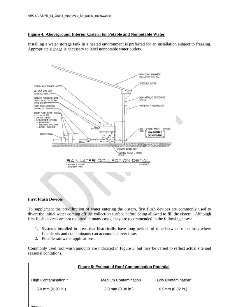
Figure 4: Aboveground Interior Cistern for Potable and Nonpotable Water Installing a water storage tank in a heated environment is preferred for an installation subject to freezing. Appropriate signage is necessary to label nonpotable water outlets.
First Flush Devices To supplement the pre-filtration of water entering the cistern, first flush devices are commonly used to divert the initial water coming off the collection surface before being allowed to fill the cistern. Although first flush devices are not required in many cases, they are recommended in the following cases:
1. Systems installed in areas that historically have long periods of time between rainstorms where fine debris and contaminants can accumulate over time.
2. Potable rainwater applications. Commonly used roof wash amounts are indicated in Figure 5, but may be varied to reflect actual site and seasonal conditions.
Figure 5: Estimated Roof Contamination Potential
High Contamination 1 Medium Contamination Low Contamination2
5.0 mm (0.20 in.) 2.0 mm (0.08 in.) 0.5mm (0.02 in.) Notes:

ARCSA-ASPE_63_Draft3_Approved_for_public_review.docx
23
There are many different styles of roof wash devices. The simplest versions involve filling a standpipe section of piping that contains adequate volume, that once full, then overflows into the cistern. (See Figure 6.)

ARCSA-ASPE_63_Draft3_Approved_for_public_review.docx
24
The volume of pre-wash for a nominal 4 in. (4.046 in. actual) diameter PVC pipe can be determined as follows in Figure 7a.
The volume of pre-wash for a nominal 6 in. (6.065 in. actual) diameter PVC pipe can be seen in Figure 7b.
End of Annex B
Figure 7a. 4 in. PVC Pipe Storage Volume
Length : feet (meters) Volume: liters (gallons)
1 (0.3) 2.6 (0.7)
3 (0.9) 7.6 (2.0)
5 (4.6) 12.5 (3.3)
10 (3.0) 25.4 (6.7)
15 (4.6) 38.1 (10.5)
Figure 7.b 6" PVC Pipe Storage Volume
Length : feet (meters) Volume: liters (gallons) 1 (.3) 5.7 (1.5)
3 (.9) 17.0 (4.5)
5 (4.6) 28.4 (7.5)
10 (3.0) 56.8 (15.0)
15 (4.6) 85.2 (22.5)
ARCSA-ASPE_63_Draft3_Approved_for_public_review.docx
25
Annex C Reference Definitions
(Informative) The following terms are commonly used in the rainwater catchment system industry, and the definitions are provided for informational purposes. AUXILIARY SUPPLY: A water supply arranged and protected from contamination that is available to provide an alternate means of filling a cistern. CALMING INLET: A device that permits water to enter a storage tank with minimal disturbance to particles that may have settled to the bottom of the tank. See Quiescent Flow. COLLECTION AREA: Area from which rainwater is collected for use in a rainwater harvesting system (e.g. roof area). DRY RUN PROTECTION: System for protecting the water pump against running dry. EVAPORATION FIELD: Element in the ground that is filled with gravel, ballast, or special non-permeable plastic elements and that stores rainwater that is fed into it on an intermediate basis before the water evaporates into the atmosphere or seeps into the surrounding soil. FIRE SPRINKLER RESERVE: Volume of water needed for fire protection that is not available for any other use and accessible only by the fire pump. HARVESTED WATER: Water gathered for the purpose of using for potable, nonpotable, or industrial applications. LEACH FIELD, EVAPORATION/TRANSPIRATION FIELD: Element in the ground that is filled with gravel, ballast, or special permeable plastic elements and that stores rainwater that is fed into it on an intermediate basis before the water seeps into the surrounding soil. MINIMUM WATER VOLUME: Recoverable water volume that is constrained by the process such that neither sediment nor scum can be sucked into the deliverable water. OVERFLOW LEVEL: The highest level that water from a drainage system can rise. OVERFLOW LINE: Line for leading away rainwater when the rainwater reservoir is full (e.g., into the storm drain system or seepage system). PRECIPITATION CHARACTERISTICS: Characteristics of a precipitation event (e.g., intensity, duration). PROCESS WATER LINE: System of lines from the process water pump to the individual points at which water is drawn. PROCESS WATER PUMP: Pumps process water from the rainwater reservoir to the points at which it is drawn.

ARCSA-ASPE_63_Draft3_Approved_for_public_review.docx
26
PROCESS WATER REQUIREMENTS: Planning value for the process water amount that is expected to be required in a specified period of time. PUBLIC WATER SYSTEM: System that is used by 25 or more different persons over a 60-day period. QUANTITY OF PRECIPITATION: Precipitation at a certain place, expressed as the water height over a horizontal area for a span of time under consideration. RAINWATER LINE: Supply, drainage, overflow, and emptying lines of a rainwater harvesting system. RAINWATER YIELD: Net water volume (water inflow), determined over a certain period of time, available for use as process water. Typically this is approximately 80% of theoretical collectable rainwater. SUBSURFACE IRRIGATION: Water that is applied below ground level, and is not directly exposed to the aboveground surface and/or surrounding air. SUPPLEMENTAL SUPPLY: Equipment for providing a supplemental supply of drinking water or non-drinking water into process water systems. SYSTEM CONTROL UNIT: Control unit for the automatic operation of the rainwater harvesting system. TRANSFER PUMP: A mechanical device to transfer collected water from downspouts to remote cisterns. USEFUL VOLUME: Volume that can be completely used during operation (Typically 80–90% of storage volume). YIELD COEFFICIENT: Ratio of the rainwater annually flowing into the rainwater harvesting system to the total amount of rainwater in the accompanying precipitation area , allowing for leakage, splashing, evaporation, etc. (typically 0.75–0.90).
End of Annex C
ARCSA-ASPE_63_Draft3_Approved_for_public_review.docx
27
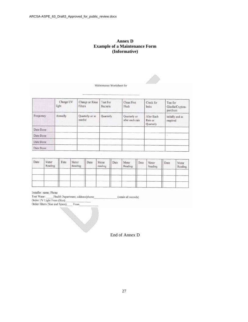
Annex D Example of a Maintenance Form
(Informative)
End of Annex D

ARCSA-ASPE_63_Draft3_Approved_for_public_review.docx
28
Annex E Calculation Procedure
(Informative) Step 1: Estimate demand Interior Water Requirement*: On average, a conserving American household uses 45.2 gallons per person/day to operate toilets, showers, clothes washers, sinks, and other water -using fixtures and appliances. Water demand can be minimized by using water efficient water fixtures. An example of how to estimate water demand is shown as follows:
Residential Indoor Water Use (Metric)
Fixture
Flow Rate
(liters per
use or min) **
Average #
uses/day or
min/day per
person
Daily Demand/ person
( L)
Number of people in household
Household Total Daily
Demand/ ( L)
Household Total
Monthly demand
( L)
Household Total
Yearly demand
( L)
Toilets 6.0 5.1 30.89 3 92.67 2,809 33,823 Shower (liters / minute) 6.3 5.3 33.31 3 99.90 3,028 36,469 Faucets (liters / minute) 6.3 8.1 50.91 3 152.70 4,626 55,733 Dishwasher (1997- 2001) (liters/use) 17.0 0.1 1.70 3 5.11 155 1,866 Clothes washer (1998 - 2001) (liters/use) 102.2 0.37 37.82 3 113.45 3,437 41,409 Total Demand 463.83 14,055 169,300 *Source: "Handbook of Water Use and Conservation" Amy Vickers, 2001, Waterplow Press, Amherst, MA, ISBN I-931579-07-5 ** Actual Flow (MFR)
ARCSA-ASPE_63_Draft3_Approved_for_public_review.docx
29
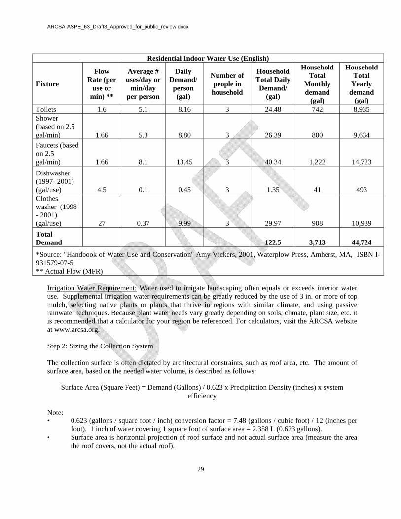
Residential Indoor Water Use (English)
Fixture
Flow Rate (per
use or min) **
Average # uses/day or
min/day per person
Daily Demand/
person (gal)
Number of people in household
Household Total Daily Demand/
(gal)
Household Total
Monthly demand
(gal)
Household Total
Yearly demand
(gal) Toilets 1.6 5.1 8.16 3 24.48 742 8,935 Shower (based on 2.5 gal/min) 1.66 5.3 8.80 3 26.39 800 9,634 Faucets (based on 2.5 gal/min) 1.66 8.1 13.45 3 40.34 1,222 14,723 Dishwasher (1997- 2001) (gal/use) 4.5 0.1 0.45 3 1.35 41 493 Clothes washer (1998 - 2001) (gal/use) 27 0.37 9.99 3 29.97 908 10,939 Total Demand 122.5 3,713 44,724
*Source: "Handbook of Water Use and Conservation" Amy Vickers, 2001, Waterplow Press, Amherst, MA, ISBN I-931579-07-5 ** Actual Flow (MFR)
Irrigation Water Requirement: Water used to irrigate landscaping often equals or exceeds interior water use. Supplemental irrigation water requirements can be greatly reduced by the use of 3 in. or more of top mulch, selecting native plants or plants that thrive in regions with similar climate, and using passive rainwater techniques. Because plant water needs vary greatly depending on soils, climate, plant size, etc. it is recommended that a calculator for your region be referenced. For calculators, visit the ARCSA website at www.arcsa.org. Step 2: Sizing the Collection System The collection surface is often dictated by architectural constraints, such as roof area, etc. The amount of surface area, based on the needed water volume, is described as follows:
Surface Area (Square Feet) = Demand (Gallons) / 0.623 x Precipitation Density (inches) x system efficiency
Note: • 0.623 (gallons / square foot / inch) conversion factor = 7.48 (gallons / cubic foot) / 12 (inches per
foot). 1 inch of water covering 1 square foot of surface area = 2.358 L (0.623 gallons). • Surface area is horizontal projection of roof surface and not actual surface area (measure the area
the roof covers, not the actual roof).

ARCSA-ASPE_63_Draft3_Approved_for_public_review.docx
30
• Precipitation density period is consistent with time period being considered (monthly, yearly, etc.). • This coefficient accounts for collection system loss from leakage, evaporation, roof composition,
etc. Roof coefficients are approximately 0.80–0.85. Step 3: Sizing the Storage (Adapted from Martin, T.J. (1980). Supply aspects of domestic rainwater tanks. South Australian Department of Environment, Adelaide.) Once the area of roof catchment has been determined and the average rainfall has been established, the maximum amount of rain that can be collected can be calculated using the formula: Runoff (Gallons) = A x (Rainfall – B) x Roof Area Where: A is the efficiency of collection, and values of 0.80–0.85 (i.e., 80–85% efficiency) have been used. B is the loss associated with adsorption and wetting of surfaces, and a value of 0.08 in. per month (2.0 in. per year) has been used (e.g. Martin, 1980). Rainfall should be expressed in inches and roof area in square feet. The maximum volumes of rainwater that can be collected from various areas of roof and at a range of average annual rainfalls are shown in Annex F. This information should only be used as an initial guide. If the maximum volumes are less than the annual water demand then either the catchment area will need to be increased or water demand will need to be reduced. The next step is to calculate the size of the tank. The tank needs to be large enough to ensure that: 1. The required volume of water can be collected and stored in the tank. 2. The volume of water in the tank will be sufficient to meet demand during the drier months or through periods of low or no rainfall. The simplest way of checking a tank size estimated to provide water throughout an average year is to use monthly rainfall data and to assume that at the start of the wetter months the tank is empty. The following formula should then be used for each month: Vt = Vt–1 + (Runoff – Demand) Where: Vt is the theoretical volume of water remaining in the tank at the end of the month. Vt–1 is the volume of water left in the tank from the previous month. Runoff should be calculated as discussed above (A = 0.80, B = 0.08 in.). Starting with the tank empty then Vt–1 = 0. If after any month Vt exceeds the volume of the tank, then water will be lost to overflow. If Vt is ever a negative figure, then demand exceeds the available water. Providing the calculated annual runoff exceeds the annual water demand, Vt will only be negative if periodical overflows reduce the amount of water collected so that it is less than the demand.

ARCSA-ASPE_63_Draft3_Approved_for_public_review.docx
31
Tank size is not necessarily based on collecting total roof runoff. For example, the maximum water that can be collected from a roof area of 20 square feet with a monthly rainfall of 4 in. will be about 40 gallons. If the water demand is less than this, some overflow may occur while demand is still met. If water demand is to be met throughout the month, the tank should be large enough so that Vt is never negative. Calculations should be repeated using various tank sizes until Vt is 0 at the end of every month. The greater the values of Vt over the whole year, the greater the security of meeting water demand when rainfalls are below average or when dry periods are longer than normal. The greater the security, the higher the cost of the tank. Step 4: System Adjustment To optimize performance and cost, going back through the calculation and modifying surface area and the cistern storage capacity is recommended.
End of Annex E

ARCSA-ASPE_63_Draft3_Approved_for_public_review.docx
32
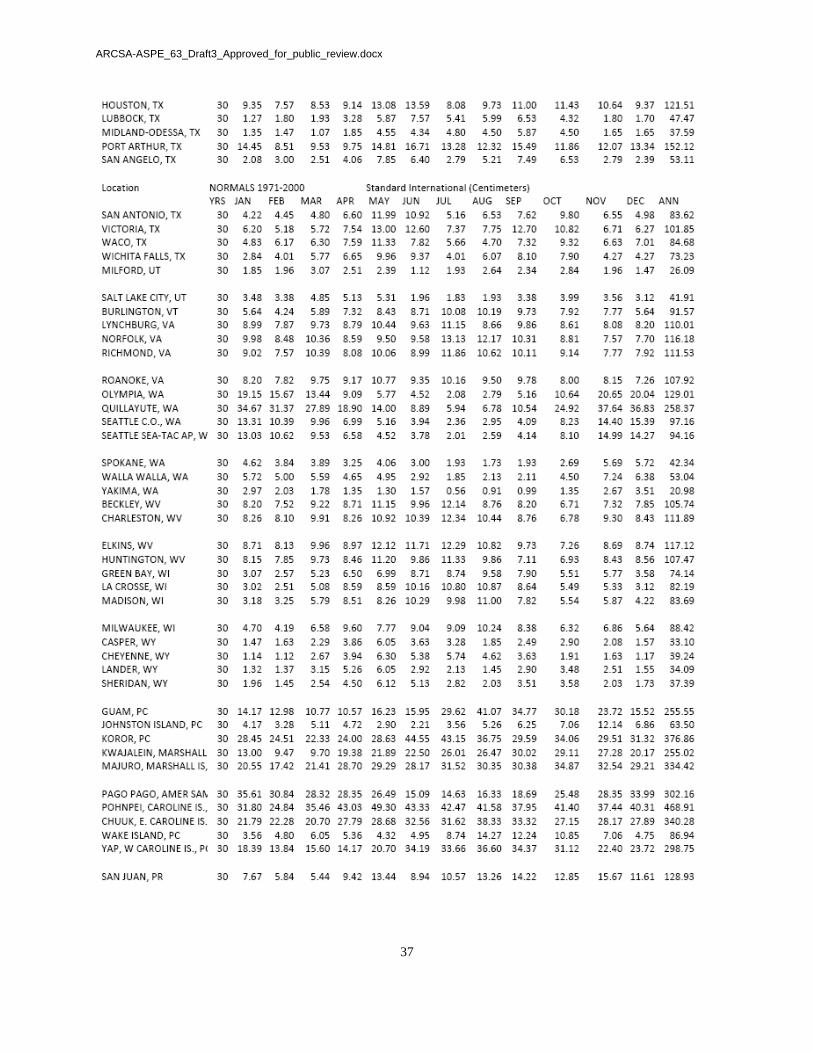
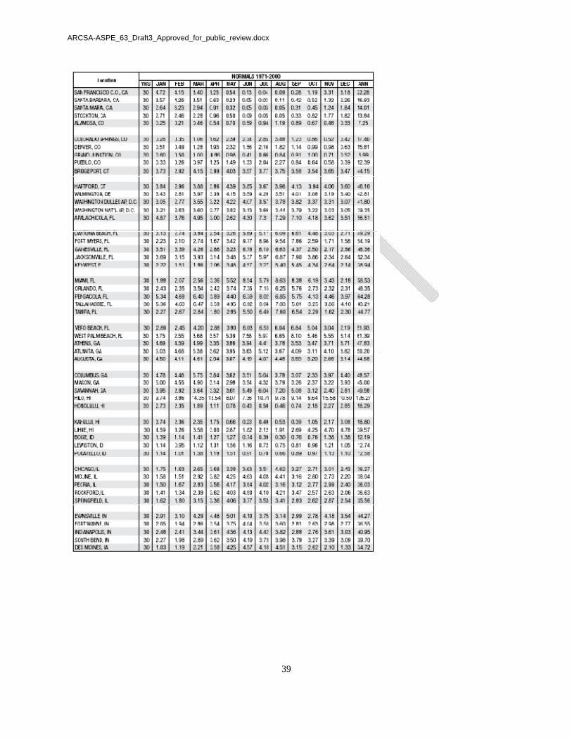
Annex F Average Rainfall Data (Informational)

ARCSA-ASPE_63_Draft3_Approved_for_public_review.docx
33

ARCSA-ASPE_63_Draft3_Approved_for_public_review.docx
34

ARCSA-ASPE_63_Draft3_Approved_for_public_review.docx
35

ARCSA-ASPE_63_Draft3_Approved_for_public_review.docx
36
ARCSA-ASPE_63_Draft3_Approved_for_public_review.docx
37

ARCSA-ASPE_63_Draft3_Approved_for_public_review.docx
38
ARCSA-ASPE_63_Draft3_Approved_for_public_review.docx
39

ARCSA-ASPE_63_Draft3_Approved_for_public_review.docx
40

ARCSA-ASPE_63_Draft3_Approved_for_public_review.docx
41

ARCSA-ASPE_63_Draft3_Approved_for_public_review.docx
42

ARCSA-ASPE_63_Draft3_Approved_for_public_review.docx
43