archline.xp 2009 new features
DESCRIPTION
ARCHLine.XP 2009 New FeaturesTRANSCRIPT

ARCHLine.XP® 2009 News
ARCHLine.XP® 2009
Windows
News
User's manual
CadLine
Information in this document is subject to change without notice and does not represent a commitment on the part of CadLine. The software, which includes the information contained in any databases, described in this document is furnished under a license agreement or nondisclosure agreement. The software may be used or copied only in accordance with the terms of the agreement. It is against the law to copy the software on any medium except as specifically allowed in the license or nondisclosure agreement. The licensee (purchaser) may make one copy of the software for the purpose of creating a -backup copy. No part of this manual may be reproduced, transmitted, transcribed, or translated into any language in any form or by any means, without the express written permission of CadLine. 2009. CadLine. All rights reserved. In no event shall CadLine be liable for special, indirect or consequential damages in connection with or arising from the use of this document or any programs contained herein. Microsoft, MS, and MS-DOS are registered trademarks and Windows is a trademark of Microsoft Corporation. ARCHLine.XP® is a trademark of CadLine. This manual was produced using Microsoft Word and ARCHLine.XP®.

3
ARCHLine.XP® 2009 News
Contents 1. DirectX ......................................................................................................... 5
1.1. Use DirectX......................................................................................... 6 1.2. Walk and Fly ..................................................................................... 17
2. Markers ...................................................................................................... 21 2.1. Markers’ operation ............................................................................ 21 2.2. Markers’ behaviors in different views ................................................ 23 2.3. Types of markers and accessible commands ................................... 24 2.4. Design layered walls and slabs......................................................... 26 2.5. Marker settings ................................................................................. 27
3. 3D Warehouse ........................................................................................... 30 4. Layer groups ............................................................................................. 33 5. Truss .......................................................................................................... 36
5.1. Truss preferences ............................................................................. 36 5.2. Placing truss ..................................................................................... 40
6. Openings in the Curtain wall.................................................................... 41 7. 3D extension of line nature elements...................................................... 44
7.1. Function ............................................................................................ 44 7.2. Custom setup of the line nature elements......................................... 45 7.3. Example ............................................................................................ 46
8. Extension of DWG import......................................................................... 48 9. Design Center............................................................................................ 49 10. Drawing recovery manager ...................................................................... 52 11. Quick View Toolbar................................................................................... 55 12. Building volume control ........................................................................... 58
12.1. How to use ........................................................................................ 58 12.2. Editing volume model........................................................................ 62
13. Solar access protection............................................................................ 64 13.1. Information ........................................................................................ 64 13.2. How to use ........................................................................................ 65
14. Symbol at line end points......................................................................... 70 14.1. Settings of line endings..................................................................... 70 14.2. Customized arrowhead symbols ....................................................... 72

4
CadLine
15. Replacing of groups or object ................................................................. 73 15.1. How to use ........................................................................................ 73
16. Plot layout developments......................................................................... 77 17. Picture on wall........................................................................................... 80
17.1. Properties.......................................................................................... 80 17.2. Placing Picture on wall ...................................................................... 83
18. Elevation shadow...................................................................................... 84 18.1. Vectorial elevation shadow ............................................................... 84 18.2. Image elevation shadow ................................................................... 85
19. Others ........................................................................................................ 90 19.1. Window selection tabs ...................................................................... 90 19.2. Switching the reference line of walls ................................................. 92 19.3. Object selection ................................................................................ 95 19.4. Status bar.......................................................................................... 95 19.5. Bending wall layers in case of reveal ................................................ 95 19.6. Wall - Place Frontal View.................................................................. 97 19.7. Backup save ................................................................................... 100

5
ARCHLine.XP® 2009 News
1. DirectX
Introduction The ARCHLine.XP® 2009 put the appearance of drawing and 3D contents on different technological bases. This new technology is the Microsoft DirectX. The DirectX is such a driver for computers running Microsoft Windows operating systems, that you can also use for the accelerating methods offered by the hardware. With help of DirectX the ARCHLine.XP® can use efficiently the ability of the video card, which is the most important device in the appearance.
More about DirectX Briefly about the DirectX technologies without completeness. The DirectX is a package of Microsoft for Windows operation system. From the Windows 95 the DirectX is the organic part of Windows. It is also applied in such software, where the fast and true-life appearance is important. It is important, that the DirectX gives a possibility to represent 3D and 2D contents faster and in higher quality.

6
Due to this you have a chance to handle larger and more complicated plans and other drawings or models, in such way, that the processor responsible for general calculations gets a little or not at all gets load. It is very useful because the work will be easier as the video card makes the representation, which is very hard work in many cases.
1.1. Use DirectX When you start ARCHLine.XP® 2009, it recognizes automatically the ability of the graphic card and arranges the work for it. If the video card can do it, the hardware-accelerated appearance will be default automatically with the help of DirectX technology. On older computers the program changes to a slower hardware not accelerated display method.
So you don’t have to switch on/off the DirectX representation, it’s automatic. You can get information from the representation method by controlling the icon on the left side of the header in the active window. If you see the icon, it means, that the content of the window appears faster. If you see the icon, the content of the window appears with a slower and processor load method.
1.1.1. DirectX settings You have new settings and fine-tuning possibilities with introducing DirectX. It has to be emphasized that if the quality of the represented 2D and 3D content is required, you don’t need the following mentioned settings modifications or fine tunes.
When the ARCHLine.XP® runs on such computer, that supports the DirectX technology, there is a possibility to fine-tune the quality of the displayed content. Fundamentally we can mention two types of settings area in this respect: the representation settings of 2D windows and the 3D windows. The modification of settings depends on, that which window is active. For example if a 2D (floor plan) window is active, then you can modify that settings belonging to it with opening Property. For this click on Property on the bottom of Toolbox:
It is important not to select any drawing elements in the active window, because in this case the Property represents the preferences of the selected element.
CadLine
7
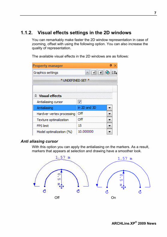
1.1.2. Visual effects settings in the 2D windows You can remarkably make faster the 2D window representation in case of zooming, offset with using the following option. You can also increase the quality of representation. The available visual effects in the 2D windows are as follows:
Anti aliasing cursor With this option you can apply the antialiasing on the markers. As a result, markers that appears at selection and drawing have a smoother look.
Off On
ARCHLine.XP® 2009 News

8
Antialiasing The antialiasing can be applied to the representation of the content in the selected window types. There are four options:
Off The Off setting means that there is no antialiasing. In that case the contents of the 2D and 3D windows look coarser.
Only in 2D The Only in 2D setting means that antialiasing is applied only to the content of the 2D (floor-plan) windows.
Off On
Only in 3D The Only in 3D setting means that antialiasing is applied only to the content of the 3D windows.
In 2D and 3D The In 2D and 3D setting means that antialiasing is applied to the content of all windows in the project.
Off On
CadLine

9
ARCHLine.XP® 2009 News
Hardware vertex processing With hardware vertex processing the video card stores and processes the data of vertices found on the drawings. Since two vertices belong to each line, it is easy to imagine the amount of vertices on a drawing. Hardware vertex processing can speed up your work if you have a fast video card.
Texture optimization Texture optimization is a useful setting if you have large drawings. Using this setting, the program antialises only the visible content of a window, while the appearance of the content outside the window (which is not visible) is simplified substantially. This simplification is visible at pan. However, the visible content is refreshed as soon as the pan is finished, and then it looks smooth again. By enabling the texture optimization it is possible to use the FPS limit and Model optimization (%) options too.
FPS limit FPS stands for frames per second or we can say images/second. The program tries to represent the content of any windows with the highest speed that it is possible. This speed is expressed in frames per second, which means the number of frames represented consecutively in one second. (When representing a moving model or a video, at least 24 frames/second are needed to make full motion for a human eye.) When the program detects that it is not possible to keep the limit value, it starts to simplify the representation of the content by texture optimization.
Model optimization (%) Model optimization (%) is an adjustable checking function. Setting 10% here, for example, means that the program checks whether the specified FPS limit can be kept or not only at that time when 10% change has been made in the project compared to the previous checking. If yes, then it switches off the texture optimization automatically because there is no need of it for increasing the speed. If it finds that the specified FPS limit cannot be kept, then it leaves the texture optimization switched on to increase the speed.
1.1.3. 3D window graphics settings 3D window graphic settings are the following: Render settings Shadow Sunlight

10
CadLine
Camera Visual effects

11
ARCHLine.XP® 2009 News

12
1.1.3.1. Render settings
Render type With the options found here you can set the rendering type used for the representation of the model.
Wireframe In wireframe representation each edge of the model is visible.
Hidden line In hidden line representation the program displays only the edges of the model that can be seen from the current view. The program doesn’t display the hidden lines in the background.
Shaded
Shaded means that the surfaces of the model are represented with the color properties specified for the used materials. Only the surfaces that can be seen from the specific view are displayed.
Material color (With wireframe) This representation is the combination of Shaded and Hidden line rendering types.
CadLine

13
Textured Textured representation means that the surfaces of the model are displayed with the texture properties specified for the used materials (if the texture property is not specified for a material then the material color is used instead). Only the surfaces that can be seen from the specific view are displayed.
Textured (With wireframe) This representation is the combination of Textured and Hidden lines rendering types.
X-ray The X-ray rendering type is similar to the Textured (with wireframe). The difference is that non-transparent surfaces become transparent and therefore the structure of the model can be overviewed in unique and spectacularly way, similarly to an X-ray photo.
ARCHLine.XP® 2009 News

14
X-ray transparency (%) When X-ray is selected from the Render type options, you can specify the amount of transparency. You can specify a value between 0% and 100%.
Texture mixed with material color There is a possibility to mix the textured representation with the material color. So you can reach an effect as you repaint the texture. We offer to switch on the option by Textured render setting. In the next example you can see the cover of the terrace with textured representation:
Off
Try the option with changing the color assigned to the material to green or yellow.
CadLine

15
On with green color On with yellow color
Approximation lines For the representation of arc surfaces you can switch on the displaying of approximation lines.
Transparency Using this option you can make the edges behind surfaces with transparent materials visible.
1.1.3.2. Shadow
Show shadows With this option it is possible to represent shadows in the model.
1.1.3.3. Sunlight
Enable sunlight Enable the sunlight with the option.
ARCHLine.XP® 2009 News

16
CadLine
Ambient factor It shows how the materials react to ambient light depending on the sunlight.
Diffuse factor It shows how the materials react to diffuse light depending on the sunlight.
Specular factor The intensity of shine is important primarily in case of arc surfaces, depending on the sunlight. The color of shining of the material with specular factor property can be specified here.
1.1.3.4. Camera
Walk speed It is called walking when we move in the model with the move keys. The speed of walking can be specified here. The measure of this is meter/second.
Run speed It is running when we move in the model with the move keys, while the ’run’ key is pressed and hold. The speed of running can be specified here. The measure of this is meter/second.
Enable camera light With this option the camera light can be switched off and on. It is recommended to use this option switched on.
Ambient factor It shows how the materials react to ambient light depending on the camera light.
Diffuse factor It shows how the materials react to diffuse light depending on the camera light.
Specular factor The intensity of shine, depending on the camera light is important primarily in case of arc surfaces. The color of shining of the material with specular factor property can be specified here.

17
1.1.3.5. Visual effects Properties that can be set in the Visual effects group are equal with the ones we have already mentioned in chapter Visual effects settings in the 2D window, completed with Hardware mesh handling and Texture quality.
Hardware mesh handling Hardware mesh handling can be used with video cards with large memory size. In case of hardware mesh handling the whole model is stored on the memory of the video card and therefore the result of this is much faster work.
Texture quality Here you can specify the representation quality of the materials used by the model in DirectX 3D windows. Depending on the selected option the program may override the original texture resolution and represents the materials of the model with poorer quality than the original. The following options are available: Low Medium High Maximum
Example
Low Medium
High Maximum
1.2. Walk and Fly
ARCHLine.XP® 2009 News

18
You can represent in higher quality the 3D content of your projects with the
help of the View - Walk and Fly commands. This new function will help you, when you would like to show in real the different details of the model. You can do it in that way, as you walk in the building in the reality. You can apply the commands excellently in course of work, because the different settings of perspective views and design are become simple. You can edit the different open space border elements, as if you stand in the model and work on a virtual space.
You can start the Walk and Fly commands with clicking on the View - Walk and Fly icon. It works only in that case if you activate the 3D DirectX window.
1.2.1. Terminology The difference between the Walk and Fly is the moving method in the virtual model.
Walk In course of walk – like in the reality – the viewpoint height of the spectator doesn’t change. When you move in the model with the help of walk, then it moves the viewpoint (the camera) on a fixed horizontal plane.
Fly In course of fly the viewpoint height of the spectator can change as if it flies the model. This function can be important, when you need higher freedom of movement from Walk. You can reach down and up different levels (for example movement on the step) owing to the freedom open space coordination independently from the size of the model. Because of the just mentioned things we have to explain about the camera. The camera is that point in the open space, from where we look at the part of the model. The target point and the camera determine together that direction in which the spectator looks. The visual angle is important, because maybe you need wider visual angle in viewing narrow spaces to see the proper part of the model.
CadLine

19
1.2.2. Treatment
You can start the Walk and Fly commands to click on the View - Walk and Fly icon. When you use the Walk or Fly commands, the mouse cursor is disappeared and you can move in the space by the help of mouse and the keyboard. You can change the direction of view with the mouse, while you can move in the space with the proper button of keyboard. It is really similar to the movement in the reality, because we can move and look around at the same time. It is easier to understand if you imagine the mouse as the head of the spectator, and the keyboard as the body of the spectator. You can interrupt the Walk or Fly command with: Press down ESC Left click Right click
1.2.2.1. The usage of the mouse In course of using Walk and Fly functions the mouse determines the view and walk direction. You just have to move the mouse there is no effect of the click. When you draw the mouse to yourself, then the spectator will look down otherwise upward. The moving of mouse controls the dimension of this. If you would like to look right or left, move your mouse to the right or left. Start a command, move your mouse and study the effect.
1.2.2.2. The usage of keyboard You can use two sorts of keyboard layout to the keyboard movement. For this you need the following table. 1. layout 2. layout Effect Cursor up W Move forward Cursor down S Move backward Cursor left A Move left Cursor right D Move right Space Space Viewpoint lifting C C Viewpoint sinking Shift Shift Run
ARCHLine.XP® 2009 News

20
You can interrupt the Walk or Fly command with: Press down ESC Left click Right click
1.2.2.3. Move in open space It is practical to learn the movement in open space to move efficiently in it. For this you need the mouse and the keyboard at the same time.
• Put one of your hands on directions button of the keyboard, and the other one on the mouse.
• Start the Walk and Fly command. • After this press down the Move forward button, and move the mouse at once.
You can note that it will move to the direction you are looking at. You can combine the movement method as you wish according to the simple example mentioned previously, so you have a possibility to complex move in the open space.
CadLine

21
ARCHLine.XP® 2009 News
2. Markers
ARCHLine.XP® markers are such interactive interface tools that help with modifying elements after their selection without using menus.
Introduction The main point of using ARCHLine.XP® markers is that it is very easy to handle them. Appearance of markers can be various depending on their aim. After indicating every drawing element special markers belonging to that element appear and with help of special markers frequent modifications can be completed quickly. Using markers, reduces time, increases design speed and can be learned easily.
2.1. Markers’ operation Markers appear when you select one or more elements. Markers can be used by left mouse button. There are different types of markers: Endpoint, edge marker, rotate, move and dimension marker.
Rotate marker
Endpoint
Move marker
Dimension marker
Edge marker

22
Clicking on a marker with left mouse button a menu appears where you can choose from possible commands:
Example for endpoint:
Example for edge marker: It appears with clicking on the edge of the element:
Learning mode At first start of the program Learning mode is not switched on, markers have to be used as written above. Using Learning mode work can be quickened in this case markers remember the last command. Learning mode can be switched on with settings of dialog window Markers, which can be found in menu point File menu – Preferences – General, see chapter Markers’ settings. After switching on learning mode markers react on short and long clicks in a different way.
CadLine

23
ARCHLine.XP® 2009 News
Learning mode Effect
Short click The last command is executed. Long click The menu appears.
Moving the cursor above a marker its shape changes and the marker takes the shape of the last command icon used there: with a short click this command is executed.
! Using Learning mode is offered only for experienced users!
2.2. Markers’ behaviors in different views Ground plan window
After selecting an element endpoints and edge markers always appear in Ground plan window. If the selected element is seen on the screen in too small size, move, rotate and dimension markers don’t appear. In this case if you want to use these markers, enlarge the element with help of mouse runner until the markers appear.
General 3D window Move, rotate and dimension markers appear in General 3D window if the selected elment is seen on the screen in quite a big size similarly to Ground plan window. Rotate and dimension markers are not seen in certain views, in this case if you want to use these markers rotate the model with help of arrow keys until the markers appear.
Section window In Section windows and in General 3D windows representing profile a limited set of markers can be accessed.The commands here work on the level parallel to window level and not to model XY level.

24
2.3. Types of markers and accessible commands
Rotate marker
Endpoint
Move marker
Dimension marker
Edge marker
Move markers
Move markers take place in the centre of elements and they make their moving and lifting possible. In 3D window elements can be moved in parallel with ground plan’s level and they can be lifted at right angles to ground plan’s level. However in case of objects fitted to vertical or inclined level there is a possibility of moving them on fitting level as well. Menu belonging to move markers generally contain the following commands:
Move or Move a Copy From (starting point of moving is the centre of element)
Move From or Move a Copy From (starting point of moving has to be given as well)
In 3D window there are further commands:
Lift or Lift a Copy (starting point of lifting is the centre of element)
Lift From or Lift a Copy From (starting point of lifting has to be given)
CadLine

25
If you put an object into 3D window and during this process a certain level –which is different from horizontal – was given, in the 3D window instead of Lifting command the following commands can be found:
Move on its own level or Move a Copy on its own level (moving starting point is the centre of element)
Move From on its own level or Move a Copy From on its own level (moving starting point is has to be given)
Rotate markers
Rotate markers allow rotating and mirroring of elements. In 3D window Rotate markers allow to rotate and mirror elements. In 3D window elements can be rotate around an axis perpendicular to ground plan and they can be mirror to the plane perpendicular to ground plan. Menu belongings to move markers generally contain the following commands:
Rotate or Rotate a Copy (the center of rotating is the move marker and only the endpoint of rotating angle has to be given)
Rotate From or Rotate a Copy From (the centre of rotating and the starting- and endpoint of rotating angle have to be given)
Mirror or Mirror a Copy (two points of mirror axis or center of the mirroring have to be given)
Endpoints Endpoints indicate significant points of elements. A part of commands connected to them alter (change) the shapes of elements. For example an endpoint menu belonging to Hatch contour contains the following commands:
Move node
ARCHLine.XP® 2009 News

26
CadLine
Delete node
Fillet
In menus belonging to Endpoints generally commands for moving the whole element can be found as well:
Move or Move a Copy (moving starting point is the given endpoint)
Rotate or Rotate a Copy (rotating center is the given endpoint)
In 3D window further commands can be found:
Lift or Lift a Copy (lifting starting point here is the given endpoint)
Edge markers Edge markers allow modifying the edges of elements. For example the menu of an edge marker belonging to Hatch contour contains the following commands:
Offset
Offset all
Insert Node
Turn to Curved Edge
Dimension markers Dimension makers indicate the dimension of walls, openings and lines. A certain dimension can be changed with a click on the dimension value. In case of modifying the length an arrow can be found at the end of dimension line and it shows that end of element, which moves in modifying. Clicking on this arrow its direction can be reversed.
Mirror marker In case of openings another mirror marker helps with transforming doors’ and windows’ position.
2.4. Design layered walls and slabs Each layer of layered walls and roofs can be designed with help of markers. For designing a layer you have to select an element with clicking left mouse button and at the same time you keep ALT key pressed down. Then edge

27
markers appear on the element with dotted line, indicating that the given layer can be designed.
If you select the element as written above, menus of holding points and edge markers contain such commands that help to design contour of the selected layer.
Layer changing markers Layer changing markers help to change layers of layered walls and roofs. Menu of these markers contains the following commands:
2.5. Marker settings You can get marker settings in a dialog window Marker settings, which can be found in the program in menu point File menu – Preferences – General.
ARCHLine.XP® 2009 News

28
Enable marker Markers can be switched on and off in the program with this switch. After installing the program the option is in switched on mode.
Marker color 2D You can set in the colors of markers that appear in the ground plan’s windows of the program. Click on the color area on the right to modify (change) value then choose a color from the color charts and press down the key OK at last.
Marker color 3D You can set in the colors of markers that appear in 3D windows. To change value click on the color are on the right then choose a color from the color charts and press down the key OK at last.
Marker scale You can increase dimension of markers because of screen resolution or other facts. To change value chooses one from the rolling list on the right.
Learning mode In this mode you can set in that shortcut menu of markers can remember or not the last commands. If you switch on the option, it allows remembering the last used operations for the program. Then the program indicates the actual default command in shortcut menu in bold type.
CadLine
29
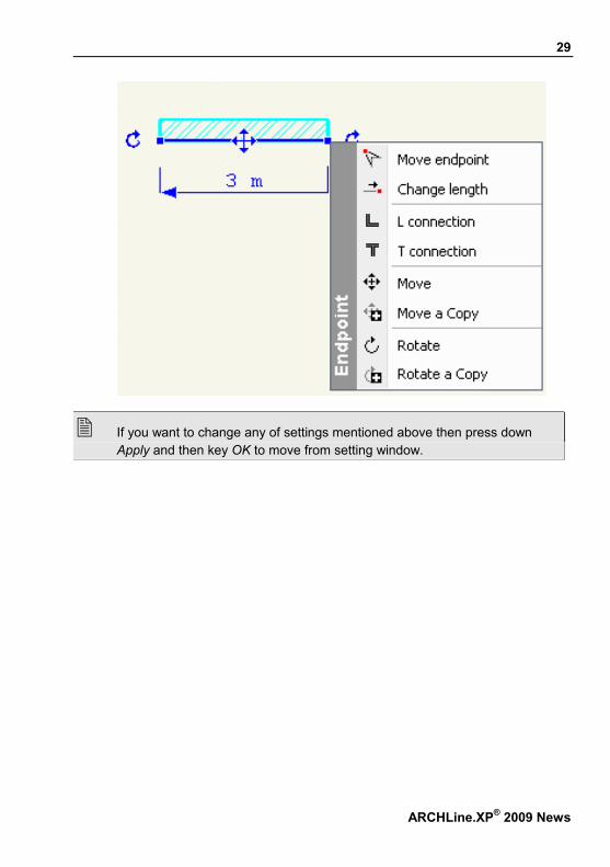
If you want to change any of settings mentioned above then press down Apply and then key OK to move from setting window.
ARCHLine.XP® 2009 News

30
CadLine
3. 3D Warehouse
Google 3D Warehouse™ is a free Google service by which anyone can download and use web-published 3D models for free. 3D Warehouse™ is a continuously growing database of models which can be represented in the projects with different textures. There is a wide range of models, including buildings, furniture, cars, people and many other objects. With the help of 3D Warehouse™ models it is easy to furnish a flat in your design project because you can download a lot of furniture models and furnish a virtual flat spectacularly as soon as you finished with the designing of walls, slabs, doors and windows, stairs etc. ARCHLine.XP® is integrated with Google 3D Warehouse™ web portal. This integration means that the selected model can be inserted directly into an ARCHLine.XP® project and ARCHLine.XP® object library.
How to use The command, which can be used in a 2D and 3D window, too, is available in the File menu - Import submenu:
! Please note that you need a live internet connection to use this command!
The 3D Warehouse command pops up a browser window that is connected directly through the internet to the Google 3D Warehouse web portal.

31
On the web portal you can search for models or collections. Use English keywords like table, chair, bed, sofa, curtain, lamp etc., if you want to search for models. If you look for collections, use Ikea, SmartFurniture, Whirlpool etc. keywords. As soon as you found the requested item, click the Download Model button.
ARCHLine.XP® 2009 News
32
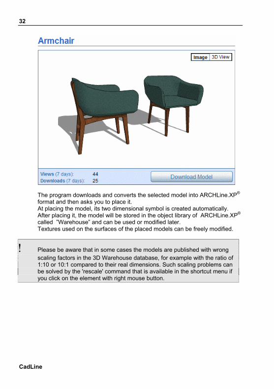
The program downloads and converts the selected model into ARCHLine.XP® format and then asks you to place it. At placing the model, its two dimensional symbol is created automatically. After placing it, the model will be stored in the object library of ARCHLine.XP® called ”Warehouse” and can be used or modified later. Textures used on the surfaces of the placed models can be freely modified.
! Please be aware that in some cases the models are published with wrong scaling factors in the 3D Warehouse database, for example with the ratio of 1:10 or 10:1 compared to their real dimensions. Such scaling problems can be solved by the 'rescale' command that is available in the shortcut menu if you click on the element with right mouse button.
CadLine
33
ARCHLine.XP® 2009 News
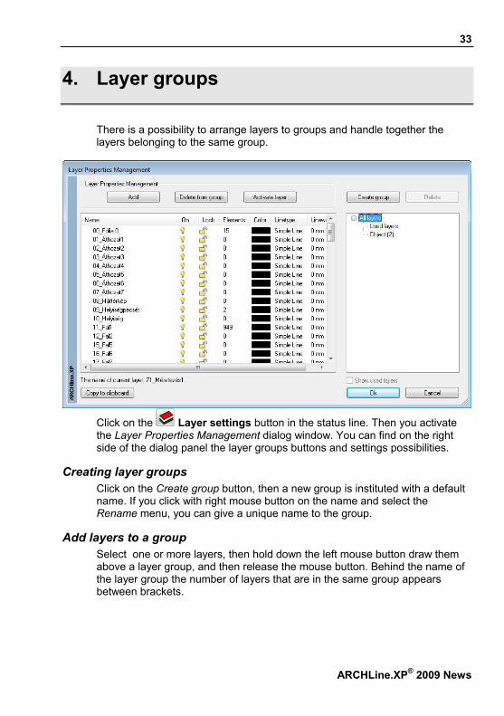
4. Layer groups
There is a possibility to arrange layers to groups and handle together the layers belonging to the same group.
Click on the Layer settings button in the status line. Then you activate the Layer Properties Management dialog window. You can find on the right side of the dialog panel the layer groups buttons and settings possibilities.
Creating layer groups Click on the Create group button, then a new group is instituted with a default name. If you click with right mouse button on the name and select the Rename menu, you can give a unique name to the group.
Add layers to a group Select one or more layers, then hold down the left mouse button draw them above a layer group, and then release the mouse button. Behind the name of the layer group the number of layers that are in the same group appears between brackets.

34
Display Layer groups Select a layer group from the list of All layers, then on the left side of the dialog window only the layers belonging to the selected group appear. You can qualify the appearing list if you switch on the Show used layers button. The list of layers group contains two built in layer groups: if you select the All layers group, all the layers of the given window appear, if you select the Used layers group then that layers will be visible from the all layers, which contain elements unrelated to the position of Show used layers button.
Transactions with Layer groups
If you click with right mouse button on the name of a layer group, with help of the appearing shortcut menu you can modify the preferences of all layers at once: you can represent (On), or hide (Off), lock or unlock all layers in the given group at once.
Delete from group Select a layer group from the list of Layer groups, then on the left side of the dialog window only the layers belonging to the same group appear. Select one or more layers then click on the Delete from group button. The given layers are deleted only from the layer group, and they are available if you select the All layers group. If you select layers from All layers and Used layers group, instead of Delete from group button you find the Delete button, which deletes the layers definitely.
Delete layers group Select a layer group then click on the Delete button on the upper right corner of the dialog window. Then only the layer group will be deleted, the layers in it are available further if you select the All layers group.
CadLine

35
ARCHLine.XP® 2009 News
The layers groups have to be determined according to windows similarly to the layers.
Example: In the following example it is a really great help using the layers group:
• Start a new project. • Load in a DWG file, which contains more than 30 layers. • Create a new layer group: DWG layers. • Click on the right side on the Used layers group. Then on the left side only the
layers imported from dwg drawing and the used layers can be found. • Move all layers from here to the DWG layers group. • Start design. • If the imported elements from dwg drawing are not needed, you can switch off
or lock them in one step.

36
CadLine
5. Truss
In the Toolbox Modeling - - Beam folder there is a new element, the Truss.
In architecture and structural engineering, a truss is a structure comprising one or more triangular units constructed with straight slender members whose ends are connected at joints referred to as nodes. ARCHLine.XP® manages planar truss where all the members and nodes lie within a two dimensional plane. For more details about truss see http://en.wikipedia.org/wiki/Truss. ARCHLine.XP® enables you to place truss on the current layer.
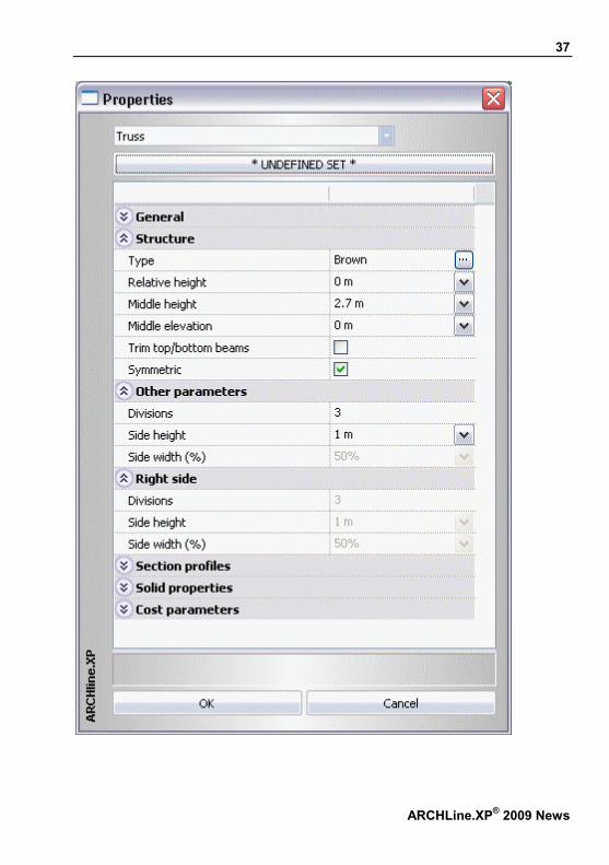
5.1. Truss preferences Before you place a truss, you have to determine its properties. The truss properties can be set in the Modeling toolbox - Properties - Truss dialog. After the selection of command a dialog window appears with properties of Truss.
General properties First there are the general properties of the truss: layer, color, line type, line width, priority.
Sets You can save the set truss properties to set, and the set can be stored in environment. Then you can use the beam structure in any of your plan. Clicking on the button the earlier defined truss sets appear on the right side of the dialog window.
37
ARCHLine.XP® 2009 News

38
Structure Type You can select the following types: Vierendeel, Brown, Howe, Pratt, Warren 1, Warren 2.
Relative height The height of the actual floor compare to its 0 level.
Middle height It means the distance between the under and upper belt in the middle of the truss.
Middle elevation The height of the middle point of under belt compare to the height of the side points.
Trim top/bottom beams If You switch on the option, the program trim the top and bottom beam at the connection of perpendicular beams.
Symmetric In switched on status the length of the truss right and left side, the height of the truss on the two outside points, and the number of right-and left side divisions are the same. You can define these parameters separately in switched off status.
CadLine

39
Other parameters
Divisions The number of perpendicular beams, that connect the under and upper belt on the right or left side. You can set the height of the right side only in that case if the Symmetric button is switched off.
Side height The distance between the under and upper belt on the right or left side of the truss: You can set the height of the right side, if the Symmetric button is switched off.
Side width (%) The length of the right or left side compare to the length of the truss, expressed in %: You can set the height of the right side, if the Symmetric button is switched off.
Section profiles Trusses are characterized by their cross-sectional profile. Therefore first select the cross section in the Select profile dialog box and specify the cross-sectional parameters of the column. You can assign profile for the following parts of the truss: Bottom, Top, Side, Vertical, Diagonal
Custom reference points If it is switched off all elements profile of the truss with its centre point fit to the geometrical centre point of the truss. If it is switched on the determined reference points of profiles by different groups define the position.
Solid properties You can set the solid and surface material of Truss. If you click twice on the material name from the Material dialog window you can select the proper material type.
ARCHLine.XP® 2009 News

40
Cost parameters You can assign cost parameters to the truss, as to any other elements.
5.2. Placing truss After setting the truss properties select the Truss from the Modeling toolbox – Beam folder. You can place truss in 2D drawing and 3D view as well. Specify the starting point then drag the cursor in the proper direction and define the endpoint of the truss. Beside the endpoint appears the profile of the truss, which signs the active reference point.
CadLine

41
ARCHLine.XP® 2009 News
6. Openings in the Curtain wall
You can easily prepare complex glazed structures, curtain walls. After preparing the main structure elements you can fit without restriction openings to the curtain wall fitting to the structure elements.
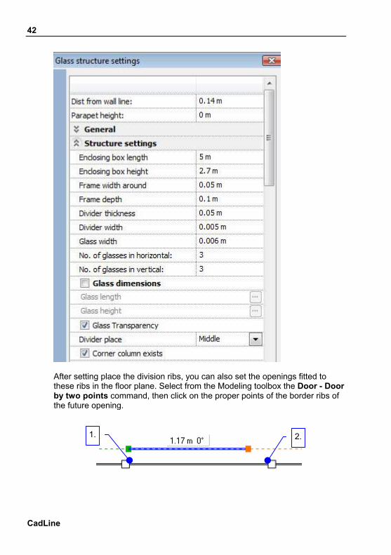
Use First prepare the curtain wall, and set the position of the main structure elements: set the properties of Number of glasses and Glass dimensions (After selecting the element these properties can be found in the Property manager under the Structure settings headword or they can be found in the shortcut menu under the Properties menu point after clicking on the element with right mouse button.
42
After setting place the division ribs, you can also set the openings fitted to these ribs in the floor plane. Select from the Modeling toolbox the Door - Door by two points command, then click on the proper points of the border ribs of the future opening.
2.1.
CadLine

43
If the external contour of the opening is modified as the result of fitting in the opening the reveal structure of the curtain wall follows these changes.
ARCHLine.XP® 2009 News

44
CadLine
7. 3D extension of line nature elements
There is a possibility to create line nature elements designed in the 3D window into 3D form. . You can create necessary simple models in the conception planning phase fast and easily, what’s more this method can be used well for creating surface nature elements necessary to the detailed spectacle plans.
7.1. Function You can create those line nature elements into 3D form that we placed in the 3d window with active global work plane. The 3D surface or body is created, that we draw out the line to the space perpendicularly to its own plane. You can form the following types of elements into 3D:
Line Polygon Circle Arc Ellipse Elliptic arc Spline

45
There is no own plans of straight lines, in this case the surface is created by drawing out the line parallel to the Z-axis.
The breaking of created arched surfaces is determined by that in the
moment of drawing out in the Build 3D model which resolution is set. If you change later the resolution by upgrading the 3D window this change has no effect on these elements.
7.2. Custom setup of the line nature elements In the 3D window you can reach the line transforming into 3D form by determine the following properties: (These properties can be found in the Property manager after selecting the element or they can be found in the shortcut menu under the Properties menu point after clicking with right mouse button on the element.)
Line width These values determine the height of the 3D solid (the line nature element perpendicular dimension to its own plane, the value of lifting). The value is 0 by default then the elements behave as simple lines.
Solid Closed formations (circle, ellipse, closed polygon) are formed in two ways to 3D solid: if the Solid button is switched off, the result will be a surface if it is switched on we create a solid 3D.
Solid material After creating the 3D solid, the Solid material appears in the dialog window when you want to modify another property.
ARCHLine.XP® 2009 News

46
7.3. Example Create a curtain in front of the window.
• Set the work plane to the upper plane of the window-niche in the 3D DirectX window (the direction is down)
• Draw a spline on the surface • Modify the properties of the spline: set the width, for example: 1,6 m (for the
selection of the spline it is recommended to use a wire frame view) • Modify again the properties: Select the Textile-dots material • It is recommended to save the ready 3D form to the object library.
CadLine

47
ARCHLine.XP® 2009 News

48
CadLine
8. Extension of DWG import
The AutoCAD DWG files can contain 3D surfaces, which are created by drawing out lines, arches, and polygons in 3D, by determining the so-called Thickness of the elements. You can also create such surfaces in the ARCHLine.XP® 2009 (see in 3D extension of line nature elements chapter), and the program can import the AutoCAD DWG files containing these elements.
The AutoCAD creates a surface from the straight lines that it draws out the line into the space perpendicularly to that plane, on which it was designed.

49
ARCHLine.XP® 2009 News
9. Design Center
The ARCHLine.XP® 2009 Design Center gives a more flexible and simple way to handle its content. There is no need to use the Management of object libraries, because we can reach all function directly in the Design Center, what’s more it gives a wider range of possibilities owing to the development. (You can reach the Design Center from the Tools menu - Accessories- Object manager in the future too.)
Manage content You can generally use the Drag and drop method in the Design Center, from this time not only in placing elements, but at their systematization as well, for example in case of copy and move.
Creating new folder You can reach the Create new folder command at the proper group of the Design center, where the stored elements can be organized into folder. For example groups, objects and materials. Click with right mouse button on to the name of the proper group, then from the shortcut menu select the Create new folder command. You can immediately rename the new folder.
Create new library The object libraries contain the default, or user drawing elements (.oli extend). You can create a new library inside a certain group. Click with right mouse button on to the name of the proper group, then from the shortcut menu select the Create new library command. You can immediately rename the new folder

50
Create new material category You can reach this menu just in the Material group. Click with right mouse button on to the Program Materials folder, then from the shortcut menu select the Create new material category command. You can immediately rename the new folder
Rename Clicking with right mouse button on a user object library, then from the shortcut menu the Rename command can be selected. Write in the new name end press ENTER. The rename is completed. If you want to rename a user element in an object library or in own material category, select the element, click with left mouse button on the name of the element. Write in the new name then press ENTER.
Delete You can delete a folder or user object library only in that case if it is empty: click with right mouse button on the element then select the Delete command from the shortcut menu.
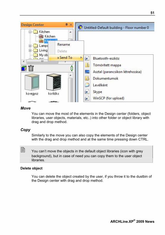
Send To… You can reach the Send To… menu – that offers special possibilities - in the Windows at file handle. The list of menu points belonging to Send to… menu depends on that in Windows system, which applications installed the Send commands to the file shortcut menu. Some typical possibilities for sending: : Desktop (create shortcut), Documents, Mail Recipient, Skype, Compressed (zipped) Folder.
CadLine
51
Move You can move the most of the elements in the Design center (folders, object libraries, user objects, materials, etc..) into other folder or object library with drag and drop method.
Copy Similarly to the move you can also copy the elements of the Design center with the drag and drop method and at the same time pressing down CTRL.
You can’t move the objects in the default object libraries (icon with grey background), but in case of need you can copy them to the user object libraries.
Delete object You can delete the object created by the user, if you throw it to the dustbin of the Design center with drag and drop method.
ARCHLine.XP® 2009 News

52
CadLine
10. Drawing recovery manager
Introduction ARCHLine.XP® gives an efficient helping hand to search former projects and drawings on the hard disks of the computer. You can use it simply, just determine the search position and conditions then you just have to select the proper one from the found projects or drawings. This function can be used excellently for searching former used works or their backup copies.
Use drawing recovery function You can reach the Drawing Recovery Manager from the Tools menu – Accessories submenu or using the File menu – New project – Search icon.
In the appearing dialog window determine, where you want to search and give the name of the file you are looking for, and the type of the file:

53
Project / Drawing
You can set what and where you are looking for. Select the proper option.
Folder Here can be seen that access path, where the program is searching. Click on the Browse button, you can select another folder or driver. The searching happens in all subfolder too.
Search for Here you can determine the name of the file or the part of it, which you want to search for. For example, if you look for the original „klimahaus.pro” file, it is enough to write in the „klima” search condition. After clicking on the Search
ARCHLine.XP® 2009 News

54
CadLine
button the program is searching files in the given path that contain the „klima” detail.
Search results You can fine the search results. In course of searching the ARCHLine.XP® search not only among the saved projects according to the given conditions, but among the backup copies (PR$ extend files) and the automatically exist archives (Archive folder) as well. Select the proper option from the drop down list, if it is necessary.
Project contents
In this field you can select one design, which is in the selected project.
Preview It shows the preview of the selected drawing from project contents list in miniature form.
File info The program represents essential information from the selected file.
Open You can open the selected project or drawing, if you click on the Open button.
You can interrupt searching with pressing down the ESC button.

55
ARCHLine.XP® 2009 News
11. Quick View Toolbar
In the ARCHLine.XP® 2009 version you can easily and simply look over the drawings in the project owing to the quick view toolbar. Besides you can change between the drawings. We recommend using the command, when you use the Windows menu – Magnify function, so only the contents of one window appear on the drawing area.
Use
Start the Quick view toolbar by clicking on the button in Status line. The open drawings in the project are represented in the appearing window.

56
After opening the Quick view toolbar window, click on a miniature, then the miniature drawing will be active.
Always show The Always show button controls the appearance of the Quick view toolbar window. If the option is switched on, then the Quick view toolbar window is visible till you don’t click on the Close button in the right upper corner /button/. If it is switched off, then the window is visible till you don’t activate another drawing.
Update The Update button updates the miniature pictures of Quick view toolbar window according to the actual status.
Multi row You can set the representation of the miniatures with the Multi row button. If it is switched off the program arranges them next to each other in a row. If it is switched on the miniatures appear in one or multi row according to the size of the Quick view toolbar window.
CadLine

57
ARCHLine.XP® 2009 News
If some screens are connected to the computer and the Dual setting is used, you can replace the Quick view toolbar window to the other screen, similarly to the Toolbar, so it increases the size of the drawing area.

58
CadLine
12. Building volume control
Introduction In ARCHLine.XP® 2009 there is a possibility to determine the volume of the building in visual form. In big densely populated towns with thick built-up areas it is important to maximize the volume of the building according to the regulations. In ARCHLine.XP® 2009 you can determine the biggest floor space available for the building, on the base of this the biggest volume, which is suitable for the local building up regulations ( like maximum height and solar access) can be determined in a simple way.
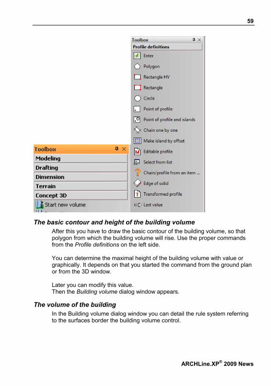
12.1. How to use You can start with Concept 3D - Start new volume icon in the Toolbox. You can use the command in the 2D window and 3D window too.
59
The basic contour and height of the building volume After this you have to draw the basic contour of the building volume, so that polygon from which the building volume will rise. Use the proper commands from the Profile definitions on the left side. You can determine the maximal height of the building volume with value or graphically. It depends on that you started the command from the ground plan or from the 3D window. Later you can modify this value. Then the Building volume dialog window appears.
The volume of the building In the Building volume dialog window you can detail the rule system referring to the surfaces border the building volume control.
ARCHLine.XP® 2009 News

60
Changeable parameters The explaining picture helps to understand the meaning of changeable parameters.
A The angle of selected plane compared to perpendicular. You can determine the angle value between 0 and 89 degree. In case of giving not a proper value, the field’s color will be red. The given angle counts from the line determined in B.
B The forehead height of the selected side: If you use this option, the C option can’t be reached.
C Shifting the starting line of oblique limiting on the base plan: If you use this option, the B option is not definable.
D Inside perpendicular limit: You can use the option independently. You can determine with its help such building volume limits, which can’t be definable in any other way.
E The maximum height of the building volume: Here you can see and modify the value of height determined at building volume base contour.
CadLine

61
ARCHLine.XP® 2009 News
For all sides Switching the option all sides of the refreshed volume model change according to the selected A-B-C-D-E values.
Information list These information help to get a picture continuously from the designing volume model according to the geometry information.
Select sides The sides of the polygon by creating base contour determine the sides of the volume model, which is lifted out from this. You can see the simplified plan of the volume model in the top view window. The selected side appears as a grey area. You can select between the sides with the button above the window. The numerical value shows how much sides exist and which one is selected now. 8/8 means, that there are 8 sides and the last one is selected. You can also select in the window if you click on the proper side.
Pre-view You can look at the changes during the drawing in the pre-view window. Each new change in the drawing can be transformed to the Pre-view window by clicking on the Update button.
Internal cuttings If you use the internal cuttings, you can graphically determine complex rules. In the appearing dialog window you can determine detailed limits on the selected side. You can make a new rule with the Insert new button, so even periodic structures can be determined. The explaining figure helps with determine different rules and you can follow the changes on the actual volume model as well by clicking on the Update button.
Changeable parameters
A The angle of the new cutting compared to perpendicular. B The base height of the new cutting compared to the base line of the selected
side. After the changing the C value is refreshed automatically. C The value of shifting the base line of the new cutting plane compared to the
base line. After the changing the B value is refreshed automatically. D The depth of the new cutting compared to the perpendicular plane of baseline. F The left side base plane of the new cutting. The limiting surface of the two
sides vertical cutting is perpendicular to the vertical plane of the base line. G The width of the new cutting. This value determines also the place of the
perpendicular limiting on the right side.

62
12.2. Editing volume model According to the preferences the volume model is ready, and it appears in the 3D window. You can modify or edit the volume model, if you click on the model with right mouse button and select the Continue definition command from the shortcut menu. After this the former window appears where you can continue fining of the rules.
CadLine

63
ARCHLine.XP® 2009 News

64
CadLine
13. Solar access protection
Introduction The ARCHLine.XP® 2009 provides a great opportunity to survey the solar access of the building or its rooms. The advantage of the function is that it is prepared in clear graphical form, which is easy to survey and with its help we can support the proper solar access of the designed building’s room. In case of not proper solar access (because of the parameters of the building or the place), you can make a decision easily about modifications according to the prepared model. Further advantage is that you can use the Solar access in any phase of designing. So you can prepare the building with equal efficiency on the volume model, on the sketch plan or on the authorization plan and on the working draw.
13.1. Information Before using the solar access, shadow analysis functions, it’s worth knowing certain rules and features.

65
Calculation basis on 3D model The shadow graphic is prepared according to the information of actual 3D model of the project. It’s important now to mention, that the ARCHLine.XP® can represent and hide certain parts of the model according to the user settings. Before using the solar access function it’s worth making sure, that the 3D model has all the information or you have to refresh it with other settings.
Appearance The appearing of the solar access depends on the set representation features. You can represent colored or black sketch depending on that you need spectacular or technical draw.
13.2. How to use Before use you have to activate the 3D model window, in which you want to prepare the solar access analysis. It’s important, that you can make the solar access analysis draw only in the 3D window. Because of the complexity of the calculation, the drawing doesn’t follow the model changing, and the changing of the 3D model view. So it’s worth setting in advance the 3D view, before the solar access analysis. Start the shadow analysis with the Add-On menu – Animation – Solar access command.
ARCHLine.XP® 2009 News

66
Then the Shadow analysis window appears where you can determine the sun position, north direction and preferences of the created graphic, for example: Shadow, Shade, and Contour. Follow these instructions step by step:
Location, date, north You can determine the location, date and north, which is important for the shadow analysis
Time setting The shadow analysis will be finished according to the here determined Start- and finish point and step.
CadLine

67
Line type on not exact hour You can determine, that the shadow contours between whole hours (for example 08:00 and 09:00) which line type will draw, if it is needed according to the interval time.
Set name for time text When the shadow analysis is finished, on the shadow contours time points appear belonging to it for easier identification. You can select the set name for time text.
Contour It determines the layer of the shadow’s contour.
Shadow hatch background colors You can determine even two different hatch backgrounds. The first color is the starting, while the second will be the finishing color. If you determine two different colors the program makes transition between the first and last color.
Hatch properties Set the shadow and the hatch properties.
On the example draw we used the Shadow with contour lines + hatches options, and in the Hatch properties window the Solid and Transparency option is switched on.
Shading Because of the complex counting method of the function it is offered to use the hidden lines.
ARCHLine.XP® 2009 News

68
Types to color Select those types of elements (wall, roof…) where the shadow appears.
Types for making shadow Select those types of element (wall, roof…) which throw a shadow. Limiting the two groups you can reduce the time consuming process of shadow analysis in case of a mass model.
Shadow receiving surfaces In the Shadowing or shading dialog window you can select the Shadow on selected surfaces only option. If you switch it off, the program prepares the shadow analysis on all surfaces of the model, which can take long time in a case of a complex model. If you switch the option on, then the program considers only the surfaces selected by the user. Select this option, if the shadow receiving surfaces are easily determined and their number is low.
Face limit
Switching on the option if the face number of the model is higher than the selected face number, the limitation is executed. It means that only the element with the selected face number is created.
Creating shadow analysis After clicking on OK in the Shadow analysis dialog window, and selecting the shadow receiving surfaces (if the option is switched on), begins the shadow analysis and the process mark of the program informs about its actual state. (You can interrupt the counting by pressing the ESC.)
CadLine

69
ARCHLine.XP® 2009 News

70
14. Symbol at line end points
Introduction With ARCHLine.XP® 2009 it is possible to place symbols at end points of certain types of elements. Symbols can be placed at end pof the following element types:
oints
ne
tic arc
Symbols can be placed at end points
Line Polyli Arc Ellip Spline
of elements in the 2D window. Placing symbols at end points in the 3D window is available only for those elements that were created with switched off work plane status.
14.1. Settings of line endings The properties of the above mentioned element types are extended with Symbol at line start point and Symbol at line end point groups.
Symbol enabled Here you can enable the representation of symbol at each line ending.
Symbol name Here you can select the symbol to be represented.
CadLine

71
By default, you can select a symbol from the Groups – Line endings – Arrowheads in the design center. The reference points (hot spots) of the arrowheads found here are defined to the top and the base.
Adjust symbol to line direction With this option it is possible to adjust the symbol to the line direction. This means that the direction of the line defined by the two reference points of the symbol is adjusted to the direction of the line. If you switch off this option, the symbol will be placed with its default direction. The end of the line is adjusted to the selected hot spot of the symbol in both cases.
ARCHLine.XP® 2009 News

72
Scale The scale of the symbol can be specified here.
Exchange endings With this option you can exchange the settings specified for Symbol at line start point with the settings specified for Symbol at line end point.
14.2. Customized arrowhead symbols If you do not find the appropriate ending in the design center, you can define your own arrowhead as follows:
• Draw the symbol with lines and hatches. • Create a group (Tools/Create group in library). Define
the top of the arrowhead symbol as the first reference point, and then define the middle point of the base of the arrowhead symbol as the second reference point.
! For these groups you have to define exactly two reference points.
• Select a line and enable the symbol in the Symbol at line start point settings through the property manager. Specify the symbol name: search and select the group you created previously.
• Modify the size of the symbol by the Scale property, if necessary.
CadLine

73
ARCHLine.XP® 2009 News
15. Replacing of groups or object
Introduction ARCHLine.XP® 2009 makes the replacement of 2D groups and 3D objects found in projects easier and more effective. With the replacement of identical elements it is possible to replace groups, and objects identical with the selected one with another one. During the design work it can easily happen that you need the replacement of the previously designed furniture elements of a bathroom or a living room. In that case the Replace group function gives you an effective help.
15.1. How to use The function is available in the Tools menu – Group options – Replace group.
The function works as follows:
74
CadLine
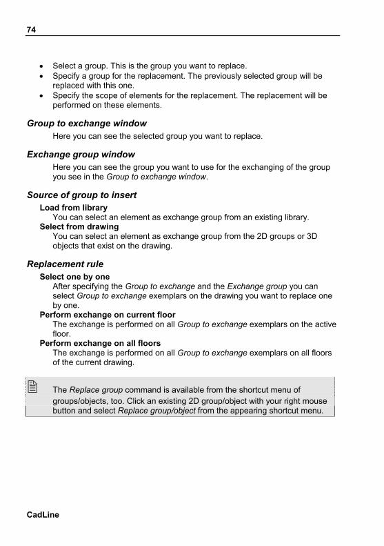
• Select a group. This is the group you want to replace. • Specify a group for the replacement. The previously selected group will be
replaced with this one. • Specify the scope of elements for the replacement. The replacement will be
performed on these elements.
Group to exchange window Here you can see the selected group you want to replace.
Exchange group window Here you can see the group you want to use for the exchanging of the group you see in the Group to exchange window.
Source of group to insert Load from library
You can select an element as exchange group from an existing library. Select from drawing
You can select an element as exchange group from the 2D groups or 3D objects that exist on the drawing.
Replacement rule Select one by one
After specifying the Group to exchange and the Exchange group you can select Group to exchange exemplars on the drawing you want to replace one by one.
Perform exchange on current floor The exchange is performed on all Group to exchange exemplars on the active floor.
Perform exchange on all floors The exchange is performed on all Group to exchange exemplars on all floors of the current drawing.
The Replace group command is available from the shortcut menu of groups/objects, too. Click an existing 2D group/object with your right mouse button and select Replace group/object from the appearing shortcut menu.
75
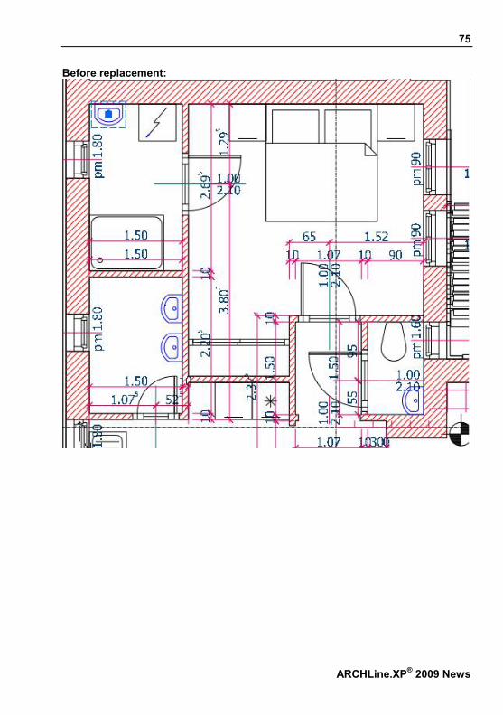
Before replacement:
ARCHLine.XP® 2009 News

76
After replacement:
CadLine

77
ARCHLine.XP® 2009 News
16. Plot layout developments
Introduction The plot layout developments made in ARCHLine.XP® 2009 ensures more comfortable and flexible editing when you place drawing parts with different scale. After paste it is possible to edit the boundary of the drawing parts. During the design work you may need to extend a previously placed drawing part; or to the contrary, you should cut it. This situation can be handled easier by the new plot layout functions. The command is available in the Plot layout menu – Edit after paste.
How to use Assuming that you have a previously created plot layout:

78
• Select a part of the drawing with the Plot layout menu – Copy with rectangle/polygon command.
• Make the appropriate plot layout window active and then place the previously selected drawing part with the Plot layout menu – Paste – Scale factor command.
• Select the Plot layout menu – Edit after paste command and select the previously placed drawing part. You can also find this command in the shortcut menu of the drawing part.
• Modify the contour with the Profile definitions commands that appear on the left, and then press Enter. The drawing part is represented on the plot layout with its modified contour:
If the content of the drawing part was changed between the time of placing and the time of its contour modification, the up-to-date state of the drawing part appears after the execution of the command.
CadLine
79
ARCHLine.XP® 2009 News
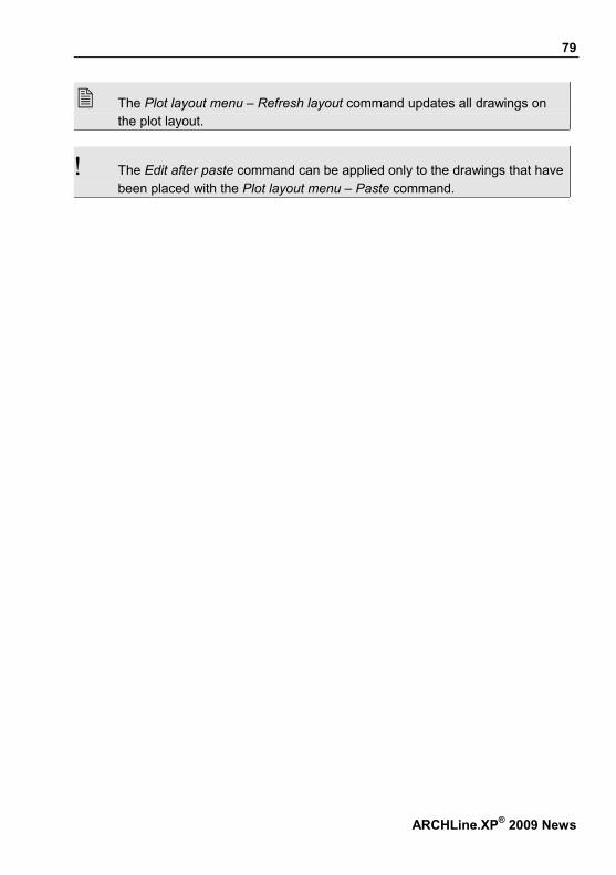
The Plot layout menu – Refresh layout command updates all drawings on the plot layout.
! The Edit after paste command can be applied only to the drawings that have been placed with the Plot layout menu – Paste command.

80
CadLine
17. Picture on wall
Introduction With the Picture on wall function of ARCHLine.XP® it is easy to put pictures on different surfaces of interior spaces. The Picture on wall is a dynamic object that can be configured with its parameters in a few steps. The Picture on wall is always based on an image which is supplemented with matting as rag mats, or collage mats and frame. Once the image is framed and displayed matting helps separate the photograph from its surroundings. It gives it its own unique space and presence. The command is available in the Modeling toolbox - Object – Picture on wall icon.
17.1. Properties In the Picture on wall property settings dialog you can specify the how the element should look on the floor-plan and in 3D views. For this you have to

81
click on Modeling menu - Object – Picture on wall or Toolbox - Object – Picture on wall icon A Picture on wall consists of three parts, as it is shown on the figure below (with the main properties):
Frame Profile Material
Image Material; Width; Height
Matting Width; Color
The total width and height depend on the dimensions of the above mentioned parts.
Visualization In this property group you can set the line representation. The following properties can be set: Color, Layer, Line width, Line type, Priority
Parameters of placement Relative height
The height of the bottom left point of the picture object relative to the zero level of the active floor.
Image parameters Material
You can select a material from the material manager dialog. This material will be the image. The program recognizes the width and height parameters of the selected material texture automatically, and their values appear in the Width and Height input fields.
Width You can modify the width of the image. This width parameter belongs to the image and not to the whole picture object.
Height You can modify the height of the image. This height parameter belongs to the image and not to the whole picture object.
Keep aspect ratio With this option the original width/height ratio of the image can be kept.
ARCHLine.XP® 2009 News

82
Frame parameters You can specify the profile of the frame around the picture along with its material.
Matting parameters You can specify the properties of the stripe between the picture frame and the border of the image.
Enabled With this option you can switch on the matting.
Width The value specified here is the width of the stripe between the picture frame and the border of the image.
Color The matting is represented with this color.
CadLine

83
The materials increase with new category: Paintings.
17.2. Placing Picture on wall • Select Modeling menu - Object – Picture on wall or the Modeling toolbox –
Object – Picture on wall command. • Set the appropriate properties and then press Ok.
In 2D • Place the picture object on the floor-plan.
Use the Graphic keyword if you want to rotate the object during the placement.
In 3D • Move your mouse to the appropriate surface and then select it. • Move the picture object to the appropriate position and then placed it.
ARCHLine.XP® 2009 News

84
CadLine
18. Elevation shadow
You can define elevation shadow by two ways: Vectorial elevation shadow Image elevation shadow
18.1. Vectorial elevation shadow In ARCHLine.XP® 2009 version the quality of vectorial elevation shadow is improved. The steps of defining vectorial elevation shadow are the following:
• Activate the 3D drawing window. Set it frontal view. • Click on the 3D View toolbar - Shadows icon. • Select the Elevation shadow.
• Copy the drawing to a 2D window with the Edit menu – Copy/Paste command. • In the 2D window you can add dimensions, annotations to the facade.

85
In case of complex facades takes long time to prepare the elevation shadow.
18.2. Image elevation shadow There is a possibility to make elevation shadow in the image window.
This method creates high precision shadow just a second. Attention: the result is an image, so you can’t add dimension and annotations. In ARCHLine.XP® 2009 this problem is resolved as following:
• Activate the 3D drawing window where you have the facade of the model without shadow.
ARCHLine.XP® 2009 News

86
• Copy the drawing into a 2D window (2D Elevation shadow) with Edit menu-Copy/Paste command.
• Activate the 3D frontal view image window of the model:
• Use the View menu – View properties – Elevation shadow command.
CadLine

87
• Click on the Edit menu – Copy bitmap to clipboard command. • Determine the resolution of image. If you select large resolution, the size of
the project will grow remarkably. We suggest the 1024 and .jpg format.
ARCHLine.XP® 2009 News

88
• Click on the Edit menu – Paste bitmap from clipboard command. • Place the image in 2D Elevation shadow window next to the previous copied
facade drawing.
CadLine

89
• Enlarge the image to the proper size and place it to the drawing. Here suggested the Add-On menu - Raster Image Calibration – Calibrate raster fast command, with its help you can make it in one step.
• Here you can add dimensions, annotations to the facade
You can also use this method to prepare wall views, colored floor plans, not just in case of Elevation shadow.
ARCHLine.XP® 2009 News

90
CadLine
19. Others
19.1. Window selection tabs Introduction
In ARCHLine.XP® 2009 the window selection tabs help the better overview and easier handling of windows in the project.
19.1.1. How to use The window selection tabs can be enabled or disabled in the File menu – Preferences – General – Toolbox settings dialog with the Show window selection tabs option. The window selection tabs can be seen on the top of the drawing area. Window selection tabs are available with magnified window and with multi-window arrangement settings, too.

91
Appearance
On each window selection tab you can read the main data of the belonging drawing window. For example in case of floor-plan drawing windows you can read the name of the window, the name of the active building and the active floor. In case of 3D windows you can read the name of the window, the name of the view and the window type (Drawing/Image).
Switching between tabs Window selection tabs make easy to switch between active windows in the project. Click the tab of the drawing you want to activate and the appropriate drawing will be active.
Tab ordering You can change the ordering of the tabs with the drag & drop method. By default, the ordering of the window selection tabs follows the order in which the windows were created. If you want to relocate a tab – and thus change the order of tabs – just drag & drop the tab to the desired position. During the relocation you can follow the actual position.
Scrolling
If there are a lot of active drawings in the project, it can happen that there is no enough room for the window selection tabs. In that case two arrows appear
ARCHLine.XP® 2009 News

92
on the right beside the tabs. With the help of these you can scroll the tabs to the left or right. For continuous scrolling, keep the one of the arrows pressed.
Drop down menu On the right side of the window selection tabs bar you can find a black arrow pointing down. This is a drop down menu from where you can choose from the entire list of the active drawings. It is practical to use it when you have many drawings.
Closing a tab A window selection tab can be closed - and thus its drawing can be put into not visible state - by the Close button on the right side of the window selection tabs bar. Later you can activate it again in the File menu – Project properties dialog.
19.2. Switching the reference line of walls Wall is placed along its reference line on the left, right or in the middle. Afterwards reference lines on the left or right can be exchanged.
Usage Before using the command it’s worth to switch on the Visibility of sides in Wall global properties window. Select the Structure -Switch the reference line command from the appearing
wall shortcut menu. You can choose more wall to change the reference line. In the property grid you can change also the reference line of the selected
wall. Here click on the Switch reference line option.
CadLine

93
The command exchanges the reference line of the wall without changing the position of the wall.
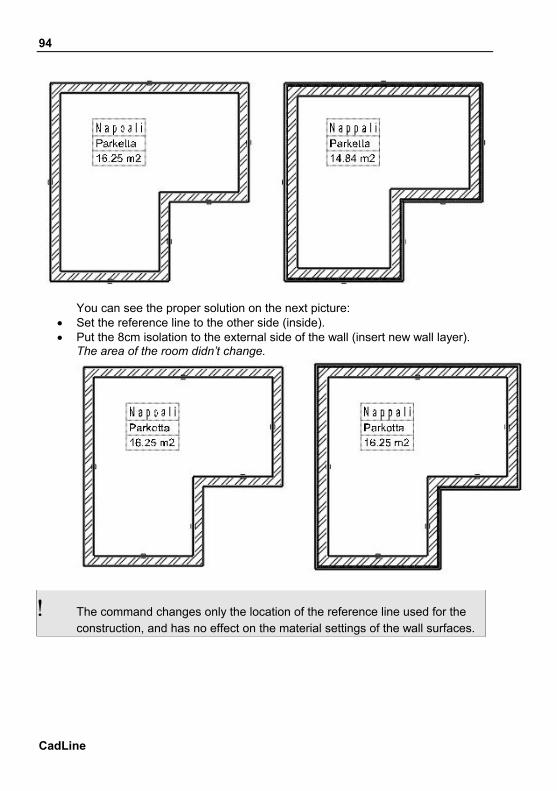
Example: In the following case the usage of the command is very important. We placed the 25cm walls with external reference line as you see on the figure. Exercise: You have to complete with 8 cm isolation on the external side of the wall. If we replace the new layer to the external side of the wall by keeping the original reference line, the brick layer of the wall is shifted, so the area of the room decrease. You can see on the picture that the 16.25 m2 decreased to 14.84 m2.
ARCHLine.XP® 2009 News
94
You can see the proper solution on the next picture:
• Set the reference line to the other side (inside). • Put the 8cm isolation to the external side of the wall (insert new wall layer).
The area of the room didn’t change.
! The command changes only the location of the reference line used for the construction, and has no effect on the material settings of the wall surfaces.
CadLine

95
19.3. Object selection Markers that appear at object selection show the reference points defined at object creation, too.
19.4. Status bar The Status bar can be switched off so you can increase the drawing area:
The Show status bar option is available in the File menu – Preferences – General – Toolbox settings tab.
19.5. Bending wall layers in case of reveal The line properties of wall layer endings can be set in the following way:
Default representation By default, wall contours are represented by line properties that have been
specified in the Wall general properties dialog. In addition, line properties of the other side (the opposite side of the wall
reference line) and the color and line width of layer lines can be set individually.
Use layer endings The Use layer endings option is a new feature in the Layers dialog. If this option is switched on, the settings in the Layer endings column in the layer properties summary table will take effect.
ARCHLine.XP® 2009 News

96
Settings in the Layer endings column define line color and thickness applied to the specific wall layer ending representation at door/window connections and at free wall endings. Previous layer line:
color and line thickness of the previous layer line will be applied to the representation of the layer ending. Next layer line:
color and line thickness of the next layer line will be applied to the representation of the layer ending. Air hole:
There is no layer ending representation. (At door/window connections the line properties assigned to door/window will be represented.) Use hatch line:
line properties of the layer hatch will be applied to the representation of the layer ending.
CadLine

97
ARCHLine.XP® 2009 News
Explanation Always start from the reference line; the layer line in this case equals to the line type specified in the general properties of wall dialog. Let’s call it the first layer line. The second layer line equals with the layer line between the first and second wall layers, the third layer line equals with the layer line between the second and third wall layers and so on. The last layer line is the outer line of the wall (the other side).
19.6. Wall - Place Frontal View This command places on the drawing the wall facade layout with openings and tiling. The wall layout indicates the wall orientation with the four cardinal directions, commonly denoted by their initials - N, S, E, W, or the intermediate directions as north-east (NE), north-west (NW), south-west (SW), and south-east (SE).
• Select any wall in the floor plan to place its facade. • Place the facade view of the wall on the drawing. • Enter Completes the command.

98
CadLine

99
ARCHLine.XP® 2009 News

100
19.7. Backup save The extension of backup file has changed. Saving your project or drawing the actually existing file on the hard disk will be renamed to .pr$ or .as$ extension. This name conversion protects you to open the backup project file instead the real last saved project. When you need in some cases the backup file there are two possibilities to open it: rename the file: name.pr$ -> name1.pro (for example in the Windows
Explorer), or File menu – New project – Search- Drawing recovery window Search results:
CadLine

101
The following warning appears before loading the selected backup project:
Then the project is loaded.
ARCHLine.XP® 2009 News