arca technologies arca · pdf filearcaplex|horizon isdn multiplexer arca technologies arca...
TRANSCRIPT

arcaplex|Horizon
ISDN MULTIPLEXER
arca technologies arca technologies
2, Trench Road, Mallusk Technology Development Center
Belfast, BT36 4TY 545 Boylston St., 3rd Floor
Northern Ireland Boston, MA 02116, USA
T: +44 (0) 28 9084 5700 T: 001 800 375 9925
F: +44 (0) 28 9084 5701 F: 001 617 262 9484
W: www.arca-technologies.com
Revision: 1.7b Document released: 27th January 2005


TABLE OF CONTENTS
3
Introduction
5
Product Specification
7
Quick Reference Guide
9
CHAPTER 1
Installation 15
CHAPTER 2
Menu System 17
CHAPTER 3
Protocol Analyser 44
CHAPTER 4
Command Line Interface 54
CHAPTER 5
Fault Finding 146
APPENDICES
Reprogramming the FLASH Reprogramming an analogue card Default settings Pin-outs BRI power feeding Examples of number setup (ETSI protocol) Examples of number setup (National ISDN protocol) SNMP support
152 158 163 167 171 173 179 181
Glossary 183

4

INTRODUCTION
5
arcaplex|Horizon
arcaplex|Horizon allows analogue and basic rate ISDN terminals to be used with a primary rate ISDN connection. A primary rate terminal ISDN can also be connected. Basic rate interfaces (BRI) and analogue (PSTN) interfaces are provided by line cards. Up to 2 line cards can be fitted. There are 2 BRI line cards – a card with 8 S0 interfaces ( I.430 compatible) and a card with 8 U interfaces (ANSI T1.601 compatible). The analogue card has 16 analogue interfaces. The Primary rate interfaces (PRI) can be configured as S2m interfaces (i.e. E.1 G.703 compatible) or T.1 interfaces.
The manual This manual outlines how arcaplex|Horizon should be set up and how the network and terminal equipment is connected.

6

PRODUCT SPECIFICATION
7
ISDN Connections arcaplex|Horizon connects to the network via an ISDN S2m or
T.1 PRI interface acting as a terminal. arcaplex|Horizon provides up to sixteen BRI’s via line cards with 8 S0 or 8 U ports and one ISDN S2m or T.1 PRI port operating in NT mode. The BRI interfaces can optionally provide power feeding (40V, 1W for S0 ; 88V, 3W for U). LED’s indicate the operating level of each port. (1) P led to indicate physical layer and data link layer activated, (2) B led to indicate that at least one B channel is active.
Analogue (PSTN) Connections arcaplex|Horizon provides up to 32 analogue lines via line cards with 16 analogue lines. The analogue lines feature –48V feed and ringing. Tone (DTMF) and pulse dialing are supported. FSK (ETSI), FSK (Bellcore) and DTMF caller ID signalling are provided. An LED at each port indicates off-hook and ringing.
Terminal Port A V.24 port is provided allowing the connection of an ANSI (or Wyse 50) compatible terminal or PC for setting up the unit.
Ethernet Port An IEEE 802.3 ethernet port is provided for connection to a local area network. LED’s indicate (1) network present, (2) network activity.
Modem Port An optional modem port is provided to allow arcaplex|Horizon to be controlled remotely. LED’s indicate that the modem is (1) off hook / ringing, (2) connected.

PRODUCT SPECIFICATION
8
Power arcaplex|Horizon is available in mains powered and dc powered versions. The mains version accepts a voltage of 110-240V a.c (50-60Hz). The dc version accepts a voltage of –36V to –72V d.c. Maximum power consumption is 90W.
Mechanical arcaplex|Horizon is enclosed in a 2U high 19” rack case. Dimensions are approximately 9cm high x 49cm wide x 40cm deep. Weight is approximately 5Kg.
QUICK REFERENCE GUIDE
9
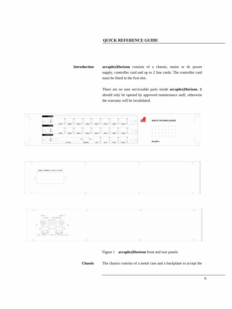
Introduction arcaplex|Horizon consists of a chassis, mains or dc power supply, controller card and up to 2 line cards. The controller card must be fitted in the first slot. There are no user serviceable parts inside arcaplex|Horizon. It should only be opened by approved maintenance staff, otherwise the warranty will be invalidated.
Figure 1 arcaplex|Horizon front and rear panels
Chassis The chassis consists of a metal case and a backplane to accept the

QUICK REFERENCE GUIDE
10
controller card, line cards and power supply.
Mains Power supply The mains power supply has a universal input suitable for 110V-240Vac/50-60Hz. Connection to any other source may result in the unit failing to comply with safety requirements. Power should be supplied via an IEC mains lead (supplied). The power supply must have a protective ground (earth). If not the mains filter will force the metal case to a voltage equal to half the mains supply voltage.
DC power supply The dc power supply has 2 input connectors. Both accept a voltage of –36V to –72V. Power can be connected to either or both input connectors. NB the 0V connections on both connectors are common and are connected to the case. The 0V connection should be connected to earth.
Figure 2 arcaplex|Horizon controller card

QUICK REFERENCE GUIDE
11
Controller card The controller card features 2 primary rate ports, 2 PC Card slots
(not used), modem (optional), LAN port, terminal port and LED’s. The terminal port is a V.24 compatible control port to which a PC or VT100 compatible terminal or a PC emulating an ANSI terminal (e.g. running Procom, Windows Terminal, Hyper terminal etc.) can be connected. The LAN port is an IEEE 802.3 compatible Ethernet port. It allows arcaplex|Horizon to be controlled remotely via Telnet. Software upgrades are possible via FTP. SNMP is also supported (see appendix). If SNMP is to be used contact arca technologies for the MIB file. The Line port is the modem (optional) which connects to an analogue telephone line. Port 1 and port 2 are the primary rate ports - PRI 1 and PRI 2. PRI 1 provides the PRI connection to a PRI line. PRI 2 provides the PRI connection to a PRI terminal equipment. Pin-outs of the terminal, ethernet, modem and PRI ports are given in an appendix. LED’s indicate power and alarm. For each primary rate port the P LED is on when both physical link layer and data link layer are active. It flashes when only the physical link is active. The B LED is on when any B channel is in use. For the Ethernet port the P LED indicates network present and the B LED indicates network activity. For the modem port the P LED is on for off-hook and flashing for

QUICK REFERENCE GUIDE
12
ringing. The B LED indicates modem connected.
Figure 3 arcaplex|Horizon U card and S card
U and S cards The U and S cards feature 8 Basic Rate Ports and LED’s. Ports 1-8 are BRI 1-8 if fitted in the first line card slot or BRI 9-16 if fitted in the second line card slot. Pin-outs of the BRI interfaces are given in an appendix. LED’s indicate power and alarm. For each port the P LED is on when both physical link layer and data link layer are active. It flashes when only the physical link is active. The B LED is on when any B channel is in use. The P and B LED’s flash alternately if the power is cut off due to an overload condition.
Figure 4 arcaplex|Horizon A card

QUICK REFERENCE GUIDE
13
A card The A card features 16 analogue (PSTN) ports and LED’s. Ports 1-16 are A1-16 if fitted in the first line card slot or A17-32 if fitted in the second line card slot. Pin-outs of the analogue interfaces are given in an appendix. For each port the LED is on when a phone is connected and off-hook. The LED flashes to indicate ringing.
Restoring default settings When the unit is first switched on the terminal port will default to 19200 baud, no parity, 8 data bits and 2 stop bits and will search for a <ctrl-c> being transmitted to arcaplex|Horizon. If this occurs arcaplex|Horizon will restore the factory defaults otherwise it will use the stored settings. If a setting has been changed and arcaplex|Horizon ceases to operate, powering up arcaplex|Horizon, while holding down <ctrl-c> for the first 20 seconds will restore a working configuration to arcaplex|Horizon. The default settings are listed in an appendix.

QUICK REFERENCE GUIDE
14

INSTALLATION
CHAPTER 1
15
Unpack arcaplex|Horizon First unpack arcaplex|Horizon and check for signs of damage in transit. If the unit or packaging is damaged this should be reported immediately to arca technologies.
Take an Inventory Assuming there is no damage, take an inventory of the parts supplied. Check that the items ordered were actually received. The list below should be of help in identifying each part. ♦ arcaplex|Horizon ISDN Multiplexer ♦ Cables for ISDN - RJ45-RJ45 (2 off) ♦ Mains Cable ♦ Terminal Cable DB9-DB9 (1 off) ♦ This Manual
Connect to a PC or terminal Plug the terminal cable into the rear of the unit and connect to a terminal or PC. (arcaplex|Horizon default terminal settings are ANSI terminal compatible, 19200 baud, 8 data bits, no parity, 2 stop bits).
Connect power Plug the power cable into the rear of the unit and switch on (arcaplex|Horizon will work on 110V or 240V mains supply without adjustment).
Configure arcaplex|Horizon Set up arcaplex|Horizon using the menus (see chapter 2 - Menu System).
Connect PRI line Plug an ISDN cable into PRI 1 (port 1 on controller card) and connect it to the network provided PRI line.
Connect terminal equipment Plug a basic rate terminal into an enabled BRI, an analogue telephone into an enabled analogue line or a primary rate terminal into PRI2 (if enabled). Make sure that the equipment is compatible with the interface it is connected to.

INSTALLATION
16
NB in the UK master sockets should be connected between the analogue connections (RJ11) and telephones.
Make calls
Try making calls from the enabled ports e.g. call the speaking clock.

MENU SYSTEM
CHAPTER 2
17
Introduction This chapter outlines the user interface of arcaplex|Horizon and how the various functions of arcaplex|Horizon are set up and used. arcaplex|Horizon has 2 user interfaces - command line interface and menu system. The menu system is described here. Details of the command line interface are provided in chapter 4 - Command Line Interface. The user interfaces operate in 2 modes - user and super. User mode only allows read access to configuration. Super mode allows read and write access. There is a facility to protect access to super mode with a password.
Power Up Screen Assuming that the hardware has been set up as described in chapter 1 – Installation, when power is applied the following message should be displayed on the user terminal or PC
Copyright Digital Engineering 1999
ISDN Multiplexer V1.3e 16 November 1999
User Mode - Type 'super' <RETURN> for write access
Command Mode - Type 'menu' <RETURN> to use menus
mux [U]>
Figure 5 arcaplex|Horizon power up display
The default data format is 19200 baud, 8 data bits, 2 stop bits, no parity. If no message appears then there is probably something wrong with the control cable. If some characters are displayed but the format is strange then the terminal parameters are probably incorrect. Try adjusting the terminal parameters so that they match arcaplex|Horizon.
MENU SYSTEM
18
arcaplex|Horizon starts with the command line interface and user mode. Type 'super' <RETURN> to change to supervisor mode. Type 'menu' <RETURN> to change to the menu system.
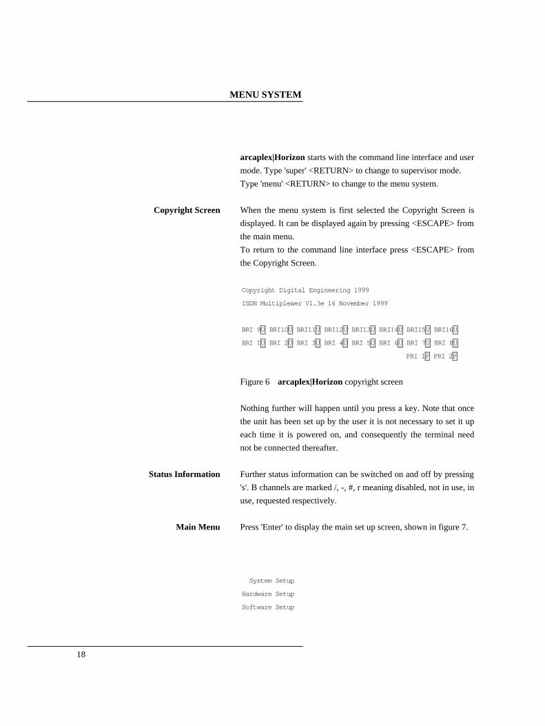
Copyright Screen When the menu system is first selected the Copyright Screen is displayed. It can be displayed again by pressing <ESCAPE> from the main menu. To return to the command line interface press <ESCAPE> from the Copyright Screen.
Copyright Digital Engineering 1999
ISDN Multiplexer V1.3e 16 November 1999
BRI 9U BRI10U BRI11U BRI12U BRI13U BRI14U BRI15U BRI16U
BRI 1U BRI 2U BRI 3U BRI 4U BRI 5U BRI 6U BRI 7U BRI 8U
PRI 1P PRI 2P
Figure 6 arcaplex|Horizon copyright screen
Nothing further will happen until you press a key. Note that once the unit has been set up by the user it is not necessary to set it up each time it is powered on, and consequently the terminal need not be connected thereafter.
Status Information Further status information can be switched on and off by pressing 's'. B channels are marked /, -, #, r meaning disabled, not in use, in use, requested respectively.
Main Menu Press 'Enter' to display the main set up screen, shown in figure 7.
System Setup
Hardware Setup
Software Setup

MENU SYSTEM
CHAPTER 2
19
Analyser Setup
Figure 7 Main System Menu
Changing Parameters The setup of arcaplex|Horizon is structured like a tree with the
menu of figure 7 at the top. The user moves to a more detailed lower function by using the <up-arrow> and <down-arrow> keys to select the desired function and presses <enter> on the keyboard. To move to the next higher function press the <esc> key on the keyboard. Note that <u> and <d> perform the same function as <up-arrow> and <down-arrow>. The <home> and <end> keys can be used to move the cursor to the first and last item in the menu if the terminal program supports them. If there is more than 1 column of items in the menu to move across the menu. <left-arrow> and <right-arrow> can also be used to display the menu for the previous and next ports in the Number Setup menu’s for individual BRI’s and analogue interfaces. Once you have located the item you wish to change use <space> or <+> and <-> to cycle through the various options permitted. Numeric values can also be altered by using <enter> and typing a new value. Use <backspace> to change to the lowest numeric value or first option. Some information must be entered by typing it in rather than using <space>, e.g. telephone numbers. Move to the item to be changed and press <enter>. A prompt will appear at the bottom of the screen requesting the information. The options listed in figure 7 are as follows.

MENU SYSTEM
20
System Setup This function allows you to set the system mode, name, password and time. There are also options to save and recall settings and restore default settings. Another option allows the FLASH to be reprogrammed for software update. Configuration of IP address (for Telnet and FTP) is also included.
Hardware Setup This function allows you to set up the communications ports, and various other hardware functions of arcaplex|Horizon.
Software Setup
This function allows you to change the operation of arcaplex|Horizon by enabling and disabling ports/channels, setting up numbers and semi-permanent connections etc.
Analyser Setup
This function allows you to operate the protocol analyser.

MENU SYSTEM
CHAPTER 2
21
System Setup Screen On selecting this option the user is presented with the screen of
figure 8. To change the fields in System Setup highlight the required field and cycle through the options using the <space>. The fields are listed below :-
System Setup
System Mode xxxx
System Name xxxx
System Password xxxx
System Time xxxx
IP Setup
Restore defaults
Save settings
Recall settings
Reprogram FLASH
Reprogram Analogue
Fig 8 System Setup Menu
System Mode This option switches arcaplex|Horizon between user and supervisor modes. A password is requested for supervisor mode unless there is no password stored. In user mode access to the menus is read only.
System Name This option allows arcaplex|Horizon to be given a name. If a name has been given it is displayed on the copyright screen and is used as the prompt for the command line user interface. The name can be up to 15 characters in length. NB Use <BACKSPACE> to delete the name.

MENU SYSTEM
22
System Password This option allows a password to be set up so that it has to be
entered before supervisor mode can be selected. It is hidden in user mode. NB Use <BACKSPACE> to delete the password.
System Time This option allows the time to be set. If a real time clock is detected a date can also be entered. This time is used for the protocol analyser.
IP Setup This option brings up a menu which allows IP addressing to be configured. 2 modes are available –auto and fixed. Auto mode means that IP address, subnet mask and gateway are configured automatically by arcaplex|Horizon by requesting values from a BOOTP or DHCP server on the network. This is the default mode. It allows arcaplex|Horizon to be used via Telnet without the user having knowledge of free IP addresses on the network. NB the automatically configured settings can be viewed using the status system command. It should be remembered that these settings may change if arcaplex|Horizon is switched off and on or disconnected from the network. Fixed mode means that IP address, subnet mask and gateway are configured in the menu. It is important to ensure that the IP address is unique. If the subnet mask is not known set it to ‘0.0.0.0’. If no gateway is to be used set it to ‘0.0.0.0’ It is generally best to use the fixed mode. Changes to IP address, subnet mask, gateway have no effect until escape is pressed.

MENU SYSTEM
CHAPTER 2
23
The menu also allows up to 3 target IP addresses for SNMP traps to be defined. More information on SNMP is given in an appendix.
Restore Defaults This option restores the factory default settings. Confirmation is requested before the settings are changed. If the saved setting for the terminal baud rate etc is different to the current setting an option to use the current terminal setting is given.
Save Settings This option saves the current settings for future recall. Confirmation is requested before the saved settings are changed. These saved settings can be recalled at any time, even if the power has been switched off and on. NB arcaplex|Horizon has 2 areas to store settings so that they are not lost on power down. 1) Current settings This area holds the current settings. It is updated when any settings change is made and is reloaded on power up. 2) Saved settings This area holds the saved settings which are saved and recalled by using this menu.
Recall Settings This option allows the saved settings to be restored. Confirmation is requested before the settings are changed. If the saved setting for the terminal baud rate etc is different to the current setting an option to use the current terminal setting is given.
Reprogram FLASH This option allows arcaplex|Horizon to be reprogrammed with new software. More details are given in an appendix.
Reprogram Analogue This option allows an arcaplex|Horizon analogue card or a DSP module on an arcaplex|Horizon analogue card to be

MENU SYSTEM
24
reprogrammed with new software. More details are given in an appendix.
System Mode supervisor / user
System Name read / set name
System Password read / set password
System Time read / set date read / set time
IP Setup read / set ip read / set target
Restore Defaults Default
Save Settings Save
Recall Settings Recall
Reprogram FLASH swl
Command line equivalents
Reprogram Analogue swl analogue

MENU SYSTEM
CHAPTER 2
25
Hardware Setup Screen On selecting this option the user is presented with the screen of
figure 9. To change the fields in Hardware Setup highlight the required field and cycle through the options using the <space>. The fields are listed below :-
Hardware Setup
Coms Port Baud Rate xxxx
Coms Port Parity xxxx
Coms Port Stop Bits xxxx
Coms Port Data Bits xxxx
Terminal type xxxx
BRI S/U Power Feed xxxx
BRI S Power Mode xxxx
BRI U Power Mode xxxx
BRI U Power Restart xxxx
BRI S Bus Timing xxxx
PRI E1/T1 Mode xxxx
PRI Equaliser xxxx
PRI E1 Mode xxxx
BRI T1 Mode xxxx
Analogue Ring Mode xxxx
Analogue Caller ID Mode xxxx
Analogue Disconnect Mode xxxx
Analogue Impedance xxxx
Analogue Start xxxx
Fig 9 Hardware Setup Menu
Coms Port Parameters These are the parameters for the control terminal i.e. baud rate,
parity, stop bits and data bits. Note that changing these parameters will mean that the user will have to change the terminal setup to

MENU SYSTEM
26
match.
Terminal Type You can select a terminal type by typing <space>. Supported terminals are ANSI, ANSI Colour and Wyse 50.
BRI S/U Power Feed Setting this to On enables power feeding to the ISDN S0-interfaces and U interfaces for any terminal adapters, ISDN telephones or NT-1's that require it.
BRI S Power Feed This field allows you to switch the power from normal mode to restricted mode, i.e. the power provided at the ISDN BRI So interface will switch polarity. This field should usually be set to Normal. Current limiters allow 25 mA per port in normal mode and 10 mA per port in restricted mode. This is equivalent to 1 W and 400 mW at 40 V. If either current limit is exceeded the power will be cut off and the P and B lights for the port will flash alternately. The power will be restarted after 10 seconds.
BRI U Power Feed Current limiters on the U interfaces allow 15 mA per port in sealing mode and 50 mA per port in normal mode. In normal mode current will cut off after 2 seconds of active current limiting off and the P and B lights for the port will flash alternately. The power will be restarted after 30 seconds if BRI U Power Restart is ser to Normal. This field should be set to sealing unless the terminal equipment is designed to be line powered.
BRI U Power Restart This field controls the restarting of U interface power feeding in normal (50mA limit) mode. If it is set to normal power is restarted after 30 seconds. If it is set to off it is not restarted.
BRI S Bus Timing In NT mode using an S interface this field will switch between adaptive timing and fixed timing on the S0 interface. Use adaptive timing if the S0 interfaces have a long cable attached.
MENU SYSTEM
CHAPTER 2
27
PRI E1/T1 Mode This field allows you to set the PRI interfaces to E1 or T1.
PRI Equaliser This field allows you to enable an equaliser on the PRI ports
which allows them to work over longer cable lengths.
PRI E1 Mode This field allows you to set the line code, framing standard and international (Si) bit usage on E1 interfaces.
PRI T1 Mode This field allows you to set the line code and framing standard on T1 interfaces. It is currently fixed as ESF/B8ZS.
Analogue Ring Mode This field allows you to set the characteristics of the ringing voltage on analogue interfaces. If it is set to Normal the ringing is 25 Hz with a dual cadence of 0.4s on, 0.4s off alternating with 0.4s on, 2s off. If it is set to USA the ringing is 20Hz with a cadence of 2s on, 4s off. If it is set to Custom then you can press enter which allows you to set the frequency (16/20/25/50 Hz) and 3 cadences. Cadence 1 is for the initial ring. Cadence 2 and Cadence 3 are alternated after the initial ring. Cadences should be entered in the form a/b where a is on time in 50ms units and b is off time in 50ms units. Set a cadence to 0/0 if it is not required. A cadence with either the on time or the off time (but not both) set to zero is invalid
Analogue Caller ID Mode This field allows you to set the format of the caller ID signal on analogue interfaces. FSK (ETSI) is for European telephones and FSK (Bellcore) is for American telephones. It can also be set to Off to disable it or DTMF. Note: Caller ID is currently disabled if Analogue Start Mode is set to Ground Start.
Analogue Disconnect Mode
This field allows you to set the change in the line state that occurs for 0.5 seconds when the network is disconnecting the call. It is
MENU SYSTEM
28
normally set to Line break but can be changed to Line reversal or Line unchanged.
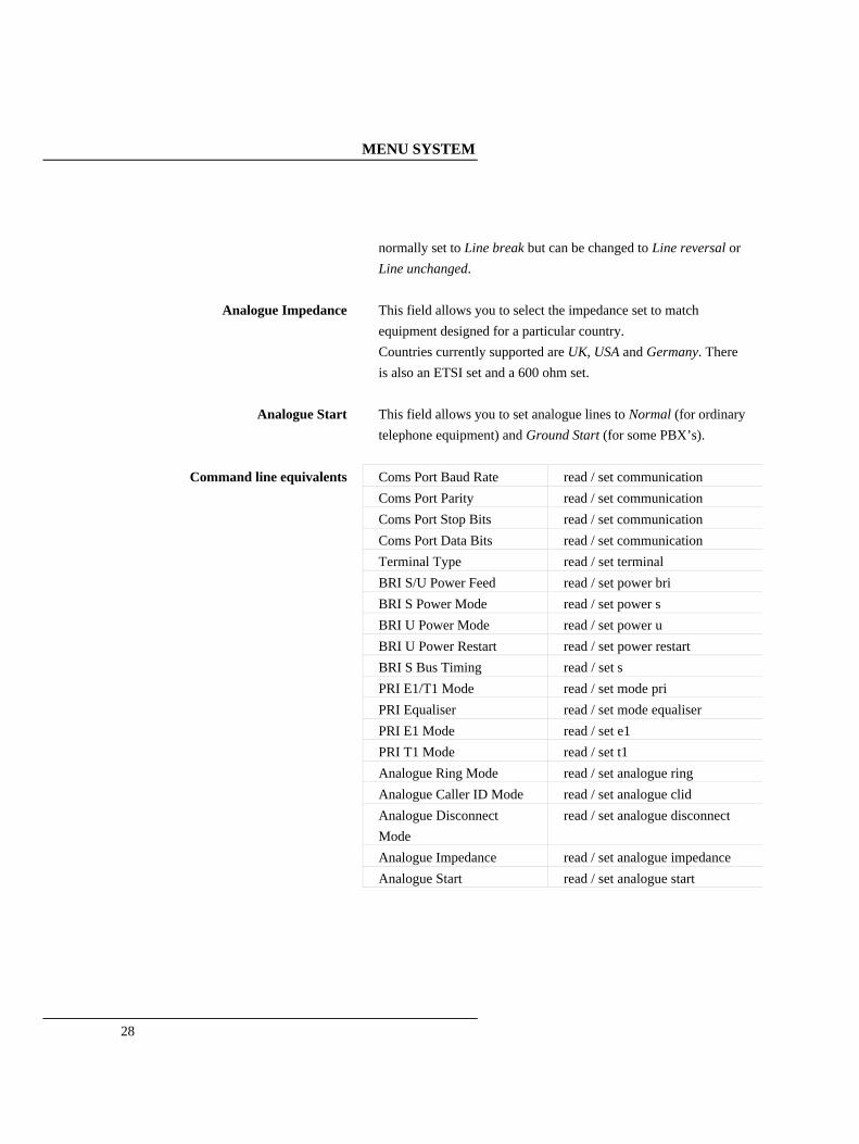
Analogue Impedance This field allows you to select the impedance set to match equipment designed for a particular country. Countries currently supported are UK, USA and Germany. There is also an ETSI set and a 600 ohm set.
Analogue Start This field allows you to set analogue lines to Normal (for ordinary telephone equipment) and Ground Start (for some PBX’s).
Coms Port Baud Rate read / set communication
Coms Port Parity read / set communication
Coms Port Stop Bits read / set communication
Coms Port Data Bits read / set communication
Terminal Type read / set terminal
BRI S/U Power Feed read / set power bri
BRI S Power Mode read / set power s
BRI U Power Mode read / set power u
BRI U Power Restart read / set power restart
BRI S Bus Timing read / set s
PRI E1/T1 Mode read / set mode pri
PRI Equaliser read / set mode equaliser
PRI E1 Mode read / set e1
PRI T1 Mode read / set t1
Analogue Ring Mode read / set analogue ring
Analogue Caller ID Mode read / set analogue clid
Analogue Disconnect Mode
read / set analogue disconnect
Analogue Impedance read / set analogue impedance
Command line equivalents
Analogue Start read / set analogue start
MENU SYSTEM
CHAPTER 2
29
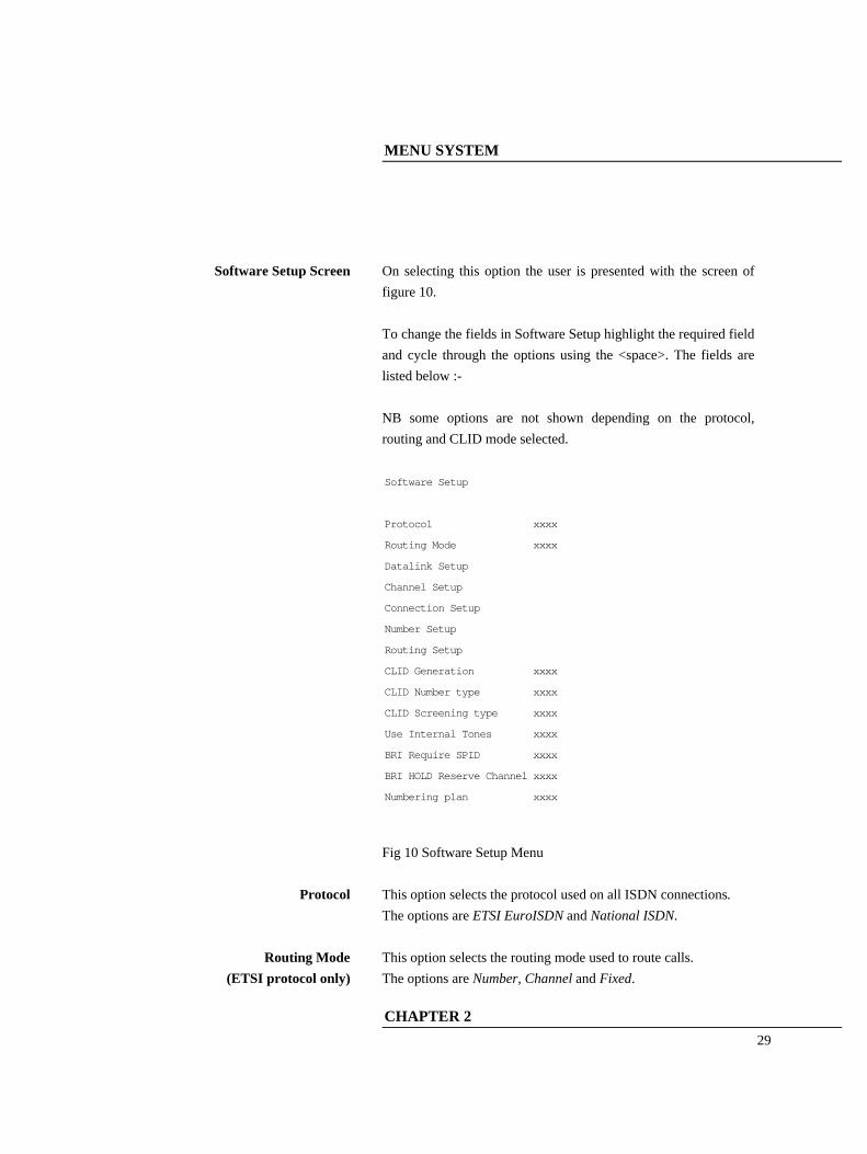
Software Setup Screen On selecting this option the user is presented with the screen of
figure 10. To change the fields in Software Setup highlight the required field and cycle through the options using the <space>. The fields are listed below :- NB some options are not shown depending on the protocol, routing and CLID mode selected.
Software Setup
Protocol xxxx
Routing Mode xxxx
Datalink Setup
Channel Setup
Connection Setup
Number Setup
Routing Setup
CLID Generation xxxx
CLID Number type xxxx
CLID Screening type xxxx
Use Internal Tones xxxx
BRI Require SPID xxxx
BRI HOLD Reserve Channel xxxx
Numbering plan xxxx
Fig 10 Software Setup Menu
Protocol This option selects the protocol used on all ISDN connections. The options are ETSI EuroISDN and National ISDN.
Routing Mode (ETSI protocol only)
This option selects the routing mode used to route calls. The options are Number, Channel and Fixed.
MENU SYSTEM
30
If it is set to number outgoing calls are routed to the first free b channel on PRI 1 and incoming calls are routed by Called Party Number to the first free B channel on a matching BRI or the first free B channel on PRI 2 if there is no match. If it is set to channel calls are routed by b channel according to the routing table (see Routing Setup). If it is set to fixed outgoing calls are routed to the first free b channel on PRI 1 and incoming calls are routed by Called Party Number to a specific B channel (see Number Setup) on a matching BRI or the first free B channel on PRI 2 if there is no match. NB in National ISDN mode outgoing calls are routed to the first free b channel on PRI 1 and incoming calls are routed by Called Party Number to the first free B channel on a matching BRI or the first free B channel on PRI 2 if there is no match.
Datalink Setup This option brings up a menu which allows the datalink mode of individual BRI's to be set up If it is set to point to point only 1 TA can be fitted on each BRI. The TA should have a fixed TEI of 0. If it is set to point to multipoint 8 TA's can be fitted on each BRI. ( with National ISDN protocol this is effectively limited to 2 since only 2 SPID's per BRI are supported ). For most terminal equipment point to multipoint should be used. For some PBX's point to point should be used.
Channel Setup This option brings up menus which allow the number of channels to be used for calls on each interface to be set up. Use the cursor keys and <ENTER> to select the interface type and then use the

MENU SYSTEM
CHAPTER 2
31
cursor keys to select the interface to be set up. Use <SPACE> to change the number of channels required. <BACKSPACE> can be used to make the number of channels 0. For primary rate interfaces the range is 0-30 for E1 and 0-23 for T1. For basic rate interfaces the range is 0-2. e.g. if the number of channels for PRI 2 is set to 6 then b1-b6 can be used for calls provided they are not assigned to semi-permanent connections. The values in Channel Setup should meet the following formula to ensure that there are enough channels on PRI 1 for all the calls that can be made. For simplicity this formula assumes no semi-permanent connections are set up on channels enabled for calls. ( no. of BRI channels enabled ) + (no. of channels enabled on PRI 2) ≤ (no. of channels enabled on PRI 1) Calls on hold release the b channel on the BRI if there is a spare channel on PRI 1 or it is the first call on hold with b channel reserve on (always on for ETSI protoco1). This ensures that calls on hold do not prevent other BRI's from having access to 2 b channels on PRI 1. NB the b channel is not released if Routing Mode is set to channel or fixed. The number of spare channels on PRI 1 is (no. of channels enabled on PRI 1) - ( no. of BRI channels enabled ) - (no. of channels enabled on PRI 2)
Connection Setup This option brings up menus which allow semi-permanent connections to be set up. Use the cursor keys and <ENTER> to select either PRI 1 or PRI 2 and then use the cursor keys to select the timeslot to be set up. Use <SPACE> to cycle through 1

MENU SYSTEM
32
channel at a time. Use <#> to cycle through 1 port at a time. Use <BACKSPACE> to set to unallocated. Connections can be made between PRI 1 and PRI 2 or any BRI. This is to allow leased line connections to be set up. Connections can also be made between PRI 2 and any BRI. This is to allow a router to be connected. The timeslot on PRI 2 assigned to the d channel (16 for E1, 24 for T1) can be can be assigned a semi-permanent connection. If this is done no calls can be made on PRI 2. If a connection clashes with another connection a '#' is displayed and the connection must be changed before another connection can be modified or the menu exited. Changes to the connections have no affect until escape is pressed to exit the connection menu.
Routing Setup This option brings up a menu which allows b channels on PRI 1 to be assigned to b channels on PRI 2 or b channels on BRI's. It is not displayed if Routing Mode is set to Number. NB The timeslots on PRI 1 and 2 assigned to the d channel (16 for E1, 24 for T1) cannot be used. Use the cursor keys to select the timeslot to be set up. Use <SPACE> to cycle through 1 channel at a time. Use <#> to cycle through 1 port at a time. Use <BACKSPACE> to set to unallocated. If a route clashes with another route a '#' is displayed and the route must be changed before another route can be modified or the menu exited.

MENU SYSTEM
CHAPTER 2
33
The relevant channels have to be enabled for calls to be made (see Channel Setup). A command line option (auto route) allows the routing table to be generated quickly based on channels enabled in Channel Setup. Changes to this menu have no affect until escape is pressed to exit it.
Number Setup (ETSI protocol) This option brings up menus which allow numbers to be assigned to the basic rate interfaces. Use the cursor keys and <ENTER> to select the number to be changed. Use <ENTER> to change the number. Use <BACKSPACE> to delete a number. 10 numbers can be set up for each basic rate interface, 5 numbers can be set up for each analogue interface and 1 number can be set up for PRI 2. The numbers used for ETSI protocol and National ISDN protocol are stored separately. The correct protocol should be selected before changing the numbers. Some examples for numbers are given in an appendix. Numbers can include ‘?’ if that digit is to be ignored in the number comparison. Numbers can also have a ‘*’ OR '+' at the end of the number if extra digits at the end of the number are to be acceptable. A subaddress can be included by adding a'#' followed by the subaddress. The subaddress can't include '?', '+' or '*'. If a subaddress only is to be stored use ?# followed by the subaddress. Numbers can have an ‘r’ at the end of the number (or

MENU SYSTEM
34
number#subaddress) if the calling party number on outgoing calls is to have the presentation indicator set to restricted. NB this applies only if CLID generation is on. The numbers in Number Setup have 2 purposes : (i) Choosing the port to send a call to. (This does not apply if Routing Mode is set to channel) This depends on the network providing a Called Party Number in the SETUP message. This can be either a full number or the last few digits. It also depends on the network routing several numbers to arcaplex|Horizon. This requires Multiple Subscriber Numbering (MSN) or Direct Dialling In (DDI) to be provided by the network. Alternatively a single number with subaddresses is acceptable. In this case the network needs to provide Called Party Subaddress as well as Called Party Number in the SETUP message. The numbers (ignoring any subaddress) are compared with the end of the Called Party Number. They should be at least as long as the part of the number that is different between each number but not longer than the Called Party Number provided by the network. If the number includes a subaddress then this is checked for an exact match with the Called Party Subaddress. If Routing Mode is set to number incoming calls are routed to the first matching BRI with a free b channel or analogue interface. If there are no matching ports they are routed to a free b channel on the PRI port. If this also fails the call is rejected. If Routing Mode is set to fixed incoming calls are routed to the first matching BRI b channel number or analogue interface. NB for BRI numbers (1) is for b1, (2) is for b2, (3)-(10) are ignored. If there are no matching ports they are routed to a free b channel on

MENU SYSTEM
CHAPTER 2
35
the PRI port. If this also fails the call is rejected. NB the number entered for PRI 2 has no effect on the routing of the call. If the matched number ends in '+' then the Called Party Number (except any extra digits) is not sent to the BRI. (ii)Calling Line Identification. This applies if CLID Generation is set to Yes. arcaplex|Horizon adds or changes the Calling Party Number in SETUP messages to the network. If there is a Calling Party Number in the SETUP message from the terminal and it matches one of the numbers for that port then it is passed through unchanged. Otherwise the first number for that port is used. If it is blank then the Calling Party Number (if any) is passed through unchanged. If it contains '?' these are replaced by '0'. If it ends in '*' or '+' the '*' or '+' is omitted. Only an exact match with the Calling Party Number is accepted by the latest software (v1.3t or later). Earlier software versions compared the stored number with the end of the Calling Party Number. If the Calling Party Number in the SETUP message from the terminal doesn't match but is no more than 5 digits and the first number for that port ends in '*' then the Calling Party Number from the SETUP message is added to the first number for that port. This is useful for PBX's where the extension number is provided as the Calling Party Number.
Number Setup (National ISDN protocol)
This option brings up menus which allow numbers to be assigned to the basic rate interfaces. Use the cursor keys and <ENTER> to

MENU SYSTEM
36
select the number to be changed. Use <ENTER> to change the number. Use <BACKSPACE> to delete a number. 2 numbers can be set up for each basic rate interface, 1 number can be set up for each analogue interface and 1 number can be set up for PRI 2. The numbers used for ETSI protocol and National ISDN protocol are stored separately. The correct protocol should be selected before changing the numbers. Some examples for numbers are given in an appendix. The match numbers in Number Setup have 2 purposes : (i) Choosing the port to send a call to. Two match numbers (a) and (b) can be set up for each BRI port. They are for 2 separate TA's or for 1 TA that uses 2 SPID's. The match numbers should be chosen from the directory numbers for the PRI line. The match number set up for the BRI TA acts as the directory number for the BRI TA. The Service Profile Identifier (SPID) for a BRI TA is equal to the match number with 0101 added. This is the generic SPID format from Bellcore National ISDN 97. NB The match numbers should all be different. Incoming calls have the Called Party Number in the SETUP message compared with the match numbers. The call is routed to the BRI TA with a matching match number. If there is no matching match number the call is routed to a free b channel on the PRI port. If this also fails the call is rejected. NB the number entered for PRI 2 has no effect on the routing of
MENU SYSTEM
CHAPTER 2
37
the call. (ii) Calling Line Identification. This applies if CLID Generation is set to Yes. arcaplex|Horizon adds or changes the Calling Party Number in SETUP messages to the network. The menu includes a CLID number for PRI 2 and match numbers for the BRI's. The match numbers also act as CLID numbers. If there is a Calling Party Number in the SETUP message from the terminal and it matches one the CLID numbers for that TA then it is passed through unchanged. Otherwise the CLID number for that TA is used. If the TA is not SPID initialised then all the CLID numbers for that port are checked. If there is no match the CLID number for the first TA is used. If it is blank then the Calling Party Number (if any) is passed through unchanged.
CLID Generation This option allows the port (PRI 2, a BRI or analogue line) from which a call is made to be detected by the network. When it is set to Yes outgoing calls have their Calling Party Number checked against the numbers in Number Setup. If it is not present it is added. If it is incorrect it is replaced.
CLID Number type (only if CLID generation on)
This option allows the choice of number type and plan in the calling party number when CLID generation is on to be configured. If it is set to Normal it is unchanged if number passed, set to unknown type / unknown plan if number changed). If it is set to National it is always set to national type / ISDN/telephony plan. NB if it is set to national the numbers in number setup should be

MENU SYSTEM
38
the national number (area code without prefix digit followed by local number)
CLID Screening type (only if CLID generation on)
This option allows the choice of screening indicator in the calling party number when CLID generation is on to be configured. If it is set to Normal it is unchanged if number passed, set to user- provided /not screened if number changed). If it is set to National it is always set to network generated
Use Internal Tones (ETSI protocol only)
This option allows the source of tones (dial, error, busy and ring) for calls to/from the basic rate ports to be selected. If it is set to No the network provided tones are used. If it is set to Yes then the internal tones for dial, error and ring are used for outgoing calls (error is also used for incoming calls on an analogue port) and the internal tone for ring is used for incoming calls. NB the ring tone for incoming calls is provided to the network. All other tones are provided to the local TA/telephone. If it is set to Auto then the internal or network provided tones are used depending on the presence of a progress indicator. NB for National ISDN protocol it is set to yes but not displayed.
BRI Require SPID (National ISDN protocol only)
This option controls how calls to/from uninitialised BRI TA's are handled. If it is set to Yes they are blocked. An uninitialised BRI TA is one that has not provided a valid SPID.
BRI HOLD Reserve Channel (National ISDN protocol only)
If this option is set to Yes one b channel on the BRI is kept free if one or more calls are on hold with no specific b channel reserved on that BRI. Hence at least one of the calls can be retrieved at all
MENU SYSTEM
CHAPTER 2
39
times. NB for ETSI protocol it is set to yes but not displayed.
Numbering plan (National ISDN protocol only)
This option sets how arcaplex|Horizon decides to stop waiting for more digits when keypad dialling is being used. This is necessary since National ISDN does not support overlap dialling on PRI lines. The dialled digits have to be stored until the whole number is received. If it is set to Unknown the number is assumed complete 10 seconds after the last digit is received. If it is set to N.America the number format is known for local, national, special and N11 numbers and the number is assumed complete after 0, 4 and 20 seconds as appropriate. Since the number format is not known for international numbers in this case the number is assumed complete 10 seconds after the last digit is received. With either setting dialling '#' after the number indicates that the number is complete. The N.America setting should be used for the countries that share the international code of '1'. These are USA, Canada, Bahamas, Barbados, Bermuda, Caribbean, Puerto Rico and US Virgin Islands. Otherwise the Unknown setting should be used.
Protocol read / set mode protocol
Routing Mode read / set mode route
Datalink Setup read / set mode bri
Channel Setup read / set channels pri read / set channels bri
Connection Setup read / set connection pri
Command line equivalents
Routing Setup read / set route

MENU SYSTEM
40
Number Setup read / set number pri read / set number bri
CLID Generation read / set mode clid
CLID Number Type read / set mode number
CLID Screening Type read / set mode screening
Use Internal Tones read / set mode tone
BRI Require SPID read / set mode spid
BRI HOLD Reserve Channel
read / set mode reserve
Numbering plan read / set mode plan

MENU SYSTEM
CHAPTER 2
41
Analyser Setup Screen On selecting this option the user is presented with the screen of
figure 11. To change the fields in Figure 7 highlight the required field and cycle through the options using the <space>. The fields are listed below :-
Analyser Setup
Layer 1 Hardware xxxx
Layer 2 Data Link xxxx
Layer 3 Call Control xxxx
Channel Filter
Call Reference Filter xxxx
Analyser Specification xxxx
Activate Analyser
Fig 11 Analyser Setup Menu
Layer 1 Hardware This option allows the reporting level for layer 1 to be selected. The options are OFF and ASCII Short Display.
Layer 2 Data Link This option allows the reporting level for layer 2 to be selected. The options are OFF, HEX Display, ASCII Short Display and ASCII Long Display.
Layer 3 Call Control This option allows the reporting level for layer 3 to be selected. The options are OFF, HEX Display, ASCII Short Display and ASCII Long Display.
MENU SYSTEM
42
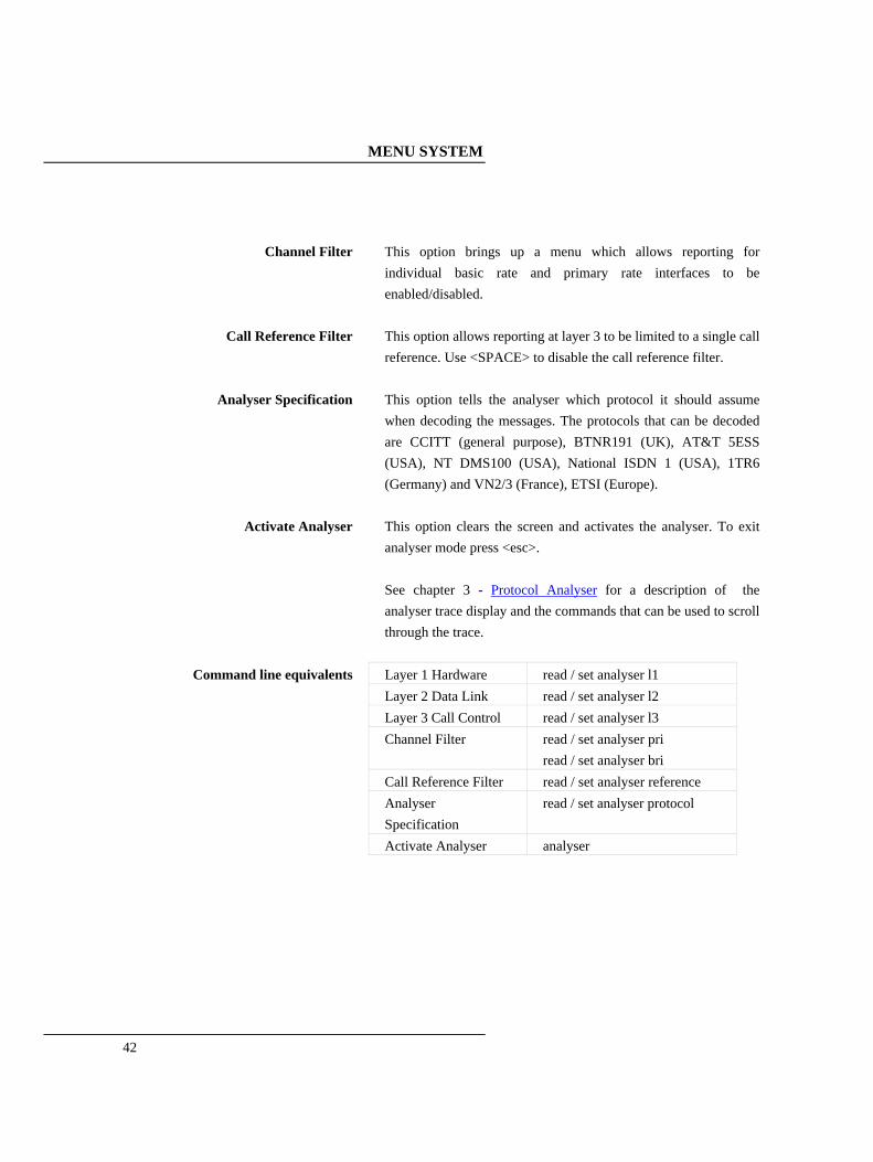
Channel Filter This option brings up a menu which allows reporting for individual basic rate and primary rate interfaces to be enabled/disabled.
Call Reference Filter This option allows reporting at layer 3 to be limited to a single call reference. Use <SPACE> to disable the call reference filter.
Analyser Specification This option tells the analyser which protocol it should assume when decoding the messages. The protocols that can be decoded are CCITT (general purpose), BTNR191 (UK), AT&T 5ESS (USA), NT DMS100 (USA), National ISDN 1 (USA), 1TR6 (Germany) and VN2/3 (France), ETSI (Europe).
Activate Analyser This option clears the screen and activates the analyser. To exit analyser mode press <esc>. See chapter 3 - Protocol Analyser for a description of the analyser trace display and the commands that can be used to scroll through the trace.
Layer 1 Hardware read / set analyser l1
Layer 2 Data Link read / set analyser l2
Layer 3 Call Control read / set analyser l3
Channel Filter read / set analyser pri read / set analyser bri
Call Reference Filter read / set analyser reference
Analyser Specification
read / set analyser protocol
Command line equivalents
Activate Analyser analyser

MENU SYSTEM
CHAPTER 2
43

PROTOCOL ANALYSER
44
Introduction The Protocol Analyser is a useful feature for checking the operation of arcaplex|Horizon. It allows the ISDN protocol on each interface to be checked. The analyser is operated using the Analyser Setup Menu (see chapter 2 - Menu System). This section describes the display of the analyser trace and the commands that can be used to scroll through the trace.
Information Provided at Layer 1 A typical display of a layer 1 message is shown below. 23: Ch BRI 1 L1 STATE= Activated
00:01:75:30.271
The information presented is outlined below. (a) Sequence Number Each message has a unique sequence number so that old messages can be easily located. (b) Channel Number The channel number (e.g.BRI 1) on which the event occurred. (c) Layer Number The layer on which the event is being reported. (d) State The new state of the physical layer e.g. Activated.

PROTOCOL ANALYSER
CHAPTER 3
45
(e) Timestamp The time that the message was recorded. The timestamp has the form dd:hh:mm:ss.nnn where dd represents days, hh hours, mm minutes, ss seconds and nnn milliseconds. Note that layer 1 messages are generated only if a change occurs in the state of the physical link.
Information Provided at Layer 2
A typical display of a short ASCII layer 2 message is shown below. 23: TA Ch BRI 2 L2 00:01:75:30.271
SAPI= 0, TEI= 40, C/R= 0, P/F=1, TYPE= SABME
The information presented is outlined below. (a) Sequence Number Each message has a unique number so that old messages can be easily located. (b) Originator This field reports which side generated the message. For PRI 1 the text is MUX for ISDN Multiplexer (arcaplex|Horizon) generated messages and NET for messages generated by the network (exchange or switch). On the other ports the text is TA for terminal generated messages and MUX for messages generated by the ISDN Multiplexer (arcaplex|Horizon). (c) Channel Number The channel number (e.g. BRI 1) on which the event occurred.
PROTOCOL ANALYSER
46
(d) Layer Number The layer on which the event is being reported. (e) Timestamp The time that the message was generated (NT message) or received (TE message). The timestamp has the form dd:hh:mm:ss.nnn where dd represents days, hh hours, mm minutes, ss seconds and nnn milliseconds. (f) Service Access Point Identifier* (g) Terminal Endpoint Identifier* (h) Command/Response Bit* (i) Poll/Final Bit* (j) Type* The message type, being one off I, RR, RNR, REJ, SABME, DM, UI, DISC, UA, FRMR, XID. A typical display of a long ASCII layer 2 message is shown below. 23: TA Ch BRI 2 L2
SAPI= 0, TEI= 40, C/R= 0, P/F=1, TYPE= INFO
N(R)= 1, N(s)= 1
The following information has been added: (k) Send Sequence Number N(s)*
PROTOCOL ANALYSER
CHAPTER 3
47
(l) Receive Sequence Number N(r)* Layer 2 management transactions may be also decoded in long form messages. A typical decode follows. 23: TA Ch BRI 2 L2 00:01:75:30.271
SAPI= 0, TEI= 40, C/R= 0, P/F=1, TYPE= UI
MEI= 15, Ri= 7FCD, MSG TYPE= ID Request, Ai= 0
The following information has been added: (m) Management Entity Identifier* (n) Reference Number (Ri)* (o) Management Message Type* One of ID Request, ID Assigned, ID Denied, ID Check Request, ID Check Response, ID Remove, ID Verify. (p) Action Indicator* Only Information and certain Unnumbered Information messages at layer 2 include layer 3 messages. Fields marked with * are explained further in CCITT Q.921 Digital Subscriber Signaling System No 1, Data Link Layer. A typical display of a hex layer 2 message is shown below. 23: TA Ch BRI 2 L2 00:01:75:30.271
02 81 00 02 41 01 81 0D 18 01 89
PROTOCOL ANALYSER
48
The information contained in the message is not decoded but simply displayed as hex octets.
Information Provided at Layer 3
A typical display of a short ASCII layer 3 message is shown below. 23: TA Ch BRI 1 L3 00:01:75:30.271
PD= 65, LEN= 1, FLAG= Orig, CALL REF= 3, TYPE= SETUP
The information presented is outlined below. (a) Sequence Number Each message has a unique sequence number so that old messages can be easily located. (b) Originator This field reports which side generated the message. For PRI 1 the text is MUX for ISDN Multiplexer (arcaplex|Horizon) generated messages and NET for messages generated by the network (exchange or switch). On the other ports the text is TA for terminal generated messages and MUX for messages generated by the ISDN Multiplexer (arcaplex|Horizon). (c) Channel Number The channel number (e.g. BRI 1) on which the event occurred. (d) Layer Number The layer on which the event is being reported.

PROTOCOL ANALYSER
CHAPTER 3
49
(e) Timestamp The time that the message was generated (NT message) or received (TE message). The timestamp has the form dd:hh:mm:ss.nnn where dd represents days, hh hours, mm minutes, ss seconds and nnn milliseconds. (f) Protocol Discriminator* (g) Call Reference* The call reference consists of three parts, the Length of the call reference, the Value of the call reference and the Originator of the call reference. (h) Message Type* One of the Q.931 supported messages, or network specific message. A typical display of a long ASCII layer 3 message is shown below. 23: TA Ch BRI 1 L3 00:01:75:30.271
PD= 65, LEN= 1, FLAG= Orig, CALL REF= 3, TYPE= SETUP
CALLING PARTY NUMBER:0 LENGTH= 7
TYPE= Unknown PLAN= ISDN/Telephony NUMBER= ‘234231’
CALLED PARTY NUMBER:0 LENGTH= 7
TYPE= Unknown PLAN= ISDN/Telephony NUMBER= ‘384020’
In the long ASCII message decode all the information elements contained in the message are decoded. Information elements are separated by a blank line, the information element name together with relevant codeset and length appears as a heading above each information element decode and the decoded information is

PROTOCOL ANALYSER
50
indented by 1 space. For more information on * marked fields, messages and information elements refer to CCITT Q.931 Digital Subscriber Signaling System No 1, Network Layer. A typical display of a hex layer 3 message is shown below. 23: TA Ch BRI 2 L2 00:01:75:30.271
41 01 81 0D 18 01 89
The information contained in the message is not decoded but simply displayed as hex octets.
PROTOCOL ANALYSER
CHAPTER 3
51
Analyser Commands
As soon as you enter analyser mode stored messages (if there are any) are displayed in accordance with the analyser options selected. You may enter <esc> to exit analyser mode, change the decode options and enter analyser mode again without losing any messages. The options available are:- (a) <m> - Manual Mode The analyser enters manual mode. Automatic display of incoming messages is stopped and the user can review the messages in the message buffer. Pressing M again will leave manual mode. (b) <home> or <b>- Go to First Message Will display messages starting at the oldest message in the buffer. This command works in manual and automatic modes. (c) <end> or <e>- Go to Last Message Will go to the last message in the buffer and display any new messages which arrive. This command works in manual and automatic modes. (d) <up> or <u> - Review Previous Message Will display the message which arrived just before the last message displayed. This command works only in manual mode. (e) <down> or <d> - Go to Next Message Will display the message which arrived just after the last message displayed. This command works only in manual mode. (f) <c> - Clear Buffer

PROTOCOL ANALYSER
52
Will remove all messages from the buffer. This command works in manual and automatic modes. (g) <h> - Pause Display Will pause a scrolling display. Pressing <h> will start the display scrolling again. Note that whenever an attempt is made to move to a message beyond the start or end of the message buffer a beep will be sent to the terminal.

PROTOCOL ANALYSER
CHAPTER 3
53

COMMAND LINE INTERFACE
54
Introduction The command line interface is an alternative user interface to the menu system. All menu items have an equivalent command. The command line interface can be accessed via the serial port, via the (optional) modem or (by using Telnet) via the Ethernet port. There are some commands that have no equivalent in the menu system. These are debug, history, test, trace, upload, the reset commands and the restart commands. As with the menu system there are 2 modes - user and super. There are many commands that can only be used in super mode. These are upload, diagnostic, swl, all set commands, all reset commands, all restart commands and read password. Some commands only apply when National ISDN protocol is selected. They are set mode reserve, set mode route, set mode spid and set mode plan. One command applies only when ETSI protocol is selected. It is set mode tone. Some commands apply only if ETSI protocol is selected and Routing Mode is set to Channel. They are set route pri and auto route. Two commands apply only if CLID generation is enabled. They are set mode number and set mode screening. Commands will not be accepted if they refer to a port that is not fitted. One command – diagnostic ise not available when using Telnet.

COMMAND LINE INTERFACE
CHAPTER 4
55
Syntax Commands are shown in full. When part of a word is in lower case only the upper case part is required. Commands are not case sensitive. Commands typed as upper case are displayed as lower case. Commands must include a space between each word. When number(s) are specified individual numbers or groups of numbers in the specified range are acceptable (no spaces allowed) e.g. 1-15 1-2,3,6-8 1,4,9 all is accepted for a number range. yes and no are accepted as pseudonyms for on and off. rem can be used at the start of a command so that it is ignored.
Read commands All set commands have an equivalent read command. This is normally the set command with set replaced by read and the last parameter omitted. e.g. set power bri on has an equivalent read command read power bri. Groups of settings can be read by a shortened form e.g. read power is equivalent to read power bri followed by read power s followed by read power u
Help commands There are help commands provided to show the syntax of every command except read commands. All set commands have an equivalent help command. This is normally the set command with set replaced by help and the last parameter omitted. e.g. set power bri on has an equivalent read command help power bri. Help on groups of set commands can be read by a shortened form

COMMAND LINE INTERFACE
56
e.g. help power is equivalent to help power bri followed by help power restart followed by help power s followed by help power u Typing help on its own gives a full list of commands.
Command rota Previous commands can be selected for use again using the up and down cursor keys. This requires terminal emulation to be set correctly.

COMMAND LINE INTERFACE
CHAPTER 4
57
List of commands analyser
auto route cls debug analogue debug bri debug pri diagnostic help commands history menu read commands recall reset system reset l1 bri reset l1 pri reset l3 analogue reset l3 bri reset l3 pri restart bri restart pri save set analogue clid set analogue disconnect set analogue impedance set analogue ring set analogue start set analyser bri set analyser l1 set analyser l2 set analyser l3 set analyser pri set analyser protocol set analyser reference set channels analogue

COMMAND LINE INTERFACE
58
set channels bri set channels pri set communication set connection pri set date set e1 set ip set mode bri set mode clid set mode protocol set mode plan set mode pri set mode reserve set mode route set mode tone set mode spid set name set number bri set number pri set password set power bri set power restart set power s set power u set route pri set s set t1 set time start l1 bri start l2 bri start l2 pri status status bri status pri status system

COMMAND LINE INTERFACE
CHAPTER 4
59
supervisor swl (software load) swl analogue trace upload user version

COMMAND LINE INTERFACE
60
ANALYSER command Clears the screen and enables protocol analyser display.
Syntax ANALYser
Examples mux [U]> analyser 3 : TA Ch BRI1 L3 00:16:14:12.173 PD= 8, LEN= 1, FLAG= Orig, CALL REF= 1 SETUP
4 : MUX Ch PRI1 L3 00:16:14:12.217
PD= 8, LEN= 2, FLAG= Orig, CALL REF= 4 SETUP
7 : NET Ch PRI1 L3 00:16:14:12.285
PD= 8, LEN= 2, FLAG= Dest, CALL REF= 4 SETUP ACKNOWLEDGE
9 : MUX Ch BRI1 L3 00:16:14:12.316
PD= 8, LEN= 1, FLAG= Dest, CALL REF= 1 SETUP ACKNOWLEDGE
Related commands set analyser l1 set analyser l2 set analyser l3 set analyser bri set analyser pri set analyser reference set analyser protocol trace
Menu Equivalent Analyser Setup - Activate Analyser

COMMAND LINE INTERFACE
CHAPTER 4
61
AUTO ROUTE
command Generates a routing table based on channel setup. (ETSI protocol only - also requires routing mode to be channel) Channels on PRI 1 are allocated to enabled channels on PRI 2 and enabled channels on BRI's in that order. Use read route pri to view the generated routing. If there are insufficient channels on PRI 1 to route to all the other enabled channels an error message is displayed and the existing routing table is unchanged.
Syntax AUto ROUte
Examples mux [S]> auto route
Related commands set mode route set route pri
Menu Equivalent None.

COMMAND LINE INTERFACE
62
CLS command Clears the terminal screen.
Syntax CLS
Examples mux [U]> cls
Related commands None.
Menu Equivalent None.
COMMAND LINE INTERFACE
CHAPTER 4
63
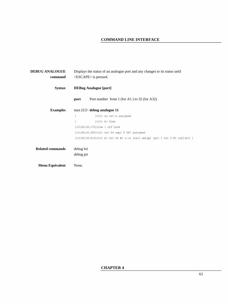
DEBUG ANALOGUE
command Displays the status of an analogue port and any changes to its status until <ESCAPE> is pressed.
Syntax DEBug Analogue [port] port Port number from 1 (for A1 ) to 32 (for A32)
Examples mux [U]> debug analogue 11 [ ]vl2: no tei's assigned
[ ]vl3: b: free
[13:28:18.175]line : off hook
[13:28:18.265]vl2: tei 64 sapi 0 TEI assigned
[13:28:18.610]vl3: b: tei 64 #1 u->n (call setup) [pri 1 tei 0 #1 ts01(b1) ]
Related commands debug bri debug pri
Menu Equivalent None.
COMMAND LINE INTERFACE
64
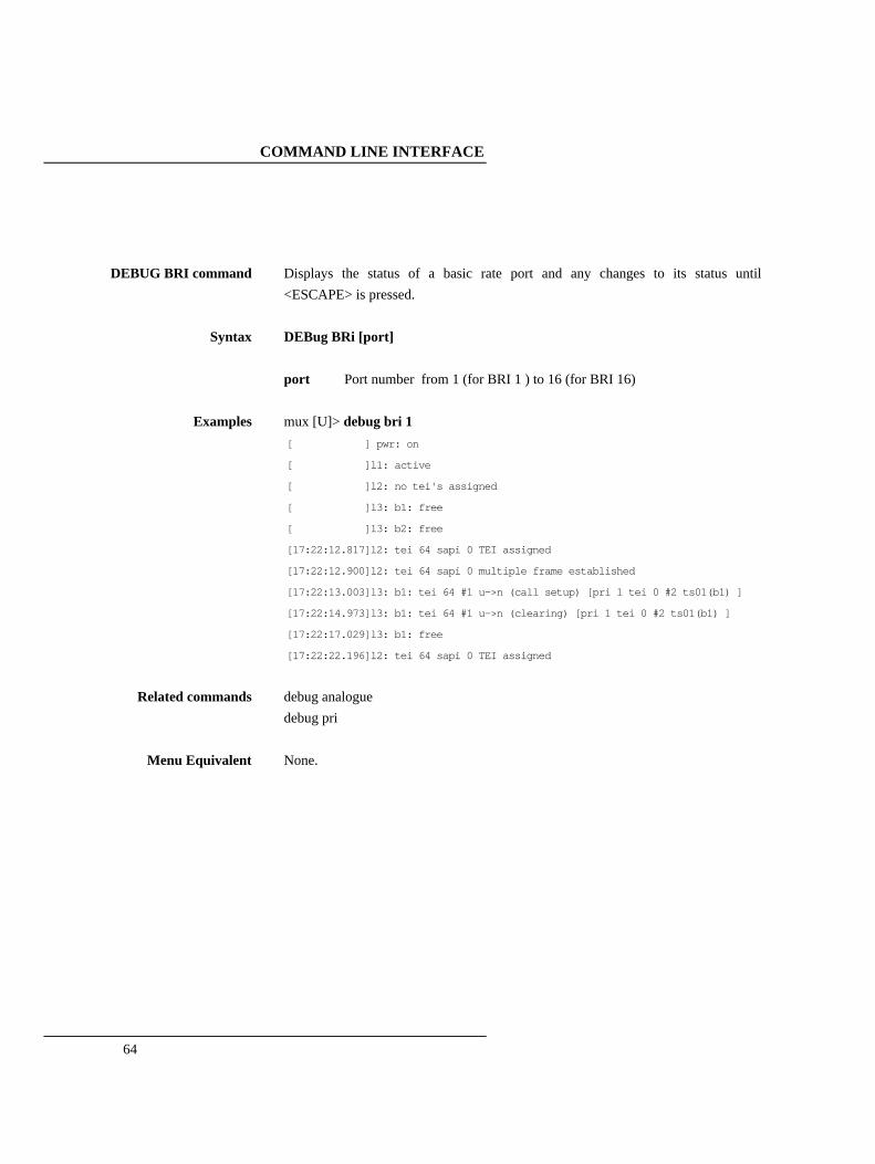
DEBUG BRI command Displays the status of a basic rate port and any changes to its status until
<ESCAPE> is pressed.
Syntax DEBug BRi [port] port Port number from 1 (for BRI 1 ) to 16 (for BRI 16)
Examples mux [U]> debug bri 1 [ ] pwr: on
[ ]l1: active
[ ]l2: no tei's assigned
[ ]l3: b1: free
[ ]l3: b2: free
[17:22:12.817]l2: tei 64 sapi 0 TEI assigned
[17:22:12.900]l2: tei 64 sapi 0 multiple frame established
[17:22:13.003]l3: b1: tei 64 #1 u->n (call setup) [pri 1 tei 0 #2 ts01(b1) ]
[17:22:14.973]l3: b1: tei 64 #1 u->n (clearing) [pri 1 tei 0 #2 ts01(b1) ]
[17:22:17.029]l3: b1: free
[17:22:22.196]l2: tei 64 sapi 0 TEI assigned
Related commands debug analogue debug pri
Menu Equivalent None.

COMMAND LINE INTERFACE
CHAPTER 4
65
DEBUG PRI command Displays the status of a primary rate port and any changes to its status until
<ESCAPE> is pressed.
Syntax DEBug PRi [port] port Port number from 1 (for PRI 1 ) to 2 (for PRI 2)
Examples mux [U]> debug pri 1 [ ]l1: active
[ ]l2: tei 0 sapi 0 multiple frame established
[ ]l3: ts01(b1) : tei 0 #1 u->n [bri 8 tei 0 #1 b1 (connected)]
[ ]l3: ts02(b2) : free
[ ]l3: ts03(b3) : semi-permanent connection to pri 2 ts01(b1)
"
"
[ ]l3: ts31(b30) : free
[17:18:05.455]l3: ts01(b1) : tei 0 #1 u->n [bri 8 tei 0 #1 b1 (clearing)]
[17:18:06.449]l3: ts01(b1) : free
[17:18:55.430]l1: not active
[17:19:00.770]l2: tei 0 sapi 0 awaiting establishment
[17:19:01.771]l2: tei 0 sapi 0 TEI assigned
[17:19:14.759]l1: active
[17:19:15.016]l2: tei 0 sapi 0 multiple frame established
Related commands debug analogue debug bri
Menu Equivalent None.
COMMAND LINE INTERFACE
66
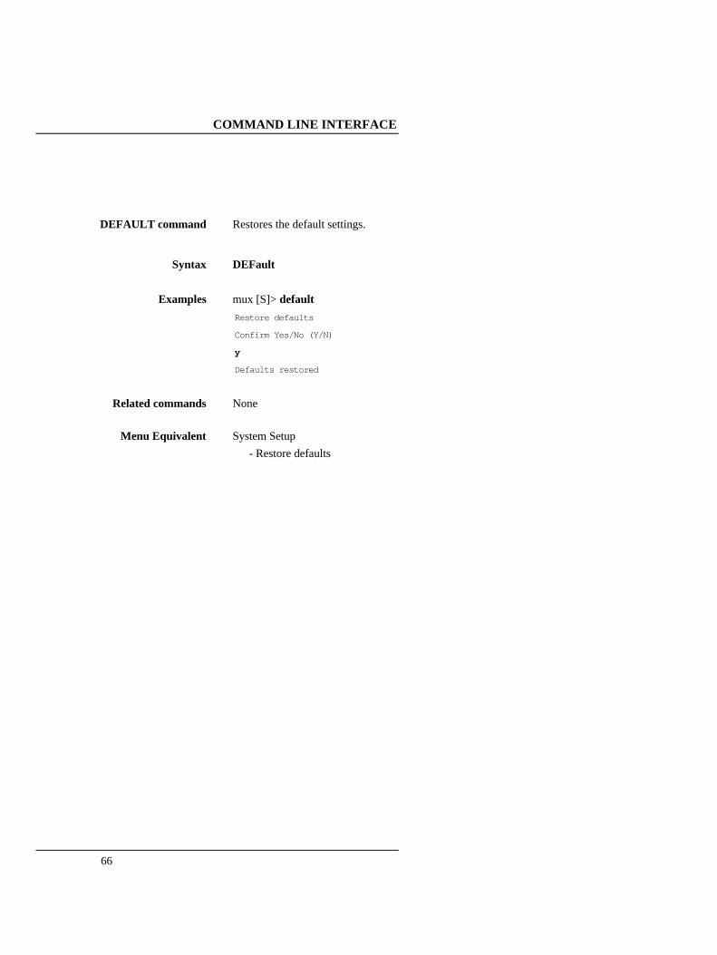
DEFAULT command Restores the default settings.
Syntax DEFault
Examples mux [S]> default Restore defaults
Confirm Yes/No (Y/N)
y
Defaults restored
Related commands None
Menu Equivalent System Setup - Restore defaults
COMMAND LINE INTERFACE
CHAPTER 4
67
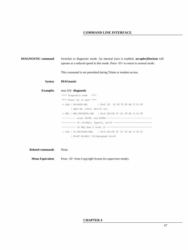
DIAGNOSTIC command Switches to diagnostic mode. An internal trace is enabled. arcaplex|Horizon will
operate at a reduced speed in this mode. Press <D> to return to normal mode. This command is not permitted during Telnet or modem access.
Syntax DIAGnostic
Examples mux [S]> diagnostic **** Diagnostic mode ****
**** Press [D] to exit ****
-> DLE | PH-DATA-IND | Ch=0 [8] FC FF 03 0F DB 13 01 FF
| SAPI=3F, C/R=0, TEI=7F <UI>
-> MDL | MDL-UNITDATA-IND | Ch=0 CEI=3F,7F [5] 0F DB 13 01 FF
----------- start 60499, end 6049d -----------------------------------
----------- UI: Ri=DB13, Type=01, Ai=7F ------------------------------
----------- ID REQ chan 0 count 10 -----------------------------------
-> DLE | DL-UNITDATA-REQ | Ch=0 CEI=3F,7F [5] 0F DB 13 02 81
| PD=0F Ri=DB13 {ID-Assigned} Ai=40
Related commands None.
Menu Equivalent Press <D> from Copyright Screen (in supervisor mode).

COMMAND LINE INTERFACE
68
HELP commands There is an equivalent help command for every command (except help and read
commands). The correct syntax for a command is shown.
Syntax HElp [text] text a command with any values omitted Help on groups of commands can be read by using a shortened form (see examples). If help is required for a set command the word set can be omitted. If text is omitted help is given on all commands.
Examples mux [U]>help set power s SEt POWer S [NORmal|RESTRicted]
mux [U]>help power s
SEt POWer S [NORmal|RESTRicted]
mux [U]>help power SEt POWer BRi [OFF|ON]
SEt POWer RESTARt [NORmal|OFF]
SEt POWer S [NORmal|RESTRicted]
SEt POWer U [SEAling|NORmal]
mux [U]>
mux [U]>help trace TRace
Related commands set commands read commands
Menu Equivalent None.
COMMAND LINE INTERFACE
CHAPTER 4
69
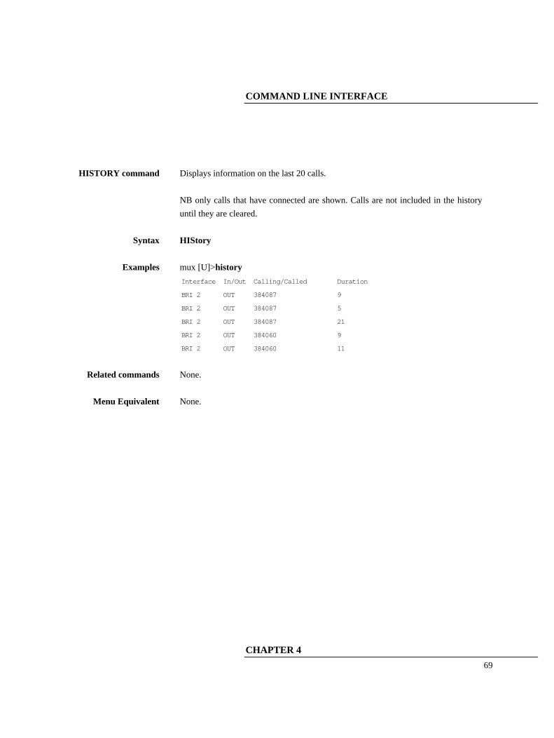
HISTORY command Displays information on the last 20 calls.
NB only calls that have connected are shown. Calls are not included in the history until they are cleared.
Syntax HIStory
Examples mux [U]>history Interface In/Out Calling/Called Duration
BRI 2 OUT 384087 9
BRI 2 OUT 384087 5
BRI 2 OUT 384087 21
BRI 2 OUT 384060 9
BRI 2 OUT 384060 11
Related commands None.
Menu Equivalent None.

COMMAND LINE INTERFACE
70
MENU command Switches from command line interface to menu system.
Press <ESCAPE> from the copyright screen to return to the command line interface.
Syntax MEnu
Examples mux [U]> menu
Related commands None
Menu Equivalent None

COMMAND LINE INTERFACE
CHAPTER 4
71
READ commands There is an equivalent read commands for every set command. The setting is
displayed in the form of a command that will make that setting.
Syntax REAd [text] text a set command with the set and the value to be set omitted Groups of settings can be read by using a shortened form (see examples).
Examples mux [U]>read power s set power s normal
mux [U]>read power set power s normal
set power u sealing
set power bri on
Related commands set commands help commands
Menu Equivalent All menus.

COMMAND LINE INTERFACE
72
RECALL command Recalls the alternate settings and stores them as the current settings.
Syntax RECall
Examples mux [S]> recall Recall settings
Confirm Yes/No (Y/N)
y
Settings recalled
Related commands save
Menu Equivalent System Setup - Recall settings
COMMAND LINE INTERFACE
CHAPTER 4
73
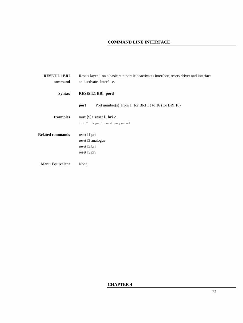
RESET L1 BRI
command Resets layer 1 on a basic rate port ie deactivates interface, resets driver and interface and activates interface.
Syntax RESEt L1 BRi [port] port Port number(s) from 1 (for BRI 1 ) to 16 (for BRI 16)
Examples mux [S]> reset l1 bri 2 bri 2: layer 1 reset requested
Related commands reset l1 pri reset l3 analogue reset l3 bri reset l3 pri
Menu Equivalent None.

COMMAND LINE INTERFACE
74
RESET L1 PRI
command Resets layer 1 on a primary rate port ie resets driver and interface.
Syntax RESEt L1 PRi [port] port Port number(s) from 1 (for PRI 1 ) to 2 (for PRI 2)
Examples mux [S]> reset l1 pri 2 pri 2: layer 1 reset requested
Related commands reset l1 bri reset l3 analogue reset l3 bri reset l3 pri
Menu Equivalent None.
COMMAND LINE INTERFACE
CHAPTER 4
75
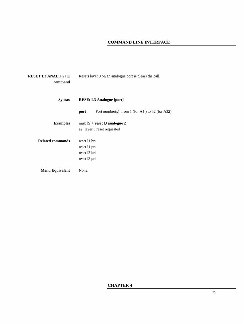
RESET L3 ANALOGUE
command
Resets layer 3 on an analogue port ie clears the call.
Syntax RESEt L3 Analogue [port] port Port number(s) from 1 (for A1 ) to 32 (for A32)
Examples mux [S]> reset l3 analogue 2 a2: layer 3 reset requested
Related commands reset l1 bri reset l1 pri reset l3 bri reset l3 pri
Menu Equivalent None.

COMMAND LINE INTERFACE
76
RESET L3 BRI command
Resets layer 3 on a basic rate port ie clears all calls. Also frees SPID's when National ISDN protocol is selected.
Syntax RESEt L3 BRi [port] port Port number(s) from 1 (for BRI 1 ) to 16 (for BRI 16)
Examples mux [S]> reset l3 bri 2 bri 2: layer 3 reset requested
Related commands reset l1 bri reset l1 pri reset l3 analogue reset l3 pri
Menu Equivalent None.

COMMAND LINE INTERFACE
CHAPTER 4
77
RESET L3 PRI
command Resets layer 3 on a primary rate port ie clears all calls.
Syntax RESEt L3 PRi [port] port Port number(s) from 1 (for PRI 1 ) to 2 (for PRI 2)
Examples mux [S]> reset l3 pri 2 pri 2: layer 3 reset requested
Related commands reset l1 bri reset l1 pri reset l3 analogue reset l3 bri
Menu Equivalent None.
COMMAND LINE INTERFACE
78
RESTART BRI
command Sends a restart message to a basic rate port. This command can only be used for point to point ports. NB if any calls are active a reset l3 bri command should be used first.
Syntax RESTArt BRi [port] port Port number(s) from 1 (for BRI 1 ) to 16 (for BRI 16)
Examples mux [S]> restart bri 1 bri 1: requesting restart message
Related commands restart pri
Menu Equivalent None.

COMMAND LINE INTERFACE
CHAPTER 4
79
RESTART PRI
command Sends a restart message to a primary rate port. NB if any calls are active a reset l3 pri command should be used first.
Syntax RESTArt PRi [port] port Port number(s) from 1 (for PRI 1 ) to 2 (for PRI 2)
Examples mux [S]> restart pri 1 pri 1: requesting restart message
Related commands restart bri
Menu Equivalent None.

COMMAND LINE INTERFACE
80
SAVE command Saves the current settings as the alternate settings.
Syntax SAve
Examples mux [S]> save Save settings Confirm Yes/No (Y/N) y Settings saved
Related commands save
Menu Equivalent System Setup - Save settings

COMMAND LINE INTERFACE
CHAPTER 4
81
SET ANALOGUE CLID
command Sets the format of the caller ID signal for analogue ports.
Syntax SEt Analogue CLid [mode] mode OFF Caller ID disabled ETSI FSK to ETSI standard BELLCore FSK to Bellcore standard DTMF DTMF
Examples mux [S]> set analogue clid etsi OK
Related commands set analogue disconnect set analogue impedance set analogue ring set analogue start
Menu Equivalent Hardware Setup - Analogue Caller ID Mode

COMMAND LINE INTERFACE
82
SET ANALOGUE
DISCONNECT command
Sets the type of line change when a call is disconnected.
Syntax SEt Analogue DISConnect [mode] mode OFF No change BREak Line break REVerse Line reversal
Examples mux [S]> set analogue disconnect break OK
Related commands set analogue clid set analogue impedance set analogue ring set analogue start
Menu Equivalent Hardware Setup - Analogue Disconnect Mode

COMMAND LINE INTERFACE
CHAPTER 4
83
SET ANALOGUE
IMPEDANCE command Sets the impedance set for analogue lines.
Syntax SEt Analogue IMPedance [mode] mode UK UK impedance set ETSI ETSI impedance set USA USA impedance set GERMANY German impedance set 600R 600 ohm impedance set
Examples mux [S]> set analogue impedance uk OK
Related commands set analogue clid set analogue disconnect set analogue ring set analogue start
Menu Equivalent Hardware Setup - Analogue Impedance

COMMAND LINE INTERFACE
84
SET ANALOGUE RING
command Sets the frequency and cadences used for ringing on analogue ports.
Syntax SEt Analogue RIng [mode] or SEt Analogue RIng CUstom [f] [c1] [c2] [c3] mode NORmal Normal (UK style) ringing USA USA style ringing f 16 16 Hz 20 20 Hz 25 25 Hz 50 50 Hz c1 initial cadence c2 cadence alternated with c3 c3 cadence alternated with c2 NB c1, c2, c3 are in the form a/b where a is on time and b is off time, both in 50ms units. Maximum values are 150 for 7.5 seconds. Use 0/0 for cadences that are not required. A cadence with either the on time or the off time (but not both) set to zero is invalid.
Examples mux [S]> set analogue ring normal OK mux [S]> set analogue ring custom 25 20/20 8/4 40/4 OK
Related commands set analogue clid set analogue disconnect set analogue impedance set analogue start
Menu Equivalent Hardware Setup - Analogue Ring Mode
COMMAND LINE INTERFACE
CHAPTER 4
85
SET ANALOGUE START command
Sets the analogue lines to use loop start or ground start.
Syntax SEt Analogue STARt [mode] mode NORmal Normal (Loop start) GROund Ground start
Examples mux [S]> set analogue start normal OK
Related commands set analogue clid set analogue disconnect set analogue impedance set analogue ring
Menu Equivalent Hardware Setup - Analogue Start
COMMAND LINE INTERFACE
86
SET ANALYSER BRI command
Enables/disables analyser display for a basic rate port
Syntax SEt ANALYser BRi [port] [mode] port Port number(s) from 1 (for BRI 1 ) to 16 (for BRI 16) mode OFF display off ON display on
Examples mux [S]> set analyser bri 12 on OK
Related commands analyser set analyser l1 set analyser l2 set analyser l3 set analyser pri set analyser protocol set analyser reference trace
Menu Equivalent Analyser Setup - Channel Filter

COMMAND LINE INTERFACE
CHAPTER 4
87
SET ANALYSER L1
command Sets the analyser display mode for layer 1 (physical) of the ISDN trace.
Syntax SEt ANALYser L1 [mode] mode OFF no display SHort short text display
Examples mux [S]> set analyser l1 short OK
Related commands analyser set analyser bri set analyser l2 set analyser l3 set analyser pri set analyser protocol set analyser reference trace
Menu Equivalent Analyser Setup - Layer 1 Hardware

COMMAND LINE INTERFACE
88
SET ANALYSER L2
command Sets the analyser display mode for layer 2 (datalink) of the ISDN trace.
Syntax SEt ANALYser L2 [mode] mode OFF no display HEx hexadecimal display SHort short text display LOng long text display
Examples mux [S]> set analyser l2 short OK
Related commands analyser set analyser bri set analyser l1 set analyser l3 set analyser pri set analyser protocol set analyser reference trace
Menu Equivalent Analyser Setup - Layer 2 Data Link
COMMAND LINE INTERFACE
CHAPTER 4
89
SET ANALYSER L3
command Sets the analyser display mode for layer 3 (call control) of the ISDN trace.
Syntax SEt ANALYser L3 [mode] mode OFF no display HEx hexadecimal display SHort short text display LOng long text display
Examples mux [S]> set analyser l3 short OK
Related commands analyser set analyser bri set analyser l1 set analyser l2 set analyser pri set analyser protocol set analyser reference trace
Menu Equivalent Analyser Setup - Layer 3 Call Control
COMMAND LINE INTERFACE
90
SET ANALYSER PRI
command Enables/disables analyser display for a primary rate port
Syntax SEt ANALYser PRi [port] [mode] port Port number(s) from 1 (for PRI 1 ) to 2 (for PRI 2) mode OFF display off ON display on
Examples mux [S]> set analyser pri 2 on OK
Related commands analyser set analyser bri set analyser l1 set analyser l2 set analyser l3 set analyser protocol set analyser reference trace
Menu Equivalent Analyser Setup - Channel Filter

COMMAND LINE INTERFACE
CHAPTER 4
91
SET ANALYSER
PROTOCOL command
Sets the protocol assumed for the analyser trace.
Syntax SEt ANALYser PRotocol [protocol] protocol ETSI ETSI protocol NAT1 Bellcore National ISDN protocol 5ESS AT&T 5ESS protocol DMS NORTEL DMS100 protocol VN3 VN3 protocol BT BTNR191 protocol 1TR6 1TR6 protocol NTT NTT protocol
Examples mux [S]> mux [S]> set analyser protocol etsi OK
Related commands analyser set analyser bri set analyser l1 set analyser l2 set analyser l3 set analyser pri set analyser protocol trace
Menu Equivalent Analyser Setup - Analyser Specification

COMMAND LINE INTERFACE
92
SET ANALYSER
REFERENCE command
Sets the analyser call reference filter.
Syntax SEt ANALYser REFerence [callref] callref A call reference (1 to 126 for BRI, 1 to 65534 for PRI) If callref is omitted any existng call reference filter is deleted
Examples mux [S]> mux [S]> set analyser reference 27 OK
Related commands analyser set analyser bri set analyser l1 set analyser l2 set analyser l3 set analyser pri set analyser protocol trace
Menu Equivalent Analyser Setup - Call Reference Filter
COMMAND LINE INTERFACE
CHAPTER 4
93
SET CHANNELS
ANALOGUE command
Sets the number of b channels that can be used for calls on an analogue port.
Syntax SEt CHannels Analogue [port] [channels] port Port number(s) from 1 (for A1 ) to 32 (for A32) channels Maximum number of channels - 0 to 1
Examples mux [S]> set channels analogue 11 1 OK
Related commands set channels bri set channels pri
Menu Equivalent Software Setup - Channel Setup - Analogue Ports

COMMAND LINE INTERFACE
94
SET CHANNELS BRI command
Sets the number of b channels that can be used for calls on a basic rate port.
Syntax SEt CHannels BRi [port] [channels] port Port number(s) from 1 (for BRI 1 ) to 16 (for BRI 16) channels Maximum number of channels - 0 to 2
Examples mux [S]> set channels bri 14 2 OK
Related commands set channels analogue set channels pri
Menu Equivalent Software Setup - Channel Setup - Basic Rate Ports
COMMAND LINE INTERFACE
CHAPTER 4
95
SET CHANNELS PRI
command Sets the number of b channels that can be used for calls on a primary rate port.
Syntax SEt CHannels PRi [port] [channels] port Port number(s) from 1 (for PRI 1 ) to 2 (for PRI 2) channels Maximum number of channels - 0 to 30 (for E1) / 23 (for T1)
Examples mux [S]> set channels pri 1 30 OK
Related commands set channels analogue set channels bri
Menu Equivalent Software Setup - Channel Setup - Primary Rate Ports

COMMAND LINE INTERFACE
96
SET
COMMUNICATION command
Sets up the terminal port.
Syntax SEt COMmunication [baudrate] [data] [parity] [stopbits] baudrate Baud rate in bits per second. Allowed values are 4800, 9600, 19200, 38400, 57600 and 115200 data 7 7 data bits 8 8 data bits parity N no parity E even parity O odd parity stopbits 1 1 stop bit 2 2 stop bits
Examples mux [S]> set communication 19200 8 N 1 OK
Related commands set terminal
Menu Equivalent Hardware Setup - Coms Port Baud Rate - Coms Port Parity - Coms Port Data Bits - Coms Port Stop Bits.

COMMAND LINE INTERFACE
CHAPTER 4
97
SET CONNECTION
PRI command Sets up or removes a semi-permanent connection.
Syntax SEt CONnection PRi [port1] [timeslot] or SEt CONnection PRi [port1] [timeslot] [port2] [channel] or SEt CONnection PRi [port1] [timeslot] [port3] [timeslot] port1 Port number(s) from 1 (for PRI 1 ) to 2 (for PRI 2) port2 A port number from 1 (for BRI 1 ) to 16 (for BRI 16) port3 Port number 2 (for PRI 2 ) timeslot Timeslot number(s) between 0 and 31 (for E1) Timeslot number(s) between 1 and 24 (for T1) channel A b channel number between 1 (for b1) and 2 (for b2) If port2/port3 and channel/timeslot are omitted then any existing connection is removed.
Examples mux [S]> set connection pri 1 1 pri 2 1 OK mux [S]> set connection pri 1 2 bri 15 1 OK mux [S]> set connection pri 2 3 bri 15 2 OK
Related commands None
Menu Equivalent Software Setup - Connection Setup

COMMAND LINE INTERFACE
98
SET DATE command Sets the stored date.
Syntax SEt DAte [date] date date formatted as DD/MM/YY
Examples mux [S]>set date 13:04:15
Related commands None
Menu Equivalent System Setup - System Time

COMMAND LINE INTERFACE
CHAPTER 4
99
SET E1 command Sets up the framing, line code and international bit of the E1 primary rate ports.
Syntax SEt E1 [linecode] [frame] [sibit] linecode HDB3 HDB3 line code AMI AMI line code frame BAsic Basic framing CRC4 CRC-4 multiframing sibit 1 Si (international) bits are 1 FEBE Si (international) bits are FEBE bits If frame is basic then sibit must be 1.
Examples mux [S]> set e1 hdb3 crc4 1 OK
Related commands set mode equaliser set mode pri
Menu Equivalent Hardware Setup - PRI E1 Mode

COMMAND LINE INTERFACE
100
SET IDLE Sets the number of minutes that the command line interface can be idle in
supervisor mode before reverting to user mode.
Syntax SEt IDLe [idle time] idle idle time in minutes (1-250) If idle is omitted there is no limit.
Examples mux [S]>set idle 20 OK system_1 [S]> set idle OK mux [S]>
Related commands None
Menu Equivalent None
COMMAND LINE INTERFACE
CHAPTER 4
101
SET IP command Sets the ip address configuration. If it is set to auto a BOOTP or DHCP server is
needed on the network.
Syntax SEt IP FIxed [IP address] [subnet mask] [gateway] SEt IP AUto IP address IP address (must be unique) Subnet mask subnet mask for the network or 0.0.0.0 if not known Gateway IP address of gateway or 0.0.0.0 if no gateway
Examples mux [S]> set ip fixed 192.168.0.40 255.255.255.0 0.0.0.0 OK mux [S]> set ip auto OK
Related commands None
Menu Equivalent System Setup - IP Setup

COMMAND LINE INTERFACE
102
SET LENGTH command Sets the number of lines that the command line interface will display before
prompting the user to press a key.
Syntax SEt LENgth [length] length display length (1-250) If length is omitted there is no limit.
Examples mux [S]>set length 20 OK system_1 [S]> set length OK mux [S]>
Related commands None
Menu Equivalent None

COMMAND LINE INTERFACE
CHAPTER 4
103
SET MODE BRI
command Sets a BRI to be point-to-point (PP) or point-to-multipoint (PMP)
Syntax SEt MOde BRi [port] [mode] port Port number(s) from 1 (for BRI 1 ) to 16 (for BRI 16) mode PP Point-to-point PMp Point-to-multipoint
Examples mux [S]> set bri 1 pmp OK
Related commands None
Menu Equivalent Software Setup - Datalink Setup
COMMAND LINE INTERFACE
104
SET MODE CLID
command Enables/disables Calling Party Number checking/generation.
Syntax SEt MOde CLid [mode] mode ON Calling Party Number checking/generation enabled OFF Calling Party Number checking/generation disabled
Examples mux [S]> set mode clid on OK
Related commands set number pri set number bri set mode number set mode screening
Menu Equivalent Software Setup - CLID Generation
COMMAND LINE INTERFACE
CHAPTER 4
105
SET MODE
EQUALISER command Enables/disables the equaliser on the PRI interfaces
Syntax SEt MOde EQUaliser [mode] mode ON Equaliser enabled OFF Equaliser disabled
Examples mux [S]> set mode equaliser on OK
Related commands set mode pri set e1 set t1
Menu Equivalent Hardware Setup - PRI Equaliser

COMMAND LINE INTERFACE
106
SET MODE NUMBER
command Sets the number type and plan in the calling party number when CLID generation is on. NB if it is set to national the numbers in number setup should be the national number (area code without prefix digit followed by local number) (only if CLID generation on)
Syntax SEt MOde NUMber [mode] mode NORmal normal (unchanged if number passed, set to unknown type / unknown plan if number changed) NATIONal always set to national type / ISDN/telephony plan
Examples mux [S]> set mode number normal OK
Related commands set number pri set number bri set mode clid set mode screening
Menu Equivalent Software Setup - CLID Number Type
COMMAND LINE INTERFACE
CHAPTER 4
107
SET MODE PLAN
command Sets the number plan used to detect dialling completion. (National ISDN protocol only)
Syntax SEt MOde PLan [mode] mode NORmal Numbering plan unknown USa USA Numbering plan
Examples mux [S]> set mode plan usa OK
Related commands None
Menu Equivalent Software Setup - Numbering plan
COMMAND LINE INTERFACE
108
SET MODE PRI
command Sets the primary rate ports to E1 or T1.
Syntax SEt MOde PRi [mode] mode E1 2.048 Mbits/s (30B+D) T1 1.544 Mbits/s (23B+D)
Examples mux [S]> set mode pri e1 OK
Related commands set e1 set t1 set mode equaliser
Menu Equivalent Hardware Setup - PRI E1/T1 Mode

COMMAND LINE INTERFACE
CHAPTER 4
109
SET MODE
PROTOCOL command Sets the protocol used on all ISDN connections.
Syntax SEt MOde PROtocol [mode] mode ETSI ETSI EuroISDN NAT1 National ISDN
Examples mux [S]> set mode protocol etsi OK
Related commands None
Menu Equivalent Software Setup - Protocol
COMMAND LINE INTERFACE
110
SET MODE RESERVE
command Enables/disables b channel reservation on hold (National ISDN protocol only).
Syntax SEt MOde RESERve [mode] mode ON Reserve a b channel when calls on hold OFF Don't reserve a b channel when calls on hold
Examples mux [S]> set mode reserve on OK
Related commands None
Menu Equivalent Software Setup - BRI HOLD Reserve Channel

COMMAND LINE INTERFACE
CHAPTER 4
111
SET MODE ROUTE
command Sets the routing mode for calls (ETSI protocol only).
Syntax SEt MOde ROUte [mode] mode NUmber Number based routing CHannel Channel based routing FIxed Number based routing to specific channel
Examples mux [S]> set mode route number OK
Related commands auto route set route
Menu Equivalent Software Setup - Routing Mode

COMMAND LINE INTERFACE
112
SET MODE
SCREENING command Sets the screening indicator in the calling party number when CLID generation is on. (only if CLID generation on)
Syntax SEt MOde SCReening [mode] mode NORmal normal (unchanged if number passed, set to user- provided /not screened if number changed) NETwork always set to network generated
Examples mux [S]> set mode screening normal OK
Related commands set number pri set number bri set mode number set mode clid
Menu Equivalent Software Setup - CLID Screening Type

COMMAND LINE INTERFACE
CHAPTER 4
113
SET MODE SPID command
Sets the acceptance/rejection of calls when terminal initialisation has not occurred (ie valid SPID not received) (National ISDN protocol only)
Syntax SEt MOde SPid [mode] mode OPTional Calls permitted without terminal initialisation MANdatory Calls not permitted without terminal initialisation
Examples mux [S]> set mode spid optional OK
Related commands None
Menu Equivalent Software Setup - BRI Require SPID
COMMAND LINE INTERFACE
114
SET MODE TONE
command Enables/disables local tone generation. (ETSI protocol only)
Syntax SEt MOde TOne [mode] mode ON Use internal tones OFF Use network tones AUto Use internal or network tones depending on presence of progress indicator.
Examples mux [S]> set tone on OK
Related commands None
Menu Equivalent Software Setup - Use Internal Tones
COMMAND LINE INTERFACE
CHAPTER 4
115
SET NAME command Sets the system name. The command prompt changes to reflect it.
Syntax SEt NAme [name] name name (up to 15 characters, no spaces allowed) If name is omitted the system name is deleted and the default prompt is used.
Examples mux [S]>set name system_1 OK system_1 [S]> set name OK mux [S]>
Related commands None
Menu Equivalent System Setup - System Name

COMMAND LINE INTERFACE
116
SET NUMBER BRI command
Sets up a telephone number for a basic rate port.
Syntax SEt NUmber BRi [port] [x] [number] port Port number(s) from 1 (for BRI 1 ) to 16 (for BRI 16) x Number(s) between 1 and 10 (ETSI protocol) Number(s) between 1 and 2 (National ISDN protocol) number telephone number (up to 15 digits) If number is omitted any existing telephone number is deleted. For National ISDN protocol the SPID is automatically changed to number+0101.
Examples mux [S]> set number BRI 15 10 555123 OK
Related commands set number PRI
Menu Equivalent Software Setup - Number Setup - Basic Rate Ports
COMMAND LINE INTERFACE
CHAPTER 4
117
SET NUMBER PRI
command
Sets up a telephone number for a primary rate port.
Syntax SEt NUmber PRi [port] [x] [number] port 2 (for PRI 2) x 1 number telephone number (up to 15 digits) If number is omitted any existing telephone number is deleted.
Examples mux [S]> set number PRI 2 1 555123 OK
Related commands set number BRI set number PRI
Menu Equivalent Software Setup - Number Setup - Primary Rate Ports

COMMAND LINE INTERFACE
118
SET PASSWORD
command Sets the system password. This password is required to enter supervisor mode.
Syntax SEt PAssword [pass] pass password (up to 15 characters, no spaces allowed) If pass is omitted the system password is deleted and no password is required to enter super mode.
Examples mux [S]>set password hello OK
Related commands None
Menu Equivalent System Setup - System Password

COMMAND LINE INTERFACE
CHAPTER 4
119
SET POWER BRI
command Enables/disables power feeding to basic rate ports (both s and u).
Syntax SEt POWer Bri [mode] mode ON Power enabled OFF Power disabled
Examples mux [S]> set power bri on OK
Related commands set power restart set power s set power u
Menu Equivalent Hardware Setup - BRI S/U Power Feed

COMMAND LINE INTERFACE
120
SET POWER RESTART
command Sets the mode for restoring power feeding on basic rate U interfaces. (after an overload with normal (50mA) current limit).
Syntax SEt POWer RESTArt [mode] mode NORmal Power restarted after 30 seconds OFF Power not restarted
Examples mux [S]> set power restart normal
OK
Related commands set power bri set power s set power u
Menu Equivalent Hardware Setup - BRI U Power Restart

COMMAND LINE INTERFACE
CHAPTER 4
121
SET POWER S
command Sets the power feeding mode on basic rate S interfaces. (Switches power polarity).
Syntax SEt POWer S [mode] mode NORmal Normal mode power RESTRicted Restricted mode power
Examples mux [S]> set power s normal OK
Related commands set power bri set power restart set power u
Menu Equivalent Hardware Setup - BRI S Power Mode

COMMAND LINE INTERFACE
122
SET POWER U
command Sets the power feeding mode on basic rate U interfaces. (Switches current limiter).
Syntax SEt POWer U [mode] mode SEAling Sealing mode power (current limiter on) NORmal Normal mode power (current limiter off)
Examples mux [S]> set power u sealing
OK
Related commands set power bri set power restart set power s
Menu Equivalent Hardware Setup - BRI U Power Mode
COMMAND LINE INTERFACE
CHAPTER 4
123
SET ROUTE PRI
command Sets up or removes a route. (ETSI protocol only - also requires routing mode to be channel)
Syntax SEt ROUte PRi [port1] [timeslot] or SEt ROUte PRi [port1] [timeslot] [port2] [channel] or SEt ROUte PRi [port1] [timeslot] [port3] [timeslot] port1 Port number 1 (for PRI 1) port2 A port number from 1 (for BRI 1 ) to 16 (for BRI 16) port3 Port number 2 (for PRI 2 ) timeslot Timeslot number(s) between 0 and 31 (for E1) Timeslot number(s) between 1 and 24 (for T1) channel A b channel number between 1 (for b1) and 2 (for b2) If port2/port3/port4 and channel/timeslot are omitted then any existing route is removed.
Examples mux [S]> set connection pri 1 1 pri 2 1 OK mux [S]> set connection pri 1 2 bri 8 1 OK
Related commands auto route set mode route
Menu Equivalent Software Setup - Routing Setup

COMMAND LINE INTERFACE
124
SET S command Sets the timing mode on the S interfaces.
Syntax SEt S [mode] mode FIxed Fixed timing ADaptive Adaptive timing
Examples mux [S]> set s fixed
OK
Related commands None
Menu Equivalent Hardware Setup - BRI S Bus Timing
COMMAND LINE INTERFACE
CHAPTER 4
125
SET TARGET command Sets the target IP addresses for SNMP traps. Up to 3 target IP addresses can be
defined. An IP address of 0.0.0.0 is used to show no target defined. The IP address can also be omitted to set no target defined.
Syntax SEt TARGet [x] [IP address] SEt TARGet [x] X Number between 1 and 3 IP address IP address (must be unique)
Examples mux [S]> set target 1 192.168.0.88 OK mux [S]> set target 1 OK
Related commands None
Menu Equivalent System Setup - IP Setup

COMMAND LINE INTERFACE
126
SET TERMINAL
command Sets up the terminal emulation to be matched.
Syntax SEt TErminal [type] type COLOUR ANSI Colour ANSI ANSI WYse Wyse 50
Examples mux [S]> set terminal colour OK
Related commands set communication
Menu Equivalent Hardware Setup - Terminal type

COMMAND LINE INTERFACE
CHAPTER 4
127
SET T1 command Sets up the framing and line code of the T1 primary rate ports .
Syntax SEt T1 [linecode] [frame] linecode B8ZS B8ZS line code frame ESF ESF framing
Examples mux [S]> set t1 b8zs esf OK
Related commands set mode pri set mode equaliser
Menu Equivalent Hardware Setup - PRI T1 Mode

COMMAND LINE INTERFACE
128
SET TIME command Sets the stored time.
Syntax SEt TIme [time] time time in 24 hour clock and format HH:MM:SS
Examples mux [S]>set time 13:04:15
Related commands None
Menu Equivalent System Setup - System Time

COMMAND LINE INTERFACE
CHAPTER 4
129
START L1 BRI
command Starts layer 1 on a basic rate port ie activates it.
Syntax STARt L1 BRi [port] port Port number(s) from 1 (for BRI 1 ) to 16 (for BRI 16)
Examples mux [S]> start l1 bri 2 bri 2: layer 1 establishment requested
Related commands start l2 bri start l2 pri
Menu Equivalent None.
COMMAND LINE INTERFACE
130
START L2 BRI
command Starts layer 2 on a basic rate port ie starts the data link. NB only ports in point to point mode can have layer 2 started by this command.
Syntax STARt L2 BRi [port] port Port number(s) from 1 (for BRI 1 ) to 16 (for BRI 16)
Examples mux [S]> start l1 bri 2 bri 2: layer 2 establishment requested
Related commands start l1 bri start l2 pri
Menu Equivalent None.

COMMAND LINE INTERFACE
CHAPTER 4
131
START L2 PRI
command Starts layer 2 on a primary port ie starts the data link.
Syntax STARt L2 PRi [port] port Port number(s) from 1 (for PRI 1 ) to 2 (for PRI 2)
Examples mux [S]> start l1 pri 2 pri 2: layer 2 establishment requested
Related commands start l1 bri start l2 bri
Menu Equivalent None.

COMMAND LINE INTERFACE
132
STATUS command Displays the status of the system including all ports. It is equivalent to status
system, status analogue, status bri, and status pri.
Syntax STATus
Examples mux [U]> status
Related commands status analogue status bri status pri status system
Menu Equivalent None.

COMMAND LINE INTERFACE
CHAPTER 4
133
STATUS ANALOGUE
command Displays the status of analogue port(s).
Syntax STATus Analogue [port] port Port number(s) from 1 (for A1 ) to 32 (for A32) If port is omitted the status of all analogue ports is displayed.
Examples mux [U]>status analogue 11 a11 status:
line : off hook
number(1) : '14'
number(2) : ''
number(3) : ''
number(4) : ''
number(5) : ''
clid generation:off
local tones: off
a11 virtual BRI status :
layer 2 point-multipoint : tei 64 sapi 0 multiple frame established
layer 3 b: tei 64 #1 u->n (call setup) [pri 1 tei 0 #1 ts01(b1) ]
Related commands status status bri status pri status system
Menu Equivalent None.
COMMAND LINE INTERFACE
134
STATUS BRI command Displays the status of basic rate port(s).
Syntax STATus BRi [port] port Port number(s) from 1 (for BRI 1 ) to 16 (for BRI 16) If port is omitted the status of all basic rate ports is displayed.
Examples mux [U]> status bri 1 bri 1 : S interface (fixed timing, normal power)
power on
layer 1 not active
layer 2 point-multipoint : no TEI's assigned
layer 3 b1: free
b2: free
number( 1) : '01'
number( 2) : ''
"
number( 9) : ''
number(10) : ''
clid generation:off
local tones: off
Related commands status status analogue status pri status system
Menu Equivalent None.
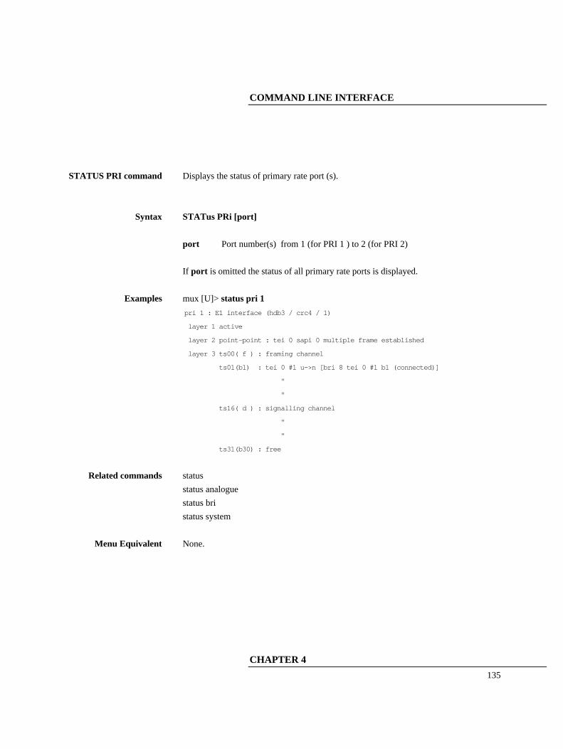
COMMAND LINE INTERFACE
CHAPTER 4
135
STATUS PRI command Displays the status of primary rate port (s).
Syntax STATus PRi [port] port Port number(s) from 1 (for PRI 1 ) to 2 (for PRI 2) If port is omitted the status of all primary rate ports is displayed.
Examples mux [U]> status pri 1 pri 1 : E1 interface (hdb3 / crc4 / 1)
layer 1 active
layer 2 point-point : tei 0 sapi 0 multiple frame established
layer 3 ts00( f ) : framing channel
ts01(b1) : tei 0 #1 u->n [bri 8 tei 0 #1 b1 (connected)]
"
"
ts16( d ) : signalling channel
"
"
ts31(b30) : free
Related commands status status analogue status bri status system
Menu Equivalent None.

COMMAND LINE INTERFACE
136
STATUS SYSTEM command
Displays system status.
Syntax STATus SYstem
Examples mux [U]> status system system:
hardware: dig19 (16U 2P [set to E1])
tone module: EPROM
modem module: not fitted
software: (development version) (flash)[ boot sector: v2.0b ]
tcp/ip : fixed
ip address : 192.168.0.130
subnet mask : 255.255.255.0
gateway : 0.0.0.0
snmp trap address 1 : 0.0.0.0
snmp trap address 2 : 0.0.0.0
snmp trap address 3 : 0.0.0.0
protocol: ETSI
real time clock: detected
access: user - read only
name: (no name)
password: (no password)
time: 23/12/98 12:11:04
comms: 115200,8,N,2 (ansi terminal)
calls: 0 active (0 on hold), 0 suspended (0 cleared)
Related commands status status analogue status bri status pri
Menu Equivalent None.

COMMAND LINE INTERFACE
CHAPTER 4
137
SUPER command Selects supervisor mode (read and write access).
The user is prompted for a password if there is a password stored.
Syntax SUPervisor
Examples mux [U]>supervisor OK mux [S]>
Related commands user set password
Menu Equivalent System Setup - System Mode

COMMAND LINE INTERFACE
138
SWL command
(Software Load) Uploads new software to FLASH. More details are given in an appendix.
Syntax SWL
Examples mux [S]>swl
Related commands None
Menu Equivalent System Setup - Reprogram FLASH

COMMAND LINE INTERFACE
CHAPTER 4
139
SWL ANALOGUE
command
Uploads new software to the analogue card. More details are given in an appendix.
Syntax SWL Analogue
Examples mux [S]>swl analogue
Related commands None
Menu Equivalent System Setup - Reprogram Analogue
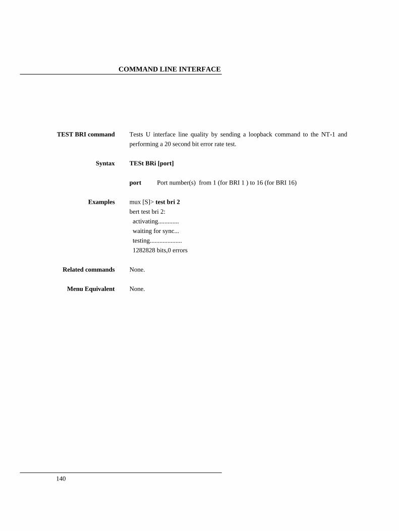
COMMAND LINE INTERFACE
140
TEST BRI command Tests U interface line quality by sending a loopback command to the NT-1 and performing a 20 second bit error rate test.
Syntax TESt BRi [port] port Port number(s) from 1 (for BRI 1 ) to 16 (for BRI 16)
Examples mux [S]> test bri 2 bert test bri 2: activating............. waiting for sync... testing.................... 1282828 bits,0 errors
Related commands None.
Menu Equivalent None.
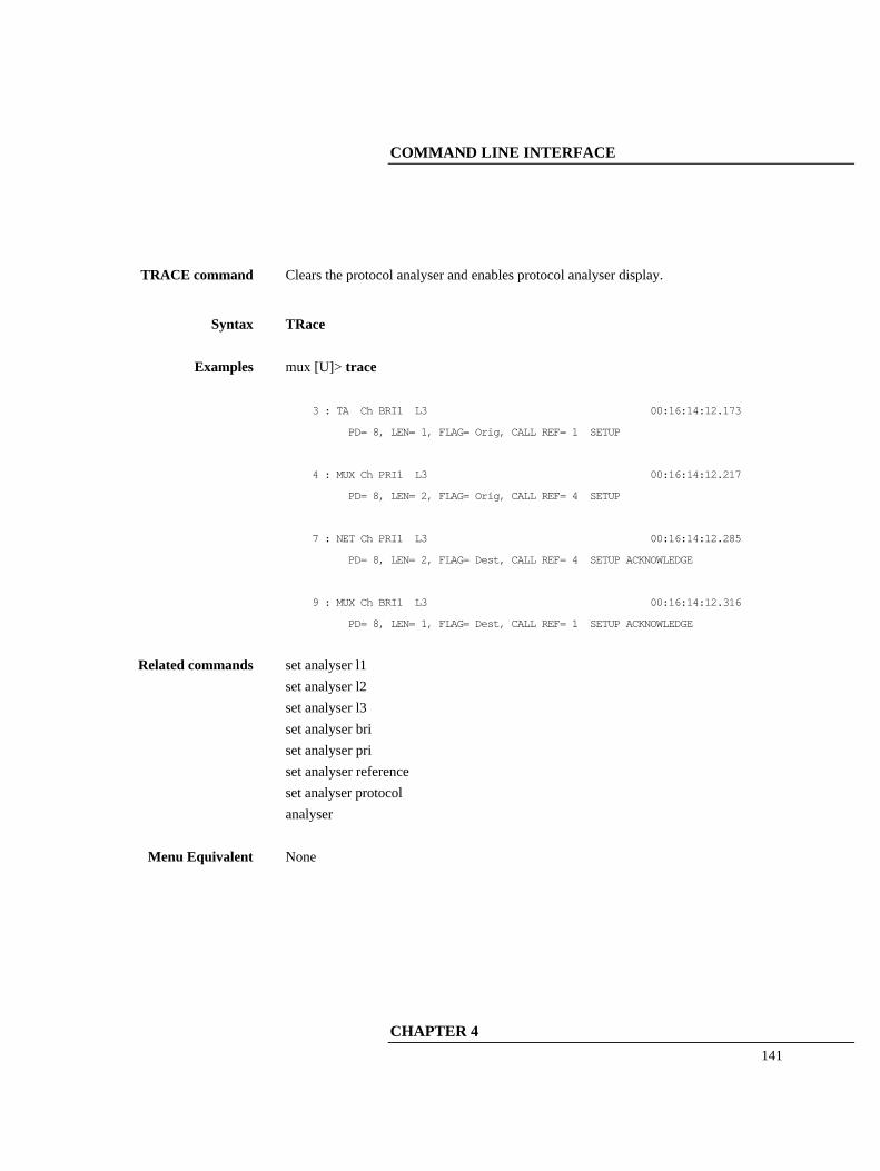
COMMAND LINE INTERFACE
CHAPTER 4
141
TRACE command Clears the protocol analyser and enables protocol analyser display.
Syntax TRace
Examples mux [U]> trace 3 : TA Ch BRI1 L3 00:16:14:12.173
PD= 8, LEN= 1, FLAG= Orig, CALL REF= 1 SETUP
4 : MUX Ch PRI1 L3 00:16:14:12.217
PD= 8, LEN= 2, FLAG= Orig, CALL REF= 4 SETUP
7 : NET Ch PRI1 L3 00:16:14:12.285
PD= 8, LEN= 2, FLAG= Dest, CALL REF= 4 SETUP ACKNOWLEDGE
9 : MUX Ch BRI1 L3 00:16:14:12.316
PD= 8, LEN= 1, FLAG= Dest, CALL REF= 1 SETUP ACKNOWLEDGE
Related commands set analyser l1 set analyser l2 set analyser l3 set analyser bri set analyser pri set analyser reference set analyser protocol analyser
Menu Equivalent None

COMMAND LINE INTERFACE
142
UPLOAD command Lists all the commands that would create the current configuration. If the output is logged to a file a command file is created which can be sent to arcaplex|Horizon later to restore this configuration. Some commands are preceded by a rem to prevent them being executed if a file generated in this way is used for configuration. NB When using a PC to send a command file make sure that it is set for hardware flow control.
Syntax UPload
Examples mux [S]> upload set analyser bri 1 off
set analyser bri 2 off
"
"
set terminal ansi
rem set time 12:15:42
Related commands None
Menu Equivalent None

COMMAND LINE INTERFACE
CHAPTER 4
143
USER command Selects user mode (read only).
Syntax USEr
Examples mux [S]>super OK mux [U]>
Related commands supervisor set password
Menu Equivalent System Setup - System Mode

COMMAND LINE INTERFACE
144
VERSION command Returns the current version number.
Syntax VErsion
Examples mux [U]> version software: V1.3a 23 December 1998 (flash)[ boot sector: v1.0a ]
Related commands None
Menu Equivalent Version information is displayed on copyright screen.

COMMAND LINE INTERFACE
CHAPTER 4
145
FAULT FINDING
146
Introduction This section seeks to provide some guidance on solving common problems encountered in using arcaplex|Horizon.
Changing a parameter on arcaplex|Horizon caused it to stop
operating.
Changing parameters on arcaplex|Horizon may cause the unit to change operating modes and appear to stop functioning. To recover from this condition reload the factory defaults (see Quick Reference Guide).
Windows terminal or telnet program will not move up and down menus.
When using the Windows terminal emulation program in its default configuration the <up> and <down> arrow keys will not function with the menus. This is because Windows uses these keys and does not pass any characters to arcaplex|Horizon. In most cases <up> can be replaced with the ‘u’ or ‘U’ key and <down> by the ‘d’ or ‘D’ key. Alternatively change the operation of the terminal program by disabling the “Use Function, Arrow and Ctrl Keys for Windows” option. Set the terminal program to ANSI or VT100 to work with default (ANSI) terminal setting. You may also have to select an option like “VT100 arrows”.
No communication with terminal port.
Communication failure can occur for several reasons. Firstly check that arcaplex|Horizon is powering up properly. The power LED should illuminate and the other LED's should turn on and off. The internal relays should usually switch on power up and this should be audible. Next check the cable. arcaplex|Horizon provides a DCE connection so a cable with a 9 way D male to 9 way D female connected pin for pin will connect arcaplex|Horizon to a PC.
FAULT FINDING
CHAPTER 5
147
If the cable is correct then check the communication parameters. The default is 19200 baud, no parity, 2 stop bits and 8 data bits. To restore the default communication parameters reload the factory defaults (see Quick Reference Guide).
Changing parameters had no effect on operation of arcaplex|Horizon.
Some parameters once changed will not effect the operation of the unit immediately. If arcaplex|Horizon does not seem to be operating properly use the <esc> key to go back to the previous menu. If this does not work then switch arcaplex|Horizon off and on again. Please inform arca technologies.
Protocol Analyser will not run.
Check the analyser option i.e. at least one level of decode must be enabled and the interface to which the terminal is connected must be enabled. If you are not sure set decode for layers 1, 2 and 3 on all interface ports.
Network connection will not activate at layer 1 (i.e. P led does not illuminate)
Check that you have selected the correct primary rate mode for the PRI line. Check PRI E1/T1 mode in Hardware Setup matches the PRI line. E1 - Check PRI E1 Mode in Hardware Setup matches the line coding and framing standard on the PRI line. If this information is not known try HDB3/CRC-4/Si=1. T1 - Check the network is compatible with arcaplex|Horizon. It should be T1 (1.544 Mbit/s) with Extended Super Frame (ESF) and B8ZS line coding.
Terminal will not activate at layer 1 (i.e. P led does not illuminate)
If the P LED does not illuminate then the physical connection between the terminal, and arcaplex|Horizon is not functioning. Check first that the terminal is connected to the correct interface type. The Copyright Screen displays the type of interface installed for each port.

FAULT FINDING
148
If it is a BRI terminal try changing the power settings in Hardware Setup. Set BRI S/U Power Feed to ON. If it is an S interface BRI terminal try setting BRI S Power Mode to both normal and restricted. For US originating products with U interfaces then BRI U Power Mode should be set to Sealing. To power NT-1’s the U interface power should be set to Normal. Be careful when switching to U interface normal power as products intended to be connected to current limited U interface may be damaged by non current limited power (e.g. Motorola Bitsurfer). For primary rate check that PRI E1/T! Mode in Hardware Setup matches the terminal. For E1 equipment check that PRI E1 Mode in Hardware Setup matches the line coding and framing standard for the terminal. If this information is not known try HDB3/CRC-4/Si=1. For T1 equipment check it is compatible with arcaplex|Horizon. arcaplex|Horizon supports Extended Super Frame (ESF) and B8ZS line coding.
Terminal will not make or answer a call. If the P light stays off see the section on "Terminal will not activate at layer 1". If the P light flashes check that there are not too many terminals on the line. For basic rate the maximum is 8 (1 for point-to-point) and for primary rate the maximum is 1. For a basic rate port check that the BRI Setup is correct in Software Setup. This should be point to point if it is a point-to-point terminal expecting TEI=0. Otherwise it should be point to multipoint which allows automatic TEI assignment. If the P light fails to light the terminal may be faulty. Now check that there are channels enabled on that port and that there are sufficient channels enabled on PRI 1 ie check Channel
FAULT FINDING
CHAPTER 5
149
Setup is correct in Software Setup. If ETSI protocol is set and routing mode is set to channel check that a route to PRI 1 has been set up. Check that the terminal is compatible with the network. For example if using an ETSI network the terminals should be ETSI compliant. Other terminals may not function due to protocol errors. For BRI TA's being used with National ISDN protocol check that the correct SPID has been entered in the TA. This should consist of the number for the TA (in Number Setup) + 0101. NB if BRI Require SPID in Software Setup is set to No arcaplex|Horizon will allow calls to made without a correct SPID but the TA may block the call itself. Use the protocol analyser to display the layer 3 messages. The called terminal may send DISCONNECT, RELEASE or RELEASE COMPLETE with a cause value indicating the problem. A potential problem may be that called terminal and calling terminal do not support the same bearer capability in which case the called terminal will send RELEASE COMPLETE with a cause “Incompatible Destination”. Another possibility is that the called terminal is expecting a Called Party Number or Calling Party Number information element in the SETUP message. These are optional services from the network.
Incoming calls are rejected or not routed correctly
If the B light on the called port switches on but the P light stays off see the section on "Terminal will not activate at layer 1". For a basic rate port check that the BRI Setup is correct in Software Setup. This should be point to point if it is a point-to-

FAULT FINDING
150
point terminal expecting TEI=0. Otherwise it should be point to multipoint which uses the global TEI (127). Now check that there are channels enabled on that port and that there are sufficient channels enabled on PRI 1 ie check Channel Setup is correct in Software Setup If ETSI protocol is set and routing mode is set to channel check that a route to PRI 1 has been set up. Otherwise check that Called Party Number and Number Setup are compatible as follows... Use the protocol analyser to check that the network is providing a CalledParty Number in the SETUP message and that a match number in Number Setup matches it. For ETSI protoco1 a match requires the n digits of the match number for the port that the call is to be routed to match the last n digits of the Called Party Number. For National ISDN protocol a match requires the match number for the BRI TA that the call is to be routed to match the Called Party Number. The n digits of the shorter number are compared to the last n digits of the longer number. This allows a match when an area code is not included in one of the numbers.
B channel not freed (B light stays on) when call is on hold
If ETSI protocol is set and routing mode is set to channel the b channel should not be freed. Otherwise.... When calls are placed on hold the B channel on PRI 1 is kept reserved. The b channel on the BRI for a call on hold is only freed if there is a spare channel on PRI 1. When the b channel is freed it is possible for the BRI to have more than 2 b channels on PRI 1 allocated to it. Hence to ensure that all enabled BRI's still have access to 2 b channels on PRI 1 the b channel for the call on hold on the BRI is only freed if there is a spare channel on PRI 1 or it is the first call on hold with b channel reserve on. The number of spare channels is (no. of channels enabled on PRI 1)

FAULT FINDING
CHAPTER 5
151
- ( no. of analogue channels enabled ) - ( no. of BRI channels enabled ) - (no. of channels enabled on PRI 2)

APPENDICES
152
Reprogramming the FLASH
New software can be uploaded via the serial port, modem(optional) or the ethernet port. Telnet and FTP are used with the Ethernet port. If the software is corrupted then upload has to be done via the serial port.
Initiating software upload From boot ROM
If the FLASH checksum is invalid arcaplex|Horizon will request reprogramming on power up. If the FLASH is corrupted but still passes checksum arcaplex|Horizon can be forced to request reprogramming on power up. Set your terminal/PC to 19200 baud, 8 data bits, no parity and 2 stop bits. Switch arcaplex|Horizon on and press <ctrl-d> while the LED's are all on. The following is displayed ISDN Multiplexer BOOT 2.0b 26th October 1999
Ready to upload new firmware into FLASH.
Confirm Yes/No (Y/N)
NB if a debug prompt is displayed press <escape>. If you wish to change to a higher baud rate it is possible to change over to 115200 baud by pressing <Escape> <9> <Return> .Set your PC/terminal to match and press <Escape>. The prompt will be re-displayed. Press <Y> to proceed.
Initiating software upload from the menu system
or command line interface
First of all you may wish to change to a higher baud rate in hardware setup or by using set communication and set your PC/terminal to match. Select Reprogram FLASH in system setup and press <Enter> or type swl <ENTER> from the command line interface. NB supervisor mode is required.

APPENDICES
153
The following is displayed if the serial port is being used. Press <1> to proceed using serial port or <2> to proceed using FTP. Ready to upload new firmware into FLASH
Select download method
(1)- serial port (2) - FTP (ESC) – abort
The following is displayed if the ethernet port is being used (Telnet access). Press <Y> to proceed using FTP. Ready to upload new firmware into FLASH (via FTP)
Confirm Yes/No (Y/N)
The following is displayed if the modem is being used Press <Y> to proceed. Ready to upload new firmware into FLASH
Confirm Yes/No (Y/N)
File transfer using serial port If upload was initiated from the menu or command line the ISDN
protocol stack is stopped and the line cards are reset (all LED’s on the line cards will come on, relays may click on S cards). The following is displayed ISDN Multiplexer BOOT 2.0b 26th October 1999
Clearing RAM
Ready for S-RECORDs
Now send the file as raw ASCII. (or press <ESCAPE> to abort) The LED's for PRI 1 will scroll during the download. If the file is valid the following is displayed S-RECORD download complete
initialise FLASH programming
FLASH erase
LED’s will scroll for a few seconds then the following is
APPENDICES
154
displayed FLASH program
LED’s will scroll for a few more seconds then the following is displayed FLASH program complete
If the file is not valid an error message will be displayed. The existing FLASH program will not have been changed. If upload was initiated using the boot ROM then the following is displayed Running debugger
Boot Debugger
>00C00164
Type <z> <Enter> to restart arcaplex|Horizon. If upload was initiated using the command line or menu then arcaplex|Horizon will restart automatically if there were no errors otherwise press a key to make arcaplex|Horizon restart.

APPENDICES
155
File transfer using FTP The ISDN protocol stack is stopped. The following is displayed Ready for s-records
send via FTP to 192.168.0.40
with user name 'arca', password 'technologies'
Now using an FTP program log in and send the file. LED’s on PRI 1 will scroll during the upload. If the file is valid the following is displayed valid s-record file received
DO NOT SWITCH OFF
- system will reset when erase/program sequence is complete
If the upload was initiated using Telnet then the following is displayed. telnet will disconnect - reconnection possible in 30 seconds
The line cards are reset (all LED’s on the line cards will come on, relays may click on S cards). LED’s on PRI 1 will scroll during the erase/program sequence. arcaplex|Horizon will then reset. If the file is not valid an error message will be displayed. The existing FLASH program will not have been changed. arcaplex|Horizon will reset automatically. Log out or disconnect using the FTP program.
File transfer using modem The ISDN protocol stack is stopped. The following is displayed Ready for s-records
Now send the file as raw ASCII. (or press <ESCAPE> to abort) LED’s on PRI 1 will scroll during the upload. If the file is valid the following is displayed

APPENDICES
156
valid s-record file received
DO NOT SWITCH OFF
- system will reset when erase/program sequence is complete
modem will disconnect - reconnection possible in 30 seconds
The line cards are reset (all LED’s on the line cards will come on, relays may click on S cards). LED’s on PRI 1 will scroll during the erase/program sequence. arcaplex|Horizon will then reset. If the file is not valid an error message will be displayed. The existing FLASH program will not have been changed. arcaplex|Horizon will reset automatically.

APPENDICES
157

APPENDICES
158
Reprogramming an Analogue card
New software for the analogue card can be uploaded via the serial port, modem(optional) or the ethernet port. Telnet and FTP are used with the Ethernet port. There are 2 pieces of software which can be loaded on to an analogue card
1 – card software 2 – DSP module software
Initiating software upload
to analogue card First of all you may wish to change to a higher baud rate in hardware setup or by using set communication and set your PC/terminal to match. Select Reprogram Analogue in system setup and press <Enter> or type swl analogue <ENTER> from the command line interface. NB supervisor mode is required. The following is displayed if the serial port is being used. Press <1> to proceed using serial port or <2> to proceed using FTP. Ready to upload new firmware into analogue card
Select download method
(1)- serial port (2) - FTP (ESC) – abort
The following is displayed if the ethernet port is being used (Telnet access). Ready to upload new firmware into analogue card (via FTP)
The following is displayed if the modem is being used Ready to upload new firmware into analogue card

APPENDICES
159
The following is displayed. Press <1> or <2> to select the line card to be reprogrammed. Select line card
(1) – Card 1 (2) – Card 2 (ESC) - abort
The following is displayed. Press <1> to reprogram the card software or <2> to reprogram the DSP module software. Select card or DSP module
(1) - card (2) – DSP
Reprogramming card software If the software is to be uploaded via FTP the following is displayed [card %d, current version %s]
Requesting analogue card to accept new program
Ready for s-records
send via FTP to 192.168.0.40
with user name 'arca', password 'technologies'
Now using an FTP program log in and send the file or press <escape> to abort. Otherwise the following is displayed [card %d, current version %s]
Requesting analogue card to accept new program
Ready for s-records
Now send the file as raw ASCII or press <escape> to abort. In both cases LED’s on PRI 1 will scroll during the upload. When upload is complete the following is displayed Transferring s-records
The LED’s continue to scroll as the file is transferred to the analogue card. When upload is successfully completed the following is displayed Download result: 'OK'
Waiting for analogue card to reprogram FLASH
- DO NOT SWITCH OFF

APPENDICES
160
[Programming takes around 30 seconds]
The LED’s continue to scroll as the analogue card reprograms its FLASH with the new software. The following should be displayed Program result: 'OK'
If telnet is being used the following is displayed telnet will disconnect - reconnection possible in 30 seconds
If the modem is being used the following is displayed modem will disconnect - reconnection possible in 30 seconds
The line cards are reset (all LED’s on the line cards will come on, relays may click on S cards). arcaplex|Horizon will now reset. If the file is not valid an error message will be displayed. The existing card software will not have been changed. arcaplex|Horizon will reset automatically. If FTP is being used log out or disconnect using the FTP program.

APPENDICES
161
Reprogramming DSP module software If the software is to be uploaded via FTP the following is displayed [card %d, DSP version %s]
Ready for s-records
send via FTP to 192.168.0.40
with user name 'arca', password 'technologies'
Now using an FTP program log in and send the file or press <escape> to abort. Otherwise the following is displayed [card %d, DSP version %s]
Ready for s-records
Now send the file as raw ASCII or press <escape> to abort. In both cases LED’s on PRI 1 will scroll during the upload. When upload is complete the following is displayed Requesting analogue card to accept new DSP program
Transferring s-records
The LED’s continue to scroll as the file is transferred through the analogue card to the DSP module. When upload is successfully completed the following is displayed Program result: 'OK'
Waiting for analogue card to reprogram DSP
- DO NOT SWITCH OFF
[Programming takes around 30 seconds]
The LED’s continue to scroll as the analogue card reprograms the DSP module with the new software. The following should be displayed Program result: 'OK'
If telnet is being used the following is displayed telnet will disconnect - reconnection possible in 30 seconds
If the modem is being used the following is displayed modem will disconnect - reconnection possible in 30 seconds

APPENDICES
162
The line cards are reset (all LED’s on the line cards will come on, relays may click on S cards). arcaplex|Horizon will now reset. If the file is not valid an error message will be displayed. The existing DSP module software will not have been changed. arcaplex|Horizon will reset automatically. If FTP is being used log out or disconnect using the FTP program.

APPENDICES
163
Default Settings This table shows the default settings for arcaplex|Horizon. Some settings
apply to only one protocol.
ETSI mode only settings
The following settings apply only to ETSI mode Routing Mode Routing Setup Use Internal Tones In National ISDN mode routing is always number based and internal tones are always used.
National ISDN mode only settings
The following settings apply only to National ISDN mode BRI Require SPID BRI HOLD reserve channel Numbering plan In ETSI mode channel reserve on hold is always enabled. The other settings are not relevant.
Numbers Separate numbers are stored for ETSI and National ISDN protocols. Hence 2 sets of default numbers are listed.
SPID’s The SPID's (National ISDN protocol only) are fixed as the number in Number Setup with 0101 appended. e.g. BRI 12 has SPID's 3841120101 and 3841520101 if the default numbers are unchanged.
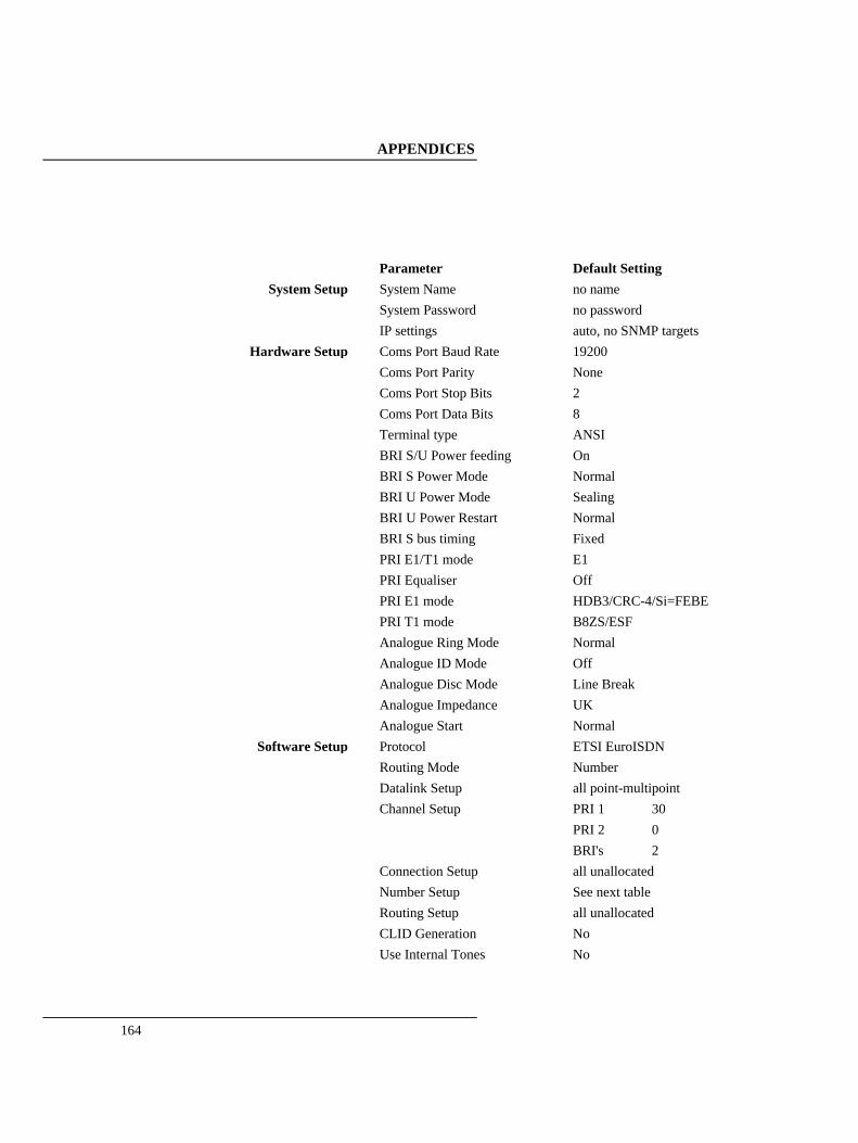
APPENDICES
164
Parameter Default Setting
System Setup System Name System Password IP settings
no name no password auto, no SNMP targets
Hardware Setup Coms Port Baud Rate Coms Port Parity Coms Port Stop Bits Coms Port Data Bits Terminal type BRI S/U Power feeding BRI S Power Mode BRI U Power Mode BRI U Power Restart BRI S bus timing PRI E1/T1 mode PRI Equaliser PRI E1 mode PRI T1 mode Analogue Ring Mode Analogue ID Mode Analogue Disc Mode Analogue Impedance Analogue Start
19200 None 2 8 ANSI On Normal Sealing Normal Fixed E1 Off HDB3/CRC-4/Si=FEBE B8ZS/ESF Normal Off Line Break UK Normal
Software Setup Protocol Routing Mode Datalink Setup Channel Setup Connection Setup Number Setup Routing Setup CLID Generation Use Internal Tones
ETSI EuroISDN Number all point-multipoint PRI 1 30 PRI 2 0 BRI's 2 all unallocated See next table all unallocated No No

APPENDICES
165
Analyser Setup
Layer 1 Hardware Layer 2 Data Link Layer 3 Call Control Channel filter Call reference filter Analyser Specification
Inactive Inactive ASCII long display all disabled Inactive ETSI

APPENDICES
166
Number Setup for ETSI mode BRI 1 or A1, A2
BRI 2 or A3, A4 BRI 3 or A5, A6 BRI 4 or A7, A8 BRI 5 or A9, A10 BRI 6 or A11, A12 BRI 7 or A13, A14 BRI 8 or A15, A16 BRI 9 or A17, A18 BRI 10 or A19, A20 BRI 11 or A21, A22 BRI 12 or A23, A24 BRI 13 or A25, A26 BRI 14 or A27, A28 BRI 15 or A29, A30 BRI 16 or A31, A32 PRI 2
01, 51 02, 52 03, 53 04, 54 05, 55 06, 56 07, 57 08, 58 09, 59 10, 60 11, 61 12, 62 13, 63 14, 64 15, 65 16, 66 99
Number Setup for National ISDN mode BRI 1 or A1, A2 BRI 2 or A3, A4 BRI 3 or A5, A6 BRI 4 or A7, A8 BRI 5 or A9, A10 BRI 6 or A11, A12 BRI 7 or A13, A14 BRI 8 or A15, A16 BRI 9 or A17, A18 BRI 10 or A19, A20 BRI 11 or A21, A22 BRI 12 or A23, A24 BRI 13 or A25, A26 BRI 14 or A27, A28 BRI 15 or A29, A30 BRI 16 or A31, A32 PRI 2
384101, 384151 384102, 384152 384103, 384153 384104, 384154 384105, 384155 384106, 384156 384107, 384157 384108, 384158 384109, 384159 384110, 384160 384111, 384161 384112, 384162 384113, 384163 384114, 384164 384115, 384165 384116, 384166 384199

APPENDICES
167
ISDN interface Pin-outs The following table shows the pin-outs of the RJ45 connectors for the ISDN interfaces.
PRI 1 PRI 2 BRI
E1 or T1 E1 or T1 S U
1 R- T- NC NC
2 R+ T+ NC NC
3 NC NC R- NC
4 T- R- T- RING
5 T+ R+ T+ TIP
6 NC NC R+ NC
7 NC NC NC NC
8 NC NC NC NC
Analogue Pin-out The following table shows the pin-out of the RJ11 connector for
the analogue (PSTN) interfaces.
RJ11 connector
1 NC
2 NC
3 TIP
4 RING
5 NC
6 NC
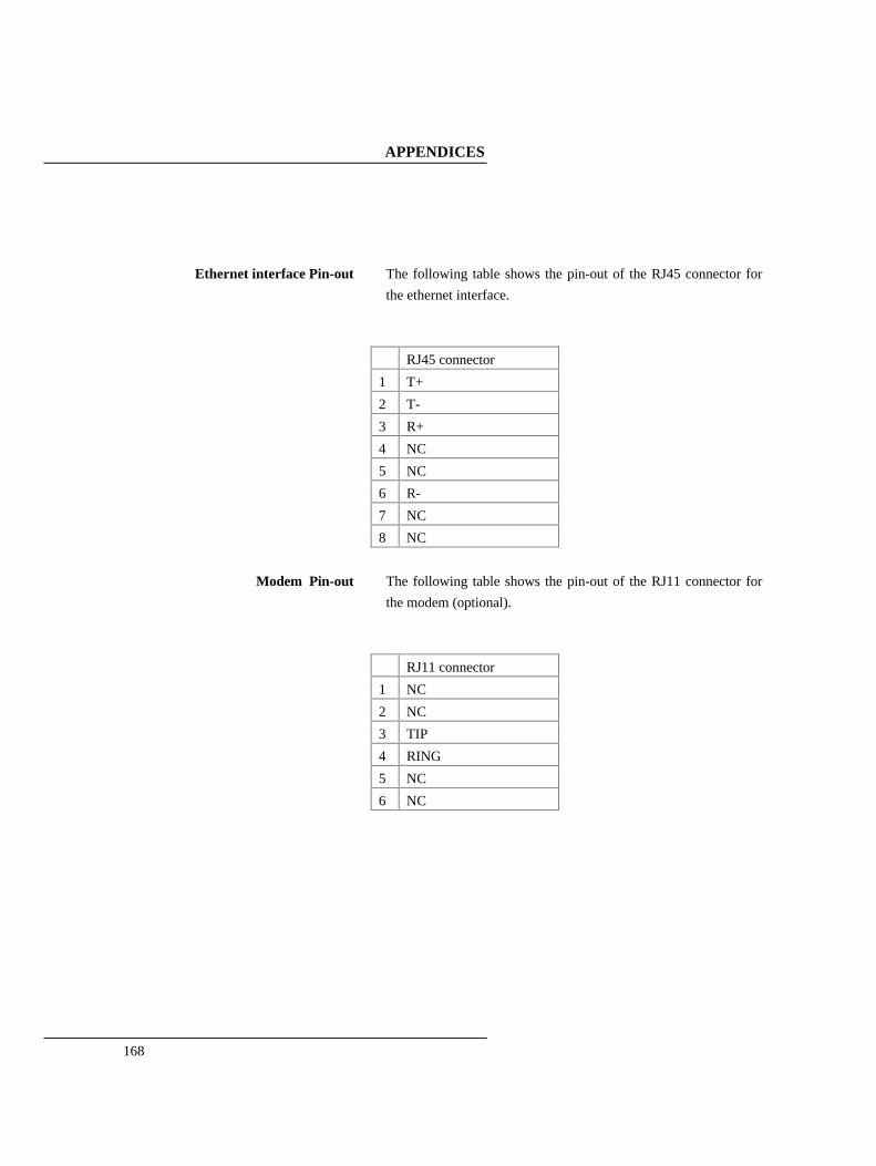
APPENDICES
168
Ethernet interface Pin-out The following table shows the pin-out of the RJ45 connector for
the ethernet interface.
RJ45 connector
1 T+
2 T-
3 R+
4 NC
5 NC
6 R-
7 NC
8 NC
Modem Pin-out The following table shows the pin-out of the RJ11 connector for
the modem (optional).
RJ11 connector
1 NC
2 NC
3 TIP
4 RING
5 NC
6 NC
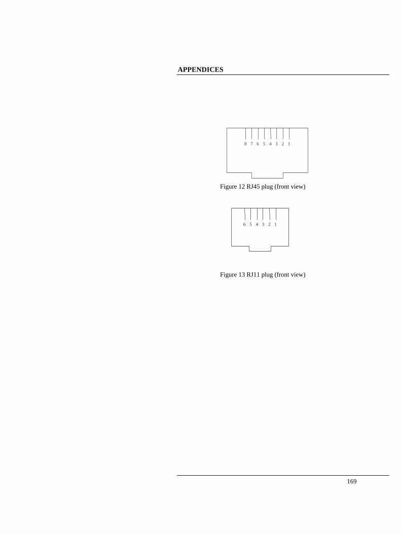
APPENDICES
169
8 7 6 5 4 3 2 1
Figure 12 RJ45 plug (front view)
6 5 4 3 2 1
Figure 13 RJ11 plug (front view)
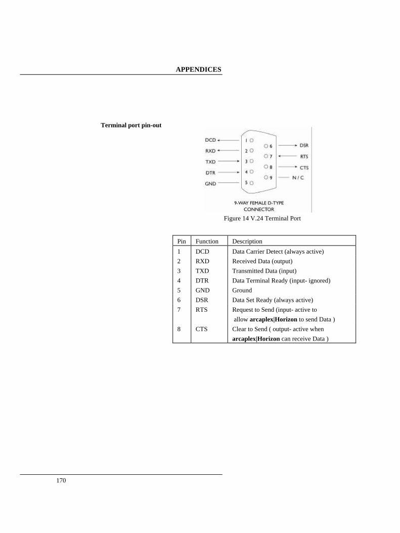
APPENDICES
170
Terminal port pin-out
Figure 14 V.24 Terminal Port
Pin Function Description
1 DCD Data Carrier Detect (always active) 2 RXD Received Data (output) 3 TXD Transmitted Data (input) 4 DTR Data Terminal Ready (input- ignored) 5 GND Ground 6 DSR Data Set Ready (always active) 7 RTS Request to Send (input- active to
allow arcaplex|Horizon to send Data ) 8 CTS Clear to Send ( output- active when
arcaplex|Horizon can receive Data )

APPENDICES
171
BRI Power Feeding Figure 15 shows a schematic of how the power is supplied at the
ISDN S0 interface port while figure 16 shows a schematic of U interface power feeding.
Figure 15 Schematic of 40 V Power Supply (S interface)
Figure 16 Schematic of 88V Power Supply (U interface)

APPENDICES
172
APPENDICES
173
Examples of Number Setup
(ETSI protocol) This appendix gives some example settings for Number Setup when ETSI protocol is selected and describes how incoming calls are routed (if Routing Mode is set to Number) and how the calling party number/subaddress on outgoing calls is effected (if CLID generation is on) in each case. The examples for the telephone numbers are given as 7 digits ie just the local number. Telephone numbers with area code e.g. 04445551234 could be used but if the network doesn't include the area code in the Called Party Number then incoming calls would not be routed correctly. Shorter numbers could also be used. e.g. if all the numbers on the PRI are the same apart from the last 2 digits then a 2 digit number (like the default numbers) would be sufficient to route correctly. When setting up the numbers it is important to delete any existing numbers that are no longer required. For simplicity the following text assumes that the same format of numbers is used for each interface.
Reject all incoming calls Delete all numbers in Number Setup. Set PRI 2 to have 0 channels in Channel Setup CLID generation (for outgoing calls) is not appropriate in this case.
Route all incoming calls to PRI 2
Delete all numbers in Number Setup. Set PRI 2 to have some channels in Channel Setup CLID generation (for outgoing calls) is not appropriate in this case. Calls will be routed to PRI 2 if there is a free b channel.
Route to first interface with a free Store * or ? for first number for each interface that is to receive

APPENDICES
174
channel incoming calls. CLID generation (for outgoing calls) is not appropriate in this case. Incoming calls with any Called Party Number will be accepted by the first port with a free b channel (any Called Party Subaddress is ignored).
Route by telephone number Store telephone number(s) (e.g. 5551234) for each interface that is to receive incoming calls. If CLID generation is on use the first number for an interface to hold the telephone number to be used when a Calling Party Number is to be changed on or added to an outgoing call. 10 different telephone numbers can be assigned to the same interface. The same number can be used for several interfaces to form a multi-line hunt group. For the example of 5551234
Incoming calls with Called Party Number ending 5551234 will be accepted if there is a free b channel (any Called Party Subaddress is ignored). Outgoing calls (with CLID generation on) will have their Calling Party Number checked (any Calling Party Subaddress is ignored). Outgoing calls with Calling Party Number of 5551234 will have their Calling Party Number unchanged. Otherwise if none of the numbers for that port match then the Calling Party Number (and Subaddress) will be changed to the first number (and Subaddress) stored for that port.

APPENDICES
175
Route by subaddress
Store '?#' followed by a subaddress (e.g. ?#23) for each interface that is to receive incoming calls. NB 10 different subaddresses can be assigned to the same interface. CLID generation (for outgoing calls) is not appropriate with this format. For the example of ?#23
Incoming calls with any Called Party Number and with a subaddress of 23 will be accepted if there is a free b channel.
Route by telephone number and
subaddress
Store a telephone number followed by '#' followed by a subaddress (e.g. 5551234#44) for each interface that is to receive incoming calls. NB 10 different telephone numbers and subaddresses can be assigned to the same interface. If CLID generation is on use the first number for an interface to hold the telephone number and subaddress to be used when Calling Party Number and Calling Party Subaddress are to be changed on or added to an outgoing call. For the example of 5551234#44
Incoming calls with Called Party Number ending 5551234 and with a subaddress of 44 will be accepted. Outgoing calls (with CLID generation on) will have their Calling Party Number and Calling Party Subaddress checked. Outgoing calls with Calling Party Number of 5551234 and Calling Party Subaddress of 44 will have their Calling Party Number and Calling Party Subaddress unchanged. Otherwise if none of the numbers for that port match then the Calling Party Number (and Subaddress) will be changed to the first number (and Subaddress) stored for that port.

APPENDICES
176
Route based on telephone number with last digit as wildcard
Store a telephone number with a '?' in place of the last digit (e.g. 555123?) for each interface that is to receive incoming calls. Store it as the first number if CLID generation is on and it is the preferred choice for when a Calling Party Number is to be changed on or added to an outgoing call. NB the '?' is changed to 0 if it is used as the Calling Party Number. This is a useful way of allocating 10 numbers (for MSN) to a basic rate interface. For the example of 555123?
Incoming calls with Called Party Number ending 5551230 to 5551239 will be acceptedif there is a free b channel (any Called Party Subaddress is ignored) . Outgoing calls (with CLID generation on) will have their Calling Party Number checked (any Calling Party Subaddress is ignored). Outgoing calls with Calling Party Number of 5551230 to 5551239 will have their Calling Party Number unchanged. Otherwise if none of the numbers for that port match then the Calling Party Number (and Subaddress) will be changed to the first number (and Subaddress) stored for that port.

APPENDICES
177
Route based on telephone number allowing for extension number
(* option)
Store a telephone number with a '*' after the last digit (e.g. 5551234*) for each interface that is to receive incoming calls. Store it as the first number if CLID generation is on and it is the preferred choice for when a Calling Party Number is to be changed on or added to an outgoing call. For the example of 5551234*
Incoming calls with Called Party Number containing 5551234 will be accepted (any Called Party Subaddress is ignored). Outgoing calls (with CLID generation on) will have their Calling Party Number checked (any Calling Party Subaddress is ignored). Outgoing calls with Calling Party Number starting with 5551234 will have their Calling Party Number unchanged. Otherwise if none of the numbers for that port match then the Calling Party Number (and Subaddress) will be changed to the first number (and Subaddress) stored for that port. If the received Calling Party Number is 5 digits or less it is assumed to be an extension number and will be appended to the new Calling Party Number.
Route based on telephone number
allowing for extension number (+ option)
Store a telephone number with a '+' after the last digit (e.g. 5551234+) for each interface that is to receive incoming calls. Store it as the first number if CLID generation is on and it is the preferred choice for when a Calling Party Number is to be changed on or added to an outgoing call. For the example of 5551234+
Incoming calls with Called Party Number containing 5551234 will be accepted (any Called Party Subaddress is ignored). The 5551234 and any preceding digits will not be passed through to the called interface. This is so that only the extension number is passed through.

APPENDICES
178
Outgoing calls (with CLID generation on) will have their Calling Party Number checked (any Calling Party Subaddress is ignored). Outgoing calls with Calling Party Number starting with 5551234 will have their Calling Party Number unchanged. Otherwise if none of the numbers for that port match then the Calling Party Number (and Subaddress) will be changed to the first number (and Subaddress) stored for that port. If the received Calling Party Number is 5 digits or less it is assumed to be an extension number and will be appended to the new Calling Party Number.
APPENDICES
179
Examples of Number Setup
(National ISDN protocol) This appendix gives some example settings for Number Setup when National ISDN protocol is selected and describes how incoming calls are routed and (if CLID generation is on) how the calling party number on outgoing calls is effected in each case. The examples for the telephone numbers are given as 7 digits ie just the local number. Telephone numbers with area code e.g. 4445551234 could also be used. When setting up the numbers it is important to delete any existing numbers that are no longer required. For simplicity the following text assumes that the same format of numbers is used for each interface. Subaddressing is not supported when National ISDN protocol is selected.
Reject all incoming calls Delete all numbers in Number Setup. Set PRI 2 to have 0 channels in Channel Setup CLID generation (for outgoing calls) is not appropriate in this case. Program the SPID's of BRI equipment as 0101 if the BRI equipment needs a SPID to make outgoing calls.
Route all incoming calls to PRI 2
Delete all numbers in Number Setup. Set PRI 2 to have some channels in Channel Setup CLID generation (for outgoing calls) is not appropriate in this case. Program the SPID's of BRI equipment as 0101 if the BRI equipment needs a SPID to make outgoing calls.

APPENDICES
180
Calls will be routed to PRI 2 if there is a free b channel.
Route by telephone number Store 1 or 2 telephone number(s) (e.g. 5551234) for each basic rate interface that is to receive incoming calls. Program the SPID's of BRI equipment as telephone number+0101 if the BRI equipment needs a SPID to make outgoing calls or accept incoming calls. This also allows calls to be routed to a specific TA. For the example of 5551234
Incoming calls with Called Party Number ending 5551234 will be accepted if there is a free b channel. Outgoing calls (with CLID generation on) will have their Calling Party Number checked. Outgoing calls with Calling Party Number ending 5551234 will have their Calling Party Number unchanged. If the endpoint identifier (linked to the SPID) is not included then Calling Party Number will be unchanged if it matches the other number for that interface. Otherwise the Calling Party Number will be changed. The new Calling Party Number will be the number associated with the endpoint identifier (linked to the SPID) if the endpoint identifier is included. If the endpoint identifier is not included then the first number for that interface will be used. When used for a basic rate interface the SPID associated with the telephone number 5551234 is 55512340101.
APPENDICES
181
SNMP support
arcaplex|Horizon supports SNMP to allow remote monitoring. SNMP is used via the Ethernet port. It should be accessed using a PC running SNMP software. It is necessary to add the arca MIB file to the programs MIB Database and compile it to access the custom SNMP status and correctly display the custom trap. The MIB file is available from arca technologies.
Polling An SNMP program can be used to poll arcaplex|Horizon and display if it is not responding e.g. if power cut off.
Traps A “cold start” trap is generated when arcaplex|Horizon powers up or is reset. NB “warm start” trap is not supported. A custom trap is generated when a PRI port becomes inactive (at layer 1). Traps are sent to the targets defined in System Setup or by the set target command. They can be disabled by setting the targets to 0.0.0.0. The targets should be running an SNMP program to accept the traps and display them and/or notify a designated person. Traps will not be sent if arcaplex|Horizon is set to get an IP address automatically and no IP address has been received. The cold start trap may not be sent with automatic IP addressing.
Standard SNMP status arcaplex|Horizon supports the standard MIB 2 features such as system description. These items can be found in the “mgmt” group when using a MIB Browser.
Custom SNMP status arcaplex|Horizon supports status monitoring of the ISDN and analogue ports. The serial number can also be accessed. For basic rate ports the following can be monitored
- layer 1 (active / inactive)

APPENDICES
182
- layer 2 (TEI values and datalink status) - b channels (free / call / connection / disabled) - power feeding status (off / on / limiting) - power feeding mode (off / normal / restricted [S]/ sealing[U]) - interface type (S / U / not fitted)
For primary rate ports the following can be monitored
- layer 1 (active / inactive) - layer 2 (TEI values and datalink status) - b channels (free / call / connection / disabled)
For analogue ports the following can be monitored - channel (free / call / disabled) - fitted / not fitted
All these items can be found in the “arca” group (part of the “private” group) when using a MIB Browser.
GLOSSARY
183
AMI Alternate Mark Inversion B8ZS Binary 8 Zeros Suppression BOOTP Bootstrap Protocol BRI Basic Rate Interface CLID Calling Line Identification CRC-4 Cyclic Redundancy Check -4 DDI Direct Dialling In DHCP Dynamic Host Configuration Protocol ESF Extended Super Frame ETSI European Telecommunications Standards Institute FSK Frequency Shift Keying FTP File Transfer Protocol HDB3 High Density Bipolar 3 IP Internet Protocol ISDN Integrated Services Digital Network MIB Management Information Base MSN Multiple Subscriber Numbering PRI Primary Rate Interface PSTN Public Switched Telephone Network REN Ring Equivalent Number SNMP Simple Network Management Protocol SPID Service Profile Identifier TA Terminal Adapter TEI Terminal Equipment Identifier
S 4 wire point-to-multipoint BRI line (can also be used as point-to-point) U 2 wire point-to-point BRI line
E1 2.048 Mbit/s PRI line with up to 30 b channels as used in most countries T1 1.544 Mbit/s PRI line up to 23 b channels as used in the USA and some other countries