arc solutions design guide v5 - fileburstarcsolutions.fileburst.com/downloads/arc solutions design...
TRANSCRIPT

Arc Solutions
Design Guide
Version 5.0.x

2
© 2003 - 2008 Arc Solutions (International) Ltd. All rights reserved
No part of this documentation may be reproduced in any form or by any means or used to make any derivative work (such as translation, transformation, or adaptation) without permission from Arc Solutions (International) Limited.
Arc Solutions (International) Limited reserves the right to revise this documentation and to make changes to its content from time to time without obligation on the part of Arc Solutions (International) Limited to provide notification of such revision or change.
Cisco is a registered trademark of Cisco, inc.
Unless otherwise indicated, Arc Solutions (International) Limited registered trademarks are registered in the United Kingdom and may or may not be registered in other countries.
All trademarks acknowledged
Arc Solutions (International) Ltd. Innovation House Turnhams Green Park Pincents Lane, Tilehurst Reading, Berkshire RG31 4UH UK
A Mettoni Limited Company
t: +44(0) 870 220 2203 f: +44(0) 870 220 2208
e: [email protected] w: www.arcsolutions.com
1st Edition, September 2008
The equipment complies with all the relevant conditions if used in accordance with the manual.

3
Document History Reason of Modification Author/Reviewer Version Date
Original document Written Bennie Grant 1.0 15/03/2004
Document Upgraded Shafiq-us-salam 1.1 30/06/2004
Company Name change and minor changes Martin Taylor 1.2 01/03/05
Remote SQL Server Support added Bennie Grant 1.3 07/03/05
BLF Support Limitations Added and TCP Port Details added
Bennie Grant 1.4 06/09/05
XML Whisper/Page, PCP & Unity Integration details added
Bennie Grant 1.5 17/11/05
XML Status Management details added Bennie Grant 1.6 19/12/05
XML Whisper Page – Cisco 7920 Issue detailed
Bennie Grant 1.7 05/06/06
Witness Call Recording Information Added Bennie Grant 1.8 26/06/06
Further TCP/IP Port information added Bennie Grant 1.9 04/07/06
Additional “Remote SQL” for v4.1.3sr2 onwards
Bennie Grant 1.10 21/05/07
CTI Scalability Section added Bennie Grant 1.11 16/06/07
Sections 19-23 added to cater for releases 5.0.0 and 5.0.1
Martin Taylor 1.12 05/08/08

4
Section 1: Purpose and Audience This document is intended for the following audience: Those involved in the planning and implementation of an ARC Connect Solution. Those who are Arc Connect Administrators. Section 2: Copyright Statement Copying of this document by you or any third party is strictly prohibited. This document contains confidential information and cannot be disclosed without the permission of Arc Solutions Ltd.
Section 3: Usage of this document This document should be used in conjunction with the ARC Pre-Installation Guide to assist you in the successful planning and implementation of an ARC Connect system. This document assumes basic knowledge of the ARC Connect system. This document will discuss the possible implementation scenarios, taking into account various topologies and environmental issues.

5
Contents
Section 1: Purpose and Audience ................................................. 4 Section 2: Copyright Statement ................................................... 4 Section 3: Usage of this document............................................... 4 Section 4: ARC Connect Terminology ........................................... 7 Section 5: Overview of Arc Connect Architecture......................... 8
5.1 Call Flow ............................................................................................ 8 5.2 Call Flow Diagram ............................................................................. 9
Section 6: CallManager Compatibility ........................................ 10 6.1 Calling Search Spaces and Partitions .............................................. 10 6.2 “ARC Controlled CTI Devices” and CallManager configuration....... 11 6.3 CTIManager and Cisco TSP Configuration....................................... 13
Section 7: CallManager/CTI Manager Resilience ....................... 15 7.1 CTIManager service fails ................................................................. 15 7.2 CallManager fails............................................................................. 15
Section 8: ARC Server Resilience ............................................... 16 8.1 One ARC Server ............................................................................... 16 8.2 Two ARC Servers ............................................................................. 16
Section 9: Arc LDAP synchronization.......................................... 17 9.1 LDAP synchronization ..................................................................... 17 9.2 Data Preparation on LDAP Server ................................................... 18 9.3 Configuring Arc LDAP Synch ........................................................... 18
Section 10: Remote SQL Server support ...................................... 19 10.1 Configuration requirements ............................................................ 19 10.2 Additional Configuration required for Arc v4.1.3sr2 onwards ........ 19
Section 11: Operator Busy Lamp Field Limitations....................... 21 Section 12: XML Whisper/Page.................................................... 22
12.1 Handset Support.............................................................................. 22 12.2 Call Flow design .............................................................................. 22 12.3 Scalability ........................................................................................ 22
Section 13: Personal Call Park (PCP) ........................................... 23 13.1 “Recognised” number...................................................................... 23 13.2 “Unrecognised” number ................................................................. 23 13.3 Considerations................................................................................. 23
Section 14: XML Status Management........................................... 24 Section 15: Unity Voicemail Integration ...................................... 25
15.1 Integrating with the Arc Console Operator..................................... 25 15.2 How this works................................................................................ 26
Section 16: Witness Integration with Arc Connect ...................... 27 16.1 Arc Server Integration .................................................................... 27 16.2 On the Witness Server..................................................................... 27 16.3 Available information ...................................................................... 27
Section 17: AntiVirus support on an Arc Server ........................... 28 17.1 Exclusions........................................................................................ 28
Section 18: Supported Remote Access Applications .................... 29 Section 19: Calendar Integration ................................................. 30
19.1 Introduction .................................................................................... 30 19.2 Functional Details............................................................................ 30
19.1.1. System Integration details...........................................................30 Section 20: SMS integration ......................................................... 31
20.1 Protocols.......................................................................................... 32

6
20.2 Tenancy ........................................................................................... 32 20.3 Communities................................................................................ 32
Section 21: CUPS Integration....................................................... 33 21.1 Arc Architecture Overview ............................................................. 33
Section 22: Consolidated Presence .............................................. 36 22.1 Presence Integration....................................................................... 36
22.1.1. Presence Preferences..................................................................36 22.2 Licensing...................................................................................... 36
Section 23: Serial Calling.............................................................. 37 Section 24: Other Considerations................................................. 38
24.1 Codecs ............................................................................................. 38 24.2 Cisco CTI Scalability ........................................................................ 41 24.3 Bandwidth ....................................................................................... 42 24.4 Arc Connect Client Applications and Shared Lines.......................... 43 24.5 Arc Connect TCP Ports..................................................................... 43 24.6 Licensing ......................................................................................... 44 24.7 Further information......................................................................... 44
Section 25: Appendixes ................................................................ 45 Appendix 1: Sample Topologies.................................................................. 45 A1.1 Single Site Topology........................................................................ 45 A1.2 Single Site Resilient ARC Server Topology...................................... 46 A1.3 Centralised ARC Server with Local and Remote Clients.................. 47 A1.4 Multi – Cluster Scenario .................................................................. 48 Appendix 2: Calculations ............................................................................ 49 A2.1 Device Weightings........................................................................... 49 A2.2 ARC Device Provisioning ................................................................. 50 Appendix 3: 3rd Party Integration............................................................... 52 A3.1 Extension Mobility........................................................................... 52 A3.2 Cisco Conference Connection (CCC)................................................ 52 A3.3 Cisco IP Communicator Support ..................................................... 52

7
Section 4: ARC Connect Terminology The ARC Connect refers to various devices with system-recognised names. The table below explains the terminology and the types of devices used.
Arc Device Name CallManager Device Type Description/Use
Pre CT Gateway CTI Route Point The Pre CT Gateway is used for routing calls from the PSTN into the ARC Connect system.
Host PBX Gateway CTI Port Once a call has reached the Pre-CT Gateway, the ARC Server informs the CallManager to move the call to a Host PBX Gateway device. The Host PBX Gateway is used for queuing calls in the ARC system.
Queue Location CTI Route Point Each call queue (Operator Console, Voice Session etc) configured has an internal queue location. These are used for internal workings by the ARC Connect Server.
Service Queue CTI Port The Service Queue devices are used by the Operator Console application to hold, transfer and camp calls on.
Call Park Devices CTI Port The Call Park devices are used by the Operator Console to park calls.
Static Voice Ports CTI Port These devices are used for recording messages to be used in the Voice Connect product (i.e. Auto Attendant)
8
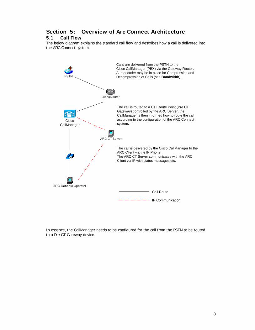
Section 5: Overview of Arc Connect Architecture 5.1 Call Flow The below diagram explains the standard call flow and describes how a call is delivered into the ARC Connect system.
Calls are delivered from the PSTN to theCisco CallManager (PBX) via the Gateway Router.A transcoder may be in place for Compression andDecompression of Calls (see Bandwidth).
The call is routed to a CTI Route Point (Pre CTGateway) controlled by the ARC Server, theCallManager is then informed how to route the callaccording to the configuration of the ARC Connectsystem.
The call is delivered by the Cisco CallManager to theARC Client via the IP Phone.The ARC CT Server communicates with the ARCClient via IP with status messages etc.
Call Route
IP Communication
CiscoCallManager
In essence, the CallManager needs to be configured for the call from the PSTN to be routed to a Pre CT Gateway device.
9
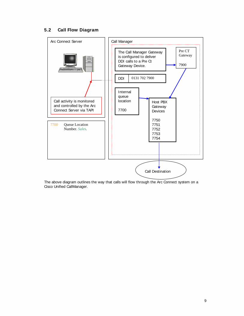
5.2 Call Flow Diagram
The above diagram outlines the way that calls will flow through the Arc Connect system on a Cisco Unified CallManager.
Call Manager
Pre CT Gateway
7900
Arc Connect Server
Call activity is monitored and controlled by the Arc Connect Server via TAPI
7700 Queue Location Number. Sales.
Call Destination
0131 702 7900 DDI
Host PBX Gateway Devices 7750 7751 7752 7753 7754
Internal queue location 7700
The Call Manager Gateway is configured to deliver DDI calls to a Pre Ct Gateway Device.

10
Section 6: CallManager Compatibility The ARC Connect system relies on the CallManager being a fully supported and tested version. If the CallManager is running a non-supported version, then certain areas of the ARC Connect system may not function correctly. In addition to this, the ARC Solutions support team will not support the system until the CallManager is upgraded/downgraded to a fully supported version. Therefore, it is essential that the CallManager and ARC Connect version is determined prior to the installation commencing. The latest ARC Connect Compatibility Matrix can be found on the Arc Enterprise Support Page on www.arcsolutions.com Please refer to this document for the latest updates on supported CallManager versions. 6.1 Calling Search Spaces and Partitions Calling Search Spaces (CSS) and Partitions are used within a CallManager system to limit the calling ability of the IP Phone users. Follow the below guidelines ONLY if Calling Search Spaces and Partitions are being used in the CallManager system. If this section is relevant to your CallManager system, it is recommended that the procedure below is followed before the ARC CTI Route Points and CTI Ports are created. If Calling Search Spaces and Partitions are being utilised, then you must ensure that all “ARC Controlled Devices” have the correct permissions. To do this, create a new Partition and Calling Search Space. Name both the CSS and Partition “ARC”: The “ARC” partition should be added to EVERY existing Calling Search Space configured The “ARC” Calling Search Space should have EVERY partition within it, including the newly created “ARC” partition. Once this work has been completed, all ARC CTI Route Points and CTI Ports need to have the “ARC” Calling Search Space and Partition assigned. The Client IP Phones do NOT need to have the “ARC” Calling Search Space and Partition.
Changing the configuration of Calling Search Spaces requires a Calling Search Space device reset. Therefore it is recommended that this work takes place out of business hours.

11
6.2 “ARC Controlled CTI Devices” and CallManager configuration “ARC Controlled CTI Devices” refers to the group of CTI Route Points and CTI Ports that the ARC Connect Server is configured to utilise. In order to maintain the integrity and stability of these devices, it is recommended that these devices be assigned to a dedicated Device Pool. The aim of this is to register these devices on the Publisher CallManager while all IP Phones in the cluster are registered to the Subscriber CallManager(s). Follow the below guidelines to achieve this: Create a new CallManager Group named “ARC” within the CallManager Administration. Select the order of the CallManagers so that the Publisher CallManager is the highest priority CallManager for this CallManager Group. Create a new Device Pool named “ARC” within the CallManager Administration. Assign the “ARC” CallManager Group to this Device Pool. Assign the “ARC” Device Pool to all “ARC Controlled CTI Devices”. Any IP Phones used as ARC Connect clients (Operator Consoles) should also be assigned to the “ARC” Device Pool. See the following pages for examples of CallManager Group configuration.
“ARC” Device Pool Contains “ARC Controlled CTI Devices” and the ARC Connect Client IP Phones. This Device Pool is using the “ARC” CallManager Group CCM Publisher
(Highest Priority)
CCM Subscriber
CCM PublisherCCM Subscriber
(Highest Priority)
“ARC” CallManager Group
“Default” CallManager Group
CallManager Group Configuration
“Default” Device Pool Contains all IP Phones within the system - excluding the ARC Client IP Phones.
- a two CallManager Cluster
In the above example, the CallManager cluster contains two CallManagers; one Publisher and one Subscriber. Typically, in a two CallManager cluster, the IP Phones will all be registered to the Subscriber CallManager.

12
The example above assumes that all IP Phones are registered to the Subscriber CallManager apart from the ARC Connect Client IP Phones. Therefore, the ARC Connect Client IP Phones and the ARC Controlled CTI Devices are all registered to the Publisher CallManager.
In the above example, the CallManager cluster contains three CallManagers; one Publisher and two Subscribers. Typically, in a three CallManager cluster, the IP Phones will be evenly registered across the two Subscriber CallManagers. The example above assumes that all IP Phones are evenly registered across the two Subscriber CallManagers apart from the ARC Connect Client IP Phones. Therefore, the ARC Connect Client IP Phones and the ARC Controlled CTI Devices are all registered to the Publisher CallManager via the “ARC” Device Pool.

13
6.3 CTIManager and Cisco TSP Configuration The CTIManager is a service that resides on all CallManager servers. This service provides the CTI information to the Cisco TSP. In effect, the CTIManager acts as a “TAPI Server” and the Cisco TSP acts as the “TAPI Client”. The CTI information is passed to the Cisco TSP client, which is installed on the ARC Connect Server machines. The CTI Manager can view the relevant CTI information for devices registered to any node on the CallManager cluster. When configuring the Cisco TSP on the ARC Server(s), the Primary CTI Manager should be set to the IP Address of the Publisher CallManager. This is recommended as the Publisher CallManager should be least heavily used CallManager within the cluster, and therefore the CTI information can be passed between the ARC Server and CallManager in the most efficient manner possible. The Secondary CTIManager should be configured as the IP Address of one of the Subscriber CallManagers.
When configuring the TAPI Users for the ARC Connect system, the following rules apply: The ARC Server TAPI User should have the following devices associated: “ARC Controlled CTI Devices”
IP Address of the Publisher CallManager
Please note that it is recommended that the CTI Manager Configuration should be performed using the IP address of the CTI Manager, NOT the DNS name of the servers. Therefore, the TAPI connectivity is not reliant on any DNS servers within the network.

14
Any Devices to be displayed within the Operator Busy Lamp Field (BLF) – if applicable All IP Phones that will be used as ARC Clients (Operator Console)

15
Section 7: CallManager/CTI Manager Resilience There are several components of an AVVID solution that can fail with the knock on effect of halting the ARC Connect system. These are outlined in detail below: 7.1 CTIManager service fails If the Primary CTIManager service fails, all of the ARC Controlled Devices will go “Out of Service”. This means that the TSP cannot control these devices. The Secondary CTI Manager should automatically take control of these devices and the downtime for the failover should be a minimum. (Assuming the Secondary CTIManager service is functioning correctly) This will mean that the CTI devices controlled by the ARC Server will be unavailable during this time as the devices failover. During this time, the ARC Client application will display a message stating “Your phone has gone out of service. You will not be able to make or receive calls at this time”. With the Operator Console, the Phone icon at the bottom of the application will display a red cross to indicate that the IP Phone is put of service. The message will remain on-screen until the second CTIManager re-opens the affected devices. When this has occurred, the icon will revert to its original appearance, and the on screen message will disappear. The application will now be functional again. 7.2 CallManager fails In the event of a CallManager failure (that is, the CallManager that the ARC Devices are currently registered to) the devices will failover to the next CallManager in the associated CallManager group. During this failover period, the CTI Devices controlled by the ARC Connect Server will be “out of service” and therefore will be unavailable. No calls will be able to enter the ARC Connect system during the failover period. If the CTI devices take longer 90 seconds to failover, then the ARC Server will automatically stop and start itself. This process will force the CTI devices back into service; however the client applications will lose connectivity to the ARC Server as soon as it stops itself. Once the ARC Connect Server is back on-line, the client applications can reconnect to the ARC Server. Also, the ARC Client IP Phones will failover to the next CallManager in the associated CallManager Group During this time, the ARC Client application will display a message stating “Your phone has gone out of service. You will not be able to make or receive calls at this time”. With the Operator Console, the Phone icon at the bottom of the application will display a red cross to indicate that the IP Phone is put of service. The message will remain on-screen until the second CTIManager re-opens the affected devices. When this has occurred, the icon will revert to its original appearance, and the on screen message will disappear. The application will now be functional again.
The Supervisor & Wallboard client applications do not communicate with the CallManager, only the ARC Server. Therefore, a CallManager/CTI Manager failure will not affect these applications.

16
Section 8: ARC Server Resilience In the event of an ARC Server failure, there are two ways to provide a resilient solution. 8.1 One ARC Server It is recommended that each solution have two ARC Connect Servers, as this will provide a resilient ARC Connect system. However, there may be a scenario where only one ARC Server is being deployed. In this scenario, resilience can be implemented by setting a Call_Forward_No_Answer on ALL ARC Pre CT Gateway and Internal Queue Location devices. (CTI Route Points) Configure these devices with a Call_Forward_No_Answer to a device that is not controlled by the ARC Connect Server. For example, the destination could be a simple IP Phone, or a Pilot Point number to be used in a hunt group. While this scenario will guarantee no loss of calls, the functionality offered by the ARC Connect system will not be available during this situation. This includes the reporting facility. 8.2 Two ARC Servers This is the recommended scenario for a resilient ARC Connect system. With this configuration, in the event of the Primary ARC Server failing, the Secondary ARC Server will automatically take over routing calls. The client applications need to follow the on screen prompt to connect to the Secondary ARC Server. See the Application Note for details on configuring ARC Server resilience with two ARC Servers.

17
Section 9: Arc LDAP synchronization 9.1 LDAP synchronization For the Operator Console, the Internal Directory is crucial. The Arc system provides the ability to synchronise with an external LDAP Source.
A separate Arc application, Arc LDAP Server connects to the customers’ LDAP contact database. It also reads the Arc contact database and synchronisescontact records between the two databases. The Arc LDAP Server can synchronize with one or many LDAP databases. These synchronized contact details are used by the Arc Console Operator application for directory lookups and call dialling. Arc does not store any data in the external LDAP database. The LDAP data source is read and data is stored into the Arc contact database for use by the Arc Connect application suite. Arc Connect version 3.1.x supports the synchronization of the following enterprise directories: IPlanet (Netscape/Sun Microsystems) Active Directory (Microsoft) LDAP synchronization enables external LDAP contacts to be read as Arc contacts. Arc Operators seamlessly integrate with a LDAP source, meaning all contact directory management are online and synchronized. As the LDAP Server records are synched, Arc Console Operator will see the latest details in Busy Lamp Field area.

18
Arc LDAP Solution provides a seamless link between the Arc LDAP Server and the LDAP database Server. This solution is useful for the Customers who have following conditions prevailing in their contact centres. Enterprise Directory is being used for the customers’ records or internal contacts or both. There are more than thousand internal extensions and it is difficult to keep the details of each internal contact in Excel or Access database. There is a need to keep the Operators updated about the latest details of the contacts. This can only be achieved by synchronization. LDAP Solution is especially beneficial for the customers who have a continuous update going on in their customers’ details or internal contacts’ details. 9.2 Data Preparation on LDAP Server Following are the considerations to prepare the data on LDAP database server before the synch takes place. Each record on LDAP Server must have a unique property. In case of iPlanet, DN is used as the unique property. Each internal record must have an internal extension. Once the record is added, then unique property must not be changed to avoid the orphan records. If the unique property is changed for any record, re-synch the records. It is advised to delete the record, and enter the record with new unique property. 9.3 Configuring Arc LDAP Synch Make sure the following before configuring the Arc Connect Components. LDAP Server is Up and running. User has a Network that fulfils the requirements given below. All the contacts’ records are updated on LDAP database server. Following are the tips for Arc configuration for the optimal synch between the LDAP database server and Arc LDAP Server. Rules: User can add more than one rule for synch. Always make rules that should fetch different records. Allowing one record to be filtered by more than one rule will effect the synch time. Re-scheduling should be used with caution. The time needed for re-scheduling depends upon the volume of the data. Enable “Monitor Change Notification” in container tab if immediate change is required to be reflected. If immediate reflection of change is not required then disable “Monitor Change Notification” and schedule re-synch for a complete update. It is advised not to use the “Approximate operator” while creating rules. Multiple Filters in one rule are handled with ‘AND’ operator, whereas Multiple Rules are handled with ‘OR’ operator.

19
Section 10: Remote SQL Server support 10.1 Configuration requirements With Arc Connect version 3.1x, the database backbone is based on Microsoft SQL Server / MSDE. In this scenario, it is preferable for some users to use an existing SQL Server “Cluster” that already exists on the network. One Arc Server can connect to the remote SQL Server for redundancy purposes. It is not supported for both Arc Servers (redundant solution) to connect to the same remote SQL Server Cluster. It is supported for each Arc Server to connect to different SQL Clusters if required. In order for Arc to successfully connect to a remote SQL Server, there are a few configuration requirements that need to be met. These are detailed below: The Arc Server “service” needs to have the “Log On” property set to a Domain Account. This account needs to be in the same Domain as the SQL Server This account needs to be configured as a “DBO” on the SQL Server for the Arc Configuration Database and the ArcLogDB These changes should be made BEFORE the Arc Databases are created via the Administration Application. At the time of installation of the Arc Server, the name or IP Address of the Remote SQL Server Cluster must be specified 10.2 Additional Configuration required for Arc v4.1.3sr2 onwards Arc v4.1.3sr2 incorporates new functionality, which require extra steps to be taken to enable the Remote SQL Server support: From the Arc Server, browse to C:\Program Files\Arc\Arc Connect\Phonetic N.B. For Arc v4.1.4 onwards, the above location is changed to C:\Program Files/Arc/Arc Connect/DLL Find the “MetaphoneCOM.dll” and “XPMetaphone.dll”. Copy both of these files to the folder where the Arc Databases are stored on the SQL Server N.B. For Arc v4.1.4 onwards, these files should be copied to a SubFolder in the SQL Database folder called “DLL”. This folder should be created manually Next, on the SQL Server, Launch SQL Enterprise Manager, and expand the “Master” Database Expand the “Extended Stored Procedures” and locate the xp_metaphone procedure Select the properties of this procedure, and change the path to the location of the XP_Metaphone.dll file that has been copied to the SQL Server
Next, on the Arc Server, browse to C:\Winnt\System32 folder

20
Locate the msvcr70.dll file, and copy this to the “System32” folder on the SQL Server
The Arc “Hot Standby” feature available from v4.1.4 onwards is NOT supported in a Remote SQL Server environment. In order to use “Hot Standby”, the Arc Servers must be using a locally installed version of SQL Server

21
Section 11: Operator Busy Lamp Field Limitations According to Cisco Unified CallManager Design Guidelines, there is a device association limit of 2500 devices per server per user. This figure is based on the CallManager being a dual-processor server. If the CallManager servers are the single processor version, this limit is reduced to 800 devices The Arc Connect system uses the Cisco TSP (TAPI) for Line State (or Busy Lamp Field). In order for this to work, all devices on which BLF status is required need to be associated to the Arc Server “User” on the CallManager. As per the statement above, the number of devices that are required are limited. N.B. It is worth noting that this limitation of 2500 devices includes the CTI Route Points/CTI Ports used by the Arc Server Traditionally, the Operators handle calls in a “fire and forget” manner where they simply transfer a call and are unconcerned about the current state of the target extension. If the target extension is busy or unmanned, then it is usually the responsibility of that phone user to ensure the handset is forwarded correctly. In the scenarios where a forward is not in place, then the call reverts back to the Console Operator, where they can use the Camp-On feature, or transfer the call to another extension. Usually, Enterprise Console Operators will not take messages for individual phone users. Although no more than 2500 BLF Devices are supported per Arc Server, there is no limit to how many Directory Entries that are supported with the Arc Operator. It is possible for users to have over 5000 (for example) contacts in their directory, which the Operators use to transfer calls to. In this scenario, Line State is not available for the all of the extensions; however this is not traditionally seen as an issue An example of such a configuration is below: The Customer has 4000 phones in their Cisco IPT Environment. There are 5 Arc Operator Consoles running on a single Arc Server We know that it is not possible for the Arc Server to have all 4000 devices in the BLF. Therefore, the customer has 2 options: Not to use the Operator BLF feature To specify which extensions the Operator would like to see in the BLF (using the “Directory Group” configuration screen on the Arc Server) Whichever decision is made regarding the BLF, it is still possible to have all 4000 contacts listed in the Operator Internal Directory. There is no limit to the number of contacts that are displayed, the limitation is purely related to Line State/BLF
22
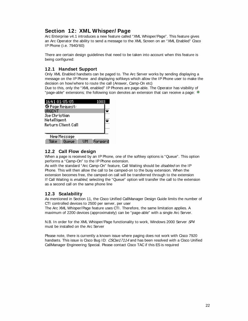
Section 12: XML Whisper/Page Arc Enterprise v4.1 introduces a new feature called “XML Whisper/Page”. This feature gives an Arc Operator the ability to send a message to the XML Screen on an “XML Enabled” Cisco IP Phone (i.e. 7940/60) There are certain design guidelines that need to be taken into account when this feature is being configured: 12.1 Handset Support Only XML Enabled handsets can be paged to. The Arc Server works by sending displaying a message on the IP Phone and displaying softkeys which allow the IP Phone user to make the decision on how/where to route the call (Answer, Camp-On etc) Due to this, only the “XML enabled” IP Phones are page-able. The Operator has visibility of “page-able” extensions; the following icon denotes an extension that can receive a page:
12.2 Call Flow design When a page is received by an IP Phone, one of the softkey options is “Queue”. This option performs a “Camp-On” to the IP Phone extension. As with the standard “Arc Camp-On” feature, Call Waiting should be disabled on the IP Phone. This will then allow the call to be camped-on to the busy extension. When the extension becomes free, the camped-on call will be transferred through to the extension If Call Waiting is enabled, selecting the “Queue” option will transfer the call to the extension as a second call on the same phone line 12.3 Scalability As mentioned in Section 11, the Cisco Unified CallManager Design Guide limits the number of CTI controlled devices to 2500 per server, per user The Arc XML Whisper/Page feature uses CTI. Therefore, the same limitation applies. A maximum of 2200 devices (approximately) can be “page-able” with a single Arc Server. N.B. In order for the XML Whisper/Page functionality to work, Windows 2000 Server SP4 must be installed on the Arc Server Please note, there is currently a known issue where paging does not work with Cisco 7920 handsets. This issue is Cisco Bug ID: CSCse17114 and has been resolved with a Cisco Unified CallManager Engineering Special. Please contact Cisco TAC if this ES is required

23
Section 13: Personal Call Park (PCP) Personal Call Park (PCP) is a feature introduced in Arc Enterprise v4.1. This feature is an extension of standard Call Park. With standard Call Park, a “tannoy” style system is used to inform the target contact that “A call is parked on Bay 2000” PCP extends this feature. When this is being used, the tannoy system is simply used to inform the target contact that “A call is parked”. The caller then dials into the PCP system, and the system automatically connects the caller based on the calling extension PCP has 2 modes of operation: “Recognised” number and “Unrecognised” number 13.1 “Recognised” number When the Operator answers the call and makes the decision to park the call, the Operator selects the contact that call is to be parked for. For example “Bennie Grant”. “Bennie Grant” has an extension number of 1000 When “Bennie Grant” calls into the PCP system, it looks at the number that is calling into the system. If “Bennie Grant” is calling into PCP from his own extension (1000) the PCP system recognises this and automatically connects the call 13.2 “Unrecognised” number As per the example in Section 13.1, the call is parked for “Bennie Grant”. However, in this occasion, “Bennie Grant” is not at his desk, and dials into the PCP system from another extension (e.g. Extension 1235) In this scenario, there is no call parked for extension 1235 (the call is parked for extension 1000). Because the PCP system cannot match a call for extension 1235, a tone is played through the handset When this occurs, “Bennie Grant” enters his own extension number (1000), the PCP checks that this extension DOES have a call parked for it, and therefore connects the call 13.3 Considerations The PCP system can be used in many specific environments. The system has the advantage of only having one number for the users to remember (as opposed to the Operator tannoying out the Park Bay number). In particular, the PCP feature is a very powerful tool in shop floor and hospital environments The numbers that are dialled to enter the PCP system are configured as CTI Ports on the Cisco Unified CallManager The PCP system heavily relies on the accuracy of the Arc Contacts Directory, as it is this Directory that is used when the Operator parks a call for a specific contact. Therefore, it is imperative that the Directory is maintained accurately.
24
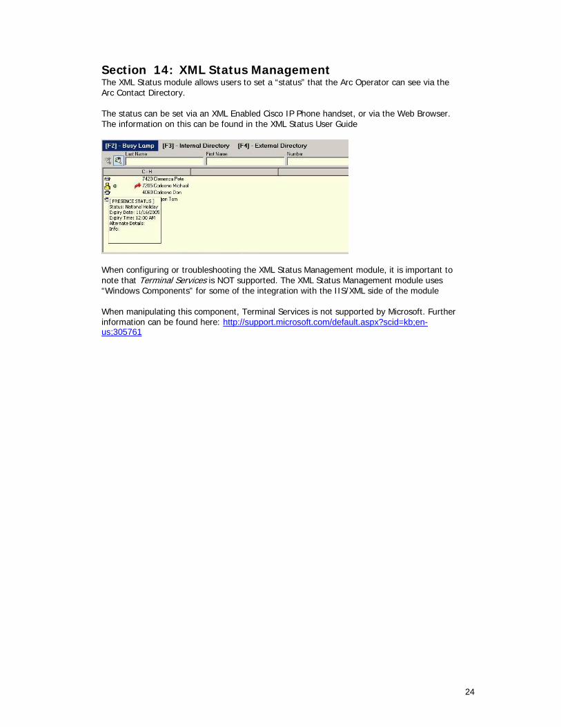
Section 14: XML Status Management The XML Status module allows users to set a “status” that the Arc Operator can see via the Arc Contact Directory. The status can be set via an XML Enabled Cisco IP Phone handset, or via the Web Browser. The information on this can be found in the XML Status User Guide
When configuring or troubleshooting the XML Status Management module, it is important to note that Terminal Services is NOT supported. The XML Status Management module uses “Windows Components” for some of the integration with the IIS/XML side of the module When manipulating this component, Terminal Services is not supported by Microsoft. Further information can be found here: http://support.microsoft.com/default.aspx?scid=kb;en-us;305761

25
Section 15: Unity Voicemail Integration Cisco Unified CallManager has the ability to configure a “Voicemail Prefix”. This means that from anywhere within the CallManager system a prefix can be dialled to enter a specific mailbox. For example, if the prefix is “*”, then dialling *1002 will take the caller directly to the mailbox of extension 1002 More details on this functionality can be found here: http://www.cisco.com/en/US/partner/products/sw/voicesw/ps556/products_tech_note09186a00800dea82.shtml 15.1 Integrating with the Arc Console Operator The Arc Console can use the “Voicemail Prefix” functionality within the Cisco Unified CallManager to transfer calls directly to a Contacts mailbox. To configure Voicemail Access with the Arc Operator Console, follow the steps below: Configure the “Voicemail Prefix” using the Cisco whitepaper (URL above) From the Arc Operator Console, select Options>Preferences Under the “General” tab, change the “Voicemail Prefix” setting to whichever the prefix is configured as on the CallManager (typically, this is set to *)
Press Apply, the press OK Now, when the Operator is connected to a call, the right-click menu will display an additional option – “Transfer to Voicemail”.

26
15.2 How this works When the Operator selects the “Transfer to Voicemail” option, the Arc Server takes the extension number of the selected contact, and prefixes the number with the Voicemail Prefix number that has been configured. The call is then blind transferred to this extension. The Arc Server has the dependency that the Voicemail Prefix functionality is configured on the Cisco Unified CallManager
27
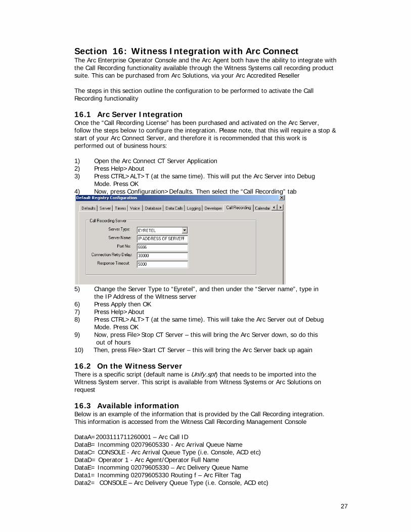
Section 16: Witness Integration with Arc Connect The Arc Enterprise Operator Console and the Arc Agent both have the ability to integrate with the Call Recording functionality available through the Witness Systems call recording product suite. This can be purchased from Arc Solutions, via your Arc Accredited Reseller The steps in this section outline the configuration to be performed to activate the Call Recording functionality 16.1 Arc Server Integration Once the “Call Recording License” has been purchased and activated on the Arc Server, follow the steps below to configure the integration. Please note, that this will require a stop & start of your Arc Connect Server, and therefore it is recommended that this work is performed out of business hours: 1) Open the Arc Connect CT Server Application 2) Press Help>About 3) Press CTRL>ALT>T (at the same time). This will put the Arc Server into Debug Mode. Press OK 4) Now, press Configuration>Defaults. Then select the “Call Recording” tab
5) Change the Server Type to “Eyretel”, and then under the “Server name”, type in the IP Address of the Witness server 6) Press Apply then OK 7) Press Help>About 8) Press CTRL>ALT>T (at the same time). This will take the Arc Server out of Debug Mode. Press OK 9) Now, press File>Stop CT Server – this will bring the Arc Server down, so do this out of hours 10) Then, press File>Start CT Server – this will bring the Arc Server back up again 16.2 On the Witness Server There is a specific script (default name is Unify.spt) that needs to be imported into the Witness System server. This script is available from Witness Systems or Arc Solutions on request 16.3 Available information Below is an example of the information that is provided by the Call Recording integration. This information is accessed from the Witness Call Recording Management Console DataA=2003111711260001 – Arc Call ID DataB= Incomming 02079605330 - Arc Arrival Queue Name DataC= CONSOLE - Arc Arrival Queue Type (i.e. Console, ACD etc) DataD= Operator 1 - Arc Agent/Operator Full Name DataE= Incomming 02079605330 – Arc Delivery Queue Name Data1= Incomming 02079605330 Routing f – Arc Filter Tag Data2= CONSOLE – Arc Delivery Queue Type (i.e. Console, ACD etc)

28
Section 17: AntiVirus support on an Arc Server There are many different AntiVirus products that are supported on an Arc Connect Server. Typically, the most commonly used products are McAfee VirusScan and Norton AntoVirus Both of these products are supported, although any AntiVirus program is supported on the Arc Server, as long as it is configured as below: 17.1 Exclusions It is important that the AntiVirus product supports “Exclusions”. This is the ability for the user to specify specific files and/or folders that will NOT be scanned by the AntiVirus program. The following exclusions should be set when using AntiVirus on an Arc Server File Name(s) File Location Use ICDLog001(x).txt \\Program Files\Arc\Call Connect\Server These are the main
trace files created by the Arc Server
ICDRun.log \\Program Files\Arc\Call Connect\Server\Logs This is the Runtime log created by the Arc Server
ICDInit.log \\Program Files\Arc\Call Connect\Server\Logs This file is created as part of the Arc Server initialisation process
All files in “Arc Data” \\Arc Data This folder is where the Arc Databases are located
SVSErrs.log \\Program Files\Arc\Call Connect\Voice Server\Logs
This is the main trace file created by the Arc Voice Server
CiscoTSPLog001(x).txt \\Temp\Cisco\Trace This is where the Cisco TSP Trace files are located
N.B. The “File Locations” and “File Names” may be changed by your Arc Connect Administrator. The files in the above table are constantly being written to and updated during a standard production day with an Arc Server. Due to this, these files are permanently being accessed – an AntiVirus “Scan on access” policy for these files will mean that the files are constantly being scanned for Viruses. This will in turn slow down the operation of the Arc Server. Therefore, excluding these files from being continuously scanned will allow the Arc Server to function as expected.
29
Section 18: Supported Remote Access Applications As part of the support provided by the Arc Partner or Arc Solutions directly, remote access to the Arc Connect Server is often required. There are various remote access products available in the marketplace. Of these, only certain applications are supported with the Arc Connect Server. The supported Remote Access Applications are below: Real VNC Symantec pcAnywhere All of the above applications should be installed as per the manufacturers’ recommendation. NOTE: The use of session based remote access applications such as Remote Desktop (RDP) and Terminal Services (TS) are not supported. This is due to known issues that can occur with the Cisco TSP & Wave driver as well as service issues with the Arc Voice Server.

30
Section 19: Calendar Integration 19.1 Introduction This feature will allow console users to see, at a glance, the calendar activities or ‘availability’ of a staff member using simple user interface features and design. In addition an operator will be able to open up a contact’s Outlook Calendar to see more information. 19.2 Functional Details 19.1.1. System Integration details The integration with Outlook is conducted at the client level. In order to use the functionality the individual Console Operator will need a MS Outlook client running on their PC. A dll file is used to link the 2 applications together. The column display is based on the generically available free/busy information, the same information as is available when scheduling a meeting within Outlook. The calendar display option (CTRL+L) relies on the permissions given to the individual operators’ Outlook client, for example if the operator does not have the permission to open up an individual calendar they will have a message displayed to that effect. The Console application will only be able to view a users calendar information (view calendar) if the user has enabled a Reviewer privilege to allow the operator to see their calendar information.
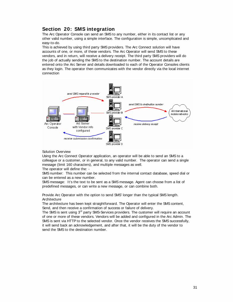
31
Section 20: SMS integration The Arc Operator Console can send an SMS to any number, either in its contact list or any other valid number, using a simple interface. The configuration is simple, uncomplicated and easy-to-do. This is achieved by using third party SMS providers. The Arc Connect solution will have accounts of one, or more, of these vendors. The Arc Operator will send SMS to these vendors, and in return, will receive a delivery receipt. The third party SMS providers will do the job of actually sending the SMS to the destination number. The account details are entered onto the Arc Server and details downloaded to each of the Operator Consoles clients as they login. The operator then communicates with the vendor directly via the local internet connection
Solution Overview Using the Arc Connect Operator application, an operator will be able to send an SMS to a colleague or a customer, or in general, to any valid number. The operator can send a single message (limit 160 characters), and multiple messages as well. The operator will define the: - SMS number: This number can be selected from the internal contact database, speed dial or can be entered as a new number. SMS message: It’s the text to be sent as a SMS message. Agent can choose from a list of predefined messages, or can write a new message, or can combine both. Provide Arc Operator with the option to send SMS’ longer than the typical SMS length. Architecture The architecture has been kept straightforward. The Operator will enter the SMS content, Send, and then receive a confirmation of success or failure of delivery. The SMS is sent using 3rd party SMS-Services providers. The customer will require an account of one or more of these vendors. Vendors will be added and configured in the Arc Admin. The SMS is sent via HTTP to the selected vendor. Once the vendor receives the SMS successfully, it will send back an acknowledgement, and after that, it will be the duty of the vendor to send the SMS to the destination number.

32
The architecture remains the same. CT Server and Admin application will interact will Configuration Database as before. Operator, as a client application, will get data from CT Server. At the time of sending the SMS, Operator application will call SMS API’s function and pass the data to it. 20.1 Protocols This solution currently makes use of HTTP/HTTPS protocol for working. So, it is compatible with all those vendors in the market that provide HTTP/HTTPS solutions. 20.2 Tenancy This SMS feature will work in a multi-tenant environment. Arc’s solution works in a way that all the contacts are divided into different Regions. These different Regions are dealt differently. Each Region can be assigned an SMS vendor. In the case that no vendor is assigned to a Region, the system will use the default vendor to send the SMS. 20.3 Communities For multi tenant systems, a default vendor can be able to be set for a community.

33
Section 21: CUPS Integration Part of the Arc presence strategy is to incorporate Cisco’s native presence solution. Currently Cisco provides presence via a product called Cisco Unified Presence Server (CUPS). Cisco presence features will be available on all Cisco and Arc product editions. Please note that TLS security is not currently supported. This will be available at a later date. This project will specify the client protocols that will be used to transport data between the client and the Arc CUPS server. 21.1 Arc Architecture Overview Based on directives and guidelines from Cisco, Arc will provide a server based solution to communicate with the CUPS (see diagram below).
TCP (Port
1859
)TCP (Port 1863)

34
The new Arc CUPS server will connect directly to the Cisco CUPS server using SIP SIMPLE protocol extensions. The Arc Operator will connect directly to the Arc CUPS server to manage presence status procurement. A pre-requisite for running the Arc CUPS Server will be using Microsoft dot net framework 2 Service Pack 1. This will be automatically installed if not present prior to the installation. The configuration of the Arc CUPS server will be stored in an XML formatted file with the same name as the Arc CUPS server executable and with a .config extension i.e. “Cisco Presence Server Plug-in.exe.config”. The Arc Cups Server needs to be able to communicate with the Cisco CUPS Server and also with all the Arc Operator clients. The important properties needed for this communication are:-
XML Property Default Value Description CupsIP <BLANK> IP Address of the Cisco Unified Presence Server CupsTCPPort 5060 Port number of the Cisco Unified Presence Server
when not using TLS (Transport Layer Security) CupsUsername <BLANK> The Username normally used to access the CUPS
Admin utility. CupsPassword <BLANK> The Password normally used to access the CUPS
Admin utility. Realm <BLANK> SIP authentication requires specific realm (a
protection domain). In other words, the realm is used to authenticate and manage SIP communication. When this property is <BLANK> the server will use the IP address used to connect to the Cisco Unified Presence Server i.e. the CupsIP property (for the primary server).
sipLocalIP localhost This setting specifies the IP address to where the Cisco Unified Presence Server will send replies to. It defines the domain for the SIP UserAgent.
ServerIP <BLANK> The server IP address for the socket to listen on for client connections – most servers contain multiple network cards and this setting allows for a particular network to be specified.
TcpPort 1863 The server Port number to listen on for client connections.
MaxPooledThreads 5 The incoming client requests are processed in a multi-thread environment. Hence, five client requests can be processed simultaneously. A higher number of simultaneous requests will cause requests to be queued. Under heavy loads, this setting can increase the number of threads in the threadpool to process requests thus reducing the number of requests that are queued. Increasing this value increases resources required by the threadpool.
The Arc operator will be responsible to maintain connection with the Arc CUPS server, including reconnection after losing connection. The location of the Arc CUPS server can be downloaded using the new Arc server developer interface API changes (see section A.2). If the presence server name (TICDServerInformation.Presence_Server_Name) is blank then the CUPS server has been disabled. If the presence server name is ‘localhost’ the operator application will use the same IP address as is used to connect to the Arc server.

35
All messages to and from the Arc CUPS server will be managed as XML data. After registration with the Arc CUPS server, presence status information for users can be obtained. It is assumed that the operator application will validate the following before enabling CUPS presence integration: The Arc server has a valid Cisco presence server license The operator has a valid presence user session license assigned (following an Arc server login success) The Arc CUPS server is available and fully active.

36
Section 22: Consolidated Presence 22.1 Presence Integration The use of corporate presence applications has increased and is now used as commonplace in most businesses. With this fact considered, there has become a need to provide support, within the operator, for some of the industry heavyweight presence applications. Currently the Arc operator supports the following presence sources: Phone status (Busy Lamp) Cisco Unified Presence Server (CUPS) Microsoft Outlook Calendar (free\busy) Microsoft OCS/LCS Arc Presence Contact notes 22.1.1. Presence Preferences A new default presence display preference will be created in the new ‘Presence’ tab. This will allow the operator to select their preferred default presence status source. This selection will define the presence status to be displayed in the default presence status column display in the Internal Directory [F3] and External Directory [F4]. A new group box will be added called ‘Default Presence Display’ and will contain the following radio dialog options: Arc Presence Status Microsoft Presence (OCS/LCS) Cisco Unified Presence Server (CUPS) None This preference will be stored.
Note Default presence status options will be disabled if specific presence licenses are not available (in this example the default presence will default to None). The operator will also check the licenses on successful login to ensure that a licensed default presence source is selected.
Note A user’s Cisco profile identifier (profile name) will be used to manage the contact synchronization between the Console application and CUPS.
22.2 Licensing For all PEL’s, if the Arc server grants the Arc operator a presence session license and the relevant Microsoft/Arc/CUPS server license has been activated then Cisco Presence status features and functionality will be activated for the Arc operator. Otherwise the Cisco Presence status feature will be disabled.

37
Section 23: Serial Calling Serial Calling is a traditional TDM feature that allows an incoming call to be transferred to multiple destinations in consecutive order, without recourse to the transferring party. This feature has been enabled through the use of the Conference facility on the CallManager. Once the operator has started the Serial Call, the call is maintained on a CTI Port within the Service Queue, with each destination being first called as an enquiry call from the CTI Port, and then once the call is connected a conference is created between the caller, the CTI Port and the destination. When the destination hangs up the caller is placed on hold at the CTI Port, and the next enquiry call is made etc etc. If FAC or CMC codes are in use for any of the destinations required by the serial call, only the default codes configured in the Arc Admin application will be used.

38
Section 24: Other Considerations 24.1 Codecs It is imperative that this section is understood fully before an ARC Connect implementation commences. When using an ARC Connect system in a centralised environment, there are some considerations that must be taken into account. CTI Ports are relied on for the correct working of the ARC Connect system. CTI Ports do not support the G729 codec. Therefore, in a centralised environment where the G729 codec is being used across WAN links, a transcoder must be installed on the Central Site where the ARC Server is located. A transcoder takes the output stream of one codec (compression type) and converts it to another compression type. This will mean that if a call goes across the WAN link to an IP Phone as a G729 call; the call will be converted back to G711 when it comes back to the Central site. The figures below illustrate a typical call flow, and show where and why the transcoder is needed: Figure 1: Call enters the system
1: Call is received from PSTN 2: Call is routed from the Pre CT Gateway to the Host PBX Gateway 3: The Operator Console client now has visibility of the call in the queue At this point, the call is on the Host PBX Gateway and is in the queue waiting to be answered. The Host PBX Gateway devices are registered to the CallManager in the remote site. Therefore the call has a codec of G711 at this point.
PSTN 1
2
3
Remote Site
Central Site
G711 Codec
G729 Codec
CallManager
SD
Media Converter
LINK PWR LINK
5VDC. 1A_ __ __ +
UP LINK
RX
TX
Transcoding Resource

39
Figure 2: Remote Operator Requests the call
4: The Operator Console requests the call
Once the Operator Console requests the call, the call will be delivered to the Operator extension. As the extension is in the remote site with a G729 codec, the call will be changed to the G729 codec as soon as it goes across the WAN link. Figure 3: The Operator Console answers the call
5: The Operator Console is talking to the caller Now that the Operator is talking to the caller, and the Operator is on the remote site, the call has now been converted to the G729 codec.
Remote Site
Central Site
SD
Media Converter
LINK PWR LINK
5VDC. 1A_ __ __ +
UP LINK
RX
TX
Transcoding Resource
G711 Codec
G729 Codec
4
Remote Site
G729 Codec
5
PSTN

40
Figure 4: The Operator Console puts the call on hold
6: The Operator Console requests the call to be put on hold When the Operator Console requests to put the call on hold, the call is redirected back to the ARC Server, to be put on hold on a Service Queue Device (CTI Port). At this point, the transcoder converts the call back to the G711 codec. If the call is still G729 when it reaches the Service Queue, the CallManager will disconnect the call.
The same theory applies if the call is being transferred, parked, or camped on. The figure illustrated in Appendix 1 shows a typical configuration where CallManagers and ARC Servers are hosted on one site along with an ARC Connect Client. There is also an ARC Connect Client connected to the ARC Server across a WAN link.
PSTN
6
Remote Site
Central Site
G711 Codec
G729 Codec
CallManager
SD
Media Converter
LINK PWR LINK
5VDC. 1A_ __ __ +
UP LINK
RX
TX
Transcoding Resource

41
24.2 Cisco CTI Scalability The Cisco Unified CallManager has various CTI Scalability limitations that must be taken into account when designing your Arc Enterprise Operator Console solution. These limitations are summarised below. For further information, please reference your Cisco SRND For each user that is created on the CUCM, there is a maximum of “2500 devices” that can be associated. This means that each user configured for the Cisco TSP can have a maximum of 2500 devices, and must be configured to point to 2 specific CTI Managers. Each node in the CallManager cluster can support a maximum of 2,500 “CTI Controlled Devices” This is reduced to 800 CTI Controlled Devices if the CallManager cluster is running on MCS-7835 platforms or below If your CUCM is integrated with an LDAP Source (i.e. Active Directory or Sun iPlanet), this limitation is reduced to 850 devices – irrespective of the hardware platform the CallManagers reside on Please note that this limitation only exists with CallManager 4.3 and below. With CallManager v5.x onwards, this limitation is removed, and the standard “2500 devices” or “800 devices” exists (based on your hardware platform) There is a limitation of a maximum of 10,000 devices that can be associated to CTI Users “Cluster Wide”. This limitation is reduced to 3,200 if the CallManager cluster is running on MCS-7835 platforms or below Example

42
24.3 Bandwidth Location-based Call Admission Control may be implemented to control the bandwidth usage across the WAN. A maximum amount of bandwidth may be configured for calls to and from each remote location. When an ARC controlled CTI Route Point or CTI Port is created, the location should be set to None. This will effectively ensure that no bandwidth limits will apply to that device. Regions may be used in conjunction with Locations, to define the type of compression used on a particular link. Calls routed across a LAN typically use the G711 codec, with each call using 80Kb/sec of bandwidth. Calls routed across the WAN may use the G729 codec, which reduces the bandwidth requirement of a call to 24Kb/sec. If different compression types are to be used to reduce the amount of bandwidth needed across the WAN, then a transcoder will be needed (See Codec Considerations - above) In addition, further bandwidth is used by IP communications between the ARC CT Server and the Console Operator. To calculate the bandwidth required by these functions, see the link to the Bandwidth Calculator (See the Bandwidth Calculator link on the final page).
43
24.4 Arc Connect Client Applications and Shared Lines Arc Connect Client applications (Arc Agent, Arc Operator etc.) do NOT support shared lines. A shared line is where multiple IP Phones have the same directory number. Please note, this is a limitation with the Cisco Unified CallManager CTI Interface (the Cisco CTI Manager service) If a user is to use an Arc Client application, the extension that the user logs in to MUST be a unique number. If an IP Phone has multiple, this IS supported, as long at the following criteria is met: At least one line on the handset is NOT a shared line The “Arc User” line/non-shared line is the Primary line on the handset (the first number in the list) The user is not logging into the Arc Application using the Shared Line 24.5 Arc Connect TCP Ports The Arc Connect Suite uses a series of TCP/IP Ports to communicate between applications. In large networks (often involving a WAN) there could be a need to prioritise these ports across the network switches. In this scenario, the following ports should be prioritised: TCP/IP Port Use 1859 This is the Port used by the ARC Connect
system to communicate across a LAN between the ARC Server and the client applications
11859 This is the Port used by the ARC Connect service to communicate with the ARC Connect Server
6550 This is the port used by the Arc XML Whisper Page service
6600 This is the port used by the Cisco IP Phones for the Arc Server to push RTP Audio data for playback – i.e. the Alert Tone used with the XML Whisper Page service
1659 This is the Port used by the ARC Connect Voice Server to communicate with the ARC Connect Server
11659 This is the port used by the Arc Voice Server service to communicate with the Arc Voice Server
80 This is the IP Port used by the Arc XML Status Management service – this is hosted on IIS (on the Arc Server) and listens for HTTP requests coming from the IP Phone, Web Browser and to send requests to IP Phones on the same port
This includes the same DN, but in different partitions – this is also not supported
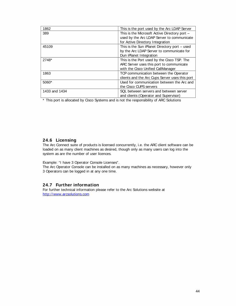
44
1862 This is the port used by the Arc LDAP Server 389 This is the Microsoft Active Directory port –
used by the Arc LDAP Server to communicate for Active Directory Integration
45109 This is the Sun iPlanet Directory port – used by the Arc LDAP Server to communicate for Dun iPlanet Integration
2748* This is the Port used by the Cisco TSP. The ARC Server uses this port to communicate with the Cisco Unified CallManager
1863 TCP communication between the Operator clients and the Arc Cups Server uses this port
5060* Used for communication between the Arc and the Cisco CUPS servers
1433 and 1434 SQL between servers and between server and clients (Operator and Supervisor)
* This port is allocated by Cisco Systems and is not the responsibility of ARC Solutions 24.6 Licensing The Arc Connect suite of products is licensed concurrently, i.e. the ARC client software can be loaded on as many client machines as desired, though only as many users can log into the system as are the number of user licences. Example: “I have 3 Operator Console Licenses”. The Arc Operator Console can be installed on as many machines as necessary, however only 3 Operators can be logged in at any one time. 24.7 Further information For further technical information please refer to the Arc Solutions website at http://www.arcsolutions.com

45
Section 25: Appendixes Appendix 1: Sample Topologies The following topology examples are shown in Appendix 1: Single Site Topology Single Site Resilient ARC Server Topology Centralised ARC Server with Local and Remote Clients Multi – Cluster Scenario A1.1 Single Site Topology
CiscoCallManager
Cluster
Call RouteIP Communication
In the example above, the ARC Server and the Client machines are on the same LAN as the CallManager servers. There are no remote ARC users, or IP Phones. This topology is showing the following characteristics: Resilience is configured using Call Forward No Answer to Pilot Point Group, IP Phone or other device. Client machines are on the same LAN as the ARC Server and CallManager Servers. Typically, the ARC Connect CT Server and the ARC Voice Connect Server reside on the same hardware platform
46
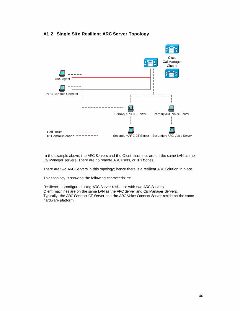
A1.2 Single Site Resilient ARC Server Topology
CiscoCallManager
Cluster
Call RouteIP Communication
In the example above, the ARC Servers and the Client machines are on the same LAN as the CallManager servers. There are no remote ARC users, or IP Phones. There are two ARC Servers in this topology; hence there is a resilient ARC Solution in place This topology is showing the following characteristics: Resilience is configured using ARC Server resilience with two ARC Servers. Client machines are on the same LAN as the ARC Server and CallManager Servers. Typically, the ARC Connect CT Server and the ARC Voice Connect Server reside on the same hardware platform

47
A1.3 Centralised ARC Server with Local and Remote Clients
In the example above, there is an ARC Server and some client machines are on the same LAN as the CallManager servers. There are also some client machines on a remote site, which is in a G729 region. This topology is showing the following characteristics: Resilience is configured using Call Forward No Answer to Pilot Point Group, IP Phone or other device. Due to the fact that the G729 codec is being used for the remote site, a transcoding resource is installed on the central site, as this is where the CallManagers are located, and therefore where the CTI Ports are registered. Therefore, when the client in the remote site handles the call, it is using the G729 codec; however as soon as the call is routed back to the central site, the call is changed to the G711 codec. As the G711 codec is being utilised within the LAN, the local clients are not affected.

48
A1.4 Multi – Cluster Scenario
CiscoCallManager
Cluster
Call RouteIP Communication
WAN
Site 1 Site 2
CiscoCallManager
Cluster
ARC CT Servers on each site act as independent systems. Each site may have its own Primary and Back-up ARC CT Servers. This will determine the level of resilience as previously shown An ARC Server cannot communicate with multiple clusters, only with multiple nodes within one cluster. Therefore, in the example above where there are two clusters, ARC Servers will be needed at each site.

49
Appendix 2: Calculations A2.1 Device Weightings CallManager device weightings are calculated depending on the device type and the BHCA (Busy Hour Call Attempts) that can be expected. The algorithms to calculate device weightings are dependant on the CallManager software version. Please refer to you Cisco documentation for details. When calculating device weightings for ARC Connect, the table below will assist in which devices you need to account for:
Arc Device Name CallManager Device Type Description/Use BHCA
Pre CT Gateway CTI Route Point
The Pre CT Gateway is used for routing calls from the PSTN into the ARC Connect system.
Every call that is routed into the ARC Connect System goes via a Pre CT Gateway. Your BHCA here should be approx the BHCA for the DDI/DID in question
Host PBX Gateway CTI Port Once a call has reached the Pre-CT Gateway, the ARC Server informs the CallManager to move the call to a Host PBX Gateway device. The Host PBX Gateway is used for queuing calls in the ARC system.
Once the call has reached the Pre CT Gateway, the call is immediately moved to Host PBX Gateway device. The BHCA here should be calculated based on number of Host PBX Gateway Devices and total calls expected into the ARC Server (via the Pre CT Gateway)
Queue Location CTI Route Point
Each call queue (Operator Console, Voice Session etc) configured has an internal queue location. These are used for internal workings by the ARC Connect Server.
These devices are rarely used in a production environment. You would anticipate the BHCA for these devices to be very low.
Service Queue Devices (Operator Console Only)
CTI Port The Service Queue devices are used by the Operator Console application to hold, transfer and camp calls on.
Each time an Operator holds, transfers or camps on a call, a Service Queue Device is used. The BHCA for these devices will

50
depend on the BHCA expected through the Operator Console.
Call Park Devices (Operator Console Only)
CTI Port The Call Park devices are used by the Operator Console to park calls.
Each time an Operator parks a call, a Call Park Device is used. The BHCA for these devices will depend on the BHCA expected through the Operator Console and the utilisation of the Call Park feature.
Static Voice Ports CTI Port These devices are used for recording messages to be used in the Voice Connect product (i.e. AutoAttendant)
These devices are used for recording messages only. No calls will be routed through these CTI Ports.
A2.2 ARC Device Provisioning When planning the installation of an ARC Connect system, thought must be put into calculating the number of “ARC Controlled CTI Devices” to be configured on the CallManager. The below information will assist in making those decisions Pre Ct Gateway For each DDI/DID that is to be routed into the ARC Connect Server, a Pre CT Gateway needs to be configured. Host PBX Gateway These devices are used for queuing calls that have not yet been answered. The recommendation is that there is the same amount of Host PBX Gateway Devices as there are PSTN lines coming into the ARC Connect system. Queue Location For each Console and Voice queue configured in the ARC Connect system, a queue location is required. Service Queue The Service Queue is used by the Operator Console to Hold, Transfer and Camp On calls. The recommendation is 4 – 6 Service Queue devices are configured per Operator Console user. These devices are only used with the Operator Console. If the Operator Console is not going to be installed, then these devices need not be created.
If there will be a 30 line PRI coming into the ARC Connect system, then create 30 Host PBX Gateway devices. This will mean that the ARC Server will be able to queue as many calls as there are physical phone calls.

51
Call Park Devices The Call Park Devices are used for the Operators to park calls. It is recommended that 3 Call Park devices are configured per Operator Console user. These devices are only used with the Operator Console. If the Operator Console is not going to be installed, then these devices need not be created. Static Voice Ports These devices are used to record messages via the Voice Connect configuration. It is recommended that two Static Voice Ports are configured. These devices are only used with the Voice Connect product. If Voice Connect is not going to be installed, then these devices need not be created.

52
Appendix 3: 3rd Party Integration A3.1 Extension Mobility Be aware that Extension Mobility is NOT supported for ARC client IP Phones. Therefore, a Console Operator cannot have Extension Mobility configured on their handset. Extension Mobility is supported in the Operator BLF (Busy Lamp Field) and the status of an extension mobility user is only displayed if the user is “logged in”. A3.2 Cisco Conference Connection (CCC) The use of CCC within an AVVID infrastructure does not affect the ARC Connect Server. A3.3 Cisco IP Communicator Support Cisco IP Communicator is a SCCP based softphone application. IP Communicator IS supported with Arc Enterprise, both as an Operator Console handset, as well as in the Operator BLF The previous version of Cisco Softphone (CTI Port based) is NOT supported with the Arc Enterprise system.