arc flash mitigation techniques and considerations for ... · switchboards, motor control centers...
TRANSCRIPT

Arc Flash Mitigation Techniques and
Considerations for Systems Design
James Lagree Chief Engineer
Eaton

2 © 2016 Eaton. All Rights Reserved..
An Arc Flash - An electrical arc due to either a phase to ground or phase to phase fault. 80 percent of all electrical injuries are burns
that result from the electric arc flash Arc flashes cause electrical equipment to
explode, resulting in an arc-plasma fireball Solid copper vaporizes, expands to 67,000
times its original volume Temperatures exceed 35,000 degrees F Detected sound levels of 141.5 decibels Pressure levels of 2,160 pounds per square
foot
Arc Flash

3 © 2016 Eaton. All Rights Reserved..
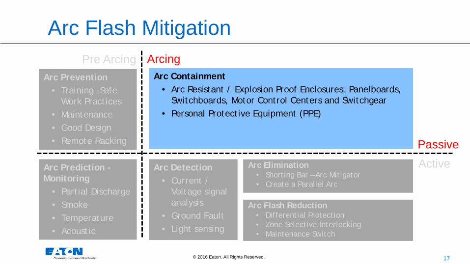
Arc Flash Mitigation
Arc Prediction - Monitoring
• Partial Discharge • Smoke • Temperature • Acoustic
Arc Prevention • Training -Safe
Work Practices • Maintenance • Good Design • Remote Racking
Arc Detection
• Current / Voltage signal analysis
• Ground Fault • Light sensing
Arc Containment • Arc Resistant / Explosion Proof Enclosures: Panelboards,
Switchboards, Motor Control Centers and Switchgear • Personal Protective Equipment (PPE)
Arc Elimination • Shorting Bar – Arc Mitigator • Create a Parallel Arc
Active Passive
Pre Arcing Arcing
Arc Flash Reduction • Differential Protection • Zone Selective Interlocking • Maintenance Switch
Original Source: IEC SC17B

4 © 2016 Eaton. All Rights Reserved..
Arc Flash Mitigation
Arc Prevention • Training -Safe
Work Practices • Maintenance • Good Design • Remote Racking
Arc Detection
• Current / Voltage signal analysis
• Ground Fault • Light sensing
Arc Containment • Arc Resistant / Explosion Proof Enclosures: Panelboards,
Switchboards, Motor Control Centers and Switchgear • Personal Protective Equipment (PPE)
Arc Elimination • Shorting Bar – Arc Mitigator • Create a Parallel Arc
Active Passive
Pre Arcing Arcing
Arc Flash Reduction • Differential Protection • Zone Selective Interlocking • Maintenance Switch
Arc Prediction - Monitoring
• Partial Discharge • Smoke • Temperature • Acoustic

5 © 2016 Eaton. All Rights Reserved..
Arc Prevention
• De-energize equipment if at all possible
• Label Equipment & Train Personnel
• Minimize Risk with Good Safety Practices
• Move People Further Away
• Closing and tightening door latches or door bolts before operating a switch
• Design the Hazard Out (Safety by Design)
• Reduce Available Fault Current
• Faster Clearing Times

6 © 2016 Eaton. All Rights Reserved..
Training Minimize Risks with Good Safety Practices
Bad – Exposed Back of Neck Good – All of Body Protected Toward the Arc Flash Area
7 © 2016 Eaton. All Rights Reserved..
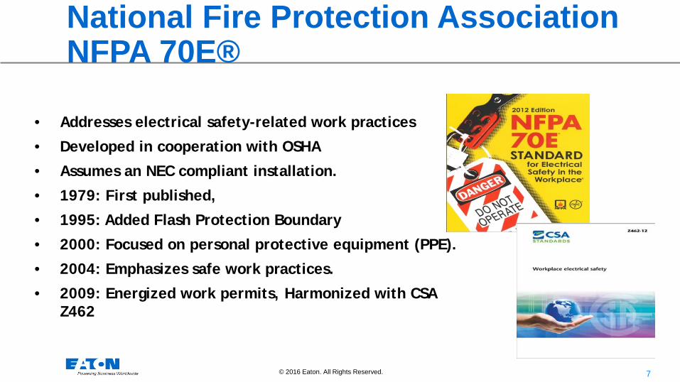
• Addresses electrical safety-related work practices
• Developed in cooperation with OSHA
• Assumes an NEC compliant installation.
• 1979: First published,
• 1995: Added Flash Protection Boundary
• 2000: Focused on personal protective equipment (PPE).
• 2004: Emphasizes safe work practices.
• 2009: Energized work permits, Harmonized with CSA Z462
National Fire Protection Association NFPA 70E®
8 © 2016 Eaton. All Rights Reserved..
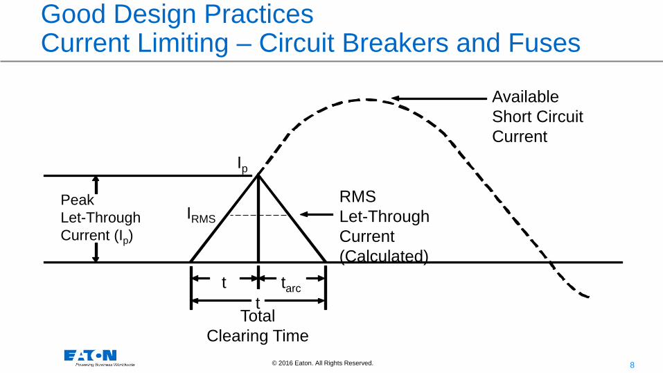
Good Design Practices Current Limiting – Circuit Breakers and Fuses
Peak Let-Through Current (Ip)
IRMS
RMS Let-Through Current (Calculated)
Total Clearing Time
t t tarc
Ip
Available Short Circuit Current

9 © 2016 Eaton. All Rights Reserved..
VS.
Good Design Remote Racking and Robots

10 © 2016 Eaton. All Rights Reserved..
Racking MCCB Breakers
Dead-front Cover
Dead-front Handles
Racking Window

11 © 2016 Eaton. All Rights Reserved..
Arc Flash Mitigation
Arc Prediction - Monitoring
• Partial Discharge • Smoke • Temperature • Acoustic
Arc Prevention • Training -Safe
Work Practices • Maintenance • Good Design • Remote Racking
Arc Detection
• Current / Voltage signal analysis
• Ground Fault • Light sensing
Arc Containment • Arc Resistant / Explosion Proof Enclosures: Panelboards,
Switchboards, Motor Control Centers and Switchgear • Personal Protective Equipment (PPE)
Arc Elimination • Shorting Bar – Arc Mitigator • Create a Parallel Arc
Active Passive
Pre Arcing Arcing
Arc Flash Reduction • Differential Protection • Zone Selective Interlocking • Maintenance Switch
12 © 2016 Eaton. All Rights Reserved..
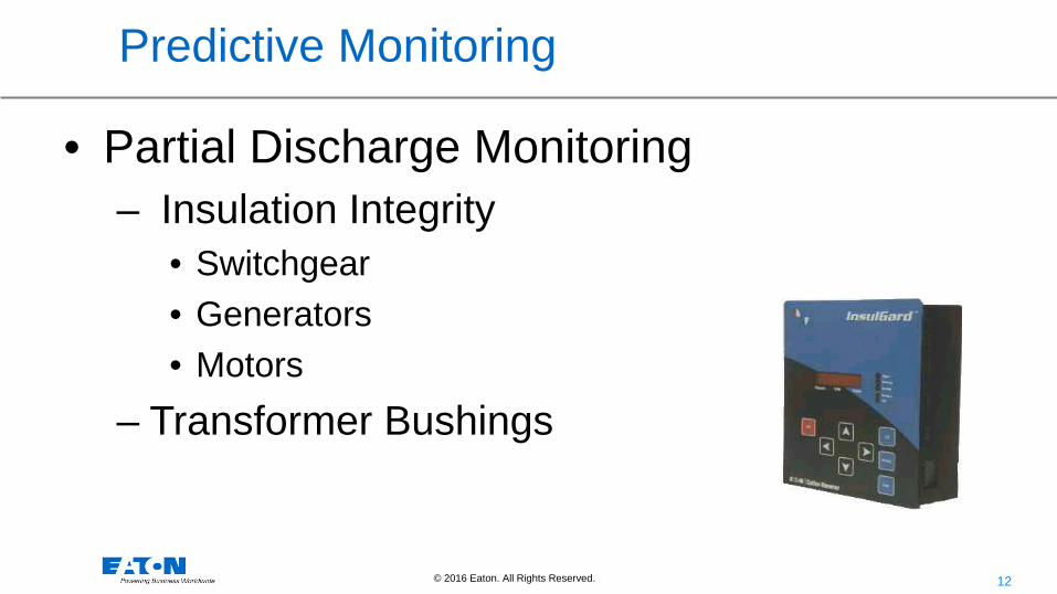
Predictive Monitoring
• Partial Discharge Monitoring – Insulation Integrity
• Switchgear • Generators • Motors
– Transformer Bushings
13 © 2016 Eaton. All Rights Reserved..
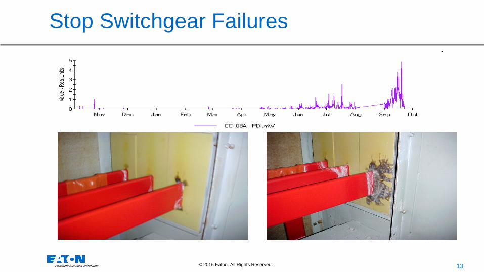
Stop Switchgear Failures

14 © 2016 Eaton. All Rights Reserved..
• Traditional Infrared Thermograph survey using IR Windows or Viewports
• Visual Inspections • Scheduled regularly for intervals
between shutdown maintenance • “snapshot” of temperature at the time
of the viewing. – Thermographer wears appropriate PPE
while in the flash boundary
Thermography – View Ports

15 © 2016 Eaton. All Rights Reserved..
• IR scan identified 149.4oF hot spot temperature
• Temperature above the IEEE 1458 Standard of 130oF.
• Removed from service and returned for further analysis
Thermal Scan - Example

16 © 2016 Eaton. All Rights Reserved..
• New technology that detects acoustic signature of micro-arcing of loose connections before they become dangerous.
Acoustic Arc Detection
17 © 2016 Eaton. All Rights Reserved..
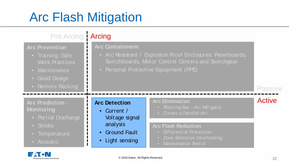
Arc Flash Mitigation
Arc Prevention • Training -Safe
Work Practices • Maintenance • Good Design • Remote Racking
Arc Detection
• Current / Voltage signal analysis
• Ground Fault • Light sensing
Arc Containment • Arc Resistant / Explosion Proof Enclosures: Panelboards,
Switchboards, Motor Control Centers and Switchgear • Personal Protective Equipment (PPE)
Arc Elimination • Shorting Bar – Arc Mitigator • Create a Parallel Arc
Active Passive
Pre Arcing Arcing
Arc Flash Reduction • Differential Protection • Zone Selective Interlocking • Maintenance Switch
Arc Prediction - Monitoring
• Partial Discharge • Smoke • Temperature • Acoustic
18 © 2016 Eaton. All Rights Reserved..
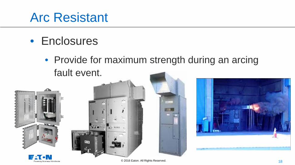
Arc Resistant
• Enclosures • Provide for maximum strength during an arcing
fault event.

19 © 2016 Eaton. All Rights Reserved..
Shuster
ARC Resistant - Testing
• Test is successful if: • No indicators are burned
• Doors do not open
• No projectiles come from equipment
• No holes are burned in the enclosure

20 © 2016 Eaton. All Rights Reserved..
65kA / 508V Arc initiated in breaker compartment Plenum Design
Arc projected out of plenum
No arc flash out of the front of the gear
Arc Safety– Arc Resistant Gear

21 © 2016 Eaton. All Rights Reserved..
PPE Clothing Hazard
RiskCategory
Clothing Description(Number of clothing
layers given inparenthesis)
TotalWeightoz./yd2
Minimum Arc ThermalPerformance Exposure
Value (ATPV)* orBreakopen ThresholdEnergy (Ebt)* Rating of
PPE cal/cm2
0 Untreated Cotton (1) 4.7 - 7 1.2
1 FR Shirt and FR Pants (1) 4.5 – 8 4
2Cotton Underware plus FRShirt and FR Pants 9 – 12 8
3Cotton Underwear plus FRShirt and FR Pants plus FRCoverall (3)
16 – 20 25
4Cotton Underwear plus FRShirt and FR Pants plusDouble Layer SwitchingCoat and Pants (4)
24 -40 40
Extracted from NFPA 70E-2004 Based upon maximum energy for a 2nd degree burn (1.2 cal/cm2)
Category 4 PPE
22 © 2016 Eaton. All Rights Reserved..
Arc Flash Mitigation
Arc Prevention • Training -Safe
Work Practices • Maintenance • Good Design • Remote Racking
Arc Detection
• Current / Voltage signal analysis
• Ground Fault • Light sensing
Arc Containment • Arc Resistant / Explosion Proof Enclosures: Panelboards,
Switchboards, Motor Control Centers and Switchgear • Personal Protective Equipment (PPE)
Arc Elimination • Shorting Bar – Arc Mitigator • Create a Parallel Arc
Active Passive
Pre Arcing Arcing
Arc Flash Reduction • Differential Protection • Zone Selective Interlocking • Maintenance Switch
Arc Prediction - Monitoring
• Partial Discharge • Smoke • Temperature • Acoustic
23 © 2016 Eaton. All Rights Reserved..
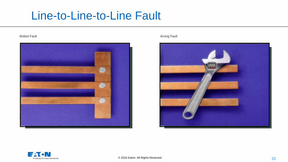
Line-to-Line-to-Line Fault Bolted Fault Arcing Fault
Systems must be designed However, the majority of faults for worst case conditions. will be arcing type.
24 © 2016 Eaton. All Rights Reserved..
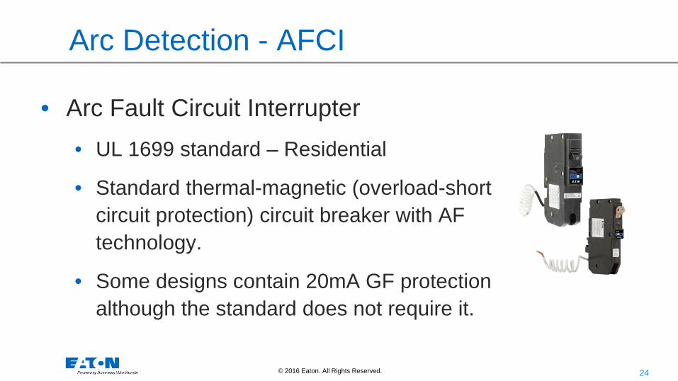
Arc Detection - AFCI
• Arc Fault Circuit Interrupter • UL 1699 standard – Residential
• Standard thermal-magnetic (overload-short circuit protection) circuit breaker with AF technology.
• Some designs contain 20mA GF protection although the standard does not require it.

25 © 2016 Eaton. All Rights Reserved..
Arc Detection - AFCI
Parallel arc fault AFCI
120V ac
Z
Series arc
Z
Load
Sputtering parallel arc waveform
Cable impedance

26 © 2016 Eaton. All Rights Reserved..
Arc Detection - AFCI
Standard overcurrent protection does not detect if: • Parallel Arc Faults are sputtering – will not trip on overload because
there is not enough RMS heating current.
• Parallel Arc Faults that are limited due to wiring impedances – Below the breaker’s instantaneous value.
• Algorithms for Parallel arc fault protection looking at the slope of the rise of the fault current.
• Series Arc Faults that look like load current – Ok arcs (light switch, bi-metal on a skillet or coffee pot)
• Complex Algorithms for series arc faults to detect the signature of good vs. bad arcs.
27 © 2016 Eaton. All Rights Reserved..
Arc Detection - Ground Fault Sensing
• Different levels of protection: • Machinery Equipment Protection
• 30mA Sensitivity = Equipment Protection
• Personnel Protection • NEC Code says less than 6mA sensitivity required to protect people
• IEC standard says less than 30mA sensitivity should be used.
• High Resistance Grounding • Reduces the level of current in arcing faults to ground

28 © 2016 Eaton. All Rights Reserved..
Arc Flash Light Detection Relays
• Speed, no intentional delays (2ms operate time – 52ms Trip Time)
• Sensitive, adjustable phase and ground fault current set-points from sensitive to above load
• Selectivity, trip only affected feeder(s)
• Secure, dual-sensing option (current and light) prevents false trips
• Full self-supervision

29 © 2016 Eaton. All Rights Reserved..
EAFR-07 – Arc light glass fiber sensor
EAFR-06 – Arc light plastic fiber sensor
Arc Light Detection - Sensors

30 © 2016 Eaton. All Rights Reserved..
700’
- Wired connections provides simple installation and allows full factory testing even with shipping splits
- Current signaling based information (2mA, 20mA)
- Maximum 3 sensors in line (up to 700feet)
- Snap-in cable connector for quick installation - Shielded cable connection - Three styles of different light intensity (8000,
25000, or 50000 Lux) - 180 degrees of visibility.
Arc Light Detection - Point Light Sensor
31 © 2016 Eaton. All Rights Reserved..
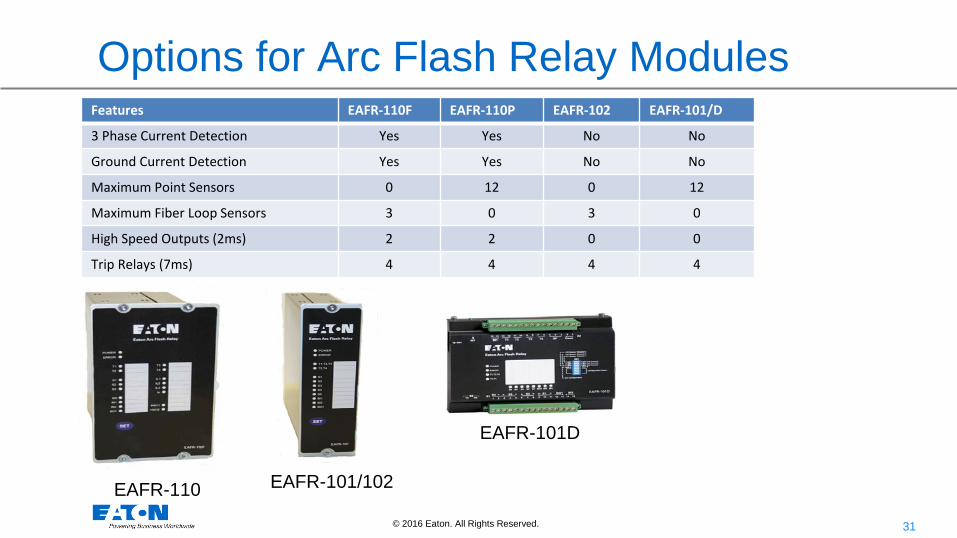
Options for Arc Flash Relay Modules Features EAFR-110F EAFR-110P EAFR-102 EAFR-101/D
3 Phase Current Detection Yes Yes No No
Ground Current Detection Yes Yes No No
Maximum Point Sensors 0 12 0 12
Maximum Fiber Loop Sensors 3 0 3 0
High Speed Outputs (2ms) 2 2 0 0
Trip Relays (7ms) 4 4 4 4
EAFR-110 EAFR-101/102
EAFR-101D

32 © 2016 Eaton. All Rights Reserved..
Arc Detection – Light / Current
• Detect (sputtering) low power phase to ground arc faults
• Optimal sensor sensitivity for quick detection before fault escalates.
• Current pickup setting for high resistance sputtering fault current condition on phase or ground.
Trip Signal sent out
33 © 2016 Eaton. All Rights Reserved..
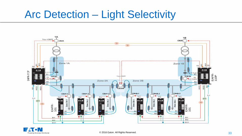
Arc Detection – Light Selectivity
EAFR
-11
0P
EAFR
-10
1
EAFR
-10
1

34 © 2016 Eaton. All Rights Reserved..
Sensor Locations
• Point Sensors
• Arrows Point to the Fiber Loop
35 © 2016 Eaton. All Rights Reserved..
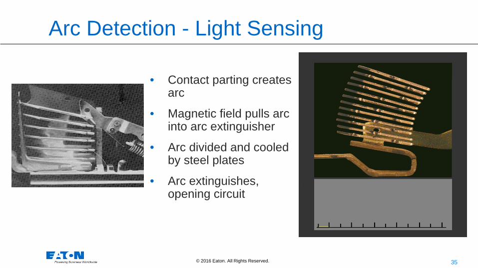
• Contact parting creates arc
• Magnetic field pulls arc into arc extinguisher
• Arc divided and cooled by steel plates
• Arc extinguishes, opening circuit
Arc Detection - Light Sensing

36 © 2016 Eaton. All Rights Reserved..
Arc Detection - Light Sensing • Low Voltage Circuit Breakers
create arc flash light when they interrupt.
• Do not want to trip the upstream circuit breaker on the light produced by the circuit breaker that is closest to the fault and is interrupting to clear the fault.
• There are light sensing relays with restrain signals to prevent nuisance trip on circuit breaker arc flash.

37 © 2016 Eaton. All Rights Reserved..
Fault/Arc Clearing Timing
Fault Current / Arcing Event Starts
Light Sensor Tripping a Circuit Breaker
Light Detected and initiate a Shunt Trip coil
Breaker contacts part
Fault Clears
13ms 35ms 2 to 7ms ~52ms

38 © 2016 Eaton. All Rights Reserved..
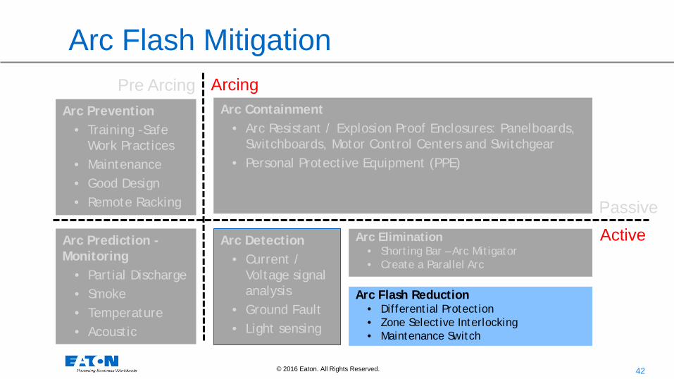
Arc Flash Mitigation
Arc Prevention • Training -Safe
Work Practices • Maintenance • Good Design • Remote Racking
Arc Detection
• Current / Voltage signal analysis
• Ground Fault • Light sensing
Arc Containment • Arc Resistant / Explosion Proof Enclosures: Panelboards,
Switchboards, Motor Control Centers and Switchgear • Personal Protective Equipment (PPE)
Arc Elimination • Shorting Bar – Arc Mitigator • Create a Parallel Arc
Active Passive
Pre Arcing Arcing
Arc Flash Reduction • Differential Protection • Zone Selective Interlocking • Maintenance Switch
Arc Prediction - Monitoring
• Partial Discharge • Smoke • Temperature • Acoustic
39 © 2016 Eaton. All Rights Reserved..
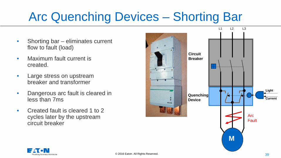
Arc Quenching Devices – Shorting Bar
• Shorting bar – eliminates current flow to fault (load)
• Maximum fault current is created.
• Large stress on upstream breaker and transformer
• Dangerous arc fault is cleared in less than 7ms
• Created fault is cleared 1 to 2 cycles later by the upstream circuit breaker
M
I>
L1 L2 L3
Quenching Device
Circuit Breaker
Light
Current
Arc Fault
40 © 2016 Eaton. All Rights Reserved..
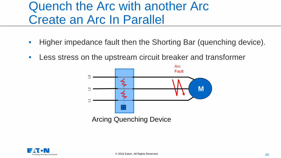
Quench the Arc with another Arc Create an Arc In Parallel • Higher impedance fault then the Shorting Bar (quenching device).
• Less stress on the upstream circuit breaker and transformer
M L1
L2
L
3
Arc Fault
Arcing Quenching Device

41 © 2016 Eaton. All Rights Reserved..
Fault/Arc Clearing Timing
Fault Current / Arcing Event Starts
Quenching Device Enabled Short Circuit eliminated Created Fault Clears
32ms 4 to 7ms
Light Sensor Tripping a Circuit Breaker
Light Detected and initiate a Shunt Trip coil
Breaker contacts part
Fault Clears
13ms 35ms 2 to 7ms
~5ms
~52ms
42 © 2016 Eaton. All Rights Reserved..
Arc Flash Mitigation
Arc Prevention • Training -Safe
Work Practices • Maintenance • Good Design • Remote Racking
Arc Detection
• Current / Voltage signal analysis
• Ground Fault • Light sensing
Arc Containment • Arc Resistant / Explosion Proof Enclosures: Panelboards,
Switchboards, Motor Control Centers and Switchgear • Personal Protective Equipment (PPE)
Arc Elimination • Shorting Bar – Arc Mitigator • Create a Parallel Arc
Active Passive
Pre Arcing Arcing
Arc Flash Reduction • Differential Protection • Zone Selective Interlocking • Maintenance Switch
Arc Prediction - Monitoring
• Partial Discharge • Smoke • Temperature • Acoustic
43 © 2016 Eaton. All Rights Reserved..
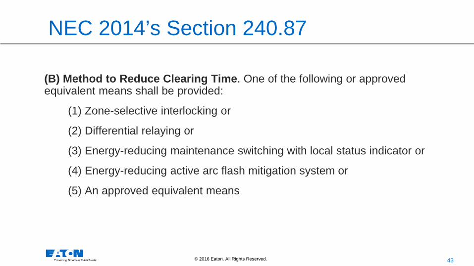
NEC 2014’s Section 240.87
(B) Method to Reduce Clearing Time. One of the following or approved equivalent means shall be provided:
(1) Zone-selective interlocking or
(2) Differential relaying or
(3) Energy-reducing maintenance switching with local status indicator or
(4) Energy-reducing active arc flash mitigation system or
(5) An approved equivalent means

44 © 2016 Eaton. All Rights Reserved..
(1) Zone Selective Interlocking
Important Clearing Time Information
45 © 2016 Eaton. All Rights Reserved..
ZSI
• zone selective interlock (ZSI): A system feature designed to reduce thermal and mechanical stress on electrical distribution equipment during short-circuit or ground-fault events. ZSI permits the nearest upstream circuit breaker to a short-circuit or ground-fault to clear the fault without intentional delay, while maintaining system coordination, see NEMA PB 2.2. Per NEMA AB3-2013
46 © 2016 Eaton. All Rights Reserved..
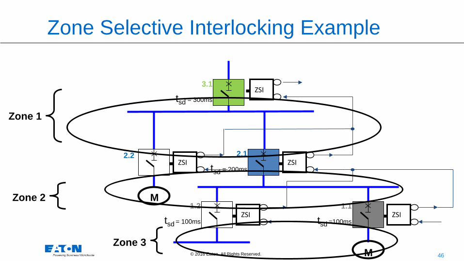
Zone Selective Interlocking Example
Zone 1
Zone 2
Zone 3
ZSI
ZSI ZSI
ZSI
ZSI
2.2 2.1
tsd = 200ms
1.1
tsd =100ms
1.2
tsd = 100ms
3.1
tsd = 300ms
M
M

47 © 2016 Eaton. All Rights Reserved..
ZSI
ZSI ZSI
ZSI
ZSI
2.2 2.1
tsd = 200ms
1.1
tsd =100ms
1.2
tsd = 100ms
3.1
tsd = 300ms
M
10
1
0.1
0.01
3.1 2.1 1.1
3
Zone Selective Interlocking
Fault Current
Trip Time
Zone 1
Zone 2
Zone 3 M
3

48 © 2016 Eaton. All Rights Reserved..
ZSI
ZSI ZSI
ZSI
ZSI
2.2 2.1
tsd = 200ms
1.1
tsd =100ms
1.2
tsd = 100ms
3.1
tsd = 300ms
M
10
1
0.1
0.01
3
Zone Selective Interlocking
Fault Current
Trip Time
Zone 1
Zone 2
Zone 3 M
3 Zone Trip
3.1 2.1 1.1

49 © 2016 Eaton. All Rights Reserved..
ZSI
ZSI ZSI
ZSI
ZSI
2.2 2.1
tsd = 200ms
1.1
tsd =100ms
1.2
tsd = 100ms
3.1
tsd = 300ms
M
10
1
0.1
0.01
2
Zone Selective Interlocking
Fault Current
Trip Time
Zone 1
Zone 2
Zone 3 M
2
3.1 2.1 1.1

50 © 2016 Eaton. All Rights Reserved..
ZSI
ZSI ZSI
ZSI
ZSI
2.2 2.1
tsd = 200ms
1.1
tsd =100ms
1.2
tsd = 100ms
3.1
tsd = 300ms
M
10
1
0.1
0.01
2
Zone Selective Interlocking
Fault Current
Trip Time
Zone 1
Zone 2
Zone 3 M
2
Zone Trip
3.1 2.1 1.1

51 © 2016 Eaton. All Rights Reserved..
1
ZSI
ZSI ZSI
ZSI
ZSI
2.2 2.1
tsd = 200ms
1.1
tsd =100ms
1.2
tsd = 100ms
3.1
tsd = 300ms
M
10
1
0.1
0.01
1
Zone Selective Interlocking
Fault Current
Trip Time
Zone 1
Zone 2
Zone 3 M
3.1 2.1 1.1

52 © 2016 Eaton. All Rights Reserved..
1
ZSI
ZSI ZSI
ZSI
ZSI
Zone 1
Zone 2
2.2 2.1
tsd = 200ms
1.1
tsd =100ms
1.2
tsd = 100ms
3.1
tsd = 300ms
M
10
1
0.1
0.01
1 Fault Current
Trip Time
Zone 3 M
Zone Selective Interlocking
Zone Trip
3.1 2.1 1.1
53 © 2016 Eaton. All Rights Reserved..
ZSI – Design Considerations
• Number of devices
• Auxiliary Power – requirement
• Length of each run
• Compatibility with other protective devices – MV
54 © 2016 Eaton. All Rights Reserved..
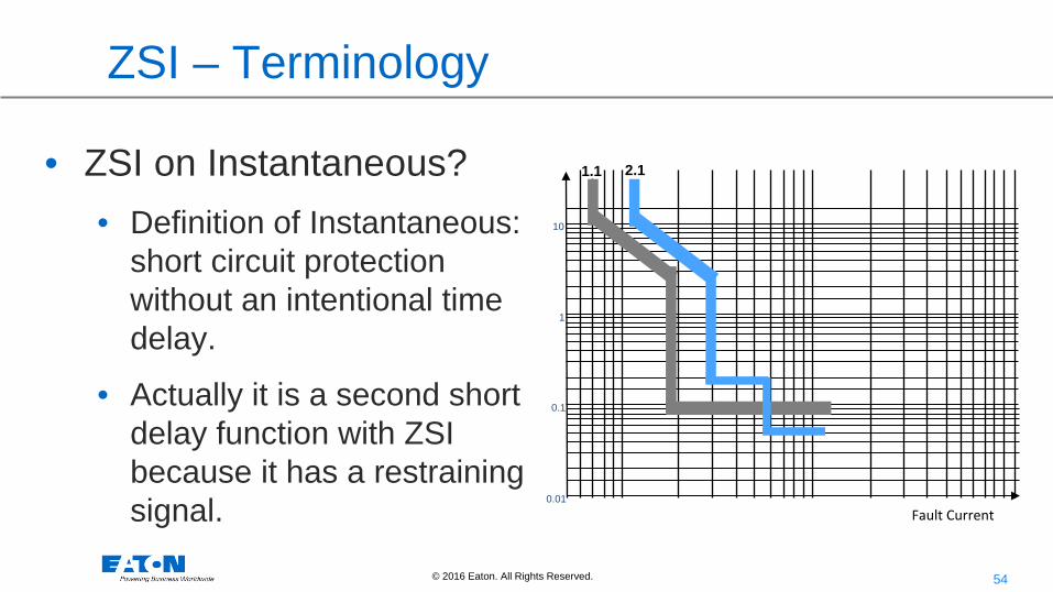
ZSI – Terminology
• ZSI on Instantaneous? • Definition of Instantaneous:
short circuit protection without an intentional time delay.
• Actually it is a second short delay function with ZSI because it has a restraining signal.
10
1
0.1
0.01
Fault Current
2.1 1.1

55 © 2016 Eaton. All Rights Reserved..
Fault/Arc Clearing Timing
Fault Current / Arcing Event Starts
Quenching Device Enabled Short Circuit eliminated Created Fault Clears
32ms 4 to 7ms
Light Sensor Tripping a Circuit Breaker
Light Detected and initiate a Shunt Trip coil
Breaker contacts part
Fault Clears
13ms 35ms 2 to 7ms
~5ms
~52ms
Zone Interlock Trip
ETU powers up
Breaker contacts part
Fault Clears
16ms 13ms 37ms 4 to 6ms ~70ms
Zone Out Signal
21ms Trip Coil Engaged
56 © 2016 Eaton. All Rights Reserved..
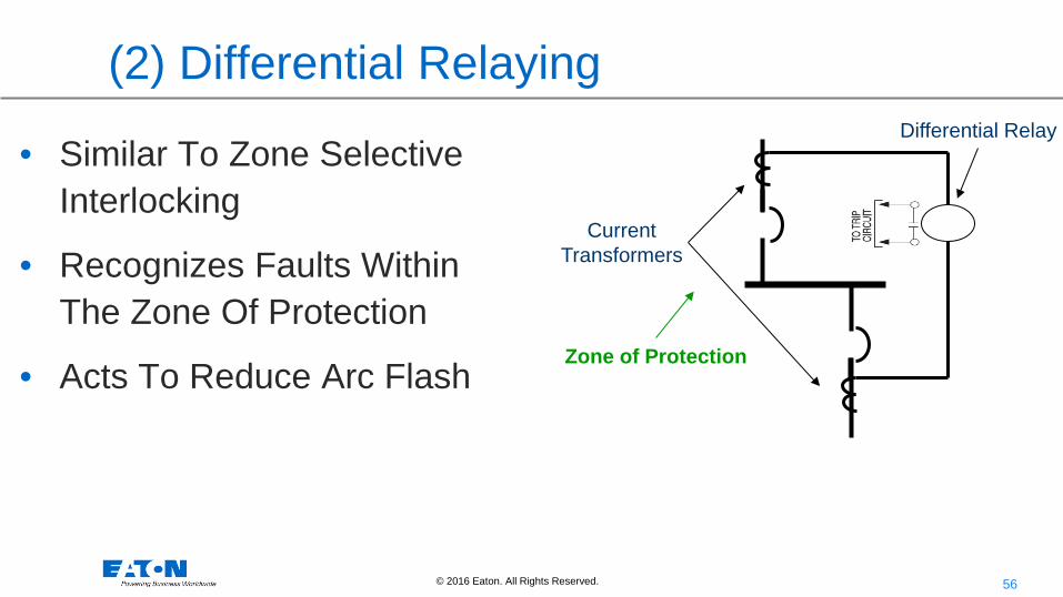
(2) Differential Relaying
• Similar To Zone Selective Interlocking
• Recognizes Faults Within The Zone Of Protection
• Acts To Reduce Arc Flash
Current Transformers
Differential Relay
Zone of Protection

57 © 2016 Eaton. All Rights Reserved..
Differential Relaying
• Recognizes Faults Within The Zone Of Protection
• Current into and out of the zone must equal.
• If current is not balanced it is going into Acts To Reduce Arc Flash
Current Transformers
Differential Relay
Zone of Protection

58 © 2016 Eaton. All Rights Reserved..
Fault/Arc Clearing Timing
Fault Current / Arcing Event Starts
Quenching Device Enabled Short Circuit eliminated Created Fault Clears
32ms 4 to 7ms
Light Sensor Tripping a Circuit Breaker
Light Detected and initiate a Shunt Trip coil
Breaker contacts part
Fault Clears
13ms 35ms 2 to 7ms
~5ms
~52ms
Zone Interlock Trip
ETU powers up
Breaker contacts part
Fault Clears
16ms 13ms 37ms 4 to 6ms ~70ms
Zone Out Signal
21ms Trip Coil Engaged
Software Instantaneous Trip ETU powers up
Breaker contacts part
Fault Clears
16ms 13ms 25ms 4 to 6ms
~58ms Trip Coil Engaged

59 © 2016 Eaton. All Rights Reserved..
(3) Energy-reducing maintenance switching with local status indicator
Lockout
Tag out
Switch
Indicating Light

60 © 2016 Eaton. All Rights Reserved..
• ARMS uses a separate bypass path that is strictly
analog, bypassing all issues such as microprocessor boot up time, A/D conversion rate or code execution time saving a couple of milliseconds (and therefore calories) over something that "just" uses the instantaneous trip.
• Blue LED “Maintenance Mode” lit indicates that it is engaged.
5 Position Arc Flash Reduction Setting:
From R5 (10x trip rating) …. To R1 (2.5x trip rating) Reduction
• Remote Indication:
• Power Relay Module Maintenance Mode Contact
• Remote Enable: via communications
• Lock-out/Tag-out
Arc Flash Reduction Maintenance Switch
61 © 2016 Eaton. All Rights Reserved..
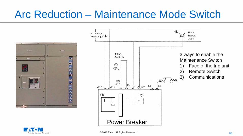
Arc Reduction – Maintenance Mode Switch
3 ways to enable the Maintenance Switch 1) Face of the trip unit 2) Remote Switch 3) Communications
Power Breaker
62 © 2016 Eaton. All Rights Reserved..
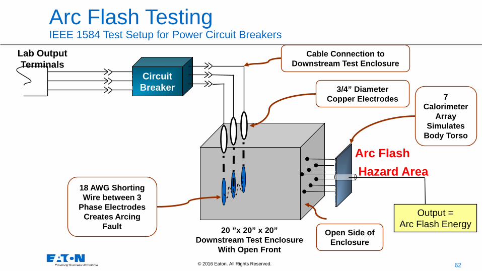
Circuit Breaker
Output = Arc Flash Energy
Lab Output Terminals
Cable Connection to Downstream Test Enclosure
18 AWG Shorting Wire between 3
Phase Electrodes Creates Arcing
Fault
7 Calorimeter
Array Simulates
Body Torso
Open Side of Enclosure
20 ”x 20” x 20” Downstream Test Enclosure
With Open Front
3/4” Diameter Copper Electrodes
Arc Flash Hazard Area
Arc Flash Testing IEEE 1584 Test Setup for Power Circuit Breakers
63 © 2016 Eaton. All Rights Reserved..
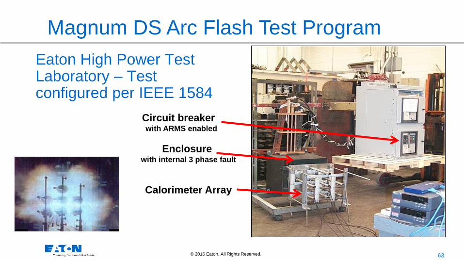
Eaton High Power Test Laboratory – Test configured per IEEE 1584
Magnum DS Arc Flash Test Program
Calorimeter Array
Enclosure with internal 3 phase fault
Circuit breaker with ARMS enabled
64 © 2016 Eaton. All Rights Reserved..
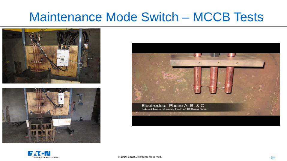
Maintenance Mode Switch – MCCB Tests

65 © 2016 Eaton. All Rights Reserved..
Arc Flash Reduction Maintenance Switch (ARMS)
• ARMS uses a separate bypass path that is strictly analog, bypassing all issues such as microprocessor boot up time, A/D conversion rate or code execution time saving a couple of milliseconds (and therefore calories) over something that "just" uses the instantaneous trip.
66 © 2016 Eaton. All Rights Reserved..
Upon completion of the maintenance, the lock is removed, the switch is manually opened, and all previous trip unit settings are again re-activated, without need for recalibration.
Arc Flash Reduction Maintenance Switch (ARMS)

67 © 2016 Eaton. All Rights Reserved..
Maintenance Mode Now Available for Molded Case Circuit Breakers
MCCB Breaker with Maintenance Mode Equipped Trip Unit
•Two instantaneous Maintenance Mode Settings of 2.5 and 4x In
•Five Instantaneous Normal Mode Settings of 6, 7, 8, 10 and 12 x In

68 © 2016 Eaton. All Rights Reserved..
Maintenance Mode Trip Curves
0.01
0.1
1
10
100
1000
1 10 100
Time (
s)
Current (pu)
ARMS 2.5X
6X
2.5X
120ms

69 © 2016 Eaton. All Rights Reserved..
Fault/Arc Clearing Timing
Fault Current / Arcing Event Starts
Quenching Device Enabled Short Circuit eliminated Created Fault Clears
32ms 4 to 7ms
Light Sensor Tripping a Circuit Breaker
Light Detected and initiate a Shunt Trip coil
Breaker contacts part
Fault Clears
13ms 35ms 2 to 7ms
~5ms
~52ms
Zone Interlock Trip
ETU powers up
Breaker contacts part
Fault Clears
16ms 13ms 37ms 4 to 6ms ~70ms
Zone Out Signal
21ms Trip Coil Engaged
Software Instantaneous Trip ETU powers up
Breaker contacts part
Fault Clears
16ms 13ms 25ms 4 to 6ms
~58ms Trip Coil Engaged
Maintenance Mode Switch (ARMS) Trip Analog powers up
Trip Coil Engaged
Breaker contacts part
Fault Clears
16ms 13ms 4 to 6ms ~33ms
70 © 2016 Eaton. All Rights Reserved..
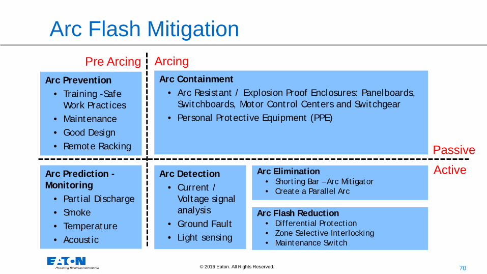
Arc Flash Mitigation
Arc Prediction - Monitoring
• Partial Discharge • Smoke • Temperature • Acoustic
Arc Prevention • Training -Safe
Work Practices • Maintenance • Good Design • Remote Racking
Arc Detection
• Current / Voltage signal analysis
• Ground Fault • Light sensing
Arc Containment • Arc Resistant / Explosion Proof Enclosures: Panelboards,
Switchboards, Motor Control Centers and Switchgear • Personal Protective Equipment (PPE)
Arc Elimination • Shorting Bar – Arc Mitigator • Create a Parallel Arc
Active Passive
Pre Arcing Arcing
Arc Flash Reduction • Differential Protection • Zone Selective Interlocking • Maintenance Switch