arbor · press the bar opening on the universal clamp onto the bar. provisionally tighten the...
TRANSCRIPT

ARBOR™ External Fixation System
SURGICAL TECHNIQUE GUIDE GLOBUSMEDICAL.COM/TRAUMA | Life moves us

Our mission is to deliver cutting-edge technology, research, and innovative solutions to promote healing in
patients with musculoskeletal disorders.
The Surgical Technique shown is for illustrative purposes only. The technique(s) actually employed in each case always depends on the medical judgment of the surgeon exercised before and during surgery as to the best mode of treatment for each patient. Additionally, as instruments may occasionally be updated, the instruments depicted in this Surgical Technique may not be exactly the same as the instruments currently available. Please consult with your sales representative or contact Globus directly for more information.

System Overview . . . . . . . . . . . . . . . . . . . . . . . . . . . . . . . . . . . . . . . . . . . . . . . . . . . . . . . . . . . . . . . . . .4
Implant Overview . . . . . . . . . . . . . . . . . . . . . . . . . . . . . . . . . . . . . . . . . . . . . . . . . . . . . . . . . . . . . . . . .6
Surgical Technique
Universal Clamps
1. Insert the Drill Guide . . . . . . . . . . . . . . . . . . . . . . . . . . . . . . . . . . . . . . . . . . . . . . . . . . . . . . . . . . . 8
Drill Measuring . . . . . . . . . . . . . . . . . . . . . . . . . . . . . . . . . . . . . . . . . . . . . . . . . . . . . . . . . . . . . . . .9
2. Pin Insertion . . . . . . . . . . . . . . . . . . . . . . . . . . . . . . . . . . . . . . . . . . . . . . . . . . . . . . . . . . . . . . . . . 10
Attaching the Silicone Ratcheting Handle to the Multi-Tool . . . . . . . . . . . . . . . . . . . . . . . 10
3. Clamp Attachment . . . . . . . . . . . . . . . . . . . . . . . . . . . . . . . . . . . . . . . . . . . . . . . . . . . . . . . . . . . 12
4. Bar Attachment . . . . . . . . . . . . . . . . . . . . . . . . . . . . . . . . . . . . . . . . . . . . . . . . . . . . . . . . . . . . . . 13
5. Final Tightening . . . . . . . . . . . . . . . . . . . . . . . . . . . . . . . . . . . . . . . . . . . . . . . . . . . . . . . . . . . . . . 14
Final Construct . . . . . . . . . . . . . . . . . . . . . . . . . . . . . . . . . . . . . . . . . . . . . . . . . . . . . . . . . . . . . . . . . 15
Multi-Pin Clamps
1. Multi-Pin Clamp Assembly . . . . . . . . . . . . . . . . . . . . . . . . . . . . . . . . . . . . . . . . . . . . . . . . . . . . 16
2. Using the Multi-Pin Clamp . . . . . . . . . . . . . . . . . . . . . . . . . . . . . . . . . . . . . . . . . . . . . . . . . . . . 16
3. Drilling and Pin Placement . . . . . . . . . . . . . . . . . . . . . . . . . . . . . . . . . . . . . . . . . . . . . . . . . . . . 17
4. Connecting Attachment Posts . . . . . . . . . . . . . . . . . . . . . . . . . . . . . . . . . . . . . . . . . . . . . . . . . 18
5. Final Tightening . . . . . . . . . . . . . . . . . . . . . . . . . . . . . . . . . . . . . . . . . . . . . . . . . . . . . . . . . . . . . . 19
Final Construct . . . . . . . . . . . . . . . . . . . . . . . . . . . . . . . . . . . . . . . . . . . . . . . . . . . . . . . . . . . . . . . . 20
Removal . . . . . . . . . . . . . . . . . . . . . . . . . . . . . . . . . . . . . . . . . . . . . . . . . . . . . . . . . . . . . . . . . . . . . . . 20
Final Construct Frames . . . . . . . . . . . . . . . . . . . . . . . . . . . . . . . . . . . . . . . . . . . . . . . . . . . . . . . . . . . 21
Instrument Overview . . . . . . . . . . . . . . . . . . . . . . . . . . . . . . . . . . . . . . . . . . . . . . . . . . . . . . . . . . . . .28
ARBOR™ External Fixation System Implant Set . . . . . . . . . . . . . . . . . . . . . . . . . . . . . . . . . . . . 30
ARBOR™ External Fixation System Instrument Set . . . . . . . . . . . . . . . . . . . . . . . . . . . . . . . . . .32
Important Information. . . . . . . . . . . . . . . . . . . . . . . . . . . . . . . . . . . . . . . . . . . . . . . . . . . . . . . . . . . .34
SURGICAL TECHNIQUE GUIDE
ARBOR™ External Fixation System

4 | ARBOR™ External Fixation System
ARBOR™
External Fixation System
The ARBOR™ External Fixation System provides a streamlined set of external fixation devices including clamps, pins, and bars. This system offers a one-clamp design for every procedure regardless of pin size. Innovative instruments allow surgeons to quickly create the frame of their choice.
Universal Clamp• Allows bar-to-bar connection or pin-to-bar connection• One clamp for all 3-6mm pins
Schanz Pins• Self-drilling, blunt-tip, and transfix• Depth graduations for optimal pin placement• AO quick-connection
Carbon Fiber Bars• Chamfered edges allow easy assembly into clamp• 11mm diameter and 100–650mm lengths

LIFE MOVES US | 5
M U L T I - T O O L
SPANNING WRENCH
AO CONNECTION FOR PIN OR DRILL ATTACHMENT
IN-LINE WRENCH
6 | ARBOR™ External Fixation System
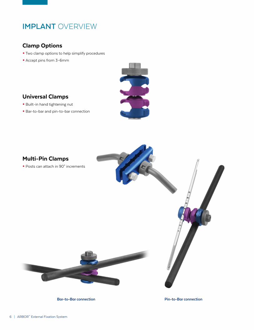
Clamp Options• Two clamp options to help simplify procedures
• Accept pins from 3–6mm
Multi-Pin Clamps• Posts can attach in 90° increments
Universal Clamps• Built-in hand tightening nut
• Bar-to-bar and pin-to-bar connection
IMPLANT OVERVIEW
Bar-to-Bar connection Pin-to-Bar connection
LIFE MOVES US | 7
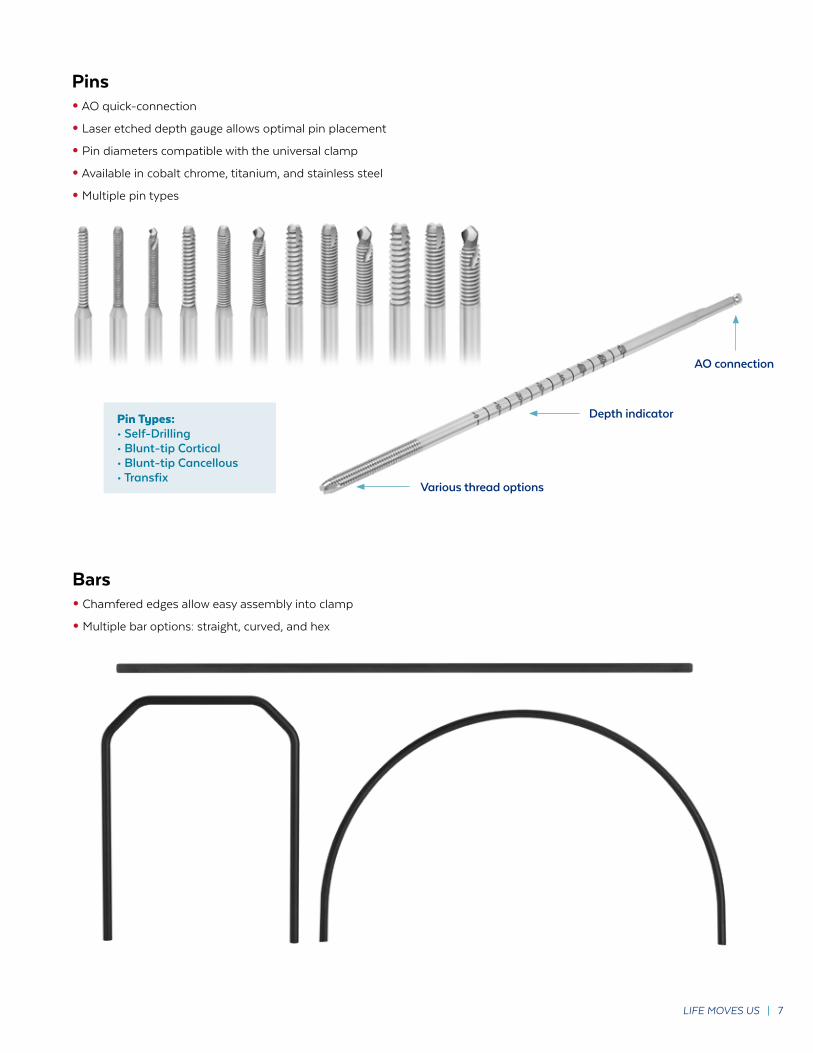
Pins• AO quick-connection
• Laser etched depth gauge allows optimal pin placement
• Pin diameters compatible with the universal clamp
• Available in cobalt chrome, titanium, and stainless steel
• Multiple pin types
Bars• Chamfered edges allow easy assembly into clamp
• Multiple bar options: straight, curved, and hex
Pin Types:• Self-Drilling• Blunt-tip Cortical• Blunt-tip Cancellous• Transfix
Various thread options
AO connection
Depth indicator
8 | ARBOR™ External Fixation System
SURGICAL TECHNIQUE
ARBOR™ External Fixation System
Refer to the package insert for important information on the intended use/indications, device description, contraindications, precautions, warnings, and potential risks associated with this system.
Preoperative Plannning
Assess the fracture using preoperative radiographs. Make the appropriate incision through the skin above or below the fracture.
UNIVERSAL CLAMPS
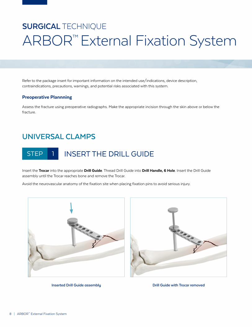
STEP 1 INSERT THE DRILL GUIDE
Insert the Trocar into the appropriate Drill Guide. Thread Drill Guide into Drill Handle, 6 Hole. Insert the Drill Guide assembly until the Trocar reaches bone and remove the Trocar.
Avoid the neurovascular anatomy of the fixation site when placing fixation pins to avoid serious injury.
Inserted Drill Guide assembly Drill Guide with Trocar removed

LIFE MOVES US | 9
SURGICAL TECHNIQUE
ARBOR™ External Fixation System
Optional: Pre-Drilling
For self-tapping pins, select the appropriate Drill Bit and attach to selected drill. Insert the Drill Bit through the Drill Guide. Pre-drill the first cortex, slowing the drill speed once in cancellous bone. Once the second cortex has been penetrated stop drilling and remove the Drill Bit.
Pre-drilling through the Drill Guide
DRILL MEASURING
Drill guides are available in various lengths to accommodate patient anatomy. Each drill guide is marked with an offset value, which indicates depth when paired with a graduated pin or drill.
For 65mm drill guide, depth is read directly from the pin or drill.
For 95mm drill guide, subtract 30mm from the measured value to calculate depth.
For the 115mm drill guide, subtract 50mm from the measured value to calculate depth.
10 | ARBOR™ External Fixation System
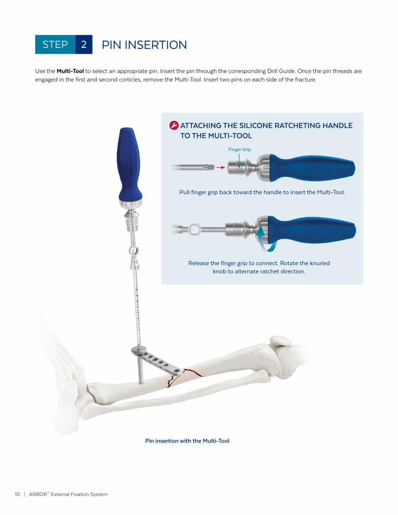
STEP 2 PIN INSERTION
Use the Multi-Tool to select an appropriate pin. Insert the pin through the corresponding Drill Guide. Once the pin threads are engaged in the first and second corticies, remove the Multi-Tool. Insert two pins on each side of the fracture.
Pin insertion with the Multi-Tool
ATTACHING THE SILICONE RATCHETING HANDLE TO THE MULTI-TOOL
Pull finger grip back toward the handle to insert the Multi-Tool.
Release the finger grip to connect. Rotate the knurled knob to alternate ratchet direction.
Finger Grip

LIFE MOVES US | 11
Optional: Self-Drilling
For self-drilling, attach the appropriate self-drilling pin to the drill. Insert the pin through the corresponding Drill Guide. Drill until the pin engages the second cortex. Detach and remove the drill from the pin.
Self-drilling pin insertion

12 | ARBOR™ External Fixation System
STEP 3 CLAMP ATTACHMENT
Ensure the tightening nut is loosened completely. Press the pin opening on the Universal Clamp onto the pin.
Repeat this process for all clamps.
Placing the Universal Clamps

LIFE MOVES US | 13
STEP 4 BAR ATTACHMENT
Select the appropriate carbon fiber bar. Press the bar opening on the Universal Clamp onto the bar. Provisionally tighten the construct by tightening the nut on each universal clamp to ensure the pins and bars do not disengage. Repeat this process for all bars.
Placing the carbon fiber bar
Provisionally tighten the nut manually Provisionally tighten the nut using the Multi-Tool

14 | ARBOR™ External Fixation System
STEP 5 FINAL TIGHTENING
Select the Multi-Tool or Ratcheting Combination Wrench for final tightening. Tighten clockwise until construct is secure while maintaining fracture reduction. Ensure that all clamps are securely tightened to the pins and bar.
Final tightening
If using the Ratcheting Combination Wrench, use the “LOCK” side to securely tighten and the “UNLOCK” side to loosen.

LIFE MOVES US | 15
FINAL CONSTRUCT
Final Construct with Universal Clamps

16 | ARBOR™ External Fixation System
MULTI-PIN CLAMPS
STEP 1 MULTI-PIN CLAMP ASSEMBLY
Assemble the attachment posts to the Multi-Pin Clamp by aligning the posts with the side of the Multi-Pin Clamp. Rotate the tightening nut on the post clockwise until secure. Tighten posts using the Combination Wrench.
STEP 2 USING THE MULTI-PIN CLAMP
Thread the appropriate Drill Guide into the Drill Guide Handle. The distance between drill guides should match the selected Multi-Pin Clamp.
Aligning post to Multi-Pin Clamp Rotating the post nut
LIFE MOVES US | 17
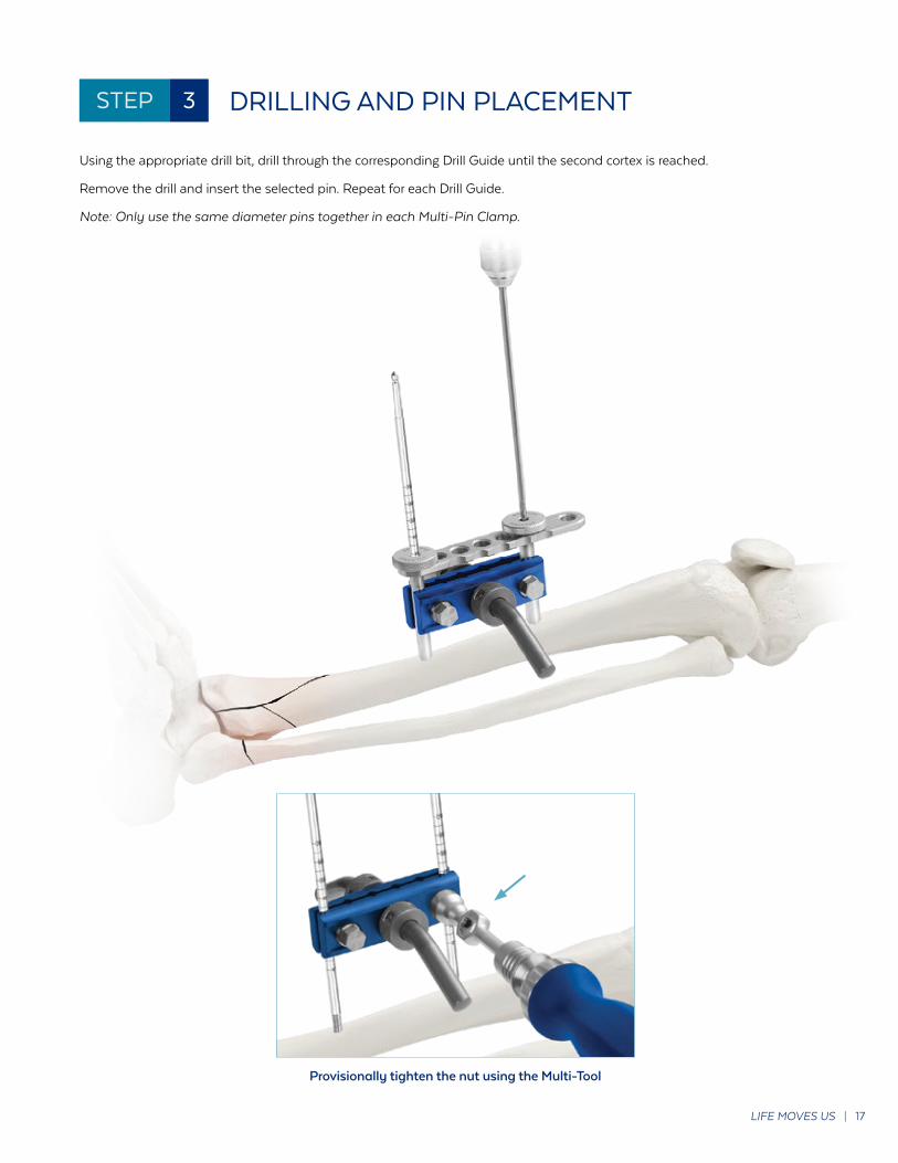
STEP 3 DRILLING AND PIN PLACEMENT
Using the appropriate drill bit, drill through the corresponding Drill Guide until the second cortex is reached.
Remove the drill and insert the selected pin. Repeat for each Drill Guide.
Note: Only use the same diameter pins together in each Multi-Pin Clamp.
Provisionally tighten the nut using the Multi-Tool
18 | ARBOR™ External Fixation System
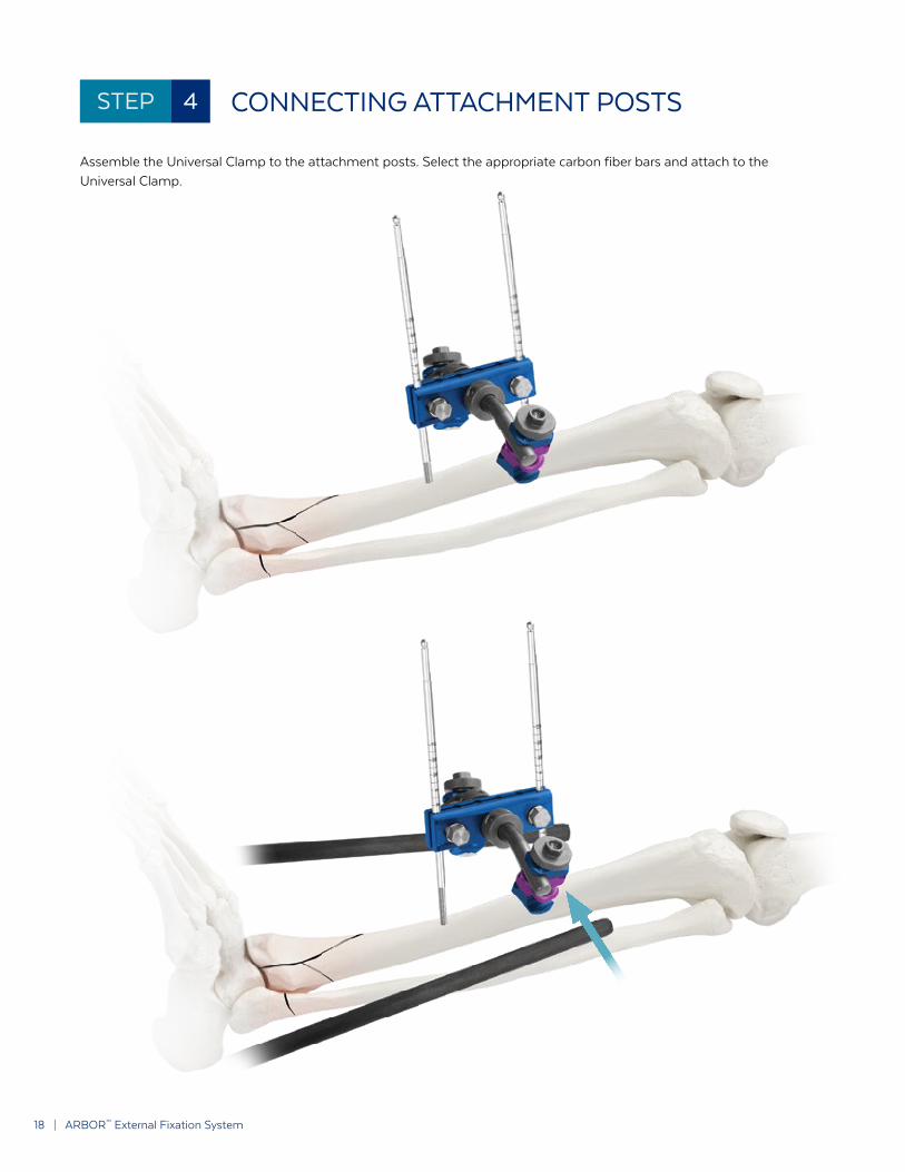
STEP 4 CONNECTING ATTACHMENT POSTS
Assemble the Universal Clamp to the attachment posts. Select the appropriate carbon fiber bars and attach to the Universal Clamp.

LIFE MOVES US | 19
STEP 5 FINAL TIGHTENING
Once the bars are in the correct position, tighten the Universal Clamp using the Multi-Tool, Combination Wrench, or Ratcheting Combination Wrench. Secure the Multi-Pin Clamp by using the selected wrench to tighten the hex nuts on the side. Ensure that all clamps are securely tightened to the pins and bars.

20 | ARBOR™ External Fixation System
FINAL CONSTRUCT
REMOVAL
For removal, loosen all the clamps of the construct. Remove the bars from the clamps, then remove the clamps from the pins. Attach the desired handle to each pin and rotate counterclockwise to remove the pins.
Final Construct with Multi-Pin and Universal Clamps

LIFE MOVES US | 21
Final ARBOR™ constructs are determined by patient anatomy, fracture pattern, and surgeon discretion.
Examples of commonly used frames are shown on the following pages.
SPANNING FRAME - TIBIA

22 | ARBOR™ External Fixation System
DELTA FRAME

LIFE MOVES US | 23
PELVIC FRAME - CURVED BARS
PELVIC FRAME - SEGMENTED BARS

24 | ARBOR™ External Fixation System
SPANNING FRAME - HUMERUS

LIFE MOVES US | 25
SPANNING FRAME - KNEE
26 | ARBOR™ External Fixation System
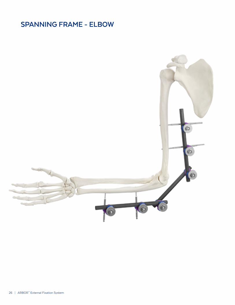
SPANNING FRAME - ELBOW

LIFE MOVES US | 27
SPANNING FRAME - DISTAL RADIUS
28 | ARBOR™ External Fixation System
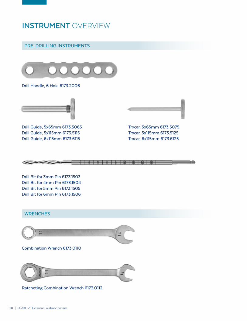
INSTRUMENT OVERVIEW
Drill Handle, 6 Hole 6173.2006
Combination Wrench 6173.0110
Ratcheting Combination Wrench 6173.0112
Drill Guide, 5x65mm 6173.5065Drill Guide, 5x115mm 6173.5115Drill Guide, 6x115mm 6173.6115
Drill Bit for 3mm Pin 6173.1503Drill Bit for 4mm Pin 6173.1504Drill Bit for 5mm Pin 6173.1505Drill Bit for 6mm Pin 6173.1506
Trocar, 5x65mm 6173.5075Trocar, 5x115mm 6173.5125Trocar, 6x115mm 6173.6125
PRE-DRILLING INSTRUMENTS
WRENCHES

LIFE MOVES US | 29
T-Handle 3 Jaw Chuck 6173.9000
Silicone Ratcheting Handle 630.407
Multi-Tool 6173.0111 Silicone Ratcheting Handle 630.407(Fully Assembled)
Multi-Tool 6173.0111
Snap Distractor, Left Hand 6173.9110 Snap Distractor, Right Hand 6173.9111
WRENCHES (CONT’D)
DISTRACTORS

30 | INDEPENDENCE MIS™ 30 | ARBOR™ External Fixation System
ARBOR™ EXTERNAL FIXATION SYSTEM IMPLANT SET 9173.0000
Clamps QTY
1173.0001 Universal Clamp, 4 holes 16
1173.0006 Multi-Pin Clamp, 6 holes 4
1173.0030 30° Clamp Post 8
Carbon Fiber Bars QTY
5173.1110 Carbon Fiber Bar, 11x100mm 1
5173.1115 Carbon Fiber Bar, 11x150mm 1
5173.1120 Carbon Fiber Bar, 11x200mm 1
5173.1125 Carbon Fiber Bar, 11x250mm 1
5173.1130 Carbon Fiber Bar, 11x300mm 1
5173.1135 Carbon Fiber Bar, 11x350mm 1
5173.1140 Carbon Fiber Bar, 11x400mm 1
5173.1145 Carbon Fiber Bar, 11x450mm 1
5173.1150 Carbon Fiber Bar, 11x500mm 1
5173.1155 Carbon Fiber Bar, 11x550mm 1
5173.1160 Carbon Fiber Bar, 11x600mm 1
5173.1165 Carbon Fiber Bar, 11x650mm 1
End Caps
6173.1006 Protective End Caps for Pins
Pins
X173.2200 Schanz Pin, Blunt-Tip, 3x90mm, 20mm Cortical Thread 2
X173.2303 Schanz Pin, Blunt-Tip, 4x150mm, 30mm Cortical Thread 2
X173.5404 Schanz Pin, Blunt-Tip, 5x200mm, 40mm Cortical Thread 8
X173.8405 Schanz Pin, Blunt-Tip, 6x250mm, 40mm Cortical Thread 4
X173.3200 Schanz Pin, Self-Drilling, 3x90mm, 20mm Cortical Thread 2
X173.3303 Schanz Pin, Self-Drilling, 4x150mm, 30mm Cortical Thread 2
X173.6404 Schanz Pin, Self-Drilling, 5x200mm, 40mm Cortical Thread 8
X173.9405 Schanz Pin, Self-Drilling, 6x250mm, 40mm Cortical Thread 4
X173.0407 Transfix Pin, 5/6x350mm, 40mm Thread 2
X173.0408 Transfix Pin, 5/6x400mm, 40mm Thread 2

LIFE MOVES US | 31LIFE MOVES US | 31

32 | INDEPENDENCE MIS™ 32 | ARBOR™ External Fixation System
ARBOR™ EXTERNAL FIXATION SYSTEM INSTRUMENT SET 9173.0001
Instrument QTY
1 6173.2006 Drill Guide Handle, 6 Hole 3
2 6173.5065 Drill Guide, 5x65mm 3
3 6173.5115 Drill Guide, 5x115mm 3
4 6173.6115 Drill Guide, 6x115mm 3
5 6173.5075 Trocar, 5x65mm 3
6 6173.5125 Trocar, 5x115mm 3
7 6173.6125 Trocar, 6x115mm 3
8 6173.1503 Drill Bit for 3mm pin 2
9 6173.1504 Drill Bit for 4mm pin 2
10 6173.1505 Drill Bit for 5mm pin 2
11 6173.1506 Drill Bit for 6mm pin 2
12 6173.9000 T-handle 3 Jaw Chuck 1
13 6173.0111 Multi-Tool 1
14 630.4070 Silicone Ratcheting Handle 1
15 6173.0112 Ratcheting Wrench, 11mm 1
16 6173.0110 Combination Wrench, 11mm 1
17 6173.9111 Snap Distractor, Left Hand 1
18 6173.9110 Snap Distractor, Right Hand 1
GC.112 Graphic Case

LIFE MOVES US | 33LIFE MOVES US | 33
12
109
118
4 3 2
5
1
67
17
18
13 14
16
15

34 | ARBOR™ External Fixation System
DESCRIPTIONThe ARBOR™ External Fixation System is comprised of Schanz pins, external fixation clamps, and bars. The pins and bars are available in various sizes, and the fixation clamps are available in several designs all capable of use with any size pins and bars.
ARBOR™ pins and clamps are manufactured from titanium alloy, cobalt chromium molybdenum alloy, or stainless steel, as specified in ASTM F136, F138, F139, F899, F1058, F1295, F1472, F1537, and F2229. ARBOR™ pins are also available with hydroxyapatite (HA) coating as specified in ASTM F1185. ARBOR™ bars are manufactured from carbon fiber reinforced epoxy.
INDICATIONSThe ARBOR™ External Fixation System is indicated for use in construction of an external fixation frame for the treatment of pediatric and adult fractures and/or reconstruction of long bones, small bones (including metacarpal and metatarsal), and the pelvis.
The ARBOR™ External Fixation System is intended for:• Stabilization of open or closed fractures with soft tissue injuries;• Polytrauma;• Vertically stable pelvic fractures or as a treatment adjunct for vertically unstable
pelvic fractures;• Arthrodesis and osteotomies with soft tissue problems;• Revision procedures where other devices have been unsuccessful including
failures of total joints;• Neutralization of fractures stabilized with limited internal fixation;• Non-unions/septic non-unions;• Intraoperative reduction/stabilization tool to assist with indirect reduction;• Correction of deformity; and• Unilateral rectilinear bone segment transport or leg lengthening.
WARNINGSThe correct implant selection is extremely important. Failure to use the appropriate implant for the fracture condition may accelerate clinical failure. Failure to use the proper component to maintain adequate blood supply and provide rigid fixation may result in loosening, bending, cracking or fracture of the implant and/or bone. The correct implant size for a given patient can be determined by evaluating the patient’s height, weight, functional demands and anatomy. Every implant must be used in the correct anatomic location, consistent with accepted standards of internal fixation.
Implanting metals and alloys in the human body subjects them to an aggressive chemical environment of salts, acids, and proteins, which can cause corrosion. Dissimilar metals in contact with each other can accelerate the corrosion process due to galvanic corrosion effects. Thus, mixing of implant components from different manufacturers is not recommended, for metallurgical, mechanical and function reasons.
PRECAUTIONSThe implantation of external fixation devices should be performed only by experienced surgeons with specific training in the use of this system because this is a technically demanding procedure presenting a risk of serious injury to the patient. Preoperative planning and patient anatomy should be considered when selecting implant size.
External fixation pins must never be reused. An explanted implant must never be reused. Even though the device appears undamaged, it may have small defects and internal stress patterns which could lead to breakage. For reprocessing instructions for non-implanted, reusable devices (e.g. clamps, bars), refer to the REPROCESSING section below.
Surgeons must respect the neurovascular anatomy of the fixation site. Care must be taken to avoid these structures when placing fixation pins, to avoid serious injury.
MRI SAFETY INFORMATION
Non-clinical testing demonstrated that the ARBOR™ External Fixation System is MR Conditional. A patient with this device can be scanned safely in an MR system immediately after placement under the following conditions:• Static magnetic field of 1.5-Tesla and 3-Tesla, only• Maximum spatial gradient magnetic field of 3000 Gauss/cm or less• Maximum MR system reported, whole body averaged specific absorption rate
(SAR) of <2-W/kg in the Normal Operating Mode of operation for the MR system• The entire device must be visible outside the MRI bore• Under the scan conditions defined, the ARBOR™ External Fixation System is
expected to produce a maximum temperature rise of 2°C after 15-minutes of continuous scanning when the device is visibly out of the coil.
Artifact InformationIn non-clinical testing, the image artifact caused by the ARBOR™ External Fixation System extends approximately 43mm
from this implant when imaged using a gradient echo pulse sequence and a 3.0 Tesla MRI system.
CONTRAINDICATIONSUse of these implants is contraindicated in patients with the following conditions:• Patients in whom no screws can be inserted due to a bone or soft tissue disease.
ADVERSE EFFECTSIn many instances, adverse results may be clinically related rather than device related. The following are the most frequent adverse effects involving the use of external fracture fixation devices:• Delayed union or non-union of the fracture site.• These devices can break when subjected to the increased loading associated
with delayed unions and/or non-unions. External fixation devices are load-sharing devices which are intended to hold fracture bone surface in a position to facilitate healing. If healing is delayed or does not occur, the appliance may eventually break due to metal fatigue. Loads on the device produced by load bearing and the patient’s activity level dictate the longevity of the device.
• Conditions attributable to non-union, osteoporosis, osteomalicia, diabetes, inhibited revascularization and poor bone formation can cause loosening, bending, cracking, fracture of the device or premature loss of rigid fixation with the bone.
• Improper alignment can cause a malunion of the bone and bending, cracking or even breakage of the device.
• Increased fibrous tissue response around the fracture site due to unstable comminuted fractures.
• Early or late infection, deep or superficial.• Edema.• Septic arthritis.• Pin loosening.• Pin breakage or movement at the fracture site caused by use of too few pins or
pins that are too small.• Excessive motion at the fracture site caused by failure to tighten the component
parts of the device.• Bone separation induced by rapid drilling of the bony cortex.• Chronic drainage of bone screw or wire sites after device removal.• Inadequate fracture reduction because of failure to pin the bone segments
correctly.• Thrombosis.• Ankle stiffness.• Deep venous thrombosis.• Avascular necrosis.• Shortening of the effected bone/fracture site.• Nerve damage due to surgical trauma.• Metal sensitivity, or allergic reaction to a foreign body.• Decrease in bone density, pain, discomfort, or abnormal sensations due to the
presence of the device, and vascular changes.
CAUTIONSPre-operative• Pins are single patient use only.• Pins that came in contact with body fluids should never be reused.• Ensure that all components needed for surgery are available in the surgical
suite.• Inspection is recommended prior to surgery to determine if implants have been
damaged during storage.• While rare, intraoperative fracture or breakage of instruments can occur.
Instruments which have experienced excessive use or excessive force are susceptible to fracture. Instruments should be examined for wear or damage prior to surgery.
Intraoperative• Discard all damaged or mishandled implants.• Contouring or bending of an implant should be avoided where possible,
because it may reduce its fatigue strength and can cause failure under load.• Implants are available in different versions, varying for example in length,
diameter, material and number of drilled holes. Select the required version carefully.
• During the course of the operation, repeatedly check to ensure that the connection between the implant and the instrument, or between the instruments, is secure.
• Implants which consist of several components must only be used in the prescribed combination (refer to the ARBOR™ Surgical Technique Guide).
• After the procedure, check the proper positioning of all implants.• Do not use components from this system in conjunction with components
from any other manufacturer unless otherwise specified (refer to the ARBOR™ Surgical Technique Guide).
Postoperative• These implants are neither intended to carry the full load of the patient acutely,
nor intended to carry a significant portion of the load for extended periods of time. For this reason, postoperative instructions and warnings to patients are extremely important.
• The injured limb should be kept elevated.• Depending on the construct and surgeon preference, full weight bearing
walking may be started immediately.• In the event of a delay in bone consolidation or if such consolidation does
not take place, complications may occur, for example fracture or loosening of the implant or instability of the implant system. Regular postoperative examinations (e.g. x-ray checks) are advisable.
• Patients who cannot follow the recommendations of the physician because of a mental or neuromuscular disorder must have additional postoperative follow-up.
• Advise the patient of daily cleaning of pin-skin interface.
IMPORTANT INFORMATION ON ARBOR™ EXTERNAL FIXATION SYSTEM
LIFE MOVES US | 35
• Implant removal should be followed by adequate postoperative management to avoid fracture or refracture of the bone.
Informing the PatientThe implant affects the patient’s ability to carry loads and her/his mobility and general living circumstances. The surgeon must counsel each patient individually on correct behavior and activity after the implantation.
Metallic implants can loosen, fracture, corrode, migrate, cause pain, or stress shield bone even after a fracture has healed, particularly in young, active patients. While the surgeon must make the final decision on implant removal, we recommend that whenever possible and practical for the individual patient, fixation devices should be removed once their service as an aid to healing is accomplished. Implant removal should be followed by adequate postoperative management to avoid refracture.
PACKAGINGThese implants and instruments may be supplied pre-packaged and sterile, using gamma irradiation. The integrity of the sterile packaging should be checked to ensure that sterility of the contents is not compromised. Packaging should be carefully checked for completeness and all components should be carefully checked to ensure that there is no damage prior to use. Damaged packages or products should not be used, and should be returned to Globus Medical. During surgery, after the correct size has been determined, remove the products from the packaging using aseptic technique.
These implants and instruments may also be provided nonsterile and are steam sterilized prior to use, as described in the STERILIZATION section below. Following use or exposure to soil, instruments and instrument trays and cases must be cleaned, as described in the CLEANING section below.
HANDLINGAll instruments and implants should be treated with care. Improper use or handling may lead to damage and/or possible malfunction. Instruments should be checked to ensure that they are in working order prior to surgery.
Pins and sterile-packed instruments are single use devices and should not be cleaned. Re-cleaning of single use implants might lead to mechanical failure and/or material degradation. Discard any pins or single use instruments that may have been accidently contaminated.
Sterile-packed pins and instruments that have become nonsterile but have not been used or contaminated may be resterilized using the instructions for nonsterile devices in the STERILIZATION section below.
CLEANINGAll instruments that can be disassembled must be disassembled for cleaning. All handles must be detached. Instruments may be reassembled following sterilization. The instruments should be cleaned using neutral cleaners before sterilization and introduction into a sterile surgical field or (if applicable) return of the product to Globus Medical.
Cleaning and disinfecting of instruments can be performed with aldehyde-free solvents at higher temperatures. Cleaning and decontamination must include the use of neutral cleaners followed by a deionized water rinse. Note: certain cleaning solutions such as those containing formalin, glutaraldehyde, bleach and/or other alkaline cleaners may damage some devices, particularly instruments; these solutions should not be used.
The following cleaning methods should be observed when cleaning instruments after use or exposure to soil, and prior to sterilization:1. Immediately following use, ensure that the instruments are wiped down to
remove all visible soil and kept from drying by submerging or covering with a wet towel.
2. Disassemble all instruments that can be disassembled.3. Rinse the instruments under running tap water to remove all visible soil. Flush
the lumens a minimum of 3 times,until the lumens flush clean.4. Prepare Enzol® (or a similar enzymatic detergent) per manufacturer’s
recommendations.5. Immerse the instruments in the detergent and allow them to soak for a
minimum of 2 minutes.6. Use a soft bristled brush to thoroughly clean the instruments. Use a pipe
cleaner for any lumens. Pay close attention to hard to reach areas.7. Using a sterile syringe, draw up the enzymatic detergent solution. Flush any
lumens and hard to reach areas until no soil is seen exiting the area.8. Remove the instruments from the detergent and rinse them in running warm
tap water.9. Prepare Enzol® (or a similar enzymatic detergent) per manufacturer’s
recommendations in an ultrasonic cleaner.10. Completely immerse the instruments in the ultrasonic cleaner and ensure
detergent is in lumens by flushing the lumens. Sonicate for a minimum of 3 minutes.
11. Remove the instruments from the detergent and rinse them in running deionized water or reverse osmosis water for a minimum of 2 minutes.
12. Dry instruments using a clean soft cloth and filtered pressurized air.13. Visually inspect each instrument for visible soil. If visible soil is present, then
repeat cleaning process starting with Step 3.
REPROCESSING• PRODUCTS LABELED FOR SINGLE-USE MUST NOT BE REUSED.
• Repeated reprocessing has minimal effect on reusable devices. End of life is normally determined by wear and damage due to use.
• Remove gross soiling by submerging the device into cold water (<40°C) immediately after use. Do not use fixating detergent or hot water as this can cause the fixation of residua which may influence the result of the reprocessing process. Remove surface contamination with paper tissue.
• Follow hospital protocols when handling contaminated and bio-hazardous materials. Devices should be cleaned within 30 minutes after use to minimize the potential of staining, damage and drying.
• Do not attempt to resterilize. Globus Medical, Inc. will not accept devices for reprocessing that have been reprocessed or sterilized by other facilities.
• Pack the devices in a biohazard bag and ship to Globus Medical, Inc. for reprocessing.
CONTACT INFORMATIONGlobus Medical may be contacted at 1-866-GLOBUS1 (456-2871). A surgical technique manual may be obtained by contacting Globus Medical.
STERILIZATIONThese implants and instruments may be available sterile or nonsterile. HA-coated implants are only available sterile.
Sterile implants and instruments are sterilized by gamma radiation, validated to ensure a Sterility Assurance Level (SAL) of 10-6. Sterile products are packaged in a heat sealed, container/pouch. The expiration date is provided on the package label. These products are considered sterile unless the packaging has been opened or damaged.
Nonsterile implants and instruments have been validated to ensure an SAL of 10-6. The use of an FDA-cleared wrap is recommended, per the Association for the Advancement of Medical Instrumentation (AAMI) ST79, Comprehensive Guide to Steam Sterilization and Sterility Assurance in Health Care Facilities. It is the end user’s responsibility to use only sterilizers and accessories (such as sterilization wraps, sterilization pouches, chemical indicators, biological indicators, and sterilization cassettes) that have been cleared by the FDA for the selected sterilization cycle specifications (time and temperature). Sterile implants meet pyrogen limit specifications.
When using a rigid sterilization container, the following must be taken into consideration for proper sterilization of Globus devices and loaded graphic cases:• Recommended sterilization parameters are listed in the table below.• Only FDA-cleared rigid sterilization containers for use with pre-vacuum steam
sterilization may be used.• When selecting a rigid sterilization container, it must have a minimum filter area
of 176 in2 total, or a minimum of four (4) 7.5in diameter filters.• No more than one (1) loaded graphic case or its contents can be placed directly
into a rigid sterilization container.• Stand-alone modules/racks or single devices must be placed, without stacking,
in a container basket to ensure optimal ventilation.• The rigid sterilization container manufacturer’s instructions for use are to be
followed; if questions arise, contact the manufacturer of the specific container for guidance.
• Refer to AAMI ST79 for additional information concerning the use of rigid sterilization containers.
For implants and instruments provided NONSTERILE, sterilization is recommended (wrapped or containerized) as follows:
Method Cycle Type Temperature Exposure Time Drying Time
Steam Pre-vacuum 132°C (270°F) 4 Minutes 30 Minutes
Do not stack trays during sterilization. These parameters are validated to sterilize only this device. If other products are added to the sterilizer, the recommended parameters are not valid and new cycle parameters must be established by the user. The sterilizer must be properly installed, maintained, and calibrated. Ongoing testing must be performed to confirm inactivation of all forms of viable microorganisms.
CAUTION: Federal (U.S.A.) Law restricts this Device to Sale by or on the Order of a Physician.
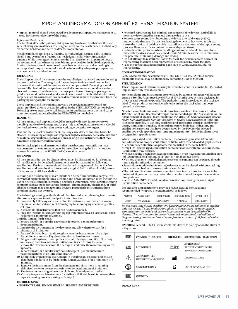
CATALOGUE NUMBER STERILIZED BY IRRADIATION
LOT NUMBERAUTHORISED REPRESENTATIVE IN THE EUROPEAN COMMUNITY
ATTENTION, SEE INSTRUCTIONS FOR USE
MANUFACTURER
SINGLE USE ONLY USE BY (YYYY-MM-DD)
QUANTITY
DI202A REV A
IMPORTANT INFORMATION ON ARBOR™ EXTERNAL FIXATION SYSTEM

Globus MedicalValley Forge Business Center2560 General Armistead AvenueAudubon, PA 19403www.globusmedical.com
Customer Service:Phone 1-866-GLOBUS1 (or 1-866-456-2871) Fax 1-866-GLOBUS3 (or 1-866-456-2873)
GMTGD19403.18 Rev A
P: RMS – UK Limited 28 Trinity Road, Nailsea, Somerset, BS48 4NU England
©2018 Globus Medical. All rights reserved. Patent www.globusmedical.com/patents. Life moves us is a registered trademark of Globus Medical. Please refer to package insert for description, indications, contraindications, warnings, precautions and other important information.