aquistar pt2x - rs · pdf fileaquistar® pt2x pressure/temperature ... appendix b: field...
TRANSCRIPT

8902 122nd Avenue NEKirkland, WA 98033 USA 425-822-4434FAX 425-822-8384 / [email protected]
INW
AquiStar® PT2XPressure/Temperature Smart Sensor and Datalogger
©1997 - 2011 by Instrumentation Northwest, Inc. All rights reserved. Instrumentation Northwest and INW are trademarks registered with the U.S. Patent & Trademark Offi ce. Doc# 9B0730r11 05/2011 / PN 6D275-NI
INSTRUCTION MANUAL
1
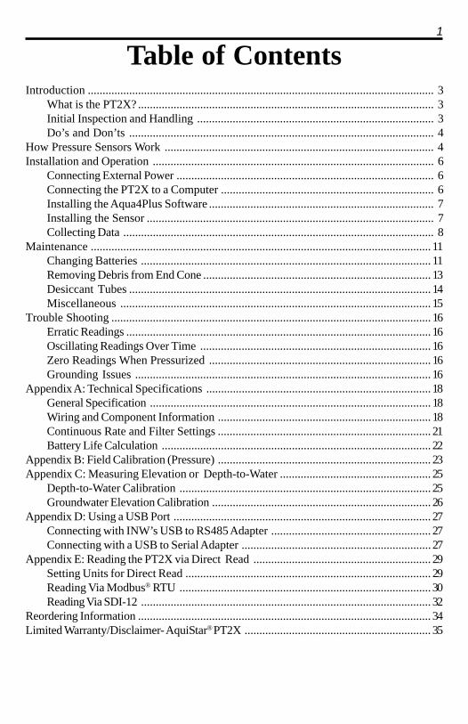
Table of ContentsIntroduction ..................................................................................................................... 3
What is the PT2X? .................................................................................................... 3Initial Inspection and Handling ................................................................................ 3Do’s and Don’ts ....................................................................................................... 4
How Pressure Sensors Work ........................................................................................... 4Installation and Operation ............................................................................................... 6
Connecting External Power ....................................................................................... 6Connecting the PT2X to a Computer ........................................................................ 6Installing the Aqua4Plus Software ............................................................................ 7Installing the Sensor ................................................................................................. 7Collecting Data ......................................................................................................... 8
Maintenance ................................................................................................................... 11Changing Batteries .................................................................................................. 11Removing Debris from End Cone ............................................................................. 13Desiccant Tubes ...................................................................................................... 14Miscellaneous ......................................................................................................... 15
Trouble Shooting ............................................................................................................ 16Erratic Readings ....................................................................................................... 16Oscillating Readings Over Time .............................................................................. 16Zero Readings When Pressurized ........................................................................... 16Grounding Issues .................................................................................................... 16
Appendix A: Technical Specifications ............................................................................ 18General Specification ............................................................................................... 18Wiring and Component Information ........................................................................ 18Continuous Rate and Filter Settings ........................................................................ 21Battery Life Calculation ........................................................................................... 22
Appendix B: Field Calibration (Pressure) ........................................................................ 23Appendix C: Measuring Elevation or Depth-to-Water ................................................... 25
Depth-to-Water Calibration ..................................................................................... 25Groundwater Elevation Calibration .......................................................................... 26
Appendix D: Using a USB Port ....................................................................................... 27Connecting with INW’s USB to RS485 Adapter ...................................................... 27Connecting with a USB to Serial Adapter ................................................................ 27
Appendix E: Reading the PT2X via Direct Read ............................................................ 29Setting Units for Direct Read ................................................................................... 29Reading Via Modbus® RTU ..................................................................................... 30Reading Via SDI-12 .................................................................................................. 32
Reordering Information ................................................................................................... 34Limited Warranty/Disclaimer- AquiStar® PT2X ............................................................... 35

2
Information in this document is subject to change without notice and does not representa commitment on the part of the manufacturer. No part of this manual may bereproduced or transmitted in any form or by any means, electronic or mechanical,including photocopying and recording, for any purpose without the express writtenpermission of the manufacturer.
©1997 - 2011 Instrumentation Northwest, Inc.Registered trademarks and trademarks belong to their respective owners.

3Introduction
What is the PT2X?
INW’s AquiStar® PT2X Smart Sensor is an integrated datalogger and pressure/tempera-ture sensor and is ideal for monitoring groundwater, well, tank and tidal levels, as well asfor pump testing and flow monitoring. This sensor networks with all of the INWAquiStar® Smart Sensor family. Its compatibility with INW’s WaveData® Wireless DataCollection technology makes it ideal for remote monitoring.
This industry standard digital RS485 interface device records up to 520,000 records ofpressure, temperature and time data, operates with low power, and features easy-to-usesoftware with powerful features. Constructed with 316 stainless steel or titanium, Viton®
and PTFE/FE P, this sensor provides high-accuracy readings in rugged and corrosive fieldconditions.
Two internal AA batteries power the PT2X. (Auxiliary power supplies are available fordata intensive applications.) The unit is programmed using INW’s easy-to-useAqua4Plus control software. Once programmed the unit will measure and collect data ona variety of time intervals.
Replace your analog sensor / datalogger with the AquiStar® PT2X as a stand-alone unitor network with other INW AquiStar® Smart Sensors. Most users will use the PT2X withINW’s Aqua4Plus software. However, the PT2X is quite versatile, communicating viaeither Modbus® or SDI-12 interfaces, allowing you to do the following:• Read a PT2X via the Modbus® protocol using your own software.• Read a PT2X via SDI-12 protocol.• Display readings from a PT2X on a panel meter.
If you want to use one of these methods, please contact INW for further details.
Initial Inspection and Handling
Upon receipt of your smart sensor, inspect the shipping package for damage. If anydamage is apparent, note the signs of damage on the appropriate shipping form. Afteropening the carton, look for concealed damage, such as a cut cable. If concealeddamage is found, immediately file a claim with the carrier.
Check the etched label on the sensor to be sure that the proper range and type wereprovided. Also check the label attached to the cable at the connector end for the propercable length.

4
Do’s and Don’ts
How Pressure Sensors Work
Liquids and gasses do not retain a fixed shape. Both have the ability to flow and areoften referred to as fluids. One fundamental law for a fluid is that the fluid exerts anequal pressure in all directions at a given level. Further, this pressure increases with anincreasing depth of “submergence”. If the density of a fluid remains constant(noncompressible...a generally good assumption for water at “normal” pressures andtemperatures), this pressure increases linearly with the depth of “submergence”.
We are all “submerged” in the atmosphere. As we increase our elevation, the pressureexerted on our bodies decreases as there is less of this fluid above us. It should benoted that atmospheric pressure at a given level does vary with changes in the weather.One standard atmosphere (pressure at sea level at 20º C) is defined to be 14.7 PSI(pounds per square inch).
There are several methods to reference a pressure measurement. Absolute pressure ismeasured with respect to an ideal vacuum (no pressure). Gauge pressure is the mostcommon way we express pressure in every day life and is the pressure exerted over andabove atmospheric pressure. With this in mind, gauge pressure (Pg) can be expressedas the difference between the absolute pressure (Pa) and atmospheric pressure (Patm):
Pg = Pa - Patm.
To measure gauge pressure, atmospheric pressure is subjected to one side of thesystem and the pressure to be measured is subjected to the other. The result is that thedifferential (gauge pressure) is measured. A tire pressure gauge is a common exampleof this type of device.
Recall that as the level of submergence increases (in a noncompressible fluid), thepressure increases linearly. Also, recall that changes in weather cause the absoluteatmospheric pressure to change. In water, the absolute pressure (Pa) at some level ofdepth (d) is given as follows:
Pa = Patm + kd
where k is simply a constant (i.e.: 2.307 feet of water = 1 PSI)
Do handle the device with care.Do store the device in a dry, inside area when
not in use.Do install a desiccant tube if using a gauge
sensor.Do install the device so that the connector
end is kept dry.
Don’t support the device with the connector.Use a strain relief device to take thetension off the connectors.
Don’t allow the device to free-fall down awell as impact damage can occur.
Don’t bang or drop the device on hardobjects.

5INW’s standard gauge submersible pressure devices utilize a vent tube in the cable toallow the device to reference atmospheric pressure. The resulting gauge pressuremeasurement reflects only the depth of submergence. That is, the net pressure on thediaphragm is due entirely to the depth of submergence.
Pressure Diagram: See detail A on next page.
Absolute pressure is given as Pa = Patm + kd (where kis 2.307 feet of water)

6
Installation and Operation
Connecting External Power
The PT2X comes with two AA internal batteries. This provides enough power for atleast one year of operation at the rate of four measurements per hour. (See Battery LifeCalculation section in Appendix A for further details.)
If auxiliary power is desired, you can use a 6 - 13 VDC supply that can provide 15 mA.Connect to Vaux++ (pin 1 - white) and Ground (pin 5 - blue) or contact INW for auxiliarypower supplies.
Connecting the PT2X to a Computer
In its cabled configuration, the Smart Sensor cable is terminated with a weather-resistantconnector. In its cableless configuration, the PT2X is terminated with a weather-resistant connecter inside a screw-cap. Connect the weather-resistant connector to yourPC or laptop serial port via the interface cable and an RS485/RS232 adapter, as shownbelow. For USB connections, see Appendix D.
Connect the sensor to your computer using the interface cable and anRS485/RS232 adapter. See Appendix D for details on connectingusing a USB Port.
RS485/RS232AdapterWeather-
resistantConnectors Serial Port
PT2XCableless Configuration
Interface Cable
PC orLaptop
Computer
Screw-
PT2X
cap
PC orLaptop
Computer
RS485/RS232Adapter
Interface Cable
Weather-resistant
Connectors
Serial Port
PT2X
PT2XCable
Cabled Configuration

7Installing the Aqua4Plus Software
The PT2X comes with the Aqua4Plus host software that is installed on your PC orlaptop. Use this software to program the datalogger, to retrieve data from the logger, toview collected data, and to export data to external files for use with spreadsheets ordatabases.
Refer to the Aqua4Plus software manual for details on installing and using Aqua4Plus.
Using the PT2X Without Aqua4Plus
Most users will use the PT2X with INW’s Aqua4Plus software. However, the PT2X isquite versatile, communicating via either Modbus® or SDI-12 interfaces, allowing you todo the following:
• Read a PT2X via the Modbus® protocol using your own software.
• Read a PT2X via SDI-12 protocol.
• Display readings from a PT2X on a panel meter.If you want to use one of these methods, please contact INW for further details.
Installing the Sensor
The PT2X measures pressure. The most common application is measuring liquid levelsin wells and tanks. In order to do this, the sensor must be installed below the waterlevel at a fixed depth. The installation depth depends on the range of the sensor. One(1) PSI is equal to approximately 2.31 feet of water. If you have a 5 PSI sensor, the rangeis 11.55 feet of water and the sensor should not be installed at a depth below 11.55 feet.If the sensor is installed below its maximum range, damage may result to the sensor andthe output reading will not be correct.
Lower the sensor to the desired depth. Fasten the cable to the well head using tiewraps or a weather proof strain-relief system. When securing a vented cable, make surenot to pinch the cable too tightly or the vent tube inside the cable jacket may be sealedoff. Take a measurement to insure the sensor is not installed below its maximum range.
Be sure the supplied cap is securely placed on the weather-resistant connector at thetop of the cable. Do not install such that the connector might become submerged withchanging weather conditions. The connector can withstand incidental splashing but isnot designed to be submerged.
If at all possible, install the sensor so that the desiccant tube will not flood or lie inwater. (Note: Though the hydrophobic filter will prevent water intrusion via thedesiccant tube at one to two feet of submergence, care must still be taken to keep thecable connector from being submerged.)

8
The Real Time Monitor gives a snapshot of thecurrent readings on the sensor.
The sensor can be installed in any position; however, when it leaves the factory it istested in the vertical position. Strapping the sensor body with tie wraps or tape will nothurt it. INW can provide an optional 1/4" NPT input adapter which is interchangeablewith the standard end cone for those applications where it is necessary to directlyattach the sensor to a pipe, tank or other pipe port. If the sensor is being installed in afluid environment other than water, be sure to check the compatibility of the fluid withthe wetted parts of the sensor. INW can provide a variety of seal materials if you areplanning to install the sensor in an environment other than water.
Collecting Data
Following is a brief overview on using Aqua4Plus to collect data. Please refer to theAqua4Plus Instruction Manual for further details on configuring and using Aqua4Plus.
Real Time Monitor
Click Single to get a single reading.
Click Start to get a reading once a second.
Click Stop to stop the reading.
Note: These are snapshot readings and are not recorded on the sensor. On sensors withfirmware versions lower than 2.0, the pressure is displayed in the first column andtemperature in the second. On sensors with firmware versions 2.0 and higher, thetemperature is displayed in the first column and pressure in the second.

9Setting up a Data Recording Session
Click the tool button. A Session Profile Window will open. Refer to the Aqua4PlusInstruction Manual for details in describing your session profile. Click the Start buttonto save the session to the sensor and begin recording.
Using the Session Profile Window, describethe test steps for your particular test.
Retrieving Data from the Sensor/Datalogger
• Click on the session you want to upload.
• Click the tool button.
• Select a file location.
• Click Save.
• Click Start.
Select the data session you areready to upload.

10
Viewing Data
• Click the tool button to view data as a table.
• Click the tool button to view data as a graph.
• Navigate to the desired file, then click the Open button. (If the File Open box doesnot appear, click the File Menu, then select Open.)
The File Display window displays yourdata in a tabular format.
The Graph Window displays your data on an X Ycoordinate graph.

11Exporting Data to .csv or .xls Files
• Using the File Display window, open the file you want to export.
• Click on the tool button.
• Select a file location and enter a name for the file.
• Select a file type.
• Click Save.
A Word About Units
Readings from the PT2X Smart Sensor can be displayed in various units, such as PSI,Ft. H2O, or mm H2O for pressure, or degrees Celsius or degrees Fahrenheit for tempera-ture. Select the units you want from the Options | Units menu.
Maintenance
Changing Batteries
Because changing the batteries involves opening the water-tight seal, this must be donein a clean, dry environment to avoid contamination or moisture damage to the circuitry.
PT2X Smart Sensors come in two housing styles - a twist open version and a set screwversion. Directions follow for each type separately.
The PT2X uses two standard AA Alkaline batteries. A fresh set of batteries should lastup to one year when taking four samples per hour. For details in calculating battery life,see Appendix A.
Twist Open Housing
Opening the HousingOpen the housing by removing the top-cap, as outlined below. The top-cap is theconnector between the tube housing the sensor and the cable.
1. Twisting gently, unscrew the top-cap.
2. Gently separate the top-cap from the body of the sensor. Top-cap remainsattached to body via several colored wires.
Caution! Pulling forcefully on the top-cap can pull the insides out of thesensor or snap the connections inside. Removing the circuit board orpushing on the surface of the pressure element may void your warranty.
Note: O-rings provide a water-tight seal for the sensor housing. Take carenot to nick or otherwise damage these O-rings.

12
On the twist open housing, gently remove the top cap and slide batteries out.
Replacing Batteries
3. Tip housing over and gently slide batteries out.
4. Insert new batteries - positive terminals towards the top-cap.
5. Replace and retighten top-cap.
Set Screw HousingOpen the housing by removing the top-cap, as outlined below. The top-cap is theconnector between the tube housing the PT2X and the cable.Opening the Housing
1. Remove the two set screws at the top of the housing tube, using a 1/16” allenwrench.
2. Very gently work the top cap loose. Note, two O-rings provide a water-tight sealfor the PT2X housing and often seal tightly. Inserting the blade of a flat screw-driver between the top-cap and the housing and twisting gently can help torelease the O-rings’ seal. Then rock the top-cap back and forth, while applyingsteady, but controlled, upward pressure.
Caution! Pulling forcefully on the top-cap can cause the O-rings torelease suddenly and the top-cap to disengage with enough force topull the insides out of the sensor or snap the connections inside.Removing the circuit board or pushing on the surface of the pressureelement may void your warranty.
Note: O-rings provide a water-tight seal for the sensor housing. Takecare not to nick or otherwise damage these O-rings.
Replacing the Batteries
3. Remove the black service connector.
4. Tip housing over and gently slide batteries out.
5. Insert new batteries - positive terminals towards the top-cap.

13Re-sealing the Housing
6. Replace service connector. Note: this connector is keyed and can only beconnected in one direction.
7. Carefully wrap the cable around the slot in the connector board.
8. Replace top-cap and secure with set screws.
On the set screw housing, gently remove the service connector before replacingbatteries. Carefully replace the connector once batteries have been replaced.
Removing Debris from End Cone
At times mud, silt, or other debris may foul the water inlets to the pressure element. Theend cone can be removed to clean out the debris.
Twist Open Housing
1. Gently twist off end cone portion only - do not twist off pressure element!
2. Remove debris. Take care not to poke anything into the sensor. This can damagethe sensor element and void the warranty.
3. Replace and retighten the end cone.
Gently twist off the end cone, and then carefully remove debris.
ServiceConnector
Pressure element
Water inlet
End cone

14
Set Screw Housing
1. Remove the two set screws at the bottom of the housing tube, using a 1/16” allenwrench.
2. Gently remove the end cone.
3. Remove debris. Take care not to poke anything into the sensor. This can damagethe sensor element and void the warranty.
4. Replace the end cone and secure with set screws.
Remove end cone by removing set screws. Gently clean out debris.
Desiccant Tubes
On vented sensors, inspect the desiccant tube at least once every two months. Thedesiccant tube prevents moisture in the air from being sucked into the vent tube, whichcan cause erratic readings and sensor damage.
The desiccant tube is filled with blue silica gel beads. A locking barb and a hydrophobicwater filter are attached to the end of the desiccant tube. This filter prolongs the life ofthe desiccant as much as three times over a desiccant tube without the filter. This filteralso prevents water intrusion should the desiccant tube be submerged under one to twofeet of water.
If at all possible, install the sensor so that the desiccant tube will not flood or lie inwater. (Note: Though the hydrophobic filter will prevent water intrusion via thedesiccant tube, care must still be taken to keep the cable connector from beingsubmerged.)
The desiccant is a bright blue color when active and dry. As moisture is absorbed thecolor will begin to fade, becoming a light pink, which indicates full saturation and time toreplace. Replacement desiccant and hydrophobic filters can be purchased from INW;please contact an INW sales engineer at 1-800-776-9355 for more information.
Pressure element
Water inlet
End cone
Set screw

15
The desiccant tube prevents water intrusion through the vent tube. Be sure toreplace the desiccant when it turns pink, as that indicates it is saturated.
Miscellaneous
Sensor: There are no user-serviceable parts, other than the batteries. If problemsdevelop with sensor stability or accuracey, contact INW. If the transducers have beenexposed to hazardous materials, do not return them without notification andauthorization.
Cable: Cable can be damaged by abrasion, sharp objects, twisting, crimping, crushing,or pulling. Take care during installation and use to avoid cable damage. If a section ofcable is damaged, it is recommended that you send your sensor back to replace thecable harness assembly.
End Connections: The contact areas (pins & sockets) of the connectors will wear outwith extensive use. If your application requires repeated connections other types ofconnectors can be provided. The connectors used by INW are not submersible, but aredesigned to be splash-resistant.
Vent tube
Weather-resistantconnector
Cable
Desiccant tubeHydrophobic filter

16
Trouble Shooting
Erratic Readings
Erratic readings can be caused by a poor connection, damaged cable, moisture in theunit, or a damaged transmitter. In most cases, erratic readings are due to moisturegetting into the system. The first thing to check is the connection. Look for moisturebetween contacts or a loose or broken wire. Next, check the cable for cracking orfraying. If the connections and cable appear OK, but the readings are still erratic, thetransmitter may be damaged. Contact INW for evaluation and repair. Erratic anderroneous readings can also occur due to improper grounding. See Grounding Issues,below.
Oscillating Readings Over Time
If, after time, your transmitter is functioning normally but your data is showing a cycliceffect in the absence of water level changes, you are probably seeing barometricchanges. The amount is usually .5 to 1.5 feet of water. This can be caused by aplugged vent tube in the cable or actual water level changes in the aquifer itself inresponse to barometric pressure changes. This effect can occur in tight formationswhere the transmitter will immediately pick up barometric changes but the aquifer willnot. If you think you are having this type of problem you will have to record thebarometric pressure as well as the water level pressure and compensate the data. If itappears that the vent tube is plugged, consult the factory.
If a desiccant tube is not installed in line with the cable, water may have condensed inyour vent tube causing it to plug. After you are finished installing the desiccant tubeyou can test the vent tube by applying a small amount of pressure to the end of thedesiccant tube and seeing if this affects the transmitter reading.
Zero Readings When Pressurized
Continuous zero readings are usually caused by an open circuit which may indicate abroken cable, a bad connection, or possibly a damaged transmitter. Check theconnector to see if a wire has become loose or if the cable has been cut. If damage isnot readily apparent, contact INW for evaluation and repair.
Grounding Issues
It is commonly known that when using electronic equipment, both personnel andequipment need to be protected from high power spikes that may be caused bylightning, power line surges, or faulty equipment. Without a proper grounding system, a

17power spike will find the path of least resistance to earth ground – whether that path isthrough sensitive electronic equipment or the person operating the equipment. In orderto ensure safety and prevent equipment damage, a grounding system must be used toprovide a low resistance path to ground.
When using several pieces of interconnected equipment, each of which may have itsown ground, problems with noise, signal interference, and erroneous readings may benoted. This is caused by a condition known as a Ground Loop. Because of naturalresistance in the earth between the grounding points, current can flow between thepoints, creating an unexpected voltage difference and resulting erroneous readings.
The single most important step in minimizing a ground loop is to tie all equipment(sensors, dataloggers, external power sources and any other associated equipment) to asingle common grounding point. INW recommends connecting the shield to ground atthe connector end.

18
Appendix A: Technical Specifications
General SpecificationThe AquiStar® PT2X is a microprocessor based digital intelligent sensor designed tomeasure and record pressure, temperature and time, utilizing state-of-the-art low power,battery operated circuitry.
Pressure is measured with an extremely rugged and stable piezo-electric media-isolatedpressure element combined with a 16-bit delta/sigma analog-to-digital converter. Thisprovides extremely accurate and stable pressure input into the microprocessor on thecircuit board. Temperature is measured with a digital temperature chip. The data is storedin non-volatile memory. A serial communication link (RS485) provides communication tothe host computer.
Wiring and Component Information
For Modbus® withfirmware lower than 2.0— with 5-pin connector
For Modbus® withfirmware 2.0 or higher— with 5-pin connector
For SDI-12 withfirmware 2.0 or higher— with 5-pin connector
For SDI-12 withfirmware 2.0 or higher— without connector
WhitePurpleYellowBrownBlueShield
12 VDC+ (Vaux)Modbus D-Modubs D+Digital I/O (Not used)Ground
12345
5-Pin Connector
WhitePurpleYellowBrownBlueShield
12 VDC+ (Vaux)Modbus D-Modubs D+SDI-12 (Not used)Ground
12345
5-Pin Connector
WhitePurpleYellowBrownBlueShield
12 VDC+ (Vaux)Modbus D- (Not used)Modubs D+ (Not used)SDI-12 Signal12 VDC – (Gnd)
12345
5-Pin Connector
WhitePurpleYellowBrownBlueShield (may be green)
12 VDC+ (Vaux)Modbus D- (Not used)Modubs D+ (Not used)SDI-12 Signal12 VDC – (Gnd)Earth ground
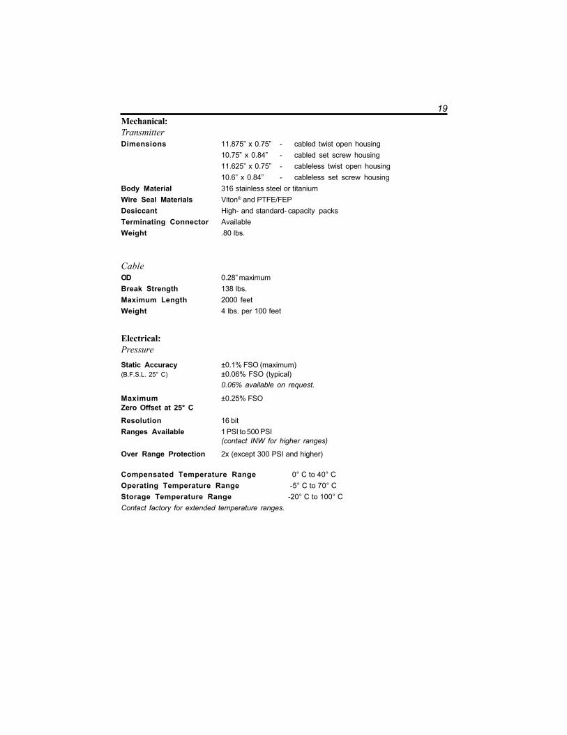
19Mechanical:TransmitterDimensions 11.875” x 0.75” - cabled twist open housing
10.75” x 0.84” - cabled set screw housing11.625” x 0.75” - cableless twist open housing10.6” x 0.84” - cableless set screw housing
Body Material 316 stainless steel or titaniumWire Seal Materials Viton® and PTFE/FEPDesiccant High- and standard- capacity packsTerminating Connector AvailableWeight .80 lbs.
CableOD 0.28” maximumBreak Strength 138 lbs.Maximum Length 2000 feetWeight 4 lbs. per 100 feet
Electrical:PressureStatic Accuracy ±0.1% FSO (maximum)(B.F.S.L. 25° C) ±0.06% FSO (typical)
0.06% available on request.
Maximum ±0.25% FSOZero Offset at 25° C
Resolution 16 bitRanges Available 1 PSI to 500 PSI
(contact INW for higher ranges)
Over Range Protection 2x (except 300 PSI and higher)
Compensated Temperature Range 0° C to 40° COperating Temperature Range -5° C to 70° CStorage Temperature Range -20° C to 100° CContact factory for extended temperature ranges.

20
Sensor Components
Cabled Version Cableless Version
End Cone -interchangeable with1/4” NPT
Pressure Element
PT2X Sensor/DataloggerCircuit Board, containingnon-volatile data storage
User-replaceableAA batteries
Service Connector
Patented Cable Harness(Top-Cap)
Vented or Unvented Cable
Water Inlets
O-Rings
Screw Cap
0.75”Twist Open Housing
0.84”Set Screw Housing
10.7
5” -
Set
Scr
ew H
ousi
ng
11.8
75” T
wis
t Ope
n H
ousi
ng
0.75”Twist Open Housing
0.84”Set Screw Housing
11.6
25” T
wis
t Ope
n H
ousi
ng
10.6
” Set
Scr
ew H
ousi
ng

21Continuous Rate and Filter Settings
Continuous Rate:
The PT2X can take readings more often than once per second. This is known as a“continuous rate.” Set the continuous rate for the PT2X from the Configure Menu | SensorContinuous Rate.
Firmware Version Available settings
1.0 and above Exactly 2, 4, or 8 readings per second
0.22, 0.23, 0.24 Approximately 2, 3, 4, 5, 6, or 10 readings per second
0.18 Approximately 10 readings per second
To use the continuous rate during a session, enter a “c” in the Polling Interval.
Filter Settings:
The PT2X has the ability to apply some filtering to incoming data in order to smooth outminor variations in readings. This filter can be from 1 (no filtering) to 8 (maximum filtering.)Different versions of firmware have different filtering options as shown below. For furtherinformation on PT2X data filtering, see INW application note Filter Response on PT2XSmart Sensor (9C0530).
Firmware Version Filtering
1.3 and above Can be set from 1 (no filtering) to 8 (maximum filtering) from theAdvanced option on the Configure menu.
1.0 - 1.2 Filter is set to 1 (no filtering). Adjustable filtering can beobtained by upgrading to a higher firmware version.
0.24 Filter is permanently set to 1 (no filtering).
0.23 and lower Filter is permanently set to 8 (maximum filtering).

22
Battery Life Calculation
The PT2X has been designed for very low power consumption. When not in active use,the unit goes into a “sleep” mode, waking only to take readings or communicate withthe host computer.
It is difficult to know how fresh particular batteries are. Just sitting on a shelf, especiallyin a warm environment, will cause the batteries to lose energy. If the batteries are storedin a cold environment, the self-discharge will be less, but the batteries won't provide asmuch energy output when they're cold. Under optimum conditions, two fresh AAalkaline batteries should provide 15,000 Joules of energy. To give yourself some margin,INW recommends that you assume approximately 12,000 Joules.
When sleeping, the PT2X consumes approximately 150 Joules per week. Each readingconsumes approximately .075 Joules. Communicating with the sensor for one minute, toupload data or take real-time readings, for instance, consumes approximately two Joules.
Use the following formulas to calculate your battery life:
Compute Weekly usage:Readings usage = number of readings per hour * 24 hours * 7 days * .075 JoulesCommunications usage = minutes of communication per week * 2 JoulesSleep time usage = 150 JoulesTotal weekly usage = reading + communication + sleep usage
Compute life of batteries:Life of batteries in weeks = 12,000 Joules / Total weekly usage
Example:4 readings per hour, 1 minute of communication per week
Readings usage = 4 * 24 hours * 7 days * .075 Joules = 50 JoulesCommunication usage = 1 * 2 Joules = 2 JoulesSleep time usage = 150 JoulesTotal weekly usage = 50 + 2 + 150 = 202 JoulesLife of battery = 12,000 / 202 = 59 weeks (approximate)

23
Appendix B: Field Calibration (Pressure)
Calibration can only be done when there are no sessions stored on the sensor. If thereare any sessions stored on the sensor, upload any data you want and then erase thesession before continuing.
Before leaving the factory, your PT2X has been calibrated using precision pressuresources and thermal chambers. However, you may wish to run a field calibration fromtime to time for one or more of the following reasons.
• You want to set a specific zero reference point - use a 1- or 2-point calibration.• You suspect you may have some zero drift on your sensor - use a 1- or 2- point
calibration.• You suspect you may have some gain drift on your sensor (rare) - use a 2-point
calibration.• You are measuring in a fluid with a density other than that of fairly pure fresh
water - use a 2-point calibration.
Preparation:• Run Aqua4Plus and scan for sensors.• On the Sensor Map, click the sensor you want to calibrate.• From the Options Menu, select the units you want to use to measure pressure,
i.e., psi, feet of water, inches of mercury, etc.• From the Configure Menu, select Field Calibration.• Click on Pressure in the left panel.
One-Point Calibration:— Computing Calibration Value —• Place sensor in the fluid you are measuring at a precise known level.• In the Ref box for the first point, enter this level or pressure.• Click first Measure button.• When readings have stabilized to your satisfaction, click the OK button in the
pop-up box.
— Applying Calibration Value —• Click the Apply button to apply calibration value.• The computed b value will be transferred to the calibration field.• Click OK to save the value to the sensor.
— Verifying Calibration Value —• Using the Real Time Monitor, take a few readings while the sensor is still at the
precise known level. Readings should be very close to that level.

24
Two-Point Calibration:— Compute First Calibration Point —• Place sensor in the fluid you are measuring at a precise known level.• In the Ref box for the first point, enter this level or pressure.• Click first Measure button.• When readings have stabilized to your satisfaction, click the OK button in the
pop-up box.
— Compute Second Calibration Point —• Place sensor in the fluid you are measuring at a second precise known level.• In the Ref box for the second point, enter this level or pressure.• Click second Measure button.• When readings have stabilized to your satisfaction, click the OK button in the
pop-up box.
— Applying Calibration Values —• Click the Apply button to apply calibration values.• The computed m and b values will be transferred to the calibration fields.• Click OK to save the values to the sensor.
— Verifying Calibration Values —• Using the Real Time Monitor, take a few readings while the sensor is still at the
second precise known level. Readings should be very close to that level.

25
Appendix C: Measuring Elevation or Depth-to-Water
The purpose of this appendix is to provide a simple description for configuring a PT2XSmart Sensor for monitoring depth-to-water or groundwater elevation, using theAqua4Plus Control Software.
In normal configuration, the PT2X returns a pressure measurement relative to the waterabove the sensor. This can be expressed in psi, feet of water, inches of mercury, or anumber of other units - however, it is always relative to the water above the sensor.
Often an engineer will need to know the depth-to-water or the elevation of the water.Using Aqua4Plus’ field calibration abilities, the PT2X can be configured to displaydepth-to-water or elevation.
Depth-to-Water Calibration
NOTE: When using Depth-To-Water, you may want to change the channel label atthe top of the Field Calibration window to read “Depth”. (Label not available onPT2X version 1.5 or earlier.)
— Computing Offset —• Checkmark the box labeled Compute pressure as depth to water.• If you are using a gauge (PSIG) sensor:
1. Using a water level indicator or other measuring device, determine thedepth to water.
2. Enter this level in the Ref box.• If you are using an absolute (PSIA) sensor * :
1. Using a water level indicator or other measuring device, determine thedepth to water.
2. Obtain the current barometric reading from another device. (Note: be sureto use the same units as you are using in Aqua4Plus, e.g., if you are usingFt H2O in Aqua4Plus, use Ft H2O on the barometric reading.)
3. Subtract the barometric reading from the value you read from the waterlevel indicator.
4. Enter this level in the Ref box.• Click the Measure button.• When readings have stabilized to your satisfaction, click the OK button in the
pop-up box.
— Applying Calibration Values —• Click the Apply button to apply calibration values.• The computed m and b values will be transferred to the calibration fields.
• Click OK to save the values to the sensor.
26
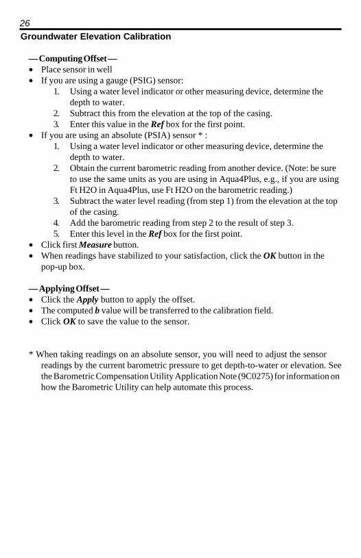
Groundwater Elevation Calibration
— Computing Offset —• Place sensor in well• If you are using a gauge (PSIG) sensor:
1. Using a water level indicator or other measuring device, determine thedepth to water.
2. Subtract this from the elevation at the top of the casing.3. Enter this value in the Ref box for the first point.
• If you are using an absolute (PSIA) sensor * :1. Using a water level indicator or other measuring device, determine the
depth to water.2. Obtain the current barometric reading from another device. (Note: be sure
to use the same units as you are using in Aqua4Plus, e.g., if you are usingFt H2O in Aqua4Plus, use Ft H2O on the barometric reading.)
3. Subtract the water level reading (from step 1) from the elevation at the topof the casing.
4. Add the barometric reading from step 2 to the result of step 3.5. Enter this level in the Ref box for the first point.
• Click first Measure button.• When readings have stabilized to your satisfaction, click the OK button in the
pop-up box.
— Applying Offset —• Click the Apply button to apply the offset.• The computed b value will be transferred to the calibration field.• Click OK to save the value to the sensor.
* When taking readings on an absolute sensor, you will need to adjust the sensorreadings by the current barometric pressure to get depth-to-water or elevation. Seethe Barometric Compensation Utility Application Note (9C0275) for information onhow the Barometric Utility can help automate this process.
27
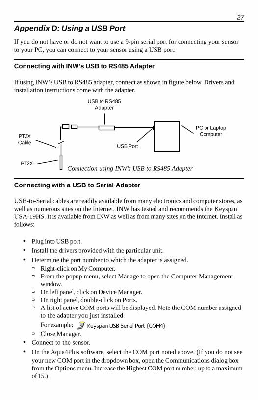
Appendix D: Using a USB Port
If you do not have or do not want to use a 9-pin serial port for connecting your sensorto your PC, you can connect to your sensor using a USB port.
Connecting with INW’s USB to RS485 Adapter
If using INW’s USB to RS485 adapter, connect as shown in figure below. Drivers andinstallation instructions come with the adapter.
Connection using INW’s USB to RS485 Adapter
Connecting with a USB to Serial Adapter
USB-to-Serial cables are readily available from many electronics and computer stores, aswell as numerous sites on the Internet. INW has tested and recommends the KeyspanUSA-19HS. It is available from INW as well as from many sites on the Internet. Install asfollows:
• Plug into USB port.
• Install the drivers provided with the particular unit.
• Determine the port number to which the adapter is assigned. Right-click on My Computer. From the popup menu, select Manage to open the Computer Management
window. On left panel, click on Device Manager. On right panel, double-click on Ports. A list of active COM ports will be displayed. Note the COM number assigned
to the adapter you just installed.
For example: Close Manager.
• Connect to the sensor.
• On the Aqua4Plus software, select the COM port noted above. (If you do not seeyour new COM port in the dropdown box, open the Communications dialog boxfrom the Options menu. Increase the Highest COM port number, up to a maximumof 15.)
PC or LaptopComputer
USB Port
USB to RS485Adapter
PT2X
PT2XCable

28
InterfaceCable
PC or LaptopComputer
USB PortUSB-to-Serial
Adapter
RS232/RS485Adapter
PT2X
PT2XCable
Connection using a USB to Serial Adapter

29
Appendix E: Reading the PT2X via Direct Read
While the PT2X comes with INW’s easy to use Aqua4Plus software, you can also usestandard Modbus® RTU or SDI-12 equipment to easily take readings, so as to tie intoyour existing equipment or networks.
You may need to use Aqua4Plus to make a few settings, prior to directly reading thePT2X with your equipment. For one thing, you may want to change the units forreturned values. If reading via Modbus, you may also need to set the baud rate. (You donot need to set the baud rate for SDI-12). These are described in the following sections.
For Modbus direct read, you must have PT2X firmware 1.5 or higher. For SDI-12, youmust have firmware 2.0 or higher.
Setting Units for Direct Read
By default, the PT2X uses the following units:Temperature Degrees CelsiusPressure PSI
However, you can select from a variety of units for direct read measurements. If youwant to change to different units, for example, degrees Fahrenheit for temperature or feetof water for pressure, set these units using Aqua4Plus.
• Click on the Configure menu, and then select Advanced.
• From the flyout menu, select Direct Read Units.
• On the popup box, click the down-arrows next to the channel types you want tochange, and then select the units you want.
• Click OK
Use Aqua4Plus to select the units for your directread measurements, whether Modbus or SDI-12.
Once set, these units are saved on the sensor and direct readings, either via Modbus orvia SDI-12, will return values using these units. (Note: These settings do not affect theunits used on the Aqua4Plus display. Refer to the Aqua4Plus software manual for detailson using Aqua4Plus.)
30
Reading Via Modbus® RTU
Setting Baud RateYour PT2X comes configured to communicate at 38,400 baud, with 8 data bits, one stopbit, and no parity. The sensor can also be set to 19,200 or 9600 baud, if needed for yourapplication.
If needed, set your PT2X to the desired baud rate as follows:• Click on the Configure menu, and then select Advanced.
• From the flyout menu, select Sensor Baud Rate. (You may be asked for apassword. Enter admin.)
• On the popup box, click the down-arrow and select the baud rate you need, andthen click OK.
Once you have changed the baud rate on the PT2X, you will not be able to talk to itwith Aqua4Plus until you change the baud rate for Aqua4Plus, as follows:
• Click the Options menu, and then select Baud Rate.
• On the popup box, click the down-arrow, select the baud rate you need, and thenclick OK.
The current Aqua4Plus baud rate is displayed in the lower right corner of the mainAqua4Plus window.
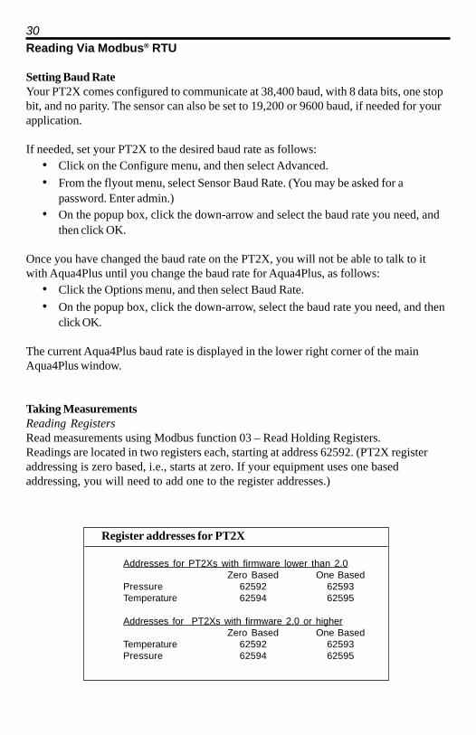
Taking MeasurementsReading RegistersRead measurements using Modbus function 03 – Read Holding Registers.Readings are located in two registers each, starting at address 62592. (PT2X registeraddressing is zero based, i.e., starts at zero. If your equipment uses one basedaddressing, you will need to add one to the register addresses.)
Register addresses for PT2X
Addresses for PT2Xs with firmware lower than 2.0Zero Based One Based
Pressure 62592 62593Temperature 62594 62595
Addresses for PT2Xs with firmware 2.0 or higherZero Based One Based
Temperature 62592 62593Pressure 62594 62595

31Measurement TimingWhen you request a reading via Modbus, the sensor wakes up, returns the currentvalues in the registers, and then starts taking new readings and updating the registers.After approximately 10 seconds, if no more readings have been requested, the sensorgoes back to sleep.
Because of this, the first reading you get will be old. If you are taking readings atintervals of less than 10 seconds, simply ignore the first reading — all remainingreadings will be current. On the other hand, if you are taking readings at intervals ofgreater than 10 seconds, take a reading, ignore it, wait one second, take another reading.Record this second reading.
Data FormatThe data is returned as 32-bit IEEE floating-point values, high word first, also referred toas big-endian or float inverse.
For further information and detailed Modbus examples, see INW application note,“Modbus Direct Read on AquiStar Smart Sensors” available from our web site at http://www.inwusa.com/appnotes.htm.

32
Reading Via SDI-12
Note: The default units setting for pressure is PSI. The default units setting for temperature isCelsius. To change these, use the Direct Read Units option under the Configure | Advanced menuin the Aqua4Plus Control Software.
AddressingDefault SDI-12 Address: 0
SDI-12 Command Nomenclature<a> = Sensor address{crc} = SDI-12 compatible 3-character CRC<cr> = ASCII carriage return character<lf> = ASCII line feed characterhighlighted values indicate variable data
SDI-12 Commands//*** Sensor Identification<a>I! <a>13 INWUSA PT2X2.1ssssssssss<cr><lf>
// note: 2.1 will change to reflect current// firmware revision// ssssssssss = device serial #
//*** Acknowledge Active, Address Query<a>! <a><cr><lf>?! <a><cr><lf>
//*** Change Address<a>A<b>! <b><cr><lf> // change address to <b>
//*** Request measurement<a>M! <a>0022<cr><lf> // request all measurements<a>D0! <a>+22.0512+12.0512<cr><lf> // read temperature
// pressure
<a>M1! <a>0021<cr><lf> // request temperature measurement only<a>D0! <a>+22.0512<cr><lf> // read temperature
<a>M2! <a>0021<cr><lf> // request pressure measurement only<a>D0! <a>12.0512<cr><lf> // read pressure

33//*** Request measurement with CRC<a>MC! <a>0022<cr><lf> // request all measurements with CRC<a>D0! <a>+22.0512+12.0512{crc}<cr><lf> // read temperature
// pressure
<a>MC1! <a>0021<cr><lf> // request temperature measurement only// with CRC
<a>D0! <a>+22.0512{crc}<cr><lf> // read temperature
<a>MC2! <a>0021<cr><lf> // request pressure measurement only// with CRC
<a>D0! <a>12.0512{crc}<cr><lf> // read pressure
//*** Concurrent measurement<a>C! <a>00202<cr><lf> // request all measurements<a>D0! <a>+22.0512+12.0512<cr><lf> // read temperature
// pressure
<a>C1! <a>00201<cr><lf> // request temperature measurement only<a>D0! <a>+22.0512<cr><lf> // read temperature
<a>C2! <a>00201<cr><lf> // request pressure measurement only<a>D0! <a>12.0512<cr><lf> // read pressure
//*** Concurrent measurement with CRC<a>CC! <a>00202<cr><lf> // request all measurements with CRC<a>D0! <a>+22.0512+12.0512{crc}<cr><lf> // read temperature
// pressure
<a>CC1! <a>00201<cr><lf> // request temperature measurement only// with CRC
<a>D0! <a>+22.0512{crc}<cr><lf> // read temperature
<a>CC2! <a>00201<cr><lf> // request pressure measurement only// with CRC
<a>D0! <a>12.0512{crc}<cr><lf> // read pressure
For further information and SDI-12 examples, see INW application note, “PT2X SDI-12Interface Specification” available from our web site atwww.inwusa.com/pdfs/pt2x_sdi12_spec.pdf

34
Reordering Information
For sales & service offices, please contact:
Instrumentation Northwest, Inc.www.inwusa.com
800-776-9355

35
LIMITED WARRANTY/DISCLAIMER - AquiStar® PT2XSUBMERSIBLE PRESSURE /TEMPERATURE SENSOR
A. Seller warrants that products manufactured by Seller when properly installed, usedand maintained with a properly installed desiccant tube, shall be free from defects inmaterial and workmanship. Seller’s obligation under this warranty shall be limited toreplacing or repairing the part or parts or, at Seller’s option, the products which provedefective in material or workmanship within ONE (1) year from the date of delivery,provided that Buyer gives Seller prompt notice of any defect or failure and satisfactoryproof thereof. Any defective part or parts must be returned to Seller’s factory or to anauthorized service center for inspection. Buyer will prepay all freight charges to returnany products to Seller’s factory, or any other repair facility designated by Seller. Sellerwill deliver replacements for defective products to Buyer (ground freight prepaid) tothe destination provided in the original order. Products returned to Seller for whichSeller provides replacement under this warranty shall become the property of Seller.
This limited warranty does not apply to lack of performance caused by abrasive materials,corrosion due to aggressive fluids, mishandling or misapplication. Seller’s obligations underthis warranty shall not apply to any product which (a) is normally consumed in operation, or (b)has a normal life inherently shorter than the warranty period stated herein.
In the event that equipment is altered or repaired by the Buyer without prior written approval bythe Seller, all warranties are void. Equipment and accessories not manufactured by the Sellerare warranted only to the extent of and by the original manufacturer’s warranty.
THE FOREGOING WARRANTIES ARE IN LIEU OF ALL OTHER WARRANTIES,WHETHER ORAL, WRITTEN, EXPRESSED, IMPLIED OR STATUTORY. IMPLIEDWARRANTIES OF FITNESS AND MERCHANTABILITY SHALL NOT APPLY. SELLER’SWARRANTY OBLIGATIONS AND BUYER’S REMEDIES THEREUNDER (EXCEPT AS TOTITLE) ARE SOLELY AND EXCLUSIVELY AS STATED HEREIN. IN NO CASE WILLSELLER BE LIABLE FOR CONSEQUENTIAL DAMAGES, LABOR PERFORMED INCONNECTION WITH REMOVAL AND REPLACEMENT OF THE SENSOR SYSTEM,LOSS OF PRODUCTION OR ANY OTHER LOSS INCURRED BECAUSE OF INTERRUP-TION OF SERVICE. A NEW WARRANTY PERIOD SHALL NOT BE ESTABLISHED FORREPAIRED OR REPLACED MATERIAL, PRODUCTS OR SUPPLIES. SUCH ITEMSSHALL REMAIN UNDER WARRANTY ONLY FOR THE REMAINDER OF THE WAR-RANTY PERIOD ON THE ORIGINAL MATERIALS, PRODUCTS OR SUPPLIES.
B. With respect to products purchased by consumers in the United States for personal use, theimplied warranties including but not limited to the warranties of merchantability and fitness for aparticular purpose, are limited to twelve (12) months from the date of delivery.
Some states do not allow limitations on the duration of an implied warranty, so the abovelimitation may not apply to you. Similarly, some states do not allow the exclusion or limitationof consequential damages, so the above limitation or exclusion may not apply to you. Thislimited warranty gives you specific legal rights; however, you may also have other rights whichmay vary from state to state.

8902 122nd Avenue NEKirkland, WA 98033 USA 425-822-4434FAX 425-822-8384 / [email protected]
INW
AquiStar® PT2XPressure/Temperature Smart Sensor and Datalogger
©1997 - 2011 by Instrumentation Northwest, Inc. All rights reserved. Instrumentation Northwest and INW are trademarks registered with the U.S. Patent & Trademark Offi ce. Doc# 9B0730r11 05/2011 / PN 6D275-NI
INSTRUCTION MANUAL