april, 2009 erl srf cryo modules and cryogenic system
TRANSCRIPT
April , 2009
ERL SRF CRYO MODULES
AND CRYOGENIC SYSTEM

G-5 and final ERL configuration
Cryogenics system identical, except elevation change of SCRFGun requires rework of piping to Gun cryomodule
Helium supplies 3 atm, 4.5K helium to cryomodulesThermal Transition InterceptsCavities Reservoir bathRecovery heat exchanger to recovery ref between 2K and 4K. Low pressure helium return through ambient vaporzier to warm process vacuum pump
LN2 distribution to cryomodule shields and Cathode cooling
G-5 CRYOGENIC SYSTEM
DWR-PORTABLE
HXXXM
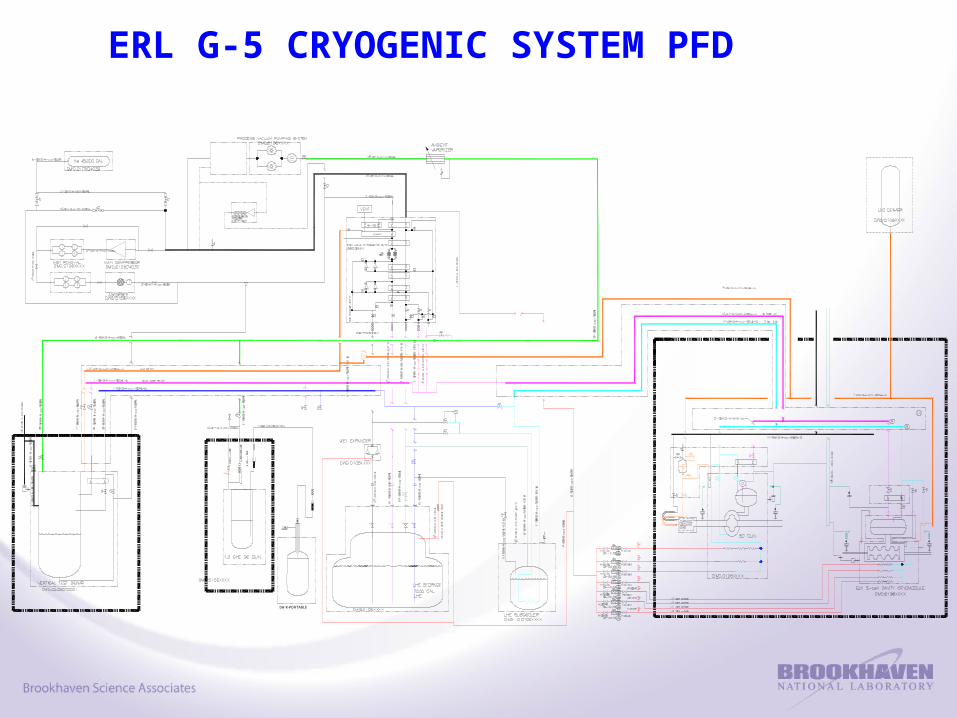
ERL G-5 CRYOGENIC SYSTEM PFD

Stream 1 Stream 2 Stream3 Stream4
Main Helium Compressor +ORS
50 g/s308 K, 17 atm
50 g/s280 K, 1 atm
1660 Coldbox 50 g/s308 K, 16 atm
47-50 g/s280 K,1 atm
12 - 20 g/s4.8 – 6.0 K12 / 1.5 atm
9 -17 g/s4.5 K,1.25 atm
LHe dewar 12-20 g/s4.6 K, 1.4 atm
12-20 g/s4.6 K, 1.4 atm
3-7 g/s4.6K, 1.4 atm
Wet expander 10-15 g/s6 - 7K, 12 atm
10-15 g/s4.5 K, 1.5 atm
Subcooler 5-10 g/s5 - 6 K, 4 atm
5-10 g/s 4.5 K, 3.5 atm
3-7 g/s4.6 K, 1.4 atm
3-7 g/s4.4 K,1.2 atm
He Gas Storage 0 - 50 g/s308K, 16 atm
LN2 Dewar 120 LPH
5 cell shield2 g/s
SCRF Gun Shield1 g/s
Gun Cathode Cooling5 - 8 g/s
1660 plant consumption
10 -15 g/s
PROCESS SUMMARY

1. Compressor: 50 g/s Sullair, 400HP EEBA Pumproom2. Oil Removal System: ERL lowbay bldg3. 1660 Plant 300 W coldbox 912 High bay area4. 1000 Gallon Liquid Helium dewar 912 High bay area5. Wet-expander pod 912 High bay area6. LHe Subcooler: 150 liter 912 High bay area7. Warm storage Tank: 43,000 Gal Outside Pumproom8. Vertical LN2 Dewar, 11,000 Gal Outside ERL lowbay 9. LN2 Cryogenic VJ Transfer Line ERL cave/ low bay10.Helium Cryogenic Transfer Line ERL cave11.Cold Cathode LN2 Cooling Loop ERL cave12.Process Vacuum Pump, 2K, Kinney EEBA Pumproom
1. eCX 5-cell Cavity Cryomodule: ERL cave2. SRFGun Cryomodule: ERL cave3. Cold Cathode ERL cave
SUB SYSTEMS: LOCATIONS

1. Compressor: Sullair 250 psig, U-stamp Separator, HX’s2. Oil Removal System: 300 psig, U-stamp Vessels3. 1660 Plant coldbox 300 psig4. 1000 Gallon LHe Dewar 65 psig U-stamp5. Wet-expander pod 300 psig, 2” dia pistons 6. LHe Subcooler Tube side 300 psig / Boiler 15 psig 7. Warm storage Tank 250 psig, U-stamp8. Vertical LN2 Dewar 65 psig, U-stamp 9. LN2 Transfer Line 65 psig10.Helium Transfer Line 300 psig, 65 psig11.Cold Cathode LN2 Loop 65 psig12.Process Vacuum Pump Vacuum to 14.7 psig
1. eCX 5-cell Cavity Cryomodule 22.7 psia2. SRFGun Cryomodule: 22.7 psia3. Cold Cathode 50 psia
SUB SYSTEMS: PRESSURES

eCX 5 CELL CAVITY CRYOMODULE P&ID

Supply Return
Recovery HX 0-3.5 g/s4.6 K, 3 atm
0-3.5 g/s4.0 K, 22 Torr
SEPARATOR/CAVITY 0-3.5 g/s
2.5 K, 23 Torr
0-3.5 g/s
2.0 K, 23 Torr
FPC Intercept 0.15 g/s
4.6 K, 3 atm
0.15 g/s
120 K, 3 atm
Beamtube end bores #1,2 (Both ends)
0.15 g/s
4.6 K, 3 atm
0.15 g/s
120 K, 2 atm
Tuner intercept 0.3 g/s
4.6 K, 3 atm
0.3 g/s
10 K, 3 atm
LN2 Shield 2 g/s
80K, 1.5 atm
2 g/s
80K, 1 atm
eCX 5 CELL CAVITY CRYOMODULE PROCESS DATA

Set Pres
psig
Relief
Pres
Load
kW
Relief
Rate
Kg/s
Req’ Area
in2
Relief Area
In2
MNFA
VOLUME
Helium side
8 8 60 3.6 5.8 12.7
UHV side 6-7 8 25 1.56 2.2 2x 1.4
[2 x 2” Disk]
Insulating
Vacuum
1.5 8 67 4.0 6.5 6” lift plate
RELIEFS eCX 5 CELL CRYOMODULE

SCRF GUN P & ID

SCRF GUN

Supply Return
Recovery HX 0-2 g/s4.5K
0-2 g/s4.0 K
SEPARATOR/CAVITY
0-2 g/s
2.5 K
0-2 g/s
2.0K
FPC #1 Intercept
0.15 g/s
4.5 K
0.15 g/s
120 K
FPC #2 Intercept
0.15 g/s
4.5 K
0.15 g/s
120 K
Beamtube end bore, HTS solenoid
0.3 g/s
4.5 K
0.3 g/s
30 K
SCRF GUN PROCESS DATA

Set Pres
psig
Relief
Pres
Load
kW
Relief
Rate
Kg/s
Req’ Area
in2
Relief Area
in2
MNFA
VOLUME
Helium side
8 8 psig 9.6 0.6 1.2 7.4 (5)
[3” Disk]
UHV side 8 Burstdisk
6-7 psig
7.2 0.45 0.9 1.4
[1.5” Disk]
Insulating
Vacuum
7 Burstdisk
7 psig
75 4.3 7.2 12.7
[4” Disk]
RELIEFS SCRF GUN

COLD CATHODE LN2 COOLING LOOP

LOAD 50 W 80 K
LN2 flow 5-8 g/s
LN2 Pres, upstream of control valve
40 psig
Relief 50 psig
COLD CATHODE LN2 COOLING LOOP

COLD CATHODE LN2 COOLING LOOP