approved contractor construction e-guide · single-phase transformer ... clark public utilities —...
TRANSCRIPT
Approved Contractor Construction e-Guide
Residential | Commercial
Clark Public Utilities PO Box 8900
Vancouver, WA 98668

TABLE OF CONTENTS
PAGE
Trenching 3
Wire 8
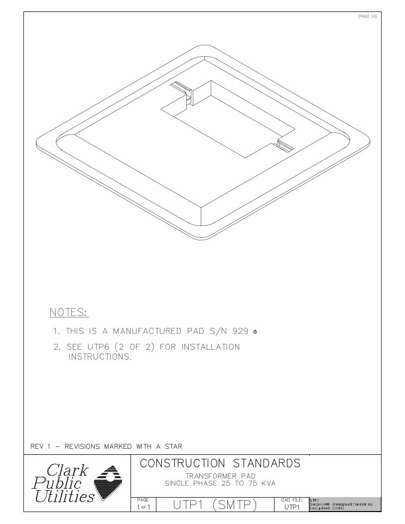
Single-Phase Transformer Set 13
Secondary Pedestal 36
Lighting 42
Metering 45
Three-Phase Transformer Set 55
Padmount Transformers 60
Single-Phase J-Box 62
Three-Phase J-Box 64
(PAGE 2)
(PAGE 3)

(PAGE 4)

(PAGE 5)

(PAGE 6)

(PAGE 7)

(PAGE 8)

(PAGE 9)
(PAGE 10)
(PAGE 11)

(PAGE 12)

(PAGE 13)
(PAGE 14)

(PAGE 15)

(PAGE 16)

(PAGE 17)
(PAGE 18)

(PAGE 19)

(PAGE 20)

(PAGE 21)

(PAGE 22)

(PAGE 23)

(PAGE 24)

(PAGE 25)

(PAGE 26)

(PAGE 27)
(PAGE 28)
(PAGE 29)
Clark Public Utilities — Commercial Electric Service Handbook
Chapter 3: Commercial Underground Services / January 2011 � 17
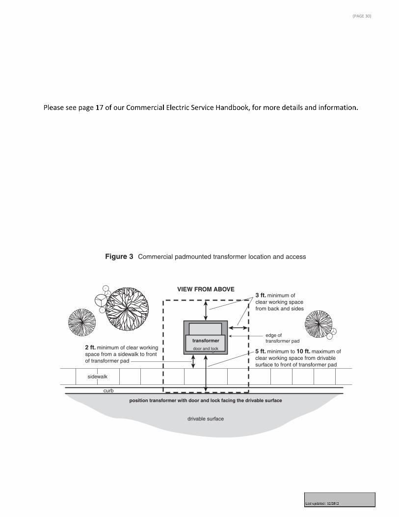
Transformer location and access
Underground electrical facilities must be readily accessible by the utility duringconstruction and for future operation and maintenance. The area around padmounted electrical equipment must provide a clear and level working spaceand remain free from obstructions such as landscaping, poles, retaining walls,structures, fences, etc.
All transformers and padmounted equipment are to be located:
� Within 10 feet of a drivable surface but not closer than 5 feet (Figure 3).
� With the front of the equipment (door and lock side) facing toward the drivablesurface.
� With the transformer pad parallel to the edge of the drivable surface.
� Allowing 10 feet of clearance in front and 3 feet from the back and sides of theequipment (Figure 3).
� At least 2 feet from a sidewalk for pedestrian safety.
Figure 3 Commercial padmounted transformer location and access
drivable surface
VIEW FROM ABOVE
curb
transformer
3 ft. minimum of clear working spacefrom back and sides
5 ft. minimum to 10 ft. maximum of clear working space from drivable surface to front of transformer pad
edge of transformer pad
position transformer with door and lock facing the drivable surface
2 ft. minimum of clear working space from a sidewalk to front of transformer pad
sidewalk
door and lock
(PAGE 30)
Clark Public Utilities — Commercial Electric Service Handbook
18 � Chapter 3: Commercial Underground Services / January 2011
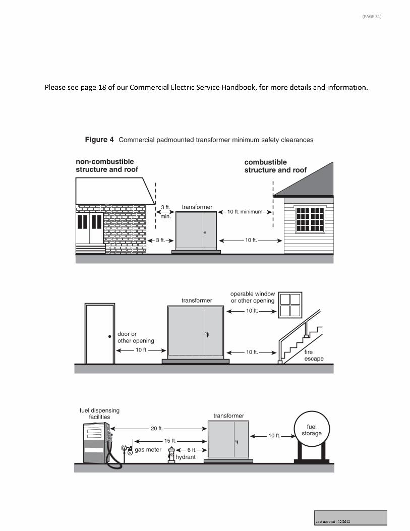
Transformer safety clearances
Clearances from padmounted transformers to structures are measured from the nearest metal portion of the transformer to the structure or any overhang. The clearance from a building is 10 feet if the building has combustible walls, and 3 feet if the building has non-combustible walls as shown in Figure 4. Table 4 provides additional safety clearances that apply to any oil-filled electricalequipment.
non-combustiblestructure and roof
combustiblestructure and roof
20 ft.
10 ft.
10 ft. minimum
operable windowor other opening
door or other opening
gas meter
transformer
transformer
transformer
hydrant
fuel dispensingfacilities
fireescape
10 ft.
10 ft.
10 ft.
10 ft.15 ft.
6 ft.
fuelstorage
3 ft.
min.
3 ft.
Figure 4 Commercial padmounted transformer minimum safety clearances
(PAGE 31)

Clark Public Utilities — Commercial Electric Service Handbook
20 � Chapter 3: Commercial Underground Services / January 2011
� If the distance between the corner posts exceeds 5 feet, a removable center post is required (Figure 5).
� If a removable center post is installed, the threaded joint requires treatment with an anti-seizing agent.
� Paint exposed section of post “traffic yellow.”
Figure 5 Guard post (bollard) installation for commercial transformers
FRONT VIEW
VIEW FROM ABOVE
3 ft.minimum
18 in.minimum
on 45°
removable center post,as required
2 ft.
domed concrete
FINAL GRADE
4 in. galvanized/steel pipe,
concrete filled
4 in. galvanized/steel pipe,
concrete filled
concrete fill
removable center post,as required
coupling
do not fillcenter post
with concrete
edge of transformer pad
commercial transformer
door and lock
edge of transformer
NOTE: Additional guard posts may be required at back and sides of transformer.
(PAGE 32)

(PAGE 33)

(PAGE 34)

(PAGE 35)

(PAGE 36)

(PAGE 37)
(PAGE 38)
(PAGE 39)

Clark Public Utilities — Residential Electric Service Handbook
Chapter 3: Underground Secondary Services / February 2010 � 17
FRONT OF
TRANSFORMER####
use the utility providedwhite paint mark to position trench
(or use transformer lock if mark is not shown)
leave 8 ft. tail of triplexwire at transformer
NOTE: Clark Public Utilitiespersonnel will route wireinto energized facilities.
NOTE: Clark Public Utilitiespersonnel will route wireinto energized facilities.
2 ft.
secondary trench to secondary pedestal
secondarytrench topadmounttransformer
conduit aimed atcenter of pedestal
(leave 2 feet between end of conduit and pedestal)
transformer lock
transformer number
bushing required,do not permanently
attach to conduit
24 in.trench depth
18 in. minimum coverto top of conduit
8 ft. of makeup wire
2 ft.
6 in.
view from side
view from back
2 ft. to 2-1/2 ft. open
Figure 7 Typical secondary trenches to underground utility sources
(PAGE 40)

Clark Public Utilities — Residential Electric Service Handbook
Chapter 3: Underground Secondary Services / February 2010 � 13
CHAPTER3Underground Secondary Services
Preparing for the installation
Typically, an extension of secondary 120/240 volt electrical service is all that isrequired if less than 200 feet of secondary voltage wire is needed to connect the meter socket to a transformer. For homes with large motor loads such as multiple heat pumps or dryers, air conditioning units, etc., this distance may beless. All single-family residences not located within 200 feet of existing primaryrequire an underground primary line extension to place a transformer closer to the structure. See Chapter 4, Primary Line Extensions, for more information onthis type of installation.
The following checklist will assist in preparing a project for the installation of secondary underground electric service. After these items have been completed,Clark Public Utilities will connect the service and set the meter (Figure 4).
dig out and expose back of
pedestal
conduit aimed atcenter of pedestal
bushing required,do not permanently
attach to conduit
24 in. radius,2 in. schedule 40,90 degree elbow
3 in. schedule 40 PVC
2 in.schedule
80 PVC
meter base(ground per NEC)
24 in.trench depth
8 ft. ofmakeup wire
secondarypedestal
6 ft. maximum5 ft. preferred5 ft. minimum
serviceentranceequipment
18 in. minimumicover to topiof conduit
2 ft. to 2-1/2 ft. open
6 in.
3 in. to 2 in.schedule 40reducer
Figure 4 Typical underground secondary service
(PAGE 41)

(PAGE 42)

(PAGE 43)

(PAGE 44)
70'
70'
100'
140'
400'
200'
160'
200'
300'
150'#10 WIRE @ .009989 OHM PER 10'
75'
80'
100'
60'
200'
0.5374
0.3386
0.418
0.4974
0.458
0.4206
0.1808
0.2108
0.2208
0.2608
0.461
0.1708
0.1408
0.1808
0.2208
0.243
120'
250'
0.002
0.3786
0.17216
0.2198
0.28332
0.009
0.05
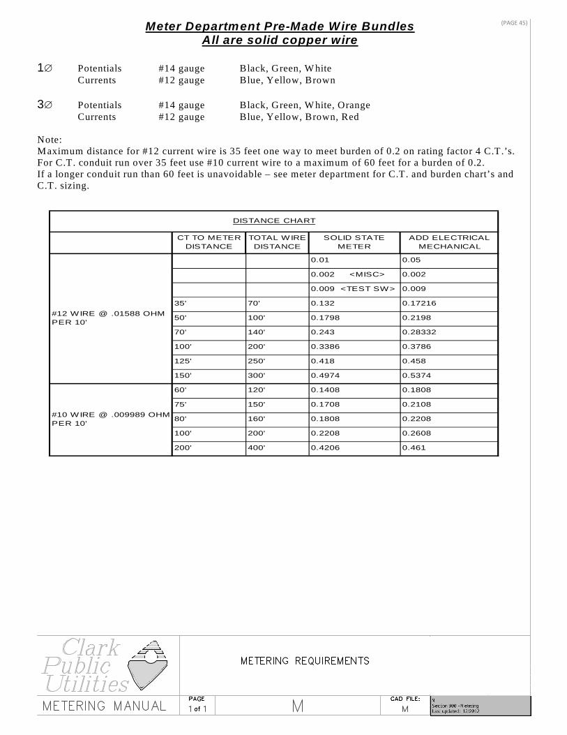
DISTANCE CHART
SOLID STATE METER
TOTAL WIRE DISTANCE
#12 WIRE @ .01588 OHM PER 10'
0.002 <MISC>
ADD ELECTRICAL MECHANICAL
150'
0.009 <TEST SW>
0.132
0.1798
100'
125'
35'
50'
0.01
CT TO METER DISTANCE
Meter Department Pre-Made Wire Bundles All are solid copper wire
1∅ Potentials #14 gauge Black, Green, W hite Currents #12 gauge Blue, Yellow, Brown 3∅ Potentials #14 gauge Black, Green, W hite, Orange Currents #12 gauge Blue, Yellow, Brown, Red Note: Maximum distance for #12 current wire is 35 feet one way to meet burden of 0.2 on rating factor 4 C.T.’s. For C.T. conduit run over 35 feet use #10 current wire to a maximum of 60 feet for a burden of 0.2. If a longer conduit run than 60 feet is unavoidable – see meter department for C.T. and burden chart’s and C.T. sizing.
(PAGE 45)

(PAGE 46)

(PAGE 47)

Clark Public Utilities Metering RequirementsCommercial Applications
Circle AW part numbers are for cross reference only. All Commercial current transformer cabinets shall have hinged doors.
CURRENT TRANSFORMER CABINET DIMENSIONS, CT MOUNTING BASE
See EUSERC Spec – 328B & 329B Over 800 Amps Switchgear Required Maximum wire size 600 MCM per lug or parallel per EUSERC SPEC. & UL label Rev 4: Changed blocks with a *.
Source Voltage
Ampacity Reference Circle AW Part Number
Meter Diagram Numbers
Number of Terminals
Bypass Provision Required
Test Switch Required
120 Volts 1∅ 2 Wire
0-100 Amps
U121314* MD01 4 Yes No
120/240Volt 1∅ 3Wire
0-200 Amps
U264 MD02 4 Yes No
120/240Volt 1∅ 3Wire
0-400 Amps
324N, 324NF
MD03 4 Yes No
120/240Volt 1∅ 3Wire
Over 200 Amps
12146 MD10 MD11
6 No Yes
240/480Volt 1∅ 3Wire
0-200 Amps
124TB MD02 MD05 Dmd
4 Yes No
240/480Volt 1∅ 3Wire
Over 200 Amps
12146 MD10 MD11
6 No Yes
120/208Volt 3Wire Network
0-200 Amps
125TB MD04 5 Yes No
120/208Volt 3Wire Network
Over 200 Amps
12148 MD12 8 No Yes
240Volt 3∅ 3Wire Delta
0-200 Amps
125TB MD06 5 Yes No
120/208Volt 3∅ 4Wire Wye
0-200 Amps
127TB MD07 7 Yes No
120/208Volt 3∅ 4Wire Wye
Over 200 Amps
121413 MD13 13 No Yes
240/120Volt 3∅ 4Wire Delta
0-200 Amps
127TB MD08 7 Yes No
240/120Volt 3∅ 4Wire Delta
Over 200 Amps
121413 MD14 13 No Yes
277/480Volt 3∅ 4Wire Wye
0-200 Amps
127TB MD07 7 Yes No
277/480Volt 3∅ 4Wire Wye
Over 200 Amps
121413 MD13 13 No Yes
480Volt 3∅ 3Wire Delta
0-200 Amps
125TB MD06 5 Yes No
480Volt 3∅ 3Wire Delta
Over 200 Amps
12148 MD12 8 No Yes
Amperes Dimensions Circle AW or Equivalent 200 Amps- 400 Amps 1∅ 24” X 30” X 11” 6019-HAL (LUG LUG) 401 Amps- 800 Amps 1∅ 30” X 36” X 11” 6019-HEL (LUG LUG) 200 Amps- 400 Amps 3∅ 30” X 36” X 11” 6019-HAL or 6067-HAL 401 Amps- 800 Amps 3∅ 36” X 48” X 11” 6019-HEL or 6067-HEEL
(PAGE 48)

Clark Public Utilities Metering Requirements Residential Applications
Circle AW part numbers are for cross reference only.
CURRENT TRANSFORMER CABINET DIMENSIONS, CT MOUNTING BASE
* Optional Notes: 1. CT Metering for 200- 400 Amp panels required pre-approval from Clark Public Utilities 2. All CT cans shall be mounted outside. Rev 2: Add optional CT cabinet dimensions and notes.
Source Voltage
Ampacity Reference Circle AW Part Number
Meter Diagram Numbers
Number of Terminals
Bypass Provision Required
Test Switch Required
120 Volts 1∅ 2 Wire
0-100 Amps
011 MD01 4 No No
120/240Volt 1∅ 3Wire
0-200 Amps
204, U204 MD02 4 No No
120/240Volt 1∅ 3Wire
0-400 Amps
324N, 324NF
MD03 4 Yes No
120/240Volt 1∅ 3Wire
Over 400 Amps
UO11, 011, 925 or 926
MD09 MD11A
5 or 6 No No
Amperes Dimensions Circle AW or Equivalent 200 Amps- 400 Amps 1∅ Window 24”h X 32”w X 9”d PED *401 Amps- 800 Amps 1∅ Buss Mt. 24”h X 30”w X 11”d hinged door 6019-HAL (LUG LUG) 200 Amps- 400 Amps 3∅ Window 30”h X 36”w X 11”d PED *401 Amps- 800 Amps 3∅ Buss Mt. 36”h X 48”w X 11”d hinged door 6019-HEL (LUG-LUG)
(PAGE 49)
Clark Public Utilities — Commercial Electric Service Handbook
Chapter 4: Commercial Metering / January 2011 � 33
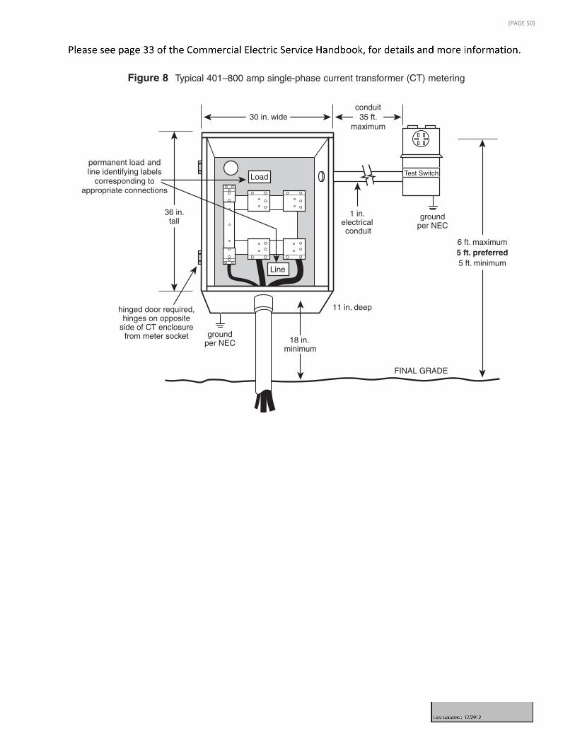
1 in. electrical conduit
FINAL GRADE
6 ft. maximum5 ft. preferred5 ft. minimum
30 in. wideconduit35 ft.
maximum
11 in. deep
36 in.tall
18 in. minimum
hinged door required,hinges on opposite
side of CT enclosurefrom meter socket
permanent load andline identifying labels
corresponding toappropriate connections
groundper NEC
groundper NEC
Load
Line
Test Switch
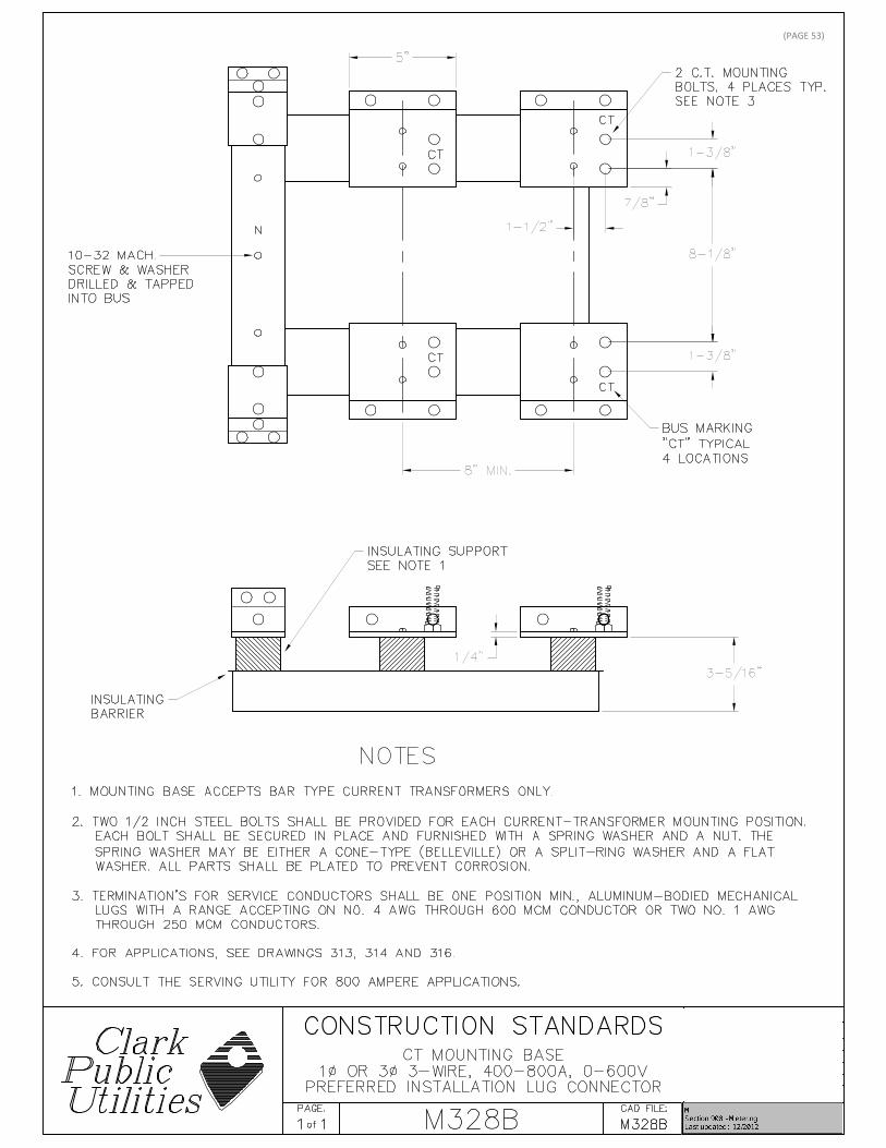
CT mounting base
Installation requirements for current transformer mounting bases are as follows(Figure 9):
� Mounting base is rated for a minimum of 50k amps fault current.
� Line and load side terminations require two bolts per connector and two bolts on the neutral bus.
� The customer furnishes all lugs and terminates both load and line side conductors to the bus.
� A 4-wire delta service requires orange marking of the high leg.
Switchboard metering
Switchboard metering is required for three-phase services over 800 amps. At the customer’s option, this type of metering may be installed for services sized 201 to 800 amps. The customer-installed equipment must be EUSERC-approved.
Figure 8 Typical 401–800 amp single-phase current transformer (CT) metering
(PAGE 50)

Clark Public Utilities — Commercial Electric Service Handbook
34 � Chapter 4: Commercial Metering / January 2011
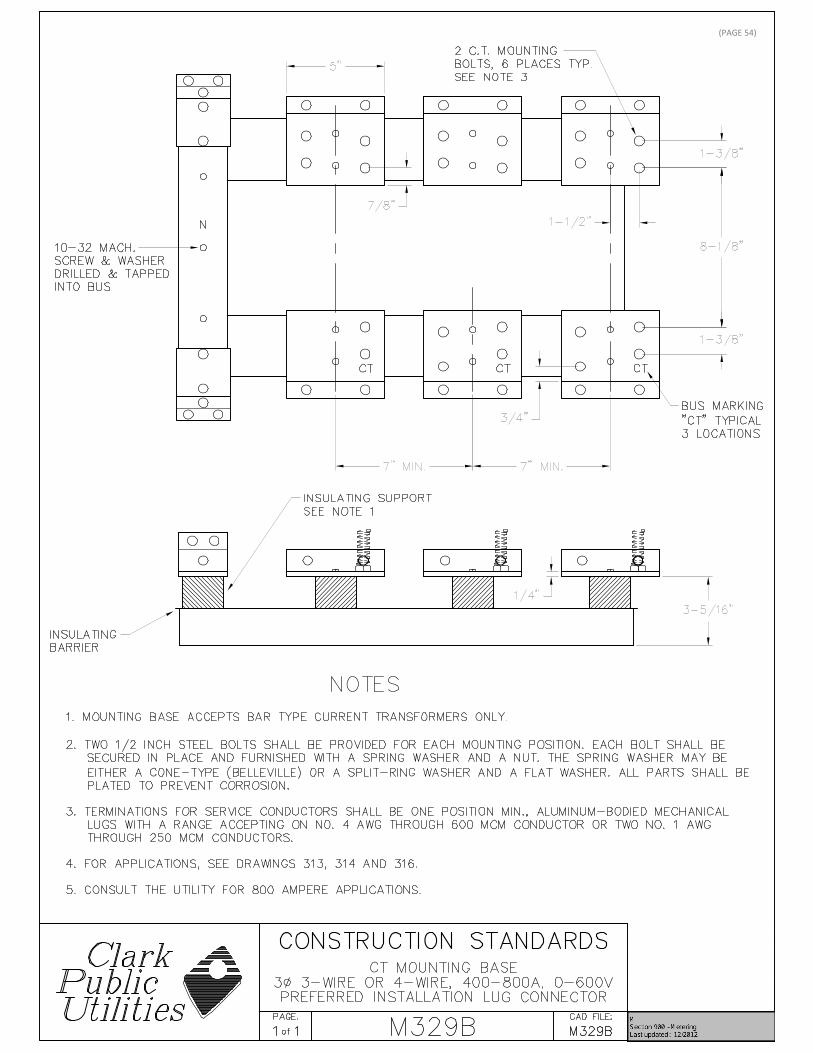
N
CT
7 in. minimum 7 in. minimum
two CT mounting bolts,6 places typical
bus marking “CT”typical 3 locations
10–32 machinescrew and washerdrilled and tapped
into bus
insulating support
insulating barrier
5 in. minimum
1-1/2 in.
7/8 in.
3/4 in.
1-3/8 in.
1-3/8 in.
1/4 in.
8-1/8 in.
3-5/16 in.
CTCT
All customer-installed switchboards require a:
� Current transformer (CT) mounting base.
� Service section.
� Set of bus bars/links.
� Panel(s).
� Meter base with provisions for a test switch.
� Means for locking the meter enclosure with independent 24-hour access to utility personnel.
� Concrete mounting pad.
� Case ground as required per the NEC.
NOTE: Customers requiring more than 480 volts of service will have primarymetering. Ownership and maintenance agreements for primary metered serviceswill be mutually agreed upon with Clark Public Utilities.
Figure 9 Commercial three-phase CT mounting base
NOTE: For additional information see EUSERC drawing 329B.
(PAGE 51)
Chapter 4: Commercial Metering / January 2011 � 35
Clark Public Utilities — Commercial Electric Service Handbook
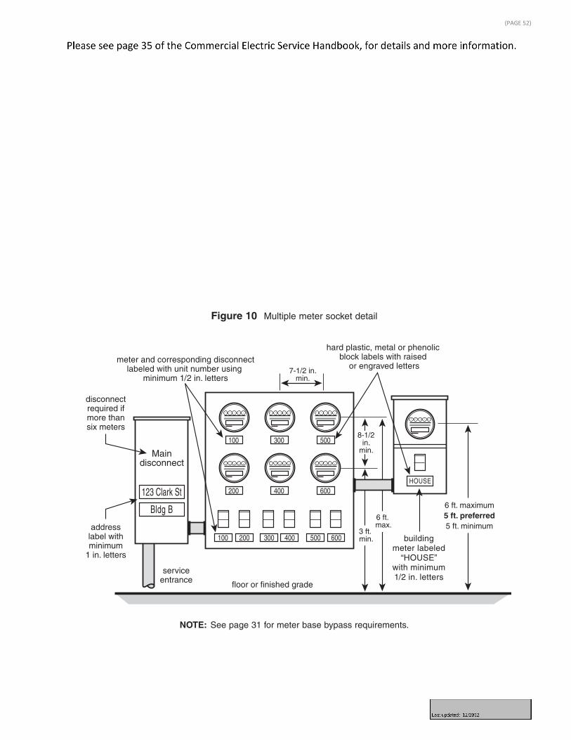
Multiple metered services
Commercial tenant spaces
Non-residential multiple meter installations such as ganged, modular and switch-board metering have the following requirements:
� Spacing to socket centers a minimum of 3 feet and a maximum of 6 feet abovethe finished grade or the floor of an approved equipment room (factory-builtmeter packs require meters installed at least 3 feet above the ground).
� Meter packs with more than six meters require a main disconnect per the NEC(Figure 10).
� All self-contained meter bases require a safety socket or a manual link bypass.
� Each metered service is permanently labeled. (See Multiple meter labeling section for additional information.)
� Panel covers must be secured prior to connection of the service.
Figure 10 Multiple meter socket detail
Maindisconnect
serviceentrance
disconnectrequired ifmore thansix meters
addresslabel withminimum
1 in. letters
floor or finished grade
3 ft. min.
6 ft. max.
8-1/2in.
min.
7-1/2 in.min.
6 ft. maximum5 ft. preferred5 ft. minimum
hard plastic, metal or phenolic block labels with raised
or engraved lettersmeter and corresponding disconnect
labeled with unit number using minimum 1/2 in. letters
buildingmeter labeled
“HOUSE”with minimum1/2 in. letters
Bldg B
123 Clark St
100
100
200
200 300 400 500 600
300
400
500
600HOUSE
NOTE: See page 31 for meter base bypass requirements.
(PAGE 52)
(PAGE 53)
(PAGE 54)

(PAGE 55)

(PAGE 56)

(PAGE 57)

(PAGE 58)

(PAGE 59)

(PAGE 60)
(PAGE 61)

(PAGE 62)
(PAGE 63)

(PAGE 64)

(PAGE 65)

(PAGE 66)