application of reagents to low permeability and fractured
TRANSCRIPT

Application of Reagents to Low Permeability and Fractured Media –Lessons Learned, Specific Challenges and Best Practices
Josephine Molin, Brant Smith, and Fayaz LakhwalaPeroxyChem Environmental Solutions
Fourth International Symposium on Bioremediation and Sustainable Environmental Technologies (Miami, Florida | May 22-25, 2017)
2
Introducing the Challenge
• Successful In Situ Remediation requires:
• Sufficient dose rate based on geochemistry and COC mass
• Contact between reagents and COCs
• Contact could occur directly upon product placement or occur over time via diffusion of substrates and/or contaminants
• Important to understand distribution of impacts, groundwater pathways and tailor remedial approach accordingly
3
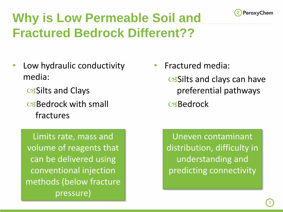
Why is Low Permeable Soil and
Fractured Bedrock Different??
• Fractured media:
Silts and clays can have preferential pathways
Bedrock
Limits rate, mass and volume of reagents that can be delivered using conventional injection
methods (below fracture pressure)
Uneven contaminant distribution, difficulty in
understanding and predicting connectivity
• Low hydraulic conductivity media:
Silts and Clays
Bedrock with small fractures

4
• Primary and secondary porosity
• Hydraulic conductivity primarily a function of fracture numbers and sizes (secondary porosity)
• Primary porosity ranges with type of rock
Fractured Bedrock
Soil Type Total Porosity (%)
Fractured basalt 5 to 50
Karst limestone 5 to 50
Sandstone 5 to 30
Limestone, dolomite 0 to 20
Shale 0 to 10
Fractured crystalline
rock
0 to 10
Dense crystalline
rock
0 to 5
(Freeze and Cherry, 1979)
Porosity in Fractured Bedrock
Rocks
• How much of the bedrock is contaminated?
‣ Crystalline rock—fracture surface only
‣ Porous rock—varies

Key Reagent Properties

6
Key Reagent Properties
The chemistry is usually well understood, the challenge is to achieve contact:
• Injection and distribution properties:
• Liquid vs granular reagents dictates injection methods, transport and diffusion properties
• Longevity:
• Will also impact transport and diffusion
• The shorter lived the substrate, the more critical to achieve direct contact upon installation
Granular EHC powder –composed of microZVIand solid plant fibers
Liquid Emulsified Lecithin

7
Key Reagent PropertiesInjection Properties
Distribution Properties (Solubility)
TypicalLongevity
Treats
FentonsReagent
Liquid Miscible Hours to days Wide range of COCs
Activated Na-Persulfate
Liquid Soluble(>500 g/L)
Weeks to Months
Wide range of COCs
Activated K-Persulfate
Granular Dissolves slowly(45 g/L)
Months or more
Wide range of COCs
Permeox Ultra (CaO2)
Granular Releases O2
upon decomposition
9-12 months Petroleum hydrocarbons
Emulsified Lecithin Substrate (ELS)
Liquid Partially transports, partially adheres
2-3 years CVOCs
Micro-scale ZVI (EHC)
Granular Non soluble 5-10 years Halogenatedcompounds
LONGEVITY
ISCO
BIO
ISCR
Estimating Reagent Dosing
Requirements
9
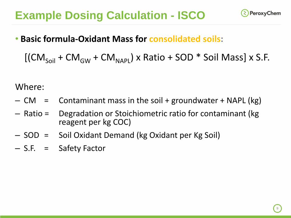
• Basic formula-Oxidant Mass for consolidated soils:
[(CMSoil + CMGW + CMNAPL) x Ratio + SOD * Soil Mass] x S.F.
Where:
– CM = Contaminant mass in the soil + groundwater + NAPL (kg)
– Ratio = Degradation or Stoichiometric ratio for contaminant (kg reagent per kg COC)
– SOD = Soil Oxidant Demand (kg Oxidant per Kg Soil)
– S.F. = Safety Factor
Example Dosing Calculation - ISCO
10
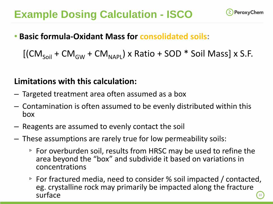
• Basic formula-Oxidant Mass for consolidated soils:
[(CMSoil + CMGW + CMNAPL) x Ratio + SOD * Soil Mass] x S.F.
Limitations with this calculation:
– Targeted treatment area often assumed as a box
– Contamination is often assumed to be evenly distributed within this box
– Reagents are assumed to evenly contact the soil
– These assumptions are rarely true for low permeability soils:
▹ For overburden soil, results from HRSC may be used to refine the area beyond the “box” and subdivide it based on variations in concentrations
▹ For fractured media, need to consider % soil impacted / contacted, eg. crystalline rock may primarily be impacted along the fracture surface
Example Dosing Calculation - ISCO

11
• Basic formula-Oxidant Mass for Fractured Media:
[CM x Ratio + SOD * Soil Mass * %Contact] x S.F.
Where:
– CM = Contaminant mass in soil + groundwater + NAPL calculated over % soil impacted / contacted (kg)
– Ratio = Degradation or Stoichiometric ratio for contaminant (kg reagent per kg COC)
– SOD = Soil Oxidant Demand (kg Oxidant per Kg Soil)
– %Contact = % of soil contacted by oxidant application
– S.F. = Safety Factor
Note: if impacts extend beyond the soil contacted, more than one application round may be needed to achieve the goals.
Modification for Fractured Media

Application Methods and
Case Studies
-Examples of applications to
clay / fractured bedrock sites

13
Application Methods
Low Conductivity Media Fractured Media
Silts and Clays
Bedrock with small fractures
Fractured Silts and
Clays
Fractured Bedrock
Low pressure injections (liquidsubstrates only)
Limited Limited
Yes, but limited
injection volumes
Yes, but limited
injection volumes
High pressure injection (fracturing)
Yes Yes Yes Yes
Soil mixing Yes No Yes No

Low Pressure Injection of
Liquid Substrates
15
Low Pressure Injection into
Fractured Media
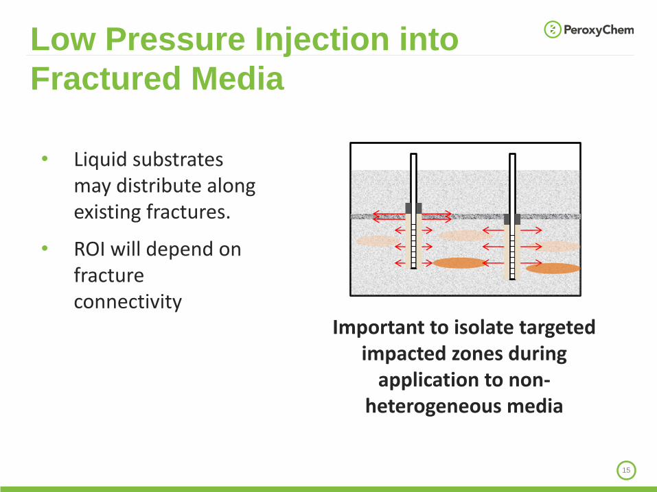
• Liquid substrates may distribute along existing fractures.
• ROI will depend on fracture connectivity
Important to isolate targeted impacted zones during
application to non-heterogeneous media
16
Infiltration system
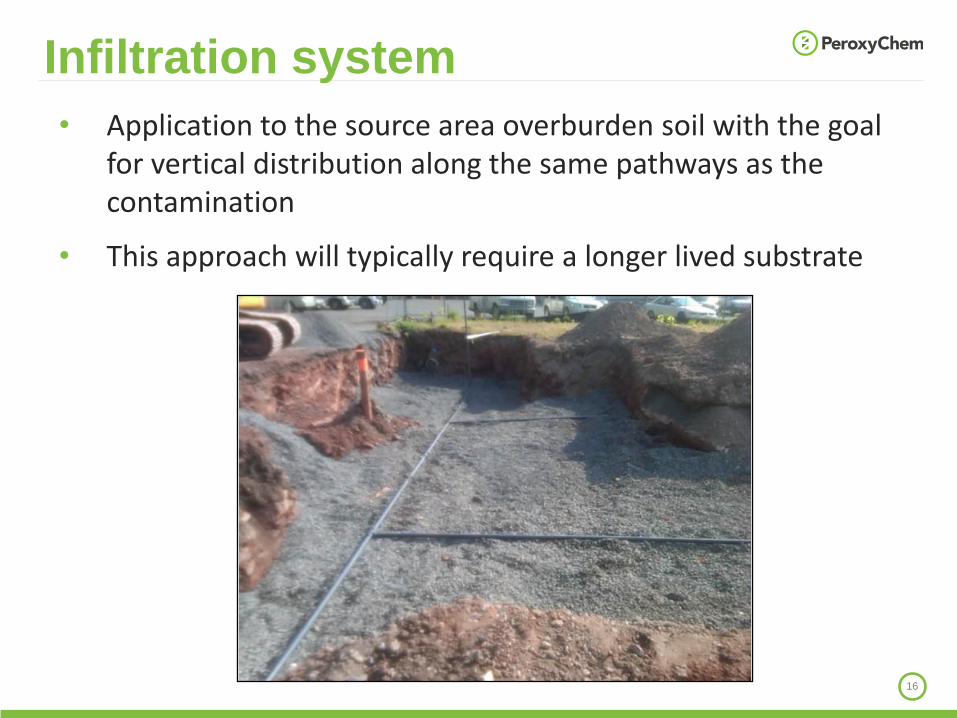
• Application to the source area overburden soil with the goal for vertical distribution along the same pathways as the contamination
• This approach will typically require a longer lived substrate
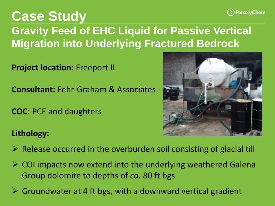
Case StudyGravity Feed of EHC Liquid for Passive Vertical
Migration into Underlying Fractured Bedrock
Project location: Freeport IL
Consultant: Fehr-Graham & Associates
COC: PCE and daughters
Lithology:
➢ Release occurred in the overburden soil consisting of glacial till
➢ COI impacts now extend into the underlying weathered Galena Group dolomite to depths of ca. 80 ft bgs
➢ Groundwater at 4 ft bgs, with a downward vertical gradient
18
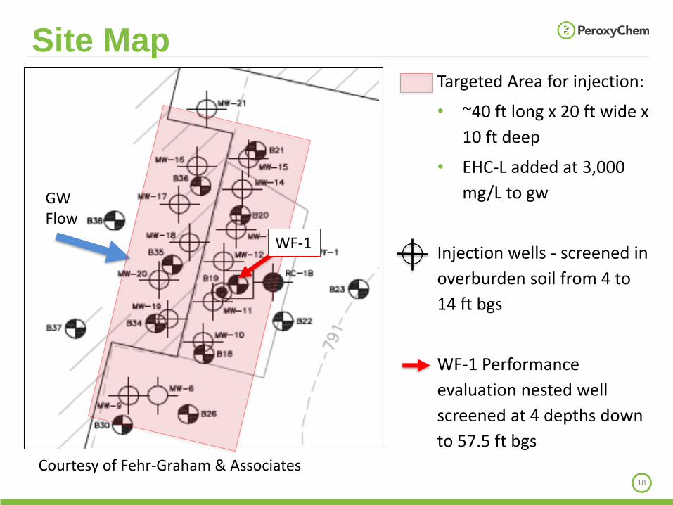
Site Map
GW Flow
Targeted Area for injection:
• ~40 ft long x 20 ft wide x
10 ft deep
• EHC-L added at 3,000
mg/L to gw
Injection wells - screened in
overburden soil from 4 to
14 ft bgs
WF-1 Performance
evaluation nested well
screened at 4 depths down
to 57.5 ft bgs
WF-1
Courtesy of Fehr-Graham & Associates

19
Date Measured
ORP (mV)
Total Iron (mg/L)
TOC (mg/L)
WF-1-1
(15-17.5 ft bgs)
Baseline -99 3.78 1.70
Day 13 -208 93.0 605
WF-1-2
(30-31.5 ft bgs)
Baseline -102 1.70 1.68
Day 13 -204 89.7 655
WF-1-3
(39.5-40.5 ft bgs)
Baseline 102 0.697 <1.00
Day 13 -121 4.13 94.8
WF-1-4
(55-57.5 ft bgs)
Baseline 49 0.537 <1.00
Day 13 -131 1.66 147
Vertical Distribution of EHC-L

High Pressure Injection

21
Injection via fracturing
• Hydraulic and pneumatic fracturing may be performed with granular materials to expand and interconnect with existing fracture pathways:
• ROI of ~5 ft typical for high pressure direct push.
• ROI of up to 70 ft observed with more refined facturing methods.
Sand seam emplaced via hydraulic fracturing (courtesy of FRx)
• Fracturing with for example sand could also be performed prior to application of liquid reagents
• Substrates will typically be limited in volume low volume/ high concentration injections recommended.
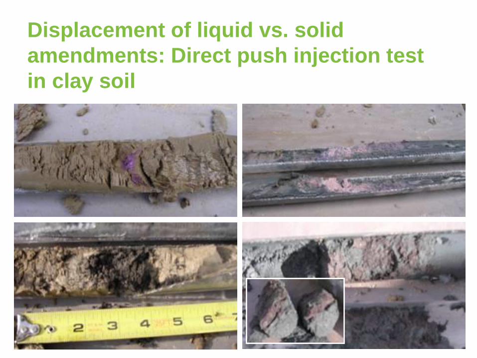
Displacement of liquid vs. solid
amendments: Direct push injection test
in clay soil
23
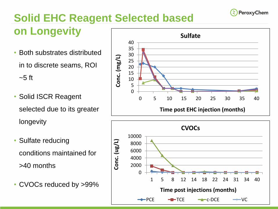
Solid EHC Reagent Selected based
on Longevity
• Both substrates distributed
in to discrete seams, ROI
~5 ft
• Solid ISCR Reagent
selected due to its greater
longevity
• Sulfate reducing
conditions maintained for
>40 months
• CVOCs reduced by >99%
0
2000
4000
6000
8000
10000
1 5 8 12 14 18 22 24 31 34 40
Co
nc.
(u
g/L
)
Time post injections (months)
CVOCs
PCE TCE c-DCE VC
05
10152025303540
0 5 10 15 20 25 30 35 40
Co
nc.
(m
g/L
)
Time post EHC injection (months)
Sulfate
24
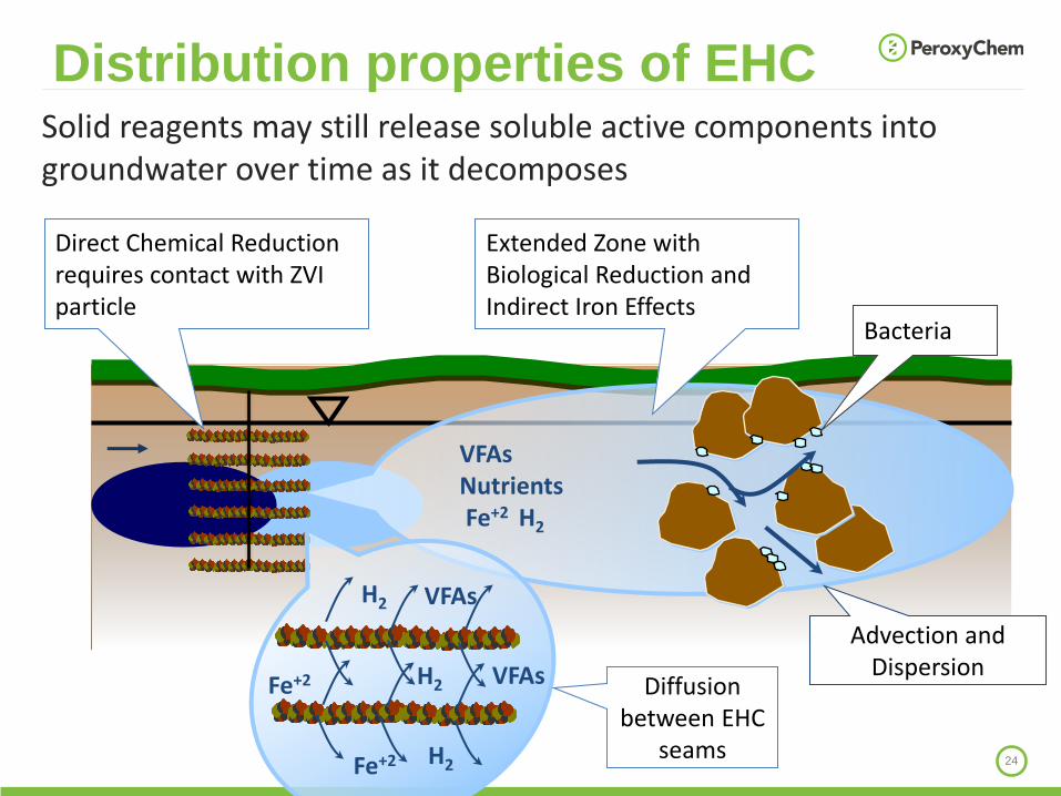
Distribution properties of EHC
Advection and Dispersion
Bacteria
VFAsNutrientsFe+2 H2
Diffusion between EHC
seams
Direct Chemical Reduction requires contact with ZVI particle
Extended Zone with Biological Reduction and Indirect Iron Effects
H2Fe+2
Fe+2 H2
H2
VFAs
VFAs
Solid reagents may still release soluble active components into groundwater over time as it decomposes
Soil Mixing
26
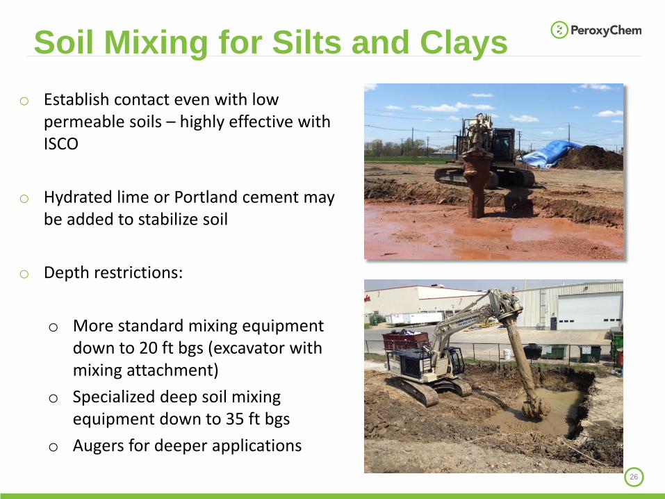
o Establish contact even with low permeable soils – highly effective with ISCO
o Hydrated lime or Portland cement may be added to stabilize soil
o Depth restrictions:
o More standard mixing equipment down to 20 ft bgs (excavator with mixing attachment)
o Specialized deep soil mixing equipment down to 35 ft bgs
o Augers for deeper applications
Soil Mixing for Silts and Clays

Site:
Former Manufacturing Facility WI
TCE Contamination:
Up to 140 mg/Kg
Average: 13.3 mg/Kg
Remedial goal: 1.5 mg/Kg
Lithology:
Clay; vadose zone
Case Study: Application of Alkaline Activated Persulfate via Soil Mixing
Courtesy of ISOTEC
28
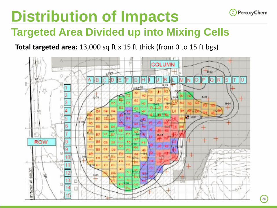
Distribution of ImpactsTargeted Area Divided up into Mixing Cells
Total targeted area: 13,000 sq ft x 15 ft thick (from 0 to 15 ft bgs)

29
Application:
170,000 lbs of Klozurpersulfate distributed according with TCE conc
8 g Klozur persulfate per Kg soil average dose
Case Study: Soil Mixing
Results:
➢ 36 of 37 soil samples below remedial goal
➢ TCE was reduced from an average of 13.3 mg/Kg to 0.084 mg/Kg (>99% reduction)

30
• Successful remediation of low permeability sites requires:
Understanding of distribution of impacts and flow patterns
Tailor application method and reagent to achieve contact
Conclusion / Summary

31
Thank you,
questions are
welcome!
Josephine MolinTechnical Sales ManagerPeroxyChem Environmental Solutions Phone: [email protected]