application of plc device in modeling the electrical
TRANSCRIPT
ISSN 1846-6168 (Print), ISSN 1848-5588 (Online) ID: TG-20160327225416
APPLICATION OF PLC DEVICE IN MODELING THE ELECTRICAL MACHINE DRIVE SEQUENCE
PRIMJENA PLC UREĐAJA ZA MODELIRANJE ELEKTROMOTORNOG POGONA
Igor Petrović, Denis Čamber, Zdravko Petrović
Professional paper
Abstract: In complex industrial processes the simplification of work is ensured using complex automation solutions. In
such systems it is crucial to provide as much automated tasks as possible in order to reduce possibility of human error
and ensure high level of excellence for final product. Complex automation solutions require high level of excellence in
design, production and commissioning. In this paper the use of PLC application for testing single part of automated
system is presented. The results of testing are described in several specific steps recorded during the actual testing. This
will ensure determination of errors without connection of actual electrical machine drive.
Keywords: model, automation, testing, PLC
Stručni članak
Sažetak: Olakšavanje rada u složenim industrijskim procesima osigurava se korištenjem složenih sustava automatizacije.
U takvim sustavima cilj je što više poslova odraditi automatizirano da bi se smanjila mogućnost ljudske pogreške i da bi
se osigurala visoka produktivnost. Složeni sustavi automatizacije zahtijevaju visok stupanj kvalitete u projektiranju, izradi
i puštanju u rad. U ovom radu prikazana je primjena PLC uređaja u ispitivanju jednog dijela automatiziranog sustava.
Rezultati ispitivanja opisani su u nekoliko specifičnih koraka snimljenih tijekom ispitivanja. Na takav način omogućeno
je utvrđivanje pogrešaka bez spajanja konkretnog elektromotornog pogona.
Ključne riječi: model, automatizacija, ispitivanje, PLC
1. INTRODUCTION
When new technology objects are designed, it is
common to implement automation solutions. Most often
designers are trying to cover as much process as possible
for designed object, and therefore automation can become
very complex, as presented in [1]. In order to guaranty
easy use of such systems many parameters must be taken
into consideration, as well as their interdependence. Once
the system is balanced it is easy to use, reliable and safe,
as presented in [2]. But in order to get these characteristics
for the system, it is necessary to maintain high level of
excellence throughout design and construction process.
In this paper a case study of single electrical machine
drive automation testing using PLC is described,
somewhat similar to examples in [3]. The electrical energy
supply and relay systems are tested for its correctness and
functionality. The model used in this case study is
equipped with all input and output data for tested system,
but not with supposed automation programming solution.
The used PLC is programmed so that one can manually
configure any possible scenario, while containing only
physical correspondence between elements. Results are
intended to be considered as functions in logical order. If
any of these functions defer from expected it is obvious
that some errors are present inside the system and further
analytics must be applied to determine them exactly. The
results of this kind of testing can suggest the part of the
system where errors occur.
2. AUTOMATION SYSTEM AND ELECTRICAL MACHINE DRIVE
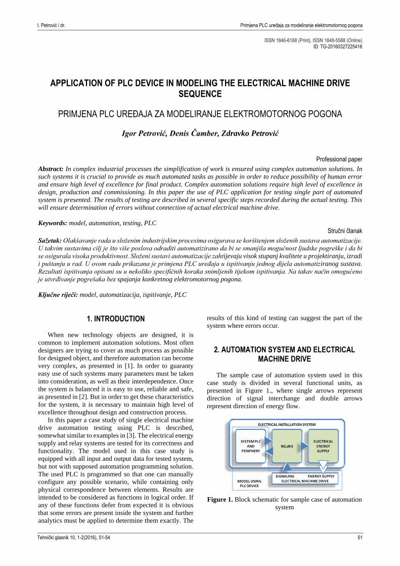
The sample case of automation system used in this
case study is divided in several functional units, as
presented in Figure 1., where single arrows represent
direction of signal interchange and double arrows
represent direction of energy flow.
Figure 1. Block schematic for sample case of automation
system
I. Petrović i dr. Primjena PLC uređaja za modeliranje elektromotornog pogona
Tehnički glasnik 10, 1-2(2016), 51-54 51

The sample case in this study is divided in Electrical
installation system, mainly focused on electrical elements
and wiring, and Electrical machine drive [4], concentrated
on mechanical static and dynamical balance of process.
The Electrical installation system is divided into
functional subsystems:
1. System PLC and periphery
2. Relays
3. Electrical energy supply
All of these subsystems are hardware connected and
they are exchanging information in order for the whole
system to function properly. The Electrical machine drive
is able to select if it is operated from System PLC and
periphery (Remote) or directly from Electrical machine
drive commands (Local), but in each case of operation the
operation loop is gained through Relays and Electrical
energy supply subsystems.
The information exchange is also presented in Figure
1, and it can be seen that information flow is designed as
star configuration, with Relays subsystem as a center of
grid. The Electrical machine drive is supplied with
electrical energy from Electrical energy supply subsystem
using standard Open/Close system and wiring presented in
Figure 2.
Figure 2. Standard Open/Close system and wiring
Considering the motion status of Electrical machine
drive it responds to system through some information
regarding open/close limit switches, open/close torque
gained and thermistor switch. The Relay subsystem is
using this information to operate and protect Electrical
machine drive from over current or similar threats due to
Electrical energy supply. The information is also
forwarded to System PLC and periphery subsystem,
where if Remote operation is selected, the program returns
control signals for Relays to forward to Electrical energy
supply.
Figure 3. Example of Relays installation in sample case
of automation system
Figure 4. Example of Energy supply installation in
sample case of automation system
3. CONFIGURATION OF SIMULATION STATION
In order to gain high level of excellence for this
product one must ensure as good testing as possible before
delivery. Therefore, the testing is done using PLC device
Application of PLC Device in Modeling the Electrical Machine Drive Sequence I. Petrovic et al.
52 Technical Journal 10, 1-2(2016), 51-54

described in [5] (not the one in System PLC and
periphery), named Simulation station, which is equipped
with model of Electrical machine drive and System PLC
and periphery. The model is actually provided through
program integrated in Simulation station.
The Simulation station is planned in one part to match
electrical connection of Electrical machine drive and
System PLC and periphery in other part. The connection
links are made exactly to match connection terminals of
Electrical machine drive and System PLC and periphery,
and model ensures functionality match. The logic of
System PLC and periphery is not the topic of this case
study and is not implemented in model. Also, the model is
equipped with SCADA application for monitor,
measurement and operation control, using software
solution described in [6]. The testing operator is fully able
to monitor all incoming signals from Relays, monitor state
of incoming energy flow from Electrical energy supply,
and also operate all outgoing signals to Relays. Outgoing
signals allow simulation of any scenario available and is
not dependent on most of input signals. The measurement
is not supported in this Electrical machine drive and
therefore is not implemented in subject SCADA.
Figure 5. Simulation station
Figure 6. Offline screenshot of SCADA application
The Simulation station is presented in Figure 5 and
consists of:
1. Power supply
2. PLC device with model program
3. Periphery for PLC device
4. Thermistor output model
5. Connection terminals
The offline SCADA screenshot is presented in Figure
6. Electrical machine drive part of model can be seen on
the left side of the screen. It is equipped with five output
signals from modeled drive, and two input power flows
into modeled drive. Output signals are fully independent
and can be activated at any time. Input signals are
activated from Electrical energy supply and cannot be
operated manually. System PLC and periphery part of
model can be seen on the right side of the screen. It is
equipped with three output signals from modeled PLC,
and four input signals into modeled PLC. Output signals
are partially dependent to inputs, and cannot be activated
if Local operation or Error inputs are active. Input signals
are activated from Relays and cannot be operated
manually. Application is communicating with PLC device
using PC/PPI interface through RS-232 port of computer.
4. TESTING RESULTS USING SIMULATION STATION
Testing results are made online during the actual
testing in the Ipsus electrical workshop on 3rd March 2016.
Testing is s sequentially conducted on 8 separate devices,
using same procedure for simulation scenarios.
Figure 7 is a screenshot in moment (sample 1) when
system is operated Locally to open, already hit open limit
switch and just gained limit torque. In this moment the
system should stop opening operation in Relays and
Electrical energy supply. If opening stops, system works
properly for this scenario. If the action does not stop it
means that system has a fault.
Figure 7. Testing – sample 1
Figure 8 is a screenshot in moment (sample 2) when
system is operated locally and starts to close, and still
hitting open limit switch. Limit torque is not active on
either direction. In this moment system should be in
normal closing operation in Relays and Electrical energy
supply. If closing is operational system works properly for
this scenario. If the action does not stop it means that
system has a fault.
I. Petrović i dr. Primjena PLC uređaja za modeliranje elektromotornog pogona
Tehnički glasnik 10, 1-2(2016), 51-54 53

Figure 8. Testing – sample 2
Figure 9 is a screenshot in moment (sample 3) when
the system is operated exactly like in sample 2, only in
Remote operation. It starts to close, and still hitting open
limit switch. Limit torque is not active on either direction.
In this moment system should be in normal closing
operation in Relays and Electrical energy supply. If
closing is operational, the system works properly for this
scenario. If the action does not stop, it means that the
system has a fault.
Figure 9. Testing – sample 3
Testing results indicated few errors. The exact errors
were detected and changes were applied to gain full
functionality of the tested system.
5. CONCLUSION
This case study presented simple testing improvement
on the example of electrical machine drive with
automation. Once the simulation station is configured and
tested it is easy to use it for testing the electrical
installation. Errors are usually present due to human
factor, but in this way can easily be discovered and
annulated. The upside of this kind of testing is that it
reduces problems during, or even improves,
commissioning.
6. REFERENCES
[1] Bolton, W: Programmable Logic Controllers, Fifth
Edition, USA, Elsevier, 2009.
[2] Bailey, D.: Practical SCADA for Industry, USA,
Elsevier, 2003.
[3] Cetinkunt, S.: Mechatronics with Experiments,
Wiley, 2015
[4] http://www.tri-state-tech.com/auma/sar1_iom.pdf
(available on 02. 02. 2016.)
[5] Siemens Simatic: S7-200 Programmable Controller
System Manual 08/2005, Siemens AG Nurnberg,
2005
[6] Siemens Simatic HMI: WinCC flexible 2008
Compact/Standard/Advanced User's Manual
07/2008, Siemens AG Nurnberg, 2008
Authors` contacts:
Igor Petrović, PhD
Technical College in Bjelovar
Trg Eugena Kvaternika 4, 43 000 Bjelovar
043 / 241 – 201; [email protected]
Denis Čamber, mag.ing.el.techn.inf.
Končar – Inženjering za energetiku i transport d.d.
Poslovna jedinica: Infrastruktura i gradovi
Fallerovo šetalište 22, 10 000 Zagreb
01 / 3655 – 611; [email protected]
Zdravko Petrović, MEE
Ipsus d.o.o. Pitomača
Petra Preradovića 3b, 33 405 Pitomača
033 / 715 – 093; [email protected]
Application of PLC Device in Modeling the Electrical Machine Drive Sequence I. Petrovic et al.
54 Technical Journal 10, 1-2(2016), 51-54