application of piezoelectric transducers in structural health monitoring techniques
TRANSCRIPT

5
Application of Piezoelectric Transducers in Structural Health Monitoring Techniques
Najib Abou Leyla1, Emmanuel Moulin1, Jamal Assaad1,
Farouk Benmeddour1, Sébastien Grondel1 and Youssef Zaatar2
1Department of OAE, IEMN, UMR CNRS 8520, Université de Valenciennes et du Hainaut Cambrésis, Le Mont Houy,
2Applied Physics Laboratory – Lebansese University – Campus, 1France
2Lebanon
1. Introduction
The technological advances of recent years have contributed greatly to the prosperity of the
society. An important element of this prosperity is based on networks of inland, sea, and air
transports. However, security in all transport networks remains a major challenge. More
specifically, many researches in the field of aeronautics were done to increase the reliability
of aircrafts. The themes of NDT (Non Destructive Testing), and more precisely the concept
of SHM (Structural Health Monitoring), have thus emerged.
The SHM is a technical inspection to monitor the integrity of mechanical structures in a
continuous and autonomous way during its use. Sensors used in this technique being fixed
and/or integrated to the structure, it differs from traditional NDT using mobile probes. The
first issue is obviously security; a second important issue is reducing financial costs of
maintenance. Thus, a new technique that increases reliability and decreases costs of
maintenance at the same time seems to be a technological revolution.
Indeed, the traditional inspection methods require planned interventions, and periodic
detention of the aircraft, and in some cases the dismantling of some parts. This entire
procedure is necessary despite the high costs incurred. Added to that financial aspect, the
risk of the occurrence of an unscheduled technical problem between two scheduled
inspections is possible. Such a scenario may lead to the replacement of some parts often
costly, and fortunately in less frequent cases to air disasters.
2. Background work and contributions of the team
Security in aeronautics being a major issue, regular inspections is needed for maintenance.
In fact, these materials are subjected to harsh conditions of operation that may damage
them, and thus affect security. Nowadays, traditional inspections induce long
immobilization of the aircraft and therefore high costs.
www.intechopen.com

Advances in Piezoelectric Transducers
88
A research project aimed at developing a SHM system based on guided elastic waves and applicable to aeronautic structures has been elaborated by our laboratory. We sought to understand the propagation of ultrasonic waves in the structures, their interaction with damage, and the behavior of different type of sensors. This global vision aims at increasing the reliability of the inspections while decreasing maintenance costs. For this purpose, embedding the transducers to the structure seems to be interesting. Indeed, ultrasonic waves present in the material, called Lamb waves, spread over long distances and interact with damages present in the structure. Their damage detection capabilities has been known for a long time [1,2]. By implanting small piezoelectric transducers into the structures, Lamb waves can be emitted and received and it is theoretically possible to monitor a whole given area [3,4].
Over the last 15 years, the team has therefore studied the different axes of the SHM:
Characterization of wave propagation in aeronautic materials
Interaction of ultrasonic waves with damage
The use of different type of sensors
Behavior modeling of transducers
Development of adapted processing tools
The expected benefits of SHM system can thus be summarized in few points:
Optimization of maintenance plans (decrease immobilisation periods and therefore maintenance costs)
Increase security (more frequent inspections in an almost real-time)
Increase the life duration of an aircraft
The theme of SHM started in our team for fifteen years with the researches of Blanquet [5]
and Demol [6]. These works were devoted respectively to the study of the propagation of
the Lamb waves and the development of multi-elements transducers to generate and receive
this type of waves in a material. In the continuity of these researches, E. Moulin has studied
the Lamb wave generation [7, 8, 9] and has developed a technique [10] allowing the
prediction of the Lamb wave field excited in an isotropic plate by a transducer of finite
dimensions. In another work [11], a simple and efficient way of modeling a full Lamb wave
emission and reception system was developed. Other works have treated the question of
Lamb wave emission and/or reception using thin, surface-bonded PZT transducers.
Giurgiutiu [12] has used a “pin force” model to account for the mechanical excitation
provided by the emitter. Then, the response of the plate in terms of Lamb waves excitation
has been derived analytically in a 2D, plane strain situation. Nieuwenhuis et al [13] have
obtained more accurate results by using 2D finite element modeling, which allows a better
representation of the transducer behavior. Lanza di Scalea et al [14] have focused on the
reception of unidirectionally propagating, straight-crested Lamb or Rayleigh waves by a
rectangular transducer.
S. Grondel [15] has optimized the SHM using Lamb waves for aeronautic structures by studying the adapted transducer to generate Lamb waves. Paget [16] has elaborated a technique to detect damage in composite materials. In another work, Duquenne [17] has implemented a hybrid method to generate and receive Lamb waves using a glued-surface transducer in a transient regime. F. El Youbi [18] has developed a sophisticated signal
www.intechopen.com

Application of Piezoelectric Transducers in Structural Health Monitoring Techniques
89
processing technique based on the frequency-time technique and the Fourier transform spatiotemporal to study separately the sensibility of each Lamb mode to damage. More recently F. Benmeddour [19, 20] has studied the interaction of Lamb waves with different type of damage by modelling the diffraction phenomena, and M. Baouahi [21] has considered the 3-D aspect of the Lamb waves generation.
A wide range of work has already been reported on the interaction of Lamb waves with
damage and discontinuities such as holes [22, 23], delaminations [24, 25], vertical cracks [26],
inclined cracks [27], surface defects [28], joints [29, 30] and thickness variations [31]. More
specifically, studies of the interaction with notches have also been carried out. For example,
Alleyne et al. [32, 33], have studied the sensitivity of the A0, S0 and A1 modes to notches. In
this analysis, they have shown the interest of using the two-dimensional Fourier transform
to quantify each scattered Lamb mode. More recently, Lowe et al. [34, 35], have analyzed the
behavior of the A0 mode with notches as a function of the width and the depth. The authors
[36] have then extended this study to the S0 mode.
Finally, E. Moulin [37] studied and validated experimentally the potential of developing a
passive SHM system (without the need on an active source), based on the exploitation of the
natural ambient acoustic sources present in an aeronautic structure during flight. This
technique has been widely exploited in seismology [38, 39, 40], underwater acoustics [41, 42]
and recently ultrasonic [43, 44, 45].
These works contributed to the progress of resolving the different problems related to SHM.
They can be synthesized in four main points:
The modeling of an active complete SHM system (transmission / propagation /
reception), in the absence of damage: Development of an efficient modeling tool that
takes into account the actual characteristics, including 3-D aspect
The modeling and interpretation of diffraction phenomena (transmission, reflection,
mode conversions) on a number of defect types
Development of a sophisticated signal processing technique (time-frequency technique
and spatiotemporal Fourier transform) to minimize the risk of misinterpretation
Demonstration of the feasibility of a passive SHM system based on the exploitation of
natural ambient acoustic fields.
All of this work has enabled the team to acquire the skills needed to develop a SHM system.
The following section is devoted to the presentation of some results for each of the above
points.
3. Modeling and results
3.1 Modeling of emission – reception transient system
The work described in this section is intended to present a simple and efficient way of
modeling a full Lamb-wave emission and reception system. The advantage of this modular
approach is that realistic configurations can be simulated without performing cumbersome
modeling and time-consuming computations. Good agreement is obtained between
predicted and measured signals.
www.intechopen.com
Advances in Piezoelectric Transducers
90
It will be assumed here that the bonded piezoelectric receiver has a small influence on the wave propagation [46]. As a consequence, the displacement imposed at the plate-receiver interface will be considered to be the surface displacement field associated to the incident Lamb waves. The validity of this assumption is realistic if either the transducer is very thin compared to the plate thickness or very small compared to the shortest wavelength [11].
The emission process is modeled using the finite element – normal mode technique described above. It allows predicting the modal amplitudes of each Lamb mode. Then, each Lamb mode is treated separately as a displacement input on the lower surface of the receiving transducer. In summary, the input of the model is the electrical signal (in volts) applied to the emitter and the output is the electrical signal (in volts) received at the receiver. Therefore, the theoretical and measured results can be directly compared to each other, without any adjustment parameters.
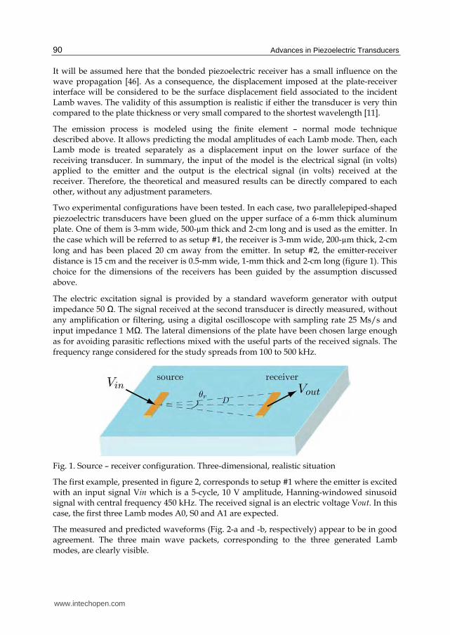
Two experimental configurations have been tested. In each case, two parallelepiped-shaped
piezoelectric transducers have been glued on the upper surface of a 6-mm thick aluminum
plate. One of them is 3-mm wide, 500-µm thick and 2-cm long and is used as the emitter. In
the case which will be referred to as setup #1, the receiver is 3-mm wide, 200-µm thick, 2-cm
long and has been placed 20 cm away from the emitter. In setup #2, the emitter-receiver
distance is 15 cm and the receiver is 0.5-mm wide, 1-mm thick and 2-cm long (figure 1). This
choice for the dimensions of the receivers has been guided by the assumption discussed
above.
The electric excitation signal is provided by a standard waveform generator with output
impedance 50 Ω. The signal received at the second transducer is directly measured, without
any amplification or filtering, using a digital oscilloscope with sampling rate 25 Ms/s and
input impedance 1 MΩ. The lateral dimensions of the plate have been chosen large enough
as for avoiding parasitic reflections mixed with the useful parts of the received signals. The
frequency range considered for the study spreads from 100 to 500 kHz.
Fig. 1. Source – receiver configuration. Three-dimensional, realistic situation
The first example, presented in figure 2, corresponds to setup #1 where the emitter is excited with an input signal Vin which is a 5-cycle, 10 V amplitude, Hanning-windowed sinusoid signal with central frequency 450 kHz. The received signal is an electric voltage Vout. In this case, the first three Lamb modes A0, S0 and A1 are expected.
The measured and predicted waveforms (Fig. 2-a and -b, respectively) appear to be in good agreement. The three main wave packets, corresponding to the three generated Lamb modes, are clearly visible.
www.intechopen.com

Application of Piezoelectric Transducers in Structural Health Monitoring Techniques
91
The second example corresponds to the results obtained for setup #2, with excitation frequency 175 kHz (Fig. 3). Comments very similar as above can be made. Here again, both the absolute amplitudes as well as the global waveforms are correctly predicted.
Fig. 2. Electrical potential at the 3-mm wide, 0.2-mm thick receiver (setup #1), for a 450 kHz excitation.(a) Experimental. (b) Predicted.
Fig. 3. Electrical potential at the 0.5-mm wide, 1-mm thick receiver (setup #2), for a 175 kHz excitation. (a) Experimental. (b) Predicted.
3.2 Fundamental Lamb modes interaction with symmetrical and asymmetrical discontinuities
The aim of the work presented in this section is to predict the propagation of the
fundamental Lamb modes in a structure containing symmetrical [19] and asymmetrical [20]
discontinuities in a simple and a fast way. The key point is to decompose a given damage
www.intechopen.com
Advances in Piezoelectric Transducers
92
into two elementary types; the symmetrical damage with respect to the median plane and
the asymmetrical one in the plate section. The power reflection and transmission coefficients
are computed, using two techniques, the finite element method with the help of the Atila
code, and the average power flow equation. Indeed, the characterization of damage is done
from the average flow of power. It allows determining the power reflection and
transmission coefficients.
To calculate these coefficients, normal and tangential displacements, as well as the stresses throughout the plate thickness are needed. It is experimentally impossible. While the developed method, based on the decomposition of normal modes, allows the calculation of the average power flow from only a normal displacement or a tangential one acquired at the surface of the plate. The advantages of this technique are that the time processing of the data is reduced, and it allows a direct comparison with the experimental measurements.
To validate the numerical results, the following experimental study was carried out. The instrumentation used in the experimental investigation is shown schematically in the fig. 4. A pulse, from the pulse generator (HM 8035), is used to simultaneously trigger the oscilloscope (Le Croy type LT344) and the two arbitrary function generators (HP 33120A) that deliver a tone burst modified by a Hanning window function to the transducers. The central frequency is taken equal to 200 kHz. The incident Lamb wave of a specific mode is launched by means of two identical piezo-ceramic transducers (PZT-27) placed at the opposite sides of the plate edge. The thickness, the width and the length of these transducers are equal to 1, 6 and 50 mm, respectively. The free lateral resonance frequency of these transducers is near to 200 kHz. The generation of the A0 mode is obtained by exciting the two thin piezo-ceramic transducers with anti-phased electrical signals. On the contrary, the in-phased excitation generates the S0 mode. Two conventional Panametrics transducers are placed on the plate surface before and after the notch. Local honey and gel coupling are employed for the emitters and receivers, respectively. All the signals from the sensors are then recorded using a digital oscilloscope and transferred via the GPIB bus to a computer for signal processing. The aluminum plate used in the experimental investigations is considered with thickness (2d) and length (2L) equal to 6 and 500 mm, respectively. The longitudinal velocity (CL), the transverse velocity (CT) and the density ( ) of this plate are
equal to 6422, 3110 m/s and 2695 kg/m3, respectively. The plate is considered lossless. Here, the notch has a variable width equal to w. The plate thickness changes abruptly either from 2d to 2dp or from 2dp to 2d, with d the half thickness of the plate and p takes values from 0 to 1 with a constant increment.
In this work, the fundamental Lamb mode, S0 or A0, is launched from the plate edge. The
generation of the S0 mode is performed by the application, at the left edge of the plate, of
both tangential symmetrical and normal anti-symmetrical displacements, with respect to the
median plane, windowed by Hanning temporal function. Alternatively, the generation of
the A0 mode is obtained by the application of the tangential anti-symmetrical and the
normal symmetrical displacements.
For the symmetrical notches, no mode conversion is observed, which is consistent with the
theoretical symmetry principles. The figure 5 shows the comparison between the reflection
and transmission power coefficients obtained when the A0 and S0 modes are launched. We
can see a good agreement between the experimental and the numerical results.
www.intechopen.com

Application of Piezoelectric Transducers in Structural Health Monitoring Techniques
93
Fig. 4. Experimental device to study the interaction of Lamb modes with (a) asymmetrical discontinuities and (b) symmetrical discontinuities.
Fig. 5. Comparison between numerical and experimental results for the reflection (R) and the transmission (T) coefficients, when the launched Lamb mode A0 (a) or S0 (b) interacts with a symmetrical discontinuity.
For the asymmetrical notches a mode conversion from the incident mode A0 to the
converted mode S0 and inversely is enabled. The curves of figure 6 show a good agreement
between the experimental and the numerical results for the reflection coefficient, for both
incident and converted modes, when the A0 or S0 mode is launched.
3.3 Dual signal processing for damage detection
The identification of Lamb mode amplitude variation as a function of the damage evolution
is still the most difficult step in the process of damage monitoring using embedded Lamb
wave-based systems. The aim of this section is to propose a simple system based on the
generation of two different frequencies in order to better identify Lamb mode amplitude
and to avoid false data interpretation in plates containing a hole of variable diameter. This
www.intechopen.com

Advances in Piezoelectric Transducers
94
Fig. 6. Comparison between numerical and experimental results for the reflection (R) coefficient, when the launched Lamb mode A0 (a) or S0 (b) interacts with an asymmetrical discontinuity.
identification is based on a simple relation between the short-time Fourier transform (STFT) and the two-dimensional Fourier transform (2DFT).
Experimentally, a 3 mm thick aluminum plate with an emitter and a receiver is considered (Figure 7). The emitter consists of two piezoelectric elements with different widths in order to allow the excitation of two different frequency bands. Their sizes were equal to 15 × 3 × 1 mm3 and 15 × 2 × 1 mm3, which correspond to transverse resonance frequencies of 400 kHz and 600 kHz, respectively. The receiver consists of a 32-electrodes piezoelectric transducer with an inter-electrode distance of 2 mm, and 400 μm thick, 15 mm wide and 63 mm long. It was developed especially to increase the received power. The initial distance between the emitter and the sensor was chosen to be 25 cm. The Lamb waves generated by the emitter were received on different electrodes of the sensor. All the signals were then recorded by a digital oscilloscope with a sampling frequency equal to 5 MHz and transferred to a PC where the signal processing, i.e. STFT and 2DFT, could be applied.
Fig. 7. Experimental measurement setup
www.intechopen.com

Application of Piezoelectric Transducers in Structural Health Monitoring Techniques
95
In order to simulate the damage, a hole of variable diameter is introduced at the plate centre, and its diameter was increased from 1 mm to 13 mm.
By computing the amplitudes on the 2DFT and STFT analysis as functions of the diameter of the hole, the sensitivity of Lamb modes can be analyzed. In fact, the application of the dual signal processing approach to the received Lamb wave signals allows us to monitor the damage evolution using the A0 and S0 Lamb mode amplitude variation in two different frequency bands. Moreover, it is shown (figure 8) that for one of the frequencies a false interpretation can be induced when using only one signal processing technique.
It can be noted that both S0 and A0 modes are sensitive to the presence of the hole for both frequencies 400 kHz and 600 kHz, but the interaction of the same mode at different frequencies does not give similar results. At 600 kHz and for both S0 and A0 modes (see figures 8(a) and (b)), the amplitudes of the 2DFT and the STFT drop quasi-continuously according to the hole diameter by keeping close values. Both methods give results in good agreement and demonstrate the validity of their use. In contrast to this, in the case of the
Fig. 8. STFT and 2DFT amplitude variation as a function of the hole diameter. (a) S0 mode at 600 kHz; (b) A0 mode at 600 kHz, (c) S0 mode at 400 kHz; (d) A0 mode at 400 kHz.
www.intechopen.com

Advances in Piezoelectric Transducers
96
S0 mode at 400 kHz (see figure 8(c)) and for a diameter equal to approximately 9 mm, the amplitude of the 2DFT increases whereas the amplitude of the STFT decreases. Although this variation is relatively small, it represents typically a problem of false data interpretation. Simultaneously, in the case of the A0 mode at 400 kHz (see figure 8(d)), the STFT and the 2DFT amplitudes plotted as functions of the hole diameter show that the amplitudes are considerably increased for a hole diameter greater than 9 mm. Again a false data interpretation can be induced concerning the severity of the damage. This change can be related to a resonance phenomenon related to the presence of the hole. A better understanding of this phenomenon requires three-dimensional studies.
These measurements demonstrate the ability to use the STFT and 2DFT at the same time in order to detect damage and to overcome the problem of false data interpretation. In fact, using only one technique and one frequency can not always allow us to get the severity of the damage and consequently to determine the Lamb wave sensitivities to the presence of damage.
Although the results obtained with the STFT are more satisfactory than the 2DFT in this case, they would be more severe in error if the group velocities of the two modes were more similar or if the tested structure was more complex.
3.4 Passive SHM using ambient acoustic field cross-correlation
Recent theoretical and experimental studies have shown the possibility to retrieve the Green function between two points in a structure by cross-correlating the received signals at these points simultaneously, in the presence of a diffuse acoustic field in the medium. The aim of the work presented in this section is to exploit the mechanical vibrations and subsequent elastic wave fields present in an aeronautic structure during the flight. These vibrations being the result of the turbo engines and the aero acoustic phenomena, their random character makes the exploitation complicated. Meanwhile, the non need of an active source in this case, is a very interesting solution from an energy consumption point of view.
In the following, the reproducibility of the cross-correlation function, its potential to detect a defect, and its sensitivity to the source characteristics are studied. In fact, since the measured cross-correlation is used to monitor the integrity of the structure, it has to be reproducible for different measurements done in the same conditions. A second necessary condition to the study is the ability to detect any form of heterogeneity in the structure, using the cross-correlation of the ambient acoustic field. Finally, since the source-position influences the result, it is crucial to avoid misinterpretations by separating changes caused by source motion from those caused by defect appearance.
3.4.1 Reproducibility of the cross-correlation function
To study the applicability of the ambient noise correlation method, experimentation in the laboratory has been set-up in order to verify the reproducibility and the sensitivity of the correlation function to a defect. Thus, an aluminum plate of 2*1 m2-surface and 6mm-thickness has been considered, and two circle PZ27-piezoelectric transducers of 0.5cm-radius and 1mm-thickness have been glued with honey at two positions A and B. To generate the ambient acoustic noise in the plate, an electrical noise generator has been used, and the signal has been emitted using a circle PZ27-piezoelectric transducer of 1cm-radius
www.intechopen.com

Application of Piezoelectric Transducers in Structural Health Monitoring Techniques
97
and 1mm-thickness, placed at a position O. The signals received at A and B have been measured and sent to a computer using a GPIB bus (Figure 9).
Fig. 9. Experimental set-up for studying reproducibility.
(a) (b)
Fig. 10. Cross-correlation function between A and B for the measurement (a) #1 (b) #2.
The cross-correlation between these two signals has then been computed and averaged on N
= 150 acquisitions to increase the signal-to-noise ratio. Finally, in order to better analyze the
signals, a time-frequency representation has been used. Thus, a wavelet-transform of the
measured cross-correlation function has been computed by convolving with a 5-cycle
Hanning-windowed sinusoid of variable central frequency f0. A time-frequency
representation of the cross-correlation function, in the frequency-band [1-6 kHz], is shown at
figure 10. We can see that for two measurements done in the same conditions, the cross-
correlation function is reproducible.
3.4.2 Sensitivity of the cross-co rrelation function to a defect
In this section, the sensitivity of the cross-correlation function to a defect is studied. Thus,
two measurements have been done, one without a defect and the other with a defect
somewhere in the plate (Figure 11). Concerning the modeling of the defect, for repeatability
purpose, an aluminum disk of 1 cm-radius has been glued on the surface of the plate
www.intechopen.com

Advances in Piezoelectric Transducers
98
between the two points A and B. In fact, such a defect introduces local heterogeneity from
an acoustic impedance change point of view.
Fig. 11. Experimental set-up for defect detection.
The comparison of the measurements (Figure 12) with and without a defect shows that the
cross-correlation function is sensitive to the presence of the defect. The sensitivity is more or
less important depending on the frequency range and the position of the defect.
(a) (b)
Fig. 12. Cross-correlation function between A and B (a) without and (b) with a defect.
3.4.3 Influence of the source characteri stics on the cross-correlation function
The reproducibility and the sensitivity to a defect of the cross-correlation function being
verified, this section will deal with the study of the influence of the source position on the
correlation function. To better highlight the influence of the source position on the cross-
correlation function, experimentation with two source positions is done. The images of the
figure 13, for the first source position (figure 13.a) and the second source position (Figure
13.b), show that the cross-correlation function depends strongly on the source position. This
influence of the source position could be misinterpreted as the appearance of a defect. A
solution to this problem is given in the next section.
www.intechopen.com

Application of Piezoelectric Transducers in Structural Health Monitoring Techniques
99
(a) (b)
Fig. 13. Cross-correlation function between A and B (a) for the first and (b) for the second source position.
3.4.4 Practical application of the ambient noise correlation technique to SHM
In an aeronautic application, the sources exploited can be concentrated and with variable characteristics. This represents a major difficulty for the application. Indeed, in this situation, it is difficult to separate the contributions of the characteristics of the medium, from the characteristics of the source, in the measured information. To overcome this problem, we proposed a solution based on using a third transducer, called “reference transducer” and placed far from A and B, to identify the acoustic source characteristics at the instant of measurement by computing the auto-correlation of the received signal, before doing the diagnostic of the structure.
A simple experimentation has been set-up in the laboratory in order to test the applicability of the principle. Three piezoelectric receivers have been glued, at respective locations A, B and C, on an aluminum plate of 2 m × 1 m surface and 6 mm thickness (Fig. 14). The “ambient” acoustic noise is generated using an amplified loudspeaker working in the audible range (up to approximately 8 kHz), placed under the plate and driven by an electrical noise generator. High-pass filtering is applied in order to reject frequencies below 2 kHz. For repeatability purpose, a “removable” defect was used here instead of an actual structural damage: a small aluminum disk of 1 cm radius bonded between A and B.
Fig. 14. Description of the experimental setup
The cross-correlation of 0.5 s-long signals measured at positions A and B, and the auto-correlation at position C have been averaged over 150 acquisitions. In order to emphasize interesting effects, narrowband filtering has been applied by convolving it with an N-cycle Hanning-windowed sinusoid of variable central frequency f0.
www.intechopen.com
Advances in Piezoelectric Transducers
100
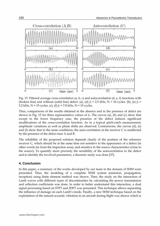
Fig. 15. Filtered average cross-correlation (a, b, c) and autocorrelation (d, e, f) functions with (broken line) and without (solid line) defect. (a), (d) f0 = 2.5 kHz, N = 10 cycles. (b), (e) f0 = 5.2 kHz, N = 15 cycles. (c), (f) f0 = 7.8 kHz, N = 15 cycles.
Thus, comparisons of the results obtained in the absence and in the presence of defect are shown in Fig. 15 for three representative values of f0. The curves (a), (b) and (c) show that except in the lower frequency case, the presence of the defect induces significant modifications of the cross-correlation function. As in a typical pitch-catch measurement, amplitude variations as well as phase shifts are observed. Contrariwise, the curves (d), (e) and (f) show that in the same conditions, the auto-correlation at the receiver C is unaffected by the presence of the defect near A and B.
The reliability of the proposed solution depends clearly of the position of the reference
receiver C, which should be at the same time not sensitive to the appearance of a defect (in
other words far from the inspection area), and sensitive to the source characteristics (close to
the source). To quantify more precisely the sensibility of the autocorrelation to the defect
and to identify the involved parameters, a theoretic study was done [37].
4. Conclusion
In this paper, a summary of the works developed by our team in the domain of SHM were
presented. Thus, the modeling of a complete SHM system (emission, propagation,
reception) using finite element method was shown. Then, the study on the interaction of
Lamb waves with different types of discontinuities by calculating the power transmission
and reflection coefficients was done. In order to better understand this interaction, a dual
signal processing based on STFT and 2DFT was presented. This technique allows separating
the influence of damage on each Lamb’s mode. Finally, a new SHM technique based on the
exploitation of the natural acoustic vibration in an aircraft during flight was shown which is
www.intechopen.com

Application of Piezoelectric Transducers in Structural Health Monitoring Techniques
101
very interesting from an energy consumption point of view. The feasibility of this method
was experimentally validated by proposing a solution that allows separating the
characteristics of the source and those of the medium. Encouraging results make possible
considering the development of autonomous, integrated wireless network sensors for
passive SHM application.
5. References
[1] D. C. Worlton, “Ultrasonics testing with lamb waves”,Nondestruct. Test. 15, 218–222
(1957).
[2] D. N. Alleyne and P. Cawley, “The interaction of lamb waves with defects”, IEEE Trans.
Son. Ultrason. 39, 381–397 (1992).
[3] R. S. C. Monkhouse, P. D. Wilcox, and P. Cawley, “Flexible interdigital pvdf lamb wave
transducers for the development of smart structures”, Rev. Prog. Quant.
Nondestruct. Eval. 16A, 877–884 (1997).
[4] J.-B. Ihn and F.-K. Chang, “Detection and monitoring of hidden fatigue crack growth
using a built-in piezoelectric sensor/actuator network: I.diagnostics”, Smart Mater.
Struct. 13, 609–620 (2004).
[5] P. Blanquet, “Etude de l’endommagement des matériaux composites aéronautiques à
partir de techniques ultrasonores”, PhD Thesis, Report 9724, University of
Valenciennes, France (1997).
[6] T .Demol, “Etude de transducteurs en barettes pour le contrôle santé des structures
aéronautiques composites par ondes de Lamb. Application à la caractérisation de
l’impact basse vitesse”, PhD Thesis, Report 9801, University of Valenciennes,
France (1998).
[7] E. Moulin, J. Assaad, C. Delebarre, H. Kaczmarek and D. Balageas, ‘‘Piezoelectric
transducer embedded in composite plate : Application to Lamb wave generation,’’
J. Appl. Phys. vol. 82, pp 2049-2055 (1997).
[8] E. Moulin, J. Assaad, C. Delebarre et D. Osmont, ‘‘Modelling of Lamb waves
generated by integrated transducers in composite plates, using a coupled Finite
Element - Normal Modes Expansion method,’’ J. Acoust. Soc. Am, vol. 107, pp
87-94 (2000).
[9] E. Moulin, J. Assaad, C. Delebarre et S. Grondel, ‘‘Modeling of integrated Lamb waves
generation systems using a coupled finite element - normal modes expansion
technique,’’ Ultrasonics, vol. 38, pp 522-526 (2000).
[10] E. Moulin, S. Grondel, M. Baouahi, J. Assaad, “Pseudo-3D modeling of a surface-
bonded Lamb wave source”, J. Acoust. Soc. Am., vol. 119, pp 2575-2578, 2006.
[11] E. Moulin, S. Grondel, J. Assaad, L. Duquenne, “Modeling a surface-mounted Lamb
wave emission-reception system : Applications to structural health monitoring”, à
paraître dans J. Acoust. Soc. Am., 2008.
[12] V. Giurgiutiu, “Tuned lamb wave excitation and detection with piezoelectric wafer
active sensors for structural health monitoring”, J. Intell. Mater. Syst. Struct. 16,
291–305 (2005).
www.intechopen.com

Advances in Piezoelectric Transducers
102
[13] J. H. Nieuwenhuis, J. J. Neumann, D. W. Greve, and I. J. Oppenheim, “Generation and
detection of guided waves using pzt wafer transducers”, IEEE Trans. Ultrason.
Ferroelectr. Freq. Control 52, 2103–2111 (2005).
[14] F. L. di Scalea, H. Matt, and I. Bartoli, “The response of rectangular piezoelectric sensors
to raleigh and lamb ultrasonic waves”, J. Acoust. Soc. Am. 121, 175–187 (2007).
[15] Grondel S, Delebarre C, Assaad J, Dupuis J P and Reithler L, “ Fatigue crack monitoring
of riveted aluminium strap joints by Lamb wave analysis and acoustic emission
measurement techniques” NDT&E Int. 25 137–46 (2002)
[16] C Paget, S Grondel, K Levin, C Delebarre, “Damage assessment in composites by Lamb
waves and wavelet coefficients - Smart Materials and Structures” 12, p. 393-402,
2003
[17] L. Duquenne, E. Moulin, J. Assaad, S. Grondel, “Transient modeling of Lamb waves
generated in viscoelastic materials by surface bonded piezoelectric transducers”, J.
Acoust. Soc. Am, vol. 116, pp 133-141, 2004.
[18] El Youbi F, Grondel S and Assaad J. “Signal processing for damage detection using two
different array transducers” Ultrasonics 42 803–6. (2004)
[19] F. Benmeddour, S. Grondel, J. Assaad, E. Moulin, “Study of the fundamental Lamb
modes interaction with symmetrical notches”, NDT\&E Int., vol. 41, pp 1-9,
2007.
[20] F. Benmeddour, S. Grondel, J. Assaad, E. Moulin, “Study of the fundamental Lamb
modes interaction with asymmetrical discontinuities”, NDT\&E Int., vol. 41, pp
330-340, 2008.
[21] M. Baouahi, “Modélisation 3D de la generation des ondes de Lamb par des
transducteurs piézoéléctriques mono et multi-éléments”, PhD Thesis, Report 0711,
University of Valenciennes, France (2007).
[22] Diligent O, Grahn T, Bostro¨m A, Cawley P, Lowe MJS. “The low-frequency reflection
and scattering of the S0 Lamb mode from a circular through-thickness hole in a
plate: finite element, analytical and experimental studies.” J Acoust Soc Am
2002;112(6):2589–601.
[23] Grahn T. “Lamb wave scattering from a circular partly through thickness hole in a
plate.” Wave Motion 2003;37:63–80.
[24] Guo N, Cawley P. “The interaction of Lamb waves with delaminations in composite
laminates.” J Acoust Soc Am 1993; 94(4):2240–6.
[25] Hayashi T, Kawashima K. “Single mode extraction from multiple modes of Lamb wave
and its application to defect detection”. JSME Int J 2003; 46(4):620–6.
[26] Le-Cle´zio E, Castaings M, Hosten B. “The interaction of the S0 Lamb mode with
vertical cracks in an aluminum plate.” Ultrasonics 2002; 40:187–92.
[27] Wang L, Shen J. “Scattering of elastic waves by a crack in a isotropic plate.” Ultrasonics
1997; 35:451–7.
[28] Cho Y, Rose JL.”An elastodynamic hybrid boundary element study for elastic wave
interactions with a surface breaking defect.” Int J Sol Struct 2000; 37:4103–24.
[29] Lowe MJS, Challis RE, Chan CW. “The transmission of Lamb waves across adhesively
bonded lap joints.” J Acoust Soc Amer 2000; 107(3):1333–45.
www.intechopen.com

Application of Piezoelectric Transducers in Structural Health Monitoring Techniques
103
[30] Mal AK, Chang Z, Guo D, Gorman M. Lap-joint inspection using plate waves. In:
Rempt RD, Broz AL (Eds.), SPIE nondestructive evaluation of aging aircraft,
airports, and aerospace hardware, vol. 2945, 1996, p. 128–137.
[31] Cho Y. “Estimation of ultrasonic guided wave mode conversion in a plate with
thickness variation.” IEEE Trans Ultrason Ferroelectr Freq Control 2000;17(3):591–
603.
[32] Alleyne DN, Cawley P.” A 2-dimensional fourier transform method for the quantitative
measurement of Lamb modes.” IEEE Ultrason Symp 1990;1143–6.
[33] Alleyne DN, Cawley P. “The measurement and prediction of Lamb wave interaction
with defects”. IEEE Ultrason Sympos 1991; 855–7.
[34] Lowe MJS, Cawley P, Kao J-Y, Diligent O. “Prediction and measurement of the
reflection of the fundamental anti-symmetric Lamb wave from cracks and notches”.
In: Thompson DO, Chimenti DE, editors. Review of progress in quantitative NDE,
vol. 19A. New york: Plenum; 2000. p. 193–200.
[35] Lowe MJS, Cawley P, Kao J-Y, Diligent O. “The low frequency reflection characteristics
of the fundamental antisymmetric Lamb wave A0 from a rectangular notch in a
plate.” J. Acoust Soc Am 2002; 112(6):2612–22.
[36] Lowe MJS, Diligent O.” Low-frequency reflection characteristics of the S0 Lamb wave
from a rectangular notch in a plate”. J Acoust Soc Am 2002;111(1):64–74.
[37] E. Moulin, N. Abou Leyla, J. Assaad, and S. Grondel, “Applicability of acoustic noise
correlation for structural health monitoring in nondiffuse field conditions”, Appl.
Phys. Lett. 95, 094104 (2009).
[38] N. M. Shapiro, M. Campillo, L. Stehly, and M. Ritzwoller. “High-resolution surface-
wave tomography from ambient seismic noise”, Science 29, 1615-1617 (2005)
[39] K. Wapenaar, “Retrieving the elastodynamic Greens function of an arbitrary
inhomogeneous medium by cross correlation”, Phys. Rev. Lett. 93, 254301
(2004)
[40] K. G. Sabra, P. Gerstoft, P. Roux, W. Kuperman, and M. C .Fehler “Surface wave
tomography using microseisms in southern california”, Geophys. Res. Lett. 32,
L023155 (2005)
[41] P. Roux, W. A. Kuperman, and the NPAL Group, “Extracting coherent wavefronts from
acoustic ambient noise in the ocean”, J. Acoust. Soc. Am. 116, 1995-2003 (2004)
[42] K. G. Sabra, P. Roux, W. A. Kuperman “Arrival-time structure of the time-averaged
ambient noise cross-correlation function in an oceanic waveguide”, J. Acoust. Soc.
Am. 117, 164-174 (2005)
[43] K. G. Sabra, E. S. Winkel, D. A. Bourgoyne, B. R. Elbing, S. L. Ceccio, M. Perlin, and D.
R. Dowling “Using cross-correlations of turbulent flow-induced ambient vibrations
to estimate the structural impulse response. Application to structural health
monitoring”, J. Acoust. Soc. Am. 121, (4) (2007)
[44] K. G. Sabra A. Srivastava, F. Lanza Di Scalea, I. Bartoli, P. Rizzo and S. Conti,
“Structural health monitoring by extraction of coherent guided waves from diffuse
fields”, J. Acoust. Soc. Am. 123, (1) (2008)
[45] E. Larose, P. Roux, and M. Campillo, “Reconstruction of Rayleigh-Lamb dispersion
spectrum based on noise obtained from an air-jet forcing”, J. Acoust. Soc. Am. 122,
(6) (2007)
www.intechopen.com

Advances in Piezoelectric Transducers
104
[46] L. Duquenne, F. Elyoubi, E. Moulin, S. Grondel, J. Assaad, and C. Delebarre, “The use
of permanently-mounted surface transducers to characterize lamb wave
propagation”, in Proc. World Congress Ultras., 601-604 (Paris, France) (2003).
www.intechopen.com

Advances in Piezoelectric TransducersEdited by Dr. Farzad Ebrahimi
ISBN 978-953-307-931-8Hard cover, 128 pagesPublisher InTechPublished online 25, November, 2011Published in print edition November, 2011
InTech EuropeUniversity Campus STeP Ri Slavka Krautzeka 83/A 51000 Rijeka, Croatia Phone: +385 (51) 770 447 Fax: +385 (51) 686 166www.intechopen.com
InTech ChinaUnit 405, Office Block, Hotel Equatorial Shanghai No.65, Yan An Road (West), Shanghai, 200040, China
Phone: +86-21-62489820 Fax: +86-21-62489821
The piezoelectric transducer converts electric signals into mechanical vibrations or vice versa by utilizing themorphological change of a crystal which occurs on voltage application, or conversely by monitoring the voltagegenerated by a pressure applied on a crystal. This book reports on the state of the art research anddevelopment findings on this very broad matter through original and innovative research studies exhibitingvarious investigation directions. The present book is a result of contributions of experts from internationalscientific community working in different aspects of piezoelectric transducers. The text is addressed not only toresearchers, but also to professional engineers, students and other experts in a variety of disciplines, bothacademic and industrial seeking to gain a better understanding of what has been done in the field recently,and what kind of open problems are in this area.
How to referenceIn order to correctly reference this scholarly work, feel free to copy and paste the following:
Najib Abou Leyla, Emmanuel Moulin, Jamal Assaad, Farouk Benmeddour, Se bastien Grondel and YoussefZaatar (2011). Application of Piezoelectric Transducers in Structural Health Monitoring Techniques, Advancesin Piezoelectric Transducers, Dr. Farzad Ebrahimi (Ed.), ISBN: 978-953-307-931-8, InTech, Available from:http://www.intechopen.com/books/advances-in-piezoelectric-transducers/application-of-piezoelectric-transducers-in-structural-health-monitoring-techniques

© 2011 The Author(s). Licensee IntechOpen. This is an open access articledistributed under the terms of the Creative Commons Attribution 3.0License, which permits unrestricted use, distribution, and reproduction inany medium, provided the original work is properly cited.