application of model and algorithms of the circular
TRANSCRIPT
Quest Journals
Journal of Research in Mechanical Engineering Volume 7 ~ Issue 7 (2021) pp: 01-10
ISSN(Online) : 2321-8185
www.questjournals.org
*Corresponding Author: Ezekiel Oluwadamilare Akintona 1 | Page
Research Paper
Application of Model and Algorithms of the Circular Stretching
Profile and Disc Modular Cutter
1Ezekiel Oluwadamilare Akintona,
2Nwufo Maduka Augustine,
3Soyoye Victoria Olajumoke
1Department of Industrial and Production Engineering, Nnamdi Azikiwe University, Awka, Anambra state
Nigeria. 2Department of Mechanical Engineering Technology, Federal Polytechnic Oko, Anambra State, Nigeria.
3Department of Aquaculture and Fisheries Management, Federal University of Agriculture. Abeokuta.
ABSTRACT
The problems of machine tool on the methods and means of parameterization for the main components of metal-
cutting machine. The models and algorithm of parametric modeling for the contour of machine tool milling
operational type by the criteria of maximum rigidity and minimum reduced load on the front spindle support
are developed. Cutting kinematics includes the rotation of the cutter (main movement) and the movement of the
feed of the work-piece, fixed in the spindle of the dividing head, along the machined cavity of the teeth. After
processing one cavity, the work-piece is rotated one tooth and the next cavity is cut, etc. When cutting helical
teeth, the work-piece is additionally given a circular transmission by turning the spindle with a dividing head,
providing a total screw feed.The procedure for generating the transverse layout of the main drive in the
multivariate design mode has been implemented.
KEYWORDS:Machine tool, Metal cutting machine, Models and algorithms, Optimization andDisk modular gear milling cutter
Received 13 July, 2021; Revised: 27 July, 2021; Accepted 29 July, 2021 © The author(s) 2021.
Published with open access at www.questjournals.org
I. INTRODUCTION There is a wide variety of gears and gearing mechanisms currently used in the automobile and
machine-building industries. They are different by geometric parameters (number of teeth, flank line, tooth
alignment and profile), gear quality (tooth profile, flank line and pitch accuracy, surface roughness) and
material properties (hardness, weight, corrosion resistance) [1][2][3]. For efficient single piece and small hatch
production of different gears, flexible manufacturing technologies which can be implemented by using
conventional cutting tools and machining centers are expected. One of such technologies is gear cutting with
profile-independent tools such as disk milling cutters (see figure 1).

Application of Model and Algorithms of the Circular Stretching Profile and Disc Modular Cutter
*Corresponding Author: Ezekiel Oluwadamilare Akintona 2 | Page
The loose connection between the cutting tool and tooth profile as well as provides possibilities to
increase productivity and to reduce manufacturing costs[3][4][5][6]. That is why machining process becomes
more important. Methods for gear machining by disk milling cutters were developed and successfully
implemented on the conventional machining centers[3][4][5][6][7][8][9][10].These methods are differ in
strategies for material removal, tool movement and tool engagement as well as classified according to them
[11]. The koganov’s method has already been studied theoretically and experimentally in mathematical
simulation of the form-shaping kinematics (movement of the cutting tool relative to the work-piece) was
developed for process simulation 12]. Then trajectories, velocities and accelerations of the machine tool
component and material rates when gear cutting were calculated by using this mathematical simulation.
[13][14][15].
II. PROCEDURE FOR CALCULATION AND PROFILING OF DISC GEAR MILLS 2.1. Initial data Dimensions of the cogwheel to be machined:
1. Normal module – m= 3.75
2. The number of teeth of the wheel - =53
3. The angle of the profile of the original contour (angle of engagement) - α.
4. Coefficient of displacement of the original contour - ξ.
5. The ratio of the height of the tooth head -.
6. Radial clearance - с, m, and at m
7. Mandatory thickening of the tooth to ensure a guaranteed lateral clearance in the transmission - ΔS,
determined depending on the size of the module from the table.1 according to the corresponding amount of
tooth thickening of the tool bar.
Table 1
Thickening of the tooth of the tool rack and tolerances for the thickness of the tool tooth, mm
Module Tooth thickening Tolerance for classes
Module Tooth thickening
Tolerance for classes
А B А B
1,25 – 2,0 0,145 0,03 0,04 6,5 – 8,0 0,26 0,04 0,05
2,25 – 2,5 0,160 0,03 0,04 9,0 – 10 0,28 0,04 0,05
2,75 – 3,0 0,175 0,04 0,05 11,0 – 12 0,31 0,05 0,06
3,25 – 4,0 0,200 0,04 0,05 13 – 16 0,35 0,05 0,06
4,25 – 5,0 0,200 0,04 0,05 18 – 20 0,35 0,05 0,06
5,5 – 6 0,230 0,04 0,05
8. Pitch circle diameter: mm
9. Diameter of the base circle: mm
10. Diameter of the circumference of the protrusions: mm, where ha1 is the height of the tooth head.
11. The diameter of the circumference of the depressions:
mm, where hf is the height of the tooth stem.
12. Thickness of teeth along the pitch circle arc mm, taking into account thinning (GOST 1643-81):.
13. The degree of accuracy of the cut wheels - in accordance with GOST 1643-81.
2.2. Determination of the profile dimensions of disk modular cutters [16] p. 152, [17] p. 508, [18] p. 389,
[19] p. 304.
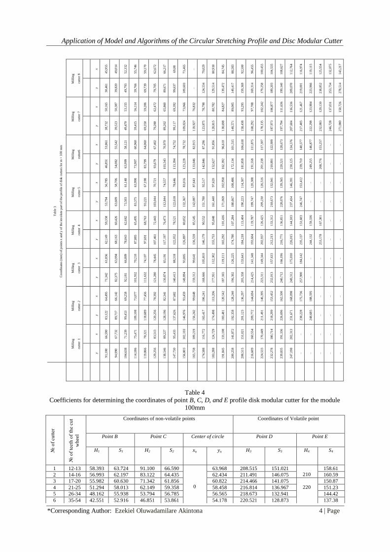
Disk cutters for cutting uncorrected gear wheels are made in the form of sets of 8, 15 or 26 cutters (Table 2). Each cutter in the set is used to cut wheels with a specific number of teeth. A set of 8 cutters is used for cutting
gears with a module of up to 8 mm. For a module over 8 mm, a set of 15 cutters should be used, and for more
precise work - a set of 26 cutters. The dimensions of the coordinates of the cutters' profiles are normalized and
are given in (table. 3) values of x and y coordinates for any point of the cutter profile, measured from the
bottom of the tooth cavity (Figure. 2).

Application of Model and Algorithms of the Circular Stretching Profile and Disc Modular Cutter
*Corresponding Author: Ezekiel Oluwadamilare Akintona 3 | Page
Type 1 Type II
A – Type I; B – Type II
Figure 2. Construction of the profile for the disk modular gear milling cutters:
Profile type IInstitute VNII proposed a special table of x(S) and y(H) coordinate values for any point of the cutter profile measured from the bottom of the tooth root, coordinates xz – centers of curvature in the tooth
root, values of radii r, and also points B, C, D, E profiles (Figure 2). The coordinates S3, H3 – set the position
of the involute point D, lying on the addendum circle; S4, H4 – set the position of the involute last point and
the transition to the dimensions of the cutter width B. The calculation of the coordinates for the cutter profile
points (Figure 2) is performed either in a tabular manner, or using the calculation form presented in
(Table 1.1). The capabilities of modern integrated CAD systems predetermine the expediency of
transferring information from a tabulated form into analytical. Expressions (calculation form), which
ensures higher accuracy of calculations with a significant reduction in the time required for this.
Table 2
Complete set of Disk Gear Cutter
№
cutters
Number of cutters in set №
cutters
Number of cutters in set
26 15 8 26 15 8
Cutting number of wheel teeth Cutting number of wheel teeth
1 12 12 12–13 5 26–27 26–29 26–34
1½ 13 13 – 5¼ 28–29 – –
2 14 14 14–16 5½ 30–31 30–34 –
2¼ 15 – – 5¾ 32–34 – –
2½ 16 15–16 – 6 35–37 35–41 35–54
3 17 17–18 17–20 6¼ 38–41 – –
3¼ 18 – – 6½ 42–46 42–54 –
3½ 19 19–20 – 6¾ 47–54 – –
3¾ 20 – – 7 55–65 55–79 55–134
4 21 21–22 21–25 7¼ 66–79 – –
4¼ 22 – – 7½ 80–102 80–134 –
4½ 23 23–25 – 7¾ 103–134 – –
4¾ 24–25 – – 8 135 135 135
Profile type II is designed for milling cutters No. 6-8 (z> 34; rb<rf) and consists of an involute BDE and a
straight line segment OA conjugated along a circular arc AB. Given in (table. 3 and 4) values are given for
module m = 100 mm. For other modulus values, the table values must be divided by 100 and multiplied by the
calculated modulus. The obtained values of the coordinates of the cutter profile are entered into the table and
used for graphical construction of the profile of the disk modular cutter performed on the drawing (Figure. 6).
2.1.2. Determination of the profile coordinates of the corrected (ξ ≠ 0) disc cutters with a high degree of
accuracy.
To cut corrected teeth of wheels, as well as uncorrected teeth of an increased degree of accuracy and wheels
with a modified tooth profile, disc cutters are used, the exact profile of which is determined by special
calculations. (Figure. 2)
Application of Model and Algorithms of the Circular Stretching Profile and Disc Modular Cutter
*Corresponding Author: Ezekiel Oluwadamilare Akintona 4 | Page
Table 4
Coefficients for determining the coordinates of point B, C, D, and E profile disk modular cutter for the module
100mm
Tab
le 3
Co
ord
inat
es (
mm
) o
f p
oin
ts x
an
d y
of
the
inv
olu
te p
art o
f th
e p
rofi
le o
f d
isk
cu
tter
s fo
r m
= 1
00
mm
Mil
lin
g
cutt
er 8
x
45
,955
49
,014
52
,332
55
,746
59
,170
62
,672
66
,217
69
,08
73
,465
–
79
,029
80
,918
84
,745
88
,583
92
,500
96
,455
100
,45
5
104
,53
5
108
,62
7
112
,76
4
116
,97
4
119
,11
5
125
,55
4
132
,07
5
143
,21
7
y
30
,461
39
,820
49
,793
59
,766
69
,739
79
,705
89
,671
99
,637
109
,60
3
–
124
,53
4
129
,51
4
139
,47
2
149
,41
7
159
,36
9
169
,31
4
179
,25
8
189
,20
3
199
,14
0
209
,07
0
219
,00
1
223
,96
6
238
,85
2
253
,73
4
278
,51
4
Mil
lin
g
cutt
er 7
x
50
,165
50
,387
53
,155
56
,114
59
,206
62
,472
65
,860
69
,392
73
,066
76
,832
78
,798
80
,782
84
,827
89
,005
93
,295
97
,708
102
,24
2
106
,87
7
111
,63
6
116
,53
6
121
,46
7
123
,98
4
129
,13
0
137
,03
1
150
,72
6
y
38
,732
39
,523
49
,470
59
,415
69
,350
79
,280
89
,202
99
,117
109
,02
4
118
,92
7
123
,87
5
128
,81
5
138
,69
8
148
,57
1
158
,43
8
168
,29
2
178
,13
5
187
,97
3
197
,79
4
207
,60
4
217
,40
5
222
,29
8
232
,08
3
246
,72
8
271
,08
0
Mil
lin
g
cutt
er6
x
53
,861
55
,542
58
,121
60
,960
64
,060
67
,402
70
,970
74
,752
78
,732
82
,915
87
,296
91
,856
96
,610
101
,51
5
106
,61
8
111
,87
5
117
,30
7
122
,90
9
128
,67
3
134
,57
6
140
,57
7
146
,87
7
153
,25
7
–
–
y
46
,851
54
,082
63
,999
73
,907
83
,799
93
,679
103
,54
3
113
,39
4
123
,22
8
133
,04
6
142
,84
6
152
,62
7
162
,39
2
172
,13
4
181
,85
8
191
,55
8
201
,23
8
210
,89
1
220
,52
1
230
,12
5
239
,71
0
249
,25
5
268
,77
6
–
–
Mil
lin
g
cutt
er 5
x
56
,785
58
,706
61
,148
63
,998
67
,198
70
,721
74
,557
78
,646
83
,016
87
,641
92
,517
97
,620
102
,95
8
108
,48
6
114
,30
7
120
,30
8
126
,51
6
132
,94
1
139
,56
5
146
,39
1
153
,41
2
–
–
–
–
y
53
,794
63
,609
73
,503
83
,375
93
,221
103
,04
4
112
,84
4
122
,61
8
132
,36
7
142
,08
7
151
,78
0
161
,44
0
171
,06
9
180
,66
7
190
,22
3
199
,74
7
209
,23
0
218
,67
3
228
,07
6
237
,43
4
246
,74
7
–
–
–
–
Mil
lin
g
cutt
er 4
x
59
,358
60
,426
62
,682
65
,495
68
,763
72
,443
76
,473
78
,521
80
,852
85
,545
90
,552
95
,848
101
,43
6
107
,28
4
113
,40
4
119
,78
7
126
,42
5
133
,31
2
136
,85
1
144
,10
3
151
,60
3
159
,33
6
167
,30
1
–
–
y
62
,149
68
,163
78
,043
87
,885
97
,691
107
,46
1
117
,19
7
122
,05
2
126
,89
7
136
,55
9
146
,17
9
155
,75
3
165
,29
2
174
,78
0
184
,21
8
193
,60
4
202
,93
7
212
,21
3
216
,77
1
226
,01
5
235
,13
7
244
,13
2
253
,17
8
–
–
Mil
lin
g
cutt
er 3
x
61
,856
63
,994
66
,809
70
,210
74
,107
78
,445
83
,191
88
,318
93
,805
99
,641
105
,81
0
112
,30
2
119
,11
1
126
,22
5
133
,64
3
141
,34
8
149
,34
4
157
,63
3
166
,19
6
175
,03
0
184
,14
2
–
–
–
–
y
71
,342
82
,375
92
,181
101
,93
2
111
,63
2
121
,28
0
130
,87
4
140
,41
3
149
,89
4
159
,31
2
168
,66
6
177
,95
1
187
,16
5
196
,30
2
205
,35
8
214
,42
5
223
,31
1
232
,01
3
240
,71
2
249
,31
2
257
,90
0
–
–
–
–
Mil
lin
g
cutt
er 2
x
64
,495
66
,142
69
,258
73
,077
77
,456
78
,392
82
,341
87
,682
93
,459
99
,648
106
,24
1
113
,20
6
120
,54
2
128
,24
0
136
,29
7
144
,69
4
146
,39
5
153
,43
2
162
,50
0
168
,09
8
175
,73
6
188
,59
5
–
–
–
y
83
,122
89
,717
99
,453
109
,10
8
118
,68
9
120
,25
6
128
,19
6
137
,62
6
146
,97
6
156
,24
2
165
,41
7
174
,49
8
183
,48
1
192
,35
8
201
,12
3
209
,77
2
211
,49
1
218
,29
9
226
,69
6
231
,67
1
238
,22
8
248
,68
5
–
–
–
Mil
lin
g
cutt
er 1
x
66
,590
67
,732
71
,239
75
,471
78
,321
83
,513
89
,227
95
,433
102
,10
3
109
,21
9
116
,77
2
124
,72
9
133
,10
8
141
,87
2
151
,02
1
160
,55
4
170
,44
9
180
,71
4
191
,33
6
202
,31
3
–
–
–
–
–
y
91
,100
94
,990
104
,63
8
114
,18
6
119
,86
6
129
,25
6
138
,54
6
147
,73
0
156
,80
3
165
,75
8
174
,58
8
183
,28
8
191
,84
5
200
,25
8
208
,51
5
216
,60
9
224
,53
3
232
,27
8
239
,83
5
247
,19
8
–
–
–
–
–
№ o
f cu
tter
№ o
f te
eth
of
the
cut
wh
eel
Coordinates of non-volatile points Coordinates of Volatile point
Point B Point C Center of circle Point D Point E
H1 S1 H2 S2 xц yц H3 S3 H4 S4
1 12-13 58.393 63.724 91.100 66.590
0
63.968 208.515 151.021
210
158.61
2 14-16 56.993 62.197 83.122 64.435 62.434 211.491 146.075 160.59
3 17-20 55.982 60.630 71.342 61.856 60.822 214.466 141.075
220
150.87
4 21-25 51.294 58.013 62.149 59.358 58.458 216.814 136.967 151.23
5 26-34 48.162 55.938 53.794 56.785 56.565 218.673 132.941 144.42
6 35-54 42.551 52.916 46.851 53.861 54.178 220.521 128.873 137.38

Application of Model and Algorithms of the Circular Stretching Profile and Disc Modular Cutter
*Corresponding Author: Ezekiel Oluwadamilare Akintona 5 | Page
Figure 3 Main parameters of disk modular milling cutter profile
Table 5
Dependencies for calculating the profile of a disk modular cutter № of dependencies Designation Dependencies
1 дδ
mz
S
z
tg
zд
*2
2
2 bδ
b дδ = δ -in vα
3 x
b
x
x
rc o sα =
ρ
4 x
xbxbx
inv
5 x xx
x sin
6 y xx
y cos
7 S xS 2
8 t ft= y -r
Designations: δd - half of the angular width of the depression along the pitch circle;δb - half of the angular width of the depression on
the base circle; θx - current polar angle at arbitrary points on the radius vector ρх; αх - current angle of pressure (engagement);δх -
half of the angular width on the circle of the radius vector ρх;x, y - coordinates of the profile point
When calculating, it is necessary to show a number of values of ρx - the radius vector of the points of the
involute profile of the gear wheel in the range from at z≤34 or ρx = rb at z> 34 and to ρx = ra. To do this, the
distance between adjacent points of the profile in height is set at the height of the tooth, taking into account that
the total number of points under consideration is usually taken within the limits depending on the required accuracy of the profile. Then the smallest radius vector will be equal to: ρx min = pf + Δp. Subsequent values of
ρx are calculated depending on the number of the point in question. Coordinate calculation data are summarized
in a table (Table 6) and are used to construct a profile of a disk modular cutter, a template and a counter-
template to check the manufacture of a cutter, as well as for profiling a relief cutter.
7 55-
134
38.290 50.015 38.732 50.165 51.850 222.298 123.984
230
130.40
8 135-
Infint
e
30.161 45.955 -- -- 4.007 44.114 223.966 119.115 123.33

Application of Model and Algorithms of the Circular Stretching Profile and Disc Modular Cutter
*Corresponding Author: Ezekiel Oluwadamilare Akintona 6 | Page
Table 6
Calculation of the coordinates of the profile of the disk modular cutter № of
Profile
point
,мм ,рад x, мм y, мм S0, мм t, мм
a1 94,22 0,991084 7 51'36'' 0,0008 0,0066 0,3814 0,627 94,233 1,254 0,043
a2 95,06 0,982326 10 4’48’’ 0,0022 0,0081 0,4653 0,772 95,066 1,544 0,087
a3 95,91 0,973621 13 29’33’’ 0,0041 0,0100 0,5734 0,959 95,908 1,918 0,130
a4 96.75 0,965167 15 31’40’’ 0,0063 0,0122 0,7004 1,182 96,749 2,364 0,174
a5 97,60 0,956762 16 17’32’’ 0,0088 0,0147 0,8436 1,437 97,590 2,874 0,218
a6 98,44 0,948598 18 51’43’’ 0,0116 0,0174 1,0010 1,719 98,429 3,438 0,261
a7 99,28 0,940572 19 17’58’’ 0,0145 0,0204 1,1710 2,029 99,267 4,058 0,305
a8 100,13 0,932587 21 37’15’’ 0,0177 0,0236 1,3524 2,363 100,104 4,726 0,349
a9 100,97 0,924829 23 50’53’’ 0,0211 0,0269 1,5444 2,721 100,939 5,442 0,392
Aa 101,81 0,917198 25 59’46’’ 0,0303 0,0362 2,0759 3,735 103,057 7,47 0,436
Ark 95,63 0,976471 12 46’08’ 0,0034 0,0093 0,5354 0,893 95,630 1,0708 0,479
The calculation of the values δд, δb, δх (in radians) is performed with accuracy of 0.000001, and in a
degree measure with an accuracy of up to. The accuracy of counting the coordinates of the profile points x, y,
S0, t is 0.001 mm. Conversion of angles from radian to degrees is carried out according to tables.[18] p. 596,
adj. X or by multiplying by 57.29578 and further converting fractions of a degree into minutes and seconds. The
coordinates of the points of non-involute profile elements are determined in accordance with GOST 10996-64
(Table 4) [19] Table. 121, p. 307. The values of the radius of curvature at the top of the cutter tooth (Figure. 3)
are recommended to be selected according to (table. 7).
Table 7
The value of the radii and abscissas of the profile of shaped gear cutting mills,mm z 12-13 14-16 17-20 21-25 26-34 35-54 55-134 Over 134
r 0.52 0.49 0.46 0.43 0.40 0.36 0.32 0.25
1x 0.2086 0.2150 0.2382 0.2640 0.2950 0,3200 0.3458 0.4000
Note: for a module other than m= 1 mm, the given data must be multiplied by the corresponding module
III. CALCULATION OF DESIGN PARAMETERS OF DISC MODULAR MILL 3.1.The main parameters - outer D and inner diameters, width B, the number of teeth z0 of uncorrected cutters
from the set (Figure. 4) are selected depending on the size of the module and the cutter number in accordance
with the data established by GOST 10996-64 (table.8 [17] p. 510, table. 13.11; [18] p. 391, table. 157).
Table 8 Basic dimensions of modular disk cutters, mm
m D d 0
z
Width B for number cutters
1 1½ 2 2½ 3 3½ 4 4½ 5 5½ 6 6½ 7 7½ 8
1,125 50 19 14 4,5 – 4,5 – 4 – 4 – 4 – 4 – 4 – 4
1,25 50 19 14 5 – 5 – 4,5 – 4,5 – 4,5 – 4,5 – 4 – 4
1,375 50 19 14 5,5 – 5,5 – 5 – 5 – 5 – 5 – 4,5 – 4,5
1,5 55 22 14 6 – 6 – 5,5 – 5,5 – 5 – 5 – 5 – 5
1,75 55 22 14 7 – 6,5 – 6,5 – 6,5 – 6 – 6 – 5,5 – 5,5
2 63 22 12 8 – 7,5 – 7,5 – 7 – 7 – 6,5 – 6,5 – 6
2,25 63 22 12 8,5 – 8,5 – 8 – 8 – 7,5 – 7,5 – 7 – 7
2,5 70 22 12 9,5 – 9,5 – 9 – 8,5 – 8,5 – 8 – 8 – 7,5
2,75 70 22 12 10,5 – 10 – 10 – 9,5 – 9 – 9 – 8,5 – 8
3 80 27 12 11,5 – 11 – 10,5 – 10,5 – 10 – 9,5 – 9,5 – 9
3,25 80 27 12 12 – 12 – 11,5 – 11 – 10,5 – 10,5 – 10 – 9,5
3,5 80 27 12 13 – 13 – 12,5 – 12 – 11,5 – 11 – 11 – 10,5
3,75 80 27 12 14 – 13,5 – 13 – 12,5 – 12 – 12 – 11,5 – 11
4 90 27 12 15 – 14,5 – 14 – 13,5 – 13 – 12,5 – 12 – 11,5
4,25 90 27 12 15,5 – 15 – 14,5 – 14 – 13,5 – 13 – 12,5 – 12
4,5 90 27 12 16,5 – 16 – 15,5 – 15 – 14,5 – 14 – 13,5 – 13
5 100 27 12 18 – 17,5 – 17 – 16,5 – 16 – 15,5 – 15 – 14,5
5,5 100 27 12 20 – 19 – 18,5 – 18 – 17,5 – 17 – 16 – 15,5
6 110 32 10 21,5 – 21 – 20 – 19,5 – 19 – 18 – 17,5 – 17

Application of Model and Algorithms of the Circular Stretching Profile and Disc Modular Cutter
*Corresponding Author: Ezekiel Oluwadamilare Akintona 7 | Page
6,5 110 32 10 23 – 22,5 – 21,5 – 21 – 20 – 19,5 – 19 – 18
7 110 32 10 24,5 – 24 – 23 – 22 – 21,5 – 21 – 20 – 19,5
8 125 32 10 28 – 27 – 26 – 25 – 24,5 – 24 – 23 – 22
9 125 32 10 31 31 30 30 29 29 28 28 27 27 27 26 26 25 24
10 140 40 10 34 34 33 33 32 32 31 31 30 30 29 29 28 28 27
11 140 40 10 37 37 36 36 35 34 34 33 33 32 32 31 31 30 29
12 160 40 10 41 40 39 39 38 37 37 36 36 35 35 34 34 33 32
14 160 40 10 47 46 46 45 44 43 43 42 41 41 40 39 39 38 37
16 180 50 10 53 52 52 51 50 49 48 48 47 46 45 45 44 43 42
3.2.When designing special gear cutters (corrected non-corrugated, increased accuracy and for modified
wheels), their outer diameter is determined (as for shaped relief cutters) depending on the diameter of the bore
and the height of the tooth H:
Figure.4. The main parameters of the disk modular cutter
The value (in mm) is taken from the normal range of sizes of the diameters of the holes of the plug-on
cutting tool, GOST 9472-83: 16, 19, 22, 27, 32, 40, 50 with the tolerance field H7 or H6, depending on the
height of the profile of the cutter tooth (table. 9).
Table 9
Values of the diameters of the bore of the profile cutters, mm Cutter tooth profile height h0 3 3-6 6-10 10-25 25-37 Over 37
Bore diameter d 16
19 22 27 32 40 50
The height of the cutter tooth H when determining the diameter D is roughly assumed:
Where;- ; -the maximum height of the tooth profile of the
cut wheel is selected from the calculated table of the values of the coordinates of the cutter profile (see Table 6). 3.3.The cutter width B is calculated to the nearest 0.1 mm using the formula:
.711,
Where - is the coefficient determined from the graph (Figure 5);- the maximum width of the profile of the root
of the tooth, selected from the calculated table of the values of the coordinates of the profile cutter width (in
mm) is recommended to be taken from the following row: 10;12;14;15;16;17;
18;22;24;25;26;28;30;32;34;35;36;38;40 and further every 5 mm
3.4.The number of teeth can be roughly calculated for cutters with mm (GOST 13838-68) with a straight flute
according to the formula:
=
=5.1

Application of Model and Algorithms of the Circular Stretching Profile and Disc Modular Cutter
*Corresponding Author: Ezekiel Oluwadamilare Akintona 8 | Page
And for cutters with mm (GOST 10996-64) with a reinforced hub and with a milled chip groove providing the
tooth with a stronger shape (Figure. 4):
Here it is recommended to take smaller coefficients for small diameters, and larger ones for large diameters of
cutters. The values of the quantities are specified during further calculations of the parameters,
graphical construction of the profile and design of the cutters, as well as in accordance with the data of the
given standards.
Figure.5. Graph for determining the cutter width ratio
B
0
π DК = tg α
z;
sin
б
B
tgtg ,
Where B
is the posterior angle at the apex of the tooth (i.e. on the outer diameter);- the Dб
posterior angle
on the lateral sides of the tooth, taken roughly; o o
бα =1 ,5 ...3 ; the angle of inclination of the tooth profile of
the outer diameter of the cutter, is selected according to table.10 depending on the number of the cutter. It is
allowed to use the calculated values, from (table.10). For precise finishing mills with a ground profile, the
amount of relief of the ground part K is determined by the above formula,
КК )4,1...2,1(1 =1.2 .
And the amount of relief of the unpolished part of the tooth is determined by the formula: К и К1values are
rounded to the nearest 0.5 mm.
3.6. Tooth height H for cutters with straight flute is calculated with an accuracy of 0.1mm using the formula;
, =10+4.5+1.36=15.86 Or with double profile relief:
.=10+
+1.36=16.36
For cutters with a milled chip groove (figure 4), the value of H is determined from the expression:
№ of
cutters 1 1½ 2 2½ 3 3½ 4 4½ 5 5½ 6 6½ 7 7½ 8
Profile
inclination
angles 5° 5°10 ́ 5°20 ́ 6°40 ́ 8°10 ́ 10° 9°40 ́ 10°30 ́ 11°30 ́ 11°50 ́ 14° 14°40 ́ 16°40 ́ 17° 18°
Angles
used for
the
calculation
б
B
5°
1°20 ́
15°
8°
1°40 ́
12°
14°
2°30 ́
10°

Application of Model and Algorithms of the Circular Stretching Profile and Disc Modular Cutter
*Corresponding Author: Ezekiel Oluwadamilare Akintona 9 | Page
=10+1.36=11.36,
Where H is the height of the working tooth profile approximately h=ra – rf, or more precisely from the
calculated table of profile coordinate values.
maxth ;
Kr - the radius of curvature for the flute, usually taken equal to 1…..5mm, depending on the
diameter of the cutters or calculated by the formula:
=
*sin
.
The value of angle depends on the amount of idle movement of the relief cam. With a cam idle stroke
of 60° (basic design case)
o
0
3 6 0ψ =
6 z =
=
=5
With 90°, cam idle, used for cutters with large chip flutes, the angle is defined as:
o
0
3 6 0ψ =
4 z=
=
=7.5
The largest chip groove (figure 4) is determined by the formula:
=10+4.5+1.36=15.86.
The angle of milling grooves 1
(figure 4) is usually chosen equal to the angle of inclination of the
tooth profile in this area or is taken constructively 1
3.7 The value of the angle of the profile of the chip grooves is roughly determined from equation
o o
0
3 6 0 °ν = + (1 6 ...2 2 )
(4 ...8 ) z =
= 29.5
And is equal to 18 °, 22 °, 25 °, and 30 °.
3.8. The width of the cutter tooth C at its base (Figure. 4) is determined from the expression: НС 75,0 If
this condition is not met, the outer diameter D is increased or the number of teeth is reduced. 0
z .
3.9 The length of the ground part of the back surface of the AB cutter tooth (Figure. 4) with double relief must
be at least 3
2 the length of the AC tooth and is determined by the formula:
3.10. The dimensions of the elements of the bore of the cutter are taken according to GOST 4020-82 or GOST
9472-84 [17] p. 170 table. 6.1,[18] p. 579 Appendix III.For the accepted diameter 70Hd or 6
0Hd of the hole
or (see paragraph 3.2) determine the dimensions of the longitudinal keyway - width 11bC and height 12Ht .
At the base of the groove perform rounding with a radius r, which can be replaced with a chamfer. 45min
r .
On both sides of the bore, bevels are made with a width of 0,2...5,1С mm at an angle of 45 °. For cutters
with a width of more than 15..20 mm, a recess with a diameter of 101 dd mm and a length
Bl )6,0...2,0( is made in the hole (Figure. 4) in order to reduce the contact surface of the mandrel with the
cutter hole. In this case, the length of precisely worked out grooves should be:
=2.4.
3.11. The thickness of the cutter body in the most dangerous section above the keyway must be at least.0.35d
3.12. The rake angle of disk modular cutters is adopted 0 1 0 B
. . . depending on the properties of the
material being processed and the type of cutter.Rough cutters (for preliminary cutting of a tooth) are designed

Application of Model and Algorithms of the Circular Stretching Profile and Disc Modular Cutter
*Corresponding Author: Ezekiel Oluwadamilare Akintona 10 | Page
with a rake angle 8 1 0 В
. . . in order to improve cutting conditions. The resulting inaccuracies in the
profile are compensated for by the finishing allowance.Finishing cutters (for finishing a tooth cavity) are made
with precise (usually ground) profiles and rake angles 0B
Otherwise, the profile of the cutter is subject to
correction.
3.13. Disk modular gear cutters (both solid and prefabricated) are made of high-speed steels of normal
performance P6M5, P12; Р9 in accordance with GOST 19265-73 with the hardness of the working part HRC 63
... 66.
IV. CONCLUSION During the work we faced the question of how to develop the optimal version of the cutting tool for a
given work piece. We adhered to the recommendations that during cutting, the specified accuracy of the part
should be ensured, the tool should be securely fastened to the machine and its geometry should provide cutting
conditions that best suit the given production conditions. The initial data for the design were working drawings of the part with the required dimension and deviations applied to them, the parameters of the machine on which
the work piece is fastened and processed.
Conflict of Interest
On behalf of all authors, the corresponding author states that there is no conflict of interest.
REFERENCES [1]. Linke, H.: Stirnradverzahnung: Berechnung, Werkstoffe, And Fertigung. München, Wien: Carl Hanser Verlag, 1996
[2]. Litvin, F. L., Fuentes, A.: Gear Geometry and Applied Theory. 2nd
Edition. Cambridge, New York, Port Melbourne Cape Town:
Cambridge University Press, 2004.
[3]. Roth, K.: Zahnradtechnik – Evolventen-Sonderverzahnungen zur Getriebeverbesserung: Evoloid-, Komplement-, Kei , Konische-,
Konus-, Kronenrad-, Torus-, Wälzkolbenverzahnungen, Zahnrad-Erzeugungsverfahren. Berlin, He NewYork: Springler Verlag,
1998.
[4]. Koganov I.A.Progressive machining of gear profiles and shaped surfaces. Tula: Priokskoe book, 1970.
[5]. Heisel, U.; Pasternak, S.; Storchak, M.; Stehle, T.: Jede Verzahnung mit einem Werkzeug herstellbar. In: – die Ma 2009. - 5, 44 –
45 pp.
[6]. Pasternak, S.: Investigation and optimization of the machining production of gears with profile-independent disc tools. Dissertation
University of Stuttgart, 2016.
[7]. The way to add toothed wheels. Blagut E. M., Danilchenko Yu. M.,Korotkiy. V., Krivosheya A. V., Meln Pasternak S. I.,
Rosenberg O. O. Patent UA15843, ICP В23F 5/00, Ukraine. Declared, 02.02.2006. Published on July 17, 2006.
[8]. A method of cutting bevel wheels on cnc machines. Nesterov, V. Ya .; Demichev, V.A .; Gurvich, E. L.: SU1720815, IPC B23F
9/00, CCCP. Declared: 01/02/1989. Published: 23.03.1992.
[9]. Wermeister, G .; Scherbarth, S .: New way to precise gears. WB workshop and operation. - 2011. 12. - 54-5
[10]. Zipse, H .; Siegler, R: With the courage to leave a gap. mav competence in machining. 2010. - 6, 26th p.
[11]. Pasternak S. I., Danilchenko Yu. M., Heisel U .: Machining strategies for gear cutting with disk-shaped milling Bulletin of the
National Technical University of Ukraine "KPI". Serial machine - 2015. - 74, No. 2. C
[12]. Danilchenko Yu.M. Krivosheya A.V., Pasternak S.I., Korotkiy Є. V. Kinematicsof shaping cylinders of gear wheels with a given
profile disc tool. Bulletin of NTUU “KPI”. Machine building series - 46. P. 104 - 108.
[13]. Danilchenko Yu. M., Krivosheya A. V., Pasternak S. І. Mathematical modeling of the laws of the disk instinct in the case of the
tooth parts of the appropriate profile. Bulletin of the National Technical University of Ukraine Series of machinery. - 2006. -- 49, p.
112 - 118.
[14]. Danilchenko Yu.M., Pasternak S. I., Krivosheya A. V. Productivity of the contour processing of toothed lance for tools. Bulletin of
NTUU “KPI”.Mechanical engineering series. 2008) 53, 215-225.
[15]. Heisel, U .; Danylchenko, Yu .; Pasternak, S .; Storchak, M., Schaal, M .: Serial machine on modeling of the gearing with disk
force ZWF - magazine for economical factory operation. 105 (2010) 7-8, 649-654.
[16]. Averyanov O.I. The modular principle of the construction of CNC machines. – M.: Mechanical Engineering, 1987. – 232 p.
[17]. Design and calculation of metal-cutting machines on a computer: textbook for universities/O.V. Taratynov, O.I. Averyanov, V.V.
Klepikov et al. – Moscow: MGIU, 2002. – 384 p.
[18]. Design of machine tools and machine tools. Handbook-textbook in 3 Vols. V.1. Designing machines/A.S. Pronikov et al. – M:
Publishing House of MGTU in. N.E. Bauman: Mechanical Engineering, 1994. – 444 p.
[19]. Bushuev V.V. Fundamentals of designing machine tools. – M.: Stankin, 1992. – 520 p.