application of hydrodynamic cavitation to wastewater …application of hydrodynamic cavitation to...
TRANSCRIPT

Application of Hydrodynamic Cavitationto Wastewater Treatment
Hydrodynamic cavitation is a promising application in wastewater treatment dueto its simple reactor design and capacity in large-scale operation. Theoretical stud-ies including the basic mechanism of pollutant degradation, modeling of pressuredistribution in the cavitation reactor, and bubble dynamics models coupled withchemical reactions are evaluated. Experimental setups with different cavitationreactors and operation parameters are compared for degrading specific kinds ofpollutants. The effort directions for both theoretical and experimental investiga-tions are suggested on the basis of the reviewed contents. Easy large-scale opera-tion, effective combination with intensified strategies, and capability to deal withbiorefractory or toxic compounds contribute to the great potential of hydrody-namic cavitation.
Keywords: Hydrodynamic cavitation, Pollutant degradation, Ultrasonic cavitation,Wastewater treatment
Received: August 13, 2015; revised: January 31, 2016; accepted: April 13, 2016
DOI: 10.1002/ceat.201500362
1 Introduction
Water pollution has become a serious problem due to largeamounts of domestic sewage and industrial effluent dischargedinto the water body. Wastewater coming from industries liketextile, pharmacy, pesticide, and petrochemical processing con-tains large amounts of organic compounds such as textile dyes,aromatic compounds, chlorinated hydrocarbons, and phenoliccompounds. These compounds are biorefractory or toxic to themicroorganisms and thus, conventional biochemical processesare not able to completely degrade them [1]. In the past decade,many researchers have tried different methods for the degrada-tion of organic pollutants [2–5], among which a new technolo-gy called hydrodynamic cavitation has drawn significant atten-tion. Compared with acoustic cavitation, it allows for easierrealization of scale-up applications [6–8].
Cavitation is a pressure-related process and occurs when thelocal pressure falls below the vapor pressure corresponding tothe liquid temperature. In case of acoustic cavitation, the localpressure fluctuation caused by acoustic waves is responsible forthe cavitation phenomenon [9], while the hydrodynamic cavi-tation occurs when liquid passes through a constriction-diverg-ing device, such as throttling valve, orifice plate, and venturi[10]. In the constriction region, the fluid velocity increases atthe expense of pressure drop and then cavitation bubbles form.
Subsequently, in the downstream region of constriction, thepressure is subjected to recovery because of the sectionalexpansion and cavitation bubbles collapse. Due to the collapse,an extreme environment with high temperatures of 1000–10 000 K, high pressures between 100 and 5000 bar, and high-speed microjet (102 m s–1 magnitude) can be formed [10]. As aconsequence, some highly reactive free radicals, such as HO.,H., HOO., HO2
., and H2O2 generate. All above-mentionedfactors favor the degradation reactions [11]. Therefore, hydro-dynamic cavitation has been considered as an effective meansto destruct contaminants in wastewater.
Recently, Gogate and Pandit [6–8, 11–16] published a seriesof excellent reviews on cavitation from reactor design to its ap-plication, while Adewuyi et al. [4, 17, 18] covered the subject ofwastewater treatment using acoustic cavitation. In this review,more attention is paid to the application of hydrodynamic cavi-tation to wastewater treatment. Different aspects of hydro-dynamic cavitation used for wastewater treatment areaddressed. The emphasis is focused on both the related theoret-ical development and the experimental setups applied in theexperiments. Some important contributions are incorporated,and their advantages and disadvantages are also compared.Energy efficiency and economy are assessed and finally, someuseful recommendations and effort directions are provided toenable efficient large-scale operations for hydrodynamic cavita-tion technology.
2 Theoretical Development
2.1 Degradation Mechanism
The degradation of contaminants is usually interpreted as thephysical and chemical effects induced by the bubble collapse.
Chem. Eng. Technol. 2016, 39, No. 8, 1363–1376 ª 2016 WILEY-VCH Verlag GmbH & Co. KGaA, Weinheim www.cet-journal.com
Yuequn Tao1,2
Jun Cai1
Xiulan Huai1
Bin Liu1,2
Zhixiong Guo3
1Institute of EngineeringThermophysics, ChineseAcademy of Sciences, Beijing,China.
2University of Chinese Academyof Sciences, Beijing, China.
3Department of Mechanicaland Aerospace Engineering,Rutgers, The State Universityof New Jersey, Piscataway, NJ,USA.
–Correspondence: Dr. Jun Cai ([email protected]), Institute ofEngineering Thermophysics, Chinese Academy of Sciences, No. 11,North 4th Ring West Road, Haidian District, Beijing 100190, China;Prof. Zhixiong Guo ([email protected]), Department of Mechanicaland Aerospace Engineering, Rutgers, The State University of NewJersey, 98 Brett Road, Piscataway, NJ 08854, USA.
Review 1363

There are a number of illustrations in the literature dealingwith the mechanism of cavitation-induced chemical transfor-mations. These studies have shown that wastewater treatmentdue to cavitation should be attributed to the mechanical (e.g.,shear stress), chemical (e.g., free radicals), and thermal effects(e.g., hot spots) induced by bubble collapse. The strong shearstress, generated during bubble collapse [19], can break downthe carbon-carbon bond and thus enable the direct decomposi-tion of organic macromolecules into low-molecular organiccompounds. Besides, local hot spots are generated as the bub-ble radius contracts violently. Under high-temperature condi-tions of the gas inside the bubble or at the gas-liquid interface,the organic molecules can be directly decomposed into inor-ganic or low-molecular organic compounds during bubble col-lapse. This process, which takes place in the solution, is similarto a combustion reaction process and is called liquid-phasecombustion. Moreover, water molecules trapped inside thebubble will be decomposed into free radicals [20]. These freeradicals will participate in oxidation reactions taking place atthe gas-liquid interface or in the bulk liquid.
The specific degradation process is determined by the prop-erties of pollutants. For example, rhodamine B is destructed byhydroxyl radicals at the bubble interface or within the bulksolution because of the low vapor pressure [21]. With the effectof hydroxyl radicals, polyaromatic rings are first separatedfrom the chromophore at the initial stage and then degraded[5, 22]. The degradation of Red K-2B is mainly due to thecleavage of the conjugate structures in the molecule, and thearomatic groups are just destroyed partly [23]. For the degrada-tion of chitosan solution, there is no obvious modification ofthe chemical structure of degraded chitosan, and the reactiononly causes the cleavage of b-(1,4)-glycosidic linkages [24].
It should be noted that the total amount of degradationdepends on the cavitation intensity and the number of cavita-tion events. Two important parameters known as cavitationnumber Cv
1) [25] and cavitation event rate J [26] have beenintroduced to characterize these two aspects:
Cv ¼P2 � Pv
1
2rv2
0
(1)
and
J ¼ J0exp �Gð Þ (2)
where P2 is the fully recovered pressure downstream, Pv is thesaturated vapor pressure of the liquid, v0 is the velocity of theliquid at the constriction position, J0 is the normalized pre-exponential factor, and G denotes the normalized Gibbs activa-tion energy.
2.2 Pressure Driving the Motion of Bubbles
Adequate quantification of both the pressure and velocity dis-tribution in a cavitation reactor is critical to quantitatively ana-lyze the bubble dynamics and the related chemistry. Among all
the reported approaches, the liner pressure recovery approachis the simplest, but is especially adequate to a geometry gener-ating relatively low turbulence intensity, e.g., a venturi tube.Yan et al. [27] used this kind of method to consider the behav-ior of a single bubble in the orifice-plate reactor (Fig. 1).
Through time and space conversion [28], the local pressureat any position downstream is expressed as:
P ¼ Pv þP2 � Pv
tt (3)
where P is the axial pressure, t is the specific moment corre-sponding to the geometrical position, and t is the total time forthe pressure recovery. By means of this method, the bubble willexperience a stable oscillation and produce pressure pulses withextremely low amplitude. Such nonviolent oscillation is notable to bring about the observed chemical effects. Thus, thisapproach certainly loses its validity in modeling the cavitationflow with chemical reactions.
Moholkar and Pandit [29] proposed a more realistic ap-proach by incorporating the turbulent fluctuation effect. Thebubbles oscillate in the form of transient state instead of stablestate in a nonturbulent model. In comparison with the nontur-bulent condition, the bubble has larger growth rates as well ashigher amplitude of pressure pulse. Cai et al. [30, 31] used theturbulence model to investigate the bubble behavior and theresultant temperature evolution inside the bubble. They foundthat both collapse pressure and temperature increased afterconsidering the effect of turbulence. Gogate and Pandit [13]applied the turbulence model to determine the magnitude ofpressure pulse during the bubble collapse in an orifice flow,and also found a significant increase in the magnitude of pres-sure pulse. All these are attributed to the violent collapses ofcavities caused by the turbulence action. It should be noted thatthe pressure profile consists of two parts in Moholkar andPandit’s model, i.e., linear recovery pressure and turbulent fluc-tuating pressure. Nevertheless, it can still not reflect the real
www.cet-journal.com ª 2016 WILEY-VCH Verlag GmbH & Co. KGaA, Weinheim Chem. Eng. Technol. 2016, 39, No. 8, 1363–1376
Figure 1. Schematic of the flow and pressure distribution down-stream of the orifice plate.
–1) List of symbols at the end of the paper.
1364 Review

pressure distribution in a cavitation reactor. With the develop-ment of computational fluid dynamics (CFD) technology, it ispossible to obtain more realistic pressure distributions in thereactor. The key is to legitimately substitute the discrete CFDsimulation results into the bubble dynamics calculation.
2.3 Bubble Dynamics Models Coupledwith Chemical Reactions
Various models have been proposed to study the link betweenbubble dynamics and formation of free radicals. Among these,the investigations conducted by Storey and Szeri [20, 32], Yasuiet al. [33, 34], and Toegel et al. [35] are regarded to be a land-mark paving the way for the related studies.
Yasui [33] developed a model of single-bubble sonochemis-try. By considering the compressibility of liquid and the effectof evaporation and condensation of water vapor, a new formu-lation of bubble dynamic equation is included. The conserva-tions of mass, momentum, and energy are analytically calcu-lated and the effects of the thermal conduction both inside andoutside the bubble, the kinetic energy of gas, and the chemicalreactions under high-temperature conditions during bubblecollapse are all analyzed. The number of HO. radicals dissolv-ing into the surrounding liquid from the interior of the bubbleis further calculated [34].
By considering mass transfer, nonequilibrium vapor conden-sation and evaporation, and chemical reactions, Storey andSzeri [20] firstly presented a general method solving the partialdifferential equations for bubble dynamics. Undoubtedly, themost precise treatment method is the full-depth numerical sim-ulation, but the calculation process is very complicated to solvethese mutual coupling equations. Later, they developed areduced model consisting of only ordinary differential equa-tions [32]. Toegel et al. [35] proposed a relatively simple diffu-
sion-limited model based on boundary layer approximation.According to this boundary layer approximation, the regionsinside the bubble are divided into two sections, i.e., core andboundary layer. The spatial distribution of species concentra-tion is uniform in the core region, but changes sharply insidethe boundary layer. The boundary layer thickness is calculatedthroughout the lifetime of cavity, and two regions are treatedseparately. This kind of approach reduces the solving difficulty,but still preserves the accuracy. Most of the later theoreticalstudies were based on these models. A brief overview aboutthese studies is given in Tab. 1.
It should be noted that the acceptability of a model and itssolution schemes strongly depend on the assumptions em-ployed in its derivation. Most of the previous investigationswere based on the uniform cavity interior model, while Mishraet al. [36] introduced a model based on the multiphase latticeBoltzmann method that allowed for the couple of reactionkinetics and hydrodynamics in a collapsing cavity. This kind ofcouple can lead to highly inhomogeneous concentration of sol-utes, and thus bring about the enhancement of concentration-dependent reaction rates.
2.4 Deficiency of the Theoretical Investigation
There are three regions where chemical reactions occur in acavitation bubble: the interior of the bubble, the interfacebetween bubble and liquid, and the bulk liquid field. Althoughthere already exist some numerical calculations of the chemicalreaction rate inside a collapsing bubble, the lifetime of differentradicals and the main reaction region are not yet understoodclearly, and there is a lack of quantitative description of thereactions between free radicals and contaminants from the per-spective of chemical reaction kinetics. Since the previous inves-tigations are based on the single spherical bubble assumption
Chem. Eng. Technol. 2016, 39, No. 8, 1363–1376 ª 2016 WILEY-VCH Verlag GmbH & Co. KGaA, Weinheim www.cet-journal.com
Table 1. Bubble dynamics models considering chemical reactions.
Researchers Important features of the models
Yasui et al. [34] Nonequilibrium evaporation and condensation of water vapor at the bubble wall, chemical reactions and the dissolutionof chemical products into the surrounding liquid, thermal conduction and diffusion of gases and vapor are taken intoaccount.
Capocelli et al. [81] Simulations of single-bubble dynamics with chemical reactions were conducted. The radical production rate that varieswith initial bubble size was obtained.
Kumar et al. [82] In addition to incorporation of heat transfer and solvent vapor transport across a bubble during radial motion, thiscavitation model also considered the bubble-flow and bubble-bubble interactions. Flow regime maps were presentedaccording to the combinations of design and process parameters.
Kumar and Moholkar [83] The diffusion-limited model of cavitation bubble dynamics was coupled to hydrodynamic characteristics of the flowthrough an orifice.
Mishra et al. [36] A model based on the multiphase lattice Boltzmann method (LBM) considering inhomogeneous concentrations of thesolute was presented.
Sharma et al. [65] An empirical correlation for predicting the pressure was established as a function of operating parameters. The Webernumber criterion for the stability of the growing bubble was used.
Krishnan et al. [84] Both the bubble dynamics model and the associated heat and mass transfer model for the orifice flow were establishedbased on the following approximations: (i) only turbulent velocity fluctuation along the flow direction was concerned;(ii) thermodynamic equilibrium was constituted during the bubble collapse.
Review 1365

when studying the degradation effect of hydrodynamic cavi-tation, it is difficult to quantitatively compare the calculationresults with the experimental data. A key step to solve thisproblem is to develop reasonable theoretical correlations toquantify the cavitation event number in different cavitation re-actors under various operating conditions. Hence, more refinedmodels which relax previous assumptions need to be developedfurther. Furthermore, the pressure profiles used in previousstudies are still not the real pressure distribution of liquids in acavitation reactor. More accurate pressure achieved by CFDmethod should be introduced into refined cavitation models.
3 Experimental Studies
3.1 Typical Scheme of the Experimental System
Among available experimental studies [8, 14, 37–39], the mostcommon system is illustrated in Fig. 2. It consists of a closedcirculation loop comprising a reservoir, a pump, control valves,a cavitation reactor, and measurement gauges. Water ispumped from the reservoir branches into two lines, i.e., a mainline where hydrodynamic cavitation takes place and a by-passline that is used to control the pressure and flow rate. As tem-perature has a significant effect on cavitation, a cooling systemis provided to control the liquid temperature.
3.2 Hydrodynamic Cavitation Reactors
3.2.1 Rotating Device
When liquid swirls rapidly around the axis of a rotating devicein a chamber, the local pressure near the central region will de-crease. If it falls below the vapor pressure of the liquid, vortexcavitation occurs. Subsequently, as water moves towards thebottom surface of the chamber where the pressure rises rapidly,cavitation bubbles collapse. Wang et al. [21, 40] carried outdegradation experiments of rhodamine B and alachlor by usingthe reactor shown in Fig. 3. A pseudo-first-order degradationreaction was detected in all experimentalcases. The operating conditions, such aspressure, temperature, initial concentrationof pollutant, pH, and H2O2 concentration,were found to have significant effects onthe degradation rate.
Considering that the opposite move-ments of two shear layers can generateshear cavitation, Petkovsek et al. [41, 42]used a novel rotation cavitation generatorto remove pharmaceuticals in water. Thegenerator is based on two facing rotorswith special radial grooves spinning in theopposite direction, as indicated in Fig. 4.This kind of cavitation generator hasadvantages such as large cavitation volume,rapid pressure recovery, low pressure loss,and easy installation.
Recently, another device which can generate shear cavitationwas proposed by Petkovsek et al. [43], as displayed in Fig. 5. Anoutstanding feature of this device is that it works not only ascavitation generator, but also as driving pump. Such structureavoids additional pressure drop. The results indicate that thiskind of device can bring about better disintegration of thesludge and higher biogas production for the pretreatment ofthe waste-activated sludge.
Based on a rotor and a stator, Badve et al. [44, 45] proposedanother kind of cavitation reactor, as demonstrated in Fig. 6.The rotor is presented in the form of a solid cylinder withindentations on its surface, and the cavitation is formed on thesurface of the rotor as well as within the indentations due tohigh-speed rotation. Testing the wastewater in the papermak-ing industry, almost 90 % chemical oxygen demand (COD)reduction was achieved.
www.cet-journal.com ª 2016 WILEY-VCH Verlag GmbH & Co. KGaA, Weinheim Chem. Eng. Technol. 2016, 39, No. 8, 1363–1376
Figure 2. Typical experimental system.
Figure 3. Rotating cavitation reactor.
1366 Review

3.2.2 Liquid Whistle Reactor
A typical liquid whistle reactor consists of an orifice tube and ablade, as presented in Fig. 7. With real industrial wastewater,Chakinala et al. [46] conducted an experimental study usingthis kind of reactor. Wastewater flows through the orifice tubeand generates hydrodynamic cavitation in a high-speed liquidjet. Then, the jet is projected over the edge of the adjacentblade, creating pressure fluctuation and bubble collapse. Themain advantage of this reactor lies in the highly efficient mix-ing. When combined with the Fenton process, such cavitationstructure can achieve 60–80 % removal of total organic carbon(TOC).
3.2.3 Orifice Plate Reactor
Compared with other cavitation generators, a multiple-holeorifice plate offers maximum flexibility over the design param-
eters, making it extensively applied [24, 47–49]. This kind ofreactor may have different arrangement of holes to achieve thedesired cavitation intensity and cavitation event number. Sometypical arrangements of holes are illustrated in Fig. 8.
Two parameters are used to characterize the orifice plate, i.e.,a and b, which are defined as:
a ¼ npdh
np dh
2
� �2 (4)
b ¼ ndh
dp
!2
(5)
where n is the total number of holes, dh isthe hole diameter, and dp is the pipe diame-ter. It has been qualitatively demonstratedthat the degradation rate of pollutants in-creases with higher a and lower b for a cer-tain flow area. Differences just exist inquantitative aspect [50], which is due tovarying cavitation intensities required forthe desired chemical transformations. Forexample, the cavitation intensity necessaryfor the decomposition of rhodamine B ismuch higher than that for KI decomposi-tion [5]. Therefore, varying a and b willlead to a more obvious change for KI de-composition.
Chem. Eng. Technol. 2016, 39, No. 8, 1363–1376 ª 2016 WILEY-VCH Verlag GmbH & Co. KGaA, Weinheim www.cet-journal.com
Figure 4. Cavitation reactor based on two rotors.
Figure 5. Shear cavitation generator and pump.
Figure 6. Cavitation reactor based on a rotor and a stator.
Figure 7. Liquid whistle reactor.
Figure 8. Typical arrangements of orifice plates.
Review 1367
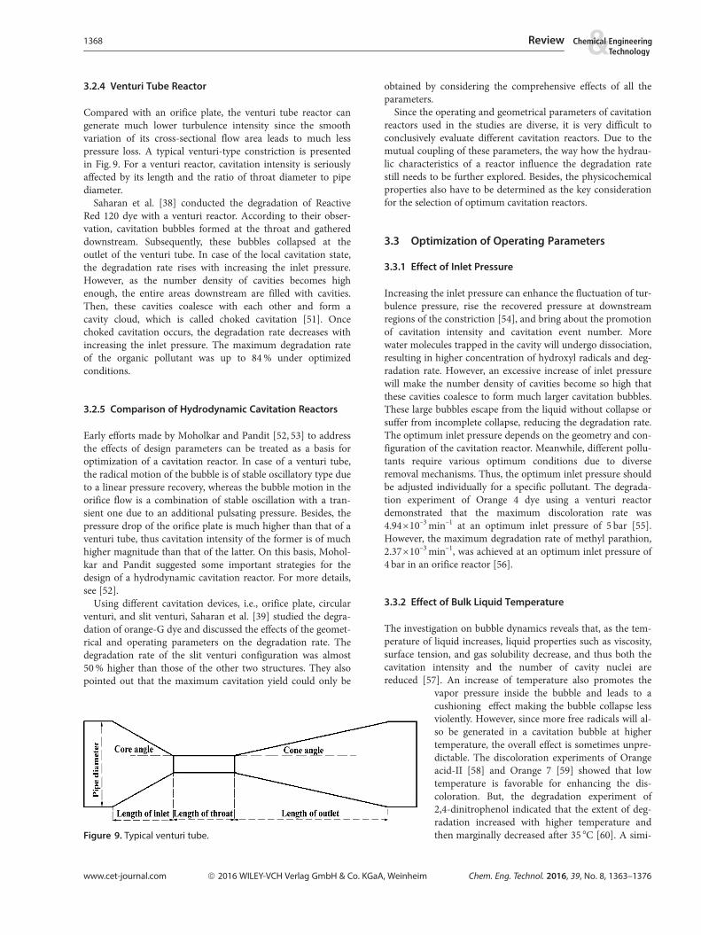
3.2.4 Venturi Tube Reactor
Compared with an orifice plate, the venturi tube reactor cangenerate much lower turbulence intensity since the smoothvariation of its cross-sectional flow area leads to much lesspressure loss. A typical venturi-type constriction is presentedin Fig. 9. For a venturi reactor, cavitation intensity is seriouslyaffected by its length and the ratio of throat diameter to pipediameter.
Saharan et al. [38] conducted the degradation of ReactiveRed 120 dye with a venturi reactor. According to their obser-vation, cavitation bubbles formed at the throat and gathereddownstream. Subsequently, these bubbles collapsed at theoutlet of the venturi tube. In case of the local cavitation state,the degradation rate rises with increasing the inlet pressure.However, as the number density of cavities becomes highenough, the entire areas downstream are filled with cavities.Then, these cavities coalesce with each other and form acavity cloud, which is called choked cavitation [51]. Oncechoked cavitation occurs, the degradation rate decreases withincreasing the inlet pressure. The maximum degradation rateof the organic pollutant was up to 84 % under optimizedconditions.
3.2.5 Comparison of Hydrodynamic Cavitation Reactors
Early efforts made by Moholkar and Pandit [52, 53] to addressthe effects of design parameters can be treated as a basis foroptimization of a cavitation reactor. In case of a venturi tube,the radical motion of the bubble is of stable oscillatory type dueto a linear pressure recovery, whereas the bubble motion in theorifice flow is a combination of stable oscillation with a tran-sient one due to an additional pulsating pressure. Besides, thepressure drop of the orifice plate is much higher than that of aventuri tube, thus cavitation intensity of the former is of muchhigher magnitude than that of the latter. On this basis, Mohol-kar and Pandit suggested some important strategies for thedesign of a hydrodynamic cavitation reactor. For more details,see [52].
Using different cavitation devices, i.e., orifice plate, circularventuri, and slit venturi, Saharan et al. [39] studied the degra-dation of orange-G dye and discussed the effects of the geomet-rical and operating parameters on the degradation rate. Thedegradation rate of the slit venturi configuration was almost50 % higher than those of the other two structures. They alsopointed out that the maximum cavitation yield could only be
obtained by considering the comprehensive effects of all theparameters.
Since the operating and geometrical parameters of cavitationreactors used in the studies are diverse, it is very difficult toconclusively evaluate different cavitation reactors. Due to themutual coupling of these parameters, the way how the hydrau-lic characteristics of a reactor influence the degradation ratestill needs to be further explored. Besides, the physicochemicalproperties also have to be determined as the key considerationfor the selection of optimum cavitation reactors.
3.3 Optimization of Operating Parameters
3.3.1 Effect of Inlet Pressure
Increasing the inlet pressure can enhance the fluctuation of tur-bulence pressure, rise the recovered pressure at downstreamregions of the constriction [54], and bring about the promotionof cavitation intensity and cavitation event number. Morewater molecules trapped in the cavity will undergo dissociation,resulting in higher concentration of hydroxyl radicals and deg-radation rate. However, an excessive increase of inlet pressurewill make the number density of cavities become so high thatthese cavities coalesce to form much larger cavitation bubbles.These large bubbles escape from the liquid without collapse orsuffer from incomplete collapse, reducing the degradation rate.The optimum inlet pressure depends on the geometry and con-figuration of the cavitation reactor. Meanwhile, different pollu-tants require various optimum conditions due to diverseremoval mechanisms. Thus, the optimum inlet pressure shouldbe adjusted individually for a specific pollutant. The degrada-tion experiment of Orange 4 dye using a venturi reactordemonstrated that the maximum discoloration rate was4.94 ·10–3 min–1 at an optimum inlet pressure of 5 bar [55].However, the maximum degradation rate of methyl parathion,2.37 ·10–3 min–1, was achieved at an optimum inlet pressure of4 bar in an orifice reactor [56].
3.3.2 Effect of Bulk Liquid Temperature
The investigation on bubble dynamics reveals that, as the tem-perature of liquid increases, liquid properties such as viscosity,surface tension, and gas solubility decrease, and thus both thecavitation intensity and the number of cavity nuclei arereduced [57]. An increase of temperature also promotes the
vapor pressure inside the bubble and leads to acushioning effect making the bubble collapse lessviolently. However, since more free radicals will al-so be generated in a cavitation bubble at highertemperature, the overall effect is sometimes unpre-dictable. The discoloration experiments of Orangeacid-II [58] and Orange 7 [59] showed that lowtemperature is favorable for enhancing the dis-coloration. But, the degradation experiment of2,4-dinitrophenol indicated that the extent of deg-radation increased with higher temperature andthen marginally decreased after 35 �C [60]. A simi-
www.cet-journal.com ª 2016 WILEY-VCH Verlag GmbH & Co. KGaA, Weinheim Chem. Eng. Technol. 2016, 39, No. 8, 1363–1376
Figure 9. Typical venturi tube.
1368 Review

lar trend was also observed in the degradation of alachlor[40]. The degradation rate increased with rising the tempera-ture in the range of 30–40 �C and decreased when the temper-ature exceeded 40 �C.
3.3.3 Effect of pH
Usually, an acid condition is recommended for pollutant degra-dation by hydrodynamic cavitation [22, 54, 55, 61–63]. Suchcondition favors the generation of hydroxyl radicals due to thedecomposition of hydrogen peroxide and impedes the recom-bination reaction among free radicals. The effect of solutionpH on the extent of degradation of diclofenac sodium wasinvestigated by varying the initial pH in the range of 4–7.5[61]. The degradation rate was raised from 14.7 to 26.8 % whenchanging the pH from 7.5 to 4. Similarly, the degradationexperiment of imidacloprid demonstrated that the maximumrate of degradation was obtained at an optimum pH of 3.Under alkaline conditions, the extent of degradation was muchlower than that under acidic conditions [62].
3.3.4 Effect of Initial Pollutant Concentration
For the pseudo-first-order degradation reaction induced bycavitation, the reaction process can be described as [40]:
C ¼ C0e�kt (6)
or
k ¼ � ln C=C0ð Þ=t (7)
where C is the pollutant concentration at time t, C0 is the initialconcentration, and k is the degradation rate constant.
It can be seen from Eq. (7) that increasing the initial pollu-tant concentration will decrease the degradation rate [40]. Ifcavitation conditions keep unchanged, the amount of HO. rad-icals in the system would be constant. But, the total pollutantamount in the solution increases with higher initial pollutantconcentration. Therefore, the degradation rate is reduced.Nevertheless, the increase of the initial pollutant concentrationwill also make more pollutants captured by HO., thereby thetotal decomposition amount becomes higher [64]. The degra-dation experiment of imidacloprid using the slit venturi provedthat the pseudo-first-order rate constant increased from0.79 ·10–3 to 1.27 ·10–3 min–1 with decreasing the initial con-centration from 60 to 20 ppm [62].
3.3.5 Effect of Initial Radius of the Nuclei
Cavities with lower initial size will grow to a larger extent andgive rise to more violent collapse [65]. Hence, decreasing theinitial radius will promote the pressure pulse caused by thebubble collapse and enhance the overall effect of hydrodynamiccavitation [13, 66].
3.3.6 Effect of Physicochemical Properties of the Liquid
According to [28, 51, 57, 67], the favorable conditions forenhancing cavitation effects are low liquid vapor pressure, lowviscosity, and high surface tension. An increase of the vaporpressure will enhance the vapor content inside the cavity. Asa consequence, the intensity of bubble collapse decreases dueto the cushioning effect caused by the continuous condensa-tion of vapor. Therefore, liquids with lower vapor pressurewill generate higher cavitation intensity. Increasing the vis-cosity will raise the threshold pressure of the cavitation eventsince it has to overcome a stronger natural cohesive force.Hence, there is a better cavitation effect in those fluids withlower viscosity. The pressure caused by surface tension canbe expressed as [68]:
Ps ¼2sR
(8)
where s is the surface tension coefficient. The pressure causedby surface tension will accelerate the bubble contraction pro-cess. Hence, the bubbles collapse more violently as the surfacetension increases and the resultant final collapse temperatureand pressure are marginally higher as well.
3.4 Deficiency of the Experimental Investigations
Experiments have proved that hydrodynamic cavitation candegrade many organic pollutants. Nevertheless, most of themare conducted in laboratory scale with single-component solu-tion and very few studies deal with multicomponent solutionand actual industrial wastewater [42, 44, 49, 69]. Overall, basedon these experiments, some coherent rules of chemical reactiondynamics and influencing factors have been obtained from thequalitative perspective, but some problems still exist in view ofquantitative analysis.
Considering the cavitation reactor, there is a lack of compari-son and validation of the results since various self-made deviceswere used in different research groups. To solve this problem,standardized devices which only consist of commercially avail-able parts would be helpful. These standardized cavitation devi-ces with different flow fields, turbulence characteristics, andgeometrical parameters are demanded to investigate the effectsof such factors on degradation characteristics. Besides, experi-ments with different scales should be carried out to addressscale-up issues, such as the alteration of flow field and turbu-lence characteristics in large scale.
In terms of properties of pollutant substrates, there are stillno clear correlations between physicochemical parametersand degradation conversion. On the one hand, the numberof substrates in some experiments is probably too small todraw the generalized statements. On the other hand, it is ofgreat difficulty to compare these data from different experi-ments due to the discrepancy of cavitation devices and oper-ating conditions. Moreover, some recent studies have usedsynthetically made effluents. As the actual industrial waste-water contains variable amounts of other compounds, theresults achieved under these conditions may not be repro-duced with actual wastewater.
Chem. Eng. Technol. 2016, 39, No. 8, 1363–1376 ª 2016 WILEY-VCH Verlag GmbH & Co. KGaA, Weinheim www.cet-journal.com
Review 1369

4 Hydrodynamic Cavitationwith Intensified Strategies
Hydrodynamic cavitation has application potential in waste-water treatment, but sometimes it is also difficult to obtainsatisfactory treatment efficiency by using hydrodynamic cavita-tion alone. In these situations, the process could be supple-mented by other advanced oxidation processes (AOPs) to gen-erate more oxidizing agents.
4.1 Effect of H2O2 Addition
Hydrogen peroxide and water molecules can be dissociatedforming radicals:
H2O fi HO�þH� (9)
H2O2 fi HO�þHO� (10)
H2O2þHO�fi H2OþHO2� (11)
In the presence of cavitation, hydrogen peroxide will show asynergetic effect due to the supply of additional hydroxyl radi-cals, but in case of excessive addition, it can also scavenge thegenerated hydroxyl radicals. Thus, the use of hydrogen perox-ide is favored only in optimum concentrations. The synergeticeffect of hydrogen peroxide on hydrodynamic cavitation wasinvestigated for the degradation of Reactive Red 120 dye andRed 88 Dye [38, 63]. Compared with only 60 % reduction ofcolor and 28 % reduction of TOC in case of only hydrodynamiccavitation, almost 100 % decolonization and 60 % reduction ofTOC were obtained when the molar ratio of added H2O2 todye concentrations was 1:60. There was only 13.15 % reductionof color using the same amount of H2O2 addition withouthydrodynamic cavitation.
On the one hand, the addition of H2O2 provides supplemen-tary oxidizing agents. On the other hand, hydrodynamic cavi-tation enhances the decomposing of H2O2 and also the micro-mixing of reactants. Thus, the combination of hydrodynamiccavitation and H2O2 could have a better effect as compared tothe single application of these processes. However, there wasno further increase in color and TOC reduction when exceed-ing this addition concentration.
4.2 Combination with Advanced Fenton Process(AFP)
AFP is one of the AOPs, in which highly reactive hydroxyls areproduced by decomposition of hydrogen peroxide with ferrousion (Fe2+) as catalyst in an acidic milieu. The exact reactionmechanism leading to enhanced HO� generation is given as fol-lows [70, 71]:
Fe2þþH2O2 fi Fe3þþHO�þOH� (12)
Fe2þþHO�fi Fe3þþOH� (13)
Fe3þþH2O2 fi FeOOH½ �2þþHþ (14)
FeOOH½ �2þfi Fe2þþHOO� (15)
Fe3þþHOO�fi Fe2þþO2þHþ (16)
To maximize the effectiveness of AFP, such factors as solu-tion pH, ferrous ion concentration, hydrogen peroxide loading,and operating temperature should be optimized. By using dif-ferent additives like hydrogen peroxide, carbon tetrachloride,and Fenton’s reagent, Joshi and Gogate [72] conducted a studyon dichlorvos degradation. Effects of different ratios of FeSO4/H2O2 were investigated. The results indicate that at a fixed con-centration of H2O2 both the degradation rate constant and theextent of removal rise significantly with increasing the FeSO4
loading. Similar results were reported by Patil and Gogate [56]for degradation of methyl parathion using the same device.
The initial concentration and pH of the solution play an im-portant role in the Fenton process. Pradhan and Gogate [54]investigated the removal of p-nitrophenol with 5 and 10 g L–1
initial concentrations. In case of using hydrodynamic cavita-tion alone, the removal for 5 g L–1 initial concentration ofp-nitrophenol was 53.4 % whereas it was 44.8 % for 10 g L–1 ini-tial concentration under the same conditions. After combina-tion with AFP, the maximum extent of degradation increased.For 5 g L–1 initial concentration, a maximum removal of 63.2 %was obtained at 1 g L–1 FeSO4 and 5 g L–1 H2O2 loadings. For10 g L–1 initial concentration, the maximum removal of 56.2 %was observed at 1 g L–1 FeSO4 and 7.5 g L–1 H2O2 loadings. Forthe higher pollutant concentration, higher loading of hydrogenperoxide is required to yield more oxidizing agents. The maxi-mum removal was obtained at pH 3.75 because the generationof hydroxyl radicals and their oxidation capacity were favoredunder acidic condition. When the solution was in alkaline con-dition (pH 8.0), the extent of removal decreased considerablysince both the formation of iron species and their catalyticactivities were suppressed by the pH of the solution.
4.3 Combination with Acoustic Cavitation
Compared with acoustic cavitation, hydrodynamic cavitationprovides a better scale-up possibility [16], higher bubble num-ber densities, and lower investment cost [73]. However, the col-lapse intensity of bubbles in hydrodynamic cavitation is rela-tively low [15]. Therefore, a combination of both techniqueswas introduced into one system. Franke et al. [74] investigatedthe degradation of chloroform by using ultrasonic cavitation,hydrodynamic cavitation, and their combination. The combi-nation of acoustic cavitation with hydrodynamic cavitationgave the best conversion of 90 %, while the conversions wereonly 70 and 7 % for individual ultrasonic and hydrodynamic cav-itation, respectively. This demonstrates that both acoustic cavita-tion and hydrodynamic cavitation can promote each other.
Jyoti and Pandit [37] compared the efficiencies of acousticcavitation, hydrodynamic cavitation, hydrogen peroxide, andtheir combinations for bacterial disinfection. The results
www.cet-journal.com ª 2016 WILEY-VCH Verlag GmbH & Co. KGaA, Weinheim Chem. Eng. Technol. 2016, 39, No. 8, 1363–1376
1370 Review

showed that, though the cavitation yield was not as high as thatof single acoustic cavitation, the extent of killed bacteriae wasmuch higher in case of the combination of hydrodynamic cavi-tation with acoustic cavitation. A bacterial removal of 99.9 %was achieved by combining hydrodynamic cavitation, acousticcavitation, and hydrogen peroxide.
4.4 Use of Ozone with Hydrodynamic Cavitation
Ozone is a powerful oxidant widely used in wastewater treat-ment. But there are some toxic by-products during ozonationsuch as aldehydes and other compounds that can’t be ruledout. Employing hydrodynamic cavitation during ozonation candiminish or eliminate these toxic by-products by reducing theusage of ozone. Besides, as compared to individual treatmenttechniques, the combination of hydrodynamic cavitation withozone is proved to be more efficient due to the following reac-tion mechanism [75]:
O3 fi O2þO (17)
OþH2O fi 2HO� (18)
In combination with ozone treatment, the removal of blue-green algae by hydrodynamic cavitation was explored and syn-ergetic effects were detected. The destruction of algae individu-ally using hydrodynamic cavitation and ozone was 15 and35 %, respectively, but significantly increased to 91 % whenusing the combined method under optimized conditions [76].
4.5 Use of Photocatalyst with HydrodynamicCavitation
Heterogeneous photocatalytic oxidation is another AOP forwastewater treatment. Semiconductor photocatalysts, such asTiO2, ZnO, CeO2 etc., can absorb radiation. If they come intocontact with water and oxygen, highly reactive hydroxyl radi-cals and superoxide anion (O2
–) would be generated [77]. Thepractical application of photocatalytic oxi-dation is limited due to the reduced effi-ciency of photocatalysts caused by theadsorption of contaminants on its surface[8]. The microjets, shear stress, and turbu-lence generating during bubble collapsecan refresh and disperse the catalyst par-ticles and enable full contact with the reac-tants. Therefore, cavitation can eliminatethe disadvantages associated with photocat-alytic oxidation.
In addition, extra hydroxyl radicals gen-erating in the cavitation can also aid thedegradation process. Besides, because ofthe effect of particle surface roughness, theaddition of photocatalysts can also decreasethe cavitation threshold due to their poten-tial as cavitation nuclei. Since the number
of cavitation bubbles increases at lower cavitation threshold,the introduction of photocatalysts into the cavitation reactionsystem can enhance the cavitation yield. With TiO2 as photo-catalyst, the combination of photocatalytic oxidation withwater-jet cavitation was applied to investigate the degradationof Reactive Red 2. The results showed that the simultaneoususage of photocatalyst and jet cavitation could provide 60.5 %degradation rate. However, this rate is only 25.6 and 3.1 %when photocatalytic oxidation and jet cavitation are appliedseparately [78].
4.6 Patented and Commercialized OxidationProcess Involving Hydrodynamic Cavitation
4.6.1 CAV-OX Process
The CAV-OX process, which combines hydrodynamic cavita-tion, ultraviolet radiation, and hydrogen peroxide to oxidizeorganic compounds in water, was developed by Magnum WaterTechnology (El Segundo, CA) [79]. A schematic of the processis illustrated in Fig. 10. The CAV-OX process can treat a num-ber of contaminants such as pentachlorophenol, benzene, tolu-ene, ethyl benzene, xylenes, cyanide, phenol, and atrazine. Avariety of cases in pilot-plant scale demonstrates that the pro-cess is highly effective. The synergistic work of cavitation, UVradiation, and hydrogen peroxide can reduce contaminant con-centrations by 95 to 99.99 % under optimum conditions.
4.6.2 Hybrid Advanced Oxidation Reactor: Ozonix
Gogate et al. [80] developed a hybrid advanced oxidation reac-tor using a combination of hydrodynamic cavitation, acousticcavitation, ozone injection, and electrochemical oxidation/precipitation, which is called Ozonix (see Fig. 11). This chemi-cal reactor was tested, deployed, and commercialized in theUSA and the effectiveness was demonstrated in bacteria dis-infection over a three-year period. The 776 bacteria sampleswere taken from 282 wells in the Fayetteville Shale. The results
Chem. Eng. Technol. 2016, 39, No. 8, 1363–1376 ª 2016 WILEY-VCH Verlag GmbH & Co. KGaA, Weinheim www.cet-journal.com
Figure 10. CAV-OX process.
Review 1371

showed that the removal of bacteria was up to 96.5 % for acid-producing bacteria samples and 97.5 % for sulfate-reducingbacteria samples. This kind of reactor behaves also superior inpromoting the flow ability and chemical compatibility of treat-ed water.
5 Energy Efficiency and EconomicsAssessment
5.1 Energy Efficiency of Cavitation Technique
The energy efficiency of cavitation reactors should be evaluatedbased on the concentration and type of the pollutant. Consider-
ing the wide application of AOPs to Rhodamine degradation,some experimental data about Rhodamine B degradation werecollected as a starting step to assess the energy efficiency of dif-ferent cavitation reactors, as summarized in Tab. 2.
The comparison of cavitation yields is depicted in Fig. 12. Toreduce the complexity, only maximum cavitation yieldsachieved under optimum conditions are considered. The cavi-tation yield of unit energy input is initially expressed asEq. (19). Then, by taking the pollutant volume into considera-tion, the cavitation yield of per volume density energy inputcan be evaluated through Eq. (20):
cavitation yield mg J�1� �¼ amount of pollutant degradated
Pmt
(19)
cavitation yield mg L J�1� �
¼ amount of pollutant degradatedPmtð Þ=V
(20)
where Pm is the power of the pump, t is the operation time,and V is the volume of pollutant solution.
It can be seen from Fig. 12 that the maximum cavitationyield of unit energy input is achieved with the combination ofultrasonic cavitation and H2O2. However, if the effect of water
www.cet-journal.com ª 2016 WILEY-VCH Verlag GmbH & Co. KGaA, Weinheim Chem. Eng. Technol. 2016, 39, No. 8, 1363–1376
Figure 11. Schematic representation of the Ozonix reactor.
Table 2. Results obtained by different cavitation-based techniques (AC = acoustic cavitation, HC = hydrodynamic cavitation) dealingwith Rhodamine B.
Cavitation apparatus Technique Watervolume [L]
Electricitypowerinput [W]
Time ofoperation[min]
Pollutantremoved[mg]
Maximumcavitation yield ofunit energy input[mg L–1]
Maximumcavitation yield ofunit volume densityenergy input[mg L J–1]
Swirling jet reactor [21] HC 20 3500 180 187.2 4.95 ·10–6 9.90 ·10–5
Orifice plate [5] 50 5500 60 43.7 2.21 ·10–6 1.10 ·10–4
Orifice plate [22] 4 1100 120 9.2 1.16 ·10–6 4.64 ·10–6
Venturi [22] 4 1100 120 10.4 1.31 ·10–6 5.25 ·10–6
300-kHz ultrasonicgenerator [85]
AC 0.3 60 140 1.5 2.97 ·10–6 8.93 ·10–7
Multiple frequency(20 + 30 + 50 kHz)hexagonal cell [86]
7.5 900 30 2.2 1.36 ·10–6 1.04 ·10–4
Swirling jet reactor [64] HC and H2O2 25 2500 180 247.8 9.18 ·10–6 2.29 ·10–4
Venturi [22] 4 1100 120 40.0 1.01 ·10–6 2.02 ·10–5
Orifice plate [87] HC and Fe 30 5500 120 45.0 1.14 ·10–6 3.41 ·10–5
Venturi [22] HC and Fenton 4 1100 45 40.0 1.35 ·10–5 5.40 ·10–5
Venturi [22] HC and CCl4 4 1100 120 32.8 4.14 ·10–6 1.65 ·10–5
24-kHz ultrasonicgenerator [88]
AC and H2O2 0.2 400 210 95.88 1.90 ·10–5 3.80 ·10–5
300-kHz ultrasonicgenerator [85]
AC and CCl4 0.3 60 40 1.5 1.04 ·10–5 3.13 ·10–6
1372 Review

volume is considered, swirling jet cavitation with H2O2 addi-tion stands out. Due to a low electricity power input to gen-erate ultrasonic waves, acoustic cavitation has relatively highenergy efficiency in small-volume operation in comparison tohydrodynamic cavitation. Because the energy is concentratedto induce local pressure disturbance, the intensity of bubblecollapse is higher in acoustic cavitation. However, the energydistribution in the hydrodynamic cavitation reactor is rela-tively homogeneous. Besides, hydrodynamic cavitation allowscontinuous operation and the volume of treated liquid islarger. Overall, hydrodynamic cavitation shows certain advan-tages in large-scale operation and is more likely to realizeindustrial operation. In order to further enhance the efficien-cy, hydrodynamic cavitation should be combined with AOPsor additives.
5.2 Economics Assessment of HydrodynamicCavitation Compared with Traditional Method
A general economic method dealing with organic compounddegradation is the biochemical method. However, some com-ponents, such as poly(ethylene terephthalate) (PET), poly(vinylalcohol) (PVA), and some dispersed dyes, are biorefractory ortoxic. Such kind of industrial water has a low BOD/COD valueand an unsuitable pH for biochemical degradation. In this case,utilization of AOPs is necessary. Mahamuni and Adewuyi [18]made a cost estimation of acoustic cavitation for wastewatertreatment. The results showed that the cost of the process usingacoustic cavitation is higher than AOPs such as ozonation,O3/H2O2, and UV/H2O2 but the combination of ultrasoniccavitation with AOPs is economically more attractive.
So far, the economics assessment of hydrodynamic cavitationhas not been reported. Such factors as wastewater amount,quality of wastewater from different industrial processes, andeffluent standards affect the process cost. A simple method toevaluate the economics of hydrodynamic cavitation in waste-water treatment is to calculate its operation cost. First of all,the discharge standard is assumed as 95 % of pollutant degra-dation. According to the most previous investigations, the deg-
radation kinetics of hydrodynamic cavitation obeys the first-order law, given as:
lnCC0¼ �kt (21)
where C is the concentration of pollutant solution at time t, C0
is the initial concentration of pollutant solution, and k is therate constant. The time for 95 % degradation in the cavitationreaction zone is:
t95 minð Þ ¼ 2:996k
(22)
The electric energy in kWh required for 95 % degradation iscalculated as:
E kWhð Þ ¼ Pmt95
60 · 1000(23)
If the price of electricity is P* ($ kWh–1), the operation costof the hydrodynamic cavitation system would be:
C1 ¼ EP* (24)
It should be noted that Pm and k are related with the volumeof the pollutant as well as with geometry and operation condi-tions of the system. Generally speaking, the operating cost ofthe cavitation reactor, especially acoustic cavitation reactor, ishigher as compared to the conventional biochemical method,but the optimization of operating parameters will help toobtain better overall benefits. The treatment cost of a unit vol-ume wastewater using hydrodynamic cavitation will reduce inlarge-scale operation. Besides, such advantages as no additionalby-products, easy operation, and ability of decomposing bio-refractory pollutant should also be weighed against the process-ing cost.
6 Recommendations for Future Work
According to the above-mentioned aspects about hydrodynam-ic cavitation, the following theoretical and experimental workis suggested to establish pathways for transferring the funda-mental technique into practice. Efforts needed in terms of theo-retical studies are as follows:– Most of the existing investigations dealing with the degrada-
tion effect of hydrodynamic cavitation are based on the as-sumption of a single spherical bubble, which is not identicalto the real situation. Realistic models considering the bub-ble-bubble/bubble-liquid interface and the nonsphericalbubble collapse are urgently needed. Meanwhile, more accu-rate pressure distribution should be adopted in new models.
– Chemical effects of hydrodynamic cavitation in terms ofhydroxyl radical generation have been studied massively, yetthere is a lack of direct simulation of the degradation processon the basis of chemical reaction kinetics. In other words,the existing investigations are insufficient in direct andquantitative descriptions to the free radicals reaction withthe contaminants. Besides, both the lifetimes of different
Chem. Eng. Technol. 2016, 39, No. 8, 1363–1376 ª 2016 WILEY-VCH Verlag GmbH & Co. KGaA, Weinheim www.cet-journal.com
Figure 12. Comparison of cavitation yield achieved by differentcavitation-based techniques.
Review 1373

radicals and the position where the reaction mainly occursneed to be studied further.
– Theoretical models that are flexible for the design of a cavi-tation reactor and the optimization of operating parametersshould be established. The effects of geometric and operatingparameters on the cavitation intensity and the number ofcavitation events should be studied in detail. In order to havea full control over the process, the generalized correlationwhich relates hydroxyl radical generation with operatingparameters and characteristic time scale needs to be devel-oped for various cavitation reactors.
– Based on the CFD technique, simulations considering thechemical reactions should be conducted to analyze the degrada-tion process either in a single bubble or in the cavitation field.Efforts required on the experimental front are as follows:
– Standardized devices that only consist of commercially avail-able parts should be used to generate comparable results.The design and fabrication of such devices with differentflow fields, turbulence characteristics, and geometricalparameters are required to study the effects of these factorson bubble dynamics and degradation characteristics.
– More experiments with different operation scales should beconducted to help to understand and address scale-up issues,such as alterations in the flow field and turbulence character-istics due to the scales of operation.
– The design of reactors for degrading pollutants with similarchemical structure should be presented. Experiments dealingwith multicomponent solutions need to be carried out, andthe reaction rate and products should be detected to charac-terize and optimize the degradation process. The interactionbetween different components should be considered to givereproducible results.
– A large number of substrates should be employed to evaluatethe effect of physicochemical properties on the degradationprocess. Properties such as vapor pressure, solubility, viscosi-ty, and density should be correlated with the conversion.
– Intensified strategies should be optimized to bring maxi-mum chemical effects of hydrodynamic cavitation.
7 Conclusions
The theoretical and experimental aspects of hydrodynamic cav-itation applied to wastewater treatment are overviewed. Hydro-dynamic cavitation can generate high-temperature and high-pressure conditions which leads to the dissociation of watermolecules and the release of active radicals. Many of the chemi-cal transformations take place under these conditions. Both themagnitudes of pressure and temperature and the number offree radicals are affected by the geometrical and operatingparameters. Optimization of these parameters using theoreticalanalysis as well as laboratory-scale study is always recom-mended before putting the new technology into practice.
The future of hydrodynamic cavitation in wastewater treat-ment depends on the design of energy-efficient and economicreactors, and so the combination with AOPs is necessary. Itshould be noted that the operating cost of a cavitation reactor,especially an acoustic cavitation reactor, are higher as com-pared to the conventional reactor. Nevertheless, the optimum
selection of operating parameters plus the use of intensificationtechniques will help to obtain more overall advantages. In sum, itcan be stated that hydrodynamic cavitation is a well-establishedtechnology at laboratory scale and more efforts are required to ef-fectively promote this technology for industrial operation.
Acknowledgment
This work is financially supported by the National NaturalScience Foundation of China (51376181), the National BasicResearch Program of China (2011CB710705), and the YouthInnovation Promotion Association, CAS (2012129).
The authors have declared no conflict of interest.
Symbols used
C [mg L–1] concentration of pollutant solutionC0 [mg L–1] initial concentration of pollutant solutionC1 $ operation cost of the hydrodynamic
cavitation systemCv [–] cavitation numberdh [m] diameter of orifice holesdp [m] diameter of pipeE [kWh] electric energyG [J mol–1] Gibbs activation energyJ [–] cavitation event rateJ0 [–] normalized pre-exponential factor of
cavitation ratek [min–1] chemical rate constantn [–] total number of holesP [Pa] axial pressure at downstreamP2 [Pa] fully recovered pressure at downstreamPm [W] power of pumpPv [Pa] saturated vapor pressurePs [Pa] surface tension pressureP* [$ kWh–1] electric priceR [m] bubble radiusR0 [m] initial radius of cavitation bubblev0 [m s–1] liquid velocity at the constrictiont [s] instantaneous timet95 [min] time needed for 95 % pollutant
degradationV [L] pollutant solution volume
Greek letters
a [m–1] area-to-perimeter ratio of orifice holesb [–] flow area ratio of the pipe to orifice plater [kg m–3] liquid densitys [N m–1] surface tension coefficientt [s] total time for the pressure recovery
Abbreviations
AC acoustic cavitationAFP advanced Fenton processAOP advanced oxidation process
www.cet-journal.com ª 2016 WILEY-VCH Verlag GmbH & Co. KGaA, Weinheim Chem. Eng. Technol. 2016, 39, No. 8, 1363–1376
1374 Review

BOD biochemical oxygen demandCOD chemical oxygen demandHC hydrodynamic cavitationPET poly(ethylene terephthalate)PVA poly(vinyl alcohol)TOC total organic carbon
References
[1] S. Rodriguez et al., Desalination 2011, 280 (1–3), 108–113.DOI: 10.1016/j.desal.2011.06.055
[2] K. Li et al., Appl. Catal., B 2015, 164, 82–91. DOI: 10.1016/j.apcatb.2014.09.017
[3] S. S. Garcia et al., J. Hazard. Mater. 2015, 283, 551–557.DOI: 10.1016/j.jhazmat.2014.10.003
[4] Y. G. Adewuyi, Environ. Sci. Technol. 2005, 39 (22),8557–8570. DOI: 10.1021/es0509127
[5] M. Sivakumar, A. B. Pandit, Ultrason. Sonochem. 2002, 9 (3),123–131. DOI: 10.1016/s1350-4177(01)00122-5
[6] P. R. Gogate, Adv. Environ. Res. 2002, 6 (3), 335–358. DOI:10.1016/S1093-0191(01)00067-3
[7] P. R. Gogate, A. B. Pandit, Adv. Environ. Res. 2004, 8 (3–4),553–597. DOI: 10.1016/S1093-0191(03)00031-5
[8] P. R. Gogate, Ultrason. Sonochem. 2008, 15 (1), 1–15. DOI:10.1016/j.ultsonch.2007.04.007
[9] E. A. Neppiras, Phys. Rep. 1980, 61 (3), 159–251. DOI:10.1016/0370-1573(80)90115-5
[10] J. P. Franc, J. M. Michel, Fundamentals of Cavitation, FluidMechanics and its Applications, Vol. 76, Springer Science +Business Media, Dordrecht 2005.
[11] P. R. Gogate, Food Bioprocess Technol. 2011, 4 (6), 996–1011.DOI: 10.1007/s11947-010-0418-1
[12] P. R. Gogate, Chem. Eng. Process. 2008, 47 (4), 515–527.DOI: 10.1016/j.cep.2007.09.014
[13] P. R. Gogate, A. B. Pandit, AIChE J. 2000, 46 (8), 1641–1649.DOI: 10.1002/aic.690460815
[14] P. R. Gogate, A. M. Kabadi, Biochem. Eng. J. 2009, 44 (1),60–72. DOI: 10.1016/j.bej.2008.10.006
[15] P. R. Gogate, A. B. Pandit, Adv. Environ. Res. 2004, 8 (3–4),501–551. DOI: 10.1016/s1093-0191(03)00032-7
[16] M. V. Bagal, P. R. Gogate, Ultrason. Sonochem. 2014, 21 (1),1–14. DOI: 10.1016/j.ultsonch.2013.07.009
[17] Y. G. Adewuyi, Ind. Eng. Chem. Res. 2001, 40 (22),4681–4715. DOI: 10.1021/ie010096l
[18] N. N. Mahamuni, Y. G. Adewuyi, Ultrason. Sonochem. 2010,17 (6), 990–1003. DOI: 10.1016/j.ultsonch.2009.09.005
[19] M. S. Doulah, Biotechnol. Bioeng. 1977, 19 (5), 649–660.[20] B. D. Storey, A. J. Szeri, Proc. R. Soc. A 2000, 456 (1999),
1685–1709. DOI: 10.1098/rspa.2000.0582[21] X. K. Wang et al., Ultrason. Sonochem. 2008, 15 (4),
357–363. DOI: 10.1016/j.ultsonch.2007.09.008[22] K. P. Mishra, P. R. Gogate, Sep. Purif. Technol. 2010, 75 (3),
385–391. DOI: 10.1016/j.seppur.2010.09.008[23] J. A. Wang et al., Ultrason. Sonochem. 2011, 18 (2), 494–500.
DOI: 10.1016/j.ultsonch.2010.08.006[24] Y. C. Huang et al., Polym. Degrad. Stab. 2013, 98 (1), 37–43.
DOI: 10.1016/j.polymdegradstab.2012.11.001[25] P. R. Gogate, A. B. Pandit, Rev. Chem. Eng. 2001, 17 (1),
1–85. DOI: 10.1515/REVCE.2001.17.1.1
[26] C. F. Delale et al., J. Fluids Eng. 2005, 127 (4), 770–777. DOI:10.1115/1.1949643
[27] Y. Yan, R. B. Thorpe, Int. J. Multiphase Flow 1990, 16 (6),1023–1045. DOI: 10.1016/0301-9322(90)90105-R
[28] J. Cai et al., J. Therm. Sci. 2009, 18 (4), 338–344. DOI:10.1007/s11630-009-0338-4
[29] V. S. Moholkar, A. B. Pandit, AIChE J. 1997, 43 (6),1641–1648. DOI: 10.1002/aic.690430628
[30] J. Cai et al., Chin. Sci. Bull. 2010, 55 (10), 857–866. DOI:10.1360/972009-899
[31] J. Cai et al., Chin. Sci. Bull. 2011, 56 (12), 947–955. DOI:10.1360/972010-1722
[32] B. D. Storey, A. J. Szeri, J. Acoust. Soc. Am. 2000, 107 (5),2866–2866. DOI: 10.1121/1.429292
[33] K. Yasui, Phys. Rev. E 1997, 56 (6), 6750. DOI: 10.1103/PhysRevE.56.6750
[34] K. Yasui et al., J. Chem. Phys. 2005, 122 (22), 12. DOI:10.1063/1.1925607
[35] R. Toegel et al., Phys. Rev. Lett. 2000, 85 (15), 3165–3168.DOI: 10.1103/PhysRevLett.85.3165
[36] S. K. Mishra et al., Ultrason. Sonochem. 2010, 17 (1),258–265. DOI: 10.1016/j.ultsonch.2009.05.014
[37] K. K. Jyoti, A. B. Pandit, Biochem. Eng. J. 2003, 14 (1), 9–17.DOI: 10.1016/s1369-703x(02)00102-x
[38] V. K. Saharan et al., Chem. Eng. J. 2011, 178, 100–107. DOI:10.1016/j.cej.2011.10.018
[39] V. K. Saharan et al., Ultrason. Sonochem. 2013, 20 (1),345–353. DOI: 10.1016/j.ultsonch.2012.08.011
[40] X. K. Wang, Y. Zhang, J. Hazard. Mater. 2009, 161 (1),202–207. DOI: 10.1016/j.jhazmat.2008.03.073
[41] M. Petkovsek et al., Sep. Purif. Technol. 2013, 118, 415–423.DOI: 10.1016/j.seppur.2013.07.029
[42] M. Zupanc et al., Ultrason. Sonochem. 2014, 21 (3),1213–1221. DOI: 10.1016/j.ultsonch.2013.10.025
[43] M. Petkovsek et al., Ultrason. Sonochem. 2015, 26, 408–414.DOI: 10.1016/j.ultsonch.2015.01.006
[44] M. Badve et al., Sep. Purif. Technol. 2013, 106, 15–21. DOI:10.1016/j.seppur.2012.12.029
[45] M. P. Badve et al., Ultrason. Sonochem. 2015, 22, 272–277.DOI: 10.1016/j.ultsonch.2014.05.017
[46] A. G. Chakinala et al., Ultrason. Sonochem. 2008, 15 (1),49–54. DOI: 10.1016/j.ultsonch.2007.01.003
[47] Z. L. Wu et al., Chem. Eng. Technol. 2007, 30 (5), 642–648.DOI: 10.1002/ceat.200600288
[48] P. S. Kumar et al., Chem. Eng. Sci. 2000, 55 (9), 1633–1639.DOI: 10.1016/S0009-2509(99)00435-2
[49] A. G. Chakinala et al., Chem. Eng. J. 2009, 152 (2–3),498–502. DOI: 10.1016/j.cej.2009.05.018
[50] N. P. Vichare et al., Chem. Eng. Technol. 2000, 23 (8),683–690. DOI: 10.1002/1521-4125(200008)23:8<683::AID-CEAT683>3.0.CO;2-9
[51] C. E. Brennen, Cavitation and Bubble Dynamics, CambridgeUniversity Press, Cambridge 2013.
[52] V. S. Moholkar, A. B. Pandit, Chem. Eng. Sci. 2001, 56(21–22), 6295–6302. DOI: 10.1016/s0009-2509(01)00253-6
[53] V. S. Moholkar, A. B. Pandit, Chem. Eng. Sci. 2001, 56 (4),1411–1418. DOI: 10.1016/s0009-2509(00)00365-1
[54] A. A. Pradhan, P. R. Gogate, Chem. Eng. J. 2010, 156 (1),77–82. DOI: 10.1016/j.cej.2009.09.042
[55] M. M. Gore et al., Ultrason. Sonochem. 2014, 21 (3),1075–1082. DOI: 10.1016/j.ultsonch.2013.11.015
Chem. Eng. Technol. 2016, 39, No. 8, 1363–1376 ª 2016 WILEY-VCH Verlag GmbH & Co. KGaA, Weinheim www.cet-journal.com
Review 1375

[56] P. N. Patil, P. R. Gogate, Sep. Purif. Technol. 2012, 95,172–179. DOI: 10.1016/j.seppur.2012.04.019
[57] P. R. Gogate et al., Ultrason. Sonochem. 2003, 10 (6),325–330. DOI: 10.1016/S1350-4177(03)00103-2
[58] P. R. Gogate, G. S. Bhosale, Chem. Eng. Process. 2013, 71,59–69. DOI: 10.1016/j.cep.2013.03.001
[59] S. Aber et al., Desalination 2007, 211 (1–3), 87–95. DOI:10.1016/j.desal.2006.03.592
[60] M. V. Bagal, P. R. Gogate, Ultrason. Sonochem. 2013, 20 (5),1226–1235. DOI: 10.1016/j.ultsonch.2013.02.004
[61] M. V. Bagal, P. R. Gogate, Ultrason. Sonochem. 2014, 21 (3),1035–1043. DOI: 10.1016/j.ultsonch.2013.10.020
[62] P. N. Patil et al., Ultrason. Sonochem. 2014, 21 (5),1770–1777. DOI: 10.1016/j.ultsonch.2014.02.024
[63] V. K. Saharan et al., Ind. Eng. Chem. Res. 2012, 51 (4),1981–1989. DOI: 10.1021/ie200249k
[64] X. K. Wang et al., J. Hazard. Mater. 2009, 169 (1–3),486–491. DOI: 10.1016/j.jhazmat.2009.03.122
[65] A. Sharma et al., Chem. Eng. J. 2008, 143 (1–3), 201–209.DOI: 10.1016/j.cej.2008.04.005
[66] A. V. Prabhu et al., Chem. Eng. Sci. 2004, 59 (22–23),4991–4998. DOI: 10.1016/j.ces.2004.09.033
[67] T. F. Guo, L. Cheng, J. Mater. Sci. 2001, 36 (24), 5871–5876.DOI: 10.1023/A:1012924626044
[68] H. J. William, J. Basic Eng. 1970, 92 (4), 681–688. DOI:10.1115/1.3425105
[69] M. Zupanc et al., Ultrason. Sonochem. 2013, 20 (4),1104–1112. DOI: 10.1016/j.ultsonch.2012.12.003
[70] M. T. Angaji, R. Ghiaee, Ultrason. Sonochem. 2015, 23,257–265. DOI: 10.1016/j.ultsonch.2014.09.007
[71] Y. Deng, J. D. Englehardt, Water Res. 2006, 40 (20),3683–3694. DOI: 10.1016/j.watres.2006.08.009
[72] R. K. Joshi, P. R. Gogate, Ultrason. Sonochem. 2012, 19 (3),532–539. DOI: 10.1016/j.ultsonch.2011.11.005
[73] L. P. Amin et al., Chem. Eng. J. 2010, 156 (1), 165–169. DOI:10.1016/j.cej.2009.09.043
[74] M. Franke et al., Ultrason. Sonochem. 2011, 18 (4), 888–894.DOI: 10.1016/j.ultsonch.2010.11.011
[75] R. Chand et al., Biochem. Eng. J. 2007, 35 (3), 357–364. DOI:10.1016/j.bej.2007.01.032
[76] Z. L. Wu et al., J. Hazard. Mater. 2012, 235–236, 152–158.DOI: 10.1016/j.jhazmat.2012.07.034
[77] F. Han et al., Appl. Catal., A 2009, 359 (1–2), 25–40. DOI:10.1016/j.apcata.2009.02.043
[78] X. N. Wang et al., J. Hazard. Mater. 2011, 185 (1), 315–321.DOI: 10.1016/j.jhazmat.2010.09.036
[79] Y. T. Shah et al., Cavitation Reaction Engineering, SpringerScience + Business Media, New York 1999.
[80] P. R. Gogate et al., Ultrason. Sonochem. 2014, 21 (2),590–598. DOI: 10.1016/j.ultsonch.2013.08.016
[81] M. Capocelli et al., AIChE J. 2014, 60 (7), 2566–2572. DOI:10.1002/aic.14472
[82] P. Kumar et al., AIChE J. 2012, 58 (12), 3858–3866. DOI:10.1002/aic.13771
[83] P. Kumar, V. S. Moholkar, Ind. Eng. Chem. Res. 2011, 50 (8),4769–4775. DOI: 10.1021/ie1025024
[84] J. S. Krishnan et al., Ind. Eng. Chem. Res. 2006, 45 (4),1493–1504. DOI: 10.1021/ie050839t
[85] S. Merouani et al., Chem. Eng. J. 2010, 158 (3), 550–557.DOI: 10.1016/j.cej.2010.01.048
[86] P. R. Gogate et al., Sep. Purif. Technol. 2004, 34 (1–3), 13–24.DOI: 10.1016/S1383-5866(03)00170-9
[87] J. B. Parsa, S. A. E. Zonouzian, Ultrason. Sonochem. 2013, 20(6), 1442–1449. DOI: 10.1016/j.ultsonch.2013.04. 013
[88] A. Mehrdad, R. Hashemzadeh, Ultrason. Sonochem. 2010,17 (1), 168–172. DOI: 10.1016/j.ultsonch.2009.07.003
www.cet-journal.com ª 2016 WILEY-VCH Verlag GmbH & Co. KGaA, Weinheim Chem. Eng. Technol. 2016, 39, No. 8, 1363–1376
1376 Review