application of dynamic voltage restorer for voltage ... · application of dynamic voltage restorer...
TRANSCRIPT

International Journal of Electrical Engineering. ISSN 0974-2158 Volume 4, Number 8 (2011), pp. 889-898 © International Research Publication House http://www.irphouse.com
Application of Dynamic Voltage Restorer for Voltage Balancing with ASD Load Using DQO
Transformation
Anmol and Parag Nijhawan
Dept. Electrical and Inst. Engg., Thapar University, Patiala, Punjab, India E-mail: [email protected], [email protected]
Abstract
Dynamic voltage restorer has been considered the very effective solution for the mitigation of voltage sags and swells in the distribution network. DVR has other added features such as harmonics and power factor correction capability due to which it has gained a widespread importance. In this paper, the effectiveness of dynamic voltage restorer for voltage balancing is presented. The dqo based control algorithm is considered. The system is connected to the adjustable speed drive load. The MATLAB/Simulink demonstrates the validity and superiority of proposed control strategy during various voltage unbalancing conditions on low voltage distribution system. Index Terms: Adjustable speed drive (ASD), custom power, dynamic voltage restorer (DVR), power quality.
Introduction Power quality is an issue that is becoming increasingly important to electricity consumers at all levels of usage [1, 4]. With the increasing developments in power electronics and the modern microprocessor based loads, the need of quality in power is felt. Several steps have been taken to compensate for the fluctuations observed on the distribution networks in order to ensure highest possible power quality for the customers. Power quality problem: “Any power problem manifested in voltage, current, or frequency deviations that result in the failure or misoperation of customer equipment” [2]. Power quality problems are associated with power systems with broad ranges of time frames such as long duration variations, short duration variations and other disturbances.
890 Anmol and Parag Nijhawan
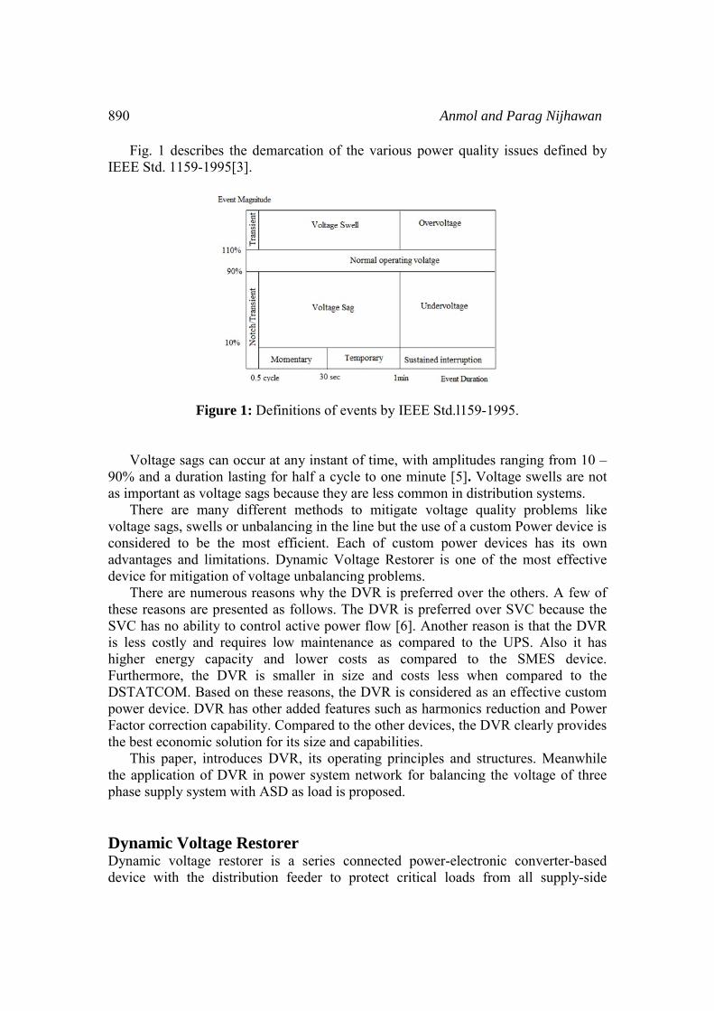
Fig. 1 describes the demarcation of the various power quality issues defined by IEEE Std. 1159-1995[3].
Figure 1: Definitions of events by IEEE Std.l159-1995. Voltage sags can occur at any instant of time, with amplitudes ranging from 10 – 90% and a duration lasting for half a cycle to one minute [5]. Voltage swells are not as important as voltage sags because they are less common in distribution systems. There are many different methods to mitigate voltage quality problems like voltage sags, swells or unbalancing in the line but the use of a custom Power device is considered to be the most efficient. Each of custom power devices has its own advantages and limitations. Dynamic Voltage Restorer is one of the most effective device for mitigation of voltage unbalancing problems. There are numerous reasons why the DVR is preferred over the others. A few of these reasons are presented as follows. The DVR is preferred over SVC because the SVC has no ability to control active power flow [6]. Another reason is that the DVR is less costly and requires low maintenance as compared to the UPS. Also it has higher energy capacity and lower costs as compared to the SMES device. Furthermore, the DVR is smaller in size and costs less when compared to the DSTATCOM. Based on these reasons, the DVR is considered as an effective custom power device. DVR has other added features such as harmonics reduction and Power Factor correction capability. Compared to the other devices, the DVR clearly provides the best economic solution for its size and capabilities. This paper, introduces DVR, its operating principles and structures. Meanwhile the application of DVR in power system network for balancing the voltage of three phase supply system with ASD as load is proposed. Dynamic Voltage Restorer Dynamic voltage restorer is a series connected power-electronic converter-based device with the distribution feeder to protect critical loads from all supply-side

Application of Dynamic Voltage Restorer 891
disturbances other than outages. It can provide the most cost effective solution to mitigate voltage imbalance by establishing the proper voltage quality level that is required by customer. When a fault happens in a distribution network, sudden voltage sag will appear on adjacent loads. DVR installed on a sensitive load, restores the line voltage to its nominal value within the response time of a few milliseconds thus avoiding any power disruption to the load. The DVR works independently of the type of fault or any event that happens in the system, provided that the whole system remains connected to the supply grid. The DVR has two modes of operation which are: standby mode and boost mode. In standby mode (VDVR=0), the booster transformer’s low voltage winding is shorted through the converter. No switching of semiconductors occurs in this mode of operation. The DVR will be most of the time in this mode. In boost mode (VDVR>0), the DVR is injecting a compensation voltage through the booster transformer due to a detection of a supply voltage disturbance The general configuration of the DVR consists of an Injection / Booster transformer, a Harmonic filter, a Voltage Source Converter (VSC), and a Control and Protection system as shown in fig 2.
Figure 2: DVR series topology.
The Injection / Booster transformer The Injection / Booster transformer is a specially designed transformer that attempts to limit the coupling of noise and transient energy from the primary side to the secondary side [7]. It connects the DVR to the distribution network via the HV-windings and transformers and couples the injected compensating voltages generated by the voltage source converters to the incoming supply voltage. In addition, the Injection / Booster transformer serves the purpose of isolating the load from the system. Harmonic Filters The main task of harmonic filter is to keep the harmonic voltage content generated by
892 Anmol and Parag Nijhawan
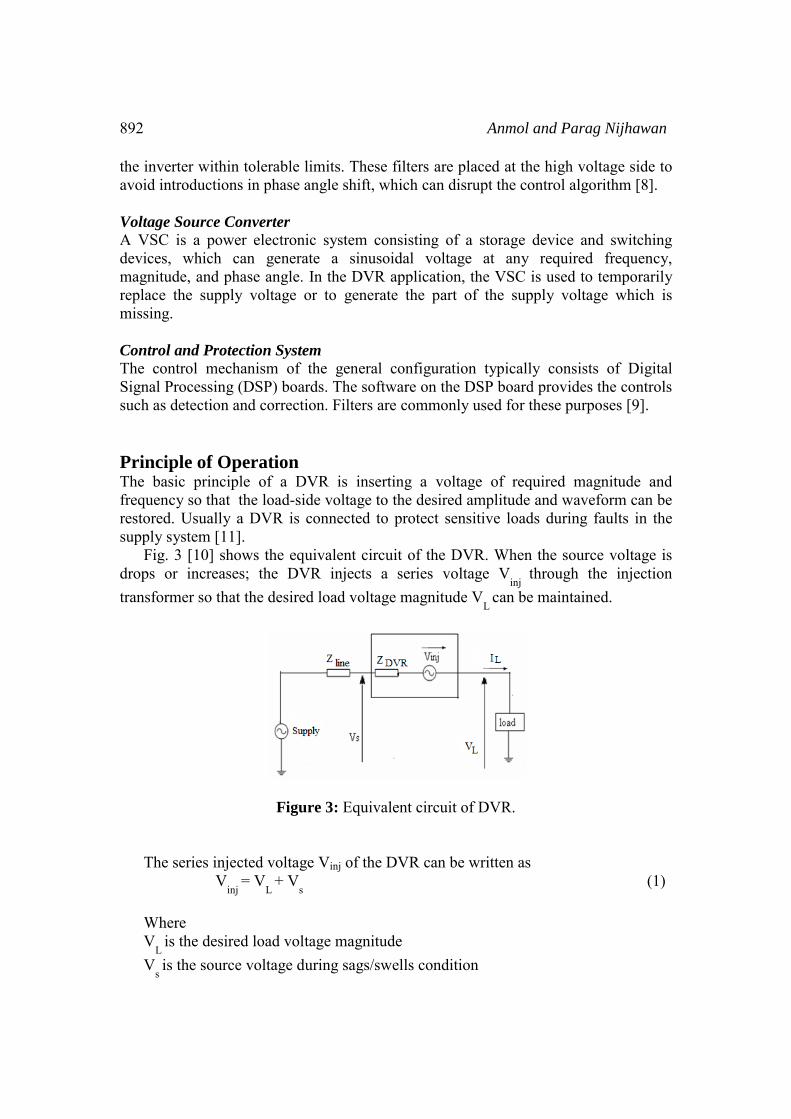
the inverter within tolerable limits. These filters are placed at the high voltage side to avoid introductions in phase angle shift, which can disrupt the control algorithm [8]. Voltage Source Converter A VSC is a power electronic system consisting of a storage device and switching devices, which can generate a sinusoidal voltage at any required frequency, magnitude, and phase angle. In the DVR application, the VSC is used to temporarily replace the supply voltage or to generate the part of the supply voltage which is missing. Control and Protection System The control mechanism of the general configuration typically consists of Digital Signal Processing (DSP) boards. The software on the DSP board provides the controls such as detection and correction. Filters are commonly used for these purposes [9]. Principle of Operation The basic principle of a DVR is inserting a voltage of required magnitude and frequency so that the load-side voltage to the desired amplitude and waveform can be restored. Usually a DVR is connected to protect sensitive loads during faults in the supply system [11]. Fig. 3 [10] shows the equivalent circuit of the DVR. When the source voltage is drops or increases; the DVR injects a series voltage V
inj through the injection
transformer so that the desired load voltage magnitude VL
can be maintained.
Figure 3: Equivalent circuit of DVR. The series injected voltage Vinj of the DVR can be written as V
inj = V
L + V
s (1)
Where V
L is the desired load voltage magnitude
Vs is the source voltage during sags/swells condition
Application of Dynamic Voltage Restorer 893
The load current IL
is given by, I
L = (( PL ± J*QL ) / VL ) (2)
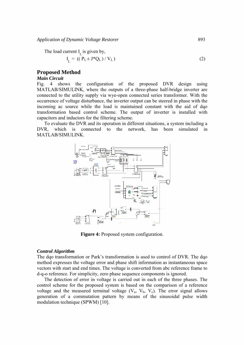
Proposed Method Main Circuit Fig. 4 shows the configuration of the proposed DVR design using MATLAB/SIMULINK, where the outputs of a three-phase half-bridge inverter are connected to the utility supply via wye-open connected series transformer. With the occurrence of voltage disturbance, the inverter output can be steered in phase with the incoming ac source while the load is maintained constant with the aid of dqo transformation based control scheme. The output of inverter is installed with capacitors and inductors for the filtering scheme. To evaluate the DVR and its operation in different situations, a system including a DVR, which is connected to the network, has been simulated in MATLAB/SIMULINK.
Figure 4: Proposed system configuration. Control Algorithm The dqo transformation or Park’s transformation is used to control of DVR. The dqo method expresses the voltage error and phase shift information as instantaneous space vectors with start and end times. The voltage is converted from abc reference frame to d-q-o reference. For simplicity, zero phase sequence components is ignored. The detection of error in voltage is carried out in each of the three phases. The control scheme for the proposed system is based on the comparison of a reference voltage and the measured terminal voltage (Va, Vb, Vc). The error signal allows generation of a commutation pattern by means of the sinusoidal pulse width modulation technique (SPWM) [10].
894 Anmol and Parag Nijhawan
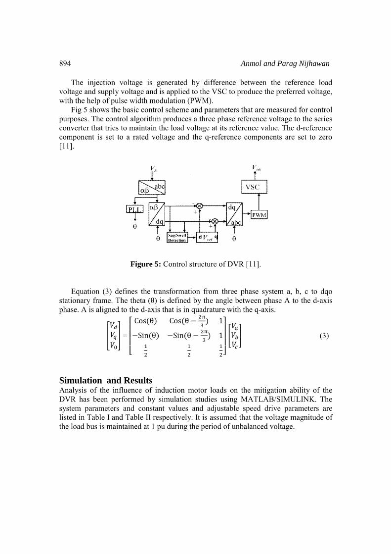
The injection voltage is generated by difference between the reference load voltage and supply voltage and is applied to the VSC to produce the preferred voltage, with the help of pulse width modulation (PWM). Fig 5 shows the basic control scheme and parameters that are measured for control purposes. The control algorithm produces a three phase reference voltage to the series converter that tries to maintain the load voltage at its reference value. The d-reference component is set to a rated voltage and the q-reference components are set to zero [11].
Figure 5: Control structure of DVR [11]. Equation (3) defines the transformation from three phase system a, b, c to dqo stationary frame. The theta (θ) is defined by the angle between phase A to the d-axis phase. A is aligned to the d-axis that is in quadrature with the q-axis.
=
Cos θ Cos θ 1
Sin θ Sin θ 1 (3)
Simulation and Results Analysis of the influence of induction motor loads on the mitigation ability of the DVR has been performed by simulation studies using MATLAB/SIMULINK. The system parameters and constant values and adjustable speed drive parameters are listed in Table I and Table II respectively. It is assumed that the voltage magnitude of the load bus is maintained at 1 pu during the period of unbalanced voltage.
Application of Dynamic Voltage Restorer 895
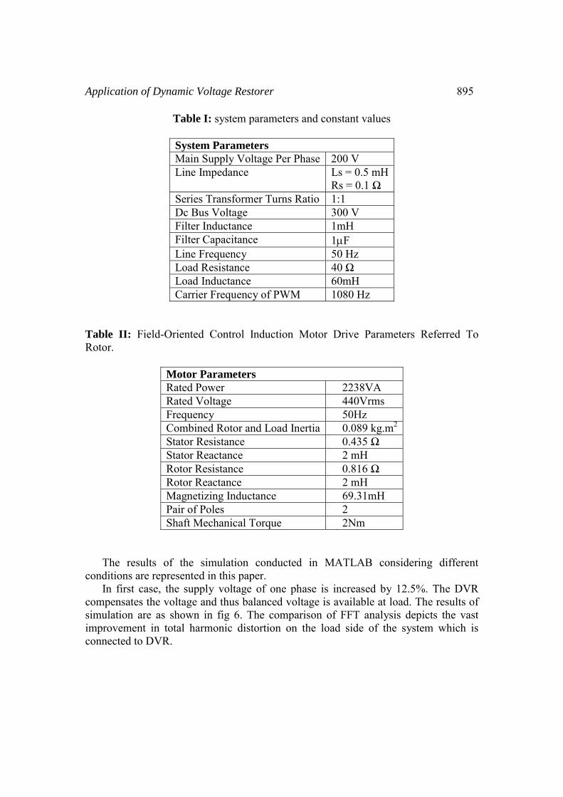
Table I: system parameters and constant values
System Parameters Main Supply Voltage Per Phase 200 V Line Impedance Ls = 0.5 mH
Rs = 0.1 Ω Series Transformer Turns Ratio 1:1 Dc Bus Voltage 300 V Filter Inductance 1mH Filter Capacitance 1μF Line Frequency 50 Hz Load Resistance 40 ΩLoad Inductance 60mH Carrier Frequency of PWM 1080 Hz
Table II: Field-Oriented Control Induction Motor Drive Parameters Referred To Rotor.
Motor Parameters Rated Power 2238VA Rated Voltage 440Vrms Frequency 50Hz Combined Rotor and Load Inertia 0.089 kg.m2
Stator Resistance 0.435 Ω Stator Reactance 2 mH Rotor Resistance 0.816 Ω Rotor Reactance 2 mH Magnetizing Inductance 69.31mH Pair of Poles 2 Shaft Mechanical Torque 2Nm
The results of the simulation conducted in MATLAB considering different conditions are represented in this paper. In first case, the supply voltage of one phase is increased by 12.5%. The DVR compensates the voltage and thus balanced voltage is available at load. The results of simulation are as shown in fig 6. The comparison of FFT analysis depicts the vast improvement in total harmonic distortion on the load side of the system which is connected to DVR.

896
Figure 6: (a) Source voltadistortion on the load withload with DVR In second case, the so0.001Ω. The results are considerable improvement
Anmol and Pa
age (pu) (b) Voltage at load (c) Percentage ofhout DVR (d) Percentage of total harmonic d
ource resistance of line impedance is alteredas shown in fig 7. The voltage at load i
t of total harmonic distortion is seen.
arag Nijhawan
f total harmonic distortion on the
d from 0.1Ω to s regained and
Application of Dynamic V
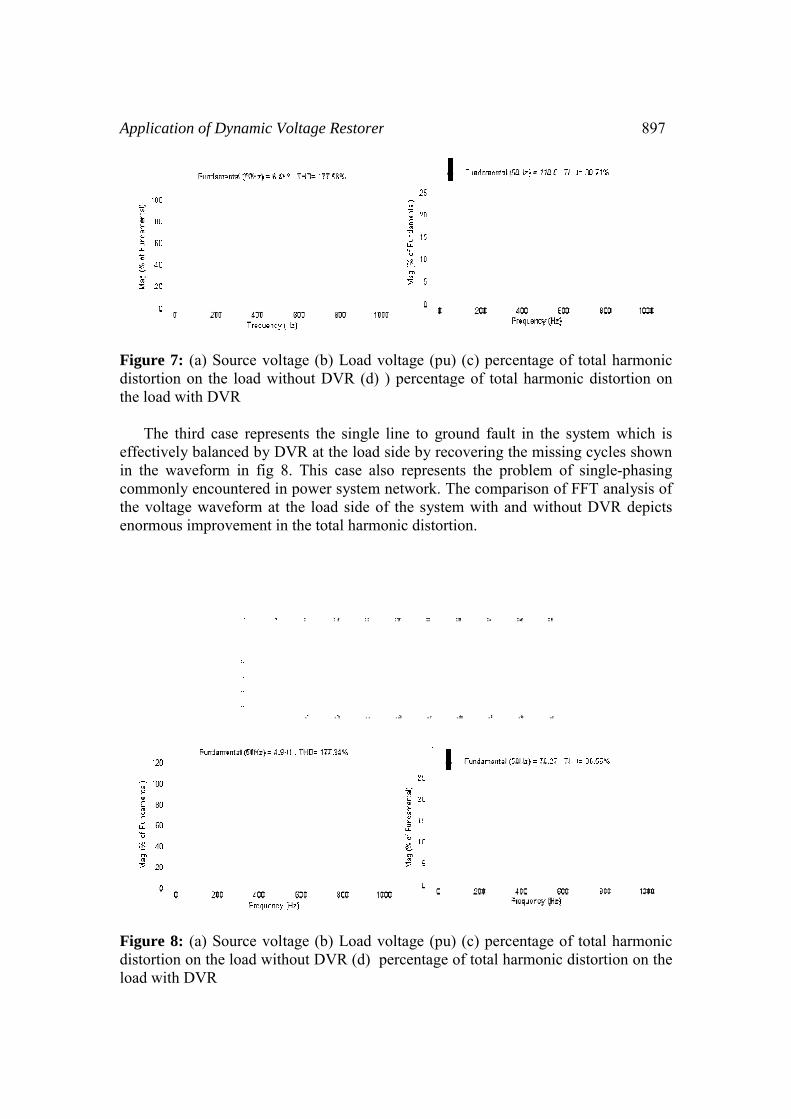
Figure 7: (a) Source voltdistortion on the load witthe load with DVR The third case represeeffectively balanced by DVin the waveform in fig 8commonly encountered inthe voltage waveform at tenormous improvement in
Figure 8: (a) Source voltdistortion on the load withload with DVR
Voltage Restorer
tage (b) Load voltage (pu) (c) percentage ofthout DVR (d) ) percentage of total harmon
ents the single line to ground fault in the syVR at the load side by recovering the missin
8. This case also represents the problem ofn power system network. The comparison of Fthe load side of the system with and withou
n the total harmonic distortion.
tage (b) Load voltage (pu) (c) percentage ofhout DVR (d) percentage of total harmonic d
897
f total harmonic ic distortion on
ystem which is ng cycles shown f single-phasing FFT analysis of ut DVR depicts
f total harmonic distortion on the

898 Anmol and Parag Nijhawan
Conclusion The modeling and simulation of a DVR using MATLAB/SIMULINK has been presented. This paper proposed a low voltage dynamic voltage restorer connected to adjustable speed drive load. The dqo control algorithm which is a scaled error of the between source side of the DVR and its reference was implemented to restore the missing cycles of voltage. The proposed method can compensate for most of the voltage faults such as harmonics and any kind of voltage unbalance on the supply networks. References
[1] Pierre Giroux, Gilbert Sybille, Hoang Le-Huy “Modeling and Simulation of a Distribution STATCOM using Simulink’s Power System Blockset”, IECON; 01: the 27th Annual Conference of the IEEE Industrial Electronics Society, pp. 990 -994.
[2] Thomas E. Grebe, “Application of Distribution System Capacitor Banks And Their Impact On Power Quality”, IEEE Transactions On Industry Applications, vol. 32, no. 3, May/June 1996, pp 714-719.
[3] Toshifiimi Ise, Yusuke Hayashi, and Kiichiro Tsuji, "Definitions of power quality levels and the simplest approach for unbundled power quality services," IEEE Proc. in the Ninth International Conference on Harmonics and Quality of Power, Orlando, FL, vol. 2, oct. 2000, pp. 385-390.
[4] C. Sankaran, “Power Quality”, CRC Press LLC, 2002. [5] M.Arun Bhaskar, Dr.S.S.Dash, C.Subramani, M.Jagdeesh Kumar, P.R.Giresh
and M.Varun Kumar, “Voltage Quality Improvement Using DVR”, IEEE International Conference on Recent Trends in Information, Telecommunication and Computing, 2010, pp378-380.
[6] Chellali Benachaiba, Brahim Ferdi, “Voltage Quality Improvement Using DVR”, Electrical Power Quality and Utilisation, journal no. 1, vol. XIV, 2008, pp39-46 .
[7] Hyosung Kim, Jang-Hwan Kim, Seung-Ki Sul, “A Design Consideration Of Output Filters For Dynamic Voltage Restorers”, 35th Annual IEEE Power Electronics Specialists Conference, 2004, pp 4268-4272.
[8] K.Chandrasekaran, P.A.Venkatachalam, Mohd Noh Karsiti, “Dynamic Voltage Restorer As A Sag Mitigator And Harmonic Restorer”, IEEE International Conference on Sustainable Energy Technologies, 2008, pp 904-909.
[9] Mahesh Singh, Vaibhav Tiwari, “Modeling analysis and solution of Power Quality Problems”, Available: http://eeeic.org/proc/papers/50.pdf.
[10] Rosli Omar And Nasrudin Abd Rahim, “Modeling and Simulation for Voltage Sags/Swells Mitigation Using Dynamic Voltage Restorer (DVR)”, IEEE Australasian Universities Power Engineering Conference, 2008, Paper P-027.
[11] Arindam Ghosh, and Gerard Ledwich, “Compensation of Distribution System Voltage Using DVR”, IEEE Transactions On Power Delivery, vol. 17, no. 4, October 2002, pp.1030-1036.