application note et9300 service 134 ethercat technology group (etg) headquarters 134 6 application...
TRANSCRIPT
Version 1.8 Date: 2017-11-14
Application Note ET9300 (EtherCAT Slave Stack Code)

II Application Note ET9300
LEGAL NOTICE
Trademarks Beckhoff®, TwinCAT®, EtherCAT®, Safety over EtherCAT®, TwinSAFE® and XFC® are registered trademarks of and licensed by Beckhoff Automation GmbH. Other designations used in this publication may be trademarks whose use by third parties for their own purposes could violate the rights of the owners. Patent Pending The EtherCAT Technology is covered, including but not limited to the following German patent applications and patents: DE10304637, DE102004044764, DE102005009224, DE102007017835 with corresponding applications or registrations in various other countries. Disclaimer The documentation has been prepared with care. The products described are, however, constantly under development. For that reason the documentation is not in every case checked for consistency with performance data, standards or other characteristics. In the event that it contains technical or editorial errors, we retain the right to make alterations at any time and without warning. No claims for the modification of products that have already been supplied may be made on the basis of the data, diagrams and descriptions in this documentation. Copyright © Beckhoff Automation GmbH The reproduction, distribution and utilization of this document as well as the communication of its contents to others without express authorization are prohibited. Offenders will be held liable for the payment of damages. All rights reserved in the event of the grant of a patent, utility model or design.
Application Note ET9300 1
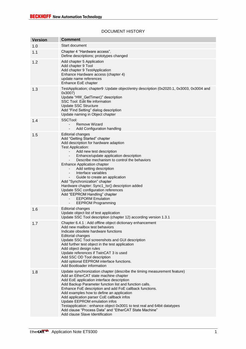
DOCUMENT HISTORY
Version Comment
1.0 Start document
1.1 Chapter 4 “Hardware access”. Define descriptions; prototypes changed
1.2 Add chapter 5 Application Add chapter 9 Tool Add chapter 9 TestApplication Enhance Hardware access (chapter 4) update name references Enhance EoE chapter
1.3 TestApplication; chapter9 :Update object/entry description (0x2020.1, 0x3003, 0x3004 and 0x3007) Update “HW_GetTimer()” description SSC Tool: Edit file information Update SSC Structure Add “Find Setting” dialog description Update naming in Object chapter
1.4 SSCTool: - Remove Wizard - Add Configuration handling
1.5 Editorial changes Add “Getting Started” chapter Add description for hardware adaption Test Application:
- Add new test description - Enhance/update application description - Describe mechanism to control the behaviors
Enhance Application chapter - Add setting description - Interface variables - Guide to create an application
Add “Synchronization” chapter Hardware chapter: Sync1_Isr() description added Update SSC configuration references Add “EEPROM Handling” chapter
- EEPORM Emulation - EEPROM Programming
1.6 Editorial changes Update object list of test application Update SSC Tool description (chapter 12) according version 1.3.1
1.7 Chapter 6.4.1 : Add offline object dictionary enhancement Add new mailbox test behaviors Indicate obsolete hardware functions Editorial changes Update SSC Tool screenshots and GUI description Add further test object in the test application Add object design rules Update references if TwinCAT 3 is used Add SSC OD Tool description Add optional EEPROM interface functions. Add Bootloader information
1.8 Update synchronization chapter (describe the timing measurement feature) Add an EtherCAT state machine chapter Add EoE application interface description Add Backup Parameter function list and function calls. Enhance FoE description and add FoE callback functions. Add examples how to define an application Add application parser CoE callback infos Update EEPROM emulation infos Testapplication : enhance object 0x3001 to test real and 64bit datatypes Add clause “Process Data” and “EtherCAT State Machine” Add clause Slave Identification

2 Application Note ET9300
NOTE: This document makes no claim to be complete regarding to the containing topics or the Slave Stack Code. For annotations or comments to this document please send an email to [email protected].

Application Note ET9300 3
CONTENTS
1 References 9
2 Terms, Definition, Abbreviation 10
2.1 Abbreviation 10
3 Getting Started 11
3.1 SSC Tool 11
3.2 Default SSC files 11
4 Code Structure 13
4.1 Execution structure 14
4.2 Interrupt handling 15
4.3 Process data handling 16
5 Hardware Access 18
5.1 Interrupt Handler 22
5.2 Interface Functions/Macros 23
5.2.1 Generic 23
5.2.2 Read Access 26
5.2.3 Write Access 30
6 Application 33
6.1 SSC Functions 33
6.2 Interface Functions 35
6.2.1 Generic 35
6.2.2 EtherCAT State Machine 37
6.2.3 Process data handling 39
6.2.4 Mailbox handling 39
6.3 Interface Variables 44
6.4 Create an Application 45
6.4.1 Examples 45
7 Objects 56
7.1 Structure/Alignment Rules 56
7.2 Define local memory 57
7.3 Entry descriptions 57
7.4 Object name 58
7.5 Object description 59
7.6 Index Ranges 60
7.7 Implementation examples 61
7.7.1 Usage of Object Deftype ENUM 61
8 Mailbox 63
8.1 CoE (CAN application protocol over EtherCAT) 63
8.1.1 Backup Parameter support 63
8.2 FoE (File Transfer over EtherCAT) 65
8.2.1 Testing FoE 65

4 Application Note ET9300
8.3 EoE (Ethernet over EtherCAT) 66
8.3.1 Implementation 66
8.3.2 EoE Examples 68
9 Synchronization 74
9.1 Supported Sync Modes 74
9.1.1 FreeRun 76
9.1.2 SyncManager 76
9.1.3 SyncManager/Sync0 77
9.1.4 SyncManager/Sync0/Sync1 77
9.1.5 Sync0 78
9.1.6 Sync0/Sync1 78
9.1.7 Subordinated Cycles 78
9.2 Synchronization Timings 79
10 CiA402 drive profile 81
10.1 Objects 81
10.2 State machine 82
10.3 Operation modes 84
10.4 TwinCAT setup 85
10.4.1 Automatic network setup 86
10.4.2 Manual network setup 87
10.4.3 NC parameter setup 89
11 TestApplication 91
11.1 Slave Behavior Control 91
11.1.1 Test Control Object 91
11.1.2 User RAM 0xF80:0xF83 92
11.2 ESM Tests (0x2000 – 0x200F) 92
11.3 Mailbox Tests (0x2010 – 0x201F) 93
11.4 CoE Tests (0x2020 – 0x202F) 93
11.5 FoE Tests (0x2030 – 0x203F) 94
11.6 Generic Objects 94
12 SSC Tool 99
12.1 Default Startup Dialogs 99
12.2 Main User Interface Elements 100
12.2.1 Tool Bar 100
12.2.2 Windows 104
12.3 Create Files 105
12.4 Local SSC Update 106
12.5 Project Update 107
12.6 Import Configurations 107
13 OD Tool 109
13.1 Console application 109
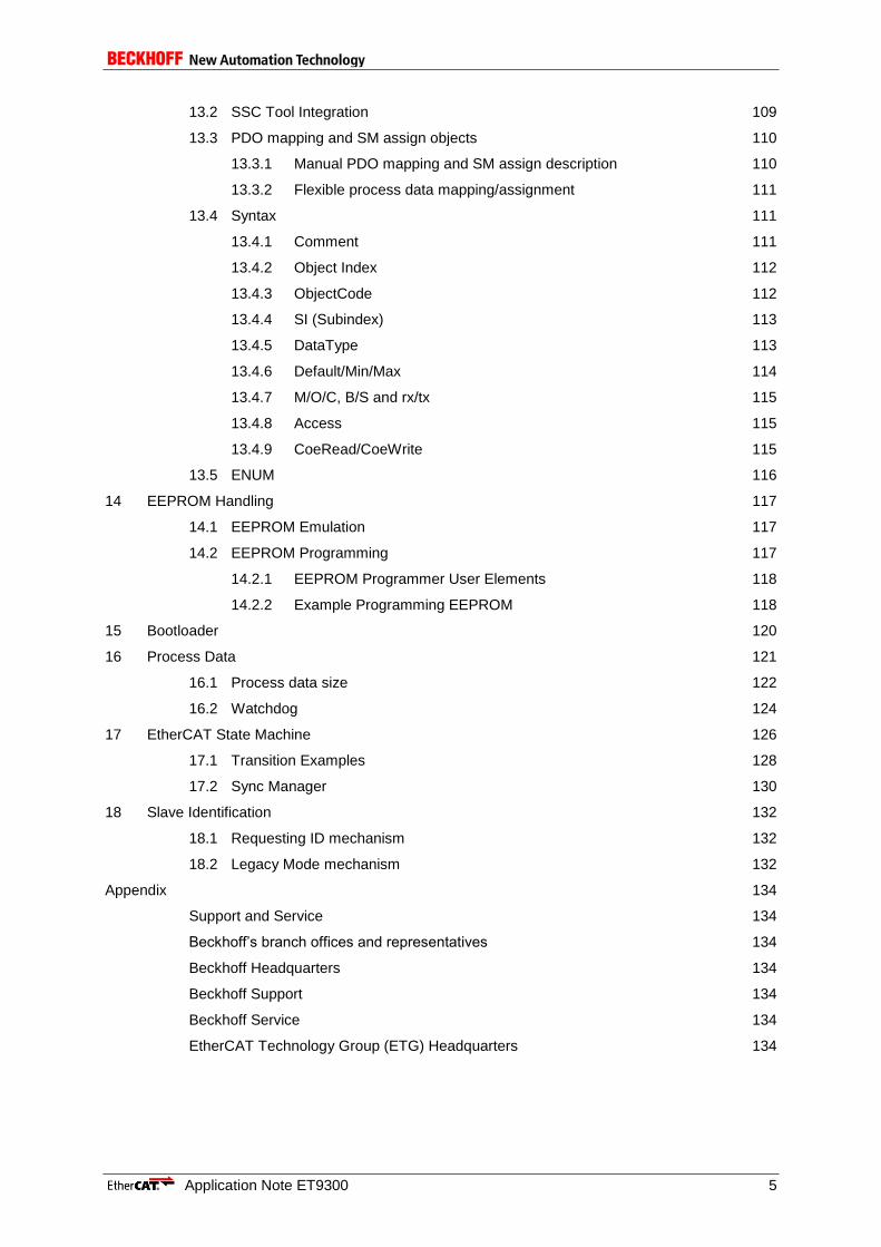
Application Note ET9300 5
13.2 SSC Tool Integration 109
13.3 PDO mapping and SM assign objects 110
13.3.1 Manual PDO mapping and SM assign description 110
13.3.2 Flexible process data mapping/assignment 111
13.4 Syntax 111
13.4.1 Comment 111
13.4.2 Object Index 112
13.4.3 ObjectCode 112
13.4.4 SI (Subindex) 113
13.4.5 DataType 113
13.4.6 Default/Min/Max 114
13.4.7 M/O/C, B/S and rx/tx 115
13.4.8 Access 115
13.4.9 CoeRead/CoeWrite 115
13.5 ENUM 116
14 EEPROM Handling 117
14.1 EEPROM Emulation 117
14.2 EEPROM Programming 117
14.2.1 EEPROM Programmer User Elements 118
14.2.2 Example Programming EEPROM 118
15 Bootloader 120
16 Process Data 121
16.1 Process data size 122
16.2 Watchdog 124
17 EtherCAT State Machine 126
17.1 Transition Examples 128
17.2 Sync Manager 130
18 Slave Identification 132
18.1 Requesting ID mechanism 132
18.2 Legacy Mode mechanism 132
Appendix 134
Support and Service 134
Beckhoff’s branch offices and representatives 134
Beckhoff Headquarters 134
Beckhoff Support 134
Beckhoff Service 134
EtherCAT Technology Group (ETG) Headquarters 134

6 Application Note ET9300
FIGURES
Figure 1: EtherCAT Slave Stack Code .................................................................................................. 13 Figure 2: File-Stack Association ............................................................................................................ 14 Figure 3: Basic SSC execution structure ............................................................................................... 14 Figure 4: SSC MainLoop execution ....................................................................................................... 15 Figure 5: ESC Interrupts basics ............................................................................................................ 15 Figure 6: EL9800 Application Output Mapping ..................................................................................... 16 Figure 7: EL9800 Application Input Mapping ........................................................................................ 17 Figure 8: Hardware Functions Schema ................................................................................................. 22 Figure 9: Application Functions Schema ............................................................................................... 33 Figure 10: Application example ............................................................................................................. 45 Figure 11: RxPdo data of an EtherCAT slave ....................................................................................... 52 Figure 12: Object definition schema ...................................................................................................... 56 Figure 13: EL9800 Application object ranges........................................................................................ 61 Figure 14: Backup parameter Initialization ............................................................................................ 64 Figure 15: Restore the default backup parameter values ..................................................................... 65 Figure 16: Store backup parameters ..................................................................................................... 65 Figure 17: Send EoE datagram ............................................................................................................. 67 Figure 18: Receive EoE datagram ........................................................................................................ 68 Figure 19: EoE Example 1 (Schema) .................................................................................................... 69 Figure 20: Network card settings ........................................................................................................... 70 Figure 21: Access EtherCAT Slave Settings ......................................................................................... 70 Figure 22: EoE EtherCAT Slave Settings .............................................................................................. 71 Figure 23: Ping Command Window ....................................................................................................... 71 Figure 24: EoE Example 2 (Schema) .................................................................................................... 72 Figure 25: Enable IP Routing WinXP .................................................................................................... 72 Figure 26: Enable IP Routing WinCE .................................................................................................... 73 Figure 27: ESC Interrupt Signals ........................................................................................................... 74 Figure 28: Free Run .............................................................................................................................. 76 Figure 29: SyncManager Synchronization ............................................................................................ 76 Figure 30: SM/Sync0 Synchronization .................................................................................................. 77 Figure 31: SM/Sync0/Sync1 Synchronization ....................................................................................... 77 Figure 32: Sync0 Synchronization ......................................................................................................... 78 Figure 33: Sync0/Sync1 Synchronization .............................................................................................. 78 Figure 34: Subordinated Cycles ............................................................................................................ 79 Figure 35: CiA402 state transitions and option codes ........................................................................... 83 Figure 36: Axis configuration ................................................................................................................. 85 Figure 37: Set device variable without PLC link .................................................................................... 86 Figure 38: Scan for new EtherCAT devices with TwinCAT 2 ................................................................ 86 Figure 39: Scan for new EtherCAT devices with TwinCAT 3 ................................................................ 87 Figure 40: TwinCAT 2 CiA402 axis setup ............................................................................................. 87 Figure 41: TwinCAT 3 CiA402 axis setup ............................................................................................. 88 Figure 42: Add CiA402 device ............................................................................................................... 88 Figure 43: Link multiple variables .......................................................................................................... 89 Figure 44: Encoder scaling .................................................................................................................... 90 Figure 45: Velocity scaling..................................................................................................................... 90 Figure 46: Configurator Main User Interface ......................................................................................... 99 Figure 47: Configurator File Menu ....................................................................................................... 100 Figure 48: Create New Project ............................................................................................................ 100 Figure 49: Configurator Project Menu ................................................................................................. 100 Figure 50: Find Setting Dialog ............................................................................................................. 101 Figure 51: Tool Menu .......................................................................................................................... 101 Figure 52: Tool Options ....................................................................................................................... 102 Figure 53: Configurator Locked Define ............................................................................................... 102 Figure 54: Configurations List.............................................................................................................. 103 Figure 55: Configurator Help Menu ..................................................................................................... 103 Figure 56: Configurator Project Information ........................................................................................ 104 Figure 57: Configurator File Context Menu ......................................................................................... 104 Figure 58: Configurator Slave Settings ............................................................................................... 105 Figure 59: Configurator Create Files ................................................................................................... 106 Figure 60: Configurator Slave Stack Code Update ............................................................................. 106

Application Note ET9300 7
Figure 61: Configurator Project Update Dialog ................................................................................... 107 Figure 62: New Project | Import Configuration .................................................................................... 108 Figure 63: Options | Import Configuration ........................................................................................... 108 Figure 64: SSC OD Tool workflow ...................................................................................................... 109 Figure 65: Excel application definition example .................................................................................. 109 Figure 66: Maunal definition of PDO mapping and SM assign objects ............................................... 110 Figure 67: Description of a flexible PDO assignment .......................................................................... 111 Figure 68: TwinCAT slave config PDO assignment ............................................................................ 111 Figure 69: Application file comment .................................................................................................... 111 Figure 70: ObjectCode Examples ....................................................................................................... 112 Figure 71: SubIndex definition examples ............................................................................................ 113 Figure 72: Entry DataType example .................................................................................................... 114 Figure 73: Default data example ......................................................................................................... 115 Figure 74: CoeRead/CoeWrite example ............................................................................................. 115 Figure 75: CoeRead/CoeWrite example function body ....................................................................... 116 Figure 76: EEPROM Programming Tool ............................................................................................. 118 Figure 77: EEPROM Programmer | File .............................................................................................. 118 Figure 78: EEPROM Programmer | Slaves ......................................................................................... 118 Figure 79: EEPROM Programmer | List Elements .............................................................................. 118 Figure 80: Output mapping example ................................................................................................... 121 Figure 81: Input mapping example ...................................................................................................... 122 Figure 82: Calculate process data size example ................................................................................ 123 Figure 83: Process data watchdog defines ......................................................................................... 124 Figure 84: ESC process data watchdog configuration ........................................................................ 125 Figure 85: EtherCAT state ................................................................................................................... 126 Figure 86: ESM progress ..................................................................................................................... 127 Figure 87: Accepted ESM example ..................................................................................................... 129 Figure 88: Rejected ESM example ...................................................................................................... 130 Figure 89: Sync Manager settings in the SSC Tool ............................................................................ 131 Figure 90: Legacy ID handling ............................................................................................................ 132
8 Application Note ET9300
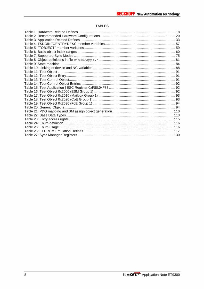
TABLES
Table 1: Hardware Related Defines ...................................................................................................... 18 Table 2: Recommended Hardware Configurations ............................................................................... 20 Table 3: Application Related Defines .................................................................................................... 33 Table 4: TSDOINFOENTRYDESC member variables .......................................................................... 57 Table 5: "TOBJECT" member variables ................................................................................................ 59 Table 6: Basic object index ranges ....................................................................................................... 60 Table 7: Supported Sync Modes ........................................................................................................... 75
Table 8: Object definitions in file cia402appl.h ................................................................................ 81
Table 9: State machine .......................................................................................................................... 84 Table 10: Linking of device and NC variables ....................................................................................... 88 Table 11: Test Object ............................................................................................................................ 91 Table 12: Test Object Entry ................................................................................................................... 91 Table 13: Test Control Object................................................................................................................ 91 Table 14: Test Control Object Entries ................................................................................................... 92 Table 15: Test Application | ESC Register 0xF80:0xF83 ...................................................................... 92 Table 16: Test Object 0x2000 (ESM Group 1) ...................................................................................... 92 Table 17: Test Object 0x2010 (Mailbox Group 1) ................................................................................. 93 Table 18: Test Object 0x2020 (CoE Group 1) ....................................................................................... 93 Table 19: Test Object 0x2030 (FoE Group 1) ....................................................................................... 94 Table 20: Generic Objects ..................................................................................................................... 94 Table 21: PDO mapping and SM assign object generation ................................................................ 110 Table 22: Base Data Types ................................................................................................................. 113 Table 23: Entry access rights .............................................................................................................. 115 Table 24: Enum definition .................................................................................................................... 116 Table 25: Enum usage ........................................................................................................................ 116 Table 26: EEPROM Emulation Defines ............................................................................................... 117 Table 27: Sync Manager Registers ..................................................................................................... 130
Application Note ET9300 9
1 References
[1] ETG.6010 Implementation Guideline for the CiA402 Drive Profile (www.ethercat.org/ETG6010)
[2] ETG.1000 part 6 Application Layer protocol specification (www.ethercat.org/ETG1000) [3] Application Note EL9800 [4] ETG.2000 Slave Information Specification (www.ethercat.org/ETG2000) [5] ETG 5001 Modular Device Profile Specification (www.ethercat.org/ETG5001) [6] ET1100 Datasheet [7] ETG.1020 Protocol Enhancements (www.ethercat.org/ETG1020) [8] EtherCAT Slave Quick Design Guide
(http://download.beckhoff.com/download/Document/EtherCAT/Development_products/EtherCAT_Slave_Design_Quick_Guide.pdf)
10 Application Note ET9300
2 Terms, Definition, Abbreviation
Base Datatypes -- CoE Datatypes defined in ETG.1000.6
Entry – in conclusion with object single element,
in conclusion with object dictionary the objects
Subindex -- describes a single element (entry) of an object
Object dictionary – the object dictionary is a list of objects. Within this list each object is uniquely identified by an (object) index.
2.1 Abbreviation
Abbreviation Description AL Application Layer CoE CANopen application profile over EtherCAT
CANopen™ is a registered trademark of CAN in Automation e.V., Nuremberg, Germany
CiA402 CANopen™ Drive Profile specified in IEC 61800-7-201; CANopen™ and CiA™ are registered trademarks of CAN in Automation e.V., Nuremberg, Germany
csp cycle synchronous position csv cycle synchronous velocity DC Distributed Clocks EoE Ethernet over EtherCAT ESC EtherCAT Slave Controller FoE File Transfer over EtherCAT GPO General Purpose Output NC Numeric Control PDI Process data interface PDO Process Data Object PLC Programmable Logic Controller SI SubIndex SII Slave Information Interface SM Sync Manager SPI Serial Peripheral Interface SSC Slave Stack Code
Application Note ET9300 11
3 Getting Started
This is a step by step instruction how to start the EtherCAT slave development with the Slave Stack Code (SSC). There is also an EtherCAT Slave Design Quick Guide available in the downloaded SSC archive. In general two possibilities are available either using the SSC Tool (3.1 SSC Tool) or the default SSC files (3.2 Default SSC files).
Further information regarding the SSC are also available in the ETG developers forum.
3.1 SSC Tool
1. Download the Slave Stack Code here. NOTE: To download the SSC the ETG member login and an EtherCAT Vendor ID is required. If you are not an ETG member click here or if you do not have an EtherCAT Vendor ID click here.
2. Unzip the downloaded archive.
3. Install "EtherCAT Slave Stack Code Tool.msi".
4. Start the SSC Tool (Start -> Program Files -> EtherCAT Slave Stack Code Tool -> SSC Tool).
5. Acknowledge the usage agreement.
6. Enter your Vendor ID and company name.
7. Create a new project (File -> New)
8. Select ...
a. the default SSC configuration.
b. a custom platform/application configuration. If a configuration file is available it can also be added via the "Import" button.
NOTE: If the SSC shall be executed on a third party platform, e.g. Texas Instruments AM335x or Renesas R-IN32M3, it is recommended to use the corresponding configuration.
9. If the default SSC configuration was selected the hardware defines should be adapted according to the target platform (Project Navigation -> "Hardware").
10. Select the slave application (Project Navigation -> "Application").
11. Save the project (File -> Save).
12. If Doxygen is installed a source code documentation can be created automatically (Tool -> Options -> Create Files -> Create Documentation).
13. Create the slave files (Project -> Create new Slave Files).
14. Click "Start".
15. Create a slave project with the target platform specific IDE, import the generated source files and run the slave binary. For further details see the IDE/SDK documentation of the platform vendor.
16. Make the ESI file available in the ESI cache of the EtherCAT configuration tool/master.
17. Connect the slave platform and the EtherCAT configuration tool and create a network.
18. Run the network configuration.
3.2 Default SSC files
1. Download the Slave Stack Code here. NOTE: To download the SSC the ETG member login and an EtherCAT Vendor ID is required. If you are not an ETG member click here or if you do not have an EtherCAT Vendor ID click here.
2. Unzip the downloaded archive.
3. Create a slave project with the target platform specific IDE, import the SSC files and run the slave binary. For further details see the IDE/SDK documentation of the platform vendor.
12 Application Note ET9300
4. Adapt the defines in ecat_def.h to the target platform and application.
5. Create an ESI file according to the defines in step 4.
6. Make the ESI file available in the ESI cache of the EtherCAT configuration tool/master.
7. Connect the slave platform and the EtherCAT configuration tool and create a network.
8. Run the network configuration.

Application Note ET9300 13
4 Code Structure
The EtherCAT slave stack as seen in Figure 1 consists of three parts:
- PDI/Hardware abstraction
o Hardware specific, need to be implemented according the platform/PDI
o Ready to used samples/implementations are available for certain platforms
o The interface to the generic stack is described in chapter 5.
- Generic EtherCAT stack
o Implements the full EtherCAT statemachine, mailbox communication and generic process data exchange
o No further implementation need (only configured via the SSC Tool, chapter 12 or defines)
- User application
o Need to be implemented (a table-based code generator for the application is available, chapter 13.
o Ready to uses samples are available
o The interface to the generic stack is described in chapter 6.
PDI and hardware abstraction
EtherCAT
State
MachineMailbox
Process
data
Ao
E
Co
E
Fo
E
So
E
Vo
E
Eo
E
Application
e.g. CiA402 Drive Profile
Mailbox Process data
Register ESC address space (DPRAM)0x0000 0x1000
UserApplication
GenericEtherCAT stack
Hardware
access
EtherCAT Slave
Controller (extract)
Application function set
Hardware function set
Figure 1: EtherCAT Slave Stack Code
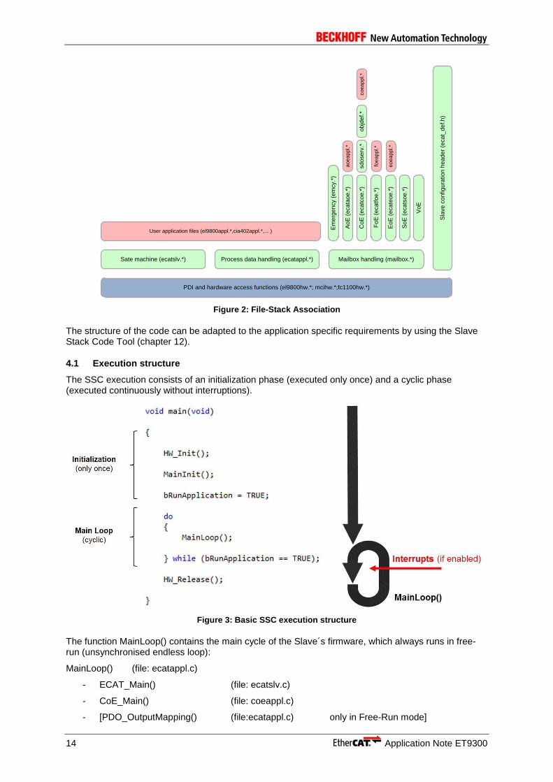
Figure 2 shows the association between the Slave Stack Code layers and the source files.
14 Application Note ET9300
User application files (el9800appl.*,cia402appl.*,... )
PDI and hardware access functions (el9800hw.*; mcihw.*;fc1100hw.*)
Sate machine (ecatslv.*)
Sla
ve
co
nfig
ura
tio
n h
ea
de
r (e
ca
t_d
ef.h
)
Mailbox handling (mailbox.*)Process data handling (ecatappl.*)
Em
erg
en
cy (
em
cy.*
)
Ao
E (
eca
tao
e.*
)
Co
E (
eca
tco
e.*
)
Fo
E (
eca
tfo
e.*
)
So
E (
eca
tso
e.*
)
Vo
E
sd
ose
rv.*
ob
jde
f.*
ao
ea
pp
l.*
co
ea
pp
l.*
foe
ap
pl.*
Eo
E (
eca
teo
e.*
)e
oe
ap
pl.*
Figure 2: File-Stack Association
The structure of the code can be adapted to the application specific requirements by using the Slave Stack Code Tool (chapter 12).
4.1 Execution structure
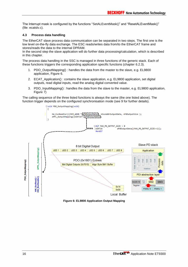
The SSC execution consists of an initialization phase (executed only once) and a cyclic phase (executed continuously without interruptions).
Figure 3: Basic SSC execution structure
The function MainLoop() contains the main cycle of the Slave´s firmware, which always runs in free-run (unsynchronised endless loop):
MainLoop() (file: ecatappl.c)
- ECAT_Main() (file: ecatslv.c)
- CoE_Main() (file: coeappl.c)
- [PDO_OutputMapping() (file:ecatappl.c) only in Free-Run mode]

Application Note ET9300 15
- [ECAT_Application() (file: ecatappl.c) only in Free-Run mode]
- [PDO_InputMapping() (file: ecatappl.c) only in Free-Run mode]
Figure 4: SSC MainLoop execution
4.2 Interrupt handling
The SSC makes use of up to four interrupts. The corresponding interrupt handler of the generic stack are listed in chapter 5.1.
1. Timer Interrupt : platform internal 1ms timer to set the EtherCAT LEDs and watchdogs. If no timer interrupt is configured (ECAT_TIMER_INT = 0) the required 1ms cycle is based on the mainloop an platform internal counter.
2. Sync0 : Process data handling and application synchronization with Distributed Clocks (DC), see chapter 9.
3. Sync1 : Process data handling and application synchronization with Distributed Clocks (DC), see chapter 9.
4. PDI Interrupt: Process data handling and application synchronization with, see chapter 9.
The events which trigger the PDI interrupt can be configured by the slave application (Figure 5).
Figure 5: ESC Interrupts basics
The only interrupt sources which are actually handled by PDI ISR in the SSC, and therefore not filtered by the AL Event Mask, are the Process Data SyncManager interrupts, and specifically: SM2 if Process Data Outputs are configured for the Slave, otherwise SM3. All the other possible sources (included all other SyncManagers) can be directly polled in Register 0x0220.
16 Application Note ET9300
The Interrupt mask is configured by the functions “SetALEventMask()” and “ResetALEventMask()” (file: ecatslv.c).
4.3 Process data handling
The EtherCAT slave process data communication can be separated in two steps. The first one is the low level on-the-fly data exchange. The ESC reads/writes data from/to the EtherCAT frame and stores/reads the data to the internal DPRAM. In the second step the slave application will do further data processing/calculation, which is described in this chapter.
The process data handling in the SSC is managed in three functions of the generic stack. Each of these functions triggers the corresponding application specific functions (chapter 6.2.3).
1. PDO_OutputMapping() : handles the data from the master to the slave, e.g. EL9800 application, Figure 6.
2. ECAT_Application() : contains the slave application, e.g. EL9800 application, set digital outputs, read digital inputs, read the analog digital converted value.
3. PDO_InputMapping() : handles the data from the slave to the master, e.g. EL9800 application, Figure 7)
The calling sequence of the three listed functions is always the same (the one listed above). The function trigger depends on the configured synchronisation mode (see 9 for further details).
Figure 6: EL9800 Application Output Mapping

Application Note ET9300 17
Figure 7: EL9800 Application Input Mapping
18 Application Note ET9300
5 Hardware Access
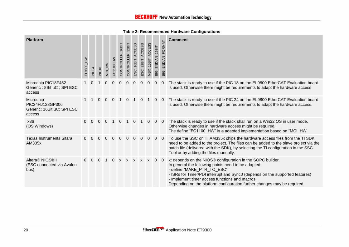
The Slave Stack Code is executable on multiple platforms and controller architectures. This chapter describes the available hardware implementations/defines and how to implement a new user specific hardware access. To support multiple hardware architectures the SSC includes multiple defines to fulfill the specific hardware requirements. Table 1: Hardware Related includes a list of the defined hardware defines (located in ecat_def.h or in the SSC Tool).
Table 1: Hardware Related Defines
Define Description
EL9800_HW Hardware access if the slave code is executed on the PIC mounted on EL9800 EtherCAT Evaluation Kit from Beckhoff Automation GmbH. It includes PIC initialization and ESC access via SPI. This configuration could also be used if the SSC needs to be adapted to any other 8 or 16Bit µC which accesses the ESC via SPI.
PIC24 Activates the configuration for the Microchip PCI24HJ128GP306 µC which is mounted on the EL9800 EtherCAT Evaluation board since Revision 4A. This define shall only active if define “EL9800_HW” is also set.
PIC18 Activates the configuration for the Microchip PIC18F452 µC which is mounted on the EL9800 EtherCAT Evaluation board, Revision 2. This define shall only active if define “EL9800_HW” is also set.
MCI_HW Generic MCI implementation. Can be used if any kind of memory interface face is used to access the ESC.
FC1100_HW Specific hardware implementation for the FC1100 PCI EtherCAT slave card from Beckhoff. Used on Win32 operating system.
CONTROLLER_16BIT This define shall be used if the slave code is built for a 16Bit µC.
CONTROLLER_32BIT This define shall be used if the slave code is built for a 32Bit µC.
ESC_16BIT_ACCESS If this define is set, then only 16Bit aligned accesses will be performed on the ESC.
ESC_32BIT_ACCESS If this define is set, then only 32Bit aligned accesses will be performed on the ESC.
MBX_16BIT_ACCESS If this define is set, then the slave code will only access mailbox data 16Bit aligned. If the mailbox data is copied to the local µC memory and the define “CONTROLLER_16BIT” is set, then this define should also be set.
BIG_ENDIAN_16BIT These define needs to be set if the µC always accesses external memory 16Bit wise. It works in big endian format and the switching of Low Byte and High Byte is done in hardware.
BIG_ENDIAN_FORMAT This define shall be set if the µC works in big endian format.
The defines “EL9800_HW”, “PIC24”, “PIC18”, MCI_HW”, “FC1100_HW” are used to activate a predefined hardware access implementation. An extract of platforms/ µC is listed in Table 2: Recommended Hardware Configurations including the recommended defines. Some of the configurations can also be selected if a new project is created with the SSC Tool (see comment). If none of these defines are used, then user specific hardware access files need to be added to the

Application Note ET9300 19
slave project. In general the hardware access implementation needs to support the following features:
- ESC read/write access
- Timer supply (at least 1ms base tick)
- Calling of timer handler every 1ms (only required if timer interrupt handling is supported ,“ECAT_TIMER_INT” set to 1)
- Calling the interrupt specific functions (only required if synchronization is supported)
o PDI ISR (required if “AL_EVENT_SUPPORTED” set to 1)
o SYNC0 ISR (required if “DC_SUPPORTED” set to 1)
20 Application Note ET9300
Table 2: Recommended Hardware Configurations
Platform
EL9800_H
W
PIC
24
PIC
18
MC
I_H
W
FC
1100_H
W
CO
NT
RO
LLE
R_16B
IT
CO
NT
RO
LLE
R_32B
IT
ES
C_16B
IT_
AC
CE
SS
ES
C_32B
IT_
AC
CE
SS
MB
X_16B
IT_
AC
CE
SS
BIG
_E
ND
IAN
_16B
IT
BIG
_E
ND
IAN
_F
OR
MA
T Comment
Microchip PIC18F452 Generic : 8Bit µC ; SPI ESC access
1 0 1 0 0 0 0 0 0 0 0 0 The stack is ready to use if the PIC 18 on the EL9800 EtherCAT Evaluation board is used. Otherwise there might be requirements to adapt the hardware access
Microchip PIC24HJ128GP306 Generic: 16Bit µC; SPI ESC access
1 1 0 0 0 1 0 1 0 1 0 0 The stack is ready to use if the PIC 24 on the EL9800 EtherCAT Evaluation board is used. Otherwise there might be requirements to adapt the hardware access.
x86 (OS Windows)
0 0 0 0 1 0 1 0 1 0 0 0 The stack is ready to use if the stack shall run on a Win32 OS in user mode. Otherwise changes in hardware access might be required. The define “FC1100_HW” is a adapted implementation based on “MCI_HW
Texas Instruments Sitara AM335x
0 0 0 0 0 0 0 0 0 0 0 0 To use the SSC on TI AM335x chips the hardware access files from the TI SDK need to be added to the project. The files can be added to the slave project via the patch file (delivered with the SDK), by selecting the TI configuration in the SSC Tool or by adding the files manually.
Altera® NIOS®II (ESC connected via Avalon bus)
0 0 0 1 0 x x x x x 0 0 x: depends on the NIOS® configuration in the SOPC builder. In general the following points need to be adapted: - define “MAKE_PTR_TO_ESC” - ISRs for Timer/PDI interrupt and Sync0 (depends on the supported features) - Implement timer access functions and macros Depending on the platform configuration further changes may be required.

Application Note ET9300 21
Platform
EL9800_H
W
PIC
24
PIC
18
MC
I_H
W
FC
1100_H
W
CO
NT
RO
LLE
R_16B
IT
CO
NT
RO
LLE
R_32B
IT
ES
C_16B
IT_
AC
CE
SS
ES
C_32B
IT_
AC
CE
SS
MB
X_16B
IT_
AC
CE
SS
BIG
_E
ND
IAN
_16B
IT
BIG
_E
ND
IAN
_F
OR
MA
T Comment
Xilinx Microblaze™ (ESC connected via PLB)
0 0 0 1 0 x x x x x x 0 x: depends on the Microblaze™ configuration. In general the following points need to be adapted: - define “MAKE_PTR_TO_ESC” - ISRs for Timer/PDI interrupt and Sync0 (depends on the supported features) - Implement timer access functions and macros Depending on the platform configuration further changes may be required.
Renesas - RIN32M3 0 0 0 0 0 0 0 0 0 0 0 0 To use the SSC on Renesas RIN32M3 chip the chip specific hardware access files need to be added to the project. The files are added automatically if the Renesas PIN32M3 configuration is selected in the SSC Tool.
Xilinx ZYNQ™ (ESC connected via the on-chip bus)
0 0 0 1 0 x x x x x 0 0 x: depends on the ZYNQ™ configuration. In general the following points need to be adapted: - define “MAKE_PTR_TO_ESC” - ISRs for Timer/PDI interrupt and Sync0 (depends on the supported features) - Implement timer access functions and macros Depending on the platform configuration further changes may be required.

22 Application Note ET9300
The following two chapters describe the functions which shall be called and provided by the hardware access layer (Figure 8).
Figure 8: Hardware Functions Schema
- Interrupt Handler: functions completely defined and implemented in the generic EtherCAT stack, shall be called by the hardware interrupt routines of the specific µC. (chapter 5.1)
If interrupts are used also two macros shall be defined “ENABLE_ESC_INT” and “DISABLE_ESC_INT”. These shall enable/disable all four interrupt sources.
- Interface Functions/Macros: functions called by the generic EtherCAT stack, shall be implemented in the hardware access code. (chapter 0)
5.1 Interrupt Handler
The following functions are provided by the generic Slave Stack Code (defined in ecatappl.h) and need to be called from the hardware access layer.
Prototype: void ECAT_CheckTimer (void)
Parameter void
Return void
Description This function needs to be called every 1ms from a timer ISR (ECAT_TIMER_INT = 1). If no timer interrupt is supported this function is called automatically when 1ms is elapsed (based on the provided timer).
Prototype: void PDI_Isr (void)
Parameter void
Return void
Description This function need to be called from the PDI ISR. For the PDI specific pin naming and the interrupt generation logic please refer to [6] . To support PDI interrupt handling it is also required to set “AL_EVENT_ENABLED” to 1.

Application Note ET9300 23
Prototype: void Sync0_Isr (void)
Parameter void
Return void
Description This function needs to be called from the Sync0 ISR. The Sync0 interrupt is generated by the DC Unit of the ESC. It is currently not supported by default to map the Sync0 signal to the PDI interrupt. To support Dc synchronization “DC_SUPPORTED” need to be set.
Prototype: void Sync1_Isr (void)
Parameter void
Return void
Description This function needs to be called from the Sync1 ISR. The Sync1 interrupt is generated by the DC Unit of the ESC. It is currently not supported by default to map the Sync1 signal to the PDI interrupt. To support Dc synchronization “DC_SUPPORTED” need to be set.
If interrupts are used also two macros shall be defined “ENABLE_ESC_INT” and “DISABLE_ESC_INT”. These shall enable/disable all four interrupt sources.
5.2 Interface Functions/Macros
The functions and macros listed in this chapter need to be implemented by the hardware access layer.
5.2.1 Generic
Prototype: UINT16 HW_Init(void)
Parameter void
Return 0 if initialization was successful > 0 if error has occurred while initialization
Description Initializes the host controller, process data interface (PDI) and allocates resources which are required for hardware access.
Prototype: void HW_Release(void)
Parameter void
Return void
Description Release allocated resources.

24 Application Note ET9300
Prototype: UINT16 HW_GetALEventRegister(void)
Parameter void
Return Content of register 0x220-0x221
Description Get the first two bytes of the AL Event register (0x220-0x221).
Prototype: UINT16 HW_GetALEventRegister_Isr(void)
Parameter void
Return Content of register 0x220-0x221
Description This function should be implemented if a special function for ESC access from interrupt service routines is required; otherwise this function is defined as HW_GetALEventRegister. Get the first two bytes of the AL Event register (0x220-0x221).
Prototype: void HW_ResetALEventMask(UINT16 intMask)
Parameter “intMask” Interrupt mask (disabled interrupt shall be zero)
Return void
Description Performs a logical AND with the AL Event Mask register (0x0204 : 0x0205). This function is only required if “AL_EVENT_ENABLED” is set. NOTE: This function is only required for SSC 5.10 or older.
Prototype: void HW_SetALEventMask(UINT16 intMask)
Parameter “intMask” Interrupt mask (enabled interrupt shall be one)
Return void
Description Performs a logical OR with the AL Event Mask register (0x0204 : 0x0205). This function is only required if “AL_EVENT_ENABLED” is set. NOTE: This function is only required for SSC 5.10 or older.
Prototype: void HW_SetLed(UINT8 RunLed,UINT8 ErrLed)
Parameter “RunLed” EtherCAT Run LED state
“ErrLed” EtherCAT Error LED state
Return void
Description Updates the EtherCAT Run and Error LEDs (or EtherCAT Status LED).
Application Note ET9300 25
Prototype: void HW_RestartTarget(void)
Parameter void
Return void
Description Resets the hardware. This function is only required if “BOOTSTRAPMODE_SUPPORTED” is set.
Prototype: void HW_DisableSyncManChannel(UINT8 channel)
Parameter “channel” SyncManager channel
Return void
Description Disables selected SyncManager channel. Sets bit 0 of the corresponding 0x807 register. NOTE: This function is only required for SSC 5.10 or older.
Prototype: void HW_EnableSyncManChannel (UINT8 channel)
Parameter “channel” SyncManager channel
Return void
Description Enables selected SyncManager channel. Resets bit 0 of the corresponding 0x807 register. NOTE: This function is only required for SSC 5.10 or older.
Prototype: TSYNCMAN * HW_GetSyncMan(UINT8 channel)
Parameter “channel” SyncManager channel
Return Pointer to the SyncManager channel description. The SyncManager description structure size is always 8 Byte, the content of “TSYNCMAN” differs depending on the supported ESC access.
Description Gets the content of the SyncManager register from the stated channel. Reads 8 Bytes starting at 0x800 + 8*channel. NOTE: This function is only required for SSC 5.10 or older.
26 Application Note ET9300
Prototype: UINT32 HW_GetTimer(void)
Parameter void
Return Current timer value
Description Reads the current register value of the hardware timer. If no hardware timer is available the function shall return the counter value of a multimedia timer. The timer ticks value (increments / ms) is defined in “ECAT_TIMER_INC_P_MS”. This function is required if no timer interrupt is supported (“ECAT_TIMER_INT” = 0) and to calculate the bus cycle time.
Prototype: void HW_ClearTimer(void)
Parameter void
Return void
Description Clears the hardware timer value.
Prototype: UINT16 HW_EepromReload (void)
Parameter void
Return 0 <> Error during EEPORM reload 0 = EEPROM load correct
Description This function is called if an EEPROM reload request is triggered by the master. Only required if EEPROM Emulation is supported and the function pointer “pAPPL_EEPROM_Reload” is not set. In case that the full eeprom emulation is configured (register 0x502, bit6 is 1) the reload function is not called and does not to be implemented.
5.2.2 Read Access
Prototype: void HW_EscRead(MEM_ADDR *pData, UINT16 Address, UINT16 Len )
Parameter “pData” Pointer to local destination buffer. Type of the pointer depends on the host controller architecture (specified in ecat_def.h or the SSC Tool).
“Address” EtherCAT Slave Controller address. Specifies the offset within the ESC memory area in Bytes. Only valid addresses are used depending on 8Bit/16Bit or 32 Bit ESC access (specified in ecat_def.h or the SSC Tool).
“Len” Access size in Bytes
Return void
Description Reads from the EtherCAT Slave Controller. This function is used to access ESC registers and the DPRAM area.
Application Note ET9300 27
Prototype: void HW_EscReadIsr(MEM_ADDR *pData, UINT16 Address, UINT16 Len )
Parameter “pData” Pointer to local destination buffer. Type of the pointer depends on the host controller architecture (specified in ecat_def.h or the SSC Tool).
“Address” EtherCAT Slave Controller address. Specifies the offset within the ESC memory area in Bytes. Only valid addresses are used depending on 8Bit/16Bit or 32 Bit ESC access (specified in ecat_def.h or the SSC Tool).
“Len” Access size in Bytes
Return void
Description This function should be implemented if a special function for ESC access from interrupt service routines is required; otherwise this function is defined as “HW_EscRead”. Reads from the EtherCAT Slave Controller. This function is used to access ESC registers and the DPRAM area.
Prototype: void HW_EscReadDWord(UINT32 DWordValue, UINT16 Address)
Parameter “DWordValue” Local 32Bit variable where the register value shall be stored.
“Address” EtherCAT Slave Controller address. Specifies the offset within the ESC memory area in Bytes. Only valid 32Bit addresses are used.
Return void
Description Reads two words from the specified address of the EtherCAT Slave Controller. In case that no specific read DWORD marco is used the default EscRead function may be used: “HW_EscRead(((MEM_ADDR *)&(DWordValue)),((UINT16)(Address)),4)”
Prototype: void HW_EscReadDWordIsr(UINT32 DWordValue, UINT16 Address)
Parameter “DWordValue” Local 32Bit variable where the register value shall be stored.
“Address” EtherCAT Slave Controller address. Specifies the offset within the ESC memory area in Bytes. Only valid 32Bit addresses are used.
Return void
Description This function should be implemented if a special function for ESC access from interrupt service routines is required; otherwise this function is defined as “HW_EscReadWord”. Reads two words from the specified address of the EtherCAT Slave Controller.
28 Application Note ET9300
Prototype: void HW_EscReadWord(UINT16 WordValue, UINT16 Address)
Parameter “WordValue” Local 16Bit variable where the register value shall be stored.
“Address” EtherCAT Slave Controller address. Specifies the offset within the ESC memory area in Bytes. Only valid 16Bit addresses are used.
Return void
Description Reads one word from the specified address of the EtherCAT Slave Controller. Only required if “ESC_32BIT_ACCESS” is not set. In case that no specific read WORD marco is used the default EscRead function may be used: “HW_EscRead(((MEM_ADDR *)&(WordValue)),((UINT16)(Address)),2)”
Prototype: void HW_EscReadWordIsr(UINT16 WordValue, UINT16 Address)
Parameter “WordValue” Local 16Bit variable where the register value shall be stored.
“Address” EtherCAT Slave Controller address. Specifies the offset within the ESC memory area in Bytes. Only valid 16Bit addresses are used.
Return void
Description This function should be implemented if a special function for ESC access from interrupt service routines is required; otherwise this function is defined as “HW_EscReadWord”. Reads one word from the specified address of the EtherCAT Slave Controller. Only required if “ESC_32_BIT_ACCESS” is not set.
Prototype: void HW_EscReadByte(UINT8 ByteValue, UINT16 Address)
Parameter “ByteValue” Local 8Bit variable where the register value shall be stored.
“Address” EtherCAT Slave Controller address. Specifies the offset within the ESC memory area in Bytes.
Return void
Description Reads one byte from the EtherCAT Slave Controller. Only required if “ESC_16BIT_ACCESS” and “ESC_32BIT_ACCESS” are not set.

Application Note ET9300 29
Prototype: void HW_EscReadByteIsr(UINT8 ByteValue, UINT16 Address)
Parameter “ByteValue” Local 8Bit variable where the register value shall be stored.
“Address” EtherCAT Slave Controller address. Specifies the offset within the ESC memory area in Bytes.
Return void
Description This function should be implemented if a special function for ESC access from interrupt service routines is required; otherwise this function is defined as “HW_EscReadByte”. Reads one byte from the EtherCAT Slave Controller. Only required if “ESC_16BIT_ACCESS” and “ESC_32BIT_ACCESS” are not set.
Prototype: void HW_EscReadMbxMem(MEM_ADDR *pData, UINT16 Address, UINT16 Len )
Parameter “pData” Pointer to local destination mailbox buffer. Type of the pointer depends on the host controller architecture (specified in ecat_def.h or the SSC Tool).
“Address” EtherCAT Slave Controller address. Specifies the offset within the ESC memory area in Bytes. Only valid addresses are used depending on 8Bit/16Bit or 32 Bit ESC access (specified in ecat_def.h or the SSC Tool).
“Len” Access size in Bytes
Return void
Description Reads data from the ESC and copies to slave mailbox memory. If the local mailbox memory is also located in the application memory this function is equal to “HW_EscRead”.
30 Application Note ET9300
5.2.3 Write Access
Prototype: void HW_EscWrite(MEM_ADDR *pData, UINT16 Address, UINT16 Len )
Parameter “pData” Pointer to local source buffer. Type of the pointer depends on the host controller architecture (specified in ecat_def.h or the SSC Tool).
“Address” EtherCAT Slave Controller address. Specifies the offset within the ESC memory area in Bytes. Only valid addresses are used depending on 8Bit/16Bit or 32 Bit ESC access (specified in ecat_def.h or the SSC Tool).
“Len” Access size in Bytes
Return void
Description Writes from the EtherCAT Slave Controller. This function is used to access ESC registers and the DPRAM area.
Prototype: void HW_EscWriteIsr(MEM_ADDR *pData, UINT16 Address, UINT16 Len )
Parameter “pData” Pointer to local source buffer. Type of the pointer depends on the host controller architecture (specified in ecat_def.h or the SSC Tool).
“Address” EtherCAT Slave Controller address. Specifies the offset within the ESC memory area in Bytes. Only valid addresses are used depending on 8Bit/16Bit or 32 Bit ESC access (specified in ecat_def.h or the SSC Tool).
“Len” Access size in Bytes
Return void
Description This function should be implemented if a special function for ESC access from interrupt service routines is required; otherwise this function is defined as “HW_EscWrite”. Writes from the EtherCAT Slave Controller. This function is used to access ESC registers and the DPRAM area.
Prototype: void HW_EscWriteDWord(UINT32 DWordValue, UINT16 Address)
Parameter “DWordValue” Local 32Bit variable which contains the data to be written to the ESC memory area.
“Address” EtherCAT Slave Controller address. Specifies the offset within the ESC memory area in Bytes. Only valid 32Bit addresses are used.
Return void
Description Writes one word to the EtherCAT Slave Controller.

Application Note ET9300 31
Prototype: void HW_EscWriteDWordIsr(UINT32 DWordValue, UINT16 Address)
Parameter “DWordValue” Local 32Bit variable which contains the data to be written to the ESC memory area.
“Address” EtherCAT Slave Controller address . Specifies the offset within the ESC memory area in Bytes. Only valid 32Bit addresses are used.
Return void
Description This function should be implemented if a special function for ESC access from interrupt service routines is required; otherwise this function is defined as “HW_EscWriteWord”. Writes two words to the EtherCAT Slave Controller.
Prototype: void HW_EscWriteWordIsr(UINT16 WordValue, UINT16 Address)
Parameter “WordValue” Local 16Bit variable which contains the data to be written to the ESC memory area.
“Address” EtherCAT Slave Controller address. Specifies the offset within the ESC memory area in Bytes. Only valid 16Bit addresses are used.
Return void
Description This function should be implemented if a special function for ESC access from interrupt service routines is required; otherwise this function is defined as “HW_EscWriteWord”. Writes one word to the EtherCAT Slave Controller. Only required if “ESC_32BIT_ACCESS” is not set.
Prototype: void HW_EscWriteWord(UINT16 WordValue, UINT16 Address)
Parameter “WordValue” Local 16Bit variable which contains the data to be written to the ESC memory area.
“Address” EtherCAT Slave Controller address. Specifies the offset within the ESC memory area in Bytes. Only valid 16Bit addresses are used.
Return void
Description Writes one word to the EtherCAT Slave Controller. Only required if “ESC_32BIT_ACCESS” is not set.
Prototype: void HW_EscWriteByte (UINT8 ByteValue, UINT16 Address)
Parameter “ByteValue” Local 8Bit variable which contains the data to be written to the ESC memory area.

32 Application Note ET9300
Prototype: void HW_EscWriteByteIsr(UINT8 ByteValue, UINT16 Address)
Parameter “ByteValue” Local 8Bit variable which contains the data to be written to the ESC memory area
“Address” EtherCAT Slave Controller address. Specifies the offset within the ESC memory area in Bytes.
Return void
Description This function should be implemented if a special function for ESC access from interrupt service routines is required; otherwise this function is defined as “HW_EscWriteByte”. Writes one byte to the EtherCAT Slave Controller. Only defined if “ESC_16BIT_ACCESS” and “ESC_32BIT_ACCESS” are disabled.
Prototype: void HW_EscWriteMbxMem(MEM_ADDR *pData, UINT16 Address, UINT16 Len )
Parameter “pData” Pointer to local source mailbox buffer. Type of the pointer depends on the host controller architecture (specified in ecat_def.h or the SSC Tool).
“Address” EtherCAT Slave Controller address. Specifies the offset within the ESC memory area in Bytes. Only valid addresses are used depending on 8Bit/16Bit or 32 Bit ESC access (specified in ecat_def.h or the SSC Tool).
“Len” Access size in Bytes.
Return void
Description Writes data from the slave mailbox memory to ESC memory. If the local mailbox memory is also located in the application memory this function is equal to “HW_EscWrite”.
“Address” EtherCAT Slave Controller address.Specifies the offset within the ESC memory area in Bytes.
Return void
Description Writes one byte to the EtherCAT Slave Controller. Only defined if “ESC_16BIT_ACCESS” and “ESC_32BIT_ACCESS” are disabled.

Application Note ET9300 33
6 Application
This chapter includes an overview over the default (sample) applications, the application interface and a guideline how to start the own application development. Figure 9 shows the application function calling behavior.
The SSC contains a list of (sample) applications which can be used for master/slave testing or as basis for the application development. The corresponding defines are listed in Table 3: Application Related (located in ecat_def.h or in the SSC Tool).
Table 3: Application Related Defines
Define Description
TEST_APPLICATION This application supports almost all SSC features. Furthermore it is possible to force specific application behavior (see chapter 9). NOTE: this application shall not be used as basis for the application development.
EL9800_APPLICATION Application based on the EL9800 EtherCAT Evaluation Board. 8(4) LEDs: 8(4) switches; 16Bit analog input
CiA402_DEVICE Sample Implementation for the CiA402 Drive Profile. This application supports 2 modular Axis. See chapter 8 for further information.
SAMPLE_APPLICATION Hardware independent application. Recommend application is if no SSC Tool configuration is available for the target platform.
SAMPLE_APPLICATION_INTERFACE Sample application for Win32 to create a dynamic link library.
Figure 9: Application Functions Schema
- SSC Functions: functions completely defined and implemented in the generic EtherCAT stack, shall be called by the main() function of the user application code in order to trigger the generic stack. (chapter 6.1)
- Interface Functions: functions called by the generic EtherCAT stack, shall be implemented in the user application code. (chapter 6.2)
6.1 SSC Functions
These functions are provided by the generic stack and shall be called from the application layer. The functions are declared in the header “applInterface.h”.
34 Application Note ET9300
Prototype: UINT16 MainInit(void)
Parameter Void
Return 0 if initialization was successful > 0 if error has occurred while initialization
Description Initialize the generic slave stack. This function should be called after the platform including operating system and ESC is ready to use.
Prototype: void MainLoop(void)
Parameter Void
Return Void
Description This function handles the low priority function like EtherCAT state machine handling, mailbox protocols and if no synchronization is enabled also the application. This function shall be called cyclically from the application.
Prototype: void ECAT_StateChange(UINT8 alStatus, UINT16 alStatusCode)
Parameter alStatus Requested Al Status
alStatusCode AL Status Code. (if != 0 the error flag indication will be set)
Return Void
Description This function shall be called by the application to trigger state transition in case of an application error or to complete a pending transition. If the function was called due to an error it shall be again if the error is gone. NOTE: state requests to a higher state than the current state are not allowed.
Prototype: UINT16 EOE_SendFrameRequest(UINT16 *pData, UINT16 length)
Parameter pData pointer to the frame to be send length length of the frame to be send
Return UINT16 0 if the frame sending started, 1 if the frame sending has to be retried later
Description This function sends an Ethernet frame via EoE to the master. The frame buffer shall dynamic allocated memory which will be deallocated by the SSC after the last EOE segment was send. Received frames are forwarded to “pAPPL_EoeReceive()” (chapter 6.2.4).
Application Note ET9300 35
6.2 Interface Functions
6.2.1 Generic
Prototype: void APPL_Application(void)
Parameter Void
Return void
Description This function is called by the synchronization ISR or from the mainloop if not synchronization is activated.
Prototype: UINT16 APPL_GetDeviceID (void)
Parameter Void
Return Explicit Device ID which is written to the AL Status Code register.
Description This function is called if the master requests the Explicit Device ID. Only required if the slave supports Explicit Device ID handling (EXPLICIT_DEVICE_ID).
Prototype: UINT16 (* pAPPL_EEPROM_Read)(UINT32 wordaddr)
Parameter Wordaddr start word address within the EEPROM memory
Return 0 if the operation was successful. greater 0 an error has occurred
Description This is an optional function and only required if EEPROM_EMULATION is enabled and no EEPROM content is created (CREATE_EEPROM_CONTENT == 0) This function shall copy EEPROM data to the ESC EEPROM data register (0x508:0x50F/0x50B). The EEPROM data starting at the specified word address and the length specified with "EEPROM_READ_SIZE". The data shall be copied to the ESC EEPROM buffer (ESC offset 0x508) This function pointer will be reset in MainInit().

36 Application Note ET9300
Prototype: UINT16 (* pAPPL_EEPROM_Write)(UINT32 wordaddr)
Parameter Wordaddr start word address within the EEPROM memory
Return 0 if the operation was successful. greater 0 an error has occurred
Description This is an optional function and only required if EEPROM_EMULATION is enabled and no EEPROM content is created (CREATE_EEPROM_CONTENT == 0) This function shall copy data from the ESC EEPROM data register (0x508:0x50F/0x50B) to the EEPROM memory. The EEPROM data starting at the specified word address and the length specified with "EEPROM_WRITE_SIZE". This function pointer will be reset in MainInit().
Prototype: UINT16 (* pAPPL_EEPROM_Reload)(void)
Parameter Void
Return 0 if the operation was successful. greater 0 an error has occurred
Description This is an optional function and only required if EEPROM_EMULATION is enabled and no EEPROM content is created (CREATE_EEPROM_CONTENT == 0). In case that this function is implemented the function “HW_EepromReload()” is not used. This function shall copy the EEPROM reload information to the ESC EEPROM data register (0x508:0x50F/0x50B). Read the ESC data sheet for the reload information (e.g. Beckhoff IPCore ESC Datasheet section II, chapter 3.45.1). This function pointer will be reset in MainInit().
Prototype: void (* pAPPL_EEPROM_Store)(void)
Parameter void
Return void
Description If EEPROM Emulation is enabled and the written data is not stored directly during the EEPROM Write commands to the permanent memory this function can be used to store the EEPROM data. It is called 1000 ms after the last EEPROM access. Using this function shall only be used if it is not possible to store the EEPROM data directly during the EEPROM write access. This function pointer will be reset in MainInit().

Application Note ET9300 37
Prototype: void (*pAPPL_MainLoop)(void)
Parameter void
Return void
Description Called from the mainloop and may be used for non process data operations This function pointer will be reset in MainInit().
6.2.2 EtherCAT State Machine
Each ESM function returns a 16Bit Value which reflects the result of the state transition. Return value:
0 Indicates a successful transition. Define : ALSTATUSCODE_NOERRO
0xFF Indicates a pending state transition (the application need to complete the transition by calling ECAT_StateChange). Define : NOERROR_INWORK
Other Indicates the reason for the failed transition. See [2] for a list of valid return codes.
Prototype: UINT16 APPL_StartMailboxHandler(void)
Parameter Void
Return See generic ESM return code description
Description This function is called during the state transition from INIT to PREOP or INIT to BOOT.
Prototype: UINT16 APPL_StopMailboxHandler(void)
Parameter Void
Return See generic ESM return code description
Description This function is called during the state transition from PREOP to INIT or BOOT to INIT.
Prototype: UINT16 APPL_StartInputHandler (UINT16 *pIntMask)
Parameter pIntMask Value for register 0x204 (AL Event Mask).
Return See generic ESM return code description
Description This function is called during the state transition from PREOP to SAFEOP (even if no input process data is available).

38 Application Note ET9300
Prototype: UINT16 APPL_StopInputHandler (void)
Parameter Void
Return See generic ESM return code description
Description This function is called during the state transition from SAFEOP to PREOP(even if no input process data is available).
Prototype: UINT16 APPL_StartOutputHandler (void)
Parameter Void
Return See generic ESM return code description
Description This function is called during the state transition from SAFEOP to OP (even if no output process data is available).
Prototype: UINT16 APPL_StopOutputHandler (void)
Parameter Void
Return See generic ESM return code description
Description This function is called during the state transition from OP to SAFEOP(even if no output process data is available).
Prototype: UINT16 APPL_GenerateMapping (UINT16 *pInputSize, UINT16 *pOutputSize)
Parameter Pointer to two 16bit variables to store the process data size. pInputSize : Input process data (Slave -> Master). pOutputSize : Output process data (Master - > Slave).
Return See generic ESM return code description
Description This function is called when the transition from PREOP to SAFEOP is requested by the EtherCAT master. This function shall calculate the process data size in bytes The values are required to check the SyncManager settings and for the generic process data handling.
Application Note ET9300 39
Prototype: void APPL_AckErrorInd(UINT16 stateTrans)
Parameter stateTrans : Indicates the current state transition .
Return Void
Description This function is called when the master acknowledge and Error.
6.2.3 Process data handling
Prototype: void APPL_InputMapping(UINT16 *pData)
Parameter pData Pointer to the input process data.
Return Void
Description This function is called after the application call to map the input process data to the generic stack (The generic stack will copy the data to the SM buffer).
Prototype: void APPL_OutputMapping(UINT16 *pData)
Parameter pData Pointer to the output process data.
Return Void
Description This function is called before the application call to get the output process data.
6.2.4 Mailbox handling
Prototype: void(*pAPPL_EoeReceive)(UINT16 *pData, UINT16 length)
Parameter pData pointer to the received frame length length of the received frame
Return Void
Description This function is called by the SSC if a new Ethernet frame is received via EoE. The memory is freed after the function is called. The response shall be send via "EOE_SendFrameRequest()" (chapter 6.1). This function pointer will be reset in MainInit().

40 Application Note ET9300
Prototype: void(*pAPPL_EoeSettingInd)(UINT16 *pMac, UINT16 *pIp, UINT16 *pSubNet, UINT16 *pDefaultGateway, UINT16 *pDnsIp)
Parameter pMac pointer to configured MAC address
pIp pointer to configured IP address
pSubNet pointer to configured Subnet mask address
pDefaultGateway pointer to configured default gateway address
pDnsIp pointer to configured DNS server IP address
Return Void
Description This function is called by the SSC if a new EoE settings are written. This function pointer will be reset in MainInit().
Prototype: UINT16 (*pAPPL_FoeRead)(UINT16 MBXMEM * pName, UINT16 nameSize, UINT32 password, UINT16 maxBlockSize, UINT16 *pData)
Parameter pName Pointer to the name of the file (the pointer is null if the function is called due to a previous busy state) nameSize Length of the file name (the value is 0 if the function is called due to a previous busy state) password Password for the file read (the value is 0 if the function is called due to a previous busy state) maxBlockSize Maximum size of a data block (copied to pData) pData Destination pointer for the first FoE fragment
Return block size: < FOE_MAXBUSY-101 (0x7F95) busy: FOE_MAXBUSY-100 (0%) (0x7FFA - 0x64) ... FOE_MAXBUSY (100%) (0x7FFA) error: ECAT_FOE_ERRCODE_NOTDEFINED (0x8000) ECAT_FOE_ERRCODE_NOTFOUND (0x8001) ECAT_FOE_ERRCODE_ACCESS (0x8002) ECAT_FOE_ERRCODE_DISKFULL (0x8003) ECAT_FOE_ERRCODE_ILLEGAL (0x8004) ECAT_FOE_ERRCODE_EXISTS (0x8006) ECAT_FOE_ERRCODE_NOUSER (0x8007)
Description The function is called when a file read request was received. The Foe fragments shall always have the length of "maxBlockSize" till the last file fragment. In case that the file size is a multiple of "maxBlockSize" 0 shall be returned after the last fragment. This function pointer will be reset in MainInit().

Application Note ET9300 41
Prototype: UINT16(*pAPPL_FoeReadData)(UINT32 offset, UINT16 maxBlockSize, UINT16 *pData)
Parameter offset File offset which shall be transmitted next maxBlockSize Maximum size of a data block (copied to pData) pData Destination pointer for the first FoE fragment
Return block size: < FOE_MAXBUSY-101 (0x7F95) busy: FOE_MAXBUSY-100 (0%) (0x7FFA - 0x64) ... FOE_MAXBUSY (100%) (0x7FFA) error: ECAT_FOE_ERRCODE_NOTDEFINED (0x8000) ECAT_FOE_ERRCODE_NOTFOUND (0x8001) ECAT_FOE_ERRCODE_ACCESS (0x8002) ECAT_FOE_ERRCODE_DISKFULL (0x8003) ECAT_FOE_ERRCODE_ILLEGAL (0x8004) ECAT_FOE_ERRCODE_EXISTS (0x8006) ECAT_FOE_ERRCODE_NOUSER (0x8007)
Description The function is called to transmit FoE read data 2 .. n (the slave received an acknowledge on a previous accepted file read request). The Foe fragments shall always have the length of "maxBlockSize" till the last file fragment. In case that the file size is a multiple of "maxBlockSize" 0 shall be returned after the last fragment. This function pointer will be reset in MainInit().
Prototype: void(*pAPPL_FoeError)(UINT32 errorCode)
Parameter errorCode Error code send by the EtherCAT master
Return void
Description The function is called when the master has send an FoE Abort. This function pointer will be reset in MainInit().

42 Application Note ET9300
Prototype: UINT16 (*pAPPL_FoeWrite)(UINT16 MBXMEM * pName, UINT16 nameSize, UINT32 password)
Parameter pName Pointer to the name of the file. nameSize Length of the file name. password Password for the file read.)
Return 0 in case that the write access is valid or one of the following error codes: ECAT_FOE_ERRCODE_NOTDEFINED (0x8000) ECAT_FOE_ERRCODE_NOTFOUND (0x8001) ECAT_FOE_ERRCODE_ACCESS (0x8002) ECAT_FOE_ERRCODE_DISKFULL (0x8003) ECAT_FOE_ERRCODE_ILLEGAL (0x8004) ECAT_FOE_ERRCODE_EXISTS (0x8006) ECAT_FOE_ERRCODE_NOUSER (0x8007)
Description This function is called on a received FoE write request. No busy response shall be returned by this function. If the slave requires some time to handle the incoming data the function pAPPL_FoeData() shall return a busy. This function pointer will be reset in MainInit().
Prototype: UINT16(*pAPPL_FoeWriteData)(UINT16 MBXMEM * pData, UINT16 Size, BOOL bDataFollowing)
Parameter pData Received file data Size Length of received file data bDataFollowing TRUE if more FoE Data requests are following
Return 0 in case that the data access is valid or one of the following values: busy: FOE_MAXBUSY-100 (0%) (0x7FFA - 100) ... FOE_MAXBUSY (100%) (0x7FFA) error: ECAT_FOE_ERRCODE_NOTDEFINED (0x8000) ECAT_FOE_ERRCODE_NOTFOUND (0x8001) ECAT_FOE_ERRCODE_ACCESS (0x8002) ECAT_FOE_ERRCODE_DISKFULL (0x8003) ECAT_FOE_ERRCODE_ILLEGAL (0x8004) ECAT_FOE_ERRCODE_EXISTS (0x8006) ECAT_FOE_ERRCODE_NOUSER (0x8007)
Description This function is called on a received FoE data request. This function pointer will be reset in MainInit().
6.2.4.1 Backup Parameter Support
In case that the Backup Parameter handling (chapter 8.1.1) is enabled the following functions need to be implemented.

Application Note ET9300 43
Prototype: void EE_ResetFlashData(void)
Parameter void
Return void
Description This function shall clear the backup parameter memory. It is called from “InitDefaultEntries()”
Prototype: UINT32 EE_GetChecksum(void)
Parameter void
Return UINT32 Checksum over the stored backup data
Description This function shall return a 32Bit Crc for the backup parameter memory. The return value is stored in 0x10F0.1
Prototype: UINT8 EE_IsDefaultDataInitialized(void)
Parameter void
Return UINT8 0 if the backup parameter memory was not initialized yet. <>0 if the memory was initialized
Description The function is called on slave power up (from “COE_ObjInit()”) and shall check if the backup parameter memory was already initialized.
Prototype: void EE_StoreDefaultData(void)
Parameter void
Return void
Description The function is called after the default parameter values are written to the memory. Called from “InitDefaultEntries()”
Prototype: void EE_LoadDefaultData(void)
Parameter void
Return void
Description The function is called before the default parameter values are read from the memory. Called from “LoadDefaultEntries()”

44 Application Note ET9300
Prototype: void EE_ReadWordsFromNonVolatileMemory(UINT16 HUGE *pDest, UINT16 srcOffset, UINT16 n)
Parameter UINT16 * pDest : destination memory to store the data UINT16 srcOffset : offset within the non-volatile memory UINT16 n : number of words to be read
Return void
Description The function shall copy the stored parameter values to referenced pointer (referencing the object entry). Called from “LoadBackupEntries ()”
Prototype: UINT32 EE_WriteWordsToNonVolatileMemory(UINT16 destOffset, UINT16 HUGE * pSrc, UINT16 n)
Parameter UINT16 dstOffset : offset within the non-volatile memory UINT16 * pSrc : source memory to read the data UINT16 n : number of words to be read
Return UINT32 new checksum over the whole stored data
Description The function shall copy the data to the non-volatile memory. Called from “InitDefaultEntries()” ,StoreBackupEntries(), COE_WriteBackupEntry().
6.3 Interface Variables
Name ApplicationObjDic
Type Array of structure TOBJECT (see 7.5 for structure definition)
Description Only required if the slave supports CoE. The variable shall be defined in the application header file. This array contains the application specific objects. The last element of this array shall have the index 0xFFFF.
Name pEEPROM
Type UINT8 *
Description Pointer to the EEPROM buffer, it is only required if EEPROM emulation is enabled (ESC_EEPROM_EMULATION = 1). It is defined in ecatappl.h and shall be set by the application during power up (before MainInit() is called). The size of the EEPROM buffer is defined by the define ESC_EEPROM_SIZE (default 2048)
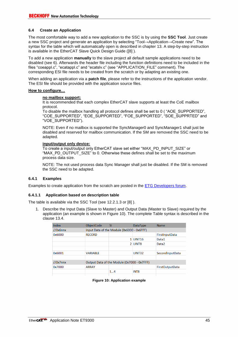
Application Note ET9300 45
6.4 Create an Application
The most comfortable way to add a new application to the SSC is by using the SSC Tool. Just create a new SSC project and generate an application by selecting “Tool→Application→Create new”. The syntax for the table which will automatically open is described in chapter 13. A step-by-step instruction is available in the EtherCAT Slave Quick Design Guide ([8] ).
To add a new application manually to the slave project all default sample applications need to be disabled (see 6). Afterwards the header file including the function definitions need to be included in the files “coeappl.c”, “ecatappl.c” and “ecatslv.c” (see “APPLICATION_FILE” comment). The corresponding ESI file needs to be created from the scratch or by adapting an existing one.
When adding an application via a patch file, please refer to the instructions of the application vendor. The ESI file should be provided with the application source files.
How to configure…
no mailbox support: It is recommended that each complex EtherCAT slave supports at least the CoE mailbox protocol. To disable the mailbox handling all protocol defines shall be set to 0 ( “AOE_SUPPORTED”, “COE_SUPPORTED”, “EOE_SUPPORTED”, “FOE_SUPPORTED”, “SOE_SUPPRTED” and “VOE_SUPPORTED”).
NOTE: Even if no mailbox is supported the SyncManager0 and SyncManager1 shall just be disabled and reserved for mailbox communication. If the SM are removed the SSC need to be adapted.
input/output only device: To create a input/output only EtherCAT slave set either “MAX_PD_INPUT_SIZE” or “MAX_PD_OUTPUT_SIZE” to 0. Otherwise these defines shall be set to the maximum process data size.
NOTE: The not used process data Sync Manager shall just be disabled. If the SM is removed the SSC need to be adapted.
6.4.1 Examples
Examples to create application from the scratch are posted in the ETG Developers forum.
6.4.1.1 Application based on description table
The table is available via the SSC Tool (see 12.2.1.3 or [8] ).
1. Describe the Input Data (Slave to Master) and Output Data (Master to Slave) required by the application (an example is shown in Figure 10). The complete Table syntax is described in the clause 13.4.
Figure 10: Application example
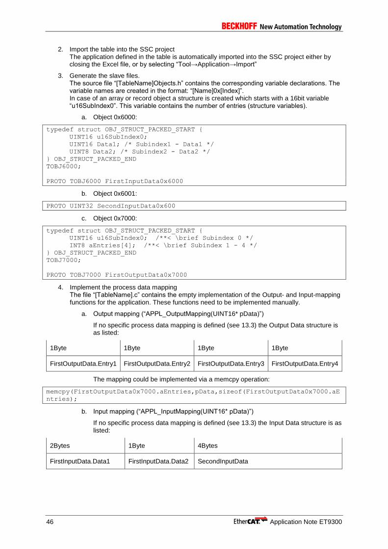
46 Application Note ET9300
2. Import the table into the SSC project The application defined in the table is automatically imported into the SSC project either by closing the Excel file, or by selecting “Tool→Application→Import”
3. Generate the slave files. The source file “[TableName]Objects.h” contains the corresponding variable declarations. The variable names are created in the format: “[Name]0x[Index]”. In case of an array or record object a structure is created which starts with a 16bit variable “u16SubIndex0”. This variable contains the number of entries (structure variables).
a. Object 0x6000:
typedef struct OBJ_STRUCT_PACKED_START {
UINT16 u16SubIndex0;
UINT16 Data1; /* Subindex1 - Data1 */
UINT8 Data2; /* Subindex2 - Data2 */
} OBJ_STRUCT_PACKED_END
TOBJ6000;
PROTO TOBJ6000 FirstInputData0x6000
b. Object 0x6001:
PROTO UINT32 SecondInputData0x600
c. Object 0x7000:
typedef struct OBJ_STRUCT_PACKED_START {
UINT16 u16SubIndex0; /**< \brief Subindex 0 */
INT8 aEntries[4]; /**< \brief Subindex 1 - 4 */
} OBJ_STRUCT_PACKED_END
TOBJ7000;
PROTO TOBJ7000 FirstOutputData0x7000
4. Implement the process data mapping The file “[TableName].c” contains the empty implementation of the Output- and Input-mapping functions for the application. These functions need to be implemented manually.
a. Output mapping (“APPL_OutputMapping(UINT16* pData)”)
If no specific process data mapping is defined (see 13.3) the Output Data structure is as listed:
1Byte 1Byte 1Byte 1Byte
FirstOutputData.Entry1 FirstOutputData.Entry2 FirstOutputData.Entry3 FirstOutputData.Entry4
The mapping could be implemented via a memcpy operation:
memcpy(FirstOutputData0x7000.aEntries,pData,sizeof(FirstOutputData0x7000.aE
ntries);
b. Input mapping (“APPL_InputMapping(UINT16* pData)”)
If no specific process data mapping is defined (see 13.3) the Input Data structure is as listed:
2Bytes 1Byte 4Bytes
FirstInputData.Data1 FirstInputData.Data2 SecondInputData
Application Note ET9300 47
The mapping could be implemented via the following code:
UINT8 *pu8Data = (UINT8 *) pData;
memcpy(&FirstInputData.Data1,pu8Data,(sizeof(FirstInputData)-2)); /* -2 is
required because the variable “SubIndex0” is not part of the process data
*/
pu8Data+=(sizeof(FirstInputData)-2);
memcpy(&SecondInputData,pu8Data,sizeof(SecondInputData));
5. Implement the application The file “[TableName].c” contains the empty implementation of the “APPL_Application()” function. In this function the logic and slave application physical signal handling shall be implemented.
6. Implement application-specific state transition handler functions The file “[TableName].c” contains the empty implementation of the application-specific state machine Application Interface functions (see chapter 17). In case the slave application requires to perform specific tasks during state transitions, these functions shall be implemented manually.
6.4.1.2 Sample Application process data enhancement
This example describes how to add new process data to the default sample application (SAMPLE_APPLICATION).
The default sample application provides the following process data:
- 32Bit Input Counter (0x6000)
- 32Bit Output Counter (0x7010)
If the Output Counter is 0 the Input Counter is incremented with every application cycle by 1, otherwise the Input Counter is the Output Counter +1.
Process data of the new application:
- 32Bit Input Counter (0x6000)
- 32Bit Result (0x6010)
- Output Values (0x7010)
SI1: Value1 (32Bit)
SI2: Value2 (32Bit)
0x6010 is the sum of 0x7010.1 and 0x7010.2. 0x6000 is incremented with every application cycle.
Initial Steps:
The initial steps describe how to create the basic sample application for the Beckhoff EL9800 EtherCAT evaluation board. Proceed with the “Adaption steps” if the basic sample application already exists (even if it was created for another platform).
1. Follow the steps 1-7 in chapter 3.1SSC Tool.
2. Select the custom configuration “EL9800 | 8Bit Digital I/O, 16Bit Analog Input”
3. Select group “Application”
a. Set “EL9800_APPLICATION” to 0
b. Set “SAMPLE_APPLICATION” to 1
4. Save the project and create new slave files (Project -> “Create new Slave Files”)
5. Program the slave EEPROM based on the created ESI file (see “APPLICATION NOTE EL9800” for further details)
6. Create an MPLAB project with the create source files (see “APPLICATION NOTE EL9800” for further details)
Adaption steps:

48 Application Note ET9300
1. File: sampleappl.h Create the entry description, the object name and the variable for the “32Bit Result” process data.
/**************************************************************************
* Object 0x6010: result object
**************************************************************************/
#ifdef _OBJD_
/* Entry description */
OBJCONST TSDOINFOENTRYDESC OBJMEM EntryDesc0x6010 = {DEFTYPE_UNSIGNED32,
0x10, ACCESS_READ | OBJACCESS_TXPDOMAPPING};
/* Object name */
OBJCONST UCHAR OBJMEM aName0x6010[] = "Result";
#endif //#ifdef _OBJD_
/* Variable to handle the object data */
PROTO UINT32 ResultObj6010;
2. File: sampleappl.h Change the existing definition of object 0x7010 (32Bit Output Counter) to a record object which handles more than one process data (the new object shall include two variables (entries)). The variable for the entry description is changed to an array and the description for SubIndex0 and for the second variable is added. The name variable is enhanced by the names for the entries (each “subname” is terminated by “\000” and the whole string is terminated by “\377”). For the object data itself a structure including a variable for the subindex0 and the two process data variables is defined. See chapter 11 for detailed information regarding the definitions.
/**************************************************************************
* Object 0x7010: output values object
**************************************************************************/
#ifdef _OBJD_
OBJCONST TSDOINFOENTRYDESC OBJMEM asEntryDesc0x7010[] = {
/* Entry description of Subindex0 */
{DEFTYPE_UNSIGNED8, 0x08, ACCESS_READ},
/* Entry description of the first entry “Value1” */
{DEFTYPE_UNSIGNED32, 0x20, ACCESS_READ | OBJACCESS_RXPDOMAPPING},
/* Entry description of the second entry “Value2” */
{DEFTYPE_UNSIGNED32, 0x20, ACCESS_READ | OBJACCESS_RXPDOMAPPING}};
/* Name of the object and the entries */
OBJCONST UCHAR OBJMEM aName0x7010[] = "Output
values\000Value1\000Value2\000\377";
#endif //#ifdef _OBJD_
/* Structure to handle the object data*/
typedef struct OBJ_STRUCT_PACKED_START {
UINT16 u16SubIndex0;
UINT32 Value1;
UINT32 Value2;
} OBJ_STRUCT_PACKED_END
TOBJ7010;
PROTO TOBJ7010 OutputData
#ifdef _SAMPLE_APPLICATION_
= {0x02, 0x00, 0x00}
#endif
;
3. File: sampleappl.h Add information about the new process data to the PDO mapping objects. The changed code is marked bold red. NOTE: This step is required to have consistent process data information.
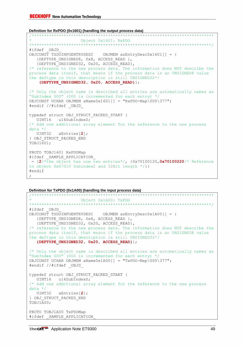
Application Note ET9300 49
Definition for RxPDO (0x1601) (handling the output process data)
/**************************************************************************
* Object 0x1601: RxPDO
**************************************************************************/
#ifdef _OBJD_
OBJCONST TSDOINFOENTRYDESC OBJMEM asEntryDesc0x1601[] = {
{DEFTYPE_UNSIGNED8, 0x8, ACCESS_READ },
{DEFTYPE_UNSIGNED32, 0x20, ACCESS_READ},
/* reference to the new process data. The information does NOT describe the
process data itself, that means if the process data is an UNSIGNED8 value
the deftype in this description is still UNSIGNED32*/
{DEFTYPE_UNSIGNED32, 0x20, ACCESS_READ}};
/* Only the object name is described all entries are automatically names as
“SubIndex 000” (000 is incremented for each entry) */
OBJCONST UCHAR OBJMEM aName0x1601[] = "RxPDO-Map\000\377";
#endif //#ifdef _OBJD_
typedef struct OBJ_STRUCT_PACKED_START {
UINT16 u16SubIndex0;
/* Add one additional array element for the reference to the new process
data */
UINT32 aEntries[2];
} OBJ_STRUCT_PACKED_END
TOBJ1601;
PROTO TOBJ1601 RxPDOMap
#ifdef _SAMPLE_APPLICATION_
= {2/*the object has now two entries*/, {0x70100120,0x70100220/* Reference
to object 0x07010 Subindex2 and 32Bit length */}}
#endif
;
Definition for TxPDO (0x1A00) (handling the input process data)
/**************************************************************************
* Object 0x1A00: TxPDO
**************************************************************************/
#ifdef _OBJD_
OBJCONST TSDOINFOENTRYDESC OBJMEM asEntryDesc0x1A00[] = {
{DEFTYPE_UNSIGNED8, 0x8, ACCESS_READ },
{DEFTYPE_UNSIGNED32, 0x20, ACCESS_READ},
/* reference to the new process data. The information does NOT describe the
process data itself, that means if the process data is an UNSIGNED8 value
the deftype in this description is still UNSIGNED32*/
{DEFTYPE_UNSIGNED32, 0x20, ACCESS_READ}};
/* Only the object name is described all entries are automatically names as
“SubIndex 000” (000 is incremented for each entry) */
OBJCONST UCHAR OBJMEM aName0x1A00[] = "TxPDO-Map\000\377";
#endif //#ifdef _OBJD_
typedef struct OBJ_STRUCT_PACKED_START {
UINT16 u16SubIndex0;
/* Add one additional array element for the reference to the new process
data */
UINT32 aEntries[2];
} OBJ_STRUCT_PACKED_END
TOBJ1A00;
PROTO TOBJ1A00 TxPDOMap
#ifdef _SAMPLE_APPLICATION_

50 Application Note ET9300
= {2/*the object has now two entries*/, {0x60000020,0x60100020/* Reference
to object 0x06010 Subindex0 and 32Bit length */}}
#endif
;
4. File: sampleappl.h Add/Update the references in the object dictionary
TOBJECT OBJMEM ApplicationObjDic[] = {
/* Object 0x1601 */
{NULL,NULL, 0x1601, {DEFTYPE_PDOMAPPING, 2 | (OBJCODE_REC << 8)},
asEntryDesc0x1601, aName0x1601, &RxPDOMap, NULL, NULL, 0x0000 },
/* Object 0x1A00 */
{NULL,NULL, 0x1A00, {DEFTYPE_PDOMAPPING, 2 | (OBJCODE_REC << 8)},
asEntryDesc0x1A00, aName0x1A00, &TxPDOMap, NULL, NULL, 0x0000 },
…
/* Object 0x6010 */
{NULL,NULL, 0x6010, {DEFTYPE_UNSIGNED32, 0 | (OBJCODE_VAR << 8)},
&EntryDesc0x6010, aName0x6010, &ResultObj6010, NULL, NULL, 0x0000 },
/* Object 0x7010 */
{NULL,NULL, 0x7010, {DEFTYPE_RECORD, 2 | (OBJCODE_REC << 8)},
asEntryDesc0x7010, aName0x7010, &OutputData, NULL, NULL, 0x0000 },
{NULL,NULL, 0xFFFF, {0, 0}, NULL, NULL, NULL, NULL}};
5. File: sampleappl.c Update the expected process data size (which is similar to the size of the corresponding SyncManager). NOTE: if one of the values mismatch with the information in the ESI file the slave will abort the state transition from PreOP to SafeOP with the Error code 0x1E or 0x1D (depending on the wrong value)
UINT16 APPL_GenerateMapping(UINT16 *pInputSize,UINT16 *pOutputSize)
{
/* 32Bit cyclic counter (0x6000) and 32Bit Result (*0x6010)/
*pInputSize = 8;
/*32Bit Value1 (0x7010.1) and 32Bit Value2 (0x7010.2)*/
*pOutputSize = 8;
return ALSTATUSCODE_NOERROR;
}
6. File: sampleappl.c Update the input process data mapping function to copy also the new process data.
void APPL_InputMapping(UINT16* pData)
{
MEMCPY(pData,&InputCounter,SIZEOF(InputCounter));
/* Increment the data pointer to write the next process data (pData refers
to the buffer which is copied to the ESC memory controlled by SyncManager 3
(input process data) */
pData +=2;
/* Copy the value the result */
MEMCPY(pData,&ResultObj6010,SIZEOF(ResultObj6010));
}
7. File: sampleappl.c Update the output process data mapping function to update the variables handling the output process data.
void APPL_OutputMapping(UINT16* pData)

Application Note ET9300 51
{
/* Update the variable “Value1” */
MEMCPY(&OutputData.Value1,pData,SIZEOF(OutputData.Value1));
/* Increment the data pointer to write the next process data (pData refers
to the buffer which is copied to the ESC memory controlled by SyncManager 3
(input process data) */
pData += 2;
/* Update the variable “Value2” */
MEMCPY(&OutputData.Value2,pData,SIZEOF(OutputData.Value2));
}
8. File: sampleappl.c Update the Application.
void APPL_Application(void)
{
/*Hardware independent sample application*/
ResultObj6010 = OutputData.Value1 + OutputData.Value2;
InputCounter++;
}
9. File: ESI file (in xml format) Update the entries of the RxPdo and TxPdo elements according to step 3.
<RxPdo Mandatory="true" Fixed="true" Sm="2">
<Index>#x1601</Index>
<Name>RxPDO</Name>
<Entry>
<Index>#x7010</Index>
<SubIndex>1</SubIndex>
<BitLen>32</BitLen>
<Name>Value1</Name>
<DataType>UDINT</DataType>
</Entry>
<Entry>
<Index>#x7010</Index>
<SubIndex>2</SubIndex>
<BitLen>32</BitLen>
<Name>Value2</Name>
<DataType>UDINT</DataType>
</Entry>
</RxPdo>
<TxPdo Mandatory="true" Fixed="true" Sm="3">
<Index>#x1a00</Index>
<Name>TXPDO</Name>
<Entry>
<Index>#x6000</Index>
<SubIndex>0</SubIndex>
<BitLen>32</BitLen>
<Name>32Bit Input</Name>
<DataType>UDINT</DataType>
</Entry>
<Entry>
<Index>#x6010</Index>
<SubIndex>0</SubIndex>
<BitLen>32</BitLen>
<Name>Result</Name>
<DataType>UDINT</DataType>
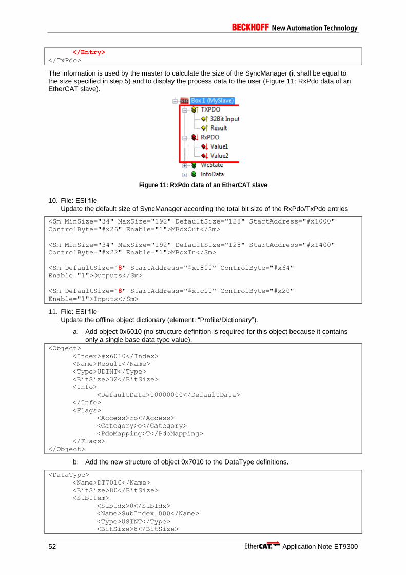
52 Application Note ET9300
</Entry>
</TxPdo>
The information is used by the master to calculate the size of the SyncManager (it shall be equal to the size specified in step 5) and to display the process data to the user (Figure 11: RxPdo data of an EtherCAT slave).
Figure 11: RxPdo data of an EtherCAT slave
10. File: ESI file Update the default size of SyncManager according the total bit size of the RxPdo/TxPdo entries
<Sm MinSize="34" MaxSize="192" DefaultSize="128" StartAddress="#x1000"
ControlByte="#x26" Enable="1">MBoxOut</Sm>
<Sm MinSize="34" MaxSize="192" DefaultSize="128" StartAddress="#x1400"
ControlByte="#x22" Enable="1">MBoxIn</Sm>
<Sm DefaultSize="8" StartAddress="#x1800" ControlByte="#x64"
Enable="1">Outputs</Sm>
<Sm DefaultSize="8" StartAddress="#x1c00" ControlByte="#x20"
Enable="1">Inputs</Sm>
11. File: ESI file Update the offline object dictionary (element: “Profile/Dictionary”).
a. Add object 0x6010 (no structure definition is required for this object because it contains only a single base data type value).
<Object>
<Index>#x6010</Index>
<Name>Result</Name>
<Type>UDINT</Type>
<BitSize>32</BitSize>
<Info>
<DefaultData>00000000</DefaultData>
</Info>
<Flags>
<Access>ro</Access>
<Category>o</Category>
<PdoMapping>T</PdoMapping>
</Flags>
</Object>
b. Add the new structure of object 0x7010 to the DataType definitions.
<DataType>
<Name>DT7010</Name>
<BitSize>80</BitSize>
<SubItem>
<SubIdx>0</SubIdx>
<Name>SubIndex 000</Name>
<Type>USINT</Type>
<BitSize>8</BitSize>
Application Note ET9300 53
<BitOffs>0</BitOffs>
<Flags>
<Access>ro</Access>
<Category>o</Category>
</Flags>
</SubItem>
<SubItem>
<SubIdx>1</SubIdx>
<Name>Value1</Name>
<Type>UDINT</Type>
<BitSize>32</BitSize>
<BitOffs>16</BitOffs>
<Flags>
<Access>ro</Access>
<Category>o</Category>
</Flags>
</SubItem>
<SubItem>
<SubIdx>2</SubIdx>
<Name>Value2</Name>
<Type>UDINT</Type>
<BitSize>32</BitSize>
<BitOffs>48</BitOffs>
<Flags>
<Access>ro</Access>
<Category>o</Category>
</Flags>
</SubItem>
</DataType>
c. Update the object 0x7010.
<Object>
<Index>#x7010</Index>
<Name>OutputCounter</Name>
<Type>DT7010</Type>
<BitSize>80</BitSize>
<Info>
<SubItem>
<Name>SubIndex 000</Name>
<Info>
<DefaultData>02</DefaultData>
</Info>
</SubItem>
<SubItem>
<Name>Value1</Name>
<Info>
<DefaultData>00000000</DefaultData>
</Info>
</SubItem>
<SubItem>
<Name>Value2</Name>
<Info>
<DefaultData>00000000</DefaultData>
</Info>
</SubItem>
</Info>
<Flags>
<Access>rw</Access>
<Category>o</Category>
<PdoMapping>R</PdoMapping>
</Flags>
</Object>
54 Application Note ET9300
d. Update the PDO mapping object structure. NOTE: the definition “DT1601” can be used for object 0x1601 and object 0x1A00 because the object structures are equal.
<DataType>
<Name>DT1601</Name>
<BitSize>80</BitSize>
<SubItem>
<SubIdx>0</SubIdx>
<Name>SubIndex 000</Name>
<Type>USINT</Type>
<BitSize>8</BitSize>
<BitOffs>0</BitOffs>
<Flags>
<Access>ro</Access>
<Category>o</Category>
</Flags>
</SubItem>
<SubItem>
<SubIdx>1</SubIdx>
<Name>SubIndex 001</Name>
<Type>UDINT</Type>
<BitSize>32</BitSize>
<BitOffs>16</BitOffs>
<Flags>
<Access>ro</Access>
<Category>o</Category>
</Flags>
</SubItem>
<SubItem>
<SubIdx>2</SubIdx>
<Name>SubIndex 002</Name>
<Type>UDINT</Type>
<BitSize>32</BitSize>
<BitOffs>48</BitOffs>
<Flags>
<Access>ro</Access>
<Category>o</Category>
</Flags>
</SubItem>
</DataType>
e. Update PDO mapping object.
<Object>
<Index>#x1601</Index>
<Name>RxPDO-Map</Name>
<Type>DT1601</Type>
<BitSize>80</BitSize>
<Info>
<SubItem>
<Name>SubIndex 000</Name>
<Info>
<DefaultData>02</DefaultData>
</Info>
</SubItem>
<SubItem>
<Name>SubIndex 001</Name>
<Info>
<DefaultData>20011070</DefaultData>
</Info>
</SubItem>
<SubItem>
<Name>SubIndex 002</Name>

Application Note ET9300 55
<Info>
<DefaultData>20021070</DefaultData>
</Info>
</SubItem>
</Info>
<Flags>
<Access>ro</Access>
<Category>o</Category>
</Flags>
</Object>
<Object>
<Index>#x1a00</Index>
<Name>TxPDO-Map</Name>
<Type>DT1601</Type>
<BitSize>80</BitSize>
<Info>
<SubItem>
<Name>SubIndex 000</Name>
<Info>
<DefaultData>02</DefaultData>
</Info>
</SubItem>
<SubItem>
<Name>SubIndex 001</Name>
<Info>
<DefaultData>20000060</DefaultData>
</Info>
</SubItem>
<SubItem>
<Name>SubIndex 002</Name>
<Info>
<DefaultData>20101060</DefaultData>
</Info>
</SubItem>
</Info>
<Flags>
<Access>ro</Access>
<Category>o</Category>
</Flags>
</Object>
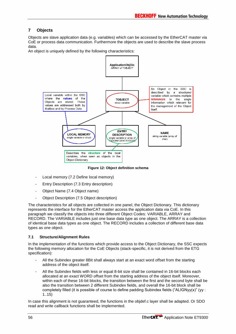
56 Application Note ET9300
7 Objects
Objects are slave application data (e.g. variables) which can be accessed by the EtherCAT master via CoE or process data communication. Furthermore the objects are used to describe the slave process data. An object is uniquely defined by the following characteristics:
Figure 12: Object definition schema
- Local memory (7.2 Define local memory)
- Entry Description (7.3 Entry description)
- Object Name (7.4 Object name)
- Object Description (7.5 Object description)
The characteristics for all objects are collected in one panel, the Object Dictionary. This dictionary represents the interface for the EtherCAT master access the application data via CoE. In this paragraph we classify the objects into three different Object Codes: VARIABLE, ARRAY and RECORD. The VARIABLE includes just one base data type as one object. The ARRAY is a collection of identical base data types as one object. The RECORD includes a collection of different base data types as one object.
7.1 Structure/Alignment Rules
In the implementation of the functions which provide access to the Object Dictionary, the SSC expects the following memory allocation for the CoE Objects (stack-specific, it is not derived from the ETG specification):
- All the Subindex greater 8Bit shall always start at an exact word offset from the starting address of the object itself.
- All the Subindex fields with less or equal 8-bit size shall be contained in 16-bit blocks each allocated at an exact WORD offset from the starting address of the object itself. Moreover, within each of these 16-bit blocks, the transition between the first and the second byte shall be also the transition between 2 different Subindex fields, and overall the 16-bit block shall be completely filled (it is possible of course to define padding Subindex fields (“ALIGNyy(x)” (yy : 1..15)
In case this alignment is not guaranteed, the functions in the objdef.c layer shall be adapted. Or SDO read and write callback functions shall be implemented.
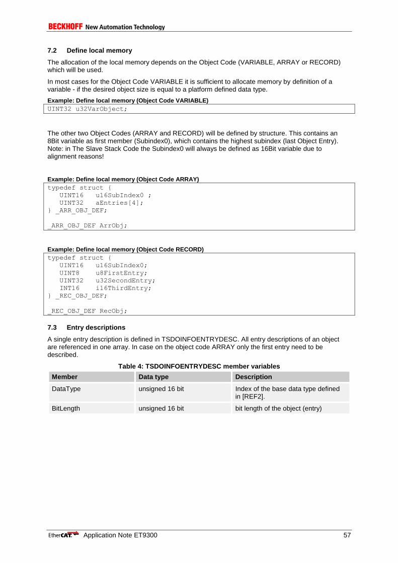
Application Note ET9300 57
7.2 Define local memory
The allocation of the local memory depends on the Object Code (VARIABLE, ARRAY or RECORD) which will be used.
In most cases for the Object Code VARIABLE it is sufficient to allocate memory by definition of a variable - if the desired object size is equal to a platform defined data type.
Example: Define local memory (Object Code VARIABLE)
UINT32 u32VarObject;
The other two Object Codes (ARRAY and RECORD) will be defined by structure. This contains an 8Bit variable as first member (Subindex0), which contains the highest subindex (last Object Entry). Note: in The Slave Stack Code the Subindex0 will always be defined as 16Bit variable due to alignment reasons!
Example: Define local memory (Object Code ARRAY)
typedef struct {
UINT16 u16SubIndex0 ;
UINT32 aEntries[4];
} _ARR_OBJ_DEF;
_ARR_OBJ_DEF ArrObj;
Example: Define local memory (Object Code RECORD)
typedef struct {
UINT16 u16SubIndex0;
UINT8 u8FirstEntry;
UINT32 u32SecondEntry;
INT16 i16ThirdEntry;
} _REC_OBJ_DEF;
_REC_OBJ_DEF RecObj;
7.3 Entry descriptions
A single entry description is defined in TSDOINFOENTRYDESC. All entry descriptions of an object are referenced in one array. In case on the object code ARRAY only the first entry need to be described.
Table 4: TSDOINFOENTRYDESC member variables
Member Data type Description
DataType unsigned 16 bit Index of the base data type defined in [REF2].
BitLength unsigned 16 bit bit length of the object (entry)
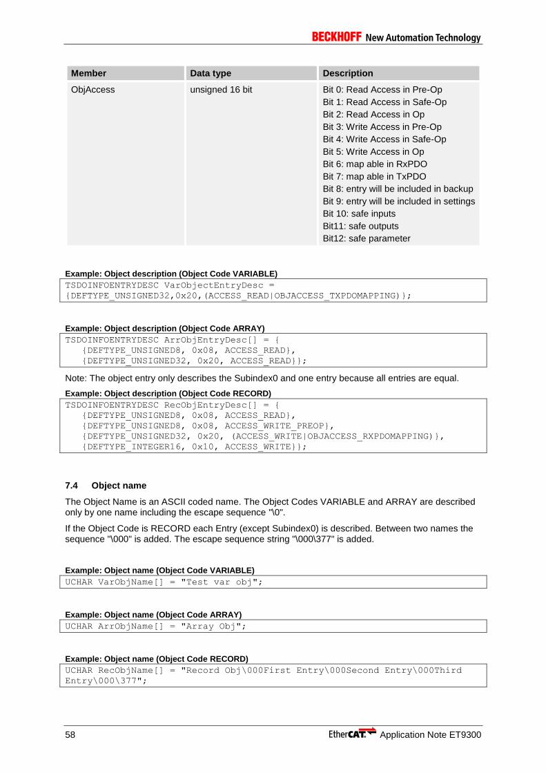
58 Application Note ET9300
Member Data type Description
ObjAccess unsigned 16 bit Bit 0: Read Access in Pre-Op
Bit 1: Read Access in Safe-Op
Bit 2: Read Access in Op
Bit 3: Write Access in Pre-Op
Bit 4: Write Access in Safe-Op
Bit 5: Write Access in Op
Bit 6: map able in RxPDO
Bit 7: map able in TxPDO
Bit 8: entry will be included in backup
Bit 9: entry will be included in settings
Bit 10: safe inputs
Bit11: safe outputs
Bit12: safe parameter
Example: Object description (Object Code VARIABLE)
TSDOINFOENTRYDESC VarObjectEntryDesc =
{DEFTYPE_UNSIGNED32,0x20,(ACCESS_READ|OBJACCESS_TXPDOMAPPING)};
Example: Object description (Object Code ARRAY)
TSDOINFOENTRYDESC ArrObjEntryDesc[] = {
{DEFTYPE_UNSIGNED8, 0x08, ACCESS_READ},
{DEFTYPE_UNSIGNED32, 0x20, ACCESS_READ}};
Note: The object entry only describes the Subindex0 and one entry because all entries are equal.
Example: Object description (Object Code RECORD)
TSDOINFOENTRYDESC RecObjEntryDesc[] = {
{DEFTYPE_UNSIGNED8, 0x08, ACCESS_READ},
{DEFTYPE_UNSIGNED8, 0x08, ACCESS_WRITE_PREOP},
{DEFTYPE_UNSIGNED32, 0x20, (ACCESS_WRITE|OBJACCESS_RXPDOMAPPING)},
{DEFTYPE_INTEGER16, 0x10, ACCESS_WRITE}};
7.4 Object name
The Object Name is an ASCII coded name. The Object Codes VARIABLE and ARRAY are described only by one name including the escape sequence "\0".
If the Object Code is RECORD each Entry (except Subindex0) is described. Between two names the sequence "\000" is added. The escape sequence string "\000\377" is added.
Example: Object name (Object Code VARIABLE)
UCHAR VarObjName[] = "Test var obj";
Example: Object name (Object Code ARRAY)
UCHAR ArrObjName[] = "Array Obj";
Example: Object name (Object Code RECORD)
UCHAR RecObjName[] = "Record Obj\000First Entry\000Second Entry\000Third
Entry\000\377";
Application Note ET9300 59
7.5 Object description
The object description connects all object characteristics in one type “TOBJECT” (structure “OBJECT”). The member variables of OBJECT are listed in Table 5.
Table 5: "TOBJECT" member variables
Member Data type Description
Prev Entry struct OBJECT Pointer to previous dictionary entry.
Only available if the object dictionary entries are dynamic linked (STATIC_OBJECT_DIC = 0).
Next Entry struct OBJECT Pointer to next dictionary entry.
Only available if the object dictionary entries are dynamic linked (STATIC_OBJECT_DIC = 0).
Index unsigned 16 bit Object index of the described object. The object value depends on the type of EtherCAT slave and object usage (7.6Index Ranges)
ObjDesc TSDOINFOOBJDESC (32 bit)
Data Type unsigned 16 bit Includes the data type index of the object. (defined in [2] )
ObjFlags unsigned 16 bit Bit 0-7: Max Subindex (value of subindex 0)
Bit 8-15: Object Code (defined in [2] )
pEntryDesc TSDOINFOENTRYDESC * Pointer to object description. Defined in “7.3Entry description”
pName unsigned char * Pointer to object name. Defined in “7.4Object name”
pVarPtr void * Pointer to local memory. Defined in “7.2Define local memory”
Read Pointer to Read Function. The prototype is listed below. This function will be called when an SDO upload is received. If this pointer is NULL the standard SDO upload function is executed.
Prototype:
UINT8 ReadFunction (
UINT16 Index,
UINT8 Subindex,
UINT32 Size,
UINT16 MBXMEM * pData,
UINT8 bCompleteAccess )

60 Application Note ET9300
Member Data type Description
Write Pointer to Write Function. The prototype is listed below. This function will be called when an SDO download is received. If this pointer is NULL the standard SDO download function is executed.
Prototype:
UINT8 WriteFunction(
UINT16 index,
UINT8 subindex,
UINT32 dataSize,
UINT16 MBXMEM * pData,
UINT8 bCompleteAccess )
NonVolatileOffset unsigned 16 bit determine offset within nonvolatile memory. This value is evaluated if the object should be stored(load) as backup parameter.
Example: Object dictionary entry description (Object Code VARIABLE)
TOBJECT VarObj_ODEntryDesc = {0x6000, {DEFTYPE_UNSIGNED32, 0 | (OBJCODE_VAR
<< 8)}, &VarObjectEntryDesc, VarObjName, &u32VarObject, NULL, NULL, 0x0000
};
Example: Object dictionary entry description (Object Code ARRAY)
TOBJECT ArrObj_ODEntryDesc = {0x9000, {DEFTYPE_UNSIGNED32, 5 | (OBJCODE_ARR
<< 8)}, ArrObjEntryDesc, ArrObjName, &ArrObj, NULL, NULL, 0x0000 };
Example: Object dictionary entry description (Object Code RECORD)
TOBJECT RecObj_ODEntryDesc = {0x7000, {DEFTYPE_RECORD, 4 | (OBJCODE_REC <<
8)}, RecObjEntryDesc, RecObjName, &RecObj, NULL, NULL, 0x0000 };
7.6 Index Ranges
The index ranges depends on the used EtherCAT profile. See Ref.[5] for further information. The Basic index ranges used in the SSC are listed in Table 6: Basic object index ranges.
Table 6: Basic object index ranges
Index Range Description
0x0000 – 0x0FFF Data Type Area
0x1000 – 0x1FFF Communication Area
0x1600 – 0x19FF RxPDO Mapping
0x1A00 – 0x1BFF TxPDO Mapping
0x1C10 – 0x1C2F Sync Manager PDO Assignment
0x1C30 – 0x1C4F Sync Manager Parameters
0x2000 – 0x5FFF Manufacturer specific Area
0x6000 – 0x6FFF Input Area
0x7000 – 0x7FFF Output Area
0x8000 – 0x8FFF Configuration Area
0x9000 – 0x9FFF Information Area
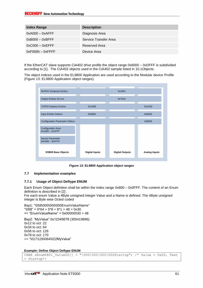
Application Note ET9300 61
Index Range Description
0xA000 – 0xAFFF Diagnosis Area
0xB000 – 0xBFFF Service Transfer Area
0xC000 – 0xEFFF Reserved Area
0xF000h – 0xFFFF Device Area
If the EtherCAT slave supports CiA402 drive profile the object range 0x6000 – 0xDFFF is subdivided according to [1] . The CiA402 objects used in the CiA402 sample listed in 10.1Objects.
The object indices used in the EL9800 Application are used according to the Modular device Profile (Figure 13: EL9800 Application object ranges).
RxPDO (Outputs) 0x16xx 0x1601
Output Entries 0x7xxx 0x7010
TxPDO (Inputs) 0x1Axx 0x1A00 0x1A02
Input Entries 0x6xxx 0x6000 0x6020
Configuration Parameter 0x8xxx 0x8020
Configuration Area
0x1000 – 0x1FFF
Device Parameter
0xF000 – 0xFFFF
El9800 Base Objects Digital Inputs Digital Outputs Analog Inputs
Figure 13: EL9800 Application object ranges
7.7 Implementation examples
7.7.1 Usage of Object Deftype ENUM
Each Enum Object definition shall be within the index range 0x800 – 0x0FFF. The content of an Enum definition is described in [2] . For each enum Value a 4Byte unsigned integer Value and a Name is defined. The 4Byte unsigned integer is Byte wise Octed coded
Bsp1: "\058\000\000\000EnumValueName" “\058” = 0*64 + 5*8 + 8*1 = 48 = 0x30 => “EnumValueName” = 0x00000030 = 48
Bsp2: “MyValue” 0x12345678 (305419896) 0x12 to oct: 22 0x34 to oct: 64 0x56 to oct: 126 0x78 to oct: 170 => “\017\126\064\022MyValue”
Example: Define Object Deftype ENUM
CHAR sEnum0801_Value00[] = "\000\000\000\000Startup"; /* Value = 0x00, Text
= Startup*/
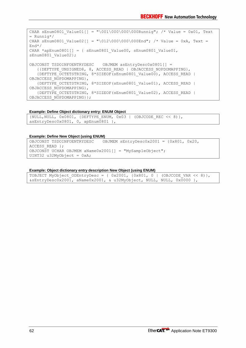
62 Application Note ET9300
CHAR sEnum0801_Value01[] = "\001\000\000\000Runnig"; /* Value = 0x01, Text
= Runnig*/
CHAR sEnum0801_Value02[] = "\012\000\000\000End"; /* Value = 0xA, Text =
End*/
CHAR *apEnum0801[] = { sEnum0801_Value00, sEnum0801_Value01,
sEnum0801_Value02};
OBJCONST TSDOINFOENTRYDESC OBJMEM asEntryDesc0x0801[] =
{{DEFTYPE_UNSIGNED8, 8, ACCESS_READ | OBJACCESS_NOPDOMAPPING},
{DEFTYPE_OCTETSTRING, 8*SIZEOF(sEnum0801_Value00), ACCESS_READ |
OBJACCESS_NOPDOMAPPING},
{DEFTYPE_OCTETSTRING, 8*SIZEOF(sEnum0801_Value01), ACCESS_READ |
OBJACCESS_NOPDOMAPPING},
{DEFTYPE_OCTETSTRING, 8*SIZEOF(sEnum0801_Value02), ACCESS_READ |
OBJACCESS_NOPDOMAPPING}};
Example: Define Object dictionary entry: ENUM Object
{NULL,NULL, 0x0801, {DEFTYPE_ENUM, 0x03 | (OBJCODE_REC << 8)},
asEntryDesc0x0801, 0, apEnum0801 },
Example: Define New Object (using ENUM)
OBJCONST TSDOINFOENTRYDESC OBJMEM sEntryDesc0x2001 = {0x801, 0x20,
ACCESS_READ };
OBJCONST UCHAR OBJMEM aName0x2001[] = "MySampleObject";
UINT32 u32MyObject = 0xA;
Example: Object dictionary entry description New Object (using ENUM)
TOBJECT MyObject_ODEntryDesc = { 0x2001, {0x801, 0 | (OBJCODE_VAR << 8)},
&sEntryDesc0x2001, aName0x2001, & u32MyObject, NULL, NULL, 0x0000 },

Application Note ET9300 63
8 Mailbox
8.1 CoE (CAN application protocol over EtherCAT)
8.1.1 Backup Parameter support
The SSC supports the handling of backup parameters. Backup parameters are object entries which are can be stored in non-volatile memory. To enable that feature set the define “BACKUP_PARAMETER_SUPPORTED” to 1.
The following entries are used to control the backup behavior.
- 0x1010.1 Store backup value (if 0x65766173 is written the backup parameters are stored, see Figure 16).
- 0x1011.1 Restore default values (if 0x64616F6C is written the default backup parameters are read, see Figure 15).
- 0x10F0.1 Checksum (readonly, contains the current checksum of the stored backup parameter data)
On power up of the slave the following functions are called (Figure 14).

64 Application Note ET9300
COE_ObjInit()
EE_IsDefaultDataInitialized()
EE_ResetFlashData()
No
InitDefaultEntries()
EE_WriteWordsToNonVolatileMemory()
EE_StoreDefaultData()
Loop over all Backup Entries
LoadBackupEntries()
EE_ReadWordsFromNonVolatileMemory()Loop over all
Backup Entries
Figure 14: Backup parameter Initialization
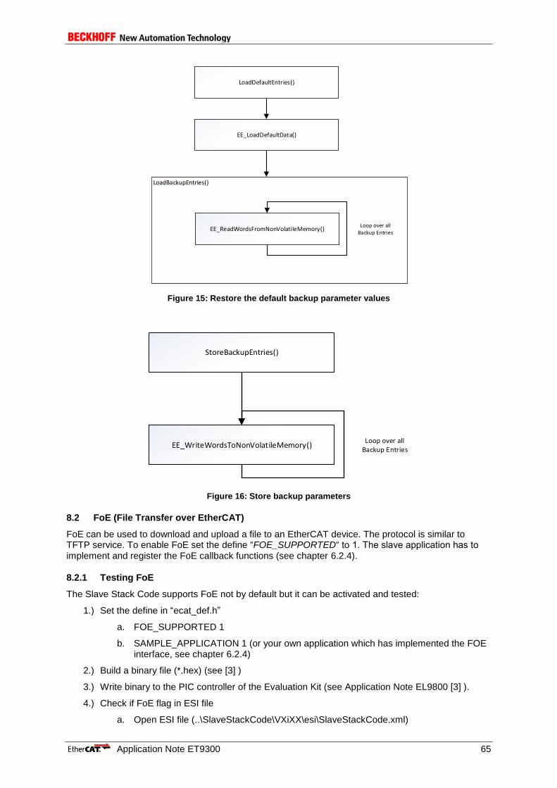
Application Note ET9300 65
LoadDefaultEntries()
EE_LoadDefaultData()
LoadBackupEntries()
EE_ReadWordsFromNonVolatileMemory()Loop over all
Backup Entries
Figure 15: Restore the default backup parameter values
StoreBackupEntries()
EE_WriteWordsToNonVolatileMemory()Loop over all
Backup Entries
Figure 16: Store backup parameters
8.2 FoE (File Transfer over EtherCAT)
FoE can be used to download and upload a file to an EtherCAT device. The protocol is similar to TFTP service. To enable FoE set the define “FOE_SUPPORTED“ to 1. The slave application has to implement and register the FoE callback functions (see chapter 6.2.4).
8.2.1 Testing FoE
The Slave Stack Code supports FoE not by default but it can be activated and tested:
1.) Set the define in “ecat_def.h”
a. FOE_SUPPORTED 1
b. SAMPLE_APPLICATION 1 (or your own application which has implemented the FOE interface, see chapter 6.2.4)
2.) Build a binary file (*.hex) (see [3] )
3.) Write binary to the PIC controller of the Evaluation Kit (see Application Note EL9800 [3] ).
4.) Check if FoE flag in ESI file
a. Open ESI file (..\SlaveStackCode\VXiXX\esi\SlaveStackCode.xml)
66 Application Note ET9300
b. Check if the element EtherCATInfo : Descriptions : Devices : Device : Mailbox : FoE is available. It has only to be present. No content is necessary.
5.) If the ESI file was edited replace the original ESI file from TwinCAT (../Io/Ethercat/SlaveStackCode.xml) with the edited one.
6.) Rewrite SII if ESI file was edited (see[3] )
7.) Restart device and restart TwinCAT
8.) Scan Network
9.) Select device (Evaluation Kit with FoE activated)
10.) Select Tab-“Online” and read or write a file to the slave device be pressing the corresponding buttons in the File Access over EtherCAT – group box.
8.3 EoE (Ethernet over EtherCAT)
EoE is used to send Ethernet telegrams to EtherCAT devices (supporting a Ethernet stack). EoE is used for Ethernet communication i.e. a device supports a web server that can be accessed via browser.
8.3.1 Implementation
The EoE stack is Implemented in the files ecateoe.* (basic EoE handling) and eoeappl.* (EoE application handling).To support EoE the switch “EOE_SUPPORTED” need to be set to 1 and the EoE flag need to be set in the ESI (REF.[4] ). Depending on the switch “STATIC_ETHERNET_BUFFER” dynamic memory is allocated for Ethernet frame handling or a fixed memory is used (1514 Bytes). By default the stack only handles ICMP and ARP frames.
8.3.1.1 Sending EoE datagrams
To send EoE datagram from the EtherCAT slave to the EtherCAT master the function “EOE_SendFrameReq()” shall be called.

Application Note ET9300 67
EOE_SendFrameReq()
SendFragment()
MBX_MailboxSendReq()
Pending frame?
Yes
Full Mbx buffer?
Yes
Frame complete?
No
Store datagram in
„pEoESendStored“
No
No
Clear
„bSendFramePending“ flag
This function is called to send an
ethernet frame.
(Slave -> Master)
If no ethernet frame is currently
pending
(„bSendFramePending“ is FALSE).
Split the ethernet frame into EoE
datagrams
Generic send mailbox handling
(write mailbox data to Input Mbx
SyncManger (default: SM1))
If MBX_MailboxSendReq() returns
a value unequal 0 the mailbox
buffer is full
If the complete ethernet frame was
splitted into EoE datagrams and at
least enqued for sending
The function
„EOE_SendFrameReq()“
need to be called once
again by the application
If frame was not complete
sended the flag
„bSendFramePending“ is
still set and
„SendFragment()“ is
called by
„EOE_ContinueInd()“Yes
Figure 17: Send EoE datagram
8.3.1.2 Receiving EoE datagrams
Received EoE datagrams are handled by the function “EOE_ServiceInd()” which is called from the generic mailbox stack. The program flow is shown in Figure 18.
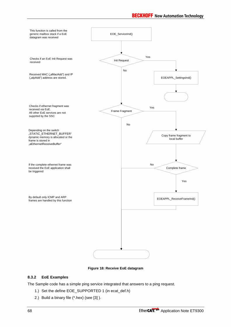
68 Application Note ET9300
EOE_ServiceInd()
Init Request
Yes
Yes
No
No
Copy frame fragment to
local buffer
This function is called from the
generic mailbox stack if a EoE
datagram was received
Checks if an EoE Init Request was
received
EOEAPPL_SettingsInd()
Frame Fragment
EOEAPPL_ReceiveFrameInd()
Checks if ethernet fragment was
received via EoE.
All other EoE services are not
supprted by the SSC
Received MAC („aMacAdd“) and IP
(„aIpAdd“) address are stored.
Complete frame
Depending on the switch
„STATIC_ETHERNET_BUFFER“
dynamic memory is allocated or the
frame is stored in
„aEthernetReceiveBuffer“
If the complete ethernet frame was
received the EoE application shall
be triggered
No
Yes
By default only ICMP and ARP
frames are handled by this function
Figure 18: Receive EoE datagram
8.3.2 EoE Examples
The Sample code has a simple ping service integrated that answers to a ping request.
1.) Set the define EOE_SUPPORTED 1 (in ecat_def.h)
2.) Build a binary file (*.hex) (see [3] ).

Application Note ET9300 69
3.) Write binary to the PIC controller of the Evaluation Kit (see Application Note EL9800 [3] ).
4.) Change EoE flag in ESI file
a. Open ESI file (..\SlaveStackCode\VXiXX\esi\SlaveStackCode.xml)
b. Open corresponding entry
i. Board 4a (new board): EL9800-SPI-PIC24
ii. Board 2 (former board): EL9800-SPI-PIC18
iii. If CiA 402 example is used: EL9800-CiA402
c. Enter the element EtherCATInfo : Descriptions : Devices : Device : Mailbox : EoE Only the element has to be present.
5.) Replace the original ESI file from TwinCAT (../Io/Ethercat/SlaveStackCode.xml) with the edited one.
6.) Rewrite SII (see [3] ).
8.3.2.1 EoE Example 1
The prerequisite for this example are the steps described in the introduction of chapter 8.3.2 EoE Examples. The example describes how to ping an EtherCAT slave device from a master platform (Figure 19: EoE Example 1 (Schema)).
Figure 19: EoE Example 1 (Schema)
1.) Restart device and restart TwinCAT
2.) Configure Network Card NIC
a. Open network adapter setting
b. Open the settings of the Network-Card that is used for EtherCAT (!)
i. Set IP-Address of the card to the value you want to use, e.g.:
ii. IP-Address: 192.168.1.10
iii. Subnet Mask: 255.255.255.0
c. Leave all other fields blank (DNS, WINS, Gateway)

70 Application Note ET9300
Figure 20: Network card settings
3.) Save settings
a. Configure device
b. Open TwinCAT
c. Scan Network
d. Select device (Evaluation Kit with EoE activated)
e. Select EtherCAT tab and [Advanced Settings]
Figure 21: Access EtherCAT Slave Settings
f. Configure a IP address in the same subnet
g. Set the IP address of the NIC as gateway

Application Note ET9300 71
Figure 22: EoE EtherCAT Slave Settings
4.) Set network at least to PRE-OP (mailbox communication needed)
5.) Open a program supporting PING service
6.) Ping device
Figure 23: Ping Command Window
8.3.2.2 EoE Example 2
The prerequisite for this example are the steps described in the introduction of chapter 8.3.2 EoE Examples.The example describes how to ping an EtherCAT slave device from a remote PC (Figure 24: EoE Example 2 (Schema)).

72 Application Note ET9300
Figure 24: EoE Example 2 (Schema)
Steps 1 to 3 are equal to EoE Example 1 (chapter 8.3.2.1).
4.) Enable IP Routing on the EtherCAT Master platform. The following steps depend on the operating system.
a. Windows XP
i. Open the Advanced EtherCAT settings of the Master interface and select “IP Enable Router”().
Figure 25: Enable IP Routing WinXP
b. Windows CE (CX platform)
i. Open CX Configuration Tool and enable “IP Routing”.

Application Note ET9300 73
Figure 26: Enable IP Routing WinCE
5.) Restart the PC
6.) Add Route on the external PC
a. Command: route ADD 192.168.1.0 MASK 255.255.255.0 10.35.16.52
7.) Ping slave device
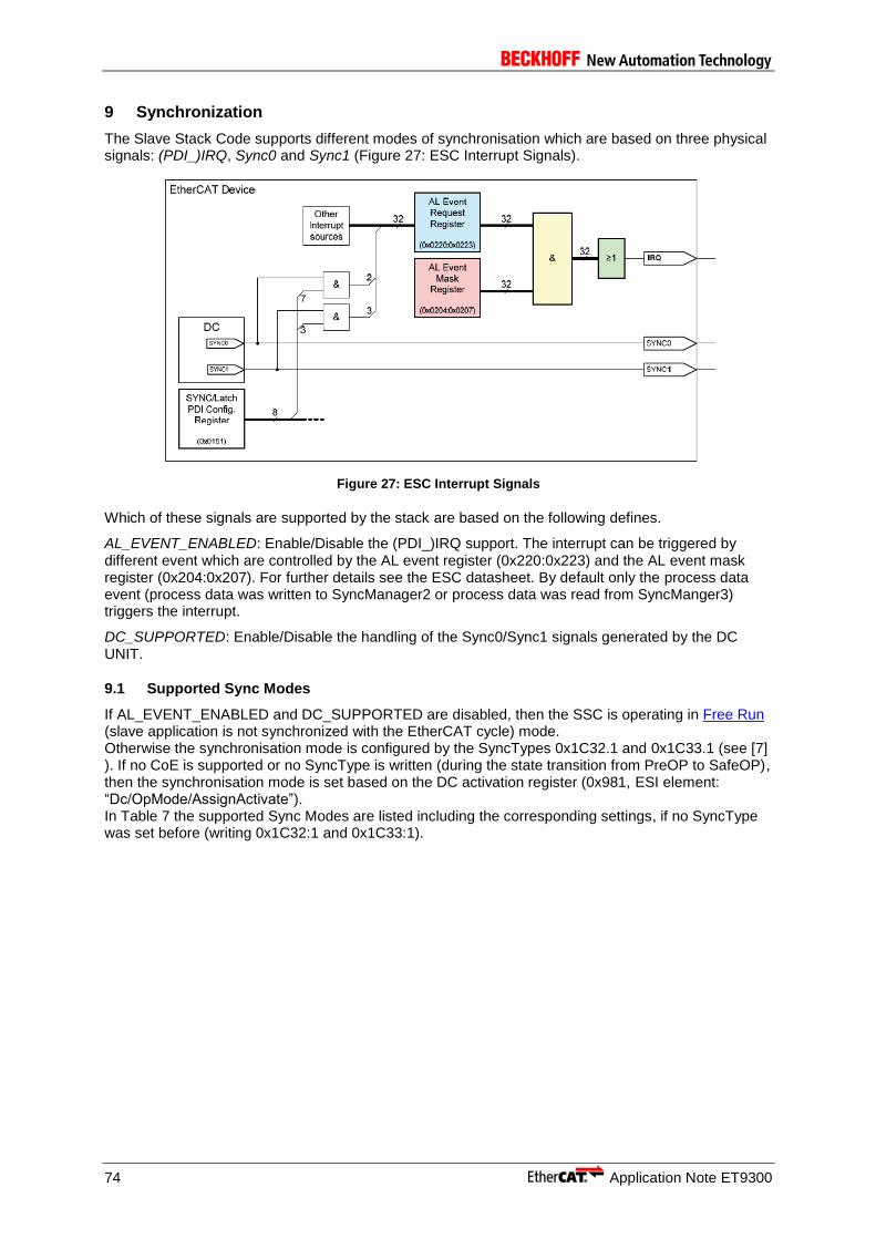
74 Application Note ET9300
9 Synchronization
The Slave Stack Code supports different modes of synchronisation which are based on three physical signals: (PDI_)IRQ, Sync0 and Sync1 (Figure 27: ESC Interrupt Signals).
Figure 27: ESC Interrupt Signals
Which of these signals are supported by the stack are based on the following defines.
AL_EVENT_ENABLED: Enable/Disable the (PDI_)IRQ support. The interrupt can be triggered by different event which are controlled by the AL event register (0x220:0x223) and the AL event mask register (0x204:0x207). For further details see the ESC datasheet. By default only the process data event (process data was written to SyncManager2 or process data was read from SyncManger3) triggers the interrupt.
DC_SUPPORTED: Enable/Disable the handling of the Sync0/Sync1 signals generated by the DC UNIT.
9.1 Supported Sync Modes
If AL_EVENT_ENABLED and DC_SUPPORTED are disabled, then the SSC is operating in Free Run (slave application is not synchronized with the EtherCAT cycle) mode. Otherwise the synchronisation mode is configured by the SyncTypes 0x1C32.1 and 0x1C33.1 (see [7] ). If no CoE is supported or no SyncType is written (during the state transition from PreOP to SafeOP), then the synchronisation mode is set based on the DC activation register (0x981, ESI element: “Dc/OpMode/AssignActivate”). In Table 7 the supported Sync Modes are listed including the corresponding settings, if no SyncType was set before (writing 0x1C32:1 and 0x1C33:1).

Application Note ET9300 75
Table 7: Supported Sync Modes
Sync Type AL_EVENT_ENABLED DC_SUPPORTED Sync0/1 Activation (Reg. 0x981)
Sync0 Cycle time (Reg. 0x9A0:0x9A3)
Sync1 Cycle time (Reg. 0x9A4:0x9A7)
Free Run* 0 -- Bit0:7: 0 --
SyncManager(SM) * 1 -- Bit0:7: 0 --
SM/Sync0* 1 1 Bit0: 1
Bit1: 1
Bit2:7: --
--
SM/Sync0/Sync1 1 1 Bit0: 1
Bit1: 1
Bit2: 1
Bit3:7: --
Sync0Cycle >= Sync1Cycle
Sync0* 0 1 Bit0: 1
Bit1: 1
Bit2:7: --
--
Sync0/Sync1 0 1 Bit0: 1
Bit1: 1
Bit2: 1
Bit3:7: --
--
Subordinated cycles 1 1 Bit0: 1
Bit1: 1
Bit2: 1
Bit3:7: --
Sync0Cycle < Sync1Cycle
*: Default sync type if no CoE is supported.
In the following chapters the supported synchronization modes are described. The terms and values in the figures are:
- PDO_OutputMapping(): Copies the output process data from the SM2 buffer to the local memory and calls APPL_OutputMapping(). See chapter 6 for further details.
- ECAT_Application(): Calls the function APPL_Application(). See chapter 6 for further details.
- PDO_InputMapping(): Calls the function APPL_InputMapping(). See chapter 6 for further details. Copy the input process data from the local memory to the SM3 buffer.
- 0x1C32.6 / 0x1C33.6 (Calc and Copy Time): Required time to copy the process data from the ESC to the local memory and calculate the output value. This can be defined by “PD_OUTPUT_CALC_AND_COPY_TIME” and “PD_INPUT_CALC_AND_COPY_TIME”. For further details see 9.2.
- 0x1C32.9 / 0x1C33.9 (Delay Time): Delay from receiving the trigger to set the output or latch the input. This can be defined by “PD_OUTPUT_DELAY_TIME” and “PD_INPUT_DELAY_TIME”.
- 0x1C32.2 / 0x1C33.2 (Cycle Time): When using DC synchronization the value is read from register 0x9A0:0x9A3. For further details see 9.2.
- 0x1C32.5 / 0x1C33.5 (Min Cycle Time): Minimum cycle time for the application. This can be specified by “MIN_PD_CYCLE_TIME”. It is the total execution time of all slave application related operations. In the SSC it is the PDO_OutputMapping(), ECAT_Application() and PDO_InputMapping(). For further details see 9.2.

76 Application Note ET9300
9.1.1 FreeRun
In this mode there is no slave application synchronisation (see Figure 28: Free Run). The function “PDO_OutputMapping()” is called only if new output process data is available.
Main Loop Start Main Loop Start
Outputs valid Inputs latch
PDO_OutputMapping() PDO_InputMapping()ECAT_Application()
Calc and Copy Time
(0x1C32.6)
Delay Time (0x1C32.9)
Calc and Copy Time
(0x1C33.6)
Delay Time (0x1C33.9)
Start Input Latch
Figure 28: Free Run
Free Run synchronization parameter: 0x1C32.1 = 0 0x1C33.1 = 0
9.1.2 SyncManager
In this mode the slave application is executed SyncManager synchronous (Figure 29: SyncManager Synchronization). On every write event to the output process data SyncManager (SM2) the slave application is started. If the device supports only inputs, then the application is started on reading the input process data (SM3).
SM2/3 Event SM2/3 Event
Outputs valid Inputs latch
PDO_OutputMapping() PDO_InputMapping()ECAT_Application()
Calc and Copy Time
(0x1C32.6)
Delay Time (0x1C32.9)
Calc and Copy Time
(0x1C33.6)
Delay Time (0x1C33.9)
Min Cycle Time (0x1C32.5/0x1C33.5)
Cycle Time (0x1C32.2/0x1C33.2)
Start Input Latch
Figure 29: SyncManager Synchronization
SyncManager synchronization parameter: 0x1C32.1 = 0x1 0x1C33.1 = 0x22
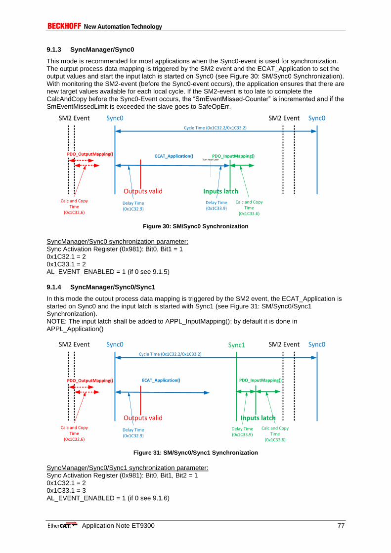
Application Note ET9300 77
9.1.3 SyncManager/Sync0
This mode is recommended for most applications when the Sync0-event is used for synchronization. The output process data mapping is triggered by the SM2 event and the ECAT_Application to set the output values and start the input latch is started on Sync0 (see Figure 30: SM/Sync0 Synchronization). With monitoring the SM2-event (before the Sync0-event occurs), the application ensures that there are new target values available for each local cycle. If the SM2-event is too late to complete the CalcAndCopy before the Sync0-Event occurs, the “SmEventMissed-Counter” is incremented and if the SmEventMissedLimit is exceeded the slave goes to SafeOpErr.
SM2 Event SM2 Event
Outputs valid Inputs latch
PDO_OutputMapping() PDO_InputMapping()ECAT_Application()
Calc and Copy Time
(0x1C32.6)
Delay Time (0x1C32.9)
Calc and Copy Time
(0x1C33.6)
Delay Time (0x1C33.9)
Cycle Time (0x1C32.2/0x1C33.2)
Sync0 Sync0
Start Input Latch
Figure 30: SM/Sync0 Synchronization
SyncManager/Sync0 synchronization parameter: Sync Activation Register (0x981): Bit0, Bit1 = 1 0x1C32.1 = 2 0x1C33.1 = 2 AL_EVENT_ENABLED = 1 (if 0 see 9.1.5)
9.1.4 SyncManager/Sync0/Sync1
In this mode the output process data mapping is triggered by the SM2 event, the ECAT_Application is started on Sync0 and the input latch is started with Sync1 (see Figure 31: SM/Sync0/Sync1 Synchronization). NOTE: The input latch shall be added to APPL_InputMapping(); by default it is done in APPL_Application()
SM2 Event SM2 Event
Outputs valid Inputs latch
PDO_OutputMapping() PDO_InputMapping()ECAT_Application()
Calc and Copy Time
(0x1C32.6)
Delay Time (0x1C32.9)
Calc and Copy Time
(0x1C33.6)
Delay Time (0x1C33.9)
Cycle Time (0x1C32.2/0x1C33.2)
Sync0 Sync0Sync1
Figure 31: SM/Sync0/Sync1 Synchronization
SyncManager/Sync0/Sync1 synchronization parameter: Sync Activation Register (0x981): Bit0, Bit1, Bit2 = 1 0x1C32.1 = 2 0x1C33.1 = 3 AL_EVENT_ENABLED = 1 (if 0 see 9.1.6)

78 Application Note ET9300
9.1.5 Sync0
In this mode the slave application is started on Sync0 (see Figure 32: Sync0 Synchronization). To reduce the jitter delay between Sync0 and Outputs valid, the preferred synchronization is SyncManager/Sync0 (see chapter 9.1.3).
Outputs valid Inputs latch
PDO_OutputMapping() PDO_InputMapping()ECAT_Application()
Calc and Copy Time
(0x1C32.6)
Delay Time (0x1C32.9)
Calc and Copy Time
(0x1C33.6)
Delay Time (0x1C33.9)
Min Cycle Time (0x1C32.5/0x1C33.5)
Cycle Time (0x1C32.2/0x1C33.2)
Sync0 Sync0
Frame Frame
Start Input Latch
Figure 32: Sync0 Synchronization
Sync0 synchronization parameter: Sync Activation Register (0x981): Bit0, Bit1 = 1 0x1C32.1 = 2 0x1C33.1 = 2 AL_EVENT_ENABLED = 0 (if 1 see 9.1.3)
9.1.6 Sync0/Sync1
The output process data mapping and the ECAT_Application is started on Sync0 and the input latch is started with Sync1 (Figure 33: Sync0/Sync1 Synchronization). NOTE: The input latch shall be added to APPL_InputMapping(); by default it is done in APPL_Application().
Outputs valid Inputs latch
ECAT_Application()PDO_OutputMapping() PDO_InputMapping()
Calc and Copy Time
(0x1C32.6)
Delay Time (0x1C32.9)
Calc and Copy Time
(0x1C33.6)
Delay Time (0x1C33.9)
Cycle Time (0x1C32.2/0x1C33.2)
Sync0 Sync0Sync1
Frame Frame
Figure 33: Sync0/Sync1 Synchronization
Sync0/Sync1 synchronization parameter: Sync Activation Register (0x981): Bit0, Bit1, Bit2 = 1 0x1C32.1 = 2 0x1C33.1 = 3 AL_EVENT_ENABLED = 0 (if 1 see 9.1.4)
9.1.7 Subordinated Cycles
In this mode the output process data mapping is triggered on the SM 2 event, the ECAT_Application is started on Sync1 and each subordinated cycle is triggered with Sync0 (Figure 34: Subordinated

Application Note ET9300 79
Cycles). The relation between Sync0 and the bus cycle is configured by the ESI element:CycleTimeSync0@Factor.
Possible Outputs valid
Possible Inputs latch
Calc and Copy Time
(0x1C32.6)
Delay Time (0x1C32.9)
Calc and Copy Time
(0x1C33.6)
Delay Time (0x1C33.9)
Sync0Sync1
PDO_OutputMapping()
SM2 Event
PDO_InputMapping()
Sync0 Cycle Time(0x1C32.10/0x1C33.10)
Cycle Time (0x1C32.02/0x1C33.02)
Sync0Sync1
Start Input Latch
ECAT_Application()
Sync0
ECAT_Application()
Sync0
ECAT_Application()
Sync0
ECAT_Application()
SM2 Event
Figure 34: Subordinated Cycles
Subordinated Cycles synchronization parameter: Sync Activation Register (0x981): Bit0, Bit1, Bit2 = 1 Sync0Cycle Time (0x9A0:0x9A3) < Sync1Cycle Time (0x9A4:0x9A7) 0x1C32.1 = 3 0x1C33.1 = 3 AL_EVENT_ENABLED = 1
9.2 Synchronization Timings
The configure the synchronization an EtherCAT slave may provide timing and delay information in the Sync Manager Parameter objects (0x1C3x). The Slave Stack Code provides two process data Sync Manager (SM2 handling the outputs and SM3 handling the inputs). Therefore the object 0x1C32 (related to SM2) and 0x1C33 (related to SM3) are defined.
The timings and delays in an SSC based slave application may either be fixed defined or calculated during runtime. The following values are provided:
Calc and Copy Time:
0x1C32.6: Runtime of the function “PDO_OutputMapping()”
Specified by: “PD_OUTPUT_CALC_AND_COPY_TIME”
0x1C33.6: Runtime of the function “PDO_InputMapping()”
Specified by: “PD_INPUT_CALC_AND_COPY_TIME”
Delay Time:
0x1C32.9: (Hardware) Delay to set the physical outputs
Specified by “PD_OUTPUT_DELAY_TIME”
0x1C33.9: (Hardware) Delay to latch the physical inputs
Specified by “PD_INPUT_DELAY_TIME”
Cycle Time:
0x1C32.2/0x1C33.2: In case of SM sync mode the minimum SM cycle is stored. In case of DC sync mode the Sync0 cycle time is stored
Min Cycle Time:
0x1C32.5/0x1C33.5: Minimum application cycle time (PDO_OutputMapping() + ECAT_Application() + PDO_InputMapping())
Specified by “MIN_PD_CYCLE_TIME”

80 Application Note ET9300
Except of the delay time (0x1C3x.9) all values can be measured. To enable the measurement the corresponding defines shall be set to 0 and the entry “Get Cycle Time” (0x1C3x.9) shall be set to 1. The measurement should only be enabled once in Operational to get the timings for the current configuration.
NOTE: The timing values are based on the System time register (0x910) therefore the DC Unit has to enabled.

Application Note ET9300 81
10 CiA402 drive profile
Since version 4.30 the Slave Stack Code contains a sample implementation of the CiA402 drive profile as described in [1] . This implementation provides the interface between the motion controller application and communication layer.
Following features are supported:
- CiA402 objects (see chapter 10.1 Objects)
- CiA402 state machine (see chapter 10.2 State machine)
- This implementation supports cyclic synchronous position (csp) and cyclic synchronous velocity (csv) operation modes.
CiA402 specific files:
cia402appl.c : CiA402 drive profile implementation
cia402appl.h : Drive profile specific objects, definitions and axes structures
All motion controller related values are encapsulated in structure TCiA402Axis (file:
cia402appl.h). The configuration parameters and error codes are directly mapped to the
corresponding objects. The process data objects are updated in the input/output mapping functions
(file: ecatappl.c). Currently the sample supports maximum of two axes. The axes are initialized in
the EtherCAT state change from PREOP to SAFEOP.
The motion controller is a simple integration, which just copies the target values to the actual values (see chapter 10.3 Operation modes).
10.1 Objects
All CiA402 specific objects are defined in file cia402appl.h.
All mandatory and some optional object are defined in this sample implementation. Table 8 contains a
list of all defined objects. The object variables are located in the structure CiA402Objects.
Table 8: Object definitions in file cia402appl.h
Index Object name Variable in source code Comment/Description
0x1600 Rx PDOs sRxPDOMap0 includes all objects required for dynamic change between csv/csp
0x1601 Rx PDOs sRxPDOMap1 includes objects required for csp mode of operation
0x1602 Rx PDOs sRxPDOMap2 includes objects required for csv mode of operation
0x1A00 Tx PDOs sTxPDOMap0 includes all objects required for dynamic change between csv/csp
0x1A01 Tx PDOs sTxPDOMap1 includes objects required for csp mode of operation
0x1A02 Tx PDOs sTxPDOMap2 includes objects required for csv mode of operation
0x1C12 SyncManger 2 PDO assign (Rx PDOs)
sRxPDOassign this object is written in change state from PREOP to SAFEOP; the configuration depends on the number of axes (not include in
CiA402Objects)
0x1C13 SyncManger 3 PDO assign (Tx PDOs)
sTxPDOassign equal to 0x1C12 (not include in
CiA402Objects)
0x603F Error Code objErrorCode this value shall be set if an error in the PDS occurs
82 Application Note ET9300
Index Object name Variable in source code Comment/Description
0x6040 Controlword objControlWord object for the output commands from the master
0x6041 Status word objStatusWord current axis status
0x605A Quick stop option code
objQuickStopOptionCode predefined ramp if an quick stop shall be performed
0x605B Shutdown option code
objShutdownOptionCode predefined action in state transition 8
0x605C Disable operation option code
objDisableOperationOptionCode predefined action in state transition 5
0x605E Fault reaction option code
objFaultReactionCode predefined action in state “Fault reaction active”
0x6060 Modes of operation
objModesOfOperation requested operation mode
0x6061 Modes of operation display
objModesOfOperationDisplay current operation mode
0x6064 Position actual value
objPositionActualValue current position value (delivered by encoder)
0x606C Velocity actual value
objVelocityActualValue velocity feedback
0x6077 Torque actual value
objTorqueActualValue currently not used (only for completion)
0x607A Target position objTargetPosition requested Postion value (set in csp mode)
0x607D Software position limit
objSoftwarePositionLimit includes the minimum and maximum actual position limit
0x6085 Quick stop declaration
objQuickStopDeclaration predefined action in state “Quick stop active”
0x60C2 Interpolation time period
objInterpolationTimePeriod
0x60FF Target velocity objTargetVelocity target velocity requested by the master
0x6502 Supported drive modes
objSupportedDriveModes list of all supported operation modes
The objects from 0x6000 to 0x67FF are incremented with 0x800 for each axis (Index + #Axis*0x800).
10.2 State machine
Figure 35 shows the state machine described in [1] . State changes are requested by setting 0x6040 (Controlword) or by a local event (if an error occurs). If the device is in state OP the transitions 0, 1 and 2 are skipped. The option codes next to the transition lines indicate that a specific action which shall be performed in of one of these state changes. All handled state transitions including the required Controlword, resulting state and corresponding functions are listed in Table 9: State machine. The bits 0,1,2,3 and 7 of the control word are taken into consideration in this sample implementation. Drive functions e.g.”Break applied” or “Axis function enabled” need to be activated or deactivated corresponding to the current state. In this sample these functions are handled by Boolean variables.
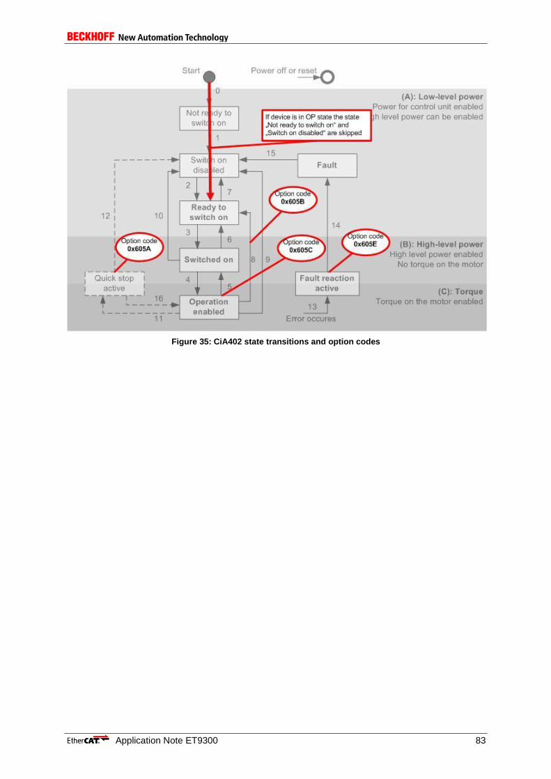
Application Note ET9300 83
Figure 35: CiA402 state transitions and option codes

84 Application Note ET9300
Table 9: State machine
The transition number in Table 8 referring to the transition number in Figure 35.[1]
10.3 Operation modes
In general this sample supports the csv and csp mode of operation. Each axis can be configured as csv, csp or combined controller via modules (Figure 36). In last case the mode of operation can be switch dynamically. For this reason all objects required for motion control are mapped to PDOs. In the current TwinCAT Version (2.11 build 1539) the NC task doesn’t provide a variable for the objects 0x6060 (Mode of operation) and 0x6061 (Mode of operation display), so these objects values need to be directly provided by the PLC.
The motion controller function (CiA402_DummyMotionControl()) just copies the target velocity
values to the actual velocity. The actual position is calculated by the actual velocity and the motion controller cycle time. If the device is in SM Sync mode the cycle time is calculated by an internal timer within the first application cycle. In DC Sync mode the cycle time is set to Sync0 cycle value.
Transition Control word bits Resulting state Variable (Function)
Bit 7
(fault re
set)
Bit 3
(enab
le o
pera
tion)
Bit 2
(quic
k s
top)
Bit 1
(enab
le v
olta
ge)
Bit 0
(sw
itch
on)
bB
rake
App
lied
bLow
Leve
lPow
er
App
lied
bH
ighL
evelP
ow
er
App
lied
bA
xis
Fu
nctio
n
Ena
ble
d
bC
on
figura
tion
Allo
wed
3 0 x 1 1 1 Switched on true true true false true
4 0 1 1 1 1 Operation enabled
false true true true false
5 0 0 1 1 1 Switch on true true true false true
6 0 x 1 1 0 Ready to switch on
true true false false true
7 0 x x 0 x Switch on disabled
true true false false true
0 x 0 1 x
8 0 x 1 1 0 Ready to switch on
true true false false true
9 0 x x 0 x Switch on disabled
true true false false true
10 0 x x 0 x Switch on disabled
true true false false true
0 x 0 1 x
11 0 x 0 1 x Quick stop active false true true true false
12 0 x x 0 x Switch on disbaled
true true false false true
13 Triggered by application Fault reaction active
false true true true false
14 Transition if option code 0x605E is finished
Fault true true false false true
15 1 x x x x Switch on disabled
true true false false true
16 After quick stop always goto “Switch on disabled”
(Operation enabled)
false true true true false
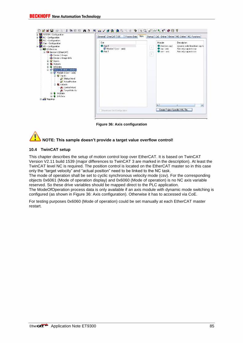
Application Note ET9300 85
Figure 36: Axis configuration
NOTE: This sample doesn’t provide a target value overflow control!
10.4 TwinCAT setup
This chapter describes the setup of motion control loop over EtherCAT. It is based on TwinCAT Version V2.11 build 1539 (major differences to TwinCAT 3 are marked in the description). At least the TwinCAT level NC is required. The position control is located on the EtherCAT master so in this case only the “target velocity” and “actual position” need to be linked to the NC task. The mode of operation shall be set to cyclic synchronous velocity mode (csv). For the corresponding objects 0x6061 (Mode of operation display) and 0x6060 (Mode of operation) is no NC axis variable reserved. So these drive variables should be mapped direct to the PLC application. The ModeOfOperation process data is only available if an axis module with dynamic mode switching is configured (as shown in Figure 36: Axis configuration). Otherwise it has to accessed via CoE.
For testing purposes 0x6060 (Mode of operation) could be set manually at each EtherCAT master restart.

86 Application Note ET9300
Figure 37: Set device variable without PLC link
10.4.1 Automatic network setup
The TwinCAT System Manger provides a comfortable master setup.
a. TwinCAT 2: Open a new System Manager configuration and scan the network for new devices (Figure 38).
Figure 38: Scan for new EtherCAT devices with TwinCAT 2
b. TwinCAT 3: Open the Visual Studio shell, create a new TwinCAT project and scan the network for new devices (Figure 27).

Application Note ET9300 87
Figure 39: Scan for new EtherCAT devices with TwinCAT 3
After the network scan is complete a message box appears with a notification that an EtherCAT drive was found. If the this message is acknowledged with “Yes” the System Manager will automatically create an NC task with the correct process data mapping.
10.4.2 Manual network setup
First add a NC task including a CiA402 Axis to the NC configuration.
a. TwinCAT 2 : Add NC task ->Add continuous Axis -> set Axis type to “CANopen DS402” (see Figure 40).
Figure 40: TwinCAT 2 CiA402 axis setup
a. TwinCAT 3 : Open the context menu of the MOTION TreeItem -> “Add New Item” -> Type “NC/PTP NCI Configuration” -> Open the context menu of the new created “Axes” TreeItem -> “Add New Item” -> Type “Continuous Axis” -> set Axis type to “CANopen DS402” (see Figure 41: TwinCAT 3 CiA402 axis setup).

88 Application Note ET9300
Figure 41: TwinCAT 3 CiA402 axis setup
Add a new EtherCAT device and append the CiA402 description (Figure 42).
Figure 42: Add CiA402 device
Now the device variables (objects) need to be linked to the axis variables as shown in Table 10.
Table 10: Linking of device and NC variables
object index Type variable name
device NC axis
0x6040 output Controlword “Drive_Out” -> “nCtrl1” + “nCtrl2”
0x60FF output Target velocity “Drive_Out” -> “nOutData2”
0x6041 input Statusword “Drive_In” -> ”nStatus1” + “nStatus2”
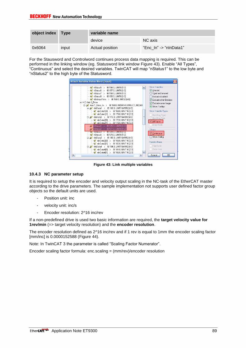
Application Note ET9300 89
object index Type variable name
device NC axis
0x6064 input Actual position “Enc_In” -> “nInData1”
For the Stausword and Controlword continues process data mapping is required. This can be performed in the linking window (eg. Statusword link window Figure 43). Enable “All Types”, “Continuous” and select the desired variables. TwinCAT will map “nStatus1” to the low byte and “nStatus2” to the high byte of the Statusword.
Figure 43: Link multiple variables
10.4.3 NC parameter setup
It is required to setup the encoder and velocity output scaling in the NC-task of the EtherCAT master according to the drive parameters. The sample implementation not supports user defined factor group objects so the default units are used.
- Position unit: inc
- velocity unit: inc/s
- Encoder resolution: 2^16 inc/rev
If a non-predefined drive is used two basic information are required, the target velocity value for 1rev/min (=> target velocity resolution) and the encoder resolution.
The encoder resolution defined as 2^16 inc/rev and if 1 rev is equal to 1mm the encoder scaling factor [mm/inc] is 0.0000152588 (Figure 44).
Note: In TwinCAT 3 the parameter is called “Scaling Factor Numerator”.
Encoder scaling factor formula: enc.scaling = (mm/rev)/encoder resolution
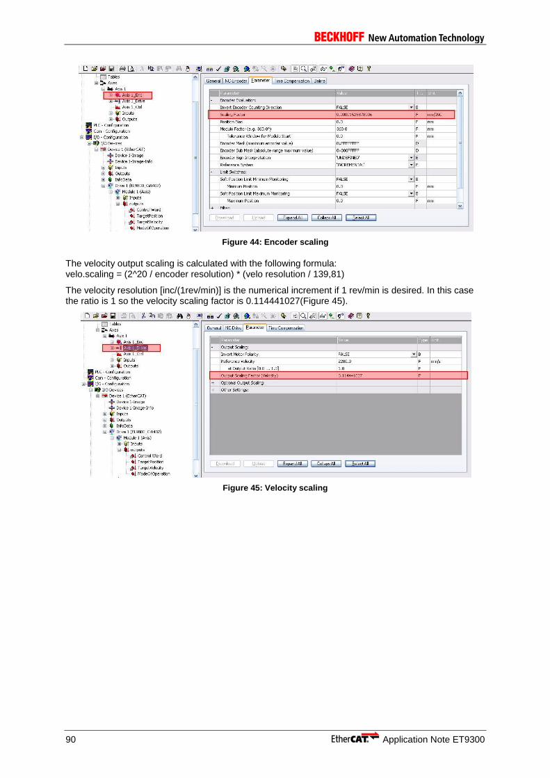
90 Application Note ET9300
Figure 44: Encoder scaling
The velocity output scaling is calculated with the following formula: velo.scaling = (2^20 / encoder resolution) * (velo resolution / 139,81)
The velocity resolution [inc/(1rev/min)] is the numerical increment if 1 rev/min is desired. In this case the ratio is 1 so the velocity scaling factor is 0.114441027(Figure 45).
Figure 45: Velocity scaling

Application Note ET9300 91
11 TestApplication
The test application is a specific slave stack which provides most of the specified EtherCAT slave features and also a mechanism to generate a slave behavior (also behavior which is not conform to the standard). This may be used to check master behavior with incorrect slave behavior.
This chapter is dealing with the possible configurations. The possible (mis)behaviors are organized within CoE objects in the index range from 0x2000 to 0x2FFD (Table 11 and Table 12).
In object 0x8000 the stack configuration is listed (SDO info need to be supported by EtherCAT master).
A release build of the test application for the EL9800 EtherCAT Evaluation board is located in “SSC_Vxixx/hex”. To create new test application slave files select the test application configuration in the SSC Tool.
Table 11: Test Object
Attribute Value
Index 0x2000 to 0x2FFD
Name Test object
Object Code RECORD
Max SubIndex 1-255
Table 12: Test Object Entry
Sub-Index
Description Data Type Access
PDO Mapping
Description / Default value
n (equal for every test)
Control/Counter
UNSIGNED16
RW/R No Control the test behavior
Bit0 enable/disable the test 0: Test disabled 1: Test enabled
Bit1 -7 Reserved for future use
Bit8-15 Counter (indicates the number of test executions)
11.1 Slave Behavior Control
Three possibilities are available to control the slave behavior either updating the enable/disable bit of the test object directly (Table 12: Test Object Entry), or via the Test Control object (Chapter 11.1.1) or by updating the ESC register 0xF80:0xF83 (Chapter 11.1.2).
11.1.1 Test Control Object
The Test Control object structure (Table 13 and Table 14) is similar to the PDO mapping objects. Every Subindex (entry) of the test control object maps an enable/disable function (Bit 0) to a physical digital input of the slave device.
If the application is compiled for the EL9800_4 EtherCAT Evaluation Kit the control object contains 7 entries (SI1-7) which are mapped to the switches 2 to 8 (switch 1 is a global test function enable switch). If the stack is not compiled for the EL9800 the control element contains 16 Entries which are mapped to the GPO register (0xF10:0xF11).
Table 13: Test Control Object
Attribute Value
Index 0x2FFF
Name Test control object

92 Application Note ET9300
Attribute Value
Object Code ARRAY
Max SubIndex 16 (7if build for EL9800)
Table 14: Test Control Object Entries
Sub-Index
Description
Data Type Access
PDO Mapping
Description / Default value
1 – Max SubIndex (see Table 13)
Linked test object entry
UNSIGNED32
RW No Linked test object entry
Bit0 – 7
Reserved for future use
Bit8 -15
Subindex of the test object entry
Bit16-32
Index of the test object
11.1.2 User RAM 0xF80:0xF83
The master can write the object index and subindex of the behavior to be activated to the register (Table 15: Test Application | ESC Register 0xF80:0xF83). The value is read by the application on a state trigger from INIT to any (also INIT to INIT), if the behavior is accepted the first bit in 0xF83 is set.
Table 15: Test Application | ESC Register 0xF80:0xF83
11.2 ESM Tests (0x2000 – 0x200F)
Table 16: Test Object 0x2000 (ESM Group 1)
Bit Description Purpose
0:15 Object Index Updated by the master
16:23 Subindex Updated by the master
24 1 : behavior active Shall be set to 0 by the master if a new index/subindex was written. Is set to 1 by the slave application
32:31 Reserved for future use
Sub-Index
Description Purpose
1 Invalid state transition from INIT to PreOP AL status Code 0x16 (Invalid Mailbox)
2 Invalid state transition from PreOP to SafeOP AL status Code 0x1D (Invalid Output SyncManager config)
3 Invalid state transition from PreOP to SafeOP AL status Code 0x1E (Invalid Input SyncManager config)
4 Do not unlock the SM3 (process data input SyncManager) buffer during the transition from PreOP to SafeOP.
Check if the Master starts the process data communication without initial input process data.

Application Note ET9300 93
11.3 Mailbox Tests (0x2010 – 0x201F)
Table 17: Test Object 0x2010 (Mailbox Group 1)
11.4 CoE Tests (0x2020 – 0x202F)
Table 18: Test Object 0x2020 (CoE Group 1)
5 Acknowledge state requests not directly. ECAT_StateChange() is used.
Sub-Index
Description Purpose
1 Check if the master mailbox counter is always incremented by 1. If not a mailbox error will be returned.
Check if the EtherCAT master sends the correct mailbox counter sequence.
2 Change the slave mailbox counter in alternating order. The mailbox counter may also have the value 0 after it was incremented.
An EtherCAT master should also handle a mailbox counter sequence unequal an increment by one.
Sub-Index
Description Purpose
1 On SDO upload and SDO Info List request a maximum mailbox size of 16Bytes is used.
Decouple physical mailbox size from mailbox data length.
2 Create diagnosis message on every state change.
3 Create diagnosis message with every application cycle.
4 “simulate” huge object dictionary. The number of objects is specified by “DUMMY_OD_LENGTH” (default 1000). All objects have the index 0x1000
This behavior is used to test the List segmentation handling of the master and SSC.
5 Return on SDO upload with complete access always the full object data based on MAX Subindex ( Value of SI0 is ignored)
6 Send an emergency on any SDO request in SafeOP
7 Pending SDO response on a SDO upload or download on 0x3006.0.
The request will be answered when a FoE read request for file “UnlockSdoResp” is received or in case that the mailbox queue is not supported on the next received mbx request.
Check correct pending SDO request handling.
8 Send an EoE ARP on all SDO access (upload/info/download) on 0x1009
9 Send an invalid mailbox data on all SDO access (upload/info/download) on 0x1009

94 Application Note ET9300
11.5 FoE Tests (0x2030 – 0x203F)
Table 19: Test Object 0x2030 (FoE Group 1)
11.6 Generic Objects
The objects described in this chapter are used to test the correct SDO handling by the slave and the master. Table 20: Generic Objects includes all defined objects.
Table 20: Generic Objects
Sub-Index
Description Purpose
1 Return an FoE Busy on a FoE Read request
Index / Subindex
Daftype / Code
Access Description Purpose
0x3001 RECORD / REC
RW
SI1 REAL32 Default value: 0xBABABABA
SI2 REAL64 Default value: 0xBABABABABABABABA
SI3 UINT64 Default value: 0xBABABABABABABABA
SI4 INT64 Default value: 0xBABABABABABABABA
0x3002 UINT32 / VAR
RW Default value: 0xBABABABA
0x3003 RECORD / REC
Includes base dataypes less or equal 1Byte.
SI1 BOOLEAN RW Default value: TRUE
SI2 BIT1 RW Default value:0x0
SI3 BIT2 RW Default value:0x3
SI4 BIT3 RW Default value:0x5
SI5 1BIT Align Next entry shall start at an Byte border
SI6 BIT4 Read; Write in Op and PreOP
Default value:0xA
SI7 4BIT Align Next entry shall start at an Byte border
SI8 BIT5 RW Default value:0x1A
SI9 3BIT Align Next entry shall start at an Byte border
SI10 BIT6 RW Default value:0x2A

Application Note ET9300 95
SI11 2BIT Align Next entry shall start at an Byte border
SI12 BIT7 RW Default value:0x6A
SI13 1BIT Align Next entry shall start at an Byte border
SI14 BIT8 Read;
Write in PreOP
Default value:0xFF
SI15 UINT8 Read;
Write in SafeOP
Default value:0xAA
SI16 INT8 Read;
Write in OP
Default value:0xBB
0x3004 RECORD / REC
Object to test alignment, empty entries and several access rights
SI1 UINT16 RO Default value:0x1122
SI2 UINT16 RW Default value:0x3344
SI3 UINT16 WO Default value:0x5566
SI4 BIT8 Write;
Read in PreOP
Default value:0x77 Datatype BIT8 is used because to “group” them into one 16Bit block (in case of an 16 or 32 Bit Controller the Alignment entry and Bit types are based on unsigned short)
SI5 8Bit Align
SI6 Empty
SI7 8Bit Align
SI8 UINT8 RO Default value:0x88
SI9 BIT2 WO Default value:0x1
SI10 BIT2 Write;
Read in SafeOP
Default value:0x2
SI11 2BIT Align
SI12 BIT2 RO Default value:0x3
SI13 BOOLEAN RW Default value TRUE
SI14 BIT7 Write;
Read in OP
Default value: 0 A single access to this entry will always return the SDO Abort Code 0x08000021 (Data cannot be read or stored because of local control)
0x3005 RECORD / REC
Uses two enum definitions:
0x800: Signed/unsigned presentation
0x801: Boolean
Generic enum test and test access to byte aligned enum definitions
SI1 0x800 RW Default value : “signed presentation”
96 Application Note ET9300
SI2 0x801 RW Default Value: “True”
SI3 10BIT Align
SI4 0x802 RW Default Value “Two Hundred”
0x3006 OCTET_STRING / VAR
RW The object size is 349 Byte. If a 128 Bytes mailbox is used the object is transmitted with one complete and two segmented services minus one Byte. Default value: Each Byte is incremented by one (starts with 0x00)
This object is used to test the mailbox unlock mechanism within the slave stack and the correct segmented handling by the master.
0x3007 BIT3/ARRAY
RW BIT3 array with 5 elements
0x3008 RECORD / REC
Includes set of Array base data types (e.g. BITARR32)
SI1 OCTET_STRING
RW UINT8 Array with four elements
SI2 UNICODE_STRING
RW UINT16 Array with two elements
SI3 ARRAY_OF_SINT
RW INT8 Array with four elements
SI4 ARRAY_OF_INT
RW INT16 Array with two elements
SI5 ARRAY_OF_DINT
RW INT32 Array with one element
SI6 ARRAY_OF_UDINT
RW UINT32 Array with one element
SI7 BITARR32 RW 32Bit Array
SI8 BITARR16 RW 16BitArray
SI8 BITARR8 RW 8BitArray
0x3009 OCTET_STRING / ARRAY
Huge Array Object. This object is used to test huge object handling in the master
SI1 –
254
OCTET_STRING
RW The first WORD of SI1 contains the Bitlength of each entry. The value can also be updated by single WORD access to SI1 all other write access will be ignored (no SDO Abort returned). The uploaded data will always be 0xBA.
0x300A RECORD / REC
Huge Record Object Within the SSC it is handled equal to
This object is used to test huge object handling in the master

Application Note ET9300 97
0x3009 only the object code is changed.
SI1 –
254
OCTET_STRING
RW The first WORD of SI1 contains the Bitlength of each entry. The value can also be updated by single WORD access to SI1 all other write access will be ignored (no SDO Abort returned). The uploaded data will always be 0xBA.
0x300B RECORD / REC
Byte Arrays with odd word length
Test correct complete access handling of byte array entries with odd word length.
SI1 OCTET_STRING
RW Default value : “12345”
SI2 UINT8 RO Default value : 0x66
SI3 OCTED_STRING
RW Default value : 0x77 – 0xBB
SI4 UINT8 RW Default value : 0xCC
0x300C VAR Max entry size object Test behavior if the entry size is > 65535
0x300D RECORD / REC
Slave-to-Slave test object
Test the Slave - to- Slave communication by sending an SDO upload on 0x1018.2 to a specific slave
SI1 UINT16 RW Destination slave address
EtherCAT address of the destination slave.
SI2 UINT8 RW Command If 1 is written an SDO upload on 0x1018.2 is generated.
SI3 UINT8 RO Status 1 : The SDO upload is generated
2 : The SDO upload response was received and written to SI4
SI4 UINT32 RO IdentValue Value of 0x1018.2 from the slave addressed in SI1.
0x300E RECORD / REC
si0_rw sin_ro test object
SI1 – 3 UINT16 RO
0x300F UINT16 / REC
si0_rw sin_ro test object
SI1 – 3 UINT16 RO
0x3010 RECORD / REC
si0_ro sin_wo test object
SI1 - 3 UINT16 WO
0x3012 RECORD / REC
Record with SI0 = 0

98 Application Note ET9300
SI1 - 3 RO
0x3013 BITARR32/VAR
RW
0x3014 BITARR16/VAR
RW
0x3015 BITARR8/VAR
RW
0x3016 RECORD / REC
RW empty record object
0x3017 OCTED_STRING / VAR
RW EoE Send Data the written data is send via EoE to the master back (only supported if MAILBOX QUEUE and dynamic memory allocation is available)
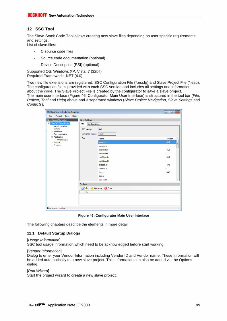
Application Note ET9300 99
12 SSC Tool
The Slave Stack Code Tool allows creating new slave files depending on user specific requirements and settings. List of slave files:
- C source code files
- Source code documentation (optional)
- Device Description (ESI) (optional)
Supported OS: Windows XP, Vista, 7 (32bit) Required Framework: .NET (4.0)
Two new file extensions are registered: SSC Configuration File (*.escfg) and Slave Project File (*.esp). The configuration file is provided with each SSC version and includes all settings and information about the code. The Slave Project File is created by the configurator to save a slave project. The main user interface (Figure 46: Configurator Main User Interface) is structured in the tool bar (File, Project, Tool and Help) above and 3 separated windows (Slave Project Navigation, Slave Settings and Conflicts).
Figure 46: Configurator Main User Interface
The following chapters describe the elements in more detail.
12.1 Default Startup Dialogs
[Usage Information] SSC tool usage information which need to be acknowledged before start working.
[Vendor Information] Dialog to enter your Vendor Information including Vendor ID and Vendor name. These Information will be added automatically to a new slave project. This information can also be added via the Options dialog.
[Run Wizard] Start the project wizard to create a new slave project.

100 Application Note ET9300
12.2 Main User Interface Elements
12.2.1 Tool Bar
12.2.1.1 File
The file menu (Figure 47: Configurator File Menu) contains the project file operations.
Figure 47: Configurator File Menu
[New] Create a new slave project based on the local SSC files. The project can either be created on the default configuration or a custom configuration (Figure 48: Create New Project). To import third party configurations see 12.6.
Figure 48: Create New Project
[Open] Open an existing project file.
[Save] Save the actual settings to the current project file (if no project file was created before a file browser dialog appears to create a new file).
[Save As] Save the actual settings to a new project file.
[Exit] Close current session.
12.2.1.2 Project
Figure 49: Configurator Project Menu
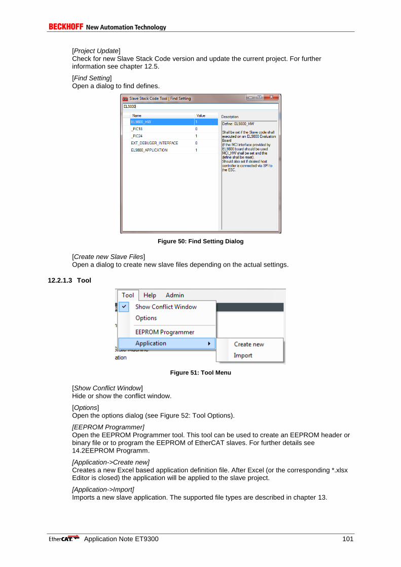
Application Note ET9300 101
[Project Update] Check for new Slave Stack Code version and update the current project. For further information see chapter 12.5.
[Find Setting] Open a dialog to find defines.
Figure 50: Find Setting Dialog
[Create new Slave Files] Open a dialog to create new slave files depending on the actual settings.
12.2.1.3 Tool
Figure 51: Tool Menu
[Show Conflict Window] Hide or show the conflict window.
[Options] Open the options dialog (see Figure 52: Tool Options).
[EEPROM Programmer] Open the EEPROM Programmer tool. This tool can be used to create an EEPROM header or binary file or to program the EEPROM of EtherCAT slaves. For further details see 14.2EEPROM Programm.
[Application->Create new] Creates a new Excel based application definition file. After Excel (or the corresponding *.xlsx Editor is closed) the application will be applied to the slave project.
[Application->Import] Imports a new slave application. The supported file types are described in chapter 13.
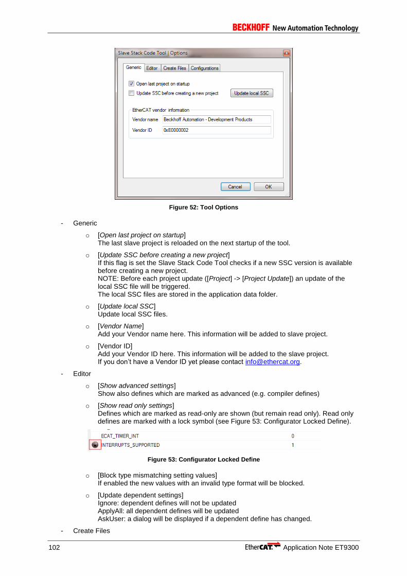
102 Application Note ET9300
Figure 52: Tool Options
- Generic
o [Open last project on startup] The last slave project is reloaded on the next startup of the tool.
o [Update SSC before creating a new project] If this flag is set the Slave Stack Code Tool checks if a new SSC version is available before creating a new project. NOTE: Before each project update ([Project] -> [Project Update]) an update of the local SSC file will be triggered. The local SSC files are stored in the application data folder.
o [Update local SSC] Update local SSC files.
o [Vendor Name] Add your Vendor name here. This information will be added to slave project.
o [Vendor ID] Add your Vendor ID here. This information will be added to the slave project. If you don’t have a Vendor ID yet please contact [email protected].
- Editor
o [Show advanced settings] Show also defines which are marked as advanced (e.g. compiler defines)
o [Show read only settings] Defines which are marked as read-only are shown (but remain read only). Read only defines are marked with a lock symbol (see Figure 53: Configurator Locked Define).
Figure 53: Configurator Locked Define
o [Block type mismatching setting values] If enabled the new values with an invalid type format will be blocked.
o [Update dependent settings] Ignore: dependent defines will not be updated ApplyAll: all dependent defines will be updated AskUser: a dialog will be displayed if a dependent define has changed.
- Create Files
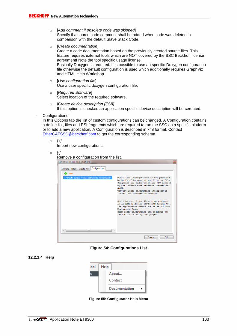
Application Note ET9300 103
o [Add comment if obsolete code was skipped] Specify if a source code comment shall be added when code was deleted in comparison with the default Slave Stack Code.
o [Create documentation] Create a code documentation based on the previously created source files. This feature requires external tools which are NOT covered by the SSC Beckhoff license agreement! Note the tool specific usage license. Basically Doxygen is required. It is possible to use an specific Doxygen configuration file otherwise the default configuration is used which additionally requires GraphViz and HTML Help Workshop.
o [Use configuration file] Use a user specific doxygen configuration file.
o [Required Software] Select location of the required software.
o [Create device description (ESI)] If this option is checked an application specific device description will be cereated.
- Configurations In this Options tab the list of custom configurations can be changed. A Configuration contains a define list, files and ESI fragments which are required to run the SSC on a specific platform or to add a new application. A Configuration is described in xml format. Contact [email protected] to get the corresponding schema.
o [+] Import new configurations.
o [-] Remove a configuration from the list.
Figure 54: Configurations List
12.2.1.4 Help
Figure 55: Configurator Help Menu

104 Application Note ET9300
[About] Show information about the SSC Tool.
[Contact] Create a new email to [email protected] with your standard email client.
[Documentation] List of SSC related documents
12.2.2 Windows
I. [Slave Project Navigation] The Slave Project Navigation window lists all kinds of defines which can be configured. Selecting one of the nodes, the corresponding defines are displayed in the Slave Settings window. If the project was saved at least once the root node name is equal to the project name. This window also supports Drag & Drop.
[Slave Settings] The information shown in this window depends on the selected node in the Slave Project Navigation window. If the root project node is selected the SSC Version, Config File Version, a list of all Slave Stack Code files and user files are shown (see Figure 56: Configurator Project Information). The file list within provides a right-click context menu (see Figure 57: Configurator File Context Menu).
.
Figure 56: Configurator Project Information
Figure 57: Configurator File Context Menu
[Reload File] Cached file will be reloaded (only possible for user files).
[Remove File] Remove file from project (only possible for user files).

Application Note ET9300 105
[Add File(s)] Add one or more files to the project. These files will not evaluated and just copied to the output folder. If a new hardware access file is add it can be included to the generic files by define “HW_ACCESS_FILE” in the hardware settings (e.g. “#include “myhw.h””). If a new application file is add also add the reference to “APPLICATION_FILE” (e.g. “#include “myappl.h””). NOTE: “Advanced Editor settings need to be activated to edit the file reference settings.
Edit File (double click on file) To Edit a user specific source file double click on the file. The default editor for this file type will be open.
If one of the setting nodes are selected within the Slave Project Navigation, the corresponding settings are displayed within the Slave Settings window (Figure 58: Configurator Slave Settings).
Figure 58: Configurator Slave Settings
II. Conflict Window This window displays conflicts of defines. Conflicts are distinguished between errors, warnings and information. Conflicting defines are denoted by the corresponding conflict symbol. NOTE: Not every combination of defines is checked. So it is up to the user to create a logical configuration.
[Error] Indicate that the configurator cannot create a valid slave stack with the actual configuration. [Warning] The defines marked with the warning symbol should be checked before creating new slave files. [Info] Additional information about the current configuration.
12.3 Create Files
Creating new files is the last step to create a new slave stack. The dialog is opened by selecting [Project] -> [Create new Slave Files].
a) Select output folder.
b) [Start] Start creating new files.
c) Output window dumps progress information.

106 Application Note ET9300
Figure 59: Configurator Create Files
[Cancel] Close dialog without creating new files
[Close] Close dialog when new files were created.
[Start] Create new slave files in the specified folder.
After new slave files are created a dialog appears to open the specified output folder or to return to the configurator.
12.4 Local SSC Update
Each new project is based on the local Slave Stack Code files. These files will be updated before a project update is started or when a new project is created (if this option is set). The Slave Stack Code files are stored in application folder of the SSC Tool. The update dialog is shown in Figure 60: Configurator Slave Stack Code Update.
Figure 60: Configurator Slave Stack Code Update
[online] Load SSC files from the Beckhoff FTP server.

Application Note ET9300 107
[offline] Load SSC files from a local SSC zip archive.
Both options require an external archive tool (7-Zip, WinRAR® or WinZip®).
12.5 Project Update
The SSC Tool provides the possibility to update generic files within the current project to the latest version. If new files are available the update dialog is show (Figure 61: Configurator Project Update Dialog).
Figure 61: Configurator Project Update Dialog
[Current version] Slave Stack Code version of the current project
[New version] Latest Slave Stack Code version available
[Show only current project related changes] If checked only changes are shown which are related to the current project settings. Otherwise all changes are displayed. NOTE: If checked only the latest changes are shown. Related changes which are older than one version are not displayed.
[OK] Update current project. If an exclamation mark is show important information need to be acknowledged before the project is updated.
[Cancel] Cancel project update
12.6 Import Configurations
A configuration offers the possibility to manipulate SSC settings, to reference source files and add new elements ESI. By default a series of application-related configurations are available, but it is also possible to import new e.g. a configuration for the Texas Instruments AM335x.

108 Application Note ET9300
Importing a Configuration can either be done via the new project dialog (Figure 62: New Project | Import Configuration) or the options menu (Figure 63: Options | Import Configuration).
Figure 62: New Project | Import Configuration
Figure 63: Options | Import Configuration
NOTE: a Configuration may reference files which are not covered by the Beckhoff Automation GmbH license agreement. Contact the configuration vendor for further information.
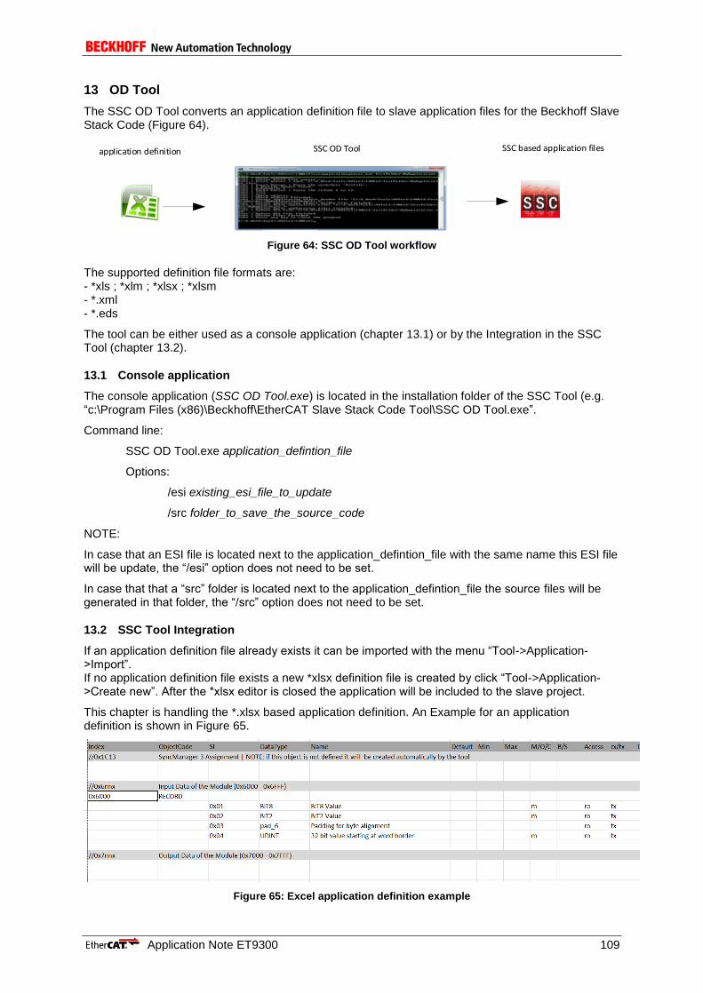
Application Note ET9300 109
13 OD Tool
The SSC OD Tool converts an application definition file to slave application files for the Beckhoff Slave Stack Code (Figure 64).
SSC based application filesapplication definition SSC OD Tool
Figure 64: SSC OD Tool workflow
The supported definition file formats are: - *xls ; *xlm ; *xlsx ; *xlsm - *.xml - *.eds
The tool can be either used as a console application (chapter 13.1) or by the Integration in the SSC Tool (chapter 13.2).
13.1 Console application
The console application (SSC OD Tool.exe) is located in the installation folder of the SSC Tool (e.g. “c:\Program Files (x86)\Beckhoff\EtherCAT Slave Stack Code Tool\SSC OD Tool.exe”.
Command line:
SSC OD Tool.exe application_defintion_file
Options:
/esi existing_esi_file_to_update
/src folder_to_save_the_source_code
NOTE:
In case that an ESI file is located next to the application_defintion_file with the same name this ESI file will be update, the “/esi” option does not need to be set.
In case that that a “src” folder is located next to the application_defintion_file the source files will be generated in that folder, the “/src” option does not need to be set.
13.2 SSC Tool Integration
If an application definition file already exists it can be imported with the menu “Tool->Application->Import”. If no application definition file exists a new *xlsx definition file is created by click “Tool->Application->Create new”. After the *xlsx editor is closed the application will be included to the slave project.
This chapter is handling the *.xlsx based application definition. An Example for an application definition is shown in Figure 65.
Figure 65: Excel application definition example

110 Application Note ET9300
The slave application data is organized in objects (see chapter 7). Only objects in the manufacturer specific range 0x2000 – 0x5FFF and the profile specific range 0x6000 – 0x9FFF shall be defined. The communication specific objects are generated automatically or they are configured via the SSC Tool.
13.3 PDO mapping and SM assign objects
The PDO mapping and SyncManager assign objects are generated automatically according the Modular Device Profile (MDP), as defined in ETG.5001-1 (Since ETG.5003 Semiconductor Device Profile uses the MDP structure, the tool also generated the objects for such object dictionaries). Mapping and Assign object generation is described in Table 21.
Table 21: PDO mapping and SM assign object generation
For profiles like CiA402 input objects and output objects are all mapped into one single input and output PDO.
13.3.1 Manual PDO mapping and SM assign description
In case that a manual PDO mapping and/or SM assignment is needed (e.g. in case of an expected padding within the process data) these object can be defined as shown in Figure 66.
Figure 66: Maunal definition of PDO mapping and SM assign objects
Index range
0x2000 – 0x5FFF
Objects are added to the online and offline OD, but they are not added to the mapping objects
0x6FFF – 0x9FFF
Mapping and Assign rules apply, e.g.
0x6000 0x1A00 0x1C12:01
0x6010 0x1A01 0x1C12:02
0x6011 0x1A01
0x6020 0x1A02
…
0x7000 0x1600 0x1C13:01
0x7010 0x1601 0x1C13:02
0x7020 0x1602 0x1C13:03
….
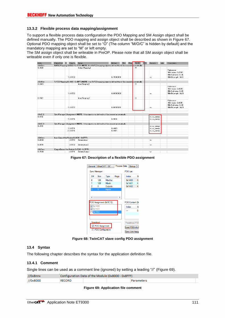
Application Note ET9300 111
13.3.2 Flexible process data mapping/assignment
To support a flexible process data configuration the PDO Mapping and SM Assign object shall be defined manually. The PDO mapping and assign object shall be described as shown in Figure 67. Optional PDO mapping object shall be set to “O” (The column “M/O/C” is hidden by default) and the mandatory mapping are set to “M” or left empty. The SM assign object shall be writeable in PreOP. Please note that all SM assign object shall be writeable even if only one is flexible.
Figure 67: Description of a flexible PDO assignment
Figure 68: TwinCAT slave config PDO assignment
13.4 Syntax
The following chapter describes the syntax for the application definition file.
13.4.1 Comment
Single lines can be used as a comment line (ignored) by setting a leading “//” (Figure 69).
Figure 69: Application file comment
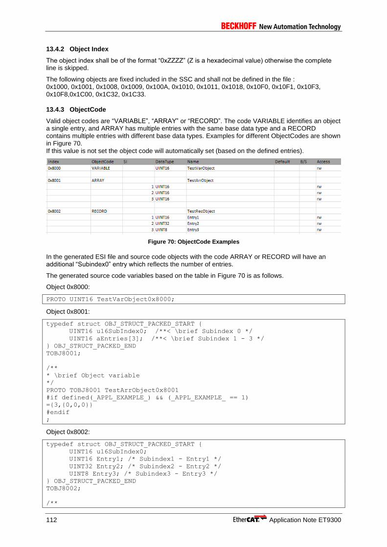
112 Application Note ET9300
13.4.2 Object Index
The object index shall be of the format “0xZZZZ” (Z is a hexadecimal value) otherwise the complete line is skipped.
The following objects are fixed included in the SSC and shall not be defined in the file : 0x1000, 0x1001, 0x1008, 0x1009, 0x100A, 0x1010, 0x1011, 0x1018, 0x10F0, 0x10F1, 0x10F3, 0x10F8,0x1C00, 0x1C32, 0x1C33.
13.4.3 ObjectCode
Valid object codes are “VARIABLE”, “ARRAY” or “RECORD”. The code VARIABLE identifies an object a single entry, and ARRAY has multiple entries with the same base data type and a RECORD contains multiple entries with different base data types. Examples for different ObjectCodes are shown in Figure 70. If this value is not set the object code will automatically set (based on the defined entries).
Figure 70: ObjectCode Examples
In the generated ESI file and source code objects with the code ARRAY or RECORD will have an additional “Subindex0” entry which reflects the number of entries.
The generated source code variables based on the table in Figure 70 is as follows.
Object 0x8000:
PROTO UINT16 TestVarObject0x8000;
Object 0x8001:
typedef struct OBJ_STRUCT_PACKED_START {
UINT16 u16SubIndex0; /**< \brief Subindex 0 */
UINT16 aEntries[3]; /**< \brief Subindex 1 - 3 */
} OBJ_STRUCT_PACKED_END
TOBJ8001;
/**
* \brief Object variable
*/
PROTO TOBJ8001 TestArrObject0x8001
#if defined(_APPL_EXAMPLE_) && (_APPL_EXAMPLE_ == 1)
={3,{0,0,0}}
#endif
;
Object 0x8002:
typedef struct OBJ_STRUCT_PACKED_START {
UINT16 u16SubIndex0;
UINT16 Entry1; /* Subindex1 - Entry1 */
UINT32 Entry2; /* Subindex2 - Entry2 */
UINT8 Entry3; /* Subindex3 - Entry3 */
} OBJ_STRUCT_PACKED_END
TOBJ8002;
/**
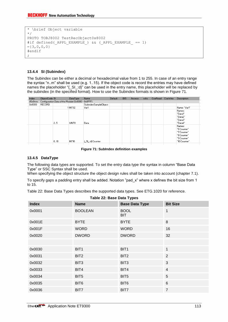
Application Note ET9300 113
* \brief Object variable
*/
PROTO TOBJ8002 TestRecObject0x8002
#if defined(_APPL_EXAMPLE_) && (_APPL_EXAMPLE_ == 1)
={3,0,0,0}
#endif
;
13.4.4 SI (Subindex)
The Subindex can be either a decimal or hexadecimal value from 1 to 255. In case of an entry range the syntax “n..m” shall be used (e.g. 1..15). If the object code is record the entries may have defined names the placeholder “{_SI_:d}” can be used in the entry name, this placeholder will be replaced by the subindex (in the specified format). How to use the Subindex formats is shown in Figure 71.
Figure 71: SubIndex definition examples
13.4.5 DataType
The following data types are supported. To set the entry data type the syntax in column “Base Data Type” or SSC Syntax shall be used. When specifying the object structure the object design rules shall be taken into account (chapter 7.1).
To specify gaps a padding entry shall be added. Notation ”pad_x” where x defines the bit size from 1 to 15.
Table 22: Base Data Types describes the supported data types. See ETG.1020 for reference.
Table 22: Base Data Types
Index Name Base Data Type Bit Size
0x0001 BOOLEAN BOOL BIT
1
0x001E BYTE BYTE 8
0x001F WORD WORD 16
0x0020 DWORD DWORD 32
0x0030 BIT1 BIT1 1
0x0031 BIT2 BIT2 2
0x0032 BIT3 BIT3 3
0x0033 BIT4 BIT4 4
0x0034 BIT5 BIT5 5
0x0035 BIT6 BIT6 6
0x0036 BIT7 BIT7 7
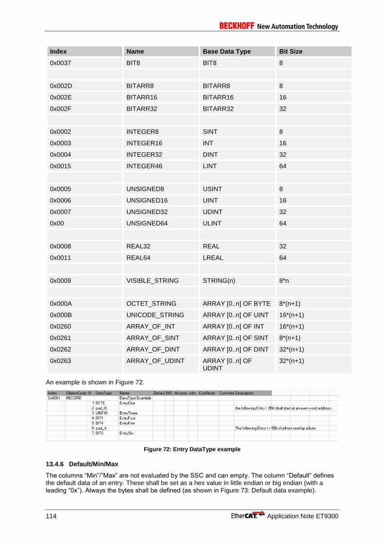
114 Application Note ET9300
Index Name Base Data Type Bit Size
0x0037 BIT8 BIT8 8
0x002D BITARR8 BITARR8 8
0x002E BITARR16 BITARR16 16
0x002F BITARR32 BITARR32 32
0x0002 INTEGER8 SINT 8
0x0003 INTEGER16 INT 16
0x0004 INTEGER32 DINT 32
0x0015 INTEGER46 LINT 64
0x0005 UNSIGNED8 USINT 8
0x0006 UNSIGNED16 UINT 16
0x0007 UNSIGNED32 UDINT 32
0x00 UNSIGNED64 ULINT 64
0x0008 REAL32 REAL 32
0x0011 REAL64 LREAL 64
0x0009 VISIBLE_STRING STRING(n) 8*n
0x000A OCTET_STRING ARRAY [0..n] OF BYTE 8*(n+1)
0x000B UNICODE_STRING ARRAY [0..n] OF UINT 16*(n+1)
0x0260 ARRAY_OF_INT ARRAY [0..n] OF INT 16*(n+1)
0x0261 ARRAY_OF_SINT ARRAY [0..n] OF SINT 8*(n+1)
0x0262 ARRAY_OF_DINT ARRAY [0..n] OF DINT 32*(n+1)
0x0263 ARRAY_OF_UDINT ARRAY [0..n] OF UDINT
32*(n+1)
An example is shown in Figure 72.
Figure 72: Entry DataType example
13.4.6 Default/Min/Max
The columns “Min”/”Max” are not evaluated by the SSC and can empty. The column “Default” defines the default data of an entry. These shall be set as a hex value in little endian or big endian (with a leading “0x”). Always the bytes shall be defined (as shown in Figure 73: Default data example).

Application Note ET9300 115
Figure 73: Default data example
13.4.7 M/O/C, B/S and rx/tx
The column “M/O/C” defines if an entry is mandatory optional or conditional. This value is only set in the ESI file and has no influence to the slave application. The column “B/S” specifies if an entry is a backup or setting object. The column “rx/tx” specifies if an entry is rx or tx PDO map able.
13.4.8 Access
Defines the access rights via CoE. The access (read, write, readwrite) can be identical in PreOp, SafeOp, Op. Or they can be different in some states. Example: A configuration value may be readable and writeable in PreOp, but must not be changed any more in Op. the allowed values are listed in Table 23: Entry access rights.
Table 23: Entry access rights
The state-dependent access rights shall be separated by a comma (,).
e.g. an entry shall readonly in SafeOP and OP and writeable in PreOP to access is “ro , wr_preop”.
13.4.9 CoeRead/CoeWrite
In case that CoE read and write requests shall be handled by the application a function name can be added to these columns (Figure 74: CoeRead/CoeWrite example). The parser will create the corresponding declaration (in the xxxObjects.h) and (in case that the application c file does not exist) the dummy function body in the application c file (Figure 75).
Figure 74: CoeRead/CoeWrite example
Syntax Description
RO Read-only in all states
WO Write-only in all states
RW Readable and writable in all states
rd_preop Readonly in Preop
rd_preop_safeop Read-only in PreOP and SafeOP
rd _safeop Read-only in SafeOP
rd_ safeop_op Read-only in SafeOP and OP
rd _op Read-only in OP
wr_preop Write only in PreOP
wr _preop_safeop Write only in PreOP and SafeOP
wr _safeop Write only in SafeOP
wr _Safeop_op Write only in SafeOP and OP
wr _op Write only in OP

116 Application Note ET9300
Figure 75: CoeRead/CoeWrite example function body
13.5 ENUM
Enums shall be defined in the index range 0x800 to 0xFFF (see also ETG.1000-6). The used name and data type shall be “DTXXXXENYY”. XXXX is the index of the enumeration and YY the used bit size.
Example
Table 24 shows an Enum definition example.
Table 24: Enum definition
Table 25 shows an example for an entry using the above defined Enum.
Table 25: Enum usage
//Index ObjectCode SI DataType M/O/C Access Default Name
0x0800 DT0800EN03
1 1 Signed
2 2 Unsigned
//Index ObjectCode SI DataType M/O/C Access
Default Name
0x8nn0 RECORD
0x01 Pad_16
0x11 DT0800EN03 M RO 2 Presentation

Application Note ET9300 117
14 EEPROM Handling
To identify an EtherCAT slave and to provide parameter (e.g. process data, supported mailbox protocols) every EtherCAT slave has to have a SII (Slave Information Interface). Usually this information is stored in an EEPROM which is connected via an I2C to the ESC. Depending on the used ESC (see ESC datasheet) it is also possible to emulate the EEPROM, which means the data is stored in the application memory and is handled by the slave application.
14.1 EEPROM Emulation
Since SSC version 5.01 EEPROM Emulation is supported and can be controlled by the defines listed in Table 26: EEPROM Emulation Defines.
Table 26: EEPROM Emulation Defines
The EEPROM emulation can be either implemented by application callback functions or by a static EEPROM data array.
Callback functions : Read/Write and reload function are described in chapter 6.2.1.
Static EEPROM data : The EEPROM content is stored in an static array, and accessed by the global pointer “pEEPROM” (defined in ecatappl.h.) and need to be initialized during startup. On an EEPROM reload command the function “HW_EepromReload” is called which shall update the Station Alias and Enhanced link detection in the EEPROM array (see SII Specification for the corresponding offsets).
In case that register 0x502 bit6 is set to 1 (8 Byte EEPROM access) the full EEPROM emulation is enabled and the reload commands are not required (reload commands are handled similar to EEPROM read).
Generating EEPROM content is required if the slave application has changed after the slave file generation with the SSC Tool or if the basic SSC is used for the slave development. Therefore an additional “EEPROM Programming” tool is provided (see chapter 14.2).
14.2 EEPROM Programming
Where a physical EEPROM is available or the EEPROM is emulated the EEPROM content needs to be generated. This can be done in multiple ways, e.g. with TwinCAT (see [3] ) or by the EEPROM programming tool (Figure 76: EEPROM Programming Tool) which is described in this chapter.
Define Description
ESC_EEPROM_EMULATION If set to 1, the EEPROM emulation is enabled and EEPROM commands are handled by the SSC.
CREATE_EEPROM_CONTENT Only available in the SSC Tool. If set to 1, then a header file including the EEPROM data according to the slave configuration will be created during the slave file generation process (see chapter 12.3 Create Files).
ESC_EEPROM_SIZE Available EEPROM buffer size in Bytes.
EEPROM_READ_SIZE Number of Bytes the ESC can handle on a single read access. See ESC datasheet for further details. ET1100/ET1200 : 8Byte
EEPROM_WRITE_SIZE Number of Bytes the ESC can handle on a single write access. This value is always 2.
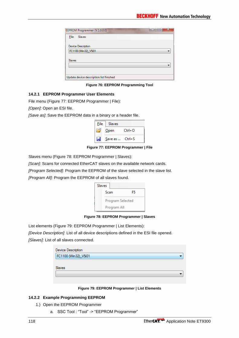
118 Application Note ET9300
Figure 76: EEPROM Programming Tool
14.2.1 EEPROM Programmer User Elements
File menu (Figure 77: EEPROM Programmer | File):
[Open]: Open an ESI file.
[Save as]: Save the EEPROM data in a binary or a header file.
Figure 77: EEPROM Programmer | File
Slaves menu (Figure 78: EEPROM Programmer | Slaves):
[Scan]: Scans for connected EtherCAT slaves on the available network cards.
[Program Selected]: Program the EEPROM of the slave selected in the slave list.
[Program All]: Program the EEPROM of all slaves found.
Figure 78: EEPROM Programmer | Slaves
List elements (Figure 79: EEPROM Programmer | List Elements):
[Device Description]: List of all device descriptions defined in the ESI file opened.
[Slaves]: List of all slaves connected.
Figure 79: EEPROM Programmer | List Elements
14.2.2 Example Programming EEPROM
1.) Open the EEPROM Programmer
a. SSC Tool : “Tool” -> “EEPROM Programmer”

Application Note ET9300 119
b. Start Menu -> Programs -> EtherCAT Slave Stack Code Tool -> EEPROM Programmer
2.) In case that the programmer is not started from the SSC Tool an ESI has to be selected (“File”-> “Open”)
3.) Scan for connected EtherCAT slaves (“F5” or “Slaves” -> “Scan”)
4.) Program
a. Program only a single EEPROM (of the selected slave), “Slaves”-> “”Program Selected”
b. Program all EEPROMs, “Slaves” -> “Program All”

120 Application Note ET9300
15 Bootloader
The SSC is prepared to be used as the base code for a Bootloader implementation. The basic bootloader features are the Bootstate and firmware download. Both features are already fully provided by the SSC and can be enabled by the following defines:
- BOOTSTRAPMODE_SUPPORTED
- FOE_SUPPORTED
The following functions are intent to be used in the firmware download process:
BL_Start(): Called in the state transition from INIT to BOOT
BL_StartDownload(): Called on a write request in case that the file name starts with "ECATFW__" (the file name is specified in aFirmwareDownloadHeader (foeappl.c)
BL_Data(): Called on every data fragment
The firmware update itself (e.g. writing the flash and reset the Controller) can either be done during the FoE file download or on the transition from BOOT to INIT. Which mechanism is implement is up to the slave vendor.
For further information about the recommend slave behavior during a state transition see the ETG.5003.2.

Application Note ET9300 121
16 Process Data
The process data is handled by three functions:
PDO_OutputMapping()
ECAT_Application()
PDO_InputMapping()
The function are called based on the configured sync mode (see 9 Synchronization).
Example for process data output mapping (Figure 80):
An example for input mapping is shown in Figure 81
Figure 80: Output mapping example

122 Application Note ET9300
16.1 Process data size
Function APPL_GenerateMapping() calculates the size of Output and Input Process Data, which can vary according to the PDO mapping. It is called by AL_ControlInd() during the PREOP_2_SAFEOP transition, and in case of error it returns AL Status Codes 0x24 “Invalid Input Mapping” and 0x25 “Invalid Output Mapping” (an error is returned if the function does not manage to get a pointer to one of the 0x16yz and 0x1Ayz expected by the 0x1C12 and 0x1C13, respectively).
This function has to be implemented by users, yet examples reported in ___appl.c files of SSC represent a general algorithm.
The following example shows the calculation for RxPDOs (Figure 82):
1. Object 0x1C12 “RxPDO Assign” is parsed
2. Each entry of 0x1C12 corresponds to a “RxPDO Mapping” Object 0x16yz
3. The corresponding Object 0x16yz “RxPDO Mapping” is parsed
4. Each entry of 0x16yz corresponds to a mapped output entry
5. The size of all mapped output entries are added in order to obtain nPdOutputSize
Figure 81: Input mapping example
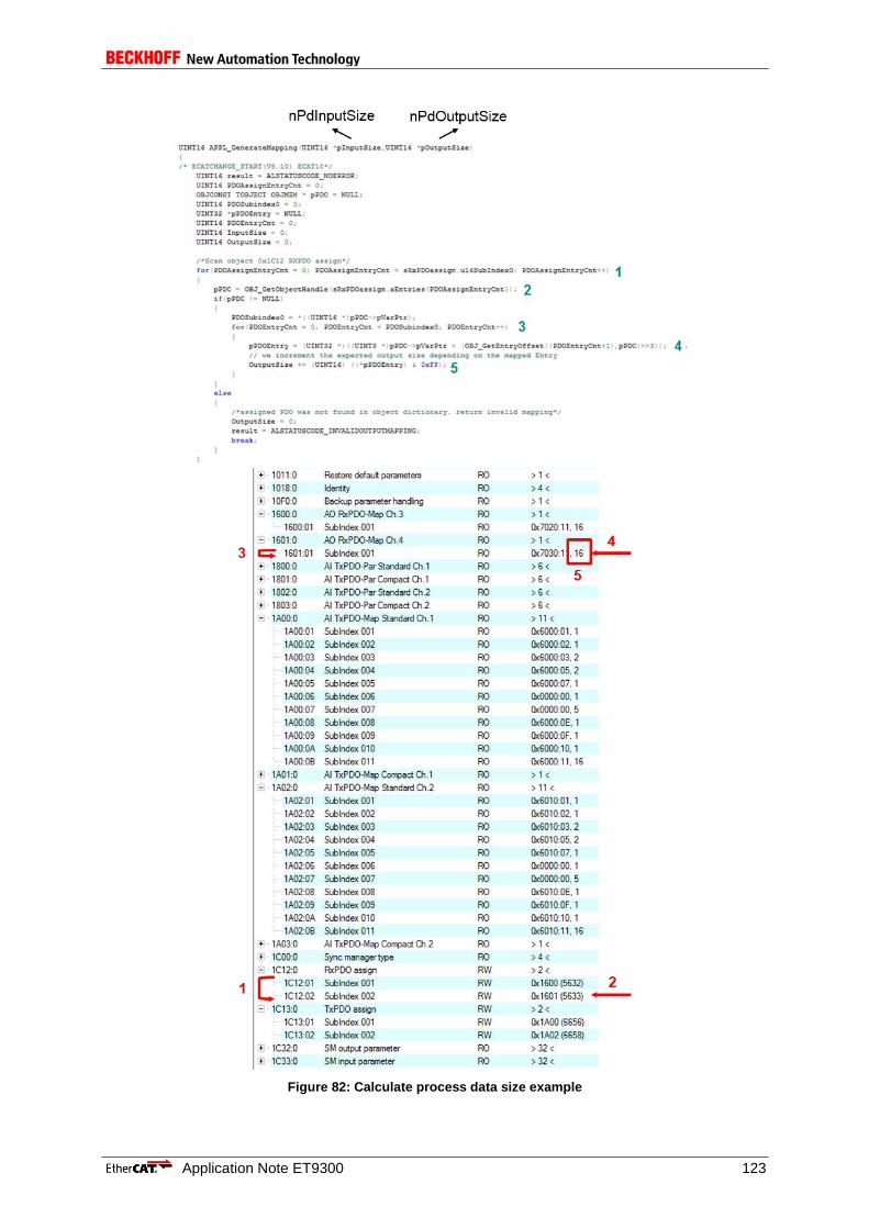
Application Note ET9300 123
Figure 82: Calculate process data size example
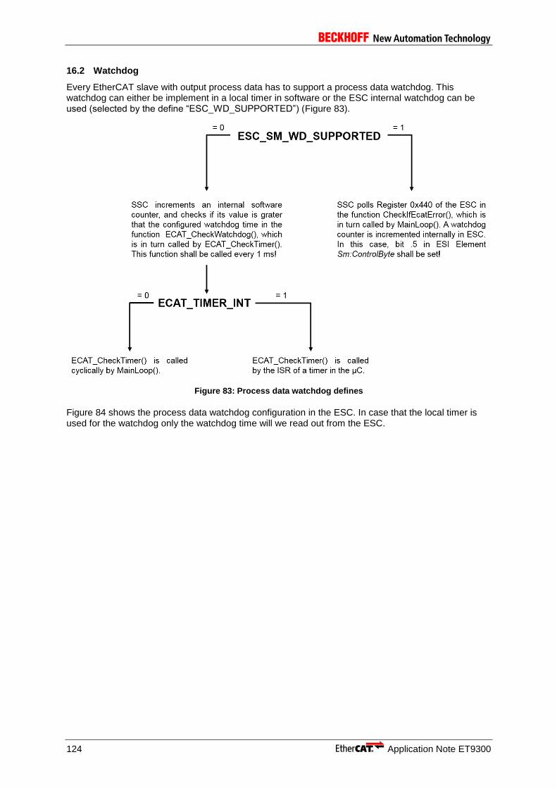
124 Application Note ET9300
16.2 Watchdog
Every EtherCAT slave with output process data has to support a process data watchdog. This watchdog can either be implement in a local timer in software or the ESC internal watchdog can be used (selected by the define “ESC_WD_SUPPORTED”) (Figure 83).
Figure 83: Process data watchdog defines
Figure 84 shows the process data watchdog configuration in the ESC. In case that the local timer is used for the watchdog only the watchdog time will we read out from the ESC.
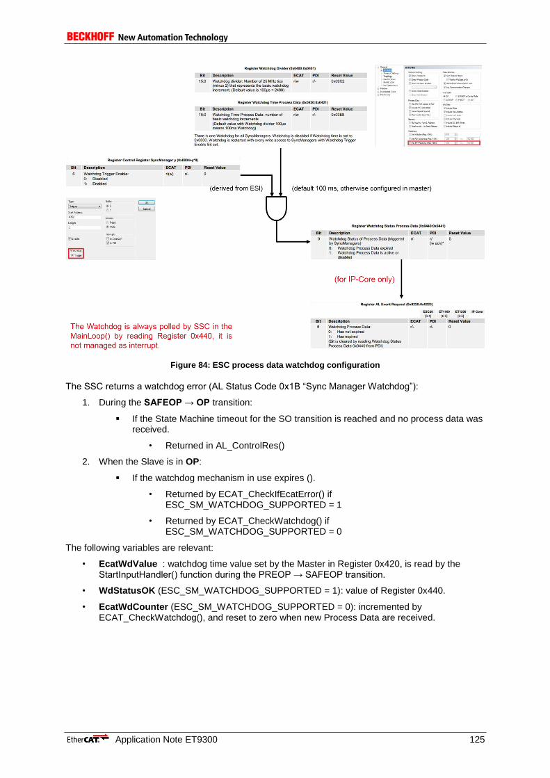
Application Note ET9300 125
Figure 84: ESC process data watchdog configuration
The SSC returns a watchdog error (AL Status Code 0x1B “Sync Manager Watchdog”):
1. During the SAFEOP → OP transition:
If the State Machine timeout for the SO transition is reached and no process data was received.
• Returned in AL_ControlRes()
2. When the Slave is in OP:
If the watchdog mechanism in use expires ().
• Returned by ECAT_CheckIfEcatError() if ESC_SM_WATCHDOG_SUPPORTED = 1
• Returned by ECAT_CheckWatchdog() if ESC_SM_WATCHDOG_SUPPORTED = 0
The following variables are relevant:
• EcatWdValue : watchdog time value set by the Master in Register 0x420, is read by the StartInputHandler() function during the PREOP → SAFEOP transition.
• WdStatusOK (ESC_SM_WATCHDOG_SUPPORTED = 1): value of Register 0x440.
• EcatWdCounter (ESC_SM_WATCHDOG_SUPPORTED = 0): incremented by ECAT_CheckWatchdog(), and reset to zero when new Process Data are received.

126 Application Note ET9300
17 EtherCAT State Machine
In the EtherCAT state machine 4 mandatory and one optional state is defined. The optional state is the boot state which is indent to be used for firmware updates (see 14.2.2).The State Machine is managed via the AL_ControlInd() and AL_ControlRes() functions, both defined in ecatslv.c file.
Figure 85 displays the 4 mandatory states and called functions for the transitions.
In Figure 86 the state machine progress is shown.
MBX_StartMailboxHandler()
MBX_StopMailboxHandler()
StartInputHandler()
StopInputHandler()
StartOutputHandler()
StopOutputHandler()
Figure 85: EtherCAT state

Application Note ET9300 127
Figure 86: ESM progress
MBX_StartMailboxHandler()
Check mailbox SyncManager (SM0 and SM1) settings
Activate mailbox SyncManager HW_EnableSyncManChannel()
Set global variable: bMbxRunning
Call Application Interface function: APPL_StartMailboxHandler()
MBX_StopMailboxHandler()
Deactivate mailbox SyncManager HW_DisableSyncManChannel()
Free mailbox Queue buffer
Clear global variable: bMbxRunning
Call Application Interface function: APPL_StopMailboxHandler()
StartInputHandler()
Check process data SyncManger settings (SM2 and SM3)

128 Application Note ET9300
Check distributed clocks settings (if enabled)
Setup process data watchdog (if enabled)
Activate output and input process data SyncManger HW_EnableSyncManChannel()
Set AL Event Mask (register 0x204:0x207)
Set global variable: bEcatInputUpdateRunning
Call Application Interface function: APPL_StartInputHandler()
StopInputHandler()
Deactivate input and output process data SyncManger HW_DisableSyncManChannel()
Reset AL Event Mask (register 0x204:0x207)
Clear global variable: bEcatInputUpdateRunning
Call Application Interface function: APPL_StopInputHandler()
StartOutputHandler()
Set global variable: bEcatOutputUpdateRunning
SM/DC Timing
Call Application Interface function: APPL_StartOutputHandler()
StopOutputHandler()
Clear global variable: bEcatOutputUpdateRunning
Call Application Interface function: APPL_StopOutputHandler()
17.1 Transition Examples
Examples for an accepted and rejected transition are shown in Figure 87 and Figure 88.
The general sequence is:
1. The master writes a new requested state (e.g. 0x04 = SafeOP) into 0x0120 “AL Control” register, then starts cyclically polling 0x0130 “AL Status” register
2. The SSC, which cyclically polls 0x0220 “AL Event Request” register, detects the new state transition request
3. The SSC calls the general purpose handler function for the requested transition, which in turn calls the corresponding application API (in the example StartInputHandler() and APPL_StartInputHandler(), respectively)
4. According to the calculation results of these functions, the SSC confirms or refuses the requested state transition by writing the new current state into 0x0130 “AL Status” register (and, in case of refusal, the corresponding error code into 0x0134 “AL Status Code” register)
5. The master, which is polling 0x0130 “AL Status” register, detects the transition result

Application Note ET9300 129
Figure 87: Accepted ESM example

130 Application Note ET9300
Figure 88: Rejected ESM example
17.2 Sync Manager
The Sync Managers (SM) are used to exchange the process data and mailbox data between the slave and master application. The assignment is follows:
SM0 : mailbox out (Master to Slave)
SM1: mailbox in (Slave to Master)
SM2: process data out (Master to Slave)
SM3: process data out (Slave to Master)
If no mailbox is supported SM0 and SM1 are used for process data exchange and if one of the process data directions is not used the corresponding Sync Manager is disabled. In Table 27 the corresponding registers are listed.
Table 27: Sync Manager Registers
SM0 SM1 SM2 SM3 Description
0x800 0x808 0x810 0x818 Physical Start Address
0x802 0x80A 0x812 0x81A Length
0x804 0x80C 0x814 0x81C Control Register
0x805 0x80D 0x814 0x81D Status Register
0x806 0x80E 0x816 0x81E Activate

Application Note ET9300 131
SM0 SM1 SM2 SM3 Description
0x807 0x80F 0x817 0x81F PDI Control
Usually a SyncManager which is enabled by the Master is also activated by the Slave, and vice-versa a SyncManager which is disabled by the Master is also deactivated by the Slave.
Disabling a SyncManager on Slave side without a corresponding deactivation by the Master happens only as error reaction mechanism, when the Slave spontaneously performs a backward transition due to internal reasons
SyncManagers are checked by 2 functions, both called by AL_ControlInd() during a state transition:
CheckSmSettings() checks the basic SyncManager settings like Address, Length, Flags (all SMs) In case of error, it returns the AL Status Codes: 0x17 “Invalid sync manager configuration” (Start Address and Length not compatible with µC architecture) 0x16 “Invalid mailbox configuration” or 0x15 “Invalid mailbox configuration (bootstrap)” (Mailbox SM settings) 0x1D “Invalid Output Configuration” or 0x1E “Invalid Input Configuration” (Process Data SM settings). This function checks also if the maximum physical size of the ESC DPRAM is exceeded. In case of error AL Status Code 0x14 “No valid firmware” is returned.
StartInputHandler() checks if the SyncManagers overlap (only Process Data SMs). In case of error, it returns AL Status Codes: 0x1D “Invalid Output Configuration” or 0x1E “Invalid Input Configuration”.
Check is performed by comparing settings sent by the Master via Init Commands with the software constants in the stack (Figure 89).
Figure 89: Sync Manager settings in the SSC Tool
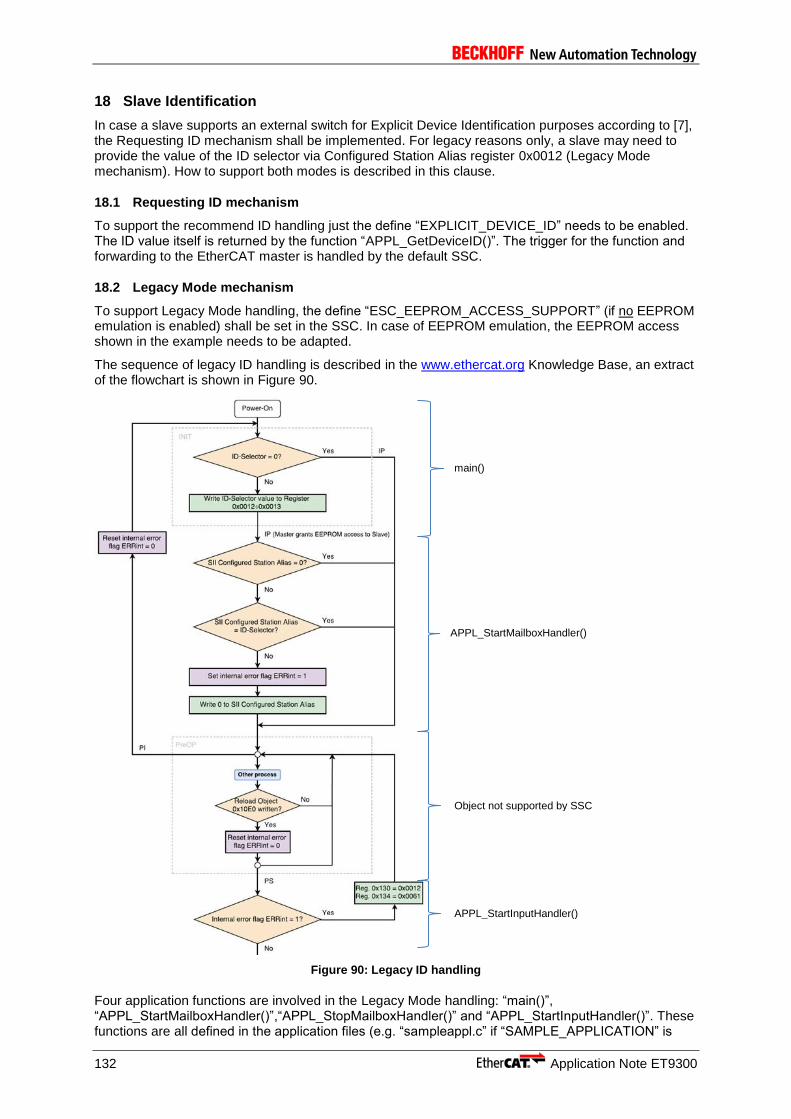
132 Application Note ET9300
18 Slave Identification
In case a slave supports an external switch for Explicit Device Identification purposes according to [7], the Requesting ID mechanism shall be implemented. For legacy reasons only, a slave may need to provide the value of the ID selector via Configured Station Alias register 0x0012 (Legacy Mode mechanism). How to support both modes is described in this clause.
18.1 Requesting ID mechanism
To support the recommend ID handling just the define “EXPLICIT_DEVICE_ID” needs to be enabled. The ID value itself is returned by the function “APPL_GetDeviceID()”. The trigger for the function and forwarding to the EtherCAT master is handled by the default SSC.
18.2 Legacy Mode mechanism
To support Legacy Mode handling, the define “ESC_EEPROM_ACCESS_SUPPORT” (if no EEPROM emulation is enabled) shall be set in the SSC. In case of EEPROM emulation, the EEPROM access shown in the example needs to be adapted.
The sequence of legacy ID handling is described in the www.ethercat.org Knowledge Base, an extract of the flowchart is shown in Figure 90.
Figure 90: Legacy ID handling
Four application functions are involved in the Legacy Mode handling: “main()”, “APPL_StartMailboxHandler()”,“APPL_StopMailboxHandler()” and “APPL_StartInputHandler()”. These functions are all defined in the application files (e.g. “sampleappl.c” if “SAMPLE_APPLICATION” is
APPL_StartMailboxHandler()
main()
Object not supported by SSC
APPL_StartInputHandler()

Application Note ET9300 133
enabled).Two additional local variables are defined UINT16 DipswitchIdValue (to store the ID value) and BOOL idError (error indication if the ID values does not match).
main():
…
MainInit();
DipswitchIdValue = 0x30; /*latching the Dipswitch shall only be done
on power up*/
if(DipswitchIdValue != 0)
{
/*Write the ID value to register 0x12 (Configured Station
Alias)*/
HW_EscWriteWord(DipswitchIdValue,0x12);
}
bRunApplication = TRUE;
do
{
MainLoop();
…
APPL_StartMailboxHandler:
UINT16 APPL_StartMailboxHandler(void)
{
UINT16 SiiIDValue = 0;
ESC_EepromAccess(0x4,1,&SiiIDValue,ESC_RD);
if((SiiIDValue != 0) && (SiiIDValue != DipswitchIdValue))
{
/*reset SII ID value in case of not matching ID values*/
SiiIDValue = 0;
ESC_EepromAccess(0x4,1,&SiiIDValue,ESC_WR);
idError = TRUE;
}
else
{
idError = FALSE;
}
return ALSTATUSCODE_NOERROR;
}
APPL_StopMailboxHandler:
UINT16 APPL_StopMailboxHandler(void)
{
idError = FALSE; /*clear the error indication on PreOP-Init
transition*/
return ALSTATUSCODE_NOERROR;
}
APPL_StartInputHandler:
UINT16 APPL_StartInputHandler(UINT16 *pIntMask)
{
if(idError == TRUE)
{
return 0x61; /*AL Status Error Code ID values not match*/
}
return ALSTATUSCODE_NOERROR;
}

134 Application Note ET9300
Appendix
Support and Service
Beckhoff and their partners around the world offer comprehensive support and service, making available fast and competent assistance with all questions related to Beckhoff products and system solutions.
Beckhoff’s branch offices and representatives
Please contact your Beckhoff branch office or representative for local support and service on Beckhoff products! The addresses of Beckhoff's branch offices and representatives round the world can be found on her internet pages: http://www.beckhoff.com You will also find further documentation for Beckhoff components there.
Beckhoff Headquarters
Beckhoff Automation GmbH & Co. KG Hülshorstweg 20 33415 Verl Germany phone: + 49 (0) 5246/963-0 fax: + 49 (0) 5246/963-198 e-mail: [email protected] web: www.beckhoff.com
Beckhoff Support
Support offers you comprehensive technical assistance, helping you not only with the application of individual Beckhoff products, but also with other, wide-ranging services: world-wide support design, programming and commissioning of complex automation systems and extensive training program for Beckhoff system components hotline: + 49 (0) 5246/963-157 fax: + 49 (0) 5246/963-9157 e-mail: [email protected]
Beckhoff Service
The Beckhoff Service Center supports you in all matters of after-sales service: on-site service repair service spare parts service hotline service hotline: + 49 (0) 5246/963-460 fax: + 49 (0) 5246/963-479 e-mail: [email protected]
EtherCAT Technology Group (ETG) Headquarters
Phone: +49 (911) 540 5620 Fax: +49 (911) 540 5629 Email: [email protected] Internet: www.ethercat.org