ethercat slave implementation guide · nomenclature: etg-number etg.2200 created by: ... is...
TRANSCRIPT
Slave Implementation Guide
Document: ETG.2200 V2.1.0
Section I EtherCAT Slave Introduction and Implementation Procedure
Section II EtherCAT Development Components
Nomenclature:
ETG-Number ETG.2200
Created by: ETG
Contact: [email protected]
Date: 13.01.2014
LEGAL NOTICE
LEGAL NOTICE
Trademarks and Patents EtherCAT® is a registered trademark and patented technology, licensed by Beckhoff Automation GmbH, Germany. Other designations used in this publication may be trademarks whose use by third parties for their own purposes could violate the rights of the owners.
Disclaimer
The documentation has been prepared with care. The technology described is, however, constantly under development. For that reason the documentation is not in every case checked for consistency with performance data, standards or other characteristics. In the event that it contains technical or editorial errors, we retain the right to make alterations at any time and without warning. No claims for the modification of products that have already been supplied may be made on the basis of the data, diagrams and descriptions in this documentation.
Copyright
© EtherCAT Technology Group 2014.
The reproduction, distribution and utilization of this document as well as the communication of its contents to others without express authorization is prohibited. Offenders will be held liable for the payment of damages. All rights reserved in the event of the grant of a patent, utility model or design.
ETG.2200 EtherCAT Slave Implementation Guide 2
DOCUMENT HISTORY
DOCUMENT HISTORY
Version Comment 1.0.0 Official Release 1.1.0 Document revised
• Editorial Changes • ESC Variants updated • More Implementation Products added • New Documentation Links
1.1.1 Editorial Changes 1.1.2 Use of Marking Rules and Indicator Specification added 1.1.3 Editorial Changes 1.1.4 Editorial Changes 1.1.5 Editorial Changes
• Conformance Test Policy added • Vendor ID Policy added • Minor changes in Step by Step Implementation
1.1.6 Editorial Changes 2.0.0 Document revised
• New document structure • Enhanced General Procedure - Step by Step • Major content enhancements
2.0.1 Editorial Changes • Policies added • Download links updated/fixed • Minor content enhancements
2.0.3 Editorial Changes 2.1.0 Contact email address is [email protected]
ETG.2200 EtherCAT Slave Implementation Guide 3
DOCUMENT ORGANIZATION
DOCUMENT ORGANIZATION
This document describes how to accomplish a successful EtherCAT® slave implementation from a generic and a practical point of view. It answers the following questions:
1. How is the EtherCAT slave architecture? 2. What steps have to be done to implement an EtherCAT slave? 3. Which documents are available for a successful device implementation? 4. What kinds of EtherCAT development components are available? What are the differences? 5. Is EtherCAT training available? 6. Is technical support available? 7. Why to attend a Plug Fest? 8. How to obtain conformance for EtherCAT devices?
There are many possibilities how an EtherCAT slave implementation can be done. However, the way it is described in this document has proofed many times to lead fast to an EtherCAT slave device implementation. The document is organized in two sections:
Section I – EtherCAT Slave Introduction and Implementation Procedure Section I deals with principal aspects of an EtherCAT slave implementation. Chapter 1 provides a brief EtherCAT technology background focusing the slave. In chapter 2 the implementation steps for a slave device are described, containing slave implementation criteria and a list of useful tools. Exemplary implementation notes are given here, too. Chapter 3 describes support which is provided by the EtherCAT Technology Group.
Section II – Development Components
Section II contains device specific descriptions for further implementation aspects. An overview to available evaluation boards is given in chapter 1. Following is a list of available EtherCAT Communication Modules in chapter 2, and Slave Controllers (ESCs) in chapter 3.
® EtherCAT is registered trademark and patented technology, licensed by Beckhoff Automation GmbH, Germany.
ETG.2200 EtherCAT Slave Implementation Guide 4
EtherCAT Slave Implementation Guide
Slave Implementation Guide
SECTION I – EtherCAT Slave Introduction and Implementation Procedure
Technology overview, Network Architecture and Functionality, Slave Implementation Procedure, Exemplary Implementation, Support and Training, EtherCAT Technology Group

CONTENTS
CONTENTS
Document: ETG.2200 V2.1.0 .......................................................................................................1
SECTION I – EtherCAT Slave Introduction and Implementation Procedure ...........................................5
1 Introduction ...................................................................................................................................11
1.1 Documents for Detailed Information and Further Reading ......................................11
1.2 EtherCAT System Architecture ................................................................................13
1.2.1 Configuration Tool ....................................................................................13
1.2.2 Master System .........................................................................................13
1.2.3 Slave Device ...........................................................................................14
1.3 EtherCAT Technology Overview .............................................................................17
1.3.1 Frame Processing Order ..........................................................................17
1.3.2 EEPROM EtherCAT Slave Configuration ................................................18
1.3.3 Fieldbus Memory Management Unit ........................................................18
1.3.4 SyncManager ...........................................................................................19
1.3.5 Distributed Clocks ....................................................................................20
1.3.6 Data Structure and Communication Protocols .........................................20
1.3.7 EtherCAT State Machine ..........................................................................21
2 EtherCAT Slave Implementation ..................................................................................................23
2.1 General Procedure – Step by Step ..........................................................................23
2.2 Administrative Organization .....................................................................................24
2.2.1 Development Time ...................................................................................24
2.2.2 ETG Membership and Vendor ID .............................................................24
2.2.3 EtherCAT Conformance Test Tool License .............................................24
2.3 EtherCAT Slave Design ...........................................................................................25
2.3.1 Bus Interface to EtherCAT Network .........................................................25
2.3.2 EtherCAT Slave Controller (ESC) and PDI ..............................................25
2.3.3 EEPROM ..................................................................................................27
2.3.4 Application Controller (Host Controller, µC) .............................................27
2.3.5 Application Layer Communication Protocols ............................................27
2.3.6 Device Profiles .........................................................................................29
2.3.7 Synchronization with other Devices .........................................................30
2.4 Tools for EtherCAT Slave Development ..................................................................32
2.4.1 XML Editor for Generating ESI files .........................................................33
2.4.2 EtherCAT Network Configurator and Master Software ............................34
2.4.3 Monitoring Communication and Network Diagnosis using Wireshark .....35
2.4.4 EtherCAT Conformance Test Tool for Debugging ...................................36
2.5 EtherCAT Product Labels and LEDs .......................................................................37
2.6 Official Conformance Test at an ETC ......................................................................39
2.7 Technical Support Tips ............................................................................................39
3 EtherCAT Technology Group – Events and Support ...................................................................40
3.1 Basic Information about the ETG ............................................................................40
ETG.2200 EtherCAT Slave Implementation Guide I-6
CONTENTS
3.2 EtherCAT Training and Workshops from ETG Members ........................................41
3.3 Plug Fests ................................................................................................................42
3.4 Official EtherCAT Conformance Test Certificate .....................................................42
3.5 Technical Committee ...............................................................................................42
3.6 Forum .......................................................................................................................43
3.7 Knowledge Base ......................................................................................................43
3.8 Technical Support ....................................................................................................43
SECTION II – Development Components ..............................................................................................45
1 EtherCAT Slave Evaluation Boards .............................................................................................51
1.1 Beckhoff EtherCAT Evaluation Kit EL98xx ..............................................................51
1.2 EBV DBC3C40 (Mercury Code) ..............................................................................52
1.3 Hilscher NXHX 500-RE Evaluation Board ...............................................................53
1.4 Texas Instruments AM3359 Industrial Communications Engine (ICE) ...................54
1.5 Texas Instruments AM3359 Industrial Development Kit (IDK) ................................55
2 EtherCAT Slave Communication Modules ...................................................................................56
2.1 EtherCAT Communication Modules Overview ........................................................56
2.2 Beckhoff FB11xx ......................................................................................................57
2.3 Hilscher comX ..........................................................................................................58
3 EtherCAT Slave Controller (ESC) Variants ..................................................................................59
4 Missing your device? ....................................................................................................................60
ETG.2200 EtherCAT Slave Implementation Guide I-7
TABLES
TABLES
Table 1: EtherCAT Information, Standards and References ................................................................ 11
Table 2: EtherCAT State Machine Description ...................................................................................... 21
Table 3: EtherCAT State Machine Transitions ...................................................................................... 22
Table 4: Components to develop/configure for EtherCAT Devices ....................................................... 24
Table 5: DPRAM Size Calculation Example .......................................................................................... 26
Table 6: FMMU Configuration ............................................................................................................... 26
Table 7: The Modular Device Profile Object Dictionary ........................................................................ 29
Table 8: Tools ........................................................................................................................................ 32
Table 9: RUN and ERR LED Indications ............................................................................................... 37
Table 10: Port and L/A LED Label Requirements ................................................................................. 37
Table 11: ETG Training ......................................................................................................................... 41
Table 12: EtherCAT Workshops from Vendors ..................................................................................... 41
Table 13: EL9800 - Scope of Delivery ................................................................................................... 51
Table 14: EtherCAT Communication Modules ...................................................................................... 56
Table 15: FB11xx Options ..................................................................................................................... 57
Table 16: EtherCAT Slave Controller Overview .................................................................................... 59
ETG.2200 EtherCAT Slave Implementation Guide I-8
FIGURES
FIGURES
Figure 1: EtherCAT Network Architecture ............................................................................................. 13
Figure 2: EtherCAT Slave Architecture ................................................................................................. 14
Figure 3: FPGA Implementations of an EtherCAT Slave ...................................................................... 15
Figure 4: ESC with 4 Ports and Frame Processing Order .................................................................... 17
Figure 5: EtherCAT Frame Structure .................................................................................................... 17
Figure 6: EEPROM Table of Register Values ....................................................................................... 18
Figure 7: Mapping Example of Process Data with FMMU .................................................................... 18
Figure 8: SyncManager in Mailbox Mode .............................................................................................. 19
Figure 9: SyncManager 3-Buffer-Mode ................................................................................................. 19
Figure 10: EtherCAT Slave State Machine ........................................................................................... 21
Figure 11: EtherCAT Network Initialization ........................................................................................... 22
Figure 12: EtherCAT Device Development Procedure ......................................................................... 23
Figure 13: ESC Structure for CAN application profile Applications ....................................................... 28
Figure 14: Slave Stack Code Overview ................................................................................................. 28
Figure 15: Slave Control Stack .............................................................................................................. 29
Figure 16: MDP Schema for Modular Devices ...................................................................................... 30
Figure 17: ESI Structure (EtherCATInfo.xsd) ........................................................................................ 33
Figure 18: ESI File Generation using a Graphical Editor ...................................................................... 33
Figure 19: EtherCAT Network Configurator .......................................................................................... 34
Figure 20: TwinCAT Device Scan, Box Scan and Adapter Settings ..................................................... 34
Figure 21: Wireshark Screenshot .......................................................................................................... 35
Figure 22: Testing with the Conformance Test Tool ............................................................................. 36
Figure 23: EtherCAT Product Branding Logos ...................................................................................... 37
Figure 24: Connecting ESC and Ethernet PHY..................................................................................... 38
Figure 25: LVDS Connection ................................................................................................................. 38
Figure 26: EtherCAT Conformance Test Logos .................................................................................... 42
Figure 27: Beckhoff Evaluation Board ................................................................................................... 51
Figure 28: EBV DBC3C40 Cyclone III Dev Board ................................................................................. 52
Figure 29: Hilscher NXHX 500-RE ........................................................................................................ 53
Figure 30: AM3359 Industrial Communications Engine (ICE) ............................................................... 54
Figure 31: AM3359 Industrial Development Kit (IDK) ........................................................................... 55
Figure 32: Beckhoff FB11xx .................................................................................................................. 57
Figure 33: Hilscher comX module ......................................................................................................... 58
ETG.2200 EtherCAT Slave Implementation Guide I-9
ABBREVIATIONS
ABBREVIATIONS
µC Microcontroller, host controller, application controller AoE ADS over EtherCAT ASIC Application Specific Integrated Circuit CoE CAN application protocol over EtherCAT CPU Central Processing Unit DC Distributed Clocks DPRAM Dual Ported Random Access Memory ENI EtherCAT Network Information (Network configuration in XML format) EoE Ethernet over EtherCAT ESC EtherCAT Slave Controller ESI EtherCAT Slave Information (device description in XML format) ESM EtherCAT State Machine ETG EtherCAT Technology Group EtherCAT Ethernet for Control Automation Technology FMMU Fieldbus Memory Management Unit FoE File Access over EtherCAT FSoE Fieldbus Safety over EtherCAT FPGA Field Programmable Gate Array GPIO General Purpose I/O LED Light Emitting Diode LVDS Low Voltage Differential Signalling MII Media Independent Interface MDP Modular Device Profile NIC Network Interface Controller NVRAM Non Volatile Random Access Memory OEM Original Equipment Manufacturer PDI Process Data Interface PDO Process Data Object PIC Programmable Integrated Circuit PLC Programmable Logic Controller RMII Reduced Media Independent Interface SII Slave Information Interface SoE Servo drive over EtherCAT SPI Serial Peripheral Interface TCP/IP Transmission Control Protocol/Internet Protocol USB Universal Serial Bus XML Extended Mark-up Language
ETG.2200 EtherCAT Slave Implementation Guide I-10
Introduction
1 Introduction This chapter presents a brief overview to the EtherCAT technology. Since EtherCAT technology covers more details than presented here, a list of documents which provide deeper understanding of the technology is given first. Corresponding text passages in this guide refer to these documents. In the following subsections the basic system architecture and the system functionality of an EtherCAT network is described. Since this is a slave implementation guide, it focuses on the slave.
1.1 Documents for Detailed Information and Further Reading
It is recommended to consider the following information before proceeding to develop an EtherCAT device. Some of the information below is provided in the member area1 of the website of the EtherCAT Technology Group (ETG). ETG membership is free of charge and is required to access the wide range of EtherCAT related documents, specifications and guidelines, as well as to receive technical support from the ETG. See chapter 2.2.2 for how to become a member and to get an account.
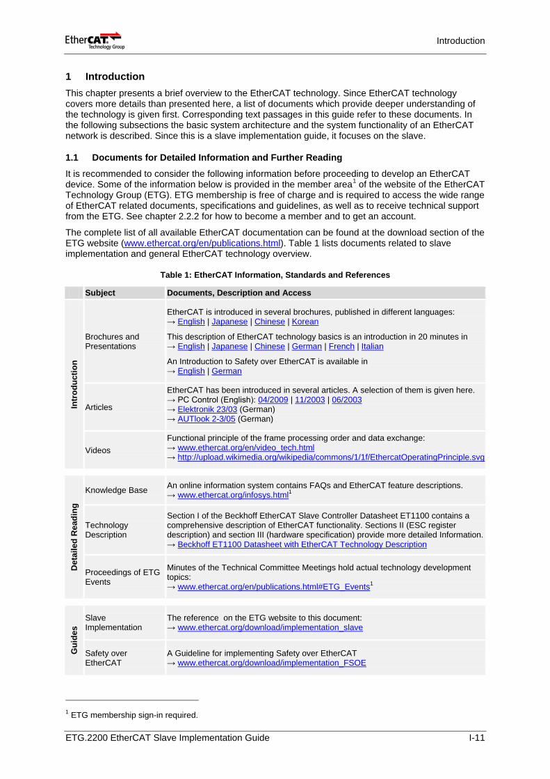
The complete list of all available EtherCAT documentation can be found at the download section of the ETG website (www.ethercat.org/en/publications.html). Table 1 lists documents related to slave implementation and general EtherCAT technology overview.
Table 1: EtherCAT Information, Standards and References
1 ETG membership sign-in required.
Subject Documents, Description and Access
Intr
oduc
tion
Brochures and Presentations
EtherCAT is introduced in several brochures, published in different languages: → English | Japanese | Chinese | Korean
This description of EtherCAT technology basics is an introduction in 20 minutes in → English | Japanese | Chinese | German | French | Italian
An Introduction to Safety over EtherCAT is available in → English | German
Articles
EtherCAT has been introduced in several articles. A selection of them is given here. → PC Control (English): 04/2009 | 11/2003 | 06/2003 → Elektronik 23/03 (German) → AUTlook 2-3/05 (German)
Videos Functional principle of the frame processing order and data exchange: → www.ethercat.org/en/video_tech.html → http://upload.wikimedia.org/wikipedia/commons/1/1f/EthercatOperatingPrinciple.svg
Det
aile
d R
eadi
ng
Knowledge Base An online information system contains FAQs and EtherCAT feature descriptions. → www.ethercat.org/infosys.html1
Technology Description
Section I of the Beckhoff EtherCAT Slave Controller Datasheet ET1100 contains a comprehensive description of EtherCAT functionality. Sections II (ESC register description) and section III (hardware specification) provide more detailed Information. → Beckhoff ET1100 Datasheet with EtherCAT Technology Description
Proceedings of ETG Events
Minutes of the Technical Committee Meetings hold actual technology development topics: → www.ethercat.org/en/publications.html#ETG_Events1
Gui
des
Slave Implementation
The reference on the ETG website to this document: → www.ethercat.org/download/implementation_slave
Safety over EtherCAT
A Guideline for implementing Safety over EtherCAT → www.ethercat.org/download/implementation_FSOE
ETG.2200 EtherCAT Slave Implementation Guide I-11
Introduction
Dev
elop
men
t Communication Slides
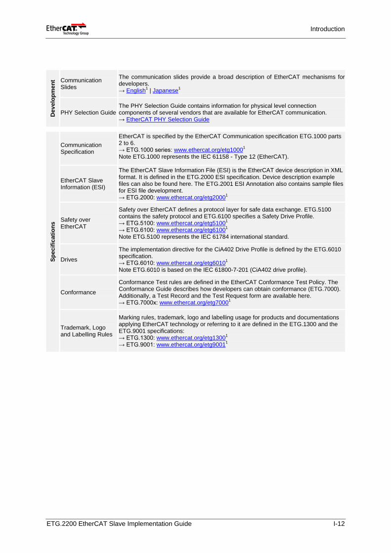
The communication slides provide a broad description of EtherCAT mechanisms for developers. → English1 | Japanese1
PHY Selection Guide The PHY Selection Guide contains information for physical level connection components of several vendors that are available for EtherCAT communication. → EtherCAT PHY Selection Guide
Spec
ifica
tions
Communication Specification
EtherCAT is specified by the EtherCAT Communication specification ETG.1000 parts 2 to 6. → ETG.1000 series: www.ethercat.org/etg10001
Note ETG.1000 represents the IEC 61158 - Type 12 (EtherCAT).
EtherCAT Slave Information (ESI)
The EtherCAT Slave Information File (ESI) is the EtherCAT device description in XML format. It is defined in the ETG.2000 ESI specification. Device description example files can also be found here. The ETG.2001 ESI Annotation also contains sample files for ESI file development. → ETG.2000: www.ethercat.org/etg20001
Safety over EtherCAT
Safety over EtherCAT defines a protocol layer for safe data exchange. ETG.5100 contains the safety protocol and ETG.6100 specifies a Safety Drive Profile. → ETG.5100: www.ethercat.org/etg51001
→ ETG.6100: www.ethercat.org/etg61001
Note ETG.5100 represents the IEC 61784 international standard.
Drives
The implementation directive for the CiA402 Drive Profile is defined by the ETG.6010 specification. → ETG.6010: www.ethercat.org/etg60101
Note ETG.6010 is based on the IEC 61800-7-201 (CiA402 drive profile).
Conformance
Conformance Test rules are defined in the EtherCAT Conformance Test Policy. The Conformance Guide describes how developers can obtain conformance (ETG.7000). Additionally, a Test Record and the Test Request form are available here. → ETG.7000x: www.ethercat.org/etg70001
Trademark, Logo and Labelling Rules
Marking rules, trademark, logo and labelling usage for products and documentations applying EtherCAT technology or referring to it are defined in the ETG.1300 and the ETG.9001 specifications: → ETG.1300: www.ethercat.org/etg13001 → ETG.9001: www.ethercat.org/etg90011
ETG.2200 EtherCAT Slave Implementation Guide I-12
Introduction
1.2 EtherCAT System Architecture
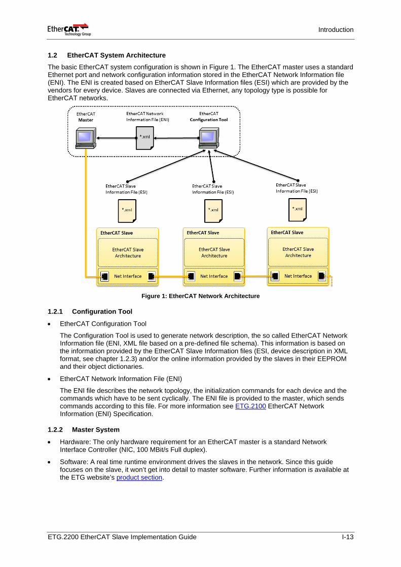
The basic EtherCAT system configuration is shown in Figure 1. The EtherCAT master uses a standard Ethernet port and network configuration information stored in the EtherCAT Network Information file (ENI). The ENI is created based on EtherCAT Slave Information files (ESI) which are provided by the vendors for every device. Slaves are connected via Ethernet, any topology type is possible for EtherCAT networks.
Figure 1: EtherCAT Network Architecture
1.2.1 Configuration Tool
• EtherCAT Configuration Tool
The Configuration Tool is used to generate network description, the so called EtherCAT Network Information file (ENI, XML file based on a pre-defined file schema). This information is based on the information provided by the EtherCAT Slave Information files (ESI, device description in XML format, see chapter 1.2.3) and/or the online information provided by the slaves in their EEPROM and their object dictionaries.
• EtherCAT Network Information File (ENI)
The ENI file describes the network topology, the initialization commands for each device and the commands which have to be sent cyclically. The ENI file is provided to the master, which sends commands according to this file. For more information see ETG.2100 EtherCAT Network Information (ENI) Specification.
1.2.2 Master System
• Hardware: The only hardware requirement for an EtherCAT master is a standard Network Interface Controller (NIC, 100 MBit/s Full duplex).
• Software: A real time runtime environment drives the slaves in the network. Since this guide focuses on the slave, it won’t get into detail to master software. Further information is available at the ETG website’s product section.
ETG.2200 EtherCAT Slave Implementation Guide I-13
Introduction
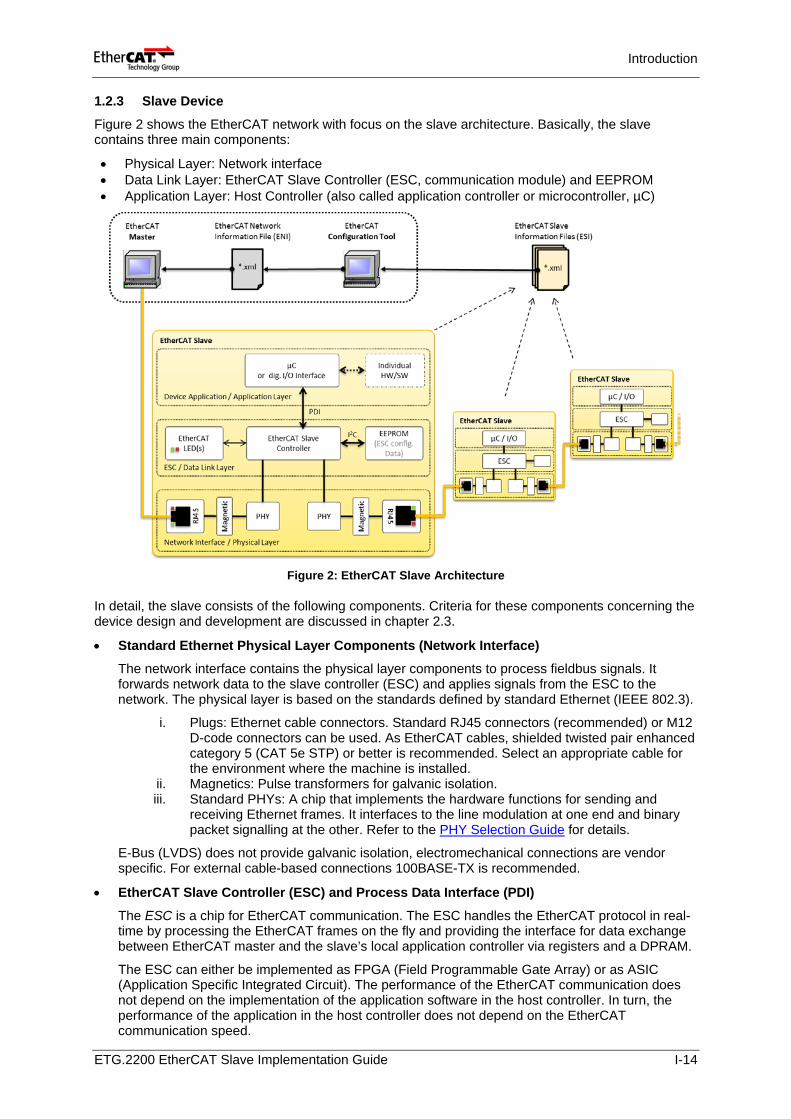
1.2.3 Slave Device
Figure 2 shows the EtherCAT network with focus on the slave architecture. Basically, the slave contains three main components:
• Physical Layer: Network interface • Data Link Layer: EtherCAT Slave Controller (ESC, communication module) and EEPROM • Application Layer: Host Controller (also called application controller or microcontroller, µC)
Figure 2: EtherCAT Slave Architecture
In detail, the slave consists of the following components. Criteria for these components concerning the device design and development are discussed in chapter 2.3.
• Standard Ethernet Physical Layer Components (Network Interface) The network interface contains the physical layer components to process fieldbus signals. It forwards network data to the slave controller (ESC) and applies signals from the ESC to the network. The physical layer is based on the standards defined by standard Ethernet (IEEE 802.3).
i. Plugs: Ethernet cable connectors. Standard RJ45 connectors (recommended) or M12 D-code connectors can be used. As EtherCAT cables, shielded twisted pair enhanced category 5 (CAT 5e STP) or better is recommended. Select an appropriate cable for the environment where the machine is installed.
ii. Magnetics: Pulse transformers for galvanic isolation. iii. Standard PHYs: A chip that implements the hardware functions for sending and
receiving Ethernet frames. It interfaces to the line modulation at one end and binary packet signalling at the other. Refer to the PHY Selection Guide for details.
E-Bus (LVDS) does not provide galvanic isolation, electromechanical connections are vendor specific. For external cable-based connections 100BASE-TX is recommended.
• EtherCAT Slave Controller (ESC) and Process Data Interface (PDI)
The ESC is a chip for EtherCAT communication. The ESC handles the EtherCAT protocol in real-time by processing the EtherCAT frames on the fly and providing the interface for data exchange between EtherCAT master and the slave’s local application controller via registers and a DPRAM.
The ESC can either be implemented as FPGA (Field Programmable Gate Array) or as ASIC (Application Specific Integrated Circuit). The performance of the EtherCAT communication does not depend on the implementation of the application software in the host controller. In turn, the performance of the application in the host controller does not depend on the EtherCAT communication speed.
ETG.2200 EtherCAT Slave Implementation Guide I-14
Introduction
The ESC processes EtherCAT frames on the fly and provides data for a local host controller or digital I/Os via the Process Data Interface (PDI). PDI availabilities depend on the ESC type (Table 16). The PDI is either:
i. Up to 32 Bit digital I/O ii. Serial Peripheral Interface (SPI) iii. 8/16-bit synchronous/asynchronous Microcontroller Interface (MCI) iv. With FPGA: specific on-board-bus (Avalon on Altera devices resp. OPB on Xilinx
devices)
Process data and parameters are exchanged via a DPRAM in the ESC. To ensure data consistency appropriate mechanisms are provided by the ESC hardware (defined by the EtherCAT protocol, e.g. SyncManager, chapter 1.3.4).
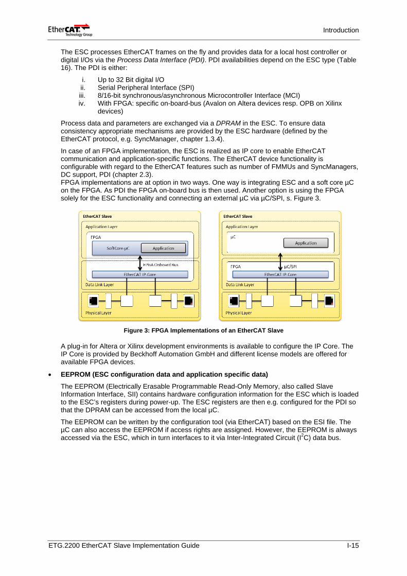
In case of an FPGA implementation, the ESC is realized as IP core to enable EtherCAT communication and application-specific functions. The EtherCAT device functionality is configurable with regard to the EtherCAT features such as number of FMMUs and SyncManagers, DC support, PDI (chapter 2.3). FPGA implementations are at option in two ways. One way is integrating ESC and a soft core µC on the FPGA. As PDI the FPGA on-board bus is then used. Another option is using the FPGA solely for the ESC functionality and connecting an external µC via µC/SPI, s. Figure 3.
Figure 3: FPGA Implementations of an EtherCAT Slave
A plug-in for Altera or Xilinx development environments is available to configure the IP Core. The IP Core is provided by Beckhoff Automation GmbH and different license models are offered for available FPGA devices.
• EEPROM (ESC configuration data and application specific data)
The EEPROM (Electrically Erasable Programmable Read-Only Memory, also called Slave Information Interface, SII) contains hardware configuration information for the ESC which is loaded to the ESC’s registers during power-up. The ESC registers are then e.g. configured for the PDI so that the DPRAM can be accessed from the local µC.
The EEPROM can be written by the configuration tool (via EtherCAT) based on the ESI file. The µC can also access the EEPROM if access rights are assigned. However, the EEPROM is always accessed via the ESC, which in turn interfaces to it via Inter-Integrated Circuit (I2C) data bus.
ETG.2200 EtherCAT Slave Implementation Guide I-15
Introduction
• Application Layer Host Controller (µC)
Application layer services, i.e. communication software and device specific software, can be implemented on a local µC. This controller then handles the following:
i. EtherCAT State Machine (ESM) in the slave device (chapter 1.3.7) ii. Process data exchange with the slave application (e.g. application and configuration
parameters, object dictionary, chapter 2.3.6) iii. Mailbox-based protocols for acyclic data exchange (CoE, EoE, FoE, chapter 1.3.6) iv. Optional TCP/IP stack if the device supports EoE
The µC-performance depends solely on the device application, not on the EtherCAT communication. In many cases an 8-bit µC / PIC is sufficient.
• EtherCAT Slave Information File (ESI)
Every EtherCAT device must be delivered with an EtherCAT Slave Information file (ESI), a device description document in XML format. Information about device functionality and settings is provided by the ESI. ESI files are used by the configuration tool to compile network information (ENI) in offline mode (e.g. process data structures, initialization commands).
Refer to the ETG.2000 EtherCAT Slave Information Specification for the description details of the ESI file. See also related description in chapter 2.4.1.
• Individual HW/SW
Eventually, additional device or vendor specific hardware or software is used to implement the device functionality, e.g. optics/optoelectronics in sensors, plugs in gateways, displays, etc. This hardware is connected to the host controller and is not understood here as part of the EtherCAT functionality.
ETG.2200 EtherCAT Slave Implementation Guide I-16
Introduction
1.3 EtherCAT Technology Overview
In this chapter, basic EtherCAT slave features and functionalities are explained in a short. Refer to referenced material in chapter 1.1 for more details.
1.3.1 Frame Processing Order
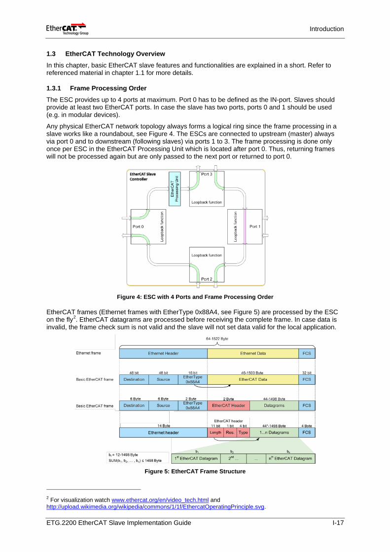
The ESC provides up to 4 ports at maximum. Port 0 has to be defined as the IN-port. Slaves should provide at least two EtherCAT ports. In case the slave has two ports, ports 0 and 1 should be used (e.g. in modular devices).
Any physical EtherCAT network topology always forms a logical ring since the frame processing in a slave works like a roundabout, see Figure 4. The ESCs are connected to upstream (master) always via port 0 and to downstream (following slaves) via ports 1 to 3. The frame processing is done only once per ESC in the EtherCAT Processing Unit which is located after port 0. Thus, returning frames will not be processed again but are only passed to the next port or returned to port 0.
Figure 4: ESC with 4 Ports and Frame Processing Order
EtherCAT frames (Ethernet frames with EtherType 0x88A4, see Figure 5) are processed by the ESC on the fly2. EtherCAT datagrams are processed before receiving the complete frame. In case data is invalid, the frame check sum is not valid and the slave will not set data valid for the local application.
Figure 5: EtherCAT Frame Structure
2 For visualization watch www.ethercat.org/en/video_tech.html and http://upload.wikimedia.org/wikipedia/commons/1/1f/EthercatOperatingPrinciple.svg.
ETG.2200 EtherCAT Slave Implementation Guide I-17
Introduction
1.3.2 EEPROM EtherCAT Slave Configuration
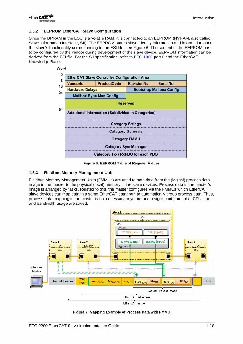
Since the DPRAM in the ESC is a volatile RAM, it is connected to an EEPROM (NVRAM, also called Slave Information Interface, SII). The EEPROM stores slave identity information and information about the slave's functionality corresponding to the ESI file, see Figure 6. The content of the EEPROM has to be configured by the vendor during development of the slave device. EEPROM information can be derived from the ESI file. For the SII specification, refer to ETG.1000-part 6 and the EtherCAT Knowledge Base.
Figure 6: EEPROM Table of Register Values
1.3.3 Fieldbus Memory Management Unit
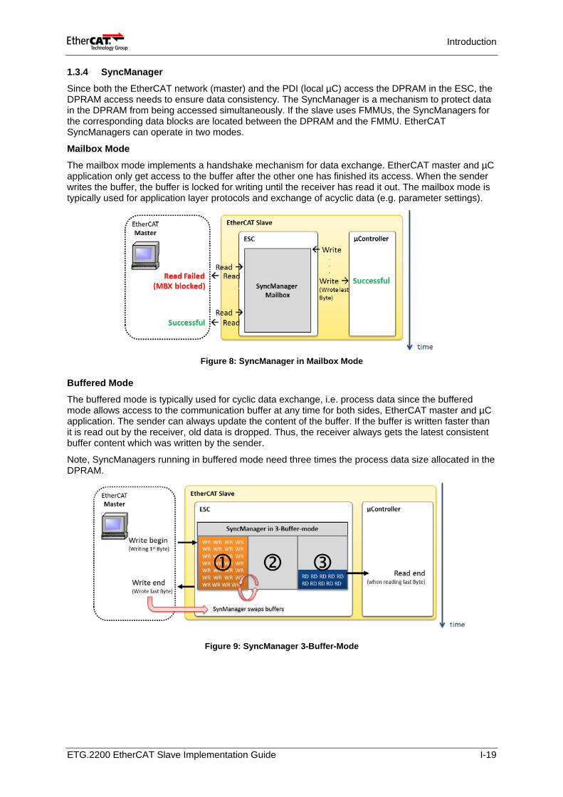
Fieldbus Memory Management Units (FMMUs) are used to map data from the (logical) process data image in the master to the physical (local) memory in the slave devices. Process data in the master’s image is arranged by tasks. Related to this, the master configures via the FMMUs which EtherCAT slave devices can map data in a same EtherCAT datagram to automatically group process data. Thus, process data mapping in the master is not necessary anymore and a significant amount of CPU time and bandwidth usage are saved.
Figure 7: Mapping Example of Process Data with FMMU
ETG.2200 EtherCAT Slave Implementation Guide I-18
Introduction
1.3.4 SyncManager
Since both the EtherCAT network (master) and the PDI (local µC) access the DPRAM in the ESC, the DPRAM access needs to ensure data consistency. The SyncManager is a mechanism to protect data in the DPRAM from being accessed simultaneously. If the slave uses FMMUs, the SyncManagers for the corresponding data blocks are located between the DPRAM and the FMMU. EtherCAT SyncManagers can operate in two modes.
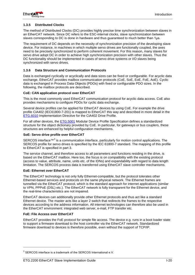
Mailbox Mode
The mailbox mode implements a handshake mechanism for data exchange. EtherCAT master and µC application only get access to the buffer after the other one has finished its access. When the sender writes the buffer, the buffer is locked for writing until the receiver has read it out. The mailbox mode is typically used for application layer protocols and exchange of acyclic data (e.g. parameter settings).
Figure 8: SyncManager in Mailbox Mode
Buffered Mode The buffered mode is typically used for cyclic data exchange, i.e. process data since the buffered mode allows access to the communication buffer at any time for both sides, EtherCAT master and µC application. The sender can always update the content of the buffer. If the buffer is written faster than it is read out by the receiver, old data is dropped. Thus, the receiver always gets the latest consistent buffer content which was written by the sender.
Note, SyncManagers running in buffered mode need three times the process data size allocated in the DPRAM.
Figure 9: SyncManager 3-Buffer-Mode
ETG.2200 EtherCAT Slave Implementation Guide I-19
Introduction
1.3.5 Distributed Clocks
The method of Distributed Clocks (DC) provides highly precise time synchronization between slaves in an EtherCAT network. Since DC refers to the ESC-internal clocks, slave synchronization between slaves corresponding to DC is done in hardware and thus guaranteed to much better than 1μs.
The requirement of DC depends on the necessity of synchronization precision of the developing slave device. For instance, in machines in which multiple servo drives are functionally coupled, the axes need to be precisely synchronized to perform coherent movement. For this reason, many slaves for servo drive adopt DC in order to achieve high synchronization precision with other slaves. Thus the DC functionality should be implemented in cases of servo drive systems or I/O slaves being synchronized with servo drives.
1.3.6 Data Structure and Communication Protocols Data is exchanged cyclically or acyclically and data sizes can be fixed or configurable. For acyclic data exchange, EtherCAT provides mailbox communication protocols (CoE, SoE, EoE, FoE, AoE). Cyclic data is exchanged in Process Data Objects (PDOs) with fixed or configurable PDO sizes. In the following, the mailbox protocols are described.
CoE: CAN application protocol over EtherCAT
This is the most commonly used EtherCAT communication protocol for acyclic data access. CoE also provides mechanisms to configure PDOs for cyclic data exchange.
Several device profiles can be applied for EtherCAT devices by using CoE. For example the drive profile CiA402 (IEC61800-7-201) is mapped to EtherCAT this way and described in more detail in the ETG.6010 Implementation Directive for the CiA402 Drive Profile.
For all other devices, the ETG.5001 Modular Device Profile Specification defines a standardized structure for the object dictionary provided by CoE. In particular, for gateways or bus couplers, these structures are enhanced by helpful configuration mechanisms.
SoE: Servo drive profile over EtherCAT SERCOS interface™3 is a communication interface, particularly for motion control applications. The SERCOS profile for servo drives is specified by the IEC 61800-7 standard. The mapping of this profile to EtherCAT is specified in part 3.
The service channel, and therefore access to all parameters and functions residing in the drive, is based on the EtherCAT mailbox. Here too, the focus is on compatibility with the existing protocol (access to value, attribute, name, units etc. of the IDNs) and expandability with regard to data length limitation. The SERCOS process data is transferred using EtherCAT slave controller mechanisms.
EoE: Ethernet over EtherCAT
The EtherCAT technology is not only fully Ethernet-compatible, but the protocol tolerates other Ethernet-based services and protocols on the same physical network. The Ethernet frames are tunnelled via the EtherCAT protocol, which is the standard approach for internet applications (similar to VPN, PPPoE (DSL) etc.). The EtherCAT network is fully transparent for the Ethernet device, and the real-time characteristics are not impaired.
EtherCAT devices can additionally provide other Ethernet protocols and thus act like a standard Ethernet device. The master acts like a layer 2 switch that redirects the frames to the respective devices according to the address information. All internet technologies can therefore also be used in the EtherCAT environment: integrated web server, e-mail, FTP transfer etc.
FoE: File Access over EtherCAT
EtherCAT provides the FoE protocol for simple file access. The device e.g. runs in a boot loader state to support a firmware download to the host controller via the EtherCAT network. Standardized firmware download to devices is therefore possible, even without the support of TCP/IP.
3 SERCOS interface is a trademark of the SERCOS International e.V.
ETG.2200 EtherCAT Slave Implementation Guide I-20
Introduction
1.3.7 EtherCAT State Machine
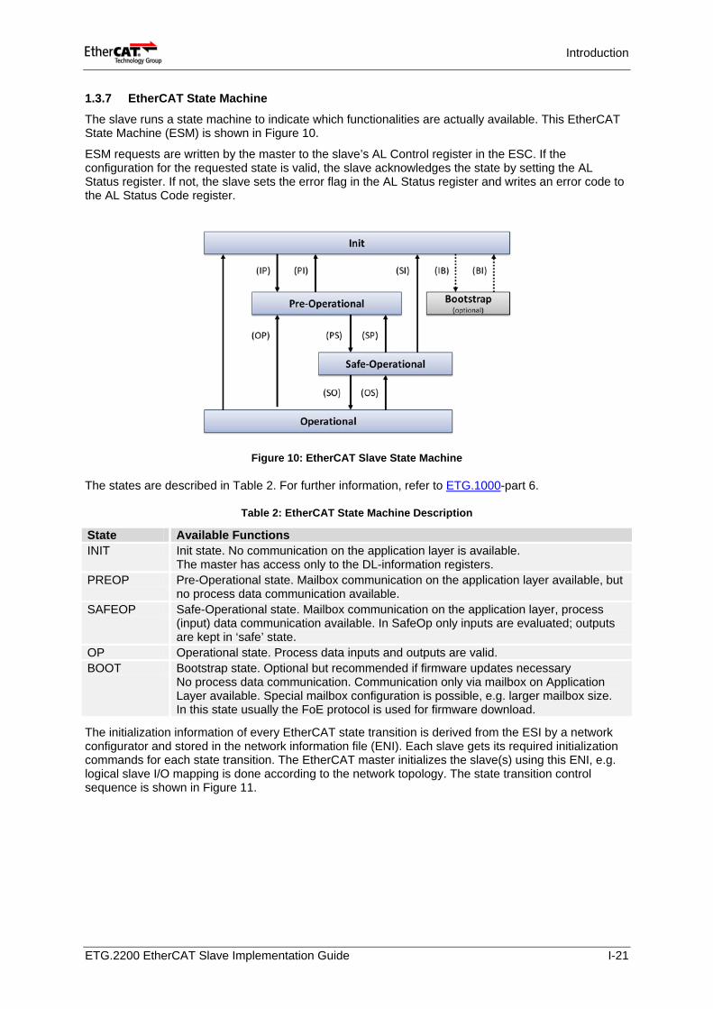
The slave runs a state machine to indicate which functionalities are actually available. This EtherCAT State Machine (ESM) is shown in Figure 10.
ESM requests are written by the master to the slave’s AL Control register in the ESC. If the configuration for the requested state is valid, the slave acknowledges the state by setting the AL Status register. If not, the slave sets the error flag in the AL Status register and writes an error code to the AL Status Code register.
Figure 10: EtherCAT Slave State Machine
The states are described in Table 2. For further information, refer to ETG.1000-part 6.
Table 2: EtherCAT State Machine Description
State Available Functions INIT Init state. No communication on the application layer is available.
The master has access only to the DL-information registers. PREOP Pre-Operational state. Mailbox communication on the application layer available, but
no process data communication available. SAFEOP Safe-Operational state. Mailbox communication on the application layer, process
(input) data communication available. In SafeOp only inputs are evaluated; outputs are kept in ‘safe’ state.
OP Operational state. Process data inputs and outputs are valid. BOOT Bootstrap state. Optional but recommended if firmware updates necessary
No process data communication. Communication only via mailbox on Application Layer available. Special mailbox configuration is possible, e.g. larger mailbox size. In this state usually the FoE protocol is used for firmware download.
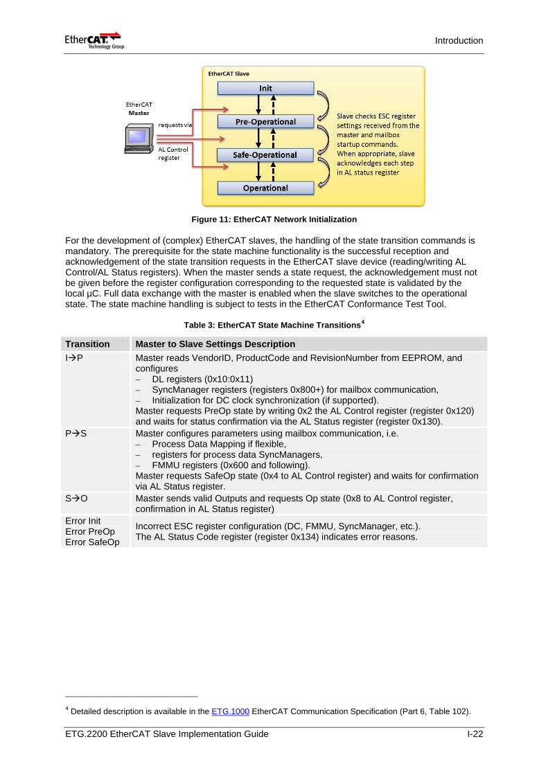
The initialization information of every EtherCAT state transition is derived from the ESI by a network configurator and stored in the network information file (ENI). Each slave gets its required initialization commands for each state transition. The EtherCAT master initializes the slave(s) using this ENI, e.g. logical slave I/O mapping is done according to the network topology. The state transition control sequence is shown in Figure 11.
ETG.2200 EtherCAT Slave Implementation Guide I-21
Introduction
Figure 11: EtherCAT Network Initialization
For the development of (complex) EtherCAT slaves, the handling of the state transition commands is mandatory. The prerequisite for the state machine functionality is the successful reception and acknowledgement of the state transition requests in the EtherCAT slave device (reading/writing AL Control/AL Status registers). When the master sends a state request, the acknowledgement must not be given before the register configuration corresponding to the requested state is validated by the local µC. Full data exchange with the master is enabled when the slave switches to the operational state. The state machine handling is subject to tests in the EtherCAT Conformance Test Tool.
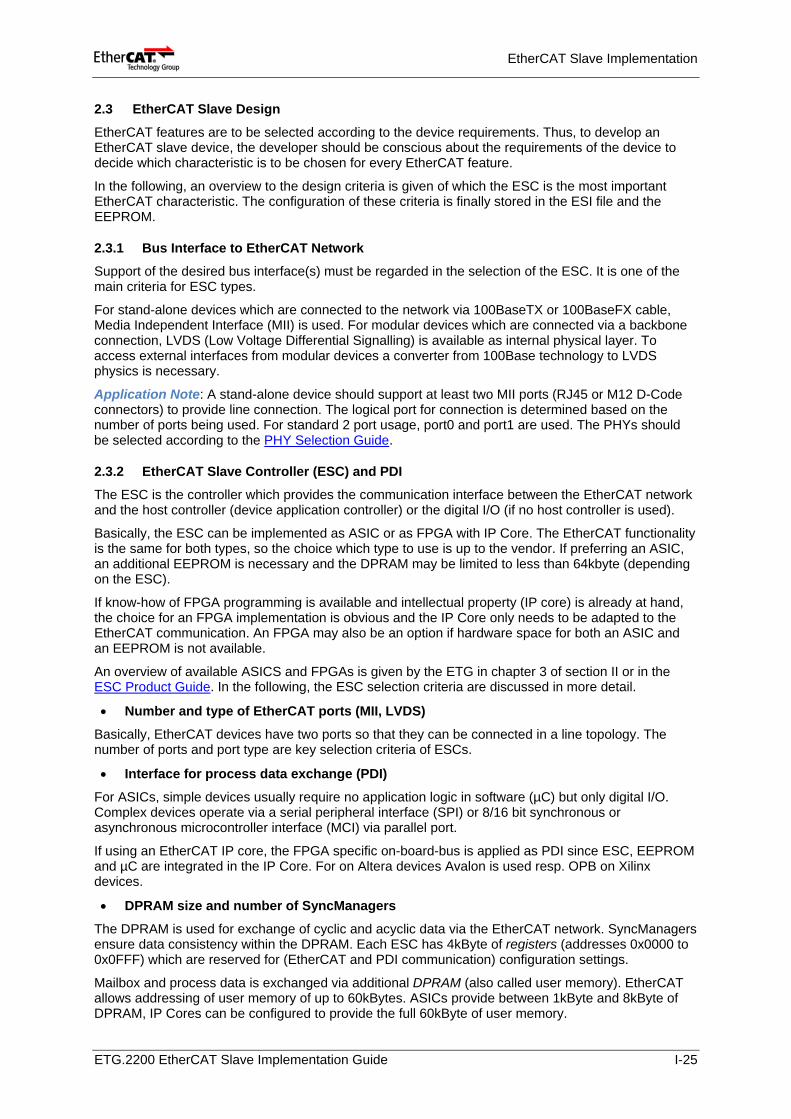
Table 3: EtherCAT State Machine Transitions4
Transition Master to Slave Settings Description IP Master reads VendorID, ProductCode and RevisionNumber from EEPROM, and
configures – DL registers (0x10:0x11) – SyncManager registers (registers 0x800+) for mailbox communication, – Initialization for DC clock synchronization (if supported). Master requests PreOp state by writing 0x2 the AL Control register (register 0x120) and waits for status confirmation via the AL Status register (register 0x130).
PS Master configures parameters using mailbox communication, i.e. – Process Data Mapping if flexible, – registers for process data SyncManagers, – FMMU registers (0x600 and following). Master requests SafeOp state (0x4 to AL Control register) and waits for confirmation via AL Status register.
SO Master sends valid Outputs and requests Op state (0x8 to AL Control register, confirmation in AL Status register)
Error Init Error PreOp Error SafeOp
Incorrect ESC register configuration (DC, FMMU, SyncManager, etc.). The AL Status Code register (register 0x134) indicates error reasons.
4 Detailed description is available in the ETG.1000 EtherCAT Communication Specification (Part 6, Table 102).
ETG.2200 EtherCAT Slave Implementation Guide I-22
EtherCAT Slave Implementation
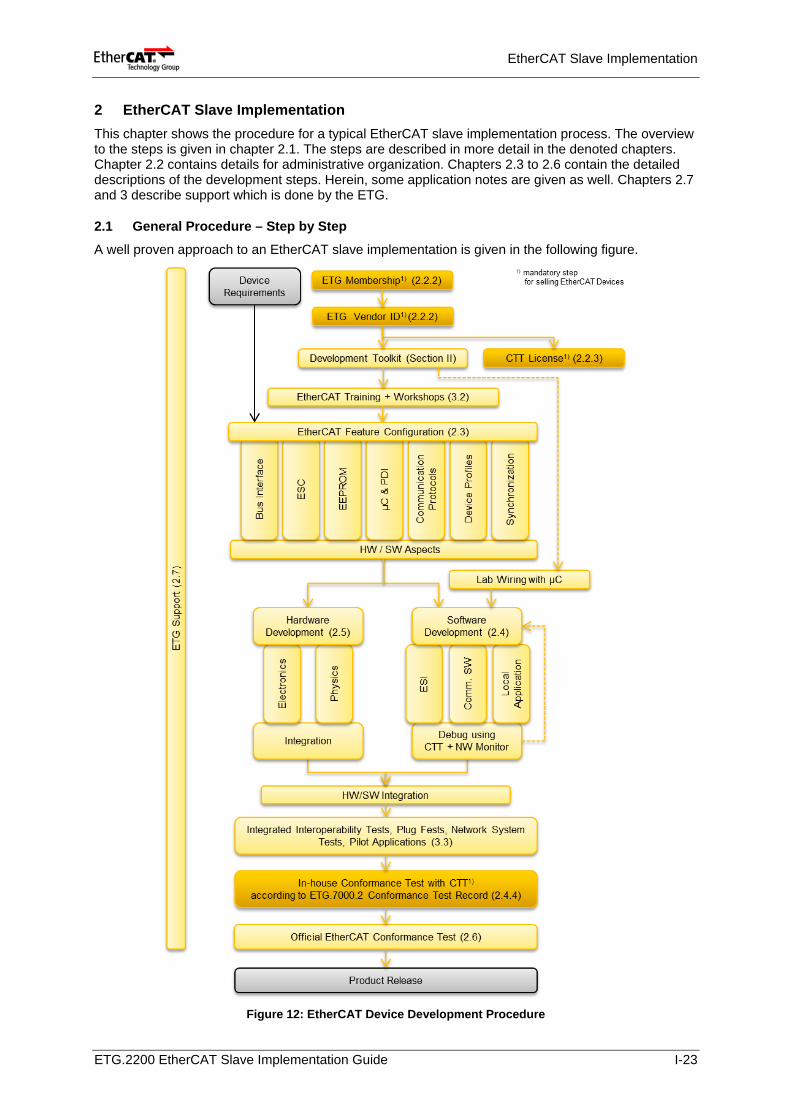
2 EtherCAT Slave Implementation This chapter shows the procedure for a typical EtherCAT slave implementation process. The overview to the steps is given in chapter 2.1. The steps are described in more detail in the denoted chapters. Chapter 2.2 contains details for administrative organization. Chapters 2.3 to 2.6 contain the detailed descriptions of the development steps. Herein, some application notes are given as well. Chapters 2.7 and 3 describe support which is done by the ETG.
2.1 General Procedure – Step by Step
A well proven approach to an EtherCAT slave implementation is given in the following figure.
Figure 12: EtherCAT Device Development Procedure
ETG.2200 EtherCAT Slave Implementation Guide I-23
EtherCAT Slave Implementation
2.2 Administrative Organization
2.2.1 Development Time To develop a new running slave system, operated by a standard EtherCAT master, about 6-8 weeks are feasible. Herein, parts of the own application development are already included.
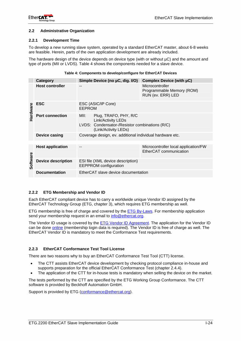
The hardware design of the device depends on device type (with or without µC) and the amount and type of ports (MII or LVDS). Table 4 shows the components needed for a slave device.
Table 4: Components to develop/configure for EtherCAT Devices
Category Simple Device (no µC, dig. I/O) Complex Device (with µC)
Har
dwar
e
Host controller -- Microcontroller Programmable Memory (ROM) RUN (ev. ERR) LED
ESC ESC (ASIC/IP Core) EEPROM
Port connection MII: Plug, TRAFO, PHY, R/C Link/Activity LEDs LVDS: Condensator-/Resistor combinations (R/C) (Link/Activity LEDs)
Device casing Coverage design, ev. additional individual hardware etc.
Softw
are
Host application -- Microcontroller local application/FW EtherCAT communication
Device description ESI file (XML device description) EEPPROM configuration
Documentation EtherCAT slave device documentation
2.2.2 ETG Membership and Vendor ID
Each EtherCAT compliant device has to carry a worldwide unique Vendor ID assigned by the EtherCAT Technology Group (ETG, chapter 3), which requires ETG membership as well.
ETG membership is free of charge and covered by the ETG By-Laws. For membership application send your membership request in an email to [email protected].
The Vendor ID usage is covered by the ETG Vendor ID Agreement. The application for the Vendor ID can be done online (membership login data is required). The Vendor ID is free of charge as well. The EtherCAT Vendor ID is mandatory to meet the Conformance Test requirements.
2.2.3 EtherCAT Conformance Test Tool License
There are two reasons why to buy an EtherCAT Conformance Test Tool (CTT) license.
• The CTT assists EtherCAT device development by checking protocol compliance in-house and supports preparation for the official EtherCAT Conformance Test (chapter 2.4.4).
• The application of the CTT for in-house tests is mandatory when selling the device on the market.
The tests performed by the CTT are specified by the ETG Working Group Conformance. The CTT software is provided by Beckhoff Automation GmbH.
Support is provided by ETG ([email protected]).
ETG.2200 EtherCAT Slave Implementation Guide I-24
EtherCAT Slave Implementation
2.3 EtherCAT Slave Design
EtherCAT features are to be selected according to the device requirements. Thus, to develop an EtherCAT slave device, the developer should be conscious about the requirements of the device to decide which characteristic is to be chosen for every EtherCAT feature.
In the following, an overview to the design criteria is given of which the ESC is the most important EtherCAT characteristic. The configuration of these criteria is finally stored in the ESI file and the EEPROM.
2.3.1 Bus Interface to EtherCAT Network Support of the desired bus interface(s) must be regarded in the selection of the ESC. It is one of the main criteria for ESC types.
For stand-alone devices which are connected to the network via 100BaseTX or 100BaseFX cable, Media Independent Interface (MII) is used. For modular devices which are connected via a backbone connection, LVDS (Low Voltage Differential Signalling) is available as internal physical layer. To access external interfaces from modular devices a converter from 100Base technology to LVDS physics is necessary.
Application Note: A stand-alone device should support at least two MII ports (RJ45 or M12 D-Code connectors) to provide line connection. The logical port for connection is determined based on the number of ports being used. For standard 2 port usage, port0 and port1 are used. The PHYs should be selected according to the PHY Selection Guide.
2.3.2 EtherCAT Slave Controller (ESC) and PDI The ESC is the controller which provides the communication interface between the EtherCAT network and the host controller (device application controller) or the digital I/O (if no host controller is used).
Basically, the ESC can be implemented as ASIC or as FPGA with IP Core. The EtherCAT functionality is the same for both types, so the choice which type to use is up to the vendor. If preferring an ASIC, an additional EEPROM is necessary and the DPRAM may be limited to less than 64kbyte (depending on the ESC).
If know-how of FPGA programming is available and intellectual property (IP core) is already at hand, the choice for an FPGA implementation is obvious and the IP Core only needs to be adapted to the EtherCAT communication. An FPGA may also be an option if hardware space for both an ASIC and an EEPROM is not available.
An overview of available ASICS and FPGAs is given by the ETG in chapter 3 of section II or in the ESC Product Guide. In the following, the ESC selection criteria are discussed in more detail.
• Number and type of EtherCAT ports (MII, LVDS)
Basically, EtherCAT devices have two ports so that they can be connected in a line topology. The number of ports and port type are key selection criteria of ESCs.
• Interface for process data exchange (PDI)
For ASICs, simple devices usually require no application logic in software (µC) but only digital I/O. Complex devices operate via a serial peripheral interface (SPI) or 8/16 bit synchronous or asynchronous microcontroller interface (MCI) via parallel port.
If using an EtherCAT IP core, the FPGA specific on-board-bus is applied as PDI since ESC, EEPROM and µC are integrated in the IP Core. For on Altera devices Avalon is used resp. OPB on Xilinx devices.
• DPRAM size and number of SyncManagers
The DPRAM is used for exchange of cyclic and acyclic data via the EtherCAT network. SyncManagers ensure data consistency within the DPRAM. Each ESC has 4kByte of registers (addresses 0x0000 to 0x0FFF) which are reserved for (EtherCAT and PDI communication) configuration settings.
Mailbox and process data is exchanged via additional DPRAM (also called user memory). EtherCAT allows addressing of user memory of up to 60kBytes. ASICs provide between 1kByte and 8kByte of DPRAM, IP Cores can be configured to provide the full 60kByte of user memory.
ETG.2200 EtherCAT Slave Implementation Guide I-25
EtherCAT Slave Implementation
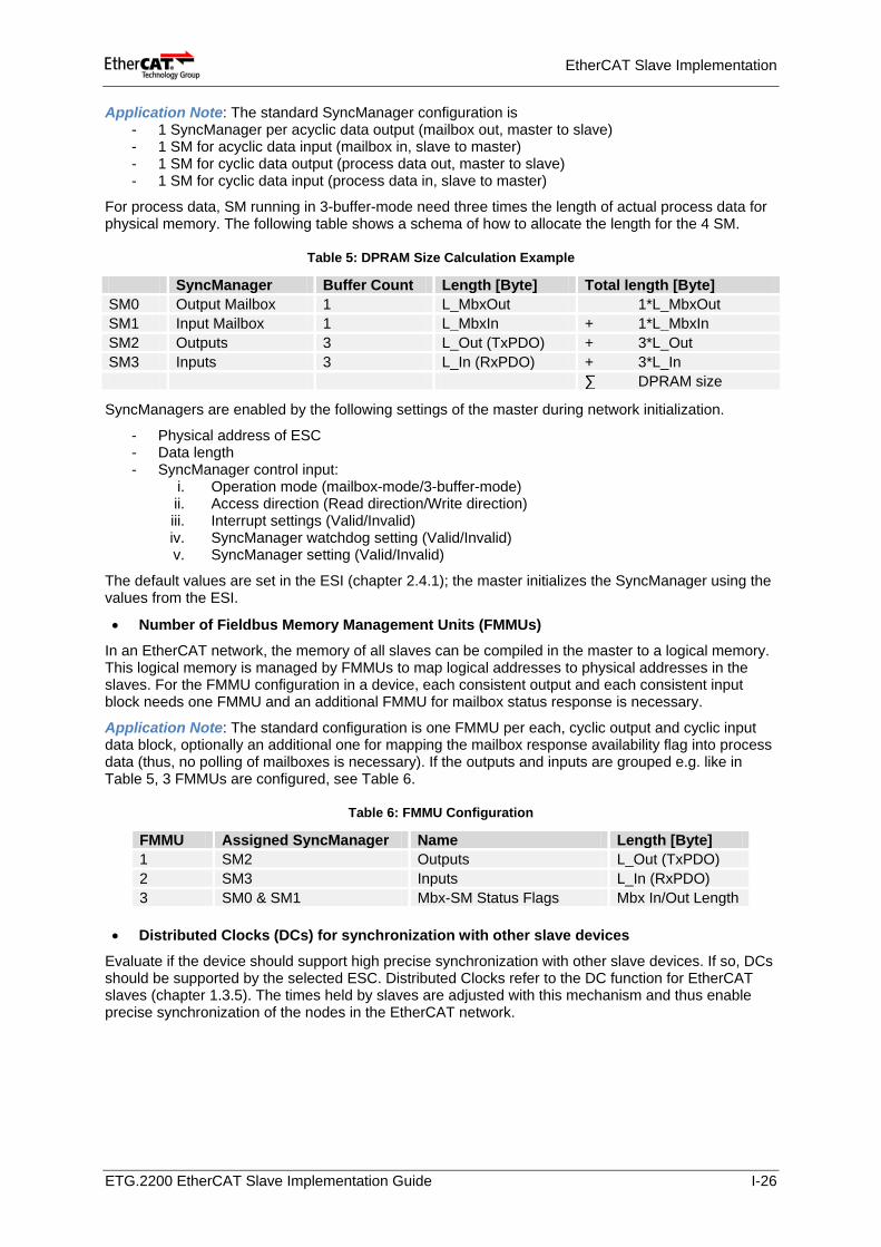
Application Note: The standard SyncManager configuration is
- 1 SyncManager per acyclic data output (mailbox out, master to slave) - 1 SM for acyclic data input (mailbox in, slave to master) - 1 SM for cyclic data output (process data out, master to slave) - 1 SM for cyclic data input (process data in, slave to master)
For process data, SM running in 3-buffer-mode need three times the length of actual process data for physical memory. The following table shows a schema of how to allocate the length for the 4 SM.
Table 5: DPRAM Size Calculation Example
SyncManager Buffer Count Length [Byte] Total length [Byte] SM0 Output Mailbox 1 L_MbxOut 1*L_MbxOut SM1 Input Mailbox 1 L_MbxIn + 1*L_MbxIn SM2 Outputs 3 L_Out (TxPDO) + 3*L_Out SM3 Inputs 3 L_In (RxPDO) + 3*L_In ∑ DPRAM size
SyncManagers are enabled by the following settings of the master during network initialization.
- Physical address of ESC - Data length - SyncManager control input:
i. Operation mode (mailbox-mode/3-buffer-mode) ii. Access direction (Read direction/Write direction) iii. Interrupt settings (Valid/Invalid) iv. SyncManager watchdog setting (Valid/Invalid) v. SyncManager setting (Valid/Invalid)
The default values are set in the ESI (chapter 2.4.1); the master initializes the SyncManager using the values from the ESI.
• Number of Fieldbus Memory Management Units (FMMUs)
In an EtherCAT network, the memory of all slaves can be compiled in the master to a logical memory. This logical memory is managed by FMMUs to map logical addresses to physical addresses in the slaves. For the FMMU configuration in a device, each consistent output and each consistent input block needs one FMMU and an additional FMMU for mailbox status response is necessary.
Application Note: The standard configuration is one FMMU per each, cyclic output and cyclic input data block, optionally an additional one for mapping the mailbox response availability flag into process data (thus, no polling of mailboxes is necessary). If the outputs and inputs are grouped e.g. like in Table 5, 3 FMMUs are configured, see Table 6.
Table 6: FMMU Configuration
FMMU Assigned SyncManager Name Length [Byte] 1 SM2 Outputs L_Out (TxPDO) 2 SM3 Inputs L_In (RxPDO) 3 SM0 & SM1 Mbx-SM Status Flags Mbx In/Out Length
• Distributed Clocks (DCs) for synchronization with other slave devices
Evaluate if the device should support high precise synchronization with other slave devices. If so, DCs should be supported by the selected ESC. Distributed Clocks refer to the DC function for EtherCAT slaves (chapter 1.3.5). The times held by slaves are adjusted with this mechanism and thus enable precise synchronization of the nodes in the EtherCAT network.
ETG.2200 EtherCAT Slave Implementation Guide I-26
EtherCAT Slave Implementation
2.3.3 EEPROM
The EEPROM is mounted outside the ESC and connected via I2C with point-to-point link. According to the size of the EEPROM the EEPROM_SIZE signal should be set. For more details, refer to the Knowledge Base, chapter 11.3 “EEPROM and electrical Interface (I2C)".
For EEPROM (SII) Enhanced Link Detection setting, refer to documentation of the ESC vendor.
2.3.4 Application Controller (Host Controller, µC)
If a local software application provides the device functionality, any 8 or 16 bit synchronous or asynchronous microcontroller can be connected to the ESC. The application controller communicates with the ESC via the Process Data Interfaces (PDI).
To adapt the application software on the host controller to the ESC, sample software stacks are available for communication implementation, e.g. the Slave Sample Code (SCC). If the device is a 32 bit digital I/O interface, no application controller or additional communication software is necessary.
In most cases, manufacturers can use a familiar microcontroller type as application controller in the EtherCAT device. If application software already exists, e.g. for a different fieldbus, it can be used for the EtherCAT device as well.
The source code for communications software on the host controller allocates about 70kByte. The following features are a typical configuration (referring to the Slave Sample Code):
• EtherCAT State Machine (ESM), including error handling • Device diagnosis • Master-Slave data synchronization with SyncManager event (no DCs) • Mailbox CoE • Object Dictionary (20 objects) for process data objects • CoE services, including CoE Info services, no segmented transfer
A list of other available sample stacks can be obtained on the product section of the ETG website.
2.3.5 Application Layer Communication Protocols
In EtherCAT, several protocols are available (see chapter 1.3.6) for the application layer to implement the required specification of the product development. When to apply them is described here.
• CAN application protocol over EtherCAT (CoE) To provide acyclic data exchange as well as mechanisms to configure PDOs for cyclic data exchange in a structured way, CoE (with SDO-Info support) should be implemented.
• Servo drive profile over EtherCAT (SoE) SoE is an alternative drive profile to the CiA402 drive profile. It is often used by drive manufacturers which are familiar with the SERCOS interface.
• Ethernet over EtherCAT (EoE) EoE is usually used to provide webserver interfaces via EtherCAT. It is also used for devices providing decentral standard Ethernet ports.
• File Access over EtherCAT (FoE) If the device should support firmware download via EtherCAT, FoE should be supported. FoE is based on TFTP. It provides fast file transfer and small protocol implementation.
• ADS over EtherCAT (AoE) When planning to control the device via a .Net interface, AoE is an option to apply.
ETG.2200 EtherCAT Slave Implementation Guide I-27
EtherCAT Slave Implementation
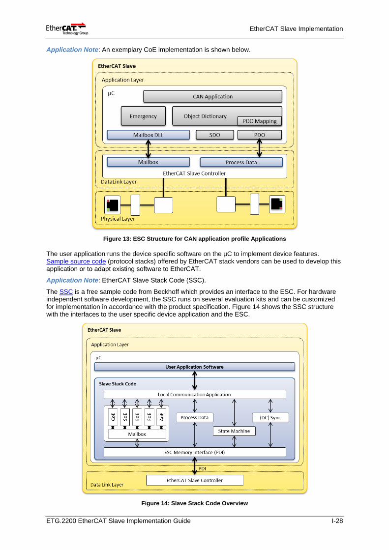
Application Note: An exemplary CoE implementation is shown below.
Figure 13: ESC Structure for CAN application profile Applications
The user application runs the device specific software on the µC to implement device features. Sample source code (protocol stacks) offered by EtherCAT stack vendors can be used to develop this application or to adapt existing software to EtherCAT.
Application Note: EtherCAT Slave Stack Code (SSC).
The SSC is a free sample code from Beckhoff which provides an interface to the ESC. For hardware independent software development, the SSC runs on several evaluation kits and can be customized for implementation in accordance with the product specification. Figure 14 shows the SSC structure with the interfaces to the user specific device application and the ESC.
Figure 14: Slave Stack Code Overview
ETG.2200 EtherCAT Slave Implementation Guide I-28
EtherCAT Slave Implementation
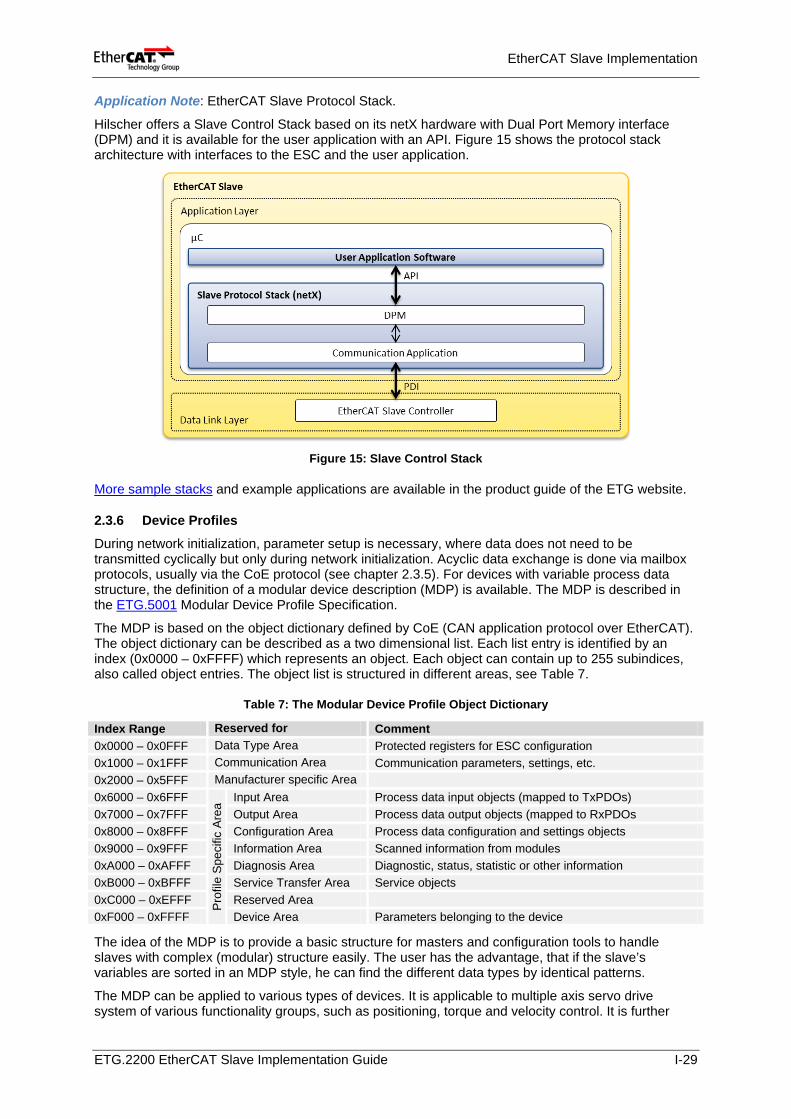
Application Note: EtherCAT Slave Protocol Stack.
Hilscher offers a Slave Control Stack based on its netX hardware with Dual Port Memory interface (DPM) and it is available for the user application with an API. Figure 15 shows the protocol stack architecture with interfaces to the ESC and the user application.
Figure 15: Slave Control Stack
More sample stacks and example applications are available in the product guide of the ETG website.
2.3.6 Device Profiles
During network initialization, parameter setup is necessary, where data does not need to be transmitted cyclically but only during network initialization. Acyclic data exchange is done via mailbox protocols, usually via the CoE protocol (see chapter 2.3.5). For devices with variable process data structure, the definition of a modular device description (MDP) is available. The MDP is described in the ETG.5001 Modular Device Profile Specification.
The MDP is based on the object dictionary defined by CoE (CAN application protocol over EtherCAT). The object dictionary can be described as a two dimensional list. Each list entry is identified by an index (0x0000 – 0xFFFF) which represents an object. Each object can contain up to 255 subindices, also called object entries. The object list is structured in different areas, see Table 7.
Table 7: The Modular Device Profile Object Dictionary
Index Range Reserved for Comment 0x0000 – 0x0FFF Data Type Area Protected registers for ESC configuration 0x1000 – 0x1FFF Communication Area Communication parameters, settings, etc. 0x2000 – 0x5FFF Manufacturer specific Area 0x6000 – 0x6FFF
Pro
file
Spe
cific
Are
a
Input Area Process data input objects (mapped to TxPDOs) 0x7000 – 0x7FFF Output Area Process data output objects (mapped to RxPDOs 0x8000 – 0x8FFF Configuration Area Process data configuration and settings objects 0x9000 – 0x9FFF Information Area Scanned information from modules 0xA000 – 0xAFFF Diagnosis Area Diagnostic, status, statistic or other information 0xB000 – 0xBFFF Service Transfer Area Service objects 0xC000 – 0xEFFF Reserved Area 0xF000 – 0xFFFF Device Area Parameters belonging to the device
The idea of the MDP is to provide a basic structure for masters and configuration tools to handle slaves with complex (modular) structure easily. The user has the advantage, that if the slave’s variables are sorted in an MDP style, he can find the different data types by identical patterns.
The MDP can be applied to various types of devices. It is applicable to multiple axis servo drive system of various functionality groups, such as positioning, torque and velocity control. It is further
ETG.2200 EtherCAT Slave Implementation Guide I-29
EtherCAT Slave Implementation
applicable to gateway between different fieldbuses, i.e., Profibus, DeviceNet. Modular devices are driven by two aspects:
• Comprise physically connectable modules and plurality of functionalities. • Comprise plurality of channels directly being connected to the EtherCAT network.
The MDP imagines slaves which consist of one or several modules. A module can be hardware which is connected/disconnected to a slave. Examples are gateways between EtherCAT and e.g. CANopen or a bus coupler between EtherCAT and a proprietary backbone bus.
A module can also be a logical module which describes data sets, e.g. a drive which supports a velocity controlled mode and a position controlled mode – the MDP would describe the data as two modules, one for each mode.
No matter what kind of module is described it needs more or less the same information categories, which are organized in the profile specific index range (Table 7).
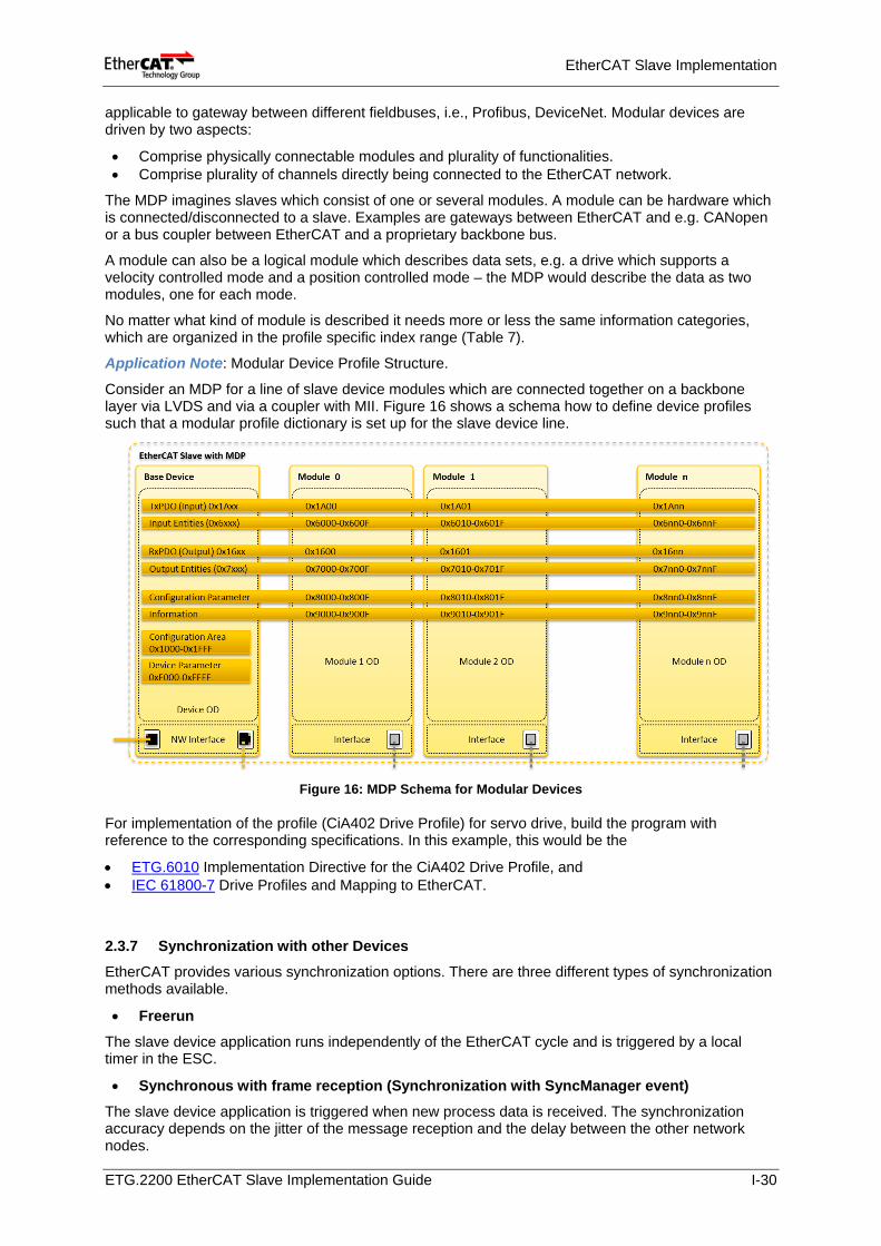
Application Note: Modular Device Profile Structure.
Consider an MDP for a line of slave device modules which are connected together on a backbone layer via LVDS and via a coupler with MII. Figure 16 shows a schema how to define device profiles such that a modular profile dictionary is set up for the slave device line.
Figure 16: MDP Schema for Modular Devices
For implementation of the profile (CiA402 Drive Profile) for servo drive, build the program with reference to the corresponding specifications. In this example, this would be the
• ETG.6010 Implementation Directive for the CiA402 Drive Profile, and • IEC 61800-7 Drive Profiles and Mapping to EtherCAT.
2.3.7 Synchronization with other Devices EtherCAT provides various synchronization options. There are three different types of synchronization methods available.
• Freerun
The slave device application runs independently of the EtherCAT cycle and is triggered by a local timer in the ESC.
• Synchronous with frame reception (Synchronization with SyncManager event)
The slave device application is triggered when new process data is received. The synchronization accuracy depends on the jitter of the message reception and the delay between the other network nodes.
ETG.2200 EtherCAT Slave Implementation Guide I-30
EtherCAT Slave Implementation
• Distributed Clocks (DC, Synchronization with SYNC0/SYNC1 event)
The ESCs contain a nanosecond based timer (DC timer) to provide precise synchronization and time stamping. The slave device application is triggered with an additional interrupt signal, which is based on the DC time and is produced by the ESC. Every DC timer in the network is aligned to a master DC clock and provides a high precise synchronization.
Application Note: The ESC system time is stored in a 64 bit value. This data size allows representation of more than 500 years. The latter 32 bits represent approximately 4.2 seconds. Refer to the datasheet of the applied ESC for details since some ESC use 32 bit length.
Initial value: 00:00:00 January 1, 2001 Unit: 1ns
Definition of a Reference Clock (RC)
One EtherCAT slave (which usually is the first slave that uses DC) is determined as the reference clock (RC) and becomes the clock base for the master as well as for other DC slaves. The reference clock is periodically provided to other slaves. The reference clock is adjustable by an external "global reference clock".
Function and Operation of DC
The slave synchronization is established during initialization of the ENI in the master. With EtherCAT, the 3 DC time synchronization functions enable highly accurate timing synchronization.
– Measurement/Calculation of the propagation delay time
During initialization procedure of the network, the master calculates the propagation delay, including the delay caused by cables and ESC, and sets the delay as slave delay. The delay calculation algorithm is basically defined the ETG.1000-part4 EtherCAT Communication specification and further described e.g. in the ET1100 Datasheet (section I, chapter 9.1.2). After establishment of the slave DC, the master periodically writes the RC time information to the other DC slaves.
– Drift compensation
The master periodically reads out the time information of the RC slave and sends a command (ARMW or FRMW) to write the time information into other DC slaves (enabled by one single datagram). The deviation of time data held by the slave is thus minimized.
– Offset compensation:
Offset compensation refers to function of adjusting the system time held by the EtherCAT master and the time held by slave. The slave can be synchronized by the EtherCAT master by writing into the slave the deviation of time between the system time of the master and the RC.
Interrupt signal
After establishment of DC by the master, the ESC generates fixed time interrupt signals to the PDI, i.e. the µC. Thus, the slave is able to create a constant period. There are following 3 types of generation of interrupt signals.
– SYNC/LATCH0 – SYNC/LATCH1 – IRQ (Interrupt occurs by generation of SYNC0/SYNC1and mask register setting)
Note that the SYNC0/SYNC1 interrupt signals cannot be used when using the ESC LATCH0/LATCH1 function. This restriction is due to SYNC/LATCH signal lines being a shared pin.
The latch function is a function which maintains time stamp in response to latch signal input on the ESC, and activate/deactivate timing edges can be set
ETG.2200 EtherCAT Slave Implementation Guide I-31
EtherCAT Slave Implementation
2.4 Tools for EtherCAT Slave Development
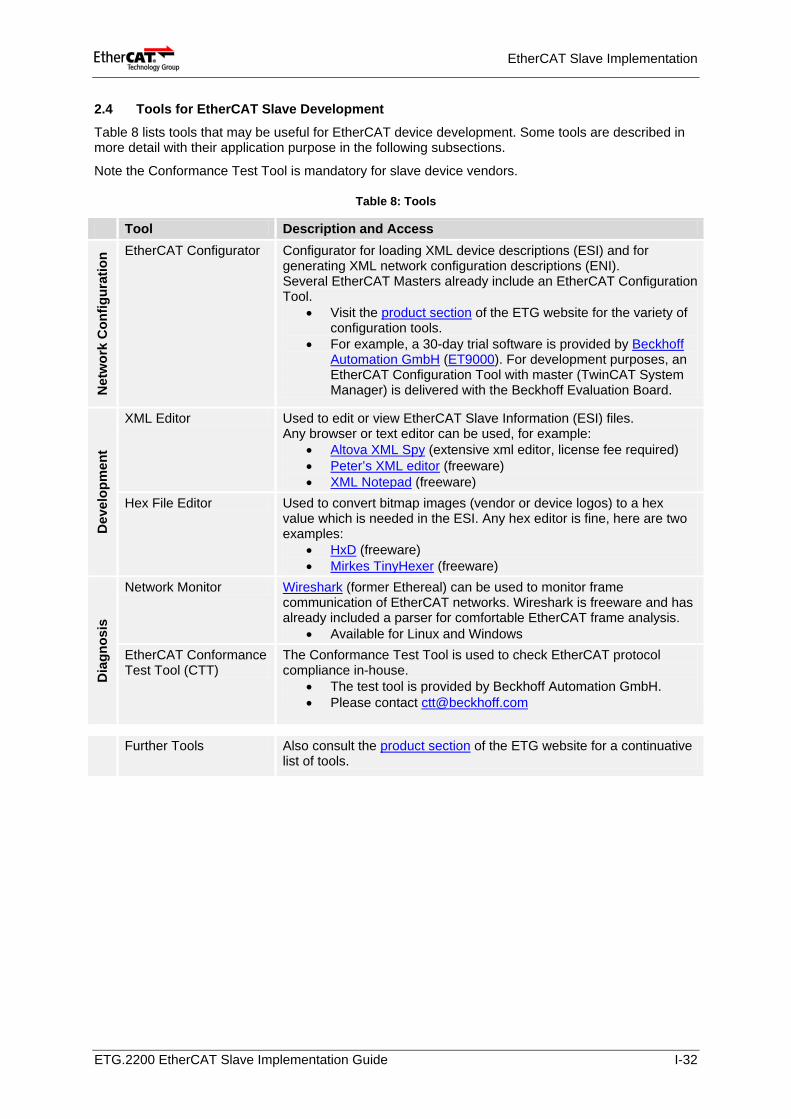
Table 8 lists tools that may be useful for EtherCAT device development. Some tools are described in more detail with their application purpose in the following subsections.
Note the Conformance Test Tool is mandatory for slave device vendors.
Table 8: Tools
Tool Description and Access
Net
wor
k C
onfig
urat
ion EtherCAT Configurator Configurator for loading XML device descriptions (ESI) and for
generating XML network configuration descriptions (ENI). Several EtherCAT Masters already include an EtherCAT Configuration Tool.
• Visit the product section of the ETG website for the variety of configuration tools.
• For example, a 30-day trial software is provided by Beckhoff Automation GmbH (ET9000). For development purposes, an EtherCAT Configuration Tool with master (TwinCAT System Manager) is delivered with the Beckhoff Evaluation Board.
Dev
elop
men
t
XML Editor Used to edit or view EtherCAT Slave Information (ESI) files. Any browser or text editor can be used, for example:
• Altova XML Spy (extensive xml editor, license fee required) • Peter’s XML editor (freeware) • XML Notepad (freeware)
Hex File Editor Used to convert bitmap images (vendor or device logos) to a hex value which is needed in the ESI. Any hex editor is fine, here are two examples:
• HxD (freeware) • Mirkes TinyHexer (freeware)
Dia
gnos
is
Network Monitor Wireshark (former Ethereal) can be used to monitor frame communication of EtherCAT networks. Wireshark is freeware and has already included a parser for comfortable EtherCAT frame analysis.
• Available for Linux and Windows EtherCAT Conformance Test Tool (CTT)
The Conformance Test Tool is used to check EtherCAT protocol compliance in-house.
• The test tool is provided by Beckhoff Automation GmbH. • Please contact [email protected]
Further Tools Also consult the product section of the ETG website for a continuative list of tools.
ETG.2200 EtherCAT Slave Implementation Guide I-32
EtherCAT Slave Implementation
2.4.1 XML Editor for Generating ESI files
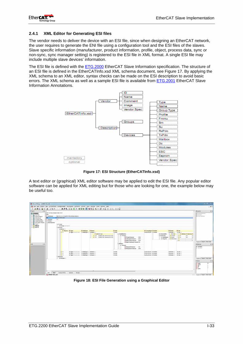
The vendor needs to deliver the device with an ESI file, since when designing an EtherCAT network, the user requires to generate the ENI file using a configuration tool and the ESI files of the slaves. Slave specific information (manufacturer, product information, profile, object, process data, sync or non-sync, sync manager setting) is registered to the ESI file in XML format. A single ESI file may include multiple slave devices’ information.
The ESI file is defined with the ETG.2000 EtherCAT Slave Information specification. The structure of an ESI file is defined in the EtherCATInfo.xsd XML schema document, see Figure 17. By applying the XML schema to an XML editor, syntax checks can be made on the ESI description to avoid basic errors. The XML schema as well as a sample ESI file is available from ETG.2001 EtherCAT Slave Information Annotations.
Figure 17: ESI Structure (EtherCATInfo.xsd)
A text editor or (graphical) XML editor software may be applied to edit the ESI file. Any popular editor software can be applied for XML editing but for those who are looking for one, the example below may be useful too.
Figure 18: ESI File Generation using a Graphical Editor
ETG.2200 EtherCAT Slave Implementation Guide I-33
EtherCAT Slave Implementation
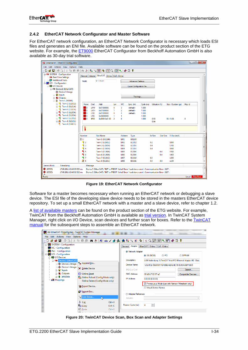
2.4.2 EtherCAT Network Configurator and Master Software
For EtherCAT network configuration, an EtherCAT Network Configurator is necessary which loads ESI files and generates an ENI file. Available software can be found on the product section of the ETG website. For example, the ET9000 EtherCAT Configurator from Beckhoff Automation GmbH is also available as 30-day trial software.
Figure 19: EtherCAT Network Configurator
Software for a master becomes necessary when running an EtherCAT network or debugging a slave device. The ESI file of the developing slave device needs to be stored in the masters EtherCAT device repository. To set up a small EtherCAT network with a master and a slave device, refer to chapter 1.2.
A list of available masters can be found on the product section of the ETG website. For example, TwinCAT from the Beckhoff Automation GmbH is available as trial version. In TwinCAT System Manager, right click on I/O Device, scan devices and further scan for boxes. Refer to the TwinCAT manual for the subsequent steps to assemble an EtherCAT network.
Figure 20: TwinCAT Device Scan, Box Scan and Adapter Settings
ETG.2200 EtherCAT Slave Implementation Guide I-34
EtherCAT Slave Implementation
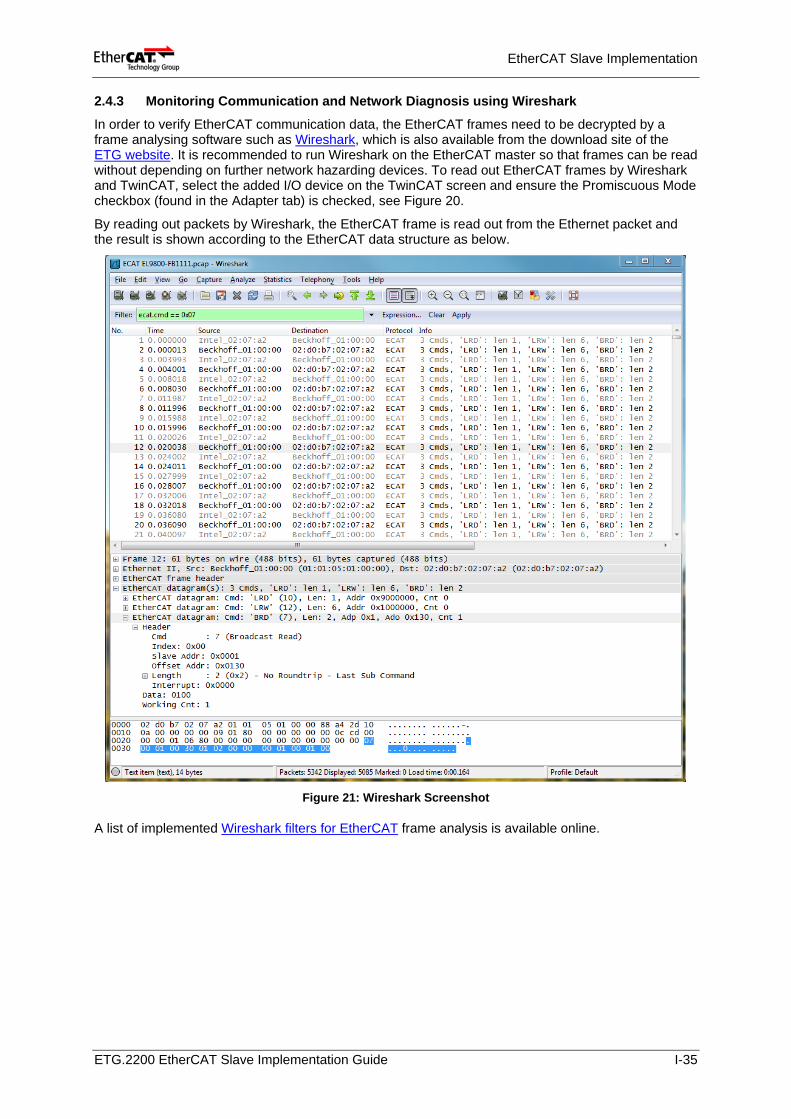
2.4.3 Monitoring Communication and Network Diagnosis using Wireshark
In order to verify EtherCAT communication data, the EtherCAT frames need to be decrypted by a frame analysing software such as Wireshark, which is also available from the download site of the ETG website. It is recommended to run Wireshark on the EtherCAT master so that frames can be read without depending on further network hazarding devices. To read out EtherCAT frames by Wireshark and TwinCAT, select the added I/O device on the TwinCAT screen and ensure the Promiscuous Mode checkbox (found in the Adapter tab) is checked, see Figure 20.
By reading out packets by Wireshark, the EtherCAT frame is read out from the Ethernet packet and the result is shown according to the EtherCAT data structure as below.
Figure 21: Wireshark Screenshot
A list of implemented Wireshark filters for EtherCAT frame analysis is available online.
ETG.2200 EtherCAT Slave Implementation Guide I-35
EtherCAT Slave Implementation
2.4.4 EtherCAT Conformance Test Tool for Debugging
Besides of basic software and hardware debugging, in-house EtherCAT conformance testing is mandatory to verify that the device meets the EtherCAT communication requirements. Meeting this requirement is a minimum condition to sell the product as the EtherCAT compatible product. In-house EtherCAT conformance testing is done with the EtherCAT Conformance Test Tool (CTT).
Application Note: To build a conformance test environment, the following items should be prepared.
• Windows PC + network card (100Mbit, full duplex and auto negotiation must be supported) • CTT, (ET9400) available from Beckhoff (see chapter 2.2.3).
NOTE: Download and install the latest CTT version. The CTT is updated periodically; therefore you need to purchase a one-year license to be always up to date. When a CTT update is available, Beckhoff will send a notification with account information and the download URL to all CTT licensees.
• The device which is to test (DuT) • Device description file (ESI) • Packet analysing software (e.g. Wireshark)
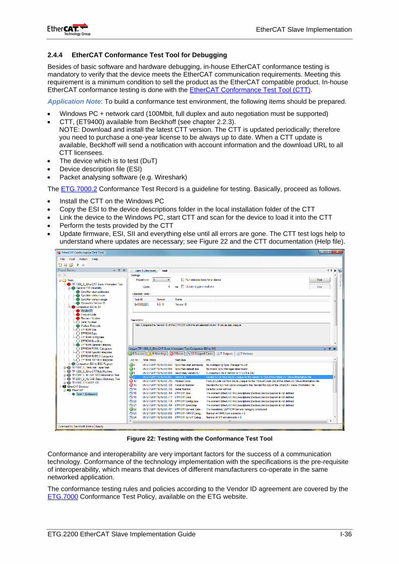
The ETG.7000.2 Conformance Test Record is a guideline for testing. Basically, proceed as follows.
• Install the CTT on the Windows PC • Copy the ESI to the device descriptions folder in the local installation folder of the CTT • Link the device to the Windows PC, start CTT and scan for the device to load it into the CTT • Perform the tests provided by the CTT • Update firmware, ESI, SII and everything else until all errors are gone. The CTT test logs help to
understand where updates are necessary; see Figure 22 and the CTT documentation (Help file).
Figure 22: Testing with the Conformance Test Tool
Conformance and interoperability are very important factors for the success of a communication technology. Conformance of the technology implementation with the specifications is the pre-requisite of interoperability, which means that devices of different manufacturers co-operate in the same networked application.
The conformance testing rules and policies according to the Vendor ID agreement are covered by the ETG.7000 Conformance Test Policy, available on the ETG website.
ETG.2200 EtherCAT Slave Implementation Guide I-36
EtherCAT Slave Implementation
2.5 EtherCAT Product Labels and LEDs
It is recommended to consider the LEDs, device identification and captioning (e.g. of the ports) during the devices hardware design. This is subject of the ETG.9001 Marking Rules and the ETG.1300 Indicator Specification and Labelling Specification.
EtherCAT obligates various elements for indication. Such indication should be made as markings on the surface of EtherCAT slave box. The marking requirements are also the subject elements of the ETC conformance test (ETG.7000.2 Conformance Test Record).
Activity of EtherCAT devices is indicated by LEDs, which indicate the
- Current state of the state machine: Init, PreOp, SafeOp, Op (RUN LED) - Error code (ERR LED) - Link/Activity of the ports (L/A LED)
Application Note: Referring to the ETG.1300 Indicator and Labelling specification, the LEDs must work as shown in the following table.
Table 9: RUN and ERR LED Indications
RUN LED EtherCAT State ERR LED EtherCAT State Off Init Off No Error Blinking Pre-Operational Blinking Invalid Configuration Single Flash Safe-Operational Single Flash Unsolicited State Change Double Flash Application Watchdog Timeout Flashes Initialization or Bootstrap Flickering Booting Error On Operational On PDI Watchdog Timeout
Application Note: EtherCAT Branding. At least one of the following EtherCAT logos should show on the product or instruction manual:
Figure 23: EtherCAT Product Branding Logos
The following English declaration of the EtherCAT trademark must appear in the instruction manual:
“EtherCAT® is a registered trademark and patented technology, licensed by Beckhoff Automation GmbH, Germany.”
Application Note: Requirements for port labels and L/A LED indication derived from the ETG.1300 Indicator and Labelling specification.
Table 10: Port and L/A LED Label Requirements
Label type Requirements IN port label Must be placed near the port. The label should be clearly allocated to the
subject port the characters on the label should be one of the following "In" or "ECAT IN" (Capitals and small characters both permitted).
OUT port label Must be placed near the port. The label should be clearly allocated to the subject port. The characters on the label should be one of the following "Out" or "ECAT Out" (Capitals and small characters both permitted).
L/A LED label Preferably the print characters should be placed directly next to the network interface but is not compulsory. The mark can be placed on other location or can be omitted. The print characters, if not omitted, should show one of the following phrases. "L/A", "Link/Act" or "Link/Activity" (Capitals and small characters both permitted). Label is required on removable connectors.
ETG.2200 EtherCAT Slave Implementation Guide I-37
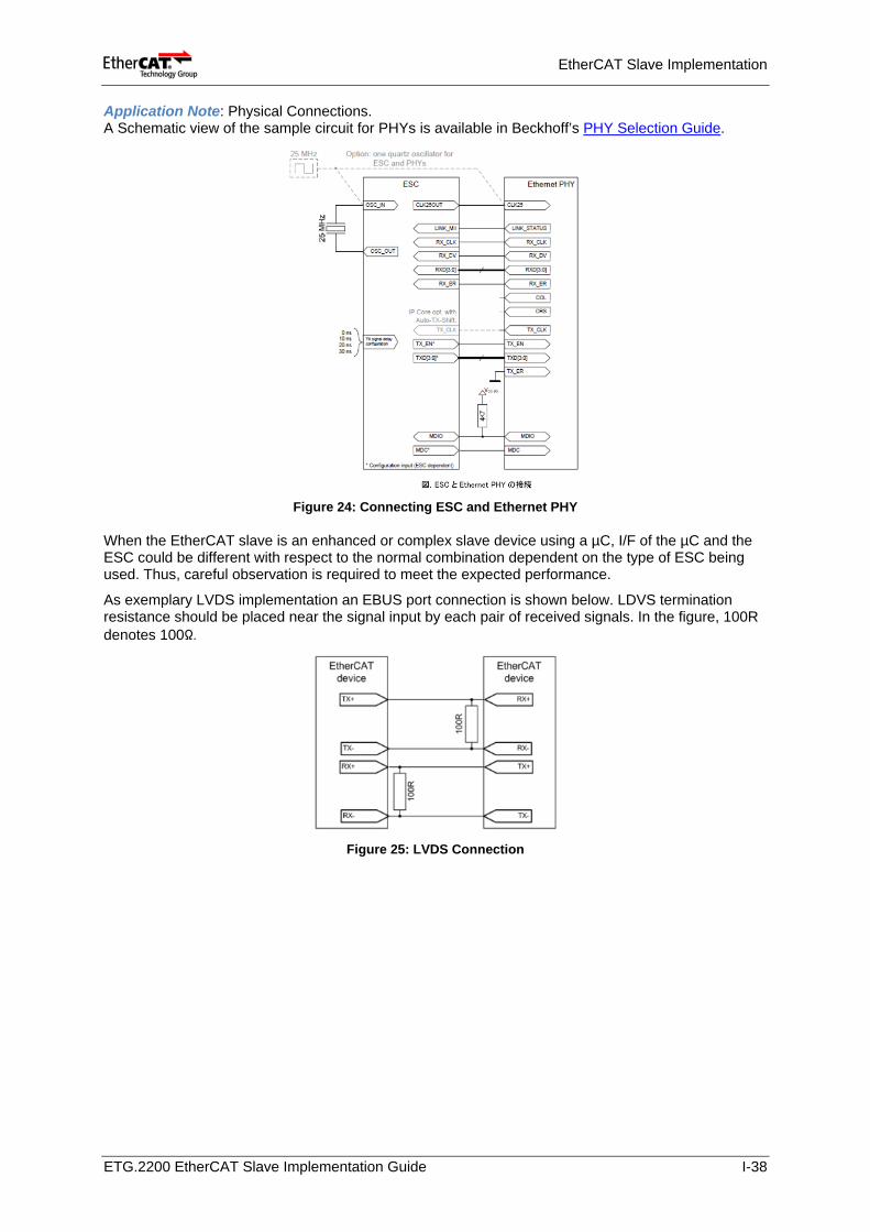
EtherCAT Slave Implementation
Application Note: Physical Connections. A Schematic view of the sample circuit for PHYs is available in Beckhoff’s PHY Selection Guide.
Figure 24: Connecting ESC and Ethernet PHY
When the EtherCAT slave is an enhanced or complex slave device using a µC, I/F of the µC and the ESC could be different with respect to the normal combination dependent on the type of ESC being used. Thus, careful observation is required to meet the expected performance.
As exemplary LVDS implementation an EBUS port connection is shown below. LDVS termination resistance should be placed near the signal input by each pair of received signals. In the figure, 100R denotes 100Ω.
Figure 25: LVDS Connection
ETG.2200 EtherCAT Slave Implementation Guide I-38
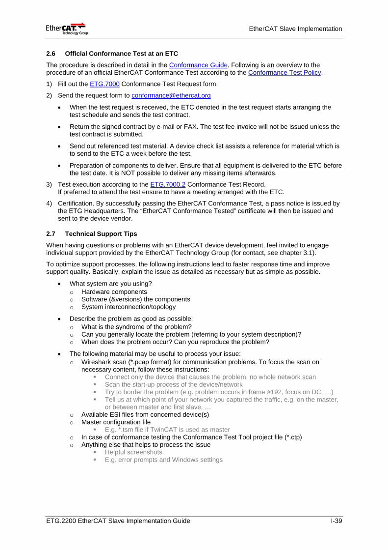
EtherCAT Slave Implementation
2.6 Official Conformance Test at an ETC
The procedure is described in detail in the Conformance Guide. Following is an overview to the procedure of an official EtherCAT Conformance Test according to the Conformance Test Policy.
1) Fill out the ETG.7000 Conformance Test Request form.
2) Send the request form to [email protected]
• When the test request is received, the ETC denoted in the test request starts arranging the test schedule and sends the test contract.
• Return the signed contract by e-mail or FAX. The test fee invoice will not be issued unless the test contract is submitted.
• Send out referenced test material. A device check list assists a reference for material which is to send to the ETC a week before the test.
• Preparation of components to deliver. Ensure that all equipment is delivered to the ETC before the test date. It is NOT possible to deliver any missing items afterwards.
3) Test execution according to the ETG.7000.2 Conformance Test Record. If preferred to attend the test ensure to have a meeting arranged with the ETC.
4) Certification. By successfully passing the EtherCAT Conformance Test, a pass notice is issued by the ETG Headquarters. The “EtherCAT Conformance Tested” certificate will then be issued and sent to the device vendor.
2.7 Technical Support Tips When having questions or problems with an EtherCAT device development, feel invited to engage individual support provided by the EtherCAT Technology Group (for contact, see chapter 3.1).
To optimize support processes, the following instructions lead to faster response time and improve support quality. Basically, explain the issue as detailed as necessary but as simple as possible.
• What system are you using? o Hardware components o Software (&versions) the components o System interconnection/topology
• Describe the problem as good as possible: o What is the syndrome of the problem? o Can you generally locate the problem (referring to your system description)? o When does the problem occur? Can you reproduce the problem?
• The following material may be useful to process your issue: o Wireshark scan (*.pcap format) for communication problems. To focus the scan on
necessary content, follow these instructions: Connect only the device that causes the problem, no whole network scan Scan the start-up process of the device/network Try to border the problem (e.g. problem occurs in frame #192, focus on DC, …) Tell us at which point of your network you captured the traffic, e.g. on the master,
or between master and first slave, … o Available ESI files from concerned device(s) o Master configuration file
E.g. *.tsm file if TwinCAT is used as master o In case of conformance testing the Conformance Test Tool project file (*.ctp) o Anything else that helps to process the issue
Helpful screenshots E.g. error prompts and Windows settings
ETG.2200 EtherCAT Slave Implementation Guide I-39
EtherCAT Technology Group – Events and Support
3 EtherCAT Technology Group – Events and Support The EtherCAT Technology Group (ETG) is the forum where key user companies from various industries and leading automation suppliers join forces to support, promote and advance the EtherCAT technology.
3.1 Basic Information about the ETG
Goals EtherCAT is an open technology. The ETG stands for this approach and ensures that every interested company may implement and use EtherCAT.
At the same time the ETG aims to ensure the compatibility of EtherCAT implementations by defining functional requirements, conformance tests as well as certification procedures.
The ETGs goal is to ensure that EtherCAT technology meets and exceeds the requirements of the widest possible application range. In order to accomplish this goal the group combines leading control and application experts from machine builders, system integrators, end users and automation suppliers to provide both qualified feedback about application of the existing technology and proposals for future extensions of the specification.
The ETG organizes user and vendor meetings in which the latest EtherCAT developments are reviewed and discussed in regular periodical sessions.
Benefits for ETG Members
ETG members get preferred access to specifications, specification drafts, white papers, prototype evaluation products and initial batch products and thus have a head start in evaluating, using or implementing the EtherCAT technology.
The members are eligible to participate in working groups and thus have influence on future enhancements of the EtherCAT technology specifications.
The member companies may use the EtherCAT and the ETG logos to show their support for this technology.
How to join the ETG
If you are interested in becoming a member of the ETG, please contact the ETG headquarters for further information resp. membership request (see contacts following).
Membership Costs
The membership is free of charge, thus there are no annual membership fees. According the ETG by-laws a membership fee can only be introduced if the membership assembly decides so.
Technical Support
Technical support throughout the development process is provided by the ETG predominately by the headquarters in Germany, but also by the various ETG offices worldwide (depending on local capacity). If you need direct contact, please address your specific question to the ETG.
Before contacting ETG for support, we expect reading the mentioned documentation above as well as the recently listed information below (i.e. chapter 2.7). We strongly recommend visiting one of the EtherCAT workshops and/or seminars for developers when starting an EtherCAT implementation.
Also a good opportunity to ask for technical experience with EtherCAT and for technical questions is provided by the EtherCAT Forum and the EtherCAT Knowledge Base within the member section of the EtherCAT website.
ETG.2200 EtherCAT Slave Implementation Guide I-40
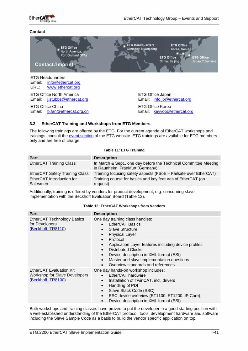
EtherCAT Technology Group – Events and Support
Contact
ETG Headquarters Email: [email protected] URL: www.ethercat.org
ETG Office North America Email: [email protected]
ETG Office China Email: [email protected]
ETG Office Japan Email: [email protected]
ETG Office Korea Email: [email protected]
3.2 EtherCAT Training and Workshops from ETG Members
The following trainings are offered by the ETG. For the current agenda of EtherCAT workshops and trainings, consult the event section of the ETG website. ETG trainings are available for ETG members only and are free of charge.
Table 11: ETG Training
Additionally, training is offered by vendors for product development, e.g. concerning slave implementation with the Beckhoff Evaluation Board (Table 12).
Table 12: EtherCAT Workshops from Vendors
Both workshops and training classes have proved to put the developer in a good starting position with a well-established understanding of the EtherCAT protocol, tools, development hardware and software including the Slave Sample Code as a basis to build the vendor specific application on top.
Part Description EtherCAT Training Class In March & Sept., one day before the Technical Committee Meeting
in Raunheim, Frankfurt (Germany). EtherCAT Safety Training Class Training focusing safety aspects (FSoE – Failsafe over EtherCAT) EtherCAT Introduction for Salesmen
Training course for basics and key features of EtherCAT (on request)
Part Description EtherCAT Technology Basics for Developers (Beckhoff, TR8110)
One day training class handles: • EtherCAT Basics • Slave Structure • Physical Layer • Protocol • Application Layer features including device profiles • Distributed Clocks • Device description in XML format (ESI) • Master and slave implementation questions • Overview standards and references
EtherCAT Evaluation Kit Workshop for Slave Developers (Beckhoff, TR8100)
One day hands-on workshop includes: • EtherCAT hardware • Installation of TwinCAT, incl. drivers • Handling of PDI • Slave Stack Code (SSC) • ESC device overview (ET1100, ET1200, IP Core) • Device description in XML format (ESI)
ETG.2200 EtherCAT Slave Implementation Guide I-41
EtherCAT Technology Group – Events and Support
3.3 Plug Fests
Depending on the demand of ETG companies, Plug Fests are held several times a year. Every ETG member developing devices or tools with at least a functional prototype are allowed to attend. In practical tests interoperability and the latest features of the devices are tested and the EtherCAT Slave Conformance Test Tool is applied. Qualified feedback of EtherCAT specialists is provided.
Dates are published on the events section of the ETG website. An additional invitation email is automatically sent to the ETG representatives of the ETG member companies.
Participation at Plug Fests is free of charge. Attendees are not entitled to publish or communicate test results of other participating companies.
3.4 Official EtherCAT Conformance Test Certificate
An official EtherCAT Conformance Test is at option after successful in-house testing. With passing the EtherCAT Conformance Test successfully a “Conformance Tested” certificate is issued and thus, the vendor may label his device with the official conformance test mark and use the term for advertisement for the certified device exclusively.
Figure 26: EtherCAT Conformance Test Logos
To apply for the EtherCAT Conformance Test at any EtherCAT Test Centre (ETC) send an Email to [email protected] to ask for further information and the request form. On return of the request form to the ETG the requested ETC will contact you for further steps (see chapter 2.6).
The Conformance Guide explains the most important details on the topic and gives advice for preparation of the Conformance Test.
There are two official authentication test centres, one in Nuremberg, Germany, and one at ASTEM in Kyoto, Japan. The ETCs do not only perform the official conformance test, but also provide qualified feedback and implementation support for ETG members.
The official test performed by an ETC is referred as "EtherCAT Conformance Test" which is regarded as higher-level test above all other tests performed individually by the users (with the CTT) since interoperability and physical layer tests are covered as well.
When successfully passed the EtherCAT Conformance Test at an ETC, a notice is given to the ETG Headquarter. An “EtherCAT Conformance Tested” certificate is then issued and sent to the device vendor. Having obtained the Conformance Tested certificate the vendor may label the device with the official conformance test mark. The vendor may use the term for advertisement for the certified device exclusively.
The test fee differs by the ETCs. Please contact the ETC-Nuremberg directly for the test fee and further information. See the URL below for the list of ETCs and contact.
3.5 Technical Committee
The TC serves as central technical board. It establishes working groups, task forces and receives their reports. Other duties of the TC are to inform about enhancements of the EtherCAT technology, progress on standardization and to discuss current technical issues with the attending ETG members.
Dates are published on the events section of the ETG website. An additional invitation email is automatically sent to the ETG representatives of the ETG member companies.
Participation at the TCs is free of charge.
ETG.2200 EtherCAT Slave Implementation Guide I-42
EtherCAT Technology Group – Events and Support
3.6 Forum
On the EtherCAT Forum, every ETG member is invited to discuss the EtherCAT technology and to post own requests. Many practical questions are already answered in the following forum topics:
• EtherCAT Specifications o Proposals
• Implementing EtherCAT o Master and Slave Devices o Evaluation Kit Hardware and Software
• EtherCAT Slave Conformance Test o Test Cases o Slave Conformance Test Tool
• EtherCAT Technology Group o ETG Services o New Downloads
• EtherCAT.org Website o Suggestions for improvements and comments
3.7 Knowledge Base
The Knowledge Base is an additional source for information about EtherCAT technology.
3.8 Technical Support
When having questions during EtherCAT device development, feel invited to engage individual support provided by the ETG. For support tips, see chapter 2.7.
ETG.2200 EtherCAT Slave Implementation Guide I-43
EtherCAT Technology Group – Events and Support
ETG.2200 EtherCAT Slave Implementation Guide I-44
EtherCAT Slave Implementation Guide
Slave Implementation Guide
SECTION II – Development Components
EtherCAT Development Products, Evaluation Kits, Slave Controllers, Communication Modules, Implementation Specifics
CONTENTS
CONTENTS
Document: ETG.2200 V2.1.0 .......................................................................................................1
SECTION I – EtherCAT Slave Introduction and Implementation Procedure ...........................................5
1 Introduction ...................................................................................................................................11
1.1 Documents for Detailed Information and Further Reading ......................................11
1.2 EtherCAT System Architecture ................................................................................13
1.2.1 Configuration Tool ....................................................................................13
1.2.2 Master System .........................................................................................13
1.2.3 Slave Device ...........................................................................................14
1.3 EtherCAT Technology Overview .............................................................................17
1.3.1 Frame Processing Order ..........................................................................17
1.3.2 EEPROM EtherCAT Slave Configuration ................................................18
1.3.3 Fieldbus Memory Management Unit ........................................................18
1.3.4 SyncManager ...........................................................................................19
1.3.5 Distributed Clocks ....................................................................................20
1.3.6 Data Structure and Communication Protocols .........................................20
1.3.7 EtherCAT State Machine ..........................................................................21
2 EtherCAT Slave Implementation ..................................................................................................23
2.1 General Procedure – Step by Step ..........................................................................23
2.2 Administrative Organization .....................................................................................24
2.2.1 Development Time ...................................................................................24
2.2.2 ETG Membership and Vendor ID .............................................................24
2.2.3 EtherCAT Conformance Test Tool License .............................................24
2.3 EtherCAT Slave Design ...........................................................................................25
2.3.1 Bus Interface to EtherCAT Network .........................................................25
2.3.2 EtherCAT Slave Controller (ESC) and PDI ..............................................25
2.3.3 EEPROM ..................................................................................................27
2.3.4 Application Controller (Host Controller, µC) .............................................27
2.3.5 Application Layer Communication Protocols ............................................27
2.3.6 Device Profiles .........................................................................................29
2.3.7 Synchronization with other Devices .........................................................30
2.4 Tools for EtherCAT Slave Development ..................................................................32
2.4.1 XML Editor for Generating ESI files .........................................................33
2.4.2 EtherCAT Network Configurator and Master Software ............................34
2.4.3 Monitoring Communication and Network Diagnosis using Wireshark .....35
2.4.4 EtherCAT Conformance Test Tool for Debugging ...................................36
2.5 EtherCAT Product Labels and LEDs .......................................................................37
2.6 Official Conformance Test at an ETC ......................................................................39
2.7 Technical Support Tips ............................................................................................39
3 EtherCAT Technology Group – Events and Support ...................................................................40
3.1 Basic Information about the ETG ............................................................................40
ETG.2200 EtherCAT Slave Implementation Guide V II-46
CONTENTS
3.2 EtherCAT Training and Workshops from ETG Members ........................................41
3.3 Plug Fests ................................................................................................................42
3.4 Official EtherCAT Conformance Test Certificate .....................................................42
3.5 Technical Committee ...............................................................................................42
3.6 Forum .......................................................................................................................43
3.7 Knowledge Base ......................................................................................................43
3.8 Technical Support ....................................................................................................43
SECTION II – Development Components ..............................................................................................45
1 EtherCAT Slave Evaluation Boards .............................................................................................51
1.1 Beckhoff EtherCAT Evaluation Kit EL98xx ..............................................................51
1.2 EBV DBC3C40 (Mercury Code) ..............................................................................52
1.3 Hilscher NXHX 500-RE Evaluation Board ...............................................................53
1.4 Texas Instruments AM3359 Industrial Communications Engine (ICE) ...................54
1.5 Texas Instruments AM3359 Industrial Development Kit (IDK) ................................55
2 EtherCAT Slave Communication Modules ...................................................................................56
2.1 EtherCAT Communication Modules Overview ........................................................56
2.2 Beckhoff FB11xx ......................................................................................................57
2.3 Hilscher comX ..........................................................................................................58
3 EtherCAT Slave Controller (ESC) Variants ..................................................................................59
4 Missing your device? ....................................................................................................................60
ETG.2200 EtherCAT Slave Implementation Guide V II-47

TABLES
TABLES
Table 1: EtherCAT Information, Standards and References ................................................................ 11
Table 2: EtherCAT State Machine Description ...................................................................................... 21
Table 3: EtherCAT State Machine Transitions ...................................................................................... 22
Table 4: Components to develop/configure for EtherCAT Devices ....................................................... 24
Table 5: DPRAM Size Calculation Example .......................................................................................... 26
Table 6: FMMU Configuration ............................................................................................................... 26
Table 7: The Modular Device Profile Object Dictionary ........................................................................ 29
Table 8: Tools ........................................................................................................................................ 32
Table 9: RUN and ERR LED Indications ............................................................................................... 37
Table 10: Port and L/A LED Label Requirements ................................................................................. 37
Table 11: ETG Training ......................................................................................................................... 41
Table 12: EtherCAT Workshops from Vendors ..................................................................................... 41
Table 13: EL9800 - Scope of Delivery ................................................................................................... 51
Table 14: EtherCAT Communication Modules ...................................................................................... 56
Table 15: FB11xx Options ..................................................................................................................... 57
Table 16: EtherCAT Slave Controller Overview .................................................................................... 59
ETG.2200 EtherCAT Slave Implementation Guide V II-48

FIGURES
FIGURES
Figure 1: EtherCAT Network Architecture ............................................................................................. 13
Figure 2: EtherCAT Slave Architecture ................................................................................................. 14
Figure 3: FPGA Implementations of an EtherCAT Slave ...................................................................... 15
Figure 4: ESC with 4 Ports and Frame Processing Order .................................................................... 17
Figure 5: EtherCAT Frame Structure .................................................................................................... 17
Figure 6: EEPROM Table of Register Values ....................................................................................... 18
Figure 7: Mapping Example of Process Data with FMMU .................................................................... 18
Figure 8: SyncManager in Mailbox Mode .............................................................................................. 19
Figure 9: SyncManager 3-Buffer-Mode ................................................................................................. 19
Figure 10: EtherCAT Slave State Machine ........................................................................................... 21
Figure 11: EtherCAT Network Initialization ........................................................................................... 22
Figure 12: EtherCAT Device Development Procedure ......................................................................... 23
Figure 13: ESC Structure for CAN application profile Applications ....................................................... 28
Figure 14: Slave Stack Code Overview ................................................................................................. 28
Figure 15: Slave Control Stack .............................................................................................................. 29
Figure 16: MDP Schema for Modular Devices ...................................................................................... 30
Figure 17: ESI Structure (EtherCATInfo.xsd) ........................................................................................ 33
Figure 18: ESI File Generation using a Graphical Editor ...................................................................... 33
Figure 19: EtherCAT Network Configurator .......................................................................................... 34
Figure 20: TwinCAT Device Scan, Box Scan and Adapter Settings ..................................................... 34
Figure 21: Wireshark Screenshot .......................................................................................................... 35
Figure 22: Testing with the Conformance Test Tool ............................................................................. 36
Figure 23: EtherCAT Product Branding Logos ...................................................................................... 37
Figure 24: Connecting ESC and Ethernet PHY..................................................................................... 38
Figure 25: LVDS Connection ................................................................................................................. 38
Figure 26: EtherCAT Conformance Test Logos .................................................................................... 42
Figure 27: Beckhoff Evaluation Board ................................................................................................... 51
Figure 28: EBV DBC3C40 Cyclone III Dev Board ................................................................................. 52
Figure 29: Hilscher NXHX 500-RE ........................................................................................................ 53
Figure 30: AM3359 Industrial Communications Engine (ICE) ............................................................... 54
Figure 31: AM3359 Industrial Development Kit (IDK) ........................................................................... 55
Figure 32: Beckhoff FB11xx .................................................................................................................. 57
Figure 33: Hilscher comX module ......................................................................................................... 58
ETG.2200 EtherCAT Slave Implementation Guide V II-49

ABBREVIATIONS
ABBREVIATIONS
µC Microcontroller, host controller, application controller AoE ADS over EtherCAT ASIC Application Specific Integrated Circuit CoE CAN application protocol over EtherCAT CPU Central Processing Unit DC Distributed Clocks DPRAM Dual Ported Random Access Memory ENI EtherCAT Network Information (Network configuration in XML format) EoE Ethernet over EtherCAT ESC EtherCAT Slave Controller ESI EtherCAT Slave Information (device description in XML format) ESM EtherCAT State Machine ETG EtherCAT Technology Group EtherCAT Ethernet for Control Automation Technology FMMU Fieldbus Memory Management Unit FoE File Access over EtherCAT FSoE Fieldbus Safety over EtherCAT FPGA Field Programmable Gate Array GPIO General Purpose I/O LED Light Emitting Diode LVDS Low Voltage Differential Signalling MII Media Independent Interface MDP Modular Device Profile NIC Network Interface Controller NVRAM Non Volatile Random Access Memory OEM Original Equipment Manufacturer PDI Process Data Interface PDO Process Data Object PIC Programmable Integrated Circuit PLC Programmable Logic Controller RMII Reduced Media Independent Interface SII Slave Information Interface SoE Servo drive over EtherCAT SPI Serial Peripheral Interface TCP/IP Transmission Control Protocol/Internet Protocol USB Universal Serial Bus XML Extended Mark-up Language
ETG.2200 EtherCAT Slave Implementation Guide V II-50
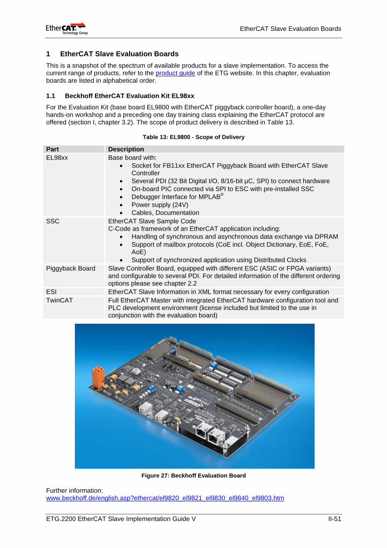
EtherCAT Slave Evaluation Boards
1 EtherCAT Slave Evaluation Boards This is a snapshot of the spectrum of available products for a slave implementation. To access the current range of products, refer to the product guide of the ETG website. In this chapter, evaluation boards are listed in alphabetical order.
1.1 Beckhoff EtherCAT Evaluation Kit EL98xx For the Evaluation Kit (base board EL9800 with EtherCAT piggyback controller board), a one-day hands-on workshop and a preceding one day training class explaining the EtherCAT protocol are offered (section I, chapter 3.2). The scope of product delivery is described in Table 13.
Table 13: EL9800 - Scope of Delivery
Figure 27: Beckhoff Evaluation Board
Further information: www.beckhoff.de/english.asp?ethercat/el9820_el9821_el9830_el9840_el9803.htm
Part Description EL98xx Base board with:
• Socket for FB11xx EtherCAT Piggyback Board with EtherCAT Slave Controller
• Several PDI (32 Bit Digital I/O, 8/16-bit µC, SPI) to connect hardware • On-board PIC connected via SPI to ESC with pre-installed SSC • Debugger Interface for MPLAB® • Power supply (24V) • Cables, Documentation
SSC EtherCAT Slave Sample Code C-Code as framework of an EtherCAT application including:
• Handling of synchronous and asynchronous data exchange via DPRAM • Support of mailbox protocols (CoE incl. Object Dictionary, EoE, FoE,
AoE) • Support of synchronized application using Distributed Clocks
Piggyback Board Slave Controller Board, equipped with different ESC (ASIC or FPGA variants) and configurable to several PDI. For detailed information of the different ordering options please see chapter 2.2
ESI EtherCAT Slave Information in XML format necessary for every configuration TwinCAT Full EtherCAT Master with integrated EtherCAT hardware configuration tool and
PLC development environment (license included but limited to the use in conjunction with the evaluation board)
ETG.2200 EtherCAT Slave Implementation Guide V II-51
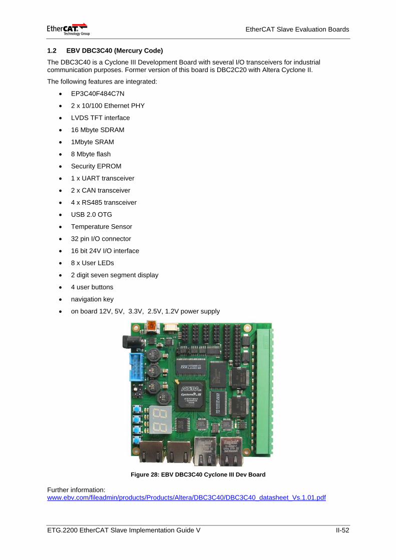
EtherCAT Slave Evaluation Boards
1.2 EBV DBC3C40 (Mercury Code)
The DBC3C40 is a Cyclone III Development Board with several I/O transceivers for industrial communication purposes. Former version of this board is DBC2C20 with Altera Cyclone II.
The following features are integrated:
• EP3C40F484C7N
• 2 x 10/100 Ethernet PHY
• LVDS TFT interface
• 16 Mbyte SDRAM
• 1Mbyte SRAM
• 8 Mbyte flash
• Security EPROM
• 1 x UART transceiver
• 2 x CAN transceiver
• 4 x RS485 transceiver
• USB 2.0 OTG
• Temperature Sensor
• 32 pin I/O connector
• 16 bit 24V I/O interface
• 8 x User LEDs
• 2 digit seven segment display
• 4 user buttons
• navigation key
• on board 12V, 5V, 3.3V, 2.5V, 1.2V power supply
Figure 28: EBV DBC3C40 Cyclone III Dev Board
Further information: www.ebv.com/fileadmin/products/Products/Altera/DBC3C40/DBC3C40_datasheet_Vs.1.01.pdf
ETG.2200 EtherCAT Slave Implementation Guide V II-52
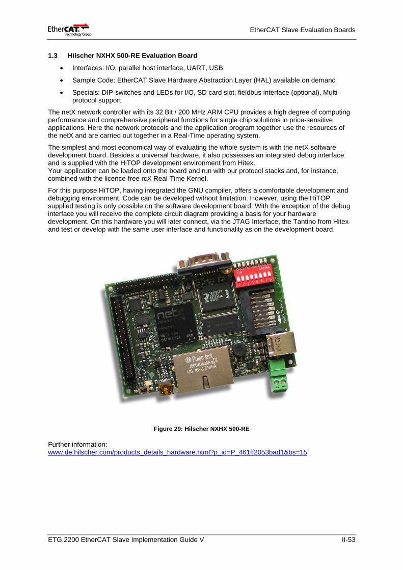
EtherCAT Slave Evaluation Boards
1.3 Hilscher NXHX 500-RE Evaluation Board
• Interfaces: I/O, parallel host interface, UART, USB
• Sample Code: EtherCAT Slave Hardware Abstraction Layer (HAL) available on demand
• Specials: DIP-switches and LEDs for I/O, SD card slot, fieldbus interface (optional), Multi-protocol support
The netX network controller with its 32 Bit / 200 MHz ARM CPU provides a high degree of computing performance and comprehensive peripheral functions for single chip solutions in price-sensitive applications. Here the network protocols and the application program together use the resources of the netX and are carried out together in a Real-Time operating system.
The simplest and most economical way of evaluating the whole system is with the netX software development board. Besides a universal hardware, it also possesses an integrated debug interface and is supplied with the HiTOP development environment from Hitex. Your application can be loaded onto the board and run with our protocol stacks and, for instance, combined with the licence-free rcX Real-Time Kernel.
For this purpose HiTOP, having integrated the GNU compiler, offers a comfortable development and debugging environment. Code can be developed without limitation. However, using the HiTOP supplied testing is only possible on the software development board. With the exception of the debug interface you will receive the complete circuit diagram providing a basis for your hardware development. On this hardware you will later connect, via the JTAG Interface, the Tantino from Hitex and test or develop with the same user interface and functionality as on the development board.
Figure 29: Hilscher NXHX 500-RE
Further information: www.de.hilscher.com/products_details_hardware.html?p_id=P_461ff2053bad1&bs=15
ETG.2200 EtherCAT Slave Implementation Guide V II-53
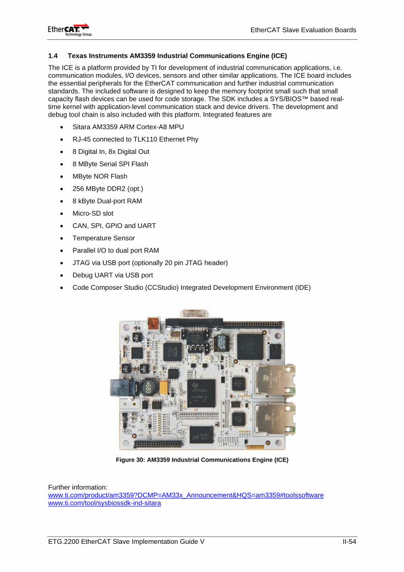
EtherCAT Slave Evaluation Boards
1.4 Texas Instruments AM3359 Industrial Communications Engine (ICE)
The ICE is a platform provided by TI for development of industrial communication applications, i.e. communication modules, I/O devices, sensors and other similar applications. The ICE board includes the essential peripherals for the EtherCAT communication and further industrial communication standards. The included software is designed to keep the memory footprint small such that small capacity flash devices can be used for code storage. The SDK includes a SYS/BIOS™ based real-time kernel with application-level communication stack and device drivers. The development and debug tool chain is also included with this platform. Integrated features are
• Sitara AM3359 ARM Cortex-A8 MPU
• RJ-45 connected to TLK110 Ethernet Phy
• 8 Digital In, 8x Digital Out
• 8 MByte Serial SPI Flash
• MByte NOR Flash
• 256 MByte DDR2 (opt.)
• 8 kByte Dual-port RAM
• Micro-SD slot
• CAN, SPI, GPIO and UART
• Temperature Sensor
• Parallel I/O to dual port RAM
• JTAG via USB port (optionally 20 pin JTAG header)
• Debug UART via USB port
• Code Composer Studio (CCStudio) Integrated Development Environment (IDE)
Figure 30: AM3359 Industrial Communications Engine (ICE)
Further information: www.ti.com/product/am3359?DCMP=AM33x_Announcement&HQS=am3359#toolssoftware www.ti.com/tool/sysbiossdk-ind-sitara
ETG.2200 EtherCAT Slave Implementation Guide V II-54

EtherCAT Slave Evaluation Boards
1.5 Texas Instruments AM3359 Industrial Development Kit (IDK)
The IDK from TI supports development of industrial communication applications, i.e. PLCs and motion control. The software supplied with the IDK includes TI’s SYS/BIOS™ real-time kernel, EtherCAT firmware and an evaluation version of EtherCAT application level sample stack. For motion-control applications, the IDK includes multiple pulse width modulation drivers and motor feedback hardware such as A/D converters. For motor control, a C2000™ Piccolo™ MCU and a Stellaris® ARM® MCU are integrated. Integrated features in more detail are:
• Sitara AM3359 ARM Cortex-A8 MPU
• TI Piccolo™ TMS320F28027 μC with integrated AD converters
• TI Stellaris® LM3S5R31 ARM Cortex-M3 μC
• 256 MByte NAND Flash
• 512 MByte DDR2
• SD/MMC slot
• 8 MByte SPI Flash
• PWM Controllers
• Digital inputs and outputs (I/O)
• 1 x 10/100 standard Ethernet port (TLK110 phy)
• x Real-time Ethernet ports (TLK110 phys)
• USB, CAN, SPI, I2C, UART, General purpose I/O
• 20 pin JTAG header
• Code Composer Studio (CCStudio) Integrated Development Environment (IDE)
Figure 31: AM3359 Industrial Development Kit (IDK)
Further information: www.ti.com/product/am3359?DCMP=AM33x_Announcement&HQS=am3359#toolssoftware
ETG.2200 EtherCAT Slave Implementation Guide V II-55
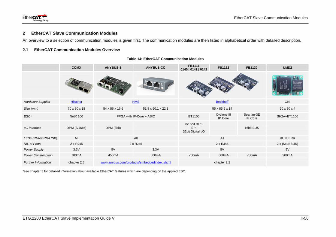
EtherCAT Slave Communication Modules
2 EtherCAT Slave Communication Modules An overview to a selection of communication modules is given first. The communication modules are then listed in alphabetical order with detailed description.
2.1 EtherCAT Communication Modules Overview
Table 14: EtherCAT Communication Modules
COMX ANYBUS-S ANYBUS-CC FB1111 0140 | 0141 | 0142 FB1122 FB1130 UMD2
Hardware Supplier Hilscher HMS Beckhoff OKI
Size (mm) 70 x 30 x 18 54 x 86 x 16,6 51,8 x 50,1 x 22,3 55 x 85,5 x 14 20 x 30 x 4
ESC* NetX 100 FPGA with IP-Core + ASIC ET1100 Cyclone III IP Core
Spartan-3E IP Core SH2A+ET1100
µC Interface DPM (8/16bit) DPM (8bit) 8/16bit BUS
SPI 32bit Digital I/O
16bit BUS
LEDs (RUN/ERR/LINK) All All All RUN, ERR
No. of Ports 2 x RJ45 2 x RJ45 2 x RJ45 2 x (MII/EBUS)
Power Supply 3.3V 5V 3.3V 5V 5V
Power Consumption 700mA 450mA 500mA 700mA 600mA 700mA 200mA
Further Information chapter 2.3 www.anybus.com/products/embeddedindex.shtml chapter 2.2
*see chapter 3 for detailed information about available EtherCAT features which are depending on the applied ESC.
ETG.2200 EtherCAT Slave Implementation Guide V II-56
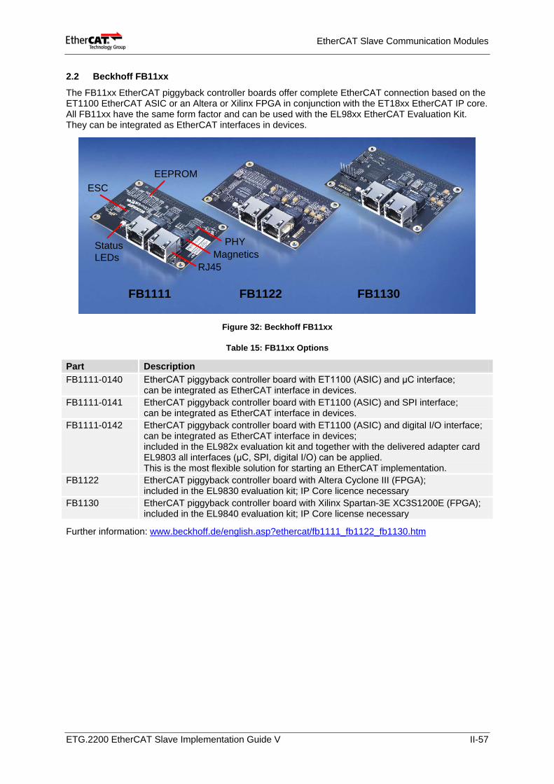
EtherCAT Slave Communication Modules
2.2 Beckhoff FB11xx
The FB11xx EtherCAT piggyback controller boards offer complete EtherCAT connection based on the ET1100 EtherCAT ASIC or an Altera or Xilinx FPGA in conjunction with the ET18xx EtherCAT IP core. All FB11xx have the same form factor and can be used with the EL98xx EtherCAT Evaluation Kit. They can be integrated as EtherCAT interfaces in devices.
FB1111 FB1122 FB1130
RJ45Magnetics
PHYStatusLEDs
ESCEEPROM
Figure 32: Beckhoff FB11xx
Table 15: FB11xx Options
Part Description FB1111-0140 EtherCAT piggyback controller board with ET1100 (ASIC) and μC interface;
can be integrated as EtherCAT interface in devices. FB1111-0141 EtherCAT piggyback controller board with ET1100 (ASIC) and SPI interface;
can be integrated as EtherCAT interface in devices. FB1111-0142 EtherCAT piggyback controller board with ET1100 (ASIC) and digital I/O interface;
can be integrated as EtherCAT interface in devices; included in the EL982x evaluation kit and together with the delivered adapter card EL9803 all interfaces (μC, SPI, digital I/O) can be applied. This is the most flexible solution for starting an EtherCAT implementation.
FB1122 EtherCAT piggyback controller board with Altera Cyclone III (FPGA); included in the EL9830 evaluation kit; IP Core licence necessary
FB1130 EtherCAT piggyback controller board with Xilinx Spartan-3E XC3S1200E (FPGA); included in the EL9840 evaluation kit; IP Core license necessary
Further information: www.beckhoff.de/english.asp?ethercat/fb1111_fb1122_fb1130.htm
ETG.2200 EtherCAT Slave Implementation Guide V II-57
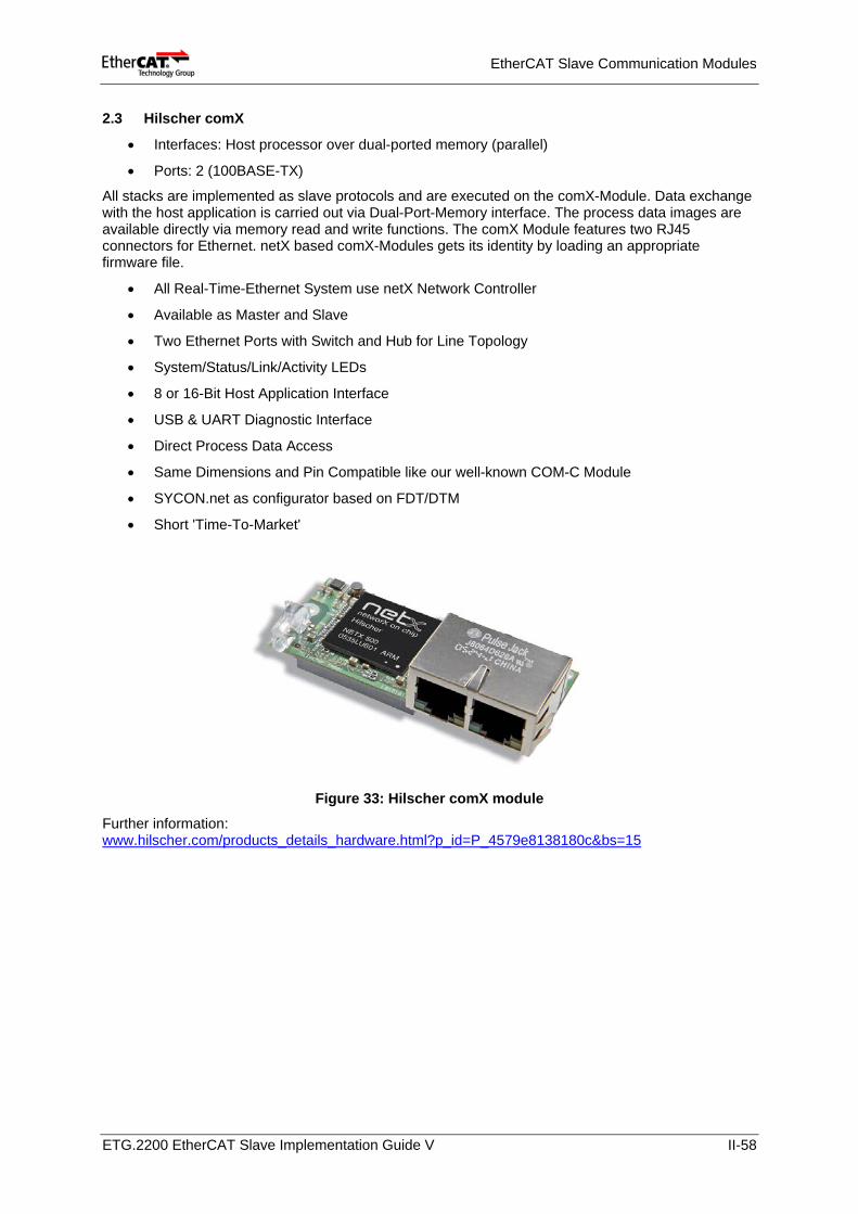
EtherCAT Slave Communication Modules
2.3 Hilscher comX
• Interfaces: Host processor over dual-ported memory (parallel)
• Ports: 2 (100BASE-TX)
All stacks are implemented as slave protocols and are executed on the comX-Module. Data exchange with the host application is carried out via Dual-Port-Memory interface. The process data images are available directly via memory read and write functions. The comX Module features two RJ45 connectors for Ethernet. netX based comX-Modules gets its identity by loading an appropriate firmware file.
• All Real-Time-Ethernet System use netX Network Controller
• Available as Master and Slave
• Two Ethernet Ports with Switch and Hub for Line Topology
• System/Status/Link/Activity LEDs
• 8 or 16-Bit Host Application Interface
• USB & UART Diagnostic Interface
• Direct Process Data Access
• Same Dimensions and Pin Compatible like our well-known COM-C Module
• SYCON.net as configurator based on FDT/DTM
• Short 'Time-To-Market'
Figure 33: Hilscher comX module
Further information: www.hilscher.com/products_details_hardware.html?p_id=P_4579e8138180c&bs=15
ETG.2200 EtherCAT Slave Implementation Guide V II-58
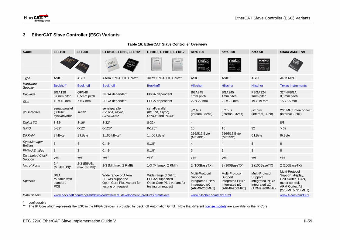
EtherCAT Slave Controller (ESC) Variants
3 EtherCAT Slave Controller (ESC) Variants
Table 16: EtherCAT Slave Controller Overview
Name ET1100 ET1200 ET1810, ET1811, ET1812 ET1815, ET1816, ET1817 netX 100 netX 500 netX 50 Sitara AM3357/9
Type ASIC ASIC Altera FPGA + IP Core** Xilinx FPGA + IP Core** ASIC ASIC ASIC ARM MPU
Hardware Supplier Beckhoff Beckhoff Beckhoff Beckhoff Hilscher Hilscher Hilscher Texas Instruments
Package BGA128 0,8mm pitch
QFN48 0,5mm pitch FPGA dependent FPGA dependent BGA345
1mm pitch BGA345 1mm pitch
PBGA324 1mm pitch
324NFBGA 0,8mm pitch
Size 10 x 10 mm 7 x 7 mm FPGA dependent FPGA dependent 22 x 22 mm 22 x 22 mm 19 x 19 mm 15 x 15 mm
µC Interface serial/parallel (8/16bit, sync/async)*
serial* serial/parallel (8/16bit, async) AVALON®*
serial/parallel (8/16bit, async) OPB®* and PLB®*
µC bus (internal, 32bit)
µC bus (internal, 32bit)
µC bus (internal, 32bit)
200 MHz interconnect (internal, 32bit)
Digital I/O 8-32* 8-16* 8-32* 8-32* - - - 8/8
GPIO 0-32* 0-12* 0-128* 0-128* 16 16 32 > 32
DPRAM 8 kByte 1 kByte 1...60 kByte* 1...60 kByte* 256/512 Byte (Mbx/PD)
256/512 Byte (Mbx/PD) 6 kByte 8kByte
SyncManager Entities 8 4 0…8* 0…8* 4 4 8 8
FMMU Entities 8 3 0…8* 0…8* 3 3 8 8 Distributed Clock Support yes yes yes* yes* yes yes yes yes
No. of Ports 2-4 (MII/EBUS)*
2-3 (EBUS, max. 1x MII)* 1-3 (MII/max. 2 RMII) 1-3 (MII/max. 2 RMII) 2 (100BaseTX) 2 (100BaseTX) 2 (100BaseTX) 2 (100BaseTX)
Specials
BGA routable with standard PCB
Wide range of Altera FPGAs supported Open Core Plus variant for testing on request
Wide range of Xilinx FPGAs supported Open Core Plus variant for testing on request
Multi-Protocol Support Integrated PHYs Integrated µC (ARM9-200MHz)
Multi-Protocol Support Integrated PHYs Integrated µC (ARM9-200MHz)
Multi-Protocol Support Integrated PHYs Integrated µC (ARM9-200MHz)
Multi-Protocol Support, display, Gbit Switch, CAN, motor control, ARM Cortex A8 (275 MHz-720 MHz)
Data Sheets www.beckhoff.com/english/download/ethercat_development_products.htm#slave www.hilscher.com/netx.html www.ti.com/am335x
* configurable ** The IP Core which represents the ESC in the FPGA devices is provided by Beckhoff Automation GmbH. Note that different license models are available for the IP Core.
ETG.2200 EtherCAT Slave Implementation Guide V II-59
Missing your device?
4 Missing your device? Section II generally contains a snapshot of the spectrum of available products for a slave implementation. ETG members that offer EtherCAT development products, EtherCAT implementation services and EtherCAT workshops are invited to contribute information to the ETG for this guide. A range of products can be found at www.ethercat.org/products.
If you are missing your device here, you found an error or you have a suggestion for slave implementation support, feel free to contact the ETG and help to improve this document.
ETG.2200 EtherCAT Slave Implementation Guide V II-60