applicability of chsst maglev technology for u.s. urban ... · applicability of chsst maglev...
TRANSCRIPT

U. S. Departmentof Transportation
Federal TransitAdministration
Applicability of CHSST MaglevTechnology for U.S. Urban Transportation
June 2003
Report Number FTA-MD-26-7029-2003.1

NOTICE
This document is disseminated under the sponsorship of the U.S.Department of Transportation in the interest of information exchange.The United States Government assumes no liability for its contents or usethereof.
The United States Government does not endorse products ofmanufacturers. Trade or manufacturer’s names appear herein solelybecause they are considered essential to the objective of this report.

i
REPORT DOCUMENTATION PAGE Form Approved
OMB No. 0704-0188
Public reporting burden for this collection of information is estimated to average 1 hour per response, including the time for reviewing instructions, searching existing data sources, gathering and maintaining the data needed,and completing and reviewing the collection of information. Send comments regarding this burden estimate or any other aspect of this collection of information, including suggestions for reducing this burden, to WashingtonHeadquarters Services, Directorate for Information Operations and Reports, 1215 Jefferson Davis Highway, Suite 1204, Arlington, VA 22202-4302, and to the Office of Management and Budget, Paperwork ReductionProject (0704-0188), Washington, DC 20503.
1. AGENCY USE ONLY (Leave blank)
Report Number FTA-MD-26-7029-2003.1
2. REPORT DATE
June 2003
3. REPORT TYPE AND DATES COVERED
Final Report
4. TITLE AND SUBTITLE
Applicability of CHSST Technology for U.S. Urban Transportation
5. FUNDING NUMBERS
6. AUTHOR(S)
G. Samavedam1, F. Raposa2, R. Feder3
7. PERFORMING ORGANIZATION NAME(S) AND ADDRESS(ES)
1Foster-Miller, Waltham, MA2FL Raposa Services, Cape Cod, MA3Port Authority of Allegheny County, PA
8. PERFORMING ORGANIZATION REPORT NUMBER
DSAI.020226
9. SPONSORING/MONITORING AGENCY NAME(S) AND ADDRESS(ES)
U.S. Department of TransportationFederal Transit AdministrationOffice of Technology400 Seventh Street, SWWashington, DC 20590
10. SPONSORING/MONITORING AGENCY REPORT NUMBER
11. SUPPLEMENTARY NOTES
COTR: Venkat Pindiprolu, FTA
12a. DISTRIBUTION/AVAILABILITY STATEMENT
Limited Distribution
12b. DISTRIBUTION CODE
N/A
13. ABSTRACT (Maximum 200 words)
This report discusses the Chubu HSST technology applicability to U.S. urban transportation. This low speed system based on the principle ofelectromagnetic levitation by attractive suspension and propulsion by vehicle mounted linear induction motors is being deployed in Japan. Thisreport was prepared based on the FTA team findings and experience with the system during a recent visit to Japan that observed the progress of thesystem deployment. The report discusses the performance characteristics of the CHSST vehicle and compares them with the FTA goals. For widerapplicability of the CHSST in the U.S., the report describes a higher speed vehicle design under consideration in Japan. U.S. mandatory requirementson the vehicle for use in the United States are also discussed.
A CHSST Maglev comparison with conventional Light Rail for urban transportation is presented. The report identifies two types of examplecorridors in the U.S. where there may be potential for application of the CHSST technology.
14. SUBJECT TERMS
Maglev, Magnetic Levitation, Propulsion, Urban, CHSST, Transportation
15. NUMBER OF PAGES
57
16. PRICE CODE
N/A
17. SECURITY CLASSIFICATION OF REPORT
Unclassified
18. SECURITY CLASSIFICATION OF THIS PAGE
Unclassified
19. SECURITY CLASSIFICATION OF ABSTRACT
Unclassified
20. LIMITATION OF ABSTRACT
NSN 7540-01-280-5500 Standard Form 298 (Rev. 2-89)Prescribed by ANSI Std. 239-18
298-102
ii
METRIC/ENGLISH CONVERSION FACTORS
ENGLISH TO METRIC METRIC TO ENGLISHLENGTH (APPROXIMATE) LENGTH (APPROXIMATE)
1 inch (in) = 2.5 centimeters (cm) 1 millimeter (mm) = 0.04 inch (in)
1 foot (ft) = 30 centimeters (cm) 1 centimeter (cm) = 0.4 inch (in)
1 yard (yd) = 0.9 meter (m) 1 meter (m) = 3.3 feet (ft)
1 mile (mi) = 1.6 kilometers (km) 1 meter (m) = 1.1 yards (yd)
1 kilometer (km) = 0.6 mile (mi)
AREA (APPROXIMATE) AREA (APPROXIMATE)
1 square inch (sq in, in2) = 6.5 square centimeters (cm2) 1 square centimeter (cm2) = 0.16 square inch (sq in, in2)
1 square foot (sq ft, ft2) = 0.09 square meter (m2) 1 square meter (m2) = 1.2 square yards (sq yd, yd2)
1 square yard (sq yd, yd2) = 0.8 square meter (m2) 1 square kilometer (km2) = 0.4 square mile (sq mi, mi2)
1 square mile (sq mi, mi2) = 2.6 square kilometers (km2) 10,000 square meters (m2) = 1 hectare (ha) = 2.5 acres
1 acre = 0.4 hectare (he) = 4,000 square meters (m2)
MASS - WEIGHT (APPROXIMATE) MASS - WEIGHT (APPROXIMATE)
1 ounce (oz) = 28 grams (gm) 1 gram (gm) = 0.036 ounce (oz)
1 pound (lb) = 0.45 kilogram (kg) 1 kilogram (kg) = 2.2 pounds (lb)
1 short ton = 2,000 pounds(lb)
= 0.9 tonne (t) 1 tonne (t) =
=
1,000 kilograms (kg)
1.1 short tons
VOLUME (APPROXIMATE) VOLUME (APPROXIMATE)
1 teaspoon (tsp) = 5 milliliters (ml) 1 milliliter (ml) = 0.03 fluid ounce (fl oz)
1 tablespoon (tbsp) = 15 milliliters (ml) 1 liter (l) = 2.1 pints (pt)
1 fluid ounce (fl oz) = 30 milliliters (ml) 1 liter (l) = 1.06 quarts (qt)
1 cup (c) = 0.24 liter (l) 1 liter (l) = 0.26 gallon (gal)
1 pint (pt) = 0.47 liter (l)
1 quart (qt) = 0.96 liter (l)
1 gallon (gal) = 3.8 liters (l)
1 cubic foot (cu ft, ft3) = 0.03 cubic meter (m3) 1 cubic meter (m3) = 36 cubic feet (cu ft, ft3)
1 cubic yard (cu yd, yd3) = 0.76 cubic meter (m3) 1 cubic meter (m3) = 1.3 cubic yards (cu yd, yd3)
TEMPERATURE (EXACT) TEMPERATURE (EXACT)
[(x-32)(5/9)] °F = y °C [(9/5) y + 32] °C = x °F
QUICK INCH - CENTIMETER LENGTH CONVERSION10 2 3 4 5
Inches
Centimeters 0 1 3 4 52 6 1110987 1312
QUICK FAHRENHEIT - CELSIUS TEMPERATURE CONVERSION -40° -22° -4° 14° 32° 50° 68° 86° 104° 122° 140° 158° 176° 194° 212°
°F
°C -40° -30° -20° -10° 0° 10° 20° 30° 40° 50° 60° 70° 80° 90° 100°
For more exact and or other conversion factors, see NIST Miscellaneous Publication 286, Units of Weightsand Measures. Price $2.50 SD Catalog No. C13 10286 Updated 6/17/98

iii
Table of Contents
Acknowledgments ...................................................................................................................vii
Executive Summary ..................................................................................................................1
1. Introduction............................................................................................................3
2. Technical Background ...........................................................................................52.1 HSST 100L Vehicle .................................................................................................52.2 HSST 200 Series Vehicle .........................................................................................82.3 Summary................................................................................................................20
3. Usability Assessment ............................................................................................213.1 Objectives ..............................................................................................................213.2 Assessment Method ...............................................................................................213.3 Observations and Remarks .....................................................................................213.4 Comparison with LRT............................................................................................223.5 Environmental Considerations................................................................................233.6 Deployment Issues .................................................................................................293.7 Summary................................................................................................................29
4. Deployment Progress of HSST ............................................................................314.1 Guideway Construction Progress............................................................................314.2 Vehicle and Manufacturing ....................................................................................334.3 Linear Induction Motor ..........................................................................................354.4 Financing and Costs of Deployment.......................................................................374.5 Summary................................................................................................................38
5. Applicability to U.S. Scenarios ............................................................................395.1 North Bethesda Transitway Corridor ......................................................................395.2 Colorado I-70 Maglev Project ................................................................................405.3 Summary................................................................................................................41
6. Conclusions and Recommendations ....................................................................436.1 Conclusions ...........................................................................................................436.2 Recommendations..................................................................................................43
7. References.............................................................................................................45
Appendix A. February 2003 Trip Agenda ............................................................................47

iv
List of Figures
Figure 1. CHSST Maglev Module and Rail Cross-Section .........................................................6Figure 2. End Door on 100L Vehicle..........................................................................................7Figure 3. CHSST 200 Prototype Vehicle..................................................................................10Figure 4. CHSST Hiroshima 200 km/h Vehicle........................................................................11Figure 5. 200P LIM Performance Design Sample.....................................................................12Figure 6. Drag Resistance Characteristics of the CHSST 200P Two Car Train .........................15Figure 7. CHSST 200P Maximum Thrust Capability Per Car ...................................................16Figure 8. CHSST 200P Acceleration Performance and Maximum Power Capability ................17Figure 9. Detailed Layout of Tobukyu HSST Line, Aichi Expo 2005.......................................31Figure 10. Columns Under Construction ..................................................................................32Figure 11. Maintenance Depot Under Construction..................................................................32Figure 12. Cross Section of Standard CHSST Single Guideway...............................................33Figure 13. Three Car Trainset ..................................................................................................34Figure 14. The LIM in Assembly at the ToyoDenki Plant in Yokohama...................................35Figure 15. The 100 Series LIM After the Varnishing Process...................................................36Figure 16. The 100 Series LIM After Painting and Attaching Connectors ................................36Figure 17. North Bethesda Corridor .........................................................................................39Figure 18. I-70 Mountain Alignment........................................................................................41

v
List of Tables
Table 1. HSST Development History .........................................................................................5Table 2. CHSST 100L Vehicle Performance versus FTA Goals .................................................8Table 3. Chubu Selected Data on Vehicle Upgrades for the Colorado Corridor Project ............19Table 4. FTA System Requirements for Propulsion Sensitive Parameters.................................19Table 5. Breakdown of Costs and Estimated Revenues.............................................................37Table 6. Financing Breakdown of Civil Work ..........................................................................37Table 7. Financing Breakdown of Systems Work.....................................................................37

vi
Acronyms
ADA Americans with Disabilities ActASTM American Society of Testing MaterialsATC Automated Train ControlATO Automated Train OperationsDLIT Department of Land, Infrastructure and TransportationEIS Environmental Impact StatementFTA Federal Transit AdministrationLIM Linear Induction MotorLRT Light Rail TransitMUSA Maglev Urban System AssociatesNFPA National Fire Protection AssociationTKL Tobu Kyuryo Line

vii
Acknowledgments
This work was performed under the overall technical and program direction of Mr. VenkatPindiprolu, who is the Contracting Officer’s Technical Representative (COTR) from the FederalTransit Administration. The authors are grateful to him for his inputs and arrangements for theexecution of the visit to CHSST and other facilities in Japan.
The authors are grateful to the Chubu HSST team, in particular Messrs. Masaaki Fujino, MichioTakahashi and Junro Kato who put in hours of work to respond to the FTA team’s questionsduring the visit to Japan.
The authors wish to thank Dr. John Harding of the Federal Railroad Administration for histechnical input and guidance during this project. The other members of the visiting teamprovided input to this work that was central to its completion.
Technical Team
• Dr. John Harding, FRA
• Dr. David Keever, SAIC
• Yoav Arkin, Earth Tech, MUSA Team
User Assessment Team
• Mr. Gary Erenrich, Montgomery County, Maryland
• Dr. David Munoz, consultant to the Colorado Intermountain Fixed Guideway Authority(CIFGA)
• Mr. Clark Roberts, Colorado Department of Transportation
• Mr. Suhair Alkhatib, Maryland Transit Administration
• Mr. Denis Cournoyer, Consultant, Hampton Roads Transit, Virginia
The funding for the work came from the FTA. Foster-Miller and FL Raposa Services aresubcontractors to the SAIC. Special thanks are due to Dr. David Keever of SAIC for his help inthe project management.


1
Executive Summary
The Federal Transit Administration (FTA) is examining the possibility of introducingmagnetically levitated low speed vehicles for urban transportation in the United States to reduceroad traffic congestion. For this purpose, the FTA is evaluating existing technologies and alsodeveloping alternate technologies within the realm of Maglev. One of the existing technologiescurrently under deployment is the Chubu HSST in Japan. To assess its technical merits andapplicability to U.S. scenarios, in February, 2003 the FTA sent a team of experts to Japan,including a select group of representatives from U.S. transit agencies.
This report is based on the FTA team visit to CHSST in the Nagoya facility where the Maglevvehicles are being tested on a special test track, and also to facilities elsewhere in Japan wherethe vehicles and linear motors are being manufactured. The visit involved discussions with theCHSST technical staff and representatives of Aichi Prefecture (similar to state government) inNagoya, Japan and the national Department of Land, Infrastructure, and Transportation (DLIT),which assisted in funding the project.
A previous delegation to Japan in 2002 focused on the HSST 100L Series vehicle and prepared areport that compared the HSST performance characteristics with FTA goals. A major conclusionof the report is that although the vehicle does not satisfy all the FTA goals, the vehicle andMaglev technology are applicable for certain scenarios in the U.S. For many other scenarios it isdesirable to upgrade the vehicle, particularly to achieve higher peak speeds (to 200 km/h fromthe existing 100km/h). The existing vehicle should also be examined and modified, if necessary,for improved egress, crashworthiness, fire safety, and ADA requirements, which are mandatoryin the U.S.
The focus of the recent visit was on the 200 km/h speed vehicles, for which the CHSST hasspecifications and preliminary design concepts. In addition, clarifications were sought on themandatory requirements referred to above. The vehicle and motor manufacturing infrastructurefor the CHSST was also examined. The current construction for a deployment on a 9 km track inNagoya, to be operational in 2005, was also monitored by the FTA team during the one weekstay in Japan.
The following conclusions are drawn in this report:
• The current CHSST Maglev technology has potential application in U.S. urbantransportation, particularly for short distance routes with close station spacings. For longdistance routes with long station spacings, the CHSST Maglev vehicle needs technicalenhancements requiring developmental work.
• The CHSST technology has been demonstrated and is mature, with the necessarymanufacturing support. It is in a state of readiness for deployment in the U.S. on shortstation spacing scenarios of less than two miles, typical of today’s urban application, forefficient trip times.
• The advantages of CHSST Maglev over traditional transit systems such as Light Rail includepublic acceptance due to low noise, low vibration, superior ride quality, superior gradeclimbing, and low energy consumption.

2
• The U.S. need to examine methods of cost reduction on the CHSST guideway for adoption inurban transportation scenarios, and may consider joint projects with CHSST for technologyimprovements and implementation in U.S. urban scenarios.

3
1. Introduction
The FTA sent a delegation to Japan in March 2002 to evaluate the Chubu HSST technology forpotential application to U.S. urban transportation. The evaluation is presented in a technicalreport [1] which covers the performance and operational characteristics of the CHSST, includingthe guideway system, vehicle system, levitation, guidance and propulsion systems, brakingsystem, automated train operations, and component and system level safety.
The costs as given by the CHSST are also presented in the report. The FTA team concluded thatthe CHSST system is a viable Maglev system for low speed urban transportation and hasadvantages such as grade negotiating capability, low noise and pollution.
The CHSST system design characteristics are compared with the FTA performancerequirements, (speed, acceleration, etc.), and with U.S. mandatory requirements such asemergency egress, crashworthiness, and those stipulated in the Americans with Disabilities Act(ADA).
The assessment of the CHSST for U.S. applications [1] showed that the CHSST does not satisfysome of the FTA goals, particularly for maximum speed, acceleration, deceleration, and gradeclimbing capability. Additionally, some of the U.S. mandatory requirements are also not fullysatisfied in the current design. These issues were communicated to the CHSST staff with theintent of obtaining their comments on enhancements to their system for potential use in theUnited States.
The FTA team made a follow-on trip to Japan in February, 2003, this time including severalexperienced managers from U.S. transit agencies. The names of the team members and the tripagenda are presented in Appendix A. The specific aims of this trip were:
• For the Transit User Group to experience the CHSST and assess its potential for U.S.transit use.
• To witness the CHSST deployment on Tobu Kyuryo Line (TKL) in Nagoya and to observein-progress guideway construction and vehicle fabrication.
• To obtain feedback from CHSST designers on previous FTA evaluations andrecommendations.
• To review technical data with CHSST on the 200 Series (120 mph) vehicle design underconsideration.
• To obtain input on CHSST costs if deployed in the U.S.
The purpose of this report is to present the findings of the team as a result of the visit. Section 2of the report presents further technical assessment of the Series 100L vehicle, which has amaximum speed of 100 km/h (60 mph) and is being deployed by the CHSST on a revenue line inNagoya. This assessment is made on the basis of the CHSST answers to the questions raised bythe FTA team [1]. Section 2 also contains an evaluation of the conceptual 200 Series vehicle,which has operational speed capability up to 200 km/h. The FTA is interested in this vehiclebecause it meets the maximum speed goal for U.S. urban Maglev transportation. The issuesaround upgrading the existing 100L vehicle to the 200 Series are also discussed in this section.

4
Section 3 presents an assessment of the usability of the CHSST Maglev system in the U.S. andidentifies issues and comparison with conventional systems such as LRT. The issues coverenvironmental and deployment aspects of Maglev.
Section 4 describes the deployment progress made in Japan on the 9.2 km Tobu Kyuryo Line inNagoya. Construction progress on the infrastructure (guideway, pylons, and foundation) andvehicle manufacturing progress are presented. Cost and financing issues are also covered in thissection.
In Section 5, the applicability of the CHSST to U.S. urban transportation is discussed usingexample scenarios.
Conclusions of practical interest, with recommendations, are presented in Section 6.

5
2. Technical Background
The assessment of Chubu HSST was performed by the FTA team which visited Japan in March2002 and February 2003. During these visits, the team collected HSST performance and safetytest data which was compared against the FTA system requirements. From the 2002 visit, atechnical report [1] was prepared to identify the design changes needed to the 100 series vehicleto satisfy the FTA requirements and also U.S. mandatory requirements for consideration ofpotential deployment of the CHSST technology in U.S. urban areas. The technical backgroundof the 100L vehicle, the desired improvements, and the status of the 200 Series vehicles arepresented in the following sections.
2.1 HSST 100L Vehicle
The HSST vehicles have had significant development history as shown in Table 1. The 100Lseries vehicle testing started in 1995 to support deployment on the Tobu Kyuryo Line in Nagoya,which is discussed later in this report.
Table 1. HSST Development History
Date Development1972 Studies for High Speed Access to Airports (Japan Air
Lines)1975-1981 Kawasaki 1.3/1.6 km Test Track
• HSST-01 Subscale Vehicle -- 307km/h• HSST-02 Full Scale Vehicle
1985-1989 HSST-03, -04, -05 Vehicles• Low speed demonstrations at several expositions
1991-Present Nagoya 1.6 km Test Track• 100-S (8 m “short”) Vehicles in 2-car consist
1991-1993 Aichi Prefecture/Ministry of Transport Evaluation ofHSST Maglev for Commercial Suitability
1995 Testing of 100-L (14 m “long”) cars1995-2003 Testing to support development of Tobu Kyuryo
system and vehicles (based on 100-L)2003 Start construction of 9.2 km Tobu Kyuryo (Tobukyu)
Line in Aichi Prefecture2005 Commercial Operation of Tobukyu Line at Aichi
Exposition
The 100L vehicle carbody, which is about 14 m long, is of aluminum alloy. Levitation andguidance are from Electromagnetic Suspension (EMS). The propulsion is derived from thereaction force of the aluminum plate on the guideway to the electromagnetic force generated byan onboard Linear Induction Motor (LIM). The aluminum reaction plate is attached to acontinuous steel rail mounted on steel sleepers, which are supported on hollow rectangularconcrete girders as shown in Figure 1. The vehicle electromagnets are attracted to the steel railwhen energized, and the gap (typically 8 mm) is continuously monitored by sensors to controlthe current in the vehicle magnet coils.

6
Figure 1. CHSST Maglev Module and Rail Cross-Section
There are five modules on each side of the vehicle. Each module can be independentlyarticulated as indicated by its connection with the “slide tables” between the carbody andmodules. There is one motor in each of the modules, totaling 10 motors per vehicle. The single-sided motor makes use of an aluminum winding for light weight and economy.
The primary brakes are electrical. The secondary are hydraulically controlled caliper brakes.Automated Train Control (ATC) and Automated Train Operations (ATO) are to be deployed inrevenue service.
2.1.1 Technical Attributes Identified from the Assessment
The technology is mature, with significant research and development since 1972. The noise andvibration levels are very low so the vehicle is likely to receive public acceptance. The vehiclehas superior grade climbing capability when compared to LRT. The system is suitable for urbanarea applications on routes with close station spacings typical for today’s urban applications.
2.1.2 Mandatory Design Changes for U.S. Requirements
For applications in the U.S., the CHSST Maglev should satisfy the mandatory requirementsdescribed below.
ADA Requirements
The 100L vehicle needs to be modified by a) increasing the width of the side door openings from80 cm to 81.5 cm, b) increasing the width of the aisle between seats, stanchions and handrails on

7
the vehicle from 60 cm to 82 cm, and c) providing door chimes/buzzers for visually impairedpeople. These are discussed in the final report by MUSA [2].
This proposed approach to satisfy the ADA requirements reduces the seating capacity of thevehicle, requires significant body structural changes, and adds to the cost of the 100L vehicle.
Emergency Evacuation
The procedure being considered in Japan consists of opening the end doors on the end cars of thetrain and deploying a plank on the sleeper surfaces, from where the passengers can use a ladderto climb down one by one. Figure 2 shows the end doors on the vehicle for egress.
This procedure may not be rapid enough in an emergency with fire and smoke. Eliminatingsleepers by directly fastening the steel rail to the guideway girder may provide a surface forpassengers to distance themselves from the cars in a timely manner during an emergency, butthis is not considered in the existing CHSST guideway design.
Figure 2. End Door on 100L Vehicle
Crashworthiness
Sufficient vehicle crashworthiness is necessary to reduce injuries to passengers in collisions withother vehicles or objects on the guideway. The MUSA report [2] dismisses this issue, statingthat collisions are not possible because of the Automated Train Operation. However, collisionsmay occur because of objects (trees, rocks thrown by vandals) falling onto the guideway. Slowspeed collisions can take place in yards and maintenance depots.
The only response received from the CHSST is that the 100L vehicle body is designed towithstand a buff load of 34 tons. It is clear that this issue needs further evaluation for theusability of the system in the U.S.

8
2.1.3 Desirable Changes to Meet FTA Performance Goals
Some changes in the vehicle are desirable for wider applicability to U.S. scenarios. At presentthe CHSST 100L vehicle does not satisfy the FTA performance goals. Current 100Lperformance is contrasted with the FTA goals in Table 2. The significant differences in theCHSST performance and the FTA goals are in the speed, emergency deceleration, and minimumhorizontal turning radius. The most important of these is probably the maximum speed. The160 km/h speed cannot be achieved by the current 100L design, which according to HSST staffis designed for and can be operated at 130 km/h. There is still a need for a higher speed vehicleas discussed in the following subsection.
Table 2. CHSST 100L Vehicle Performance versus FTA Goals
CHSST Performance FTA Goals*
Maximum Speed: 100 km/h (60 mph) 160 km/h (100 mph)
Maximum Acceleration: 0.11 g (2.5 mph/s) 0.15 g (3.4 mph/s)
Maximum Deceleration: 0.11 g (2.5 mph/s) 0.15 g (3.4 mph/s)
Emergency Deceleration: 0.13 g (2.8 mph/s) 0.15 g (5.4 mph/s)
Minimum Curve Radius: Horizontal Vertical
50 m (250 ft)1500 m (6000 ft)
18.3 m (60 ft)1500 m (6000 ft)
Grade Climbing Capability: 7 percent (reduced speed) 7 percent (full speedcapability)
*Note: These goals are tentative and are being finalized by the FTA
The FTA requirement for vehicle maximum speed is 160 km/h (Table 2). The increased speedwill reduce trip time over long distances with stations spaced far apart (> 2 miles). Increasedacceleration capability will reduce trip time over short distances with close station spacings(< 2 miles). The difference between FTA goals and the 100L acceleration/decelerationcapabilities typically reduce trip times by about 13 percent. To achieve increased speed,increased acceleration, and improved grade climbing capability, the 100L motor needs to bemore powerful, or a larger number of motors per vehicle will be required. A reduction in vehicleweight will also contribute to increased vehicle performance.
The HSST recommends the 200 Series vehicle for improved performance. The 200 Seriesvehicle, as described in the following subsection, is only in the conceptual design stage at thistime.
2.2 HSST 200 Series Vehicle
The HSST 200 series vehicle was originally developed in 1975 and was designated as theHSST-05. In the development history of the CHSST, this was the first modular design evolutionof HSST and unlike its predecessors incorporated both LIM propulsion and EMS levitation. Itwas also the first magnetically levitated train to be authorized to carry passengers, and it did so atthe Yokohama Exposition in 1989.

9
Although the LIM for the HSST-05 (see Table 1) was originally designed to operate at 200 km/h,the Yokohama exposition consisted of only a 570 m track which thus limited vehicle speeds to42 km/h. Because of this known limitation, Chubu has stated that the onboard power electronicscontrols for the LIM were not designed for the maximum speed capability, but designedspecifically for the Yokohama demonstration. Further, there were some propulsion designconfiguration issues on how the 3.6 m LIM modules were to be connected in order to achieve anoptimum design and as of the time period of 1989 were still to be resolved.
Following the Yokohama testing, Chubu planned to take an upgraded version of this vehicle toLas Vegas and test it to 200 km/h. However, the Las Vegas program did not materialize andhigh-speed testing was not performed. In the early 1990s, Chubu studied a 50 km route betweenHiroshima airport and downtown Hiroshima that would require a speed capability of up to200 km/h. Because of a downturn in the Japanese economy, the Hiroshima line was neverrealized.
Upon conclusion of the Yokohama testing, the high speed capability of the HSST-05 wasunproven and remains so at the present time. Testing on a laboratory-scaled wheel with a fullscale LIM module, however, had been successfully accomplished during its early developmenthistory. As such, the present version of the HSST 200 must be considered as a design conceptand for purposes of this report we will designate it as the HSST 200P (prototype) vehicle.
2.2.1 Current Development Status
1. Vehicle Configuration
The following information is based on data provided by Chubu and appears to be derived fromthe HSST-05 vehicle. Figure 3 shows a conceptual view of a two vehicle consist HSST 200P.Each section is 18.25 m long, 3.6 m high and 3.0 m wide. The seating arrangement shown of80 seats per section would appear to be representative of high-density seating. The track gauge,from LIM center to LIM center, is 2.0 m wide. For comparison, the track gauge for the100 series and TKL vehicles is 1.7 m. Chubu has stated two reasons for this difference. Onereason is to add some lateral stability with the wider gauge. The other equally important reasonis to provide the needed increased space for equipment installation between modules, principallyfor the higher powered inverter required for the 200-km/h speed capability. For comparison,Figure 4 shows a comparable view of the HSST-Hiroshima concept vehicle which was based onthe Yokohama HSST-05.

10
Figure 3. CHSST 200 Prototype Vehicle

11
Figure 4. CHSST Hiroshima 200 km/h Vehicle

12
One of the salient differences between the two concept vehicles is the more aerodynamicallyshaped nose of the 200P. As seen in Figure 3, another apparent difference is the lack ofdefinition of the modules for the 200P. The Hiroshima concept apparently was based on the useof five modules per side, similarly to the 100L vehicle resulting, in a LIM configuration of fivemodules in series and two sets in parallel (5s-2p). As stated by Chubu for the 200P, one of thedesign configurations requiring further definition is the series parallel configurations of themodules. Chubu stated that they will need to investigate the optimum series-parallel LIMconfiguration further. They stated that this could vary from the standard 5s-2p configuration to a2s-5p, and possibly to a lesser number of LIM powered modules such as the 3s-2p configuration.The User Group was provided performance characteristics for the 3s-2p configuration and thiswill be discussed in another section of the report.
At this time, the number of levitation magnets—two per module with ten modules—is thought tobe the same as the 100L. This may be subject to change as the final weight of the 200P becomesbetter defined and the LIM configuration is chosen. The weight goal for the 200P is similar tothe 100L at approximately 28 tonnes. Pending a more complete definition of the powerelectronics, the ultimate passenger payload weight is yet to be determined.
Estimated Performance
LIM performance sample design data for a four car train was provided by Chubu and is shown inFigure 5. These curves, which were developed on a per car basis, show the estimated vehicledrag resistance for both a zero and six percent gradient for a 33 tonne car. The data shown is forthe two-series three-parallel (2s-3p) LIM configuration. Also shown in Figure 5 are the thrustcapability and corresponding electrical characteristics of the LIM. The electrical characteristicsare LIM current, inverter output voltage (voltage per LIM pair), and DC input current. The DCinput conditions are for a 1500 VDC power supply.
Figure 5. 200P LIM Performance Design Sample

13
From a cursory review of the zero gradient drag resistance curve, it was found that the estimatedaggregate drag of the 200P vehicle closely follows that for the 100S vehicle as reported in ourJuly 2002 CHSST assessment report [1]. This was based on the reported Chubu 1993 testresults. Accordingly, the drag component equations developed by Chubu for the two car 100Sconfiguration can be used to approximate the drag components for the 200P when appropriatelyadjusted for the 200P configuration. The drag resistance components, in SI units (force inNewtons (N), speed in m/s and weight in kg), as reported in the July 2002 CHSST assessmentreport are:
Dc = 41.68*n N (1)
Dm1 = 3.354* V*(n*W) N V <5.56 m/s (2)
Dm2 = (18.221+0.0741* V)( n *W) N V ≥5.56 m/s (3)
Da=(1.6522+0.572*n) V2 N (4)
In these equations, Dc is the power collector drag, Dm is the magnetic drag, which has two partsdepending on speed, and Da is the aerodynamic drag. The term W represents the weight (mass)of a single car in kg and n represents the number of cars in a train.
For purposes of any analysis in this report the following are the assumed pertinentcharacteristics:
Vehicle Weight (Mass) Cross Section
100S 16,000 kg 8.58 m2
100L 26,000 8.32
200P 33,000 8.26
Also, unless otherwise specified, it will be assumed that a two vehicle consist will be analyzed(that is n=2).
The weights given above are used here because these are the weights specified for Chubusupplied data and do not necessarily reflect maximum capable weights. For example, the 100Lspecifications provided list 28,000 kg as the maximum capable weight for that sized vehicle.Further, unless the levitation system for the 200P concept is upgraded, the likely maximumweight for that vehicle will also be limited to about 28,000 kg.
Using Equations (1) through (4), the estimated drag resistance components and aggregate dragfor a 200P two-car train is shown in Figure 6. The magnetic drag equations have been furtheradjusted to reflect the planned increase in air gap from a nominal size of 8 mm to 9 mm. Asseen, the aerodynamic drag is the dominant component and peaks to nearly 9 kN at a speed of 56m/s (202 km/h). At this speed the output mechanical power requirement is nearly 600 kW.Using the equations, the calculated total thrust value is about three percent more than the valueshown in Figure 3 and probably reflects a slightly pessimistic value for the aerodynamic dragcomponent. Note that these equations were derived from the 100S vehicle tests, and the 200series vehicle should be more aerodynamically shaped. Of the nearly 600 kW of output power,about 16 percent is required to satisfy the magnetic drag component.
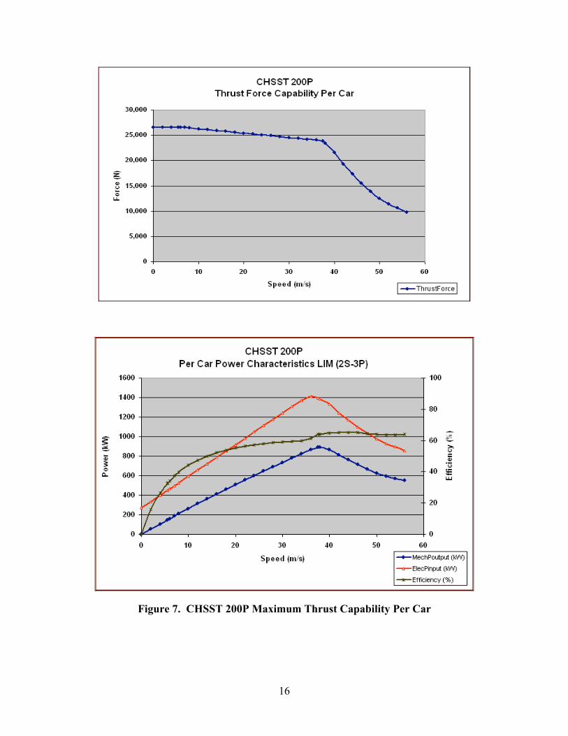
Figure 7 shows the maximum thrust capability and corresponding LIM power characteristics ona per car basis. The data shown here was derived directly from the Chubu data shown in Figure

14
5. A single car develops a maximum thrust of about 26.5 kN and maintains a nearly constantthrust out to about eight m/s (29 km/h). From this point on the thrust begins to decay slightly,and at the 38 m/s corner point the available thrust is 23.4 kN. At near the 56 m/s (202 km/h)point, about 10 kN of available thrust remains.
The lower chart in Figure 7, derived from the Chubu data in Figure 5, portrays both themechanical output power and corresponding electrical input power. From this data one canestimate the overall efficiency, which is also shown. The overall efficiency peaks at about65 percent in the speed range of 40-48 m/s, and is still above 64 percent at the maximum speedpoint of 56 m/s. Note that these are maximum capability estimates and would be expected to beless for cruise speed conditions. Note also, that the power characteristics of the 200P vehicle aresimilar in shape to the characteristics reported for the 100L in the July 2002 report [1], where thepeak power occurs at the speed point associated with the end of the maximum thrust profile andthen falls off for higher speeds.
The acceleration performance and maximum power characteristics for the CHSST 200P two cartrain are shown in Figure 8. The data shown are for zero gradient and zero headwind conditions.The maximum acceleration is about 0.08g and occurs over the speed range from zero to about16 m/s (58 km/h). For higher speeds, the acceleration drops off and finally gets to a point near56 m/s where there is no residual acceleration available. The plot shown here is for a slightlypessimistic aerodynamic drag resistance condition and may not be fully representative of anaerodynamically shaped 200P vehicle.
The bottom curve in Figure 8 shows the electrical power characteristics (in kVA) from the outputof the inverter to the mechanical output power of the vehicle. From these two points the powerfactor of the LIM can be estimated as shown. The power factor peaks at about 64 percent(0.64 pu) at 40 m/s (144 km/h), which is also the peak power point for the propulsion system.The power factor then falls off to about 53 percent at the end of the acceleration profile. Asexpected for cruise speed conditions, the power factor would be less than that shown formaximum capability performance.

15
Figure 6. Drag Resistance Characteristics of the CHSST 200P Two Car Train
16
Figure 7. CHSST 200P Maximum Thrust Capability Per Car

17
Figure 8. CHSST 200P Acceleration Performance and Maximum Power Capability

18
2.2.2 Preliminary Specifications for the Colorado Corridor Project
The Colorado Corridor project has a requirement for sustained operations at a minimum speed of160 km/h. The current version of the CHSST 100 series as applied in the TKL design has aspeed capability of 100 km/h with the possibility that with minor modifications its maximumspeed could be extended to 130 km/h. For the Colorado application, Chubu has stated that it willbe considering two approaches for meeting the desired performance of achieving 160-200 km/hoperation.
One approach for higher speed capability is to extend the performance of the 1700 mm gauge100-series type vehicle. The existing TKL vehicle would need to be increased in length fromapproximately 14 m to about 16 m, have a reduced height of less than 3 m and be moreaerodynamically shaped. It would need a corresponding weight increase from about 17 metrictonnes per car to about 18 tonnes. Seating capacity, depending upon whether the car is anend-car or mid-car configuration, would be about 79 to 88 seats. The propulsion-levitationmodules would need to be expanded from the current 2.5 m length, 10 modules per carconfiguration, to an estimated 3.4 m module length to accommodate a 2.5 m long higher-speedLIM design. Because of car length constraints, the number of modules per car would need to bereduced from 10 to 8 modules.
The alternate approach being considered is to modify the design of the 2000 mm gaugeYokohama 200P type vehicle. Such a vehicle would have a car length of 18 to 20 m or possiblymore, have an estimated weight of about 24 tonnes for both end and mid cars, and improve itsaerodynamic shape. The seating capacity per car, depending upon the car configuration, wouldvary from about 108 to 119 seats. The propulsion-levitation modules also would be about 3.4 min length to accommodate the 2.5-m LIMs and would use a 10 module per car configuration.The levitation magnet design would need to be modified to accommodate a 33 tonne/car designcriteria as compared to the 26 tonne/car design of the current 100 series vehicles.
As previously discussed, acceleration performance would be slightly reduced from the present4.0 km/h/s performance of the 100 series down to about 3.8 km/h/s. The longer modules arealmost certain to have an impact on vehicle performance on curves. Low speed turn out curveswould likely have to increase from the present 50 m design of the 100 series to 100 m or morefor the longer modules. Chubu has stated that main-line high speed curving performance both inthe horizontal and vertical directions would also need to be determined.
Table 3 contains selected data provided by Chubu on these concepts. The data shown hereshould be considered as preliminary and tentative only, as the design definition effort for thiscorridor is in its early stages of development.
At this time, it would appear that the preferred configuration for the Colorado Corridor is anextension of the 200P series.

19
Table 3. Chubu Selected Data on Vehicle Upgrades for the Colorado Corridor Project
100L(TKL)
Extended 100Series
Modified 200PSeries
Maximum Speed (km/h) 100 200 200Gauge (mm) 1700 1700 2000Vehicle Capacity (Seated)
End Car 81 79 108Mid Car 82 88 119
Car Length (m)End Car 14.0 16.2 19.6Mid Car 13.5 14.8 18.2
Empty Car Weight (tonne)End Car 17.1 18.0 24.0Mid Car 16.6 24.0
LIM (motor length, m) 1.8 2.5 2.5Levitation Design Criteria(tonne/car)
26 26 33
Guideway Horizontal RadiusSide Track (low speed) 50 110 100Main Line (line speed) 100 TBD TBD
2.2.3 Compliance With FTA Performance Requirements
As stated above, the 200P is a conceptual design whose design performance has not yet beenfully defined or specified. Therefore, a full description of the 200P system in the context of FTArequirements cannot be provided. Some of the key attributes of estimated propulsion systemperformance are known and enable a brief comparison to other CHSST systems. Table 4summarizes these attributes for two vehicle trains and compares them to what is known of the100L two vehicle train.
Table 4. FTA System Requirements for Propulsion Sensitive Parameters
Parameter FTA Requirement CHSST 200P CHSST 100LMaximum Speed 160km/h 200km/h 100km/hLongitudinal Acceleration 0.16 g 0.08 g 0.11 gLongitudinal Jerk 0.10 g/s TBD 0.08 g/sGrade Climbing 7% Full Performance
10% Degraded Performance7% @ 86km/h8% Creeping
7% @ 56km/h10% @ 44km/h
Horizontal Curves 18.3 m 100 m 50 mVertical Curves 1000 m TBD 1500 mHeadwind 50km/h Full Performance
80km/h Ride Comfort ThresholdTBD 90km/h
As seen from the table, at this point in the definition of the 200P vehicle only its maximum speedcapability of 200km/h meets or exceeds the FTA desired performance requirement. The TBDs

20
listed are To Be Determined data. All other data should be considered as provisional pending amore complete definition of the 200P vehicle.
With respect to the CHSST 100L, the longitudinal acceleration capability of the 200P is only0.08 g compared to 0.11 g for the 100L vehicle, both of which are well below the FTA desiredperformance goal of 0.16 g. Note that according to the maximum thrust data for both vehiclespublished here as well as in the previous assessment [1], the regime for constant acceleration forthe 200P vehicle is from zero speed to about 30km/h, compared to zero speed to about 46km/hfor the 100L vehicle. Hence, for the same vehicle weight, the 100L would have superioracceleration performance in the low speed operating regime and potentially shorter trip times forshort station-to-station distances.
Although neither vehicle will meet the FTA requirement of full performance on grades of up toand including the seven percent gradient, the 200P vehicle has a higher balance speed (steady-state speed) of 86km/h compared to a balance speed of about 56km/h for the 100L on thatparticular gradient. However, the 100L could be expected to negotiate ten percent grades atspeeds of up to 44 km/h (with no headwind) whereas the 200P, with its significantly reducedacceleration capability, could operate only at creeping speeds.
A 200P vehicle with its weight limited to 28,000 kg would have improved grade climbingcapability. With the seven percent gradient and 50 km/h headwind condition, the balanced speedincreases to about 136km/h with the reduced weight. However, the system could not operate atany creeping speeds on the ten percent gradient because the initial acceleration is still notadequate. Improving the initial acceleration is also necessary in order to meet that FTA goal.
As seen in this brief discussion, in addition to known needed improvements, the 200P requires amore comprehensive definition than what is currently known. Therefore, at this time it is notpossible to evaluate the degree of compliance of this conceptual vehicle with the whole spectrumof FTA requirements.
2.3 Summary
The 100L vehicle with a maximum operational speed of 100 km/h is suitable for routes withshort station spacings. The vehicle needs modifications in order to satisfy U.S. mandatoryrequirements. The modifications have been addressed to a certain extent, and need to be furtherexamined prior to 100L introduction on short routes in the U.S. For long routes, the vehicleperformance characteristics should be improved to reduce trip times. The CHSST hasconceptual designs with preliminary specifications for a vehicle that can be operated at a peakspeed of 200 km/h. Further examination of such higher speed vehicle designs will be requiredfor potential application in the U.S.

21
3. Usability Assessment
3.1 Objectives
As stated in Section 1, the CHSST assessment was performed by a selected group of specialistsfrom transit operations in the U.S. The overall objectives of this assessment are:
• Acquire first hand experience and knowledge of a running low speed Maglev system,
• Assess the applicability of the CHSST for U.S. urban transit needs, and
• Make recommendations on deployability and U.S. acceptance of the technology for urbantransit.
3.2 Assessment Method
The group performed a review of the existing materials including the first report [1] prepared bythe FTA team. A set of pre-trip questions for the CHSST was prepared to facilitate thediscussions with CHSST staff in Japan. Discussions and briefings with CHSST staff were heldto understand the operational and deployability issues. The FTA team took rides on the new100L three vehicle consist at the test track in Nagoya. Ride quality, ability of the vehicle tonegotiate curves and seven percent gradients, and wayside noise were subjectively evaluated bythe User Group. The User Group took a tour along the TKL Maglev guideway now underconstruction, and had discussions with the prefecture (state government) officials and plannerson cost and environmental issues.
In addition to the foregoing, the User Group made the following stops during the CHSSTevaluation:
• Visited the Maglev vehicle manufacturer, Nippon Sharyo.
• Visited the Linear Motor manufacturer, ToyoDenki.
• Rode in a Linear Rail Car in the Tokyo Metro.
• Met with Macquarie, a financing organization, for discussions on financing Maglev vehicles,etc.
• Met with the staff of the Department of Land, Infrastructure, and Transportation fordiscussions on safety issues, safety certification, and project financing by the JapaneseFederal Government.
3.3 Observations and Remarks
• The Chubu HSST has more than two decades of developmental and testing activitiesincluding demonstrations at several exhibitions with over 60,000 vehicle miles of experience.The most remarkable aspect of this is that no accidents or loss of levitation occurred at thesedemonstrations, showing the reliability of the CHSST vehicles.
• The vehicle ride was very comfortable with low noise and vibration. The vehicle wascapable of stopping and starting on a seven percent grade. Wayside observations by the

22
group showed that the vehicle produced very low noise at full vehicle speed (60 mph)running at grade as compared to nearby automobiles and trucks.
• The TKL route and construction site was visited by the group. The TKL is a 5.6 mile doubletrack, mostly elevated line, that includes about a one mile tunnel. It is expected to provide arevenue based service in eastern Nagoya, Japan, that is scheduled for operation in March2005. There will be nine stations. The train headway is to be 6-10 minutes, with expectedridership of 31,000 passengers per day. The construction operations through the city centerare being performed as planned. The construction requires large columns (6 ft diameter) anddeep foundations (> 60 ft) due to the potential for seismic activity.
• Public acceptance for Maglev seems to be based on:
- Low noise and vibration,
- Traffic free operation,
- No apparent electric or magnetic field problems,
- Good ride quality, and
- Minimal concern about visual impact of the elevated construction.
• The cost of construction as presented by the Japanese is high. The construction cost for theU.S. needs to be worked out. The guideway design appears to be very conservative, whichmay be required for seismic conditions in Japan.
• The maximum speed of 60 mph may be adequate for short station spacings. This will needenhancement to 100 mph for applications with longer station spacings (> 2 miles). Theacceleration/deceleration levels of .11g may contribute to higher trip time, as compared toFTA desirable acceleration of .16g.
3.4 Comparison with LRT
3.4.1 CHSST Advantages over LRT
The following are identified as the advantages of Maglev over the LRT.
• Low noise and vibration
• Grade climbing capability (sustained headway 7 percent grade, no headwind vs. 3-5 percentfor LRT)
• Smaller car width requiring narrower tunnels and guideways
• Low maintenance and operation costs
• Increased public acceptance
• Higher speeds due to grade separation, leading to higher ridership
3.4.2 CHSST Disadvantages Compared to LRT
The following are considered to be potential disadvantages of CHSST compared with LRT.

23
• Stringent guideway tolerances
• Lower acceleration/deceleration and speed capabilities requiring longer trip times (~ 13%more for short station spacings)
• Probable high initial cost
• No prior experience in the U.S.
• Requires smaller headways to meet capacity
• Visual impacts; inability to provide integrated at-grade operation
3.5 Environmental Considerations
Maglev is generally an elevated system. Any sections that would be at grade would be fencedoff, similar to the way an interstate highway would be separated from cross traffic. Operation ofMaglev would benefit from the grade separation, as there is no cross traffic or traffic signals,thus improving the speed of operation. Capital costs per mile would be more expensive due tothe elevated aspect, but being elevated would contribute to lowering annual operating costs dueto the higher speed of operation. Station spacing would likely be in the higher range of typical _-1 mile spacing, which contributes to its higher average operating speed and resulting in loweroperating and maintenance costs. With stations elevated and not in easy view of the street, therewould be additional security costs for the stations that would partially offset the lower operatingand maintenance costs.
Light Rail Transit could be completely grade separated like Maglev, but is generally not entirelygrade separated. There would likely be a mix of alignment, for example, 25 percent elevated,65 percent at grade on its own right-of-way (with traffic signals at cross streets), and ten percentin street. As a result of doing some portions at grade and in street rather than elevated, capitalcosts would be less but operating speeds would be lower and operating costs would increase.Station spacing is on the order of _ mile, thus contributing to lower operating speeds and higheroperating costs.
There are 20 environmental areas that are reviewed in a typical EIS, and by which various transitalternatives are compared and assessed. The following identifies the 20 areas, describes them,and reviews the two modal alternatives, Maglev and LRT, from the perspective of these areas.Where appropriate, the discussion suggests where a particular mode, HSST or LRT would seemto have an advantage based on the qualitative discussion.
1. Land Use and Development Activity
Impact on existing land use, and ability to either facilitate or detract from development.
Being elevated over adjacent land uses, Maglev could pass over development and avoid theneed to acquire property in certain instances. However, there are visual impacts, which couldnegatively impact development, although improved accessibility due to higher operatingspeeds could counterbalance this. Maglev cannot be easily integrated within the streetnetwork, even when such integration would positively impact development.
With on street operation where appropriate, LRT could be well integrated with development.When elevated construction is warranted, LRT could be elevated, as Maglev would be. LRT

24
is more flexible in these regards. Due to its flexibility, LRT would appear to have anadvantage in regard to land use and development.
2. Neighborhoods and Environmental Justice
Impacts on neighborhoods and neighborhood populations, including low income andminority groups.
Either mode would be sited to provide maximum benefits to neighborhoods and populations,through increased accessibility, while attempting to minimize negative impacts caused byproperty acquisition. Thus both modes would have equal levels of advantage.
3. Visual and Aesthetic
Impact on visual and aesthetic aspects of the neighborhoods through which the systemoperates and the cultural resources therein.
Maglev, when elevated, could be perceived by some to have negative impacts. To mitigatethese impacts, Maglev in some cases could be designed to be built close to the ground, albeitnot completely at grade. Where there are cross streets, Maglev would have to be elevated,whereas LRT could be at grade with grade crossings. Grade crossings, however, have theirnegative aspects, such as diminution of speed and exposure to potential accidents.
The overhead catenary of LRT provides an “elevated” visual element in a community. Inmany cases, such impact is perceived as neutral or positive. With its ability to be at grade,LRT would tend to minimize visual and aesthetic impacts compared with Maglev, and thuscould be perceived to have an advantage. If the LRT is also elevated, its visual impact can beconsidered to be increased due to the appearance of relatively bulky vehicles and overheadpower.
4. Cultural, Historic and Archaeological Resources Impacts
Impacts on cultural, historic and archaeological resources.
The alignment of either mode would be selected and designed to minimize or eliminateimpacts on these resources. There would appear to be no advantages to either mode in regardto the extent to which they might be able to avoid encountering cultural, historic andarchaeological resources.
5. Parklands
Impacts on parklands
The alignment of either mode would be selected and designed to minimize or eliminateimpacts on parklands. There would appear to be no advantages to either mode in regard tothe extent to which they might be able to avoid impacting parklands.
6. Utilities
Impacts on utilities due to construction of the transit system. An impact could be mitigatedthrough relocation and/or reconstruction of the impacted utilities.
In an urban environment, an at grade or elevated alignment is likely to encounter utilities such astelephone, power or cable lines that would have to be relocated along the way. There should notbe much difference between Maglev and LRT in this regard. Likewise, when the two modes arein subway, their impacts would be similar. In regard to underground utilities such as water,

25
sewer or electrical, there might be some need for elevated Maglev to relocate utilities due to thebelow-ground support for the elevated structure. However, this may not be a significant impact(unlike subway alignments that could have significant utility impacts). The two modes arerelatively even.
7. Safety and Security
Ability to construct and operate the system safely, and to provide for the security of users ofthe transit system.
CHSST has logged significant miles on test tracks carrying passengers [1]. The reportsuggests that a number of additional tests be conducted:
• Safety certification for operation in U.S.,
• Testing of adequacy of structural design,
• Refinement of design for emergency egress from the vehicles,
• Americanization of the technology,
• Passenger interior injury assessment,
• Vertical control system test,
• Crashworthiness tests,
• Egress tests,
• Flammability test; and
• Test demonstration of the automatic train operation.
Assuming these and other tests yield positive safety results, Maglev transportation can beconsidered safe. The LRT vehicle can experience unsafe dynamic behavior such as wheelclimb, lift, hunting, and poor curve negotiation leading into derailments in some rareinstances. The possibility of a Maglev vehicle leaving the guideway is very small, althoughlevitation failure can occur. Maglev can also experience dynamic instability modes, such asyaw and sway. At grade operation can introduce the possibility of accidents.
Similarly, a security plan for any transit system is needed upon implementing any mode.This security plan would provide for security of the system and its users, and it wouldaccount for the differences in alignment of the projects (elevated, at grade or subway).
It can be concluded that Maglev vehicles are as safe as LRT, if not better.
8. Transportation Impacts and Effectiveness
Impact on existing transit modes; and effectiveness of the transportation system with theproposed modal alternative in place.
The primary function of a transit system is to carry passengers. The more people who ridetransit vehicles rather than their personal automobiles, the more benefits there are such ascongestion and air quality reduction in addition to direct mobility benefits. The two mainfactors that contribute to increased ridership are improved travel time and accessibility totransit stops.

26
Maglev will likely have faster travel time due to fewer stations, however, fewer stationsmeans access to the stations would be, in general, more difficult. With park and rideavailable at stations, however, this mitigates the relative difficulty of getting to a Maglevstation. Faster operating speeds should provide higher ridership potential for Maglev thatshould slightly offset increased accessibility to LRT stations.
Note: Because of its need to be grade separated, Maglev would be appropriate for fewersituations, at least in the typical urban commuting corridor. (On the other hand, Maglevwould likely be considered more readily as a candidate for people mover type applications.)Thus, the ridership advantage identified herein accrues only in those corridors or applicationswhere Maglev could be applied.
9. Air Quality
Impact that operating the proposed system would have on regional air quality and air qualityin the immediate vicinity of the alternative; and air quality impact of constructing thealternative.
Both modes utilize electric propulsion energy, and thus there are no air emissions in thevicinity of the guideway due to the operation of the system.
The ability to improve regional air quality is based upon the ability to attract automobileusers out of their cars. It has been identified in item 8 above that Maglev should be able toattract higher ridership than LRT.
Emission of carbon dioxide that contributes to global warming is based upon energyefficiency. The greater the efficiency, the less energy and carbon dioxide produced perpassenger. Relative energy efficiency of Maglev is required for energy-based comparisons.
Because Maglev has potential air emissions advantage due to somewhat increased ridershippotential, and impact on carbon dioxide emissions and energy comparison are unknown,Maglev has the advantage at this time.
10. Noise and Vibration
Noise and vibration impact of operating the modal alternative.
Maglev produces less noise and vibration due to the fact that it does not contact the guidewaywhen in motion. This may be offset in whole or in part by the fact that Maglev is elevated,since noise from an at-grade alignment might be partially mitigated due to ground effect andintervening structures. On the other hand, LRT can also be elevated, at least in portions.Noise and vibration would need to be analyzed as part of any deployment.
Maglev has potential advantage in this category, pending results of future field tests.
11. Ecology
Impact of constructing the alternative on terrestrial and aquatic habitats.
The ability to site the alignment in order to minimize impacts to terrestrial and aquatichabitats is independent of mode.
12. Water Resources

27
Impact on regional and local water quality.
The ability to site the alignment in order to minimize impacts to water resources isindependent of mode.
13. Soils/Geotechnical
Ability of the soils and geotechnical system to accept placement of the alternative.
Soils/geotechnical considerations need to be dealt with in laying out a linear right-of-way,regardless of whether there is at grade or elevated guideway involved. Therefore, thiscategory would be even for the two modes.
14. Contamination/Hazardous Materials
Contamination and hazardous materials that would have to be dealt with as the alternative isconstructed.
Similar to soils/geotechnical, contamination/hazardous materials are a consideration for anytype of linear right-of-way.
15. Energy
Amount of energy required for constructing and operating the proposed transit system.
Maglev operation without touching to the guideway could lead to energy efficiencies.Determination of the amount of energy required for constructing and operating Maglevwould be made as part of evaluation of a deployment of the technology. Thus, an energyanalysis and comparison are needed to evaluate this issue.
16. Construction Impacts
Collective impact, during the construction period, of construction of the alternative on landuse, visual, historic/archaeological, parklands, safety and security, transportation, airquality, noise and vibration, ecology, water resources and contamination.
Determination of construction impacts of Maglev would be made as part of evaluation of adeployment of the technology. In addition, determination of construction impacts would beassessed for specific alignments during the environmental process.
17. Secondary and Cumulative Impacts
Indirect impacts related to the implementation of the alternative.
This area is a function of impacts in other areas, and thus is not a distinguishing area for thiscomparison.
18. Financial Impacts
Ability of the implementing entity(ies) to finance the construction of the alternative, and toabsorb operating and maintenance costs of the alternative.
This category should be broken up into two elements: financial wherewithal to construct thealternative and the financial impacts of operating and maintaining the alternative.
There is correlation between financing and costs. Generally speaking, the higher the costs,the more difficult it is to come up with the money to finance such costs, unless there areoffsetting revenues that can contribute to the financing of costs.

28
It is intended that TKL’s fare box revenue cover operating and maintenance costs plus aportion (related to the vehicle and systems element) of capital costs. The capital costs ofTKL seem to be high relative to U.S. costs for subway and elevated construction. Even if itis assumed that capital costs in the U.S. will be lower than in Japan, elevated construction ineither country is significantly more expensive than constructing at grade. In addition, there isno experience with an urban transit system being able to cover its costs for operating andmaintaining the system.
A. Financing of Construction Costs
Because Maglev would be for the most part elevated, construction costs of Maglev wouldbe more expensive than LRT, which would have portions at grade. Thus the advantageof least cost would, in most cases, go to LRT. In some cases there might be exceptions,wherein LRT that is constructed at grade for the most part would have to be placed insubway in the Downtown area due to local constraints, whereas Maglev could potentiallyfind a location within Downtown that allows elevated construction. This determinationwould be made during AA/EIS.
Due to its lower construction costs, LRT would have the advantage.
B. Financing of Operating and Maintenance Costs
As discussed in item 8, Transportation Impacts and Effectiveness, Maglev should be ableto attract more riders than LRT. However, since the CHSST vehicle at 2.7 meters wide isten percent narrower than a light rail vehicle at three meters wide, Maglev would carryfewer passengers per car, thus is less efficient at carrying passengers. (This is based uponuse of the 100L vehicle, currently intended for use on TKL. The proposed 200L vehicle,which is currently under consideration for development design, would rectify this byproviding a wider vehicle.) Other aspects of Maglev could potentially be less expensiveto operate than LRT. For example, due to its lack of moving parts, there should be lesspropulsion energy needed, and its automated operation would reduce labor costs.
19. Public Involvement
Involvement of the public in the decision to implement an alternative, and on the design ofthe alternative that is the collective decision to implement.
The public is likely to accept Maglev due to its noise-and-vibration free environment as wellas higher travel speeds, although the issue of elevated versus at-grade operations may alsoimpact public opinion.
20. Section 4(f) Evaluation
In the case where parklands or cultural, historic and archaeological resources are affected,the analysis required to determine whether there is a feasible and prudent alternative to suchaction.
Section 4(f) evaluation is a result of impacts in two areas previously reviewed: parklands andcultural, historic and archaeological resources. Although an important area of environmentalanalysis, it provides nothing new in this modal comparison than already discussed in the twosections.

29
3.6 Deployment Issues
Candidate locations for deployment of CHSST Maglev in the U.S. include
- Grade requirements greater than five percent,
- Alternative to tunneling due to smaller cross-section and grade climbing capabilities, and
- Noise sensitive areas.
Other possible applications include: airport people mover, downtown circulator, or other activitycenter transportation system, and where elevated system is the desired option. Technologytransfer and “Americanization” or adaptation of the CHSST technology will be required. Theability to operate at higher speeds (130kph) may be required for U.S. applications. Safetycertification for operation in the U.S. will be required by the FRA. Inclusion of an UrbanMaglev alternative in an AA/EIS at one or more major U.S. cities will be needed for the agenciesto consider Maglev seriously.
3.7 Summary
The usability of the CHSST for U.S. urban transportation scenarios has been addressed in thissection, based on the experience of the FTA user group team. The intense observations of theCHSST Maglev vehicle leads to the conclusion that urban Maglev transportation is viable in theU.S. and indeed, the CHSST may have direct applications with several advantages overtraditional Light Rail Transit. Such applications include terrains with severe grades (> fivepercent), with tunnels, and within noise sensitive areas, as well as people-mover typeapplications. Safety certification and “Americanization” of the CHSST technology will berequired. Increased vehicle performance including speed higher than 100 km/h may also berequired. Inclusion of the Maglev alternative in AA/EIS is recommended.


31
4. Deployment Progress of HSST
As per plan, the HSST technology is being deployed in a 9.2 km nine station two-way revenueline, to be known as the “Tobukyu Line”, in Aichi Prefecture for an Exposition in 2005. Theplanned location of this new line will connect with and comprise a component of the Nagoyaarea rail network. A layout of the planned line is shown in Figure 9, including projected stationlocations and use of street rights-of-way. It is intended to become a permanent mass transit line.Approximately 7.4 km will use an elevated guideway, with 1.8 km in a tunnel at the western end.
Figure 9. Detailed Layout of Tobukyu HSST Line, Aichi Expo 2005
An evaluation and verification/test program for that project was conducted in the 1990-93 timeframe leading to approval by Japanese authorities for construction, financing and revenueoperation for the public. A detailed report supporting this process [3] gives a description of theevolution, testing, and economic analyses of the systems performed over that period.
On the basis of the report, the Aichi Prefecture proceeded with several intermediate steps whichresulted in the start of project construction. Major steps were procurement of safety certificationfrom the federal government (DLIT), identification of required contractors, and development of afinancial plan for finance contributors including banks, the federal government and industrypartners.
4.1 Guideway Construction Progress
At the time of the first visit by the FTA team members in March 2002, there was no HSSTconstruction activity. In February, 2003, when the team made a follow-on visit, there wassignificant activity in regard to the foundation and completion of the erection of the pylons alongthe TKL alignment (except in tunnels). Reinforced concrete guideway beams (girders) were alsocompleted over some spans. Figure 10 is a photo of columns and stations integrally made withcolumns and beams. The columns are hexagonal in shape with a maximum cross section

32
dimension of about six feet. The span length is typically 30 m, but varies depending on thelocation. The foundation depth is approximately 30 m and varies from location to location. Thewhole guideway structure is being cast in situ with reinforcement in place. Figure 11 shows theearthworks for the maintenance depot being built. No superstructure (steel sleepers, rails,aluminum reaction plates, etc.) was seen at the time, nor was a power supply seen.
The construction work to-date was impressive to the User Group, particularly in its cleanexecution. The group, however, questioned whether this project is too large to be completed intime for operation in 2005, especially since no progress has been made on the excavation of the1.5 km tunnel.
Figure 10. Columns Under Construction
Figure 11. Maintenance Depot Under Construction

33
The arrangement of the basic guideway beam, rails, sleepers, and support is shown in Figure 12.The specially designed steel rail section provides both the levitating two-pole lower section andthe upper LIM surface, covered with aluminum (insulated from steel), with the outer verticalflange also used for mechanical brakes. Guideway rail alignment can be done via adjustments inthe seating of the sleepers on the beams, as shown in the figure. Lines in the tunnel are alsoanticipated, using the sleepers on slab foundation. Little or no at-grade operation is projected inthe urban-type infrastructure.
Figure 12. Cross Section of Standard CHSST Single Guideway
4.2 Vehicle and Manufacturing
Vehicles are being manufactured at Nippon Sharyo, which also makes Shinkansen vehiclechassis and other rail vehicles. At least one train set of three cars (Figure 13) was delivered tothe Nagoya test track in October, 2002. Each vehicle has five modules on each side, with eachmodule accommodating one Linear Induction Motor. The cars were produced more or less to thesame specifications of the 100L as discussed in the previous report [1]. Eight trainsets with atotal of 24 cars will be manufactured for deployment on the TKL.

34
Figure 13. Three Car Trainset(Mc = Middle Car, M = End Car)
The following is a list of specific safety features of the vehicle.
• Egress. An emergency escape door in the ends of the trainset allow for rapid egress ofpassengers onto the guideway, whose top surface has sleepers so is not suitable for walking.Passengers would be lowered from the guideway using an escape ladder or other means. TheHSST is aware of U.S. egress requirements and will be able to provide adequate solutionswhen required. For deployment in Japan, this is not considered to be a serious issue.
• Braking. The vehicles are fitted with mechanical caliper brakes, hydraulic brakes, andelectrical regenerative brakes as per the specifications.
• Fire and Safety. Fire safety flammability requirements for the HSST 100L vehicle are basedon Japanese standards. (A-A standards as they are called in Japan). These standards andmethods of testing are apparently different from that of the NFPA followed in the U.S.According to Japanese practices, the materials in the vehicle are classifiable as Non-flammable, Highly Resistant to Flame, or Resistant to Flame. Non-flammable materials arerequired for the vehicle body, skin, floor, underfloors, etc. The High Resistance materials arethe electrical wiring. The Resistant Materials are adequate for upholstery, seat cushions, etc.The NFPA fire safety requirements are defined in terms of satisfying specific ASTM tests forthe materials. The Japanese test procedures are different from those in ASTM. Hence, if thevehicles are imported, testing of the materials according to ASTM will be required to ensurefire safety.
• Vehicle Crashworthiness. Apparently, no design changes have been made for improvementsto vehicle crashworthiness.

35
4.3 Linear Induction Motor
The LIMs are being manufactured as per the specifications by ToyoDenki, which is undercontract to produce 240 LIM units (10 per car). The steps in their manufacturing process are:
1. Steel laminate core plates are punched out.
2. Steel laminates are assembled (layered) to form the core.
3. Aluminum bar windings are bent into shape.
4. Aluminum bar windings are wrapped with a glass fiber woven mat and worked around thecore in a largely manual operation.
5. The entire unit is soaked in a varnish bath.
6. The stator is then placed in a vacuum which aids in pulling the varnish into the glass fibermaterial, around the coils, and into the gaps between the core laminates.
7. The varnished stator is oven cured.
8. The stator is then painted black and connectors are attached.
Photographs of the stator at different stages of the manufacturing process are shown in Figure 14through Figure 16.
Figure 14. The LIM in Assembly at the ToyoDenki Plant in Yokohama

36
Figure 15. The 100 Series LIM After the Varnishing Process
Figure 16. The 100 Series LIM After Painting and Attaching Connectors

37
4.4 Financing and Costs of Deployment
The FTA team had discussions with the HSST and the Aichi Prefecture in Nagoya on projectfinancing and costs. Although these issues are specific to Japanese conditions and rates (laborand materials, and Japanese business practices), they are discussed here in some detail and maybe useful to the U.S. Government and investors.
The financing of the TKL project has apparently been done through a combination of interestbearing and interest free loans, plus grants from the Aichi Prefecture Department of Land,Infrastructure and Transportation, the Japanese Central Government, and private banks andindustry. The breakdowns are presented in Table 5, Table 6, and Table 7.
Table 5. Breakdown of Costs and Estimated Revenues
Civil Work 62% ≅ $558M*� Guideway Beam� Columns, Foundations� Stations
Systems Work 38% ≅ $338M� Vehicles� Electrical� All Others
Estimated Revenues $23.3M/year
Estimated O & M Costs $21M/year
*The costs are deduced from the information stated by the Japanese and converted into $ at the exchange ratecurrent in late 2002.
Table 6. Financing Breakdown of Civil Work
Aichi Prefecture $360M
City of Nagoya $108M
FederalGovernment
$ 92M
$558M
Table 7. Financing Breakdown of Systems Work
Private Sector Grant $33M Aichi Prefecture Grant $21M Aichi Prefecture Interest Free Loan $54M Aichi Prefecture Interest Bearing Loan $27M Municipalities Grant $14M Municipalities Interest Free Loan $36M Municipalities Interest Bearing Loan $18M Bank of Japan Interest Bearing Loan $135M
$338M

38
4.5 Summary
• The work on the deployment of the HSST Maglev guideway infrastructure for the TKL isprogressing well as per the plan. There is a significant portion of the civil works, includingthe tunneling of approximately 1.5 km, remaining to be completed for the 2005 Expo inNagoya.
• Vehicle and Linear Induction Motor manufacturing seem to be progressing on schedule andwithout any technical problems. The manufacturing processes apparently need fairlysophisticated technologies, which may not be readily available from U.S. firms.
• The Japanese costs of the Maglev guideway infrastructure are much higher than the FTAsystem level requirements. The visiting User Group shares the same concern, recommendingthat the infrastructure costs be evaluated for U.S. conditions by U.S. firms with basictechnical input from the HSST. This approach will lead to a more realistic cost of Maglevfor U.S. applications.

39
5. Applicability to U.S. Scenarios
The low speed CHSST Maglev technology, with certain upgrades, may be applicable to severalFTA urban transportation scenarios in the United States, especially some of the congesteddowntown centers where several stops with close spacings are required. In addition, thetechnology may be used for long distance travel if the Maglev vehicle speed can be upgraded to,say, 200 km/h. The User Group identified two examples of Maglev applications which arepresented here. These are examples only. The FTA does not intend to specifically recommendthese sites over other possible routes, nor is it the intent to propose the CHSST technologyexclusive of other possible Maglev technologies. The CHSST technology, however, is matured,commercially available, and attractive compared with other traditional systems such as LightRail Transit.
5.1 North Bethesda Transitway Corridor
The material in this section is based on a presentation by Gary Erenrich [4]. The proposedcorridor is shown in Figure 17. The corridor has the following characteristics:
• It is approximately 2.3 miles long.
• The guideway will be fully elevated.
• The alignment follows public rights of way.
• It connects a major shopping center, corporate headquarters & other offices, over theInterstate to an existing Metrorail Red Line.
• It abuts residential, institutional, and recreational centers.
• It will have three to five stations on the route
Westfield at Montgomery Mall
Grosvenor Metro
I-270I-270
Westfield at Montgomery Mall
Grosvenor Metro
I-270I-270
Figure 17. North Bethesda Corridor

40
5.1.1 History of the Corridor
The transit way is in the Land Use Master Plan with dedicated land. The 1992 study examinedalternative modes: Monorail, People Mover, Automated Light Rail. The corridor was studied byMUSA for a low speed Maglev application. The corridor is expandable into Virginia.
5.1.2 System Characteristics
The expected ridership exceeds 15,000 passengers per day. This requires vehicles with acapacity of 3000 passengers per peak hour in each direction. Four 2-Car consists running at3.3 minute headways (8 cars for operation and 2 spares) will be adequate to meet the capacityrequirements. The estimated cost of the system is on the order of $50M per two-way mile.
5.1.3 Preliminary Assessment
• Alignment: Chubu HSST, LRT, and Monorail all can achieve grades and curvature. Theentire corridor is aerial.
• Noise: The HSST can meet the FTA prescribed noise limit of 70 dBA at 50 ft. The LRTmay not meet this due to the wheel-rail friction.
• Ridership: There is a potential for higher ridership on HSST because of reduced headwaysand travel time.
• Construction Costs: The HSST appears to be very competitive
• Aesthetics: The HSST is less obtrusive than aerial LRT. No overhead wires and poles arerequired.
5.2 Colorado I-70 Maglev Project
The material in this section is based on a presentation by Vladimir Anisimow and MarkAshley [4]. The I-70 Corridor experiences significant congestion with automobile traffic on theweekends. The roads cannot be widened due to proximity to people’s dwellings. Steepgradients exist that will not be suitable to LRT. The weather conditions are harsh. Low speedMaglev technology such as the CHSST seems to offer many advantages, including low noise andpollution.
5.2.1 Route Characteristics
The length of the corridor from Denver International Airport (DIA) to Glenwood Springs isabout 156 miles. The initial portion of the route, from DIA to Golden, is only 35 miles and doesnot pose problems for any mode of transportation. The mountain portion of the corridor (Figure18) has harsh terrain with maximum gradients of 12 percent. Full speed without degradationshould be maintainable on grades of at least 10 percent. The peak speed of 200 km/h is requiredin order to have a trip time reasonably comparable to that of an automobile in the absence oftraffic congestion. The ambient temperature along the route can range from 100° F in summer toabout -50° F in winter, when there can be snowfalls of as much as 34 inches in a single day. Thecorridor also experiences gusty winds, lightning, and the potential for avalanches.

41
Figure 18. I-70 Mountain Alignment
5.2.2 Current Studies
The Colorado Department of Transportation (CDOT) Maglev Team is currently evaluating theadvantages of Maglev over other conventional transportation modes such as LRT or buses on anelevated guideway. The team is also studying the feasibility of the CHSST Maglev withenhanced speeds up to 200 km/h for application to the corridor. Preliminary findings show thatthe cost of the infrastructure (guideway, foundation and pylons) plus the system costs (powersupply, vehicles, etc.) are reasonably low and the total system could be build in the range of$50 million/two-way mile.
5.3 Summary
• The CHSST technology is applicable to scenarios on some short and long distance routes inthe United States. Whereas for short distances the technology can be applied as is, for longdistances upgrades are required, particularly for speed. The 200 Series vehicle will berequired on long routes to achieve reasonable trip times.
• The North Bethesda Corridor in Montgomery County Maryland can benefit from the CHSSTtechnology using the 100L vehicle with a maximum speed of 100 km/h.
• The CDOT I-70 route will require the 200 Series vehicle, which can achieve a maximumspeed of 200 km/h. The CHSST has background in the technology required to upgrade the100L vehicle to a 200 Series vehicle, but it will take some effort and funding to accomplishthis.


43
6. Conclusions and Recommendations
6.1 Conclusions
1. The CHSST Maglev technology has potential for application in U.S. urban transportation ifcertain enhancements are made to the vehicle design. The 100L vehicle, with a maximumspeed of 100 km/h, has already been designed and tested, and may be adequate for shortdistance routes with close station spacings. This vehicle needs modifications for improvedegress in order to satisfy the ADA requirements. For long distance station spacings, use ofthe 200 Series vehicle, with a maximum speed of 200 km/h will be appropriate to reduce triptime. This vehicle has only a conceptual design. Therefore, developmental work will berequired prior to its deployment in the U.S.
2. The CHSST low speed Maglev seems to have several advantages over traditional transitsystems such as Light Rail. These include 1) public acceptability due to low noise, lowvibration, potential for low energy consumption, and low visual impact, 2) superior andsustainable ride quality, 3) superior grade climbing capability for hilly terrain, and 4) highreliability.
3. There are several urban sites in the U.S. where the CHSST Maglev has the potential toreduce automobile traffic congestion. Two examples, one in the North Bethesda Corridor inMaryland and the other in the I-70 Colorado corridor, seem to have the required featureswhich make Maglev transportation advantageous over other modes..
4. There are deployment issues for CHSST Maglev. These include safety certification,technology transfer, and reasonable estimates of costs to be incurred. The Maglev costs todate are those experienced or quoted by the Japanese for its deployment in Japan. The U.S.costs will be different and need to be evaluated on the basis of U.S. labor and material costs.Reliable estimates for the operational and maintenance costs of the Maglev are also needed.
5. Maglev deployment on the TKL in Nagoya is proceeding as per the Japanese plan withfunding from the Aichi Prefecture, the Federal Department of Land, Infrastructure andTransportation, and banks. Although there is a 1.5 km tunnel yet to be started, the CHSST isconfident that the project will be ready for the 2005 Expo in Nagoya.
6.2 Recommendations
1. The FTA should continue monitoring the CHSST Maglev deployment in Nagoya and beaware of any changes in vehicle, guideway, and component design.
2. The FTA should obtain independent cost estimates for construction of the CHSST guidewayand other components in the United States.
3. The FTA should procure finalized designs and parameters for the 200 Series vehicles forpotential application in the U.S.
4. The FTA should encourage making low speed Maglev one of the alternatives to beconsidered by transit planners in their AA/EIS studies.


45
7. References
1. Assessment of CHSST Maglev for U.S. Urban Transportation, G. Samavedam et. al., FinalReport, July 2002.
2. Urban Magnetic Levitation Transit Technology Development Program, Report #8, ChubuHSST Maglev System Evaluation and Adaptability to American Standards, MUSA DraftReport No. FTA-MD-26-7029-8, October 2002.
3. Report on Economic Feasibility Study of Magnetic Levitation Linear Motor Car for UrbanTransportation”, Japan Transportation Economics Research Center, Aichi Prefecture,March 1993.
4. Chubu HSST User and Technical Evaluation Team Briefing, presented to Federal TransitAdministration, Washington DC, March 26, 2003.


47
Appendix A. February 2003 Trip Agenda
.
Schedule Topics Group Participants from JapanFebruary 2nd (Sun) PM Arrive at Narita in the afternoon from various gateway in US
(2Œ?2“ú?j (“ú) Stay at the Hotel Nikko narita (81-476-32-0032)
February 3rd (Mon) AM Fly to Nagoya (Leaving at 0855 Narita and arriving at 1015 Nagoya) ANA3201
(2Œ?3“ú?j
(Œ?)PM Visit the HSST Test Center and view of the TKL new train Item-1: Overview Briefing by CHSST….. A,B CHSST
Discussion with Chubu HSST Item-2: US User Group Presentation….. A,B CHSSTItem-3: Maglev Capital Cost Estimation….. A,B CHSST
Stay at the Meitetsu Grand Hotel (81-52-582-2211) Item-4: Demo ride on the TKL new train A,B CHSST
February 4th (Tue) AM Visit the TKL Construction Site Item-8: Construction practice and issues A,B CHSST
?i2Œ?4“ú?j(‰Î)
13:30-15:00 Survey the Guideway-bus system Item-6: System selection, funding etc A Subsidiary of Nagoya city15:30-17:00 Meeing with Aichi Prefectural Gov. (Planning&Promotion Dept.) Ditto A Aichi prefectural Gov.
PM Discussion with CHSST at the HSST Test Center Item-5: on the planned 200 series B CHSSTStay at the Meitetsu Grand Hotel (81-52-582-2211) Item-7: on the open items B CHSST
February 5th (Wed) AM Discussion with Chubu HSST at the HSST Test Center Discussion on any pending issue A,B CHSST
(2Œ?5“ú?j(?…)
13:00-16:00 Visit Nippon Sharyo (Car Manufacture) Item-9: Tour of vehicle manufacture A,B Nippon SharyoMove to Tokyo (Bullet train)Stay at the Akasaka Prince Hotel (81-3-3234-1111)
February 6th (Thu) 09:30-11:00 Visit Toyo Electric Yokohama Work(Inverter, LIMs) Item-10: Tour of major equipment supplier A,B Toyo Elec. (Yokohama Works)
(2Œ?6“ú?j(–Ø)
13:00-15:00 Visit Tokyo Metropolitan Gov. and ride on Linear Metro Item-12: LIM Application to subway car A,B Tokyo Metropolitan Gov.15:30-17:00 Meeting with MLIT (Ministry of Land, Infra. And Transportation) Item-14: Public-Private partnership A MLIT
17:30 Meeting with Professor Masada Item-13: Discussion on LSM and LIM (A) B Prof. MasadaStay at the Akasaka Prince Hotel (81-3-3234-1111)
February 7th (Fri) 09:30-11:00 Meeting with Macquarie (Macquarie Tokyo office) Item-11: Japanese operating lease A Macquarie (Investment Bank)
(2Œ?7“ú?j(‹à )
PM Leave for USA
US team participants Gopal Samavedam, Foster Miller, Team Leader, FTA Technical Consultant MA( BFrank Raposa, FTA Technical Consultant MA( BRichard Feder, Director of Planning, Port Authority of Allegheny County, PA PA ADenis Cournoyer, Hampton Roads Transit, VA VA AGary Erenrich, Montgomery County, MD MD ADavid Munoz, CDOT project team CO AClark Roberts, CDOT project team CO ADavid Keever, SAIC Washington DC ASuhair Alkhatib, MTA's Maglev Project Manager MD AJohn Harding, FRA Washington DC BYoav Arkin, Earth Tech, MUSA Team MD B