appendix 8 soil sampling protocol - sph.umich.edu - soil protocol.pdf · soil sampling protocol 1.0...
TRANSCRIPT

Appendix 8
Soil Sampling Protocol

1
University of Michigan Dioxin Exposure Study
Soil Sampling Protocol
1.0 Soil Sampling
1.1 Introduction
The soil sampling program for the University of Michigan Dioxin Exposure Study (UMDES) will involve the collection of soil and vegetation samples from each eligible study respondent’s residence. The residence will be eligible for soil and vegetation sampling if the respondent is an owner of the property and UMDES receives a signed soil sampling consent form from the respondent.
1.2 Sample Location
The protocol for sample locating is illustrated in Figure 1. At each respondent’s residence, up to seven sampling stations will be identified in three sets: the house perimeter set, the soil contact set, and the flood plain set. Up to four stations will be in the house perimeter set. These stations will be located close to the residence, one station on each side where accessible soil is present. Three cores from each house perimeter station will be collected. Up to two additional stations may be sampled as a soil contact set. Specifically, vegetable and flower garden samples will be procured if the study participant has indicated that he/she participates in gardening activities. If the participant has indicated that he/she participates in other activities involving soil contact, those areas will be identified and soil samples will be procured. Three cores from each soil contact station (maximum of two) will be collected. For the residences located in the FEMA-defined Tittabawassee River 100-year flood plain, one additional sample station will be placed in the flood plain region of the property. This station will be located at the lowest elevation area near the river on the property that is safely accessible for sampling (a minimum of 10 ft from the Tittabawassee River). Three cores from the flood plain station will be collected.
1.3 Sample Collection
Soil cores will be collected using Lexan push samplers or stainless steel push samplers, depending on the site soil conditions using the procedure described in Section 1.4 of this appendix. The sampling method will allow for direct sample collection in the tube, on-site sealing of the tube, and minimization of cross-contamination between samples. The sample cores for a given station will be collected by laying out a 3-foot diameter sampling ring and collecting equally

2
Figure 1. Sample station locations
spaced cores around the perimeter of the ring. Each sample core will be collected from the surface to a depth of 6 inches. Vegetation will also be collected from within and around the sampling ring. Vegetation will be collected from the soil contact zones only in situations in which the sample can be collected without damaging respondents’ desired plants.
1.4 Procedures
At each sample station, field personnel will follow these procedures when collecting samples: 1. Personal protective equipment will be worn (e.g., latex gloves, long pants,
covered shoes, safety glasses, dust masks as needed). 2. The 3-foot diameter sampling ring will be placed on the ground in the location
where the sample is to be procured. 3. The Lexan sampler will be placed on the surface along the perimeter of the
sampling ring. (If the surface is too hard for the single-use Lexan sampler, the reusable stainless steel direct push sampler will be used.)
Soil Contact Set Up to 2 Sampling Stations 3 Cores per Station
Soil Contact Station 1 Soil Contact Station 2
Flood Plain Set 1 Sampling Station 3 Cores per Station
Flood Plain Station
House Perimeter Set Up to 4 Sampling Stations
3 Cores per Station
Residence
Residence Station 1
Residence Station 4
Residence Station 3
Residence Station 2

3
4. The sampler will be driven into the soil to a depth of at least 6 inches using a slide hammer.
5. The sampler will be removed from the subsurface. 6. The sampler or sample liner will be capped and sealed with tape. 7. Approximately 500 mL of vegetation sample will be collected from the area
within and around the sampling ring (if available) and stored in a Ziploc® bag. 8. The coring location will be refilled to surface grade with commercial top soil. 9. Three cores at each station will be collected. 10. Field observations will be made on preprinted data sheets according to the
protocol for Field Documentation contained in Section 2.0 of this appendix. 11. Samples will be labeled, handled, and packed as outlined in the protocol for
Sample Handling contained in Section 3.0 of this appendix. 12. Equipment cleaning will be cleaned before each sampling event as described in
the protocol for Equipment Cleaning contained in Section 4.0 of this appendix. 13. Sample cores will be transported to University of Michigan-Environmental
Water Resource Engineering (EWRE) laboratories for compositing according to the protocol for Sample Compositing contained in Section 5.0 of this appendix.
2.0 Field Documentation
2.1 Procedures For each residence, a preprinted field data sheet (Figure 2) will be completed to record the location, time and length of each soil core collected. When filling out the data sheet, the following procedures will be followed for each residence:
1. All entries for each sample core collected will be completed. 2. All entries will be made in ink. 3. Time entries will be made using military time. 4. Site identification will be coded to preserve confidentiality. 5. Sample name will incorporate site identification, station type (house perimeter-
P, soil contact-C, or flood plain-F), station number (1-4), and core number (1-3). For example the 2nd core of the 3rd house perimeter station of a residence coded A231 would have the sample name: A231-P3-2.
6. The type of equipment used for sample procurement will be noted (i.e., Lexan push sampler or stainless steel push sampler).
7. Global Positioning System (GPS) coordinates will be noted for each sampling station.
8. All personnel will sign the data sheets upon departure from the residence.
Additional notes will be taken noted on the field data sheets as appropriate. Additional notes may include:
• Sketched map of residence and sampling locations; • Combustion locations such as fire pits and burned leaf piles; • Non-UM personnel on-site (homeowner, regulatory personnel, or visitors);

4
Time of Departure
Page ____ of _____WeatherSignatures
Date Time of ArrivalSite
Samplers
Length (in)
Page ____ of _____
Method/non-standard equipment used Deviations from intended scope of work
Sample Name Time (military)
Length (in) Tube Material
NotesSample Name
Non-UM personnel on-site and reason
Time (military)
Tube Material
Longitude
Latitude
Longitude
Latitude
Longitude
Longitude
Latitude
Additional notes Sketch of Sampling Locations (include north arrow and sample names)
GPS Coordinates (DMS)
Latitude
Longitude
Latitude
Longitude
Latitude
Longitude
Latitude
GPS Coordinates (DMS) Notes
Latitude
Longitude
Figure 2: Soil sampling field data sheet

5
• Non-standard equipment used on-site; • Conversations with homeowners, regulatory personnel, visitors, or office; and • Deviations from intended scope of work.
3.0 Sample Handling
3.1 Labeling Procedures
1. The sample label will be pre-printed with the property ID. 2. The sample label will be completed using indelible waterproof marking pen
and will include: • Sample identification code (reflecting the property ID, station type,
station number, and core number) • Date sampled; • Time sampled; and • Name or initials of person who collected the sample;
3. The caps on the soil cores will be checked to ensure that they are tightly sealed. 4. Tape will be placed over each end cap to minimize the possibility that it will
become dislodged during transport.
3.2 Packing Procedures
1. Using packaging tape, the outside and inside of the drain plug at the bottom of the cooler will be secured.
2. Frozen gel cold packs or ice will be placed on the bottom of the cooler. 3. A divider structure will be placed in the cooler to ensure the sample cores
remain upright. 4. Sealed cores will be placed upright in the cooler. 5. Additional frozen gel packs or ice will be placed on top of and between the
cores as appropriate. 6. The remaining space in the cooler will be filled with cushioning material. 7. Chain-of-custody forms (see Figure 3) will be placed in a large Ziploc® bag
and taped to the inside of the cooler lid. 8. The cooler lid will be closed and fastened with packaging tape.
4.0 Equipment Cleaning
4.1 Field Cleaning Procedures
The equipment in the field that comes into contact with a sample is generally single use. Field vehicles are stocked with enough supplies that field cleaning of sampling equipment is not necessary. If a circumstance should arise that cleaning
6
UMDES ID: P.O. No.: Sampler:(Printed Name) (Signature)
Relinquished by: (Signature & Printed Name) Time: Received by: (Signature & Printed Name) Date: Time:
Relinquished by: (Signature & Printed Name) Time: Received by: (Signature & Printed Name) Date: Time:
Relinquished by: (Signature & Printed Name) Time: Received by: (Signature & Printed Name) Date: Time:
Ship To: EWRE Labs1351 Beal AvenueAnn Arbor, MI 48109PH: Shipment ID:
ATTN:
SAMPLE ID RESIDENT ID DATE TIME QTY Type
Special Instructions/Comments:
Page___of___
SAMPLE DESCRIPTION
Method of Shipment:
Date:
Date:
Date:
University of MichiganDioxin Exposure Study
CHAIN OF CUSTODY RECORD
Container(s)Matrix
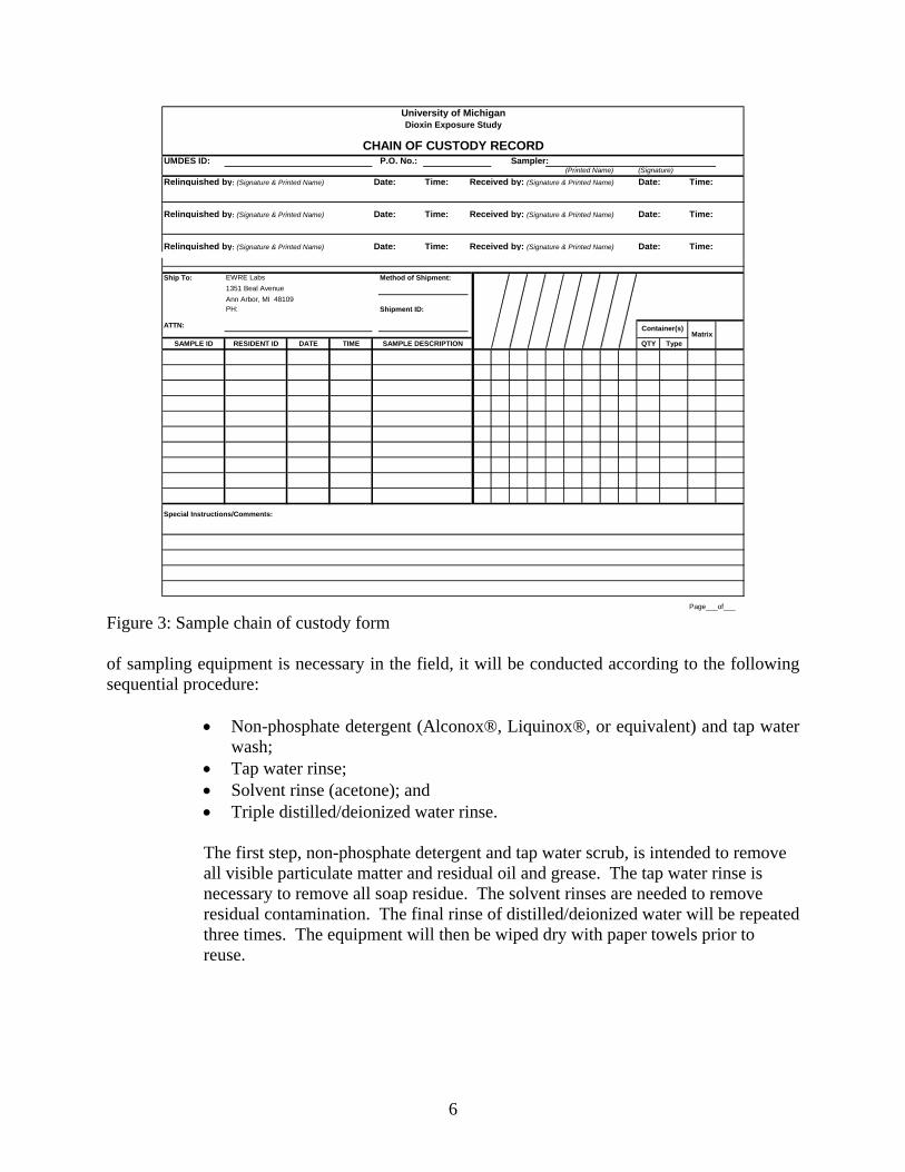
Figure 3: Sample chain of custody form of sampling equipment is necessary in the field, it will be conducted according to the following sequential procedure:
• Non-phosphate detergent (Alconox®, Liquinox®, or equivalent) and tap water wash;
• Tap water rinse; • Solvent rinse (acetone); and • Triple distilled/deionized water rinse. The first step, non-phosphate detergent and tap water scrub, is intended to remove all visible particulate matter and residual oil and grease. The tap water rinse is necessary to remove all soap residue. The solvent rinses are needed to remove residual contamination. The final rinse of distilled/deionized water will be repeated three times. The equipment will then be wiped dry with paper towels prior to reuse.

7
4.2 Storage of Equipment All cleaned sampling equipment will be stored in a clean environment, and covered with aluminum foil.
4.3 Collection and Disposal Procedures
All solvents, residuals, and rinse waters generated during the cleaning of equipment on-site will be collected and transported to UM for proper disposal.
5.0 Sample Compositing
5.1 Introduction
The sealed sample cores will be brought to a staging area in the University of Michigan Environmental and Water Resource Engineering (EWRE) laboratories. Each core will be extruded from the sample holder. Each core from the house perimeter and floodplain stations will be separated into two strata: 0-1 inch, 1-6 inch (Figure 4). The cores from the soil contact stations will be not separated into strata. First a composite will be created for each stratum for each station. An aliquot from each of these composites will be placed in an amber jar and archived. Then the stratum composites from each station will be mixed to create a set composite. Three duplicate samples from each stratum from each soil set will be produced. The collected vegetation for each set will be composited separately from the soil. Ultimately, each residence will yield the following composite samples for analysis:
• House perimeter set 0-1 inch composite; • House perimeter set 1-6 inch composite; and • House perimeter set surface vegetation composite. • If there is a soil contact station or stations, the residence will yield the following
additional samples: • Soil contact set 0-6 inch composite; and • Soil contact set surface vegetation composite (if available). In addition, residences in the Tittabawassee River flood plain will yield the following samples:
• Flood plain set 0-1 inch composite; • Flood plain set 1-6 inch composite; and • Flood plain set surface vegetation composite.

8
Figure 4: Diagram of soil sample core indicating compositing strata
5.2 Procedures The following procedures will be employed to composite soil samples at the EWRE laboratory:
1. Put on booties at door. 2. Put on labcoat and safety glasses. 3. Prior to use, all reused utensils must be scrubbed in water containing 2% Liquinox
solution, followed by rinsing with DI water, methanol, DI water, acetone, and then a third DI rinse.
4. Always wear disposable latex gloves while handling samples. Change to a new set of gloves before handling samples from another station.
5. Put clean paper down on lab counter and tape ends. 6. Retrieve documents from file cabinet for residence to be composited. Sample data
sheet for compositing of soil is shown in Figure 5. 7. Assemble and label bowls or pans. 8. Remove the cores for the particular residence from the cooler room, separating the
cores into the appropriate stations and sets based on documentation records. 9. Remove from plastic bags. Photograph (with the sample label facing the camera) each
set (house perimeter, soil contact zone, floodplain) upright prior to opening any of the samples to document the integrity of the cores. Write sample ID on dryerase board and photograph it with the samples.
10. Examine the cores visually. For any core that seems to be composed of different layers or any core that seems to have a composition different from the others, report the color variation using the Munsell color chart and any other details that distinguishes that core or layer.
0-1 inch stratum
1-6 inch stratum

9
Site
No of No. ofJars Cores
Composite ID Core Names
Additional Notes
Page ____ of _____Compositor
Date of Sample
Signature
Date of Composite
Strata NotesGeneral Core Description
Figure 5: Soil compositing data sheet
11. For each core, remove the tape and caps; be sure to keep the sample horizontal (end
caps may need to be cut with exacto knife). 12. Extrude the sample using the following steps: a) Secure core in the extruder sleeve by tightening bolt. b) Turn on hydraulic pump. c) Activate core movement by turning handle down. d) Hold Teflon sheet in front of piston until pressed against exposed end of core. 13. Place pan under soil core. 14. Extrude only 1” of the soil core. 15. Cut from rest of sample and remove vegetation and place the vegetation into waste
bucket for later disposal. 16. Place soil from 0”-1” stratum in a bowl or pan. Mix. 17. Extrude rest of sample and place 1”-6” stratum into another bowl or pan. Mix. 18. Repeat beginning at Step #11, placing each stratum from the same station into the
appropriate bowl or pan. 19. After placing all soil in the bowl, thoroughly mix the sample until completely
homogeneous as shown by the physical appearance of the soil. 20. Divide the soil in the bowl into two halves. 21. Fill the 4 oz amber sample jar by alternating the soil from each half. 22. Complete the jar’s label with the property ID, date sampled, date composited and the
appropriate code indicating the sample stratum, location and type of composite.

10
23. Use cap and label to seal the jar. 24. If sample is from the house perimeter set, or a soil contact set with two stations,
combine the soil from the same stratum from all stations in equal proportions by volume into one bowl and repeat Steps 19-22. Fill 3 jars with the composited soil.
25. For floodplain cores, Steps 16-23 should be performed in vented hood. 26. Place excess soil in waste bucket for later disposal. Soil contact set and house
perimeter sets soils may be combined. Floodplain soil should be disposed of separately.
27. Complete the chain of custody document and compositing data sheet associated with the batch of samples.
28. Decontaminate all the utensils that will be reused. See Step #3. 29. Place each amber jar in a freezer bag and return to cooler room. 30. Place completed documentation into file drawer for completed residences.
To composite the vegetation samples, the same laboratory procedures will be followed as for soil compositing, Steps 1-7. Then:
8. Remove the vegetation for the particular residence from the cooler room, separating the vegetation into appropriate stations. 9. Photograph with sample ID, sampling date and compositing date written on white board. 10. Examine vegetation. If not grass, note on log sheet. 11. Tare out weight of Ziploc® bag. 12. Weigh the bag with the least amount of vegetation. 13. Record weight and which sample it is on data sheet (Figure 6). 14. Put entire contents of bag in clean stainless steel bowl. 15. Cover scale with foil and tare out weight. 16. Weigh out same amount from each additional bag in turn. 17. Add to bowl. If not grass, then go to 17a below. 18. Toss with stainless steel spoons until mixed. 19. Divide into halves and fill 3 16-oz amber jars by alternating spoonfuls from each side of bowl. 20. If any of the samples is less than 50 g, divide the vegetation into two jars. Minimum sample size is 25 g. 21. Complete the jars’ labels with the property ID, date sampled, date composited and the appropriate code indicating type of sample. Follow Steps 26-30 from soil compositing regarding disposal of excess, completion of documentation and returning samples to cooler room. If the vegetation is not grass: 17a) Deposit contents of bowl on Teflon cutting board and cut into pieces approximately 2 cm by 2 cm using a stainless steel cleaver. Return pieces to bowl. Continue with 18 above.

11
Site
No of wt (g)Jars
Additional Notes
Page ____ of _____Compositor
Date of Sample
Signature
Date of Composite
Strata DescriptionComposite ID Core Names
Figure 6: Vegetation compositing data sheet 6.0 Sample Analysis
6.1 Procedures
All samples that are subjected to analysis will be analyzed for the WHO 29 PCDD, PCDF and PCB congeners by Alta Analytical Laboratory using internal modifications of USEPA methods 8290 (US EPA, 1994) and 1668 (US EPA, 1999). The decision sequence of which samples will be analyzed is shown in Figure 7. The 0-1 inch house perimeter composite sample will be analyzed for all eligible and consented properties. If any part of the property is in the floodplain, then all remaining composites (1-6 inch and vegetation house perimeter; 0-1, 1-6 inch and vegetation floodplain; and 0-6 inch and vegetation soil contact) will also be submitted for analysis. If the respondent does not live in the flood plain, but has a vegetable garden, or works in a flower garden, the 0-6 inch and vegetation soil contact composites will be analyzed. If the TEQ of the 0-1 inch house perimeter composite for any property outside the floodplain is > 8 ppt, then the 1-6 inch and vegetation house perimeter composites will be analyzed. The trigger value of 8 ppt TEQ represent the 75th percentile of the background distribution for the lower peninsula of Michigan (i.e., 25% of soil samples are expected to be above 8 ppt).

12
Figure 7: Soil and vegetation analytic sequence
Stop
no no no Does respondent work in a flower garden or have a vegetable garden?
Start
Measure PCDD, PCDF, and PCB concentrations in 0-1 inch house perimeter composite.
Measure PCDD, PCDF, and PCB concentrations in 0-6 inch and vegetation soil contact composites.
Is residence in the floodplain?
yes
Did pilot study show 0-1 inch house perimeter composite TEQ ≤ 8 ppt but 1-6 inch house perimeter composite TEQ > 8 ppt in 3 out of 24 samples?
yes
Stop
Is TEQ of 0-1 inch house perimeter composite >8 ppt?
no
yes yes
Measure PCDD, PCDF, and PCB concentrations in 1-6 inch house perimeter composite.
Measure PCDD, PCDF, and PCB concentrations in all other composites: 1-6 inch and vegetation house perimeter; 0-1 inch, 1-6 inch and vegetation flood plain; and 0-6 inch and vegetation soil contact composites.
Measure PCDD, PCDF, and PCB concentrations in 1-6 inch and vegetation house perimeter composites.
Stop

13
6.2 Pilot Study
It is assumed that the majority of the presence of dioxin-like compounds in the soil outside of the flood plain is due to atmospheric deposition. Therefore, it is assumed that on any property outside the flood plain where the 1-6 inch stratum contains an elevated level of dioxin-like compounds, the 0-1 inch stratum will be at least above the 8 ppt TEQ trigger value. To verify the assumption that if the 1-6 inch stratum contains elevated levels of dioxin-like compounds, the 0-1 inch stratum does also, a pilot study will be conducted on 24 residences in the Midland/Saginaw area outside of the flood plain. The following procedures will be employed in conducting the pilot study: 1. From the residences in the Midland/Saginaw area in which the 0-1 inch house
perimeter composite yields a TEQ below the 8 ppt trigger: a) Twelve residences will be randomly selected where obvious fill activity
has taken place. b) Twelve residences will be randomly selected where no obvious fill activity
has taken place. 2. The 1-6 inch house perimeter composite will be submitted for congener
specific chemical analysis from these 24 selected residences. The residences in the Midland/Saginaw area will be targeted as there may be a greater likelihood of elevated subsurface concentrations of dioxin-like compounds in those areas because of the reputed use of Tittabawassee and Saginaw River flood plain sediment as fill material. If more than 3 of the 24 1-6 inch composite samples yield a TEQ above the 8 ppt trigger, the 1-6 inch house perimeter composite from all the properties in the Midland/Saginaw area will be analyzed.
6.3 Shipping Procedures
1. Samples for chemical analysis will be shipped according to 40 CFR 761.65
(i)(3) and in accordance with current and applicable D.O.T. standards. 2. The following chain-of-custody procedures will apply to sample shipping:
a) Relinquish the sample containers to the laboratory via express carrier. The signed and dated forms should be taped inside the top of the cooler. The express carrier will not be required to sign the chain-of-custody forms.
b) When the samples are received by the laboratory, the laboratory personnel shall complete the chain-of-custody forms by signing and dating to acknowledge receipt of samples. The internal temperature of the shipping container is measured and recorded. The sample identification numbers on the containers are then checked to insure that they are consistent with the chain of custody forms.

14
7.0 References United States Environmental Protection Agency (US EPA). Method 1668, Revision A: Chlorinated biphenyl congeners in water, soil, sediment, and tissue by HRGC/HRMS. Washington, DC: Office of Water, 1999. United States Environmental Protection Agency (US EPA). Method 8290: Polychlorinated dibenzodioxins (PCDDs) and polychlorinated dibenzofurans (PCDFs) by high-resolution gas chromatography/high-resolution mass spectrometry (HRGC/HRMS). Washington, DC: Office of Solid Waste and Emergency Response, 1994.