appendix 5 materials related to “chapter 3 railway
TRANSCRIPT

Ap.5-1
APPENDIX 5
MATERIALS RELATED TO “CHAPTER 3 RAILWAYTECHNICAL STANDARDS”
5.1 Interpretation Guidelines
These interpretation guidelines are intended to supplement implementation of railway
technical standards by clearly demonstrating the thinking, interpretation and specific figures
for the said standards.
For this reason, stipulations of the interpretation guidelines are only stated for those parts of
the railway technical standards where interpretation is required.
Chapter 1 General
1.1 Definition of Terminology
1.2 Preparation of Implementation Standards
Chapter 2 Qualification, Education and Training of Railway Employees
2.1 Education and Training of Railway Employees
A railway operator shall provide the necessary education and training for those railway
employees directly related to train operation.
2.2 Qualification of Railway Employees (Obtaining of Certificate)
Motive power units (electric rolling stock; internal combustion rolling stock) shall only
be operated by those who have obtained the certificate for train drivers published by
DOTC or official agencies.
The "employees directly related to train operation" are as follows.
(1) Employees who operate a train or rolling stock
(2) Employees who execute train operation control, such as alteration of the sequence of
train operation; alteration of train exchange conditions; and cancellation of train
operation

Ap.5-2
(3) Employees who ride on a train in order to give signs on train protection, brake handling,
push operation, and so forth
(4) Employees who execute route control for trains or rolling stock; blocking; railway signal
handling; or point handling
(5) • Employees who lead and supervise activities directly related to train operation, in
maintenance works and so forth of tracks, electric wires, or operational safety devices
• Employees who perform the above activities directly related to train operation, in the
case where there are no employees who lead and supervise such activities
(6) Employees who handle safety devices for level crossings
Chapter 3 Tracks
3.1 Gauge and Slack
The gauge shall be decided to ensure the smooth running of rolling stock, taking the
structure of vehicles and others into consideration. At curves, appropriate slack shall be
provided in accordance with the curve passing performance of rolling stock.
When rolling stock passes through curves, it is ideal from the viewpoint of smooth
rolling stock running for wheel faces to be parallel with rails (for wheel axles to be at
right angles with rails). However, because at least two wheel axles are fixed to bogies,
etc., at least one of the wheel axles cannot be at right angles to the rail. Accordingly,
wheels passing through curves advance at a certain angle to the rails. In actual rolling
stock, because there is movable allowance in the right angle direction from rails between
the wheel flanges and rails, the rolling stock can pass quite safely up to a certain curve
radius, however, when the curve radius becomes smaller, the wheels and rails grate
against each other and smooth running is no longer possible. For this reason, track gauge
on curves is made wider than on straight sections depending on the curve radius, the
number of axles fixed to bogies, and the shape of wheels, etc. This expansion of gauge
on curve sections is known as slack. Moreover, since over-expansion of gauge can affect
the running safety of rolling stock, it is necessary to keep slack to a minimum.
Slack criteria are as indicated below.
(1) Maximum value of slack
1) On sections with a gauge size of 1.067 m and 1.435 m, slack must not exceed 25
mm.
2) 1) Sections where cars with two axles are the only rolling stock to run.( ) η−×= RS 2/11000max 2

Ap.5-3
3) 1) Sections other than 1)
( ) η−×= RS 32/911000max 2
Note:
Smax: maximum slack (mm)
l: Maximum rigid wheel base (m) of passing rolling stock
R: curve radius (m)
η: moving allowance (mm)
(2) Minimum value of slack
1) Sections where cars with two axles are the only rolling stock to run.
( ) η−××= RrhS /211000min
2) Sections other than 1)
( ) η−×= RS 8/11000min 2
Note:
Smin: minimum slack (mm)
l, R and η: same as in 1)
r: wheel radius (m)
h: wheel flange height (m)
3.2 Curve Radius
An appropriate curve radius shall be adopted based on the standard minimum curve
radius to ensure the smooth running of rolling stock, taking the curve passing
performance and running speed of vehicles and the cant, etc. into consideration. In the
case of a curve along a platform, its radius shall be as large as possible to ensure the
smooth boarding/alighting and safety of passengers.
3.3 Cant
A circular curve shall be provided with cant in accordance with the gauge, radius of
curve and speed of rolling stock, etc. It must be ensured that the largest value of the cant
will not adversely affect the stability, etc. of rolling stock which is either traveling at a
low speed or which is stationary.
Common items to 3.2 and 3.3

Ap.5-4
The load conditions of rolling stock passing through curves are as indicated in Fig. 5.1.1
and Fig. 5.1.2. The occurrence of centrifugal force in rolling stock as it passes through
curves causes the following problems:
① Passengers experience discomfort (riding comfort is poor).
② Large stress is placed on outside rails (outside rails on curves), making it necessary
to carry out more track maintenance.
③ Rolling stock will overturn if the centrifugal force becomes too big.
For this reason, outside rails are generally made higher than inside rails on curve sections
in order to reduce the effect of centrifugal force.
Cant refers to the difference in the height of the outside rail.
(1) Balancing cant
The type of cant where the sum total ® of force pushing rolling stock to the outside of
the curve (centrifugal force: F) plus the dead load (W), works towards the center of the
inside and outside rails (R is perpendicular to the rail level) is known as a balancing cant
(Cb). In this state, riding comfort for passengers is good too.
Cb = 8.4 ×(V2/R) … In case of 1,067 mm gauge
Cb = 11.8 ×(V2/R) … In case of 1,500 mm gauge
V: rolling stock passing speed (km/h)
R: curve radius (m)
Moreover, in cases of 1,435 mm gauge in Japan, the height difference (level, cant)
between left and right rails is controlled assuming gauge of 1,500 mm.
(2) Maximum allowable cant (Cmmax)
A large cant is desirable in order to achieve fast running speeds of rolling stock,
however, because overly large cant causes the following problems on curves, railway
operators prescribe maximum allowable cant.
1) Cross winds coming from the outer sides of curves may cause stationary or slow
moving rolling stock to overturn (generally speaking, rolling stock which is running
at very slow speed is at most risk).

Ap.5-5
2) Passengers experience discomfort caused by tilting of rolling stock when the rolling
stock is stationary or moving at slow speed.
Moreover, on narrow gauge railways in Japan (1,067 mm gauge), the allowable value of
cant is where the sum total of force (dead load) working on stationary rolling stock on a
curve with cant does not work towards the outside because of the central triple point of
the gauge. The relationship at this time is shown by the following expression (see Fig.
5.1.1):
Cmmax = B2/0.006H
Cmmax: maximum allowable cant (mm)
B: gauge (m)
H: height from rail surface to rolling stock center of gravity (rolling stock
center of gravity height) (m)
Moreover, on Shinkansen the maximum cant is set at 200 mm due to the limit on riding
comfort as dictated by the tilt of rolling stock.
Example of JR East Japan concerning Cmmax on ordinary railways:
① Gauge: 1,435 mm … Cmmax = 200 mm
② Gauge: 1,067 mm … Cmmax = 140 mm (dual gauge sections)
③ Gauge: 1,067 mm … Cmmax = 110 mm (sections where locomotive trains do not run)
④ Gauge: 1,067 mm … Cmmax = 105 mm (other sections)
(3) Allowable cant deficiency (Cdmax)
In cases where cant is small with respect to the passing speed of rolling stock on curves,
problems that can be considered are deterioration of passenger riding comfort, vibration
of rolling stock, and overturning of rolling stock caused by cross winds from the inside of
the curve. Therefore, when conditions such as track structure and rolling stock
performance, etc. are in place, the passing speed of rolling stock on curves is determined
by the difference between centrifugal force when rolling stock passes through the curve
and centrifugal force which is canceled by the set cant, and the amount of cant which is
equivalent to this difference in centrifugal force is known as the cant deficiency (Cd).
This relationship is shown in the expression Cb = Cm + Cd (where Cb is the balancing
cant, Cm is the set cant, and Cd is the cant deficiency).

Ap.5-6
Concerning the allowable cant deficiency, there is no problem in terms of rolling stock
overturning if the sum total of the aforementioned difference in centrifugal force, wind
force from the inside of the curve, and rolling stock dead load does not work towards the
outer side of the gauge, however, currently in Japan, deterioration in riding comfort
caused by excess centrifugal acceleration (limit is 0.08 g) is adopted as a guide for
determining the allowable cant deficiency, and this is then set for each type of rolling
stock.
Example of JR East Japan concerning Cdmax:
① 381 Series and 383 Series trains, etc. (tilt trains) … Cdmax = 110 mm
② 400 Series and E3 Series trains (mixed operation of small Shinkansen cars and
conventional – line cars) … Cdmax = 90 mm
③ 183 Series, 485 Series, 651 Series trains, etc. (limited express trains) … Cdmax =
70 mm
④ Electric railcars, diesel railcars … Cdmax = 60 mm
⑤ General trains … Cdmax = 50 mm
(4) Minimum curve radius (maximum speed on curves)
1) Thinking 1
The relationship between cant and the velocity of rolling stock passing through a
curve is demonstrated by the following expression.
Cbmax = Cmmax + Cdmax = αV2/R
(α is 8.7 when gauge is 1,067 mm, and 11.8 when gauge is 1,500 mm)
(Cbmax, Cmmax, Cdmax, V and R are the same as shown above).
Therefore, by substituting the maximum speed of rolling stock which passes through
a section, the maximum allowable cant and the allowable cant deficiency of rolling
stock with the worst conditions into the above expression, it is possible to obtain a
rough guide to the minimum curve radius for that section.

Ap.5-7
Calculation example
R = αV2/Cmmax + Cdmax
= 8.7×1102÷(105+50) = 638÷600m
Example of minimum curve radius (Rmin) established in Japan:
Rmin = 600m…110km/h<Vmax
Rmin = 400m…90km/h<Vmax≦110km
Rmin = 250m…70km/h<Vmax≦90km
Rmin = 160m… Vmax≦70km
Rmin = 160m…cases which are unavoidable due to topographical conditions,
etc.
2) Thinking 2
Curve passing performance differs according to each rolling stock. Basically
speaking, if the center of gravity of rolling stock is low, the rolling stock can pass
through a curve without the sum total of centrifugal force and dead weight acting
towards the outside of the gauge.
When cant is set at zero, the following expression can be used to show the
relationship between centrifugal force (F), dead weight (W), gauge (B), height of
rolling stock center of gravity (H), and separation (D) from the center line of track at
the point where the sum force and rail surface intersect.
F(=mV2/R)/W(=mg) = D/H (m is mass, and g is gravitational acceleration)
When converted, this expression becomes V2 = 127 BR/(2aH) (a = B/2D: safety
factor), and the minimum curve radius can be established according to the
performance (height of center of gravity) gauge rolling stock and design maximum
velocity.
On JR East Japan, concerning ordinary railways used by various types of rolling
stock, curve passing speed is prescribed in the Train Operation Regulations for each
type of rolling stock.
Example of curve-separate speed restrictions in JR East Japan

Ap.5-8
① High performance trains … V≦3.7 R
② General trains … V≦3.5 R
③ Turnout curves … V≦3.5 R
Note: Values obtained in the above expression are rounded off as basic speed to units of 5 km/h for
each curve. Figures are also prescribed according to each type of rolling stock.
(5) Curve radius of lines along platforms
On platforms, because there are numerous obstacles to visibility such as the pillars which
support platform roofs, etc., if the curve radius of lines along platforms is small, it is
difficult for train and station personnel to detect danger when trains are passing, etc.
Moreover, to ensure the safe passage of trains through curves, it is necessary to widen the
distance between structures and track center lines. Moreover, if the gap between platform
edge and rolling stock becomes too large, smooth boarding and alighting by passengers is
hindered. Therefore, it is necessary to make the curve radius of lines along platforms as
large as possible.
Moreover, in Japan, the minimum curve radius of lines along platforms is set at 400 m
(minimum curve radius is 300 m on sections where only rolling stock measuring less
than 18 m passes).
3.4 Transition Curve
A transition curve shall be provided between a straight line and a circular curve or
between two circular curves depending on the structure, degree of cant and traveling
speed of rolling stock, etc.
On transition sections between straight lines and circular curve, and on curve sections of
differing curve radius, the cant and curve radius will differ. If cant and curve radius
suddenly change on such sections of differing cant and curve radius, since the running
safety of rolling stock and riding comfort of passengers will deteriorate, transition curves
are adopted to ensure smooth alteration of cant and curve radius and smooth running of
rolling stock.
Concerning the required length of transition curves, the longest value obtained from the
following three expressions is used for each curve:

Ap.5-9
L1 = K1Cm
L2 = K2CmV
L3 = K3CdV
(1) Value based on safety with respect to three-point support (L1)
On sections where the cant changes, the cant differs between axles fixed onto car
bogies, etc. and a condition of three-point support exists. Accordingly, since there is
a risk of at least one axle rising up and derailment taking place, this danger is
averted by restricting the amount of change in cant.
(2) Value based on the limit in riding comfort with respect to the ratio of cant change
over time (L2)
On sections where the cant changes, the car body rotates as an axle in the
longitudinal direction of the track, however, since riding comfort deteriorates when
the rotating speed is too large, a limit is placed on this rotating speed.
(3) Value based on the limit in riding comfort with respect to the ratio of change in
excess centrifugal force over time (L3)
Length is obtained from the amount of change in excess centrifugal force on a
transition curve which can be allowed up to a level equivalent with the centrifugal
force experienced by passengers passing through a circular curve.
Moreover, on transition curves in Japan, tertiary parabolas, sine curves and clothoid
curves, etc. are frequently used.
Example of transition curve lengths in Japan:
1) In case of gauge: 1,067 mm, velocity: more than 75 km/h
L1 = 600Cm
L2 = 8CmV
L3 = 9CdV
2) In case of gauge: 1,067 mm, velocity: 75 km/h or less
L1 = 400Cm
L2 = 7CmV
L3 = 9CdV

Ap.5-10
Maximum value or more out of (1) and (2) above
In both (1) and (2), meters (m) are adopted as the unit for L1, L2, L3, Cm and Cd,
while km/h is adopted for V.
3.5 Grade
The grade of the track shall be determined in consideration of the power performance,
braking performance and speed of operation, etc. of rolling stock and the standard
steepest grade for main lines is given below. A grade as gentle as possible shall be
introduced on a main line along a platform and storage siding, etc., taking the rolling
motion, etc. of rolling stock into consideration.
Track grade is determined with consideration given to the power performance, braking
performance and operating speed, etc. of rolling stock appropriate for the transportation
plan on the section in question. In Japan, concerning sections where locomotive-hauled
trains are operated, the maximum grade is established according to the design haulage
load on the section in question, while on other sections a figure of 3.5% is adopted as the
maximum grade. Also, maximum grade on train stop sections of main lines is set at
0.5%, but 1.0% can be adopted on train stop sections where storage and decoupling are
not carried out. Moreover, maximum gradient on sidings in districts where storage and
decoupling of rolling stock takes place is 0.5%.
3.6 Vertical Curve
In places where the grade changes, a vertical curve shall be introduced to prevent the
derailing of rolling stock and to prevent any unpleasant feeling on the part of passengers,
taking the speed of train operation and rolling stock performance, etc. into consideration.
Items which are a problem when determining the vertical curve radius are as follows.
(1) Safety with respect to lifting of rolling stock
There are two major problems, and one of these mainly occurs in locomotive-hauled
trains. When shifting from a flat section to a downhill grade, upward force is
generated when the train applied the brakes and is pushed by rolling stock to the
rear, so it is possible that the safety of rolling stock in which brakes were applied
may be affected. Generally speaking, this is not a problem on trains other than very
long freight trains.

Ap.5-11
As for the second problem, when a running train transfers from an uphill grade to a
downhill grade, the centrifugal force which accompanies the train running causes the
rolling stock to rise. The vertical acceleration which is placed on rolling stock as it
passes through a vertical curve with a general radius is demonstrated by the
following expression.
α = 1/Rg×(V/3.6)2
α: vertical acceleration (gravitational unit)
R: vertical curve radius (m)
g: gravitational acceleration (9.8 m/sec2)
V: velocity (km/h)
The allowable value for α is said to be around 0.1, so if α = 0.1 and V = 100 km/h
are assumed in the above expression, R = 787 m is obtained.
(2) Construction gauge and rolling stock gauge
On vertical curves, rails in the center of curves are closer to the rolling stock side
than rails at the start and finish points of curves. These values are demonstrated by
the following expression:
D = L2/8R
D: value where rails are close to rolling stock (m)
R: vertical curve radius (m)
L: bogie center-to-center distance (m)
When L = 13.4 m and R = 3,000 m are put into the above expression, D = 7.5 mm is
obtained, and this is considered to offer ample safety with respect to the rail level
vertical limit of 50 mm in Japan.
(3) Examination concerning riding comfort
The allowable value for vertical centrifugal force with respect to riding comfort is
said to be 0.02-0.04 g. If α = 0.04 and V = 100 km/h are inserted into the expression
shown in (1), r = 1,968 m will be obtained.
Example: vertical curve radius set in Japan

Ap.5-12
① Grade change on main line: 1% or more … R≧3,000 m
Grade change on main line: 1% or more … R≧4,000 m (level curve radius:
800 m or less)
② Unavoidable cases due to topographical conditions, etc. … R≧2,000 m
Unavoidable cases due to topographical conditions, etc. … R≧3,000 m (level
curve radius: 800 m or less)
3.7 Construction Gauge
The construction gauge shall be determined to ensure the safety of rolling stock and
passengers, etc. vis-à-vis the pitching or rolling, etc. of traveling rolling stock and no
structure shall be introduced within the construction gauge.
In Japan, construction gauge and rolling stock gauge are both designated: in
consideration of pitching and rolling of traveling rolling stock, clearance of 400 mm is
provided on both sides of the rolling stock gauge. Moreover, as for the construction
gauge on sections which run along platforms, 50 mm is added to the rolling stock gauge.
Moreover, on curves, the construction gauge is expanded in accordance with rolling
stock eccentricity.
3.8 Width of Formation Level
The width of the formation level shall be determined to ensure the safety of passengers
and workers, etc. in consideration of the pitching motion of traveling rolling stock and
the track structure, etc.
3.9 Center-to-Center Distance of Adjacent Tracks
The center-to-center distance of adjacent tracks shall be determined by adding a margin
to the width of rolling stock in consideration of pitching motion to ensure its safety and
of the passengers. This distance shall be widened at curves, etc. in response to the
expected swaying, etc. of rolling stock.
In Japan, in consideration of pitching and rolling of traveling rolling stock, a margin of
600 mm is added to the rolling stock gauge in order to obtain the center-to-center
distance of adjacent tracks on straight sections. Moreover, on curves, the center-to-center
distance of adjacent tracks is expanded in accordance with rolling stock eccentricity.

Ap.5-13
3.10 Track and Civil Engineering Structures
Track and civil engineering structure shall be determined to ensure the safety and
security of the rolling stock and railway facilities in consideration of the structure of
rolling stock, train weight and subgrade conditions, etc.
3.11 Building Construction
Buildings shall be constructed so as not to compromise the safety of the rolling stock and
passengers.
3.12 Disaster Prevention Devices, Safety Devices and Evacuation Devices
Disaster prevention and safety devices shall be installed to avoid entry of unwanted
persons and of falling objects onto the tracks. Similarly, measures shall be applied to
prevent damage to the facilities which may be brought about by accidents or any
untoward incidents happening in the perimeter area. In addition, evacuation devices
designed to safely guide passengers at the time of an accident or an emergency will be
set up.

Ap.5-14
Fig. 5.1.1 Force at Work on Rolling Stock as it Passes Through a Curve

Ap.5-15
Fig. 5.1.2 Force at Work on Rolling Stock as it Passes Through a Curve at Low Speed

Ap.5-16
Chapter 4 Station Facilities
4.1 Specifications for station facilities such as effective track length, platform length/width,
etc. shall be determined so as to ensure smooth train operation with consideration for
passenger safety.
(1) The effective length of line in stations shall be enough to accommodate the longest train
at a stop in the station (see Fig. 5.1.3).
D1: Center-to-center distance of adjacent tracks at points where clearance posts
are erected.
Fig. 5.1.3 Effective Length of Line in Stations
• To allow trains to pass the adjacent track without any problem, the effective length
of line shall be sufficient enough to accommodate the longest train operating on the
line concerned.
effective length of line = longest train length + allowance(generally 35m)
• Train Limit markers shall be positioned where the line spaceing is equivalent to the
total of the specified construction gauge and the displacement (α) caused by curves
and cant.
The line spaceing D1 = construction gauge + α
longest train length
effective length of line
Line spaceing :D1
Cle
aran
ce P
oint
effective length of platform
××
Cle
aran
ce P
oint

Ap.5-17
(2) Station facilities
1) General
① In stations, efforts shall be made to install escalators, elevators and slopes at
graded points, in order to secure the passage of users with impaired mobility, etc.
a) Stations where escalators should be installed and number of escalators to be
installed
ⅰ) New stations or stations undergoing major renovation
• In new stations or stations undergoing major renovation, escalators are
installed as basic station facilities on graded passages between walkways
and free corridors, between free corridors and platforms, and between
platforms, etc., in order to assist users with impaired mobility and to
promote use of railways.
• As a rule, concerning separate graded corridors, upward and downward
escalators shall be installed on at least one corridor.
Note: Major renovation refers to station-wide works in cases of the transfer of stations,
elevation of stations or underground expansion of stations, etc. This refers to
rebuilding of station buildings and comprehensive renovation which includes
corridors and stairways.
ⅱ) Existing stations
• In existing stations which fulfill the following conditions, escalators shall
be installed as soon as possible. Generally speaking, effort shall be made
to carry out planned installation within around 10 years with
consideration given to number of users, level of cooperation from the
local community, topography, station structure, and so on.
• In stations where the daily number of boarding and alighting passengers
is 5,000 or more, upward and downward escalators shall be installed on
at least one passageway in the following cases:
- Where the aggregate height in the upward direction between the
platform and public corridor is 5 m or more
- Where the aggregate height in the upward direction between platforms
is 5 m or more

Ap.5-18
• In cases where escalators cannot be installed in both directions,
escalators shall be installed in at least one direction.
• It is desirable to install escalators on corridors which have particularly
large numbers of users.
ⅲ) Structure of escalators
In stations which do not have elevators or slopes, the structure of escalators
shall as a rule be designed so that wheelchair users can board them.
b) Stations where elevators, etc. should be installed and installation sites
ⅰ) In new stations or stations undergoing major renovation, where height
differences cannot be overcome by means of slopes, at least one elevator
each shall be installed between walkways and free corridors, between free
corridors and platforms, and between platforms.
ⅱ) Concerning existing stations where there is a height difference of at least 5
m and the daily number of users is 5,000 or more, effort shall be made to
successively carry out planned installation with consideration given to
number of users, level of cooperation from the local community,
topography, station structure, and so on.
ⅲ) Structure and installation position of elevators
• The structure of elevators shall be such that wheelchair users can utilize
them.
• Providing there are no problems in terms of structure, elevators shall be
installed in easy to use positions so that other persons apart from
wheelchair users can utilize them.
② Free corridor
• Free corridors shall be provided not to cause division of the area along the line.
2) Platforms
① The effective length of platforms shall comfortably accommodate the longest
trains that arrive at and depart from each platform in question.

Ap.5-19
effective platforms length of=longest train length + allowance(generally 10m)
② The width of platforms shall be sufficient not to hinder the flow of passengers.
On platforms where both sides are used, standard width shall be 3 m in the
center and 2 m at ends; while on platforms where only a single side is used,
standard width shall be 2 m in the center and 1.5 m at ends.
③ The standard distance between pillars on platforms and the edges of platforms
shall be at least 1 m.
④ The standard distance between overpasses and entrances to underground
passages on platforms and the edges of platforms shall be at least 1.5 m.
According to 2) through 4) above, minimum dimensions for islands platforms
shall be as shown below (see drawing).
Platform width = 1.5×2 + maximum width of structures on platform
However, from the viewpoint of wheelchair users and risk prevention on
platforms, width of at last 2.0 m is desirable. In this case, the above expression
will be converted as follows.
Fig. 5.1.4 Required Platform Width, etc.
⑤ The gap between the platform edge and the floor level or footstep of trains shall
be made as small as possible, providing that there is no adverse impact on the
running of trains.
Necessary platform width
1,500 mm ormore
Calculated valueor more
300
Stairway ESC Pillar
1,650 mmif for useby two
++++++++
300 200
1,000 mm ormore

Ap.5-20
⑥ The height difference between the platform and the floor level or footstep of
trains shall be made as small as possible, providing that there is no adverse
impact on the safe and smooth boarding and alighting of trains by passengers.
4.2 Smooth Transfers between Railway Line
Railway proponents shall plan through train services by constructing or improving
railway facilities in cooperation with other railway proponent, or, shall plan the stations
in the same location with or adjacent to the stations of other railway lines to facilitate
transfers between railway lines by proponents.
When planning the layout of stations, consideration must first be given to the mutual transfer
plan to ensure smooth transfer between different railway lines. Moreover, at intersecting or
connecting stations, layout must be designed so that stations are located adjacent to each other
or in the same place.
4.3 Smooth Transfers between Railway and Road-based and Other Modes of Transport
Railway proponents shall plan appropriate type of station plazas in cooperation with
relevant road management agencies/operators prior to the construction or improvement
of railway facilities to allow smooth transfers from road-based and other modes of
transport.
When planning the layout of stations, efforts shall be made to build close to bus and jeepney
terminals, etc. and areas of concentrated business, commercial and residential functions so
that the railway is easy to use. Moreover, the quality of services shall be improved through
installing station plazas and connecting facilities and providing facilities that are safe and
pleasant to use.

Ap.5-21
Chapter 5 Power Facilities
5.51 Contact Line (Overhead trolley wire and third rail)
5.1.1 The voltage of contact lines shall be maintained at a stable level sufficient to
ensure smooth train operation.
Because traction circuits have electrical resistance and voltage drop occurs when an
electric railcar load current passes by, the voltage is sent out at a higher level from
substations.
However, it is undesirable from a rolling stock maintenance standpoint for traction
voltage to be too high because this induces breakdowns to occur in electric railcars and
sparks to occur in other electrical equipment.
Moreover, when traction voltage drops, the speed characteristics of electric railcars also
decline, auxiliary machine functions are lost, and the control circuitry motors of railcars
suffer voltage deficiency and cease to operate normally below a certain level.
The standard voltage of contact lines shall be DC 1,500 V and DC 750 V for catenary
wires, and DC 750 V for third rail.
Threshold voltage in Japan are shown below:
Table 5.1.1 Standard Voltage in Japan
Standard voltage Maximum voltage Minimum voltage
600V 720V 400V
750V 900V 500VDC
1,500V 1,650V 900V
20kV 22 kV 16 kVAC
25 kV 30 kV 22.5 kV
The IEC (International Electricity Standards Conference) Standards on voltage
fluctuations are as follows:

Ap.5-22
Table 5.1.2 Standard Voltage in IEC
Electricsystem
Standardvoltage
Maximumvoltage
Minimumvoltage
Remarks
600V 720V 400V
750V 900V 500V
1,500V 1,800V 1,000VDC
3,000V 3,600V 2,000V
6,250V 6,900V 4,750V 50Hz or 60Hz
15,000V 16,500V 12,000V 162/3Hz
25,000V 27,500V 19,000V 50Hz or 60HzAC
50,000V 55,000V 38,000V 50Hz or 60Hz
Existing contact line voltage on Metro Manila's LRT are the following:
Table 5.1.3 Contact line Voltage on Metro Manila’s LRT
Standard voltage Maximum voltage Minimum voltage
Line 1 DC 750V 900V 525V
Line 3 DC 750V 900V 500V
5.1.2 Contact lines shall be capable of collecting power evenly and continuously in
accordance with the speed of the train and the power collection method of the
rolling stock.
In general, railways shall adopt single overhead wire lines. In selecting the carrying
cable, the type of system required on each section must be determined after a
comprehensive assessment of voltage drop, construction cost, extent of renovation of
obstructions, performance of electric railcars, structure of current collectors, cross winds
and other related items without prejudice to the following prerequisites:
- Required operating speed must be satisfied; and
- Required power collection capacity must be satisfied.
The main conditions that must be fulfilled by contact lines and power collection devices
are as follows:

Ap.5-23
(1) The height and displacement of contact lines must comply with the operating range
of power collection devices. Moreover, contact line fittings (such as pull-off
devices) should not hinder operation.
(2) To ensure sufficient current flow for electric railcars, consideration must be given to
voltage drop and temperature rise.
(3) Notwithstanding any contact line vibration, disconnection, or arcs that tend to rise
with increases in the contact line grade, grade changes, train speed and quantity of
power collection devices, the deviations must be within tolerable levels that will not
hinder power collection.
(4) Sufficient mechanical strength and structural allowance shall be provided with
respect to expected changes in the external environment, such as wind, snow, ice,
rain, and temperature, etc.
(5) In addition to possessing enough mechanical strength to withstand force exerted
during running through intersections and sections, etc., power collection devices
shall possess air dynamic characteristics that prevent the occurrence of abnormal
uplift.
Options for contact lines
Contact lines shall be installed as overhead single wire lines. However, in cases of
underground railways, overhead railways and railways housed in special compounds
which cannot be easily entered by outsiders, third rail systems may be adopted.
Installation of overhead contact lines
In installing catenary or overhead contact lines, the following conditions shall be
adhered to:
1) The carrying method shall be in accordance with the operating speed of trains;
2) The standard distance between hangers shall be 5 m;
3) Tension adjusters shall be installed at appropriate intervals of contact lines and
messenger wires; and
4) Brace and pull-off devices shall be of the kind that bear no risk of hindering
train operation.

Ap.5-24
Height of catenary
The height of contact wires shall be restricted to pre-set ranges in order to stabilize
power collection, conform to standards, limit the amount of occupied space, prevent
electric shocks, and avoid obstruction of traffic on level crossings.
The standard height of overhead single wire contact lines shall be between 5.0 to 5.4
m.
The overhead contact lines deviate from its alignment in various ways, even when
undisturbed. For example, there is zigzag deviation to accommodate the replacement
interval of pantograph contact strips. Or, deviation resulting from line alignment at
curve sections and intersections and deviation arising from the state of track
maintenance. External forces may also cause other deviations. The most common is
deviation caused by wind and pitching of rolling stock when the train is in motion.
The pantograph is supposed to be perpendicular at all times to the track level at the
track center. However, there are instances when it is out of position or appears
deviated. This deviation shall be no more than 250 mm from the perpendicular to the
rail surface at the track center.
Notwithstanding any of the foregoing deviations, contact between contact line and
pantograph shall be maintained at a steady state. Moreover, the pantograph shall not
detached from the slider portions under ordinary train pitching. The maximum
deviation is constrained by the length of the pantograph slider, which is 1.0 to 1.1 m
in length. Neither shall the effective pantograph width (known as the wedging
threshold, roughly 1.3 m) be exceeded under harsh conditions such as high winds,
typhoons, etc..
Installation of third rail contact line
Third rails shall be installed in accordance with the following conditions.
(1) Protective gear shall be provided around third rails to prevent human contact;
with the gap between the third rail and the protective gear (upper protective
plating only) shall be at least 75 mm.
(2) In stations, third rails shall be installed on the opposite side of platforms
whenever feasible. When the station structure precludes such installation, the
third rail should have upper protective plates and front protective plates.
(3) The end of third rail fulcrum points shall be 5 m or less.

Ap.5-25
(4) Expansion joints and anchor links shall be installed at appropriate intervals of
the third rail.
(5) Interval between third rail shall be such that the sliding of collector rings is not
impeded.
5.1.3 Return rail shall be designed in such a way that the leakage current from rail to
ground is minimized .
Because the rail on which the train runs is used as the "return rail" for DC electrified
sections, inevitable leakage of current from rail to ground sometimes causes electric
erosion to occur in nearby metal conduits, rails, fastening devices (dog spikes, etc.) and
sheds.
Electric erosion refers to the phenomenon whereby electrolysis causes corrosion to occur
in metal bodies when current flows out from metals buried underground.
Because the return rail is not totally insulated from the ground (ground leakage resistance
on track inclusive of ballast is about 10-5,000 Ωkm, on exclusive-use track), part of the
current passing through rails flows into the ground via the sleeper and ballast. This is
known as leakage current from return rails.
The size of leakage current is inversely proportional to ground leakage resistance, but it
is proportional to electric potential (voltage drop of rails) between rail and the ground.
Methods for reducing leakage current can be summarized as follows:
(1) Increasing ground leakage resistance
Use of insulation pads, full installation of line drainage facilities, water leakage
prevention in tunnels, replacement of defective sleepers
(2) Reducing rail-ground electric potential
Adoption of long rails, adoption of large section rails, additional use of cross bonds,
total maintenance of rail bond facilities
Rails are usually connected by fish plates and bolts. Where fish plates only are
involved, electrical contact resistance becomes unstable and the rails are electrically
connected by means of a bond. The electrical resistance at joints (including

Ap.5-26
connected bonds, which is the sum of bond conductor resistance, bond terminal
resistance, contact resistance between terminals and rails, and contact resistance of
rail fish plates) is generally no more than a resistance value equivalent to 1-2 m.
Return rail joints are electrically connected using bond. The joints of return rails on
DC contact lines shall have an electrical resistance of 5 m or less (rail-conversion
resistance).
5.2 Substations
5.2.1 Substations shall be constructed in such a way that their safety and security are
ensured.
Substations refer to facilities installed with rectifiers, transformers and other electrical
equipment for transforming electricity that is transmitted from external sites and sending
it on to other outside destinations.
Because electrical equipment at substations is connected to external power lines (return
power lines, contact lines, transmission and distribution lines), any malfunction inside
substations or secondary accidents with external ripple effects shall be prevented from
spreading outward. Conversely, the substation must be protected from external
disturbances and other accidents on power lines.
Equipment security systems
The following security devices shall be installed in substations.
(1) Automatic breakers for protecting transformers on special high voltage or high
voltage AC lines (receiving side).
(2) Automatic breakers on the return side to counter breakdown currents on return lines
(load side)
(3) Protective devices to counter overload (in main circuitry transformers on the AC
side).
(4) Protective devices to counter power supply anomalies (receiving voltage)
(5) Protective devices for transformer equipment (conductor rectifiers)
• Protective devices to counter temperature increase in equipment
• Protective devices to counter breakdowns in coolers

Ap.5-27
• Protective devices to counter abnormal voltage
An automatic breaker refers to a device that detects occurrence of breakdowns in circuits,
and in response, automatically releases/cuts off the current.
Protective device refers to a device which detects anomalies in equipment and circuits
and issues alarms or breaker commands.
Prevention of trespassing in substations
In order to prevent unauthorized entry of persons into substations, fences and moats shall
be provided, entrances shall be locked, and ‘No entry’ signs shall be posted.
5.2.2 Substation equipment shall have the capacity to meet its specified load as well
as withstand specified overloading conditions.
Calculation of substation capacity
Electric railway load is subject to extreme fluctuations that make it difficult to decide the
capacity of rectifiers. Load capacity on the train side can, to a certain extent, be
accurately calculated by assessing motor characteristics curve and operation curve.
However, due to the complexity of calculating line loss under moving load conditions,
capacity can not be accurately determined without resorting to computer simulation. A
practical approach is to base rectifier capacity to actual performance data of rolling stock
base units, or by referring to monographs such as “Gauging of Electric Railway Load and
Selection of Rectifier Capacity According to Line Section” [Technical Report No. 56 of
the Institute of Electrical Engineers of Japan]. This technical report suggests a number
of simple calculation methods for gauging the electric railway load, especially in
calculating capacity on new lines in the absence of actual performance data.
The following section illustrates the calculation method, in the case where actual
performance data (rolling stock base units, etc.) is available.

Ap.5-28
Calculation of maximum hourly average power Y (double track line)
Y=(60/T)・2・K・L・N
T: operating interval during rush hour
(minutes)
K: rolling stock base unit during rush hour
(kWh/C•km) (including auxiliary
machine power)
L: feeder section managed by substation
(km)
N: number of cars per train
5.2.3 Substations shall have a power control center, and shall be equipped to cope
with failures.
A power control center for managing all substations shall be established. In the event of a
breakdown of a substation equipment, permanently statione staff at substations shall
communicate with the control center and handle the equipment.
A remote control device for monitoring and controlling substation equipment shall be
installed between the power control center and each substation. Unmanned substation
may be considered under the following criteria:
(1) The power control center can display, warn and control each item of equipment at
the substation.
(2) When the power control center receives warnings from the substation, immediate
dispatch of personnel is possible within a short time.
(3) Manual operation or intervention is possible, including shutting down the equipment
at substations.
Buildings are made of fireproof materials.
5.2.4 Substations shall be designed such that other substations can provide the power
required for train operation even when one of the substations is down.
This provision refers to the need to secure adequate power at all times. In the event of a
breakdown in transformer equipment at a substation which results in incapacity to supply

Ap.5-29
feed current, neighboring substations shall possess enough extra capacity to carry the
additional load, and thus ensure power for continuous train operation.
5.3 Lighting Facilities
Lighting facilities shall be provided inside and under the stations and tunnels to
facilitate the boarding/alighting of passengers and to guide passengers to safety in case
of emergency.
The purpose of lighting is to secure the boarding and alighting of passengers and train
operation and to ensure safe execution of railway work.
With regard to illumination intensity, mandatory standards are not advisable because of
varying conditions. However, appropriate intensity shall be provided in relation to the
state of the railway facilities in question, conditions of use, and extent of railway works.
Example of required illumination intensity
Table 5.1.4 Illumination Intensity
Required intensity (lx)Site
General lighting Emergency lightsRemarks
Platform 300~250 Minimum 2
Plazas, corridors, entrance/exit corridors
300~250 Minimum 2 General lighting also includesentrance/exit buildings
Ticket barriers, ticketwindows
800~600 Minimum 2 General lighting shall havework top illumination intensity.
Season ticket sales areas 500~400 Minimum 2
Wash basins, toilets 250~200 Minimum 2
Evacuation corridors 150~100 Minimum 2
1. Required illumination intensity shall be the intensity on level floor surfaces.2. The mark indicates that localized lighting is OK.
Since the power load requirements of general lighting does not have an impact on train
operation, this power should be separated from the power used for train operation.
Lighting equipment
Power for train operation must be separate from power used for general lighting, e.g.,
line and platform lights, station signs, display lights, etc.

Ap.5-30
Chapter 6 Operation Safety Devices
6.1 Installation of Operation Safety Devices
6.1.1 Railway lines shall be equipped with operation safety devices.
6.1.2 Operation safety devices shall be installed so as not to cause any harm to the safe
operation of trains, etc. even if they experience malfunction.
(1) Operating safety devices consist of signal safety devices, railway crossing safety devices
and communication systems for safety purposes.
Out of the above, signal safety devices which are directly related to train operating
control consist of block equipment (including train interval control devices), signals,
interlocking devices, train safety systems, train detection systems, and remote control
systems.
(2) These operation safety devices shall be given fail-safe functions to counter breakdowns if
they should occur.
6.2 Devices to Ensure Safety between Trains
6.2.1 Devices for securing block sections shall conform to the following criteria.
Devices must make the signal indication correspond to the conditions of the block
section on the route or guarantee the block section.
6.2.2 Devices to control the distance between trains shall conform to the following
criteria.
a. Devices shall be capable of indicating the signal in accordance with the distance
to a train, etc. on the route.
b. Devices shall automatically reduce the train speed or stop the train at a position to
prevent a collision or derailing in accordance with the distance between trains or
the track conditions.
6.2.3 A device to ensure safety between trains in a single track section shall be capable
of preventing the simultaneous operation of trains running in opposite directions.
(1) Block Equipment Consists of Automatic and Non-automatic Devices.

Ap.5-31
(2) Automatic Block Equipment on Double Track Section
1) Setting of block section
The main line including inside and outside of stations is divided into block sections.
2) Block section boundaries
At start points on the boundary of each block section, home signals, starting signals
or block signals shall be installed. An example of automatic block equipment on a
double track section is illustrated below.
Fig. 5.1.5 Automatic Block Equipment (Double track section)
(3) Block Section Length and Signal Confirmation Distance
1) Block section length shall be at least the distance required for a train to decelerate
from the speed indicated by the signal aspect on the entry side to the speed indicated
by the signal on the next block section.
Block section length is set with consideration given to line conditions (grade, etc.),
train running performance, and speed indicated by signal aspects, etc. On automatic
block sections, speed designation on signal aspects is indispensable.
2) Each signal must have confirmation distance necessary for slowing down to the
above indicated speed. If the necessary confirmation distance cannot be secured,
makeup of the signal aspect system shall be revised or a repeating signal shall be
installed.
Composition of the signal aspect system is determined with consideration given to
train operating speeds, train braking performance, signal aspect confirmation
distance, and indicated speeds of signal aspects, etc. See section 6.3 (Indicating
Device of Railway Signals).

Ap.5-32
(4) Automatic Block Equipment on Single Track Section
1) Setting of block section, etc.
Setting of the block section, etc. shall be the same as for double track sections.
2) Mutual linkage of starting signals
In particular on single track sections, linkage shall be provided between starting
signals at adjoining stations (installation of traffic levers).
An example of automatic block equipment on a single track section is illustrated
below.
Fig. 5.1.6 Automatic Block Equipment (Single track section)
3) Particularly on single track sections where the number of trains is relatively few,
special automatic block equipment, which operates just one train between stations,
can be installed in order to limit investment.
Instead of installing track circuitry between stations, this special automatic block
equipment carries out train detection by check-in check-out using short track circuits
installed close to home signals.
This system can be called an improvement on the tokenless block system.
An example of a special automatic block system on a single track section is
illustrated below.

Ap.5-33
Fig. 5.1.7 Special Automatic Block Equipment
(5) Non-automatic Block Equipment
1) Tokenless block systems consist of tablet block systems, etc., however, since these
are hardly installed in recent years for safety reasons, they shall be omitted here.
2) Setting of block sections
In the case of non-automatic block systems, the interval between stations is
considered to be one block section. An example of a tokenless block system is
illustrated below.
Fig. 5.1.8 Non-automatic Block System (Tokenless block equipment)

Ap.5-34
(6) Aspect of Block Section Protection Signals
1) Automatic block section signals shall automatically show the stop aspect in the
following cases due to functioning of train detection equipment, etc. on protected
sections.
① When there are trains, etc. on block sections or overlapping sections
② When points on block sections or overlapping sections are not opened in the
proper direction
③ When trains, etc. on other lines are hindering protected sections at branch areas,
etc.
2) Cab signals on ATC sections shall automatically show the stop aspect in the
following cases due to functioning of train detection equipment, etc. on protected
sections.
① When there are trains, etc. on block sections or overlapping sections in the same
direction
② When points on block sections or overlapping sections in the same direction are
not opened in the proper direction
③ When ATC equipment breaks down.
④ The stop signal section length (0 signal) in front of each section described in a-c
above shall be such that trains can stop from the speed at which they entered the
section. Moreover, the stop signal aspect (0 signal) on this section shall be
different from the aspect (X) in sections a-c.
(7) Depending on train intervals and line conditions, ATS (ATP), ATC and ATO are
introduced as systems to automatically reduce or stop the speed of trains.
1) Necessity of ATS, etc.
In order to secure the safety and stability of train operation, it is necessary to build
systems based on blocking, signaling and interlocking devices, and in the final
analysis to prevent accidents caused by driver error.
For this reason, it is necessary to adopt a system (ATS or ATC) which mechanically
combines ground operating conditions with train operation control.

Ap.5-35
ATO aims to improve operating efficiency, etc. by adding acceleration control and
fixed position stop control, etc. as accessories to a basic ATC system. Accordingly,
safety is secured by the ATC.
2) Features of ATS, ATC and ATO
① ATS (Automatic Train Stop)
ATS is attached to automatic block equipment, etc. as an aid to train drivers.
Generally speaking, brakes are automatically activated only when operation
error occurs, in order to prevent train collisions and other accidents, etc.
ATS is known as ATP in France and other countries, and it generally consists of
point control types and continuous control systems, etc.
Since ATS is strictly intended to only assist drivers, it is used as backup
equipment for automatic block equipment or non-automatic block equipment,
i.e. ATS is not used independently.
An example of ATS is illustrated below.
Fig. 5.1.9 Automatic Block Equipment with ATS-P Type as Back Up System
② ATC (Automatic Train Control)
ATC, like ATS, is used as a backup system. It is a unique operation safety
system which combines functions of blocks, signal systems and ATS (in Japan,
ATC is known as speed control system).
Speed control systems (ATC) consist totally of cab signals and there are various
types.

Ap.5-36
Fig. 5.1.10 Automatic Block Equipment with ATC as Back Up System
(Over lap system ATC)
Fig. 5.1.11 Speed Control Section with ATC (1 step control type: Digital ATC)
③ ATO (Automatic Train Operation)
ATO aims to improve safety, train operating efficiency and also business
management by adding various automation systems to ATC. Therefore,
depending on the contents of attached automation systems, ATO range from
simple systems to systems for enabling total unmanned operation.
Generally speaking, ATO is implemented as a comprehensive modern
transportation system together with measures for the modernization of traffic
control systems such as TTC (Total Traffic Control) based on CTC.
6.3 Indicating Device of Railway Signals
6.3.1 The structure, indication method and installation method of an indicating device
for railway signals shall be capable of making the correct signal indication to
prevent the erroneous recognition of a signal.

Ap.5-37
6.3.2 A signal device shall be installed at the starting point of a block section, and a
corresponding signal indication device shall be installed at a point in rear which
enables a train to reduce its speed in accordance with the signal indication or to
stop.
6.3.3 At a crossing or branching site, a signal indicating device shall be installed in a
suitable position to prevent derailing or the disruption of a route by another train,
etc.
6.3.4 In the case of a cab signal, the starting point of the block section shall be
indicated depending upon the need.
(1) Railway Signals are Divided into Signals, Signs and Markers.
1) Major kinds of signals are as follows.
① Fixed signals
Home signals, starting signals, block signals, call-on signals (used allowing
trains to enter already occupied lines), warning signals, repeating signals,
shunting signals (used when drivers take rolling stock into stations without
being led in by ground staff).
② Temporary signals
Slow speed signals, slow speed approach signals, caution release signals
(temporarily installed in cases where it is necessary to carry out temporary
speed restrictions due to line failure, etc.)
③ Hand signals
Advance hand signals, stop hand signals (flag signals, etc. used by staff)
④ Special signals
Detonating signals, fusee signals, accident warning audible signals (special
signals such as fusees, etc. used in cases where it is necessary to stop trains in an
emergency).
See section 9.9.1 Train Protection.

Ap.5-38
2) Main types of signs are as follows:
Starting signs, shunting signs (used by station managers when sending trains off or
shunting trains, etc.)
3) Markers
Train stop markers, rolling stock stop markers, shunting markers, speed restriction
markers, etc. (installed in areas where it is necessary to indicate train stop
boundaries).
(2) Classification of Signal Devices
Signals are divided into wayside signals and cab signals.
1) Wayside signals
Generally speaking, multiple colored light signals and position light signals are
used. An example is illustrated below.
Fig. 5.1.12 Multiple Colored Light Signals
(Repeating signal) (Shunting signal)
Fig. 5.1.13 Position Light Signals
(G, Y, R)Three aspect system
(G, Y, YY, R)Four aspect system
(G, YG, Y, R)Four aspect system
(G, YG, Y, YY, R)Five aspect system

Ap.5-39
2) Cab signals
Speed display signals mounted into speedometers are generally used.
Note: Bell rings when the signal aspect changes. 0 signal and X signal are red lights.
Fig. 5.1.14 Cab Signals
3) Difference between wayside signal and cab signal aspect sections
In the case of cab signals, trains, etc. enter certain sections and operating conditions
on those sections are displayed. Therefore, stop signals are divided into 0 signals
and X signals.
0 signals indicate that speed be reduced to 0 (stop) by the end of the section in
question, while X signals show that entry is not permitted or that the train in
question must stop immediately (i.e. this signal is used in emergencies).
In particular, it should be noted that wayside signals and cab signals are staggered
by one section.
Fig. 5.1.15 Difference between Wayside Signal and Cab Signal Aspect Sections
4) Criteria for installation of wayside signals, etc.
Criteria for the installation of wayside signals are as follows:

Ap.5-40
① Home signals must be separated by at least 100 m from the tip of points in the
opposite direction.
② Starting signals shall be located in the clearance position of starting lines
③ Block signals shall be located at the starting edge of block sections separated by
the mainline inside and outside stations.
An example of signals layout is given below.
Fig. 5.1.16 Installation of Signals
When it comes to installing block signals, the number of block sections between
stations shall be examined with consideration given to operating intervals, and the
layout of block signals shall be planned based on the train time curve. The position
of home signals and starting signals will inevitably be determined according to the
track layout in stations, etc.

Ap.5-41
Fig. 5.1.17 Installation of Block Signals
5) Signal aspect control
Each signal aspect shall be automatically controlled by train control track circuits,
etc. continuously installed on each control section.
6) Types of signal aspect (wayside signals)
Types of signal aspect are as shown in the following table.
Table 5.1.5 Types of Signal Aspect (Japanese example)
Aspect Type Aspect Designated Speed
Stop signal R Stop
Warning signal YY 25 km/h or less
Caution signal Y 45 (55) km/h or less
Deceleration signal YG 65 (75) km/h or less
Proceed signal G Up to maximum speed on section
Note: R: red light YY: 2 yellow lights Y: yellow light YG: yellow light and green light G: green light

Ap.5-42
7) Composition of the signal aspect system
The aspect system of wayside signals is based on the following figure.
Fig. 5.1.18 Basic Aspect System of Wayside Signals
On automatic block sections, it is essential that examination be carried out on the
length of each block section, signal sighting distances, train speed, brake
performance and designated speeds of signals, and that confirmation be carried out
to make sure that operation control is possible on all sections. For this reason, on
automatic block sections and ATC sections based on cab signals, the following kind
of signal aspect drawing shall be prepared and examined.
Fig. 5.1.19 Sample Signal Aspect Drawing (Automatic block section)

Ap.5-43
6.4 Interlocking Device
6.4.1 An interlocking device shall be installed at a crossing or branching site.
6.4.2 An interlocking device shall be capable of mutually interlocking a signaled route
and other signals and points which may disrupt operation on the signaled route.
(1) Interlocking Devices
1) Types of interlocking device
Interlocking devices on automatic block, special automatic block and ATC sections
are as follows.
① Electric relay interlocking device (comprehensive control type)
② Electronic interlocking device
In addition, relay interlocking devices which use spring points are adopted
where necessary.
2) Interlocking relationship
The following kind of interlocking is provided on interlocking devices.
① Detector lock
The aim of this lock device is to prevent changeover of points during train entry.
When trains enter track circuits which include points, the rolling stock itself
causes points to interlock.
Fig. 5.1.20 Detector Lock
② Stick lock
The aim of this lock device is to prevent changeover of points immediately
before and during train entry.

Ap.5-44
In cases where signals which indicate proceed suddenly change to stop, this
device locks to ensure that the proceed points cannot changeover until a certain
amount of time has elapsed.
No. 51 point, etc. is released following return of 2R to its fixed position and
elapse of a set amount of time.
Fig. 5.1.21 Stick Lock
③ Approach lock
This lock device, in order to serve the same purpose as a stick lock, locks points,
etc. on signal protected sections in cases where trains enter a certain section
before signals (approach lock section).
Fig. 5.1.22 Approach Lock
④ Route lock
When signals show the proceed aspect, this lock device locks all points on the
protected proceed route until trains finish passing through, and it prevents
changeover of points immediately before or during train passage.

Ap.5-45
Fig. 5.1.23 Route Lock
⑤ Time lock
This lock device is similar to a route lock. In cases where signals show the stop
aspect (returned), this device locks related points for a set time and prevents
changeover of points immediately before or during train passage.
⑥ One way lock
When signals show the proceed aspect, turnouts are locked in either the normal
position or the reverse position (while the opposite position is kept open). These
devices are used as locks to secure passage on over running protection sections.
1RB signals show the caution aspect when point Nos. 21, 22, 23 change over to
the positive direction, and these points are then locked in this direction.
Fig. 5.1.24 One Way Lock
⑦ Detector lock for signal lever
When trains, etc. are in sections protected by signals, this lock device locks the
signal in the normal position (stop aspect) and prevents entry by other trains,
etc.
Fig. 5.1.25 Detector Lock for Signal Lever

Ap.5-46
⑧ Check lock
In cases where interlocking devices such as signals and shunting markers, etc.
cover two or more signal boxes, this lock is installed between the signal boxes.
(2) Train over Running Protection
In cases where trains enter or leave stations, in consideration of the over-running of
trains, it is necessary to install one of the following systems to ensure that mutual
obstruction does not occur.
1) Set the required over-running protection section on the inside of the stop position.
Open and secure route in this section. (Points in this section are locked by home
signals)
Fig. 5.1.26 Setting of over Running Protection Section
2) Install ATS or ATC in order to definitely stop trains by the stop limit point. (Setting
of overlap section of half-overlap section)
Fig. 5.1.27 Setting of Overlap Section (ATC Section)
3) Provide safety sidings.
Fig. 5.1.28 Installation of Safety Sidings

Ap.5-47
6.5 Remote Control Device
6.5.1 A device which remotely or automatically controls an interlocking device shall
not disrupt the locking function of the interlocking device.
6.5.2 When the manual control of a remote or automatically controlled interlocking
device is intended, there must be a system at the control station to display the
presence of a train, etc. on the track and other information.
(1) Types of Remote Control Device
Remote control devices are divided into RC and CTC.
1) RC (remote control)
RC is a system for controlling signals, etc. at a station from a different adjoining
station (control center).
2) CTC (centralized traffic control)
CTC not only carries out remote control of signals at all stations on a section (from a
control center) , but it is a traffic control system for controlling the train fleet.
Even if the interlocking devices at each station are remotely controlled from other
sites, those interlocking functions are maintained.
3) RC or CTC are not installed on sections which are not provided with automatic
blocking, special automatic blocking or ATC.
(2) Remote Control Device Functions, etc.
1) The proceed routes of trains entering or leaving stations can be set at the control
center.
2) Position of trains, etc. can be displayed at the control center.
3) Conditions of openness on train routes are displayed at the control center.
4) When an automatic route control device (PRC, etc.) is attached, these automatic
control displays and breakdown alarms must be indicated at the control center.

Ap.5-48
(3) Composition of Traffic Control System
A standard traffic control system is made up of the following four subsystems.
1) Operation control system:
Operation planning system (train operating planning)
Operation ordering system (command relaying, etc.)
Route control system (signal control, etc.)
2) Rolling stock control system:
Rolling stock operation control system (rolling stock operation planning, etc.)
Car depot control system (entrance/exit section control, etc.)
3) Equipment control system:
Power, signal equipment control system (remote monitoring and control of
instruments, etc.)
4) Passenger control system:
Passenger information system (relaying of passenger waves, operating information,
etc.)
Administrative control system (fare revenue statistics, etc.)
(4) Contents of Each System
Basic thinking and contents are as indicated below.
1) Operation control system
① Greater accuracy, speeding up and automation of route control (introduction of
ARC, PRC)
② Direct linkage of information communication between dispatchers and on-board
staff (introduction of train radio)
③ Feedback of information to passengers, etc. (introduction of TV, TID)
2) Rolling stock control system
① Preparation of operation plans, and statistical processing of rolling stock travel
mileage, etc., by the rolling stock operation control system

Ap.5-49
② Preparation of rolling stock inspection and repair plans and storage plans,
automatic control of entry and exit routes, and inventory control of inspection
and repair materials and equipment, etc., by the car depot control system
3) Equipment control system
① Monitoring and automatic control, etc. of instruments by the power network
control system
② Monitoring for equipment anomalies and automatic recording, etc. by the signal
monitoring system
4) Passenger control system
① Grasping of passenger waves, communication of operating information to
passengers, and connection with seat advance booking and sales systems on
trunk sections, by means of the passenger information system
② Data control and automatic statistical processing of station work (fare revenue,
etc.) by the administrative control system.
6.6 Train Detection Device
A train detection device used for the operation safety system shall be capable of
detecting a train, etc. without fail while preventing any disruption of its function by
induction, etc.
(1) Train Detection Device
As devices for detecting the existence of trains, etc., track circuits are generally used on
iron wheel railways. In order to make sure that these track circuits do not receive induced
obstructions, etc. because of other electric equipment (electric operation equipment, etc.)
on sections, various devices are used.
(2) Types of Track Circuit
1) When classified according to type of power source, the following types of circuit are
used:
AC track circuit … (50, 60 Hz) (25, 30 Hz), etc.
High frequency track circuit … AF

Ap.5-50
DC track circuit … Direct current
Particularly when ATC, etc. is installed, AF track circuits are commonly used for
detecting trains and relaying ground information to rolling stock.
2) Closed track circuit and open track circuit
Closed track circuits shall be the standard equipment. Open track circuits are
partially used for detecting entry and exit of trains in the case of special automatic
block systems and tokenless block systems.
(3) Detection Section (track circuit) Boundaries
Rail insulation is provided on the boundaries of track circuits. These track circuit
boundary points are installed so that the track circuit boundaries of sites where signals
are installed match with the signals (in cases where they differ, they shall be no more
than 2 m apart).
6.7 Railway Crossing Safety Facilities
6.7.1 Railway crossing safety facilities shall be capable of informing the approach of a
train to persons using the crossing road and of shutting down traffic on such a
road with the approach of a train. They must be at least capable of informing that
a train is approaching even if other operations are impossible due to the specific
circumstances of the facilities.
6.7.2 Railway crossing safety facilities shall have an additional device to inform of an
obstruction on a crossing road by an automobile if such an additional device is
deemed to be necessary considering the train speed, traffic volume on the road
and railway track and types of passing automobiles, etc.
(1) Level Crossing Safety Facilities
It is necessary to install a certain level of safety facilities on level crossings.
(2) Types of Level Crossing
Level crossing are classified into the following three types.
(Standard for establishing level crossings)
〇 A-type level crossing
〇 B-type level crossing

Ap.5-51
〇 C-type level crossing
(3) Installation of Level Crossing Safety Facilities
Level crossing safety facilities shall be installed based on rail traffic volume and road
traffic volume figures and with consideration given to special level crossings.
Traffic volume at level crossing is indicated in terms of the converted traffic volume
shown in the following table.
Table 5.1. 6 Conversion Rates (Railway traffic volume)
Classification Conversion rates
Train 1.0
Rolling stock being shunted 0.5
Table 5.1.7 Conversion Rates (Rood traffic volume)
Classification Conversion rates
Pedestrian 1
Bicycle 2
Light vehicle (excluding bicycle) 4
Motorbike and motorcycle 8
3-wheel vehicle 19
Passenger car 12Automobiles other than 2-wheel and3-wheel vehicles Other automobiles 14
(4) B-type Level Crossing
1) Level crossing where road traffic volume per day corresponding to railway traffic
volume is in excess of the values shown in Table 3.
2) Level crossing on a double-track section where the establishment of level crossing
signals is effective for accident prevention, or where special care is necessary due to
the existence of an elementary school and so forth nearby.

Ap.5-52
Table 5.1.8 Reference Table on Standard for Establishing Level Crossings
Rood traffic volume per day
Main line Sub line
Visible distance
Railway traffic volumeper day
less than 50m 50m or more less than 50m 50m or more
Less than 15 4,000 4,500 6,300 7,000
15 or more; ~ 30 3,700 4,200 6,200 6,900
30 or more; ~ 50 3,300 3,500 6,000 6,700
50 or more; ~100 2,500 3,000 5,200 5,800
100 or more; ~150 2,300 2,800 4,000 4,500
150 or more; ~200 2,100 2,600 3,200 3,500
200 or more; ~300 2,000 2,400 2,500 2,800
300 or more 2,000 2,200 2,000 2,200
(5) A-type Level Crossing
1) Of the level crossings mentioned in the above item 3, level crossing where road
traffic volume per day corresponding to rail traffic volume is in excess of the values
shown in Table 5.1.9.
2) Very dangerous level crossing
Table 5.1.9 Reference Table on Standards for Establishing Level Crossings
Railway traffic volume per hour Road traffic volume per hour
3 or more ; and less than 10 2,400
10 or more ; and less than 15 2,200
15 or more ; and less than 20 1,800
20 or more ; and less than 25 1,400
25 or more ; and less than 30 1,100
30 or more ; and less than 40 750
40 or more ; and less than 50 500
50 or more 360
(6) C-type Level Crossing
Level crossing other than those described in the above items 3 and 4.
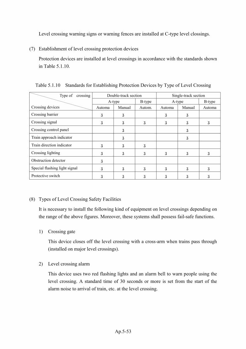
Ap.5-53
Level crossing warning signs or warning fences are installed at C-type level clossings.
(7) Establishment of level crossing protection devices
Protection devices are installed at level crossings in accordance with the standards shown
in Table 5.1.10.
Table 5.1.10 Standards for Establishing Protection Devices by Type of Level Crossing
Double-track section Single-track section
A-type B-type A-type B-type
Type of crossing
Crossing devices Automa Manual Autom. Automa Manual Automa
Crossing barrier 〇 〇 〇 〇
Crossing signal 〇 〇 〇 〇 〇 〇
Crossing control panel 〇 〇
Train approach indicator 〇 〇
Train direction indicator 〇 〇 〇
Crossing lighting 〇 〇 〇 〇 〇 〇
Obstruction detector 〇
Special flashing light signal 〇 〇 〇 〇 〇 〇
Protective switch 〇 〇 〇 〇 〇 〇
(8) Types of Level Crossing Safety Facilities
It is necessary to install the following kind of equipment on level crossings depending on
the range of the above figures. Moreover, these systems shall possess fail-safe functions.
1) Crossing gate
This device closes off the level crossing with a cross-arm when trains pass through
(installed on major level crossings).
2) Level crossing alarm
This device uses two red flashing lights and an alarm bell to warn people using the
level crossing. A standard time of 30 seconds or more is set from the start of the
alarm noise to arrival of train, etc. at the level crossing.
Ap.5-54
3) Warning bell
This device uses an alarm to warn level crossing users that the crossing gate is about
to come down.
4) Train approach display
This device uses a display light and alarm to indicate the approach of trains, etc. to
level crossing personnel.
5) Train direction indicator
This device shows the direction in which trains are moving (level crossings which
span two or more lines).
6) Level crossing obstruction warning device
In cases where it is necessary to protect the level crossing such as times when
vehicles stop inside the crossing, etc., one of the following devices is installed in
order to indicate stop signals to trains, etc.
① Red light flash device and protection switch to operate this (track circuit shall
also be shorted and related signals shall show the stop aspect too).
② Obstruction detection device
Protection switch and fusee (the fusee burns by handling of the protection
switch by a pedestrian)
7) Obstruction detection system
This system detects obstructions on the level crossing and automatically activates
the railway crossing obstruction warning device. This system is mainly installed on
unmanned level crossings on double track sections.
8) Other
On level crossings, it is necessary to install warning markers and lights, etc. to
inform passers-by that a level crossing exists there.

Ap.5-55
6.8 Communication System for Safety Purposes
A communication system for safety shall be installed between such facilities as stations
and so forth, substations, operation command center and power command office, etc. for
safety and operational purposes.
(1) Exclusive telephone lines shall be installed between station control rooms, substations
and other facilities which are directly related to train operation.
(2) In particular, on underground and elevated railways, communication systems which
enable direct communication shall be installed between trains and related facilities such
as operation and power command posts, etc.
6.9 Installation of Communication Cables
Overhead communication cables shall be installed at a sufficient clearance/distance so as
not to disrupt other means of transport and shall not contact power cables in order to
avoid any physical harm to persons.
(1) Height of Overhead Communications Lines
1) When crossing over railways, the standard height of communication lines shall be 6
m or more.
2) When crossing over roads, the standard height of communication lines shall be 5 m
or more. These standards shall be separately relaxed in special sites.
(2) At telephone installation points connected to overhead communications lines, safety
facilities to counter mixing with other telephone lines and lightning strikes, etc. shall be
installed.
Chapter 7 Rolling Stock
7.1 Size Limits of Rolling Stock
Rolling stock shall not exceed the specified size limits of rolling stock.

Ap.5-56
(1) Rolling stock shall not exceed the specified size limits.
1) However, for each of the items enumerated in Table 5.1.11, the size limits for rolling
stock may be exceeded as long as the conditions stipulated for each are satisfied.
Table 5.1.11 Devices that can exceed rolling stock size limits
No. Device Condition
1 Wheels, auxiliary pilot & rail inundationdevices
Must be within construction sizelimits
2 Doors Must be opened
3 Cranes & similar items Must be in use
2) “Rolling stock shall not exceed the specified size limits” means that rolling stock
(including that with wheel friction) stops on an even, straight rail with the center line
of the car body and bogie matching the center line of the rail, and that with loading
done from an empty car to the maximum load that can be applied, the inclination of
passengers or loaded items does not cause the car body and bogie to tilt.
3) In this case, “maximum load” means the total of the maximum no. of people that can
ride in a passenger car (the train crew, nominal passenger seating capacity and
maximum standing capacity; this figure is obtained by dividing the area for the
passenger floor space -- excluding 100 mm from the front edge of seats and
including the area of effective width of 300 mm or more and effective height of
1,800 mm that can be secured -- by 0.1m2, with decimal places rounded off).
4) However, for rolling stock that does not accommodate anything above the seating
capacity, this is the load resulting from the total of passenger capacity and crew. For
freight cars, this is the maximum loaded weight. The weight per person shall be
taken to be 55 kg.
5) Nominal passenger seating capacity is the figure derived by dividing seat width by
the length occupied per person. The length shall be over 430 mm, as a rule.
6) Standing capacity is the figure arrived at by dividing the area of passenger floor
space -- excluding 250 mm for seats and the front edge of seats and including the
area of effective width of 550 mm or more and effective height of 1,900 mm or
more -- by the width occupied per passenger. The width occupied per passenger
shall be taken to be 0.3 m2, as a rule.


Ap.5-58
(3) For the size limits for rolling stock on a curved track, an appropriate number shall be
added to each side of the size limits for rolling stock on a straight track, in accordance
with the rolling stock’s inclination, and with the slant that accompanies cant. The
appropriate number to be added for a curved track can be derived using the following
formula.
W=22,500/R.............................................................(7.1.3.a)
W:Number that must be added (unit: mm)
R:Radius of curved track (unit: m)
(4) Sizes of car bodies
For the sizes of car bodies, consider the information provided in Table 5.1.12.
Table 5.1.12 Sizes of Car Bodies
No. Line Features Size of car body
1 General new line
Car body size should be determined in keeping with current & futurepassenger demand, fixed regulations for rolling stock, curved track, etc.,of the lines used.
Considering only passenger capacity, as there is no major difference in thebogies & devices for large rolling stock, manufacturing costs per unit ortransport will be reduced.
2General new subwayline
If the car body is long, inclination on curved tracks will be higher, whichwill rebound in tunnel construction expense.
Generally, the length of rolling stock is 18-20m & the width 2.8-2.9m.Although height doesn’t directly relate to passenger capacity, inconsideration of the reciprocal relations of wheel diameter, rooftopdevices & fixed regulations for rolling stock, the bigger the size, the betterit is for passenger service. For underground service only, with the 3rd-railcurrent-collecting system, construction costs can be lower than for thepantograph type, as the lack of rooftop devices on rolling stock permitslower tunnel height.
3New line expected toprovide direct service onexisting line
Rolling stock should be the same size as that operating on the existingline. If sizes differ owing to the existence of multiple lines, a size &weight that can run on all of them should be adopted.
4Subway line expected toprovide direct service onexisting line
Rolling stock having the same current-collecting system, size, and weightof that used on the existing line should be used. For power generatingequipment, electric types should be used.
5Existing line expected toprovide direct service
Rolling stock that will provide direct service on different-size routesshould be newly manufactured at a size and weight that can run on all ofthem should be adopted.

Ap.5-59
(5) Correlation of inclination of car body and radius of curved track
Fig. 5.1.30 illustrates the correlation between the inclination of a car body inclination and
the radius of a curved track.
Fig. 5.1.30 Correlation of Car Body Inclination and Radius of Curved Track
Legend
l : Distance between bogie centers
L: Outside length of car body
R: Radius of curved track
x: Center inclination of rolling stock
y: Inclination at both ends of rolling stock
R2 = (R – x )2 + ( l /2)2
x ≒ l 2 / 8R ------------------------------------ (7.1.5.a)
( R + y )2 = ( R – x )2 + ( L / 2)2
y ≒ ( L2 - l 2 )/8R ----------------------------- (7.1.5.b)
Next, if x = y,
L ≒ 2 l ---------------------------------- (7.1.5.c)
Considering inclination alone, a distance between bogie centers that is 1/ 2 of the
length of the rolling stock is appropriate.
L
l
R
x
y

Ap.5-60
7.2 Constraints with respect to Tracks and Structures
Rolling stock shall not impose a heavier burden than that bearable by tracks and
structures.
(1) Weight of loaded car
Weight of loaded car refers to the weight of the following: the rolling stock loaded with the
full weight of the fuel, lubricating oil, cooling water, etc., for the motors and fuel devices
(for a steam locomotive, 1/2 the weight); the provision of fixed equipment necessary to the
purpose of the relevant rolling stock, along with the equipment necessary for operation;
crew members of a number appropriate for the onboard facilities for the crew of the
relevant rolling stock are on board; passengers of a number appropriate to the passenger
capacity are on board; and the goods comprising the maximum loaded weight (for surface
inscriptions, the unit should be tons, rounded off after the second decimal place).
In this case, the weight per crewmember and per passenger shall be taken to be 55 kg.
(2) Tare weight
Tare weight refers to the loaded weight in the previous paragraph, minus the weight of the
crewmembers, passengers and goods (for surface inscriptions, the unit should be tons,
rounded off after the second decimal place).
(3) Materials
For car-body body-structure materials, ordinary steel, stainless steel and light alloys are
used.
1) Car bodies made from ordinary steel
In general, car bodies made from ordinary steel are painted and those made from
stainless steel or light alloys are not. Paint fulfills the roles of preventing rust and
providing color for rolling stock or routes. Paint service life is ordinarily 2 to 3 years.
Repainting will deteriorate the operating rate of rolling stock, necessitate paint factory
facility costs and paint work expense, and entail the obligation of protecting workers
from the organic solvents used in paint. For these reasons, the rationality of painting
versus not painting was investigated.
2) Car bodies made from stainless steel or light alloys
Although stainless steel and light alloys are expensive, economic comparison of
unpainted cars with ordinary steel cars reveals that stainless cars and light-alloy cars
become more economical (after around 1.5 years for the former and 7.5 years for the
latter) than ordinary steel cars. However, skin stainless steel cars were used for this
comparison.
① Stainless steel cars

Ap.5-61
a) History of stainless steel cars
In 1934, America’s Budd Co. supplied the Barrington Railroad with a diesel car
for a special express train with 3-car articulated structure, which was the
world’s first stainless steel car. Their aim was to make car lighter and faster
than steel rolling stock. Nicknamed “Zephyr No. 1,” the car was active in the
Chicago area. In 1958, Japan’s Tokyu Corporation purchased the “DEHA
Model 5200,” a 3-car train set, from Tokyu Car Corp.
b) Objective for adopting stainless steel
As stainless steel cars do not rust, they are strong left unpainted, permitting thin
materials to be used. They are useful for making rolling stock light, reducing
electricity fees used in operation, route maintenance fees and the ratio of motor
cars, while making it possible to improve operating efficiency through high
acceleration and high deceleration.
As they do not need to be painted, maintenance time at maintenance factories is
reduced and painting facilities become unnecessary, along with the noxious
substances contained in paint.
Shortcomings that can be cited are the difficulty of stainless steel processing and
high initial cost.
② Aluminum alloy cars
a) History
In 1896, France’s Northern Railway which is currently the national railway,
adopted, on a trial basis, aluminum for the window frames of its passenger cars.
In 1905, England’s Lancashire and Yorkshire Railway(currently the national
Fig. 5.1.31 Stainless Steel Rolling Stock
The 209-series commuter trains of East Japan Railway Co., featuresleek stainless steel bodies, reliable safety equipment, and inductionmotors, which require minimum maintenance.

Ap.5-62
railway)found that at the time of electrification, the high overhead lines within
the city of Liverpool made lighter rolling stock a necessity. It thus adopted
aluminum alloy for motorcars’ outside plates and built-in parts.
From 1923 to 1932, America’s Illinois Central Railroad, Chicago and
Northwestern Railroad and the like adopted aluminum alloy for the outside
plates, rooftop panels, etc., of nearly 700 passenger cars. In 1933, the Union
Pacific Railroad manufactured on a trial basis a 3-car-set streamlined diesel
special express train, “City of Selena.”
With modernization and rationalization as its goals, the London Underground
spent seven years (1945 to 1952) developing aluminum rolling stock. In 1954,
Canada’s Toronto Subway began adopting it, as did, in the 1960’s, West
Germany’s Cologne and Bonn Railway in the 1960’s, for its suburban trains. In
1962, Japan’s Sanyo Electric Railroad introduced West Germany’s technology
in its adoption of all-aluminum trains.
b) Objective for adopting aluminum alloy cars
Because the aluminum alloy cars of the rolling stock of long-distance railways,
which have the mission of linking cities in a short time, are lightweight,
improvement of maximum speed is aimed for.
High-speed urban railways, centering on subways, can plan to improve
acceleration speed, shortening arrival times and reducing the number of trains
run. Doing so will lead to lower expense for manufacturing new rolling stock,
decreased scale of tram depots and rolling stock maintenance factories, and
reduced land.
In addition, if the size of such rolling stock is the same as that made of steel,
electric power fees can also be saved. Bogies, traction motors, and gear units
can be miniaturized. The strength of bridges and rails can be reduced. The
service lives of rolling stock and rails will increase. The capacity of substations
and transmission and supply lines can be lowered. For subways, the quantity of
heat generated in tunnels can be reduced.
Aluminum is expensive, and unpainted car bodies are easily soiled and hard to
clean. A damaged car body requires expertise to repair.

Ap.5-63
(4) Weight of body structure
1) Skin stainless cars
To make skin stainless cars unpainted, only the shell is made out of stainless steel, and
the other parts of the body structure are made of ordinary steel. Such car bodies do not
differ greatly strength-wise from those made of ordinary steel, and their weight is also
the same.
2) All-stainless-steel cars
With all-stainless-steel cars, because stainless steel’s tensile strength is about 3 times
that of ordinary steel, the weight of the body structure can be lightened around 20%
while maintaining the same strength. All-stainless-steel cars have lower material costs
than light alloys, and as they can be made lighter than cars made of ordinary steel, they
continue to replace them.
Fig. 5.1.32 Aluminum alloy Rolling Stock
07 series subway rolling stock of Yurakucho Line, TRTA, Tokyo, in the body
workshop

Ap.5-64
3) Aluminum cars
Although aluminum cars have nearly the same tensile strength as cars made out of
ordinary steel, they are light and do not easily corrode. In terms of aluminum’s
workability, progress has been made in material extrusion technology and soldering
technology. Thus, strong, light aluminum cars can now be manufactured cheaply,
relative to the high price of the materials. Particularly with friction stir welding (FSW),
which uses the molding fluidity from friction heat against side body structures, any
distortions in assembled car bodies are very difficult to perceived, making beautiful car
bodies possible -- even unpainted. Because aluminum cars make the volume of
electricity used for running cheap, economic comparison with skin stainless steel cars
reveals that the superiority of aluminum cars is recognized in about 16 years. When their
designs become outdated, aluminum cars can easily be recycled. In recent years, these
results have been observed in Tokyo’s subway. In addition, aluminum materials in
which the use of zinc is curbed have evolved, in consideration of recycling.
Fig. 5.1.33 Aluminum Alloy Rolling Stock
02 series subway rolling stock, which has collector shoes for third rail system,Marunouchi Line, TRTA, Tokyo.

Ap.5-65
(5) Advantages of reducing the weight of rolling stock
1) Reduced electric power costs for operation. Also, if electric power costs are left the
same, increased transport volume is possible.
2) Smaller ground electric power facilities.
3) Smaller rolling stock devices.
4) Reduced burden on rails.
7.3 Stability
Rolling stock shall be capable of providing a stable running
performance under the anticipated conditions.
Rolling stock must have a structure that prevents it from over-turning when stopped on a
curved track with a cant.
7.4 Running Gear
7.4.1 Running gear shall be solid with sufficient strength, shall be capable of ensuring
the safe as well as stable running of rolling stock and shall not damage the track.
Bogie
The bogie runs under the load of the car body and is mounted with a traction motor, driving
gear and foundation brake gear. In addition to shock load from the rail, it is subjected to the
reverse force of the traction motor and driving gear; thus, it must be designed and
manufactured with safety sufficiently considered.


Ap.5-68
(1) Bogie Frame
In general, the bogie frame is a lightweight structure high tensile steel or ordinary steel
that has been welded into a box shape. It is composed of side beams, crossbeams, end
beams (in some cases, end beams do not exist.) Mounted in the bogie frame are a swing
bolster device (called a bolster; in some cases, bolsters do not exist), axle box suspension,
traction motor installation seat, driving gear suspended seat, and foundation brake gear. In
addition, for third-rail systems there is an insulated beam for mounting the current
collecting device, which comes installed in the axle box.
(2) Air Spring
As a bolster spring of the secondary suspension gear, the air spring receives the load of
the car body, absorbing noise and vibration. As the air spring makes for a comfortable
ride, it is adopted for much railway rolling stock, as well as subway rolling stock. The air
spring is equipped with an automatic level-controlling valve that enables it to maintain
uniform height irrespective of the load.
In terms of air springs, there are systems used by the swing bolster device and systems
used directly between bogie frames. Systems that do not use the swing bolster device are
called “bolsterless bogies.”
Although the bolsterless bogie makes for a comfortable ride and has superior
maintainability, when wheel load control is poor, the derailment coefficient may increase
at low speeds.
Fig. 5.1.36 Bolsterless bogie
07 series subway rolling stock of Yurakucho Line, TRTA, Tokyo

Ap.5-69
(3) Axle box suspension
The coil spring is used as a primary suspension gear. The most common axle box and
bogie side frame suspension systems are the link type and the pedestal type. Optimally,
systems should have low vibration, noise and friction. In addition, linear parts must be
able to run smoothly run sharply curved tracks without hunting.
(4) Wheels
Types of wheel include the tire wheel and the solid rolled wheel.
1) Tire wheels
① The tire wheel makes for a comfortable ride.
② It is inexpensive.
③ When the tire is heated, it fits into the wheel center; thus, continuous use of the
brake raises the possibility of tire loosing, making this wheel inferior to the solid
rolled wheel in terms of reliability.
2) Solid rolled wheels
① The solid rolled wheel results in no heat-induced tire loosing, giving it excellent
reliability.
② The most common usage limit for the wheel is a diameter of 10 mm, making longer-
term use than tire wheels possible.
③ Its mono-bloc structure means there is little electric resistance.
④ As the solid rolled wheel fits directly into the axle, it shortens the axle’s service life.
⑤ Through rim quenching, the solid rolled wheel permits surface hardness. The harder
the surface, the better anti-friction performance is. However, surface peeling may
result from skids and the high temperature of the rim brake.
3) Noise Damped Wheel
Although noise damped wheels exist, reliability must be given first priority in
selecting a noise damping system.
(5) Axle
The axle fatigue safety rate can be determined using the following formula. Optimally,
the safety rate will be 1.2 or more.
Legend
b: Bending stress from external force
Wb: Fatigue limit for bending stress only
τ: Twisting stress from external force
τe : Elasticity when twisting stress only is applied
(6 b / 6 W b )2 + ( τ/τe )2
1Fatigue safety rate = ------ (7.4.1.5.a)
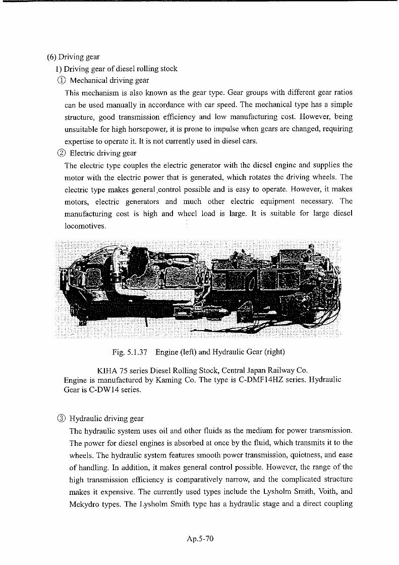

Ap.5-71
stage. Its high speed-ratio depends on the direct coupling. The Voith type is equipped
with multiple converter and coupling elements. The type with the highest efficiency in
accordance with car speed can be selected for use. For example, when the speed ratio is
low, the torque converter can be supplied with oil and the oil from the hydraulic
coupling drained. When the speed-ratio becomes high, oil can be added to the
hydraulic coupling when the clutch point is passed, and the torque converter can be
drained. The Voith type enables a set number of diesel engine revolutions to be
maintained. This allows the greatest efficiency, no matter what the speed of the rolling
stock, and makes it possible to base operation on the number of revolutions. In terms
of performance, the Voith type is basically the same as an electric transmission system.
The Mekydro type has an overrunning clutch operated via oil pressure and is a
combination of a 4-stage transmission gear (including the reverse mechanism) and one
regular replenishment-type converter. Different from the Voith type, the Mekydro type
has the converter regularly replenished with oil; automatic switching of gear groups
thereafter allows the optimal speed ratio to be maintained. With the Mekydro type,
output suited to rolling stock characteristics over a wide range of car speeds can be
obtained. In other words, high torque for departure and low torque for high speeds can
be obtained. Thus, operation at a high rate of efficiency is always possible.
2) Driving gear of electric rolling stock
As the bogie-mounted traction motor has relative displacement from the pinion axle of
the gear box, a cardan driving device is used. The cardan driving device with flexible
gear coupling and the hollow shaft parallel cardan driving device are general cardan
driving devices.
① Cardan driving device with flexible gear coupling
a)Power transmission is smooth.
b)When the gauge is 1.067m, the dimension in the axial direction of the traction motor
will be restricted.
c)Because frictional parts involve grease, maintenance is somewhat involved.
② Hollow shaft parallel cardan driving device
a)There are no frictional parts and the weight is low.
b)Shock from the rail is reduced with a twisting rod and flexible plate.
c)Because the armature axle is hollow, there are limits to commutator rotation speed
and the number of bearing rotations.
d)It is necessary to be aware of bending damage to the flexible plate.
7.4.2 The distribution of the wheel set of a car shall allow passing of the minimum
radius of the running line without any problems.

Ap.5-72
(1) Arrangement of wheel set
The arrangement of the wheel set shall allow passing of a curved track with a 100m radius,
with slack on the gauge (for a gauge 0.762m railway, a curved track with a 40m radius).
(2) Rigid wheelbase
The rigid wheel base is the level distance between the wheel centers of the wheel set in the
very front and the wheel set in the very back of one unbending bogie frame.
For railways with gauges of 1.067m, 1.372m and 1.435m, the wheelbase must be 4.57m or
less. For railways with a gauge of 0.762m, it must be 3.05m or less.
(3) Wheel diameter
1) Wheel diameter, width of wheel rims (for wheels with tires, tire width; same hereinafter)
and the back gauge for a pair of wheel rims must be as specified in Table 5.1.13.
Table 5.1.13 Wheel diameter (italicized numbers are in accordance with tram law)
Gauge (unit: mm)Item
762 1,067 1,372 1,435
a. Wheel diameter 400 or more 680 or more 680 or more 680 or more
b. Wheel rim widthfrom 102 to 127
(85~ 115)from 120 to 150
(105~ 130) from 120 to 150from 120 to 150
(105~ 130)
c. Back gauge for 1pair of wheel rims
from 695 to 700 from 989 to 994from 1,296 to
1,301from 1,359 to
1,364
d. “d” on the figure 400 560 714 743
Fig. 5.1.38 Wheel Diameter
2) The wheel’s flange height and thickness and the distance from the center line of one
pair of wheels to the flange exterior shall conform to the values given in the above table
Flange height
a
b
Centerline of a pair of wheels
a
b
c
d d