app 4. unsw drafting standards - unsw … 4. unsw drafting standards app 4.1 general the following...
TRANSCRIPT

UNSW DESIGN & CONSTRUCTION REQUIREMENTS 2015
UNSW Drafting Standards ‐ Design & Construction Requirements ‐ Updated July 2015
Page 1 of 14
APP 4. UNSW DRAFTING STANDARDS ................................................. 3
APP 4.1 GENERAL .................................................................................................... 3
APP 4.1.1 Scope ........................................................................................................ 3
APP 4.1.2 Document Transmittal .............................................................................. 3
APP 4.1.3 Drawings ................................................................................................... 4
APP 4.1.4 Operating and Maintenance Manuals ...................................................... 4
APP 4.1.5 Equipment/Asset Schedules ..................................................................... 4
APP 4.1.6 Technical Reports ..................................................................................... 4
APP 4.1.7 Information Requests and Distribution .................................................... 4
APP 4.2 ELECTRONIC MEDIA AND STORAGE ............................................................. 5
APP 4.3 DOCUMENT SUBMISSION ........................................................................... 6
APP 4.4 DRAWINGS REQUIREMENTS ....................................................................... 6
APP 4.5 FILE FORMAT .............................................................................................. 7
APP 4.6 DISCIPLINE SPECIFIC REQUIREMENTS .......................................................... 8
APP 4.7 SURVEY & SITE SERVICES LAYER PROPERTIES TABLE .................................... 9
APP 4.8 SURVEY / SITE SERVICES REQUIREMENTS – LAYERING GENERAL ................. 9
APP 4.9 ARCHITECTURAL LAYER PROPERTIES TABLE .............................................. 10
APP 4.1 ARCHITECTURAL REQUIREMENTS – LAYERING GENERAL ........................... 11
APP 4.2 ARCHITECTURAL ‐ SPACE LAYERS .............................................................. 11
APP 4.3 OPERATING AND MAINTENANCE MANUALS ............................................. 12
APP 4.4 DOCUMENT REGISTER AND TRANSMITTAL – F16 ...................................... 13
APP 4.5 GLOSSARY ................................................................................................. 14

UNSW DESIGN & CONSTRUCTION REQUIREMENTS 2015
UNSW Drafting Standards ‐ Design & Construction Requirements ‐ Updated July 2015
Page 2 of 14
UNSW DRAFTING STANDARDS – SCHEDULE OF CHANGES – June 2015
As a guide only, attention is drawn to changes that have been made in the following clauses since the last revision
Clause DateGeneral revision Changes have been made throughout this document.
Clauses App 4.8 to 4.9 have been relocated to Section B
August 2004
General changes including AutoCAD version, reference
to 3.5 disk removed. Fire compartment details added
December 2006
Changes made throughout document. Separated CAD
standards into disciplines
June 2014
General revision /update site services July 2015
i:\edfo\fm\global\design & construction guidelines\17 ‐ appendix 4 unsw drafting standards july 2015.docx

UNSW DESIGN & CONSTRUCTION REQUIREMENTS 2015
UNSW Drafting Standards ‐ Design & Construction Requirements ‐ Updated July 2015
Page 3 of 14
APP 4. UNSW DRAFTING STANDARDS
APP 4.1 GENERAL
The following requirements form part of the University of New South Wales (UNSW) Design and
Construction Guidelines and outline the minimum acceptable standards for documents submitted by
consultants and contractors for UNSW projects.
APP 4.1.1 Scope
All documents created in relation to work carried out on behalf of UNSW Facilities shall be provided in electronic format for all disciplines and services. Documents shall include:
Drawings
Operating & Maintenance Manuals
Equipment/Asset Schedules
Technical Reports
APP 4.1.2 Document Transmittal
All documents shall be supplied with an accompanying document transmittal. The transmittal shall include details of:
Details of sender
UNSW Project name
Date of issue/rev
Reason for issue
Acknowledgement of receipt
Index/description of each item detailing exactly what has been provided
Supplier Project Name
If the transmittal provided contains insufficient information a Facilities "Document Register and Transmittal" form F16 shall be completed by the sender. Documents will not be accepted until an appropriate transmittal is provided.
Letters identifying drawing disciplines:
A Architectural
S Structural
M Mechanical & Lifts
E Electrical
H Hydraulic
DC Data & Communications
C Civil & Survey
F Fire (including Fire Compartment plans)
CAD files shall follow the UNSW naming standard:
Drawing discipline – Building grid code – floor code E.g. A‐C20‐G (Architectural – Building Code: C20 –
Ground Floor)

UNSW DESIGN & CONSTRUCTION REQUIREMENTS 2015
UNSW Drafting Standards ‐ Design & Construction Requirements ‐ Updated July 2015
Page 4 of 14
APP 4.1.3 Drawings
Drawings are to be provided in Electronic format with drafting work presentation that is in accordance with
Australian Standard AS1100; that is printable to scale, on ISO size sheet which is legible.
Electronic CAD drawings shall be provided in AutoCAD format (minimum version 2010).
The file extension “.dwg” is mandatory.
If additional linked files, being information, or specific software that is contractually inclusively used, eg;
such as Building Information Modeling (BIM) are part of performance documentation, then the native file is
also required as a deliverable.
APP 4.1.4 Operating and Maintenance Manuals
Operating and maintenance manuals shall be provided in electronic format for all disciplines and services as
described in APP 4.1.2. Electronic format copies shall be provided in native files format for each discipline
and combined into a single Adobe PDF file incorporating click‐able navigation hotlinks between the table of
contents and subject headings. Complete manufacturer or supplier catalogue incorporated in a manual may
be incorporated or provided as a separate PDF file as necessary.
The Contractor shall provide three electronic copies of each manual.
APP 4.1.5 Equipment/Asset Schedules
Equipment/asset schedules incorporated in operating and maintenance manuals, specific to the
project/UNSW, shall also be provided in electronic format as a Microsoft Excel spreadsheet. The format of
this spreadsheet shall be consistent with the UNSW Asset Data Template. A copy of this template is
available from the CMMS Administrator on request.
APP 4.1.6 Technical Reports
Technical reports shall be provided in hardcopy and electronic format. Electronic format copies shall be
provided in native files format for each discipline and combined into a single Adobe PDF file incorporating
click‐able navigation hotlinks between the table of contents and subject headings. Complete manufacturer
or supplier catalogue incorporated in a manual may be incorporated or provided as a separate PDF file as
necessary. UNSW Asset Barcode identification shall be included as reference in reports for assets that are
barcoded.
APP 4.1.7 Information Requests and Distribution
All documents shall be forwarded to the responsible Facilities Management Works Supervisor for
distribution to the relevant persons for checking and approval of the content, such as the design, detail,
accuracy and correctness.
Consultants and contractors appointed to carry out work on behalf of the University are requested to
familiarise themselves with the documents prior to preparing designs or documents for new work.
In general existing drawings consist of a mixture of hardcopies, CAD files and raster images. General
enquiries and requests for information shall be directed to the Facilities Management Works Supervisor via
email.

UNSW Dra
All electr
shall not
All disks
All medi
damage.
and scan
DISK TEM
afting Standard
APP 4.2
ronic files sh
t be accepted
submitted s
HeDis
Da
Att
Pro
De
Co
Sup
a submitted
. DVD's shall
nned for viru
MPLATE
UNSW
s ‐ Design & Co
2 ELECT
hall be provid
d
shall be clear
ading sk No:
te:
tention:
oject:
tails:
ntact:
ppler details
for acceptan
be individua
uses prior to
DESIGN & C
onstruction Req
RONIC ME
ded on non‐r
rly labeled to
:
nce shall be
ally boxed. E
dispatch to F
CONSTRUCTIO
quirements ‐
Page 5 of
EDIA AND S
rewritable DV
o display the
Value (Exam1 of 2 etc.
Date of disp
UNSW Rep
Project nam
Disk conten
Name and p
Name of co
enclosed in a
Electronic file
Facilities Ma
ON REQUIRE
f 14
STORAGE
VD disk with
following m
mple)
patch
resentative
me, campus,
nts, files, disc
phone no:
ompany resp
a suitable pr
es and media
nagement.
EMENTS 201
a printed la
inimum deta
building, roo
cipline etc.
onsible for d
rotective cov
a shall be tes
15
Updated
abel. Hand w
ails:
om
delivery
ver to preven
sted for effec
d July 2015
written labels
nt physical
ctive operati
s
on

UNSW DESIGN & CONSTRUCTION REQUIREMENTS 2015
UNSW Drafting Standards ‐ Design & Construction Requirements ‐ Updated July 2015
Page 6 of 14
APP 4.3 DOCUMENT SUBMISSION
Unless otherwise advised all documents shall be submitted in electronically in accordance with the items
specified in these requirements including all Drawings, Operating & Maintenance Manuals,
Equipment/Asset Schedules and Technical Reports for all disciplines and services as required.
The submission of documents for review purposes are to be in an electronic file format that is capable of
being read without editing in compatible software used by the University.
The review documentation deliverables are to be on non‐rewritable DVD unless specified differently in the
contract. Review of work in‐progress files shall be supplied in the following electronic formats:
Document Types File FormatsDrawings dwg, pdfGraphics/Images/Photo’s jpgText/Documents doc, docxSpreadsheets xls,
CAD drawings submitted shall be in AutoCAD format with PDF proofing file readily able to be plotted to a
legible, high quality resolution of standard scales in accordance with AS1100.
ISO size drawing sheets; A4, A3, A2, A1, B1, A0; may be used.
APP 4.4 DRAWINGS REQUIREMENTS
CAD files shall be in AutoCAD drawing (DWG) format. The version required is AutoCAD 2010 or onwards. If
AutoCAD is not the contractor’s primary software CAD files need to be converted to DWG format. Drawings
are to be in 2D format. 3D plans will be accepted separately for future BIM purposes.
The following drawing requirements must be met:
All CAD drawings must be drawn as one continuous and uniform plan in MODEL SPACE. PAPERSPACE should only be used as an outlet for the ability to plot
Plans are to be drawn at a scale of 1:1 Architectural ‐ 1 drawing unit to 1 millimetre in model space Site Services ‐ 1 drawing unit to 1 millimetre in model space
Each CAD drawing file showing building plans is to contain only the plan information for that level. No other plan is to be placed on the drawing
Multiple drawings shall not be permitted on one CAD file
All text, dimensions, drawing reference symbols, hatching and border sheets are to be on separate layers
Text for services to be in the same layer of the service.
Style to be use: UNSW (Arial), Text height 0.350.
All Text services to Include: Service identification, Diameter and Material, Example: FSØ100Cu (Fire service, (%%c)100mm Pipe in cooper)
UNSW Layers must be used as outline in discipline CAD standards – refer to App 4.7 & 4.10
UNSW Plot Style Tables (.ctb) files will be supplied and must be used
No external references (x‐refs) to be used on main drawing (If x‐refs exist, they are to be bound and delivered separately)
All drawings shall be purged
All AutoCAD files (plans) must have the base reference set to “0,0,0”.
Revit Drawings shall be prepared at UNSW Revit version. Consult UNSW FM CAD staff for further information on Revit Version.

UNSW DESIGN & CONSTRUCTION REQUIREMENTS 2015
UNSW Drafting Standards ‐ Design & Construction Requirements ‐ Updated July 2015
Page 7 of 14
Revit Drawings shall be converted to AutoCAD format with all layers as per UNSW specifications.
All entities in the drawing file must have the colours and line types set to BYLAYER.
Blocks may be used: Any identical group of entities, objects or symbols in a drawing shall be removed.
All CAD files are to be accompanied by the corresponding PDF drawing
All CAD files shall be purged of any unused blocks, fonts, layers, line types, external reference files, objects, images and any non‐relevant line work etc. and zoomed to the drawing extents prior to submission.
APP 4.5 FILE FORMAT
CAD files shall be in AutoCAD drawing (DWG) format
The version required is to be no later than AutoCAD 2010
If AutoCAD is not the contractor’s primary software CAD files need to be converted to DWG format delivering UNSW layers attributes.
Drawings are to be in 2D format

UNSW DESIGN & CONSTRUCTION REQUIREMENTS 2015
UNSW Drafting Standards ‐ Design & Construction Requirements ‐ Updated July 2015
Page 8 of 14
APP 4.6 DISCIPLINE SPECIFIC REQUIREMENTS
External plans, Site Surveys & As‐Constructed Services, drawings shall include the following:
Item What to include Survey Architectural Site Services
Buildings
Footprints Basements Facades Awnings Overhangs External Columns Steps & Building Thresholds
X X X
Hardstand Areas
Concrete‐trafficable or footpath Paving‐trafficable or footpath Paving Type:‐
Terrazzo/Brick/Sandstone/Exposed Aggregate/Pervious Paving
Bitumen‐trafficable or footpath
X
Roads Kerb & Gutters Car Parking Bays Stormwater Pits (Inverts/Pipe sizes)
X X X
Spot Levels Australian Height Datum (AHD) Contours at appropriate intervals
X X X
Trees Showing Trunk ɸ / Spread / Height (Trunks greater than 100mm & 3m in height)
X X
Services Any visible service, pit and/or box X X
Services as constructed
New services by layer Services identifiers (pipe, size & Material) Invert levels Services structures
X
Disused Services
All disused services by Layer Services identifiers (pipe, size & Material) Disused Services structure
X
Features
Garbage Bins Seating Benches Fixed Tables Bollards
X X X
Landscape
Retaining Walls Gardens/Lawns Top & Toe of banks Statues Fountains
X X X
UNSW DESIGN & CONSTRUCTION REQUIREMENTS 2015
UNSW Drafting Standards ‐ Design & Construction Requirements ‐ Updated July 2015
Page 9 of 14
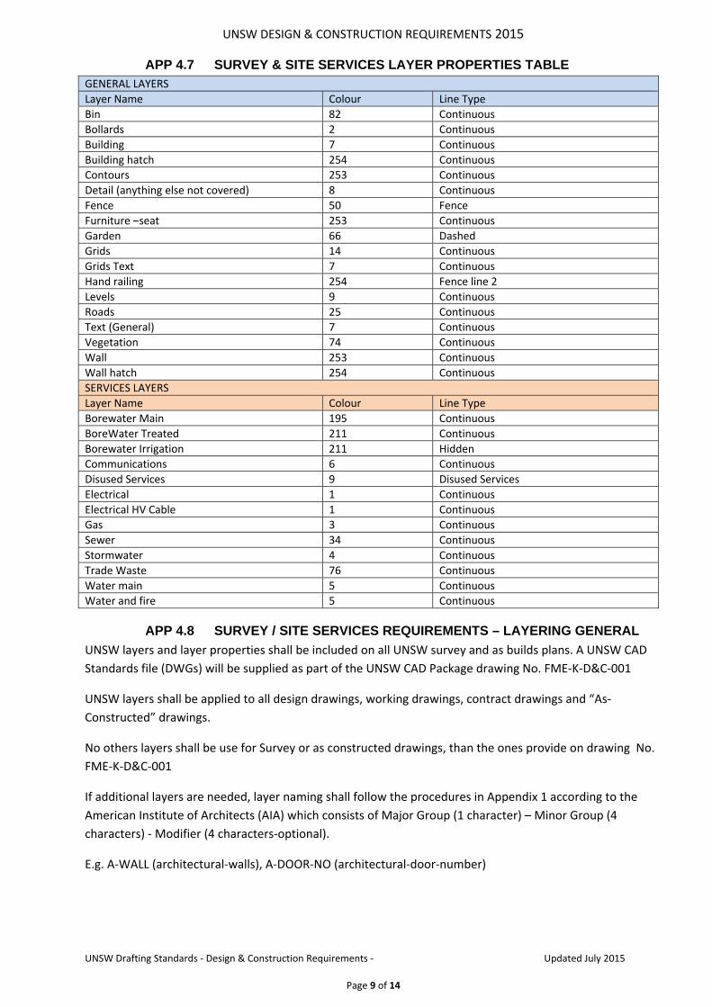
APP 4.7 SURVEY & SITE SERVICES LAYER PROPERTIES TABLE
GENERAL LAYERS
Layer Name Colour Line Type
Bin 82 Continuous
Bollards 2 Continuous
Building 7 Continuous
Building hatch 254 Continuous
Contours 253 Continuous
Detail (anything else not covered) 8 Continuous
Fence 50 Fence
Furniture –seat 253 Continuous
Garden 66 Dashed
Grids 14 Continuous
Grids Text 7 Continuous
Hand railing 254 Fence line 2
Levels 9 Continuous
Roads 25 Continuous
Text (General) 7 Continuous
Vegetation 74 Continuous
Wall 253 Continuous
Wall hatch 254 Continuous
SERVICES LAYERS
Layer Name Colour Line Type
Borewater Main 195 Continuous
BoreWater Treated 211 Continuous
Borewater Irrigation 211 Hidden
Communications 6 Continuous
Disused Services 9 Disused Services
Electrical 1 Continuous
Electrical HV Cable 1 Continuous
Gas 3 Continuous
Sewer 34 Continuous
Stormwater 4 Continuous
Trade Waste 76 Continuous
Water main 5 Continuous
Water and fire 5 Continuous
APP 4.8 SURVEY / SITE SERVICES REQUIREMENTS – LAYERING GENERAL
UNSW layers and layer properties shall be included on all UNSW survey and as builds plans. A UNSW CAD
Standards file (DWGs) will be supplied as part of the UNSW CAD Package drawing No. FME‐K‐D&C‐001
UNSW layers shall be applied to all design drawings, working drawings, contract drawings and “As‐
Constructed” drawings.
No others layers shall be use for Survey or as constructed drawings, than the ones provide on drawing No.
FME‐K‐D&C‐001
If additional layers are needed, layer naming shall follow the procedures in Appendix 1 according to the
American Institute of Architects (AIA) which consists of Major Group (1 character) – Minor Group (4
characters) ‐ Modifier (4 characters‐optional).
E.g. A‐WALL (architectural‐walls), A‐DOOR‐NO (architectural‐door‐number)

UNSW DESIGN & CONSTRUCTION REQUIREMENTS 2015
UNSW Drafting Standards ‐ Design & Construction Requirements ‐ Updated July 2015
Page 10 of 14
APP 4.9 ARCHITECTURAL LAYER PROPERTIES TABLE
Name Colour Linetype Line weight Description
0 white CONTINUOUS ByLineWeightDefault Layer 0
A‐ANNO‐DIMS cyan CONTINUOUS ByLineWeightDefault Architectural ‐ Annotation, Dimensions
A‐ANNO‐LEGN cyan CONTINUOUS ByLineWeightDefault Architectural ‐ Annotation, Legends, Symbol keys
A‐ANNO‐TEXT cyan CONTINUOUS ByLineWeightDefault Architectural ‐ Annotation, Text
A‐ANNO‐TTLB cyan CONTINUOUS ByLineWeightDefault Architectural ‐ Annotation, Border and title block
A‐AREA‐PATT white CONTINUOUS ByLineWeightDefault Architectural ‐ Texture or hatch patterns
A‐CLNG white CONTINUOUS ByLineWeightDefault Architectural ‐ Ceiling
A‐COLS green CONTINUOUS ByLineWeightDefault A‐COLS
A‐DOOR 150 CONTINUOUS ByLineWeightDefault Architectural ‐ Doors
A‐EQPM red CONTINUOUS ByLineWeightDefault Architectural ‐ Equipment
A‐FLOR‐EVTR 10 CONTINUOUS ByLineWeightDefault Architectural ‐ Floor, Elevator cars and equipment
A‐FLOR‐HRAL 10 CONTINUOUS ByLineWeightDefault Architectural ‐ Floor, Handrails, guard rails
A‐FLOR‐STRS 10 CONTINUOUS ByLineWeightDefault Architectural ‐ Floor, Stair treads, escalators, ladders
A‐FURN 242 CONTINUOUS ByLineWeightDefault Architectural ‐ Furniture
A‐GLAZ 92 CONTINUOUS ByLineWeightDefault Architectural ‐ Glazing
A‐ROOF red CONTINUOUS ByLineWeightDefault Architectural ‐ Roof
A‐WALL 50 CONTINUOUS ByLineWeightDefault Architectural ‐ Walls
A‐WALL‐MOVE 50 CONTINUOUS ByLineWeightDefault Architectural ‐ Walls, Moveable equipment
A‐WALL‐PATT 32 CONTINUOUS ByLineWeightDefault Architectural ‐ Walls, Texture or hatch patterns
Name Colour Linetype Line weight Description
S‐SITE‐WALL 50 CONTINUOUS ByLineWeightDefault Structural ‐ Site plan, Walls
S‐WALL yellow CONTINUOUS ByLineWeightDefault Structural ‐ Walls
SPACE‐GBA blue CONTINUOUS ByLineWeightDefault UNSW Space ‐Gross Building Area
SPACE‐GFA cyan CONTINUOUS ByLineWeightDefault UNSW Space ‐ Gross Floor Area
SPACE‐ROOM green CONTINUOUS ByLineWeightDefault UNSW Space ‐ Net Room Area
SPACE‐ROOM‐AREA 255 CONTINUOUS ByLineWeightDefault UNSW Space ‐Gross Building Area
SPACE‐ROOM‐NO yellow CONTINUOUS ByLineWeightDefault UNSW Space ‐Gross Building Area
SPACE‐UCA magenta CONTINUOUS ByLineWeightDefault UNSW Space ‐ Unenclosed Covered Area

UNSW DESIGN & CONSTRUCTION REQUIREMENTS 2015
UNSW Drafting Standards ‐ Design & Construction Requirements ‐ Updated July 2015
Page 11 of 14
APP 4.1 ARCHITECTURAL REQUIREMENTS – LAYERING GENERAL
UNSW layers and layer properties shall be included on all UNSW architectural plans. A UNSW CAD
Standards file (DWGs) will be supplied as part of the UNSW CAD Package .
UNSW layers shall be applied to all design drawings, working drawings, contract drawings and “As‐
Constructed” drawings.
APP 4.2 ARCHITECTURAL - SPACE LAYERS
In addition to building information, space information is recorded on UNSW CAD plans. This includes room
areas, GBA, GFA and UCA. Closed polylines shall be used to define these areas as outlined in Appendix 2.
Polylines determining UNSW Space shall be placed on the corresponding SPACE‐ layer as outlined in table
below:
Name Layer Name Definition
Gross Building Area (GBA) Space‐GBA Measured from the outside face of exterior walls including any projections such as columns.
Gross Floor Area (GFA) Space‐GFA Measured from the inside face of the exterior walls including minor projections such as columns. This total is the sum of FECA (Fully Enclosed Covered Area) and UCA (Unenclosed Covered Area).
Unenclosed Covered Area (UCA) Space‐UCA Measured between the exterior wall and balustrade, edge of paving or cover (roof or upper roof). UCA includes any trafficable uncovered and unenclosed areas such as verandas, balconies, under crofts, car parking stations and attached covered walkways.
Net Room Area Space‐Room Measured from the inside face of a room or space excluding structural projections such as columns which cannot be useable.
Space Room No. Space Room No Displays the room number of a room or a space
Space Room Area Space Room Area Displays the area of a room or a space
Name Colour Linetype Line weight Description
DEFPOINTS white CONTINUOUS ByLineWeightDefault DEFPOINTS
E‐COMM white CONTINUOUS ByLineWeightDefault Electrical ‐ Communications
E‐LITE white CONTINUOUS ByLineWeightDefault Electrical ‐ Lighting fixtures
E‐LITE‐CLNG white CONTINUOUS ByLineWeightDefault Electrical ‐ Lighting fixtures, Ceiling
E‐POWR white CONTINUOUS ByLineWeightDefault Electrical ‐ Major ‐POWR
F‐CO2S‐EQPM white CONTINUOUS ByLineWeightDefault Fire ‐ Equipment CO2
H‐HYD white CONTINUOUS ByLineWeightDefault Hydraulic
I‐FURN‐CASE 242 CONTINUOUS ByLineWeightDefault Interiors ‐ Furnishings, Casework
M‐EXHS‐DUCT white CONTINUOUS ByLineWeightDefault Mechanical ‐ Major ‐EXHS, Minor 1 ‐DUCT
M‐FUME‐EQPM white CONTINUOUS ByLineWeightDefault Mechanical ‐ Major ‐FUME, Equipment
M‐HVAC‐DUCT white CONTINUOUS ByLineWeightDefault Mechanical ‐ HVAC, Minor 1 ‐DUCT

UNSW DESIGN & CONSTRUCTION REQUIREMENTS 2015
UNSW Drafting Standards ‐ Design & Construction Requirements ‐ Updated July 2015
Page 12 of 14
APP 4.3 OPERATING AND MAINTENANCE MANUALS
Operating and Maintenance Manuals shall be created with a view to addressing operating and
maintenance requirements for all disciplines and services including architectural, structural, electrical,
mechanical, hydraulic, fire, communications and essential services
Each manual shall include but not be limited to the following items:
a) A contents index complete with subject headings. b) Details of all consultants, project managers, contractors and subcontractors. c) A comprehensive system description including drawings or diagrams for clarification purposes,
as required. d) Operating and maintenance instructions for all plant and equipment including plant faults and
failures. e) Full details of commissioning, testing, and balancing reports, certificates and warranties. f) Manufacturer and supplier information with the installed equipment clearly identified g) A register of all maintainable plant and fittings including description, type, make, model, serial
no, location, area served and frequency of cleaning and replacement. (Also to be provided separately in electronic format as a Microsoft Excel spreadsheet in accordance with 4.1.5).
h) Shop drawings, schematic diagrams, wiring diagrams, design data, performance curves, control system details, flow rates, methods of control, measuring and control instruments and their locations, schedules of settings for all control and alarm devices, inputs and outputs to BAS etc
i) As‐built drawings shall be provided in accordance with the standards specified in this document; however hardcopy drawings need not be incorporated in the electronic manual so long as they are provided within the manual.

UNSW DESIGN & CONSTRUCTION REQUIREMENTS 2015
UNSW Drafting Standards ‐ Design & Construction Requirements ‐ Updated July 2015
Page 13 of 14
APP 4.4 DOCUMENT REGISTER AND TRANSMITTAL – F16
TO ATTENTION FROM DATE
PROJECT NAME BUILDING/CAMPUS JOB NO:
DISCIPLINE ISSUE/REVISION/DATE
Survey/Civil Architectural Structural Day
Electrical Mechanical Hydraulic Month
Fire Lift Other Year
TITLE/DESCRIPTION NUMBER REVISION
DISTRIBUTION ATTENTION NUMBER OF COPIES
MEDIA/PURPOSE/DELIVERY
P=Print, T=Transparency, CD=Compact Disk, D=Disk, ZD=ZIP Disk
A=Approval, C=Construction, I=Information, T=Tender, X=As-built/installed
C=Courier, E=Email, H=Hand Delivered, M=Mail, P=Pick-up
DISCLAIMER
Documents created by The University of New South Wales (UNSW) remain the property of UNSW as does any media issued. All data files have been checked and confirmed as being virus free prior to issue. UNSW does not accept any liability for any damage or disruption to the recipients computer system or any resident files as a result of the use of any files provided.
(Received Name) (Signature) (Date)

UNSW DESIGN & CONSTRUCTION REQUIREMENTS 2015
UNSW Drafting Standards ‐ Design & Construction Requirements ‐ Updated July 2015
Page 14 of 14
APP 4.5 GLOSSARY
Expression Definition
AS100 Australian Standards for Technical Drawing
AutoCAD 2010 Preferred CAD program
Block A generic term for one or more AutoCAD objects that are combined to create a single object
Bylayer A special object property used to specify that the object inherits the colour or linetype associated with its layer
CAD Computer Aided Drawing (Design/Drafting)
DGN Standard file format for saving vector graphics from within the Microstation CAD program
DOC Standard file format for saving documents from within the Microsoft Word program
DWF For Drawing Web Format. A highly compressed file format that is created from a DWG file
DWG Standard file format for saving vector graphics from within AutoCAD
DXF For Drawing Interchange Format. An ASCII or binary file format of an AutoCAD drawing file for exporting AutoCAD drawings to other applications or for importing drawing from other applications.
Drawing Extents The smallest rectangle that contains all objects in a drawing, positioned on the screen to display the largest possible view of all objects. (ZOOM)
FFL Finished floor Level
FIC Facilities Information Centre (located in Building B13 on the Kensington campus)
HP2 Plot file format for saving vector graphics from withinAutoCAD.
ISO For International Standards Organization. The organization that sets international standards in all fields except electrical and electronics.
JPG (JPEG) Joint Photographics Expert Group standard file format.
Layout The tabbed environment, in which paperspace floating viewports are created, designed and plotted.
Linetype How a line or type of curve is displayed.
Lineweight A width value that can be assigned to all graphical objects except truetype fonts and raster images.
Model space One of the two primary spaces in which AutoCAD objects reside. Typically, a geometric model is placed in a three‐dimensional coordinate space called model space. A final layout of specific views and annotations of this model is placed in paper space
Native File Format
Native file format refers to the default file format that an application uses to create or save files. For example Word and Excel files
Object One or more AutoCAD graphical elements, such as text, dimensions, lines, circles or polylines, treated as a single element for creation, manipulation and modification. Also called entity.
Object Snap mode
Methods for selecting commonly needed points on an object while you create or edit an AutoCAD drawing
Paper space One of the two primary spaces in which AutoCAD objects reside. Paper space is used for creating a finished layout for printing or plotting, as opposed to doing drafting or design work. Paper space viewports are designed using a layout tab
PDF Standard file format for saving documents from within the Adobe Acrobat program
PLT Standard plot file format for saving vector graphics from within AutoCAD.
Raster Raster images consist of a rectangular grid of small squares or dots known as pixels
RL Reduced Level
SMU Space Management Unit
Viewports A bounded area that displays some portion of the model space of a drawing.
XLS Standard file format for saving documents from within the Microsoft Excel program
XREF A drawing file linked (or attached) to another drawing.
Zoom To reduce or increase the apparent magnification of the drawing area.
