api 6d and fire safe - valve & automation · trunnion mounted 3 piece body valves assembly...
TRANSCRIPT
TRUNNION MOUNTED 3 PIECE BODY VALVES ASSEMBLY & MAINTENANCE PROCEDURES REF. DOC.MMM6000E Rev.4 – January 2017
Page 1 of 39
STF STR TRUNNION BALL VALVE SERIES
Manufacturing program:
Quality & Environmental Management:
API 6D and Fire Safe

TRUNNION MOUNTED 3 PIECE BODY VALVES ASSEMBLY & MAINTENANCE PROCEDURES REF. DOC.MMM6000E Rev.4 – January 2017
Page 2 of 39
REVIEW CONTROL
PROCEDURE REF.: DOC.MMM6000E
REV. DATE CARRIED OUT BY APPROVED BY DESCRIPTION
0 24/09/2013 F.Zanuy J. Tejedor First edition
1 03/10/2013 F.Zanuy J.Tejedor General update
2 03/10/2013 F.Zanuy J.Tejedor General update
3 25/11/2013 F.Zanuy J.Tejedor General update
4 12/01/2017 F.Zanuy J.Rubio General update

TRUNNION MOUNTED 3 PIECE BODY VALVES ASSEMBLY & MAINTENANCE PROCEDURES REF. DOC.MMM6000E Rev.4 – January 2017
Page 3 of 39
CONTENTS
1.- APPLICABLE RANGE ................................................................................. Page 4
2.- GENERAL INFORMATION .......................................................................... Page 5
3.- INSPECTION AT RECEPTION AND STORAGE ........................................ Page 6
4.- INSTALLATION ........................................................................................... Page 6
5.- ON-OFF SERVICE …………………...…………………….............................. Page 8
6.- DOUBLE BLOCK & BLEED ….……………………………........................... Page 8
7.- PREVENTIVE MAINTENANCE ................................................................... Page 9
8.- MAINTENANCE OPERATIONS ................................................................. Page 9
9.- REASONS FOR PARTS REPAIR OR REPLACEMENT …..................... Page 10
LEAKAGE THROUGH THE STEM AREA
LEAKAGE THROUGH THE BODY SEAL
REPLACEMENT OF THE GRAPHITE GASKETS OF THE STEM AREA
REPLACEMENT OF THE SEAT GASKETS AND BODY GASKETS
10.- TIGHTNESS TORQUE PROCEDURE……………......................................... Page 23
11.- JC TRUNNION MOUNTED 3 PIECE BODY VALVE SECTION VIEW......... Page 25
12.- SAFETY AND USE………………………………………………………………..Page 31
APPENDIX 1: PS05-I26:ASSEMBLY DINAMOMETRIC BRENCH TABLE……… Page 36

TRUNNION MOUNTED 3 PIECE BODY VALVES ASSEMBLY & MAINTENANCE PROCEDURES REF. DOC.MMM6000E Rev.4 – January 2017
Page 4 of 39
1.- APPLICABLE RANGE
ANSI/ASME/API/BS/NF RANGE
STF SERIES STR SERIES
6015
6030
6060
7015
7030
7060
6090
6050
6052
7090
7050
7042

TRUNNION MOUNTED 3 PIECE BODY VALVES ASSEMBLY & MAINTENANCE PROCEDURES REF. DOC.MMM6000E Rev.4 – January 2017
Page 5 of 39
2.- GENERAL INFORMATION
Applied Technical Standards:
EN 19: Marking of general purpose industrial valves.
EN 558-2: Face to Face and Centre to Face dimensions of metal valve for use in flanged pipe
systems. Part 2: Class designated valves.
EN 1503-2: Valves - Materials for bodies and covers - Part 2: Steels other than those specified in the
European Standards.
Fire Safe Certificate: ISO 10497
Valve’s Design: API 6D / ASME B 16.34
Body Design: ASME VIII Div 1
Shell thickness: ASME B 16.34 / BS 5351
Flanges: ASME B 16.5
Face to Face dimensions: ASME B 16.10 / API 6D
Shell Finishing Quality: MSS SP 55
Wetted parts materials and bolting: NACE MR 01.75
Marking: EN 19 / API 6D
Pressure Testing: API 598 / ISO 5208
Actuator mounting flange: ISO - EN 5211

TRUNNION MOUNTED 3 PIECE BODY VALVES ASSEMBLY & MAINTENANCE PROCEDURES REF. DOC.MMM6000E Rev.4 – January 2017
Page 6 of 39
3.- INSPECTION ON RECEPTION AND STORAGE
3.1 All valves will be examined on reception, to ensure that they have not suffered any damages
during transport, and the supplier will immediately be informed of any damages observed.
3.2 Valves leave the factory in open position as a measure of protection and to ensure that no
foreign body can damage the ball, except fail to close actuated valves (Actuator normally in closed
position).
3.3 WARNING!
Valves will be stored under cover and protected from inclement weather conditions and foreign
bodies.
3.4 Valves will not be unpacked until they are to be definitively installed, except for purposes of
inspection. After inspection they will be packed again
4.- INSTALLATION
4.1 The handling and transporting of the valves must be carried out with extreme precaution and
using the necessary and adequate means on the basis of their size and weight, in this way avoiding any
risks to the persons that handle them.
4.2 WARNING!
Never use the wrench to hold the valve during handling, assembly or transport.
Check the condition of the valve, firstly to detect any possible damages caused during their
transport and/or handling.
Likewise inspect the inside of the valve, as well as the interior of the pipe that connects up to the
valve. It is of utmost importance that there are no foreign bodies that could damage the valve seats,
insofar as these parts are fundamental to the correct operation of the valve.

TRUNNION MOUNTED 3 PIECE BODY VALVES ASSEMBLY & MAINTENANCE PROCEDURES REF. DOC.MMM6000E Rev.4 – January 2017
Page 7 of 39
WARNING!
When it is known or assumed that the valve has to be installed at a collection point for waste,
such as welding slag, rust or scale, protective filters or screens must be placed, temporarily or
definitively (depending on the installation), upstream, before connection with the valve.
The valve must be installed in such a way that it is accessible for the necessary periodic
inspection and maintenance required guaranteeing the performance levels for which it has been
designed.
JC Standard STF & STR Series construction have been designed without fluid direction
preference – “They are Bi-directional”
The valve can be installed with the stem in any position, although it is recommended that the
installation will be done in a vertical position, with the stem upwards.
WARNING!
The valves must not support stress from the piping, the installation must be carried out
ensuring correct alignment and parallelism in order to ensure that it is not subject to any
unexpected stress.
Make sure when installing the valve that the flange seal that connects up to the valve is
correctly fitted, following the seal manufacturer’s instructions, also ensuring that it is compatible with the
circulating fluid.
Install the valve to the line using the correct size and type of coupling flanges and the
appropriate gaskets (for RF) or sealed gaskets (for RTJ). The design of the valve allows the fluid can
come from any direction.
The body of the JC Trunnion mounted 3 piece body valve will be supplied with assembly
drills machined in the cover for the assembly of the actuator. Please contact us for the location and
dimensions of these drills.
IMPORTANT!
After installation run a final check on the valve, opening and closing it to make sure that it is
working perfectly.

TRUNNION MOUNTED 3 PIECE BODY VALVES ASSEMBLY & MAINTENANCE PROCEDURES REF. DOC.MMM6000E Rev.4 – January 2017
Page 8 of 39
WARNING!
Make sure that the fluid used in cleaning operations and the way in which the cleaning is
done are compatible with the installed valve.
Having finalised the final cleaning operations prior to bringing the valve on-line, if filters have
been installed they can be removed or, on the other hand if the user considers that rust or scale
formations may be encountered, they must be left permanently in place.
¡IMPORTANT!
When ball valves are destined to end line, you should reduce the hydrostatic proof pressure of
the line to 1.1 Rating pressure.
¡IMPORTANT!
After fixing the valve, travel stops “OPEN” & “CLOSED” have to be adjusted to the actuator
taking into account the bore of the ball and the position of the key of the stem.
5.- ON-OFF SERVICE
JC Trunnion Mounted 3 piece body valves are only recommended for ON-OFF service.
They close by rotating the stem or the handwheel of the gear-box clockwise. The open and closed
exact position is determined by the radial location of the stem key with respect to the fluid passage.
Body central line. When the key slot is perpendicular to the fluid passage, the valve is closed.
Gear-boxes are marked with indication arrows.
6.- DOUBLE BLOCK & BLEED
JC Trunnion mounted 3 piece body valves are appropriate for sealing different fluids in both
ends.
The installation of a vent valve provides a safe and convenient method to check the efficiency of
the tightness of the seats of the valve, as required by the double block and bleed function.

TRUNNION MOUNTED 3 PIECE BODY VALVES ASSEMBLY & MAINTENANCE PROCEDURES REF. DOC.MMM6000E Rev.4 – January 2017
Page 9 of 39
7.- PREVENTIVE MAINTENANCE
7.1 Preventive maintenance operations essentially consist of periodic inspections to ensure that the
valve is working correctly.
7.2 Valves must be opened and closed at least once every 6 months and, should such be required
on the basis of the fluid or the application of the valve and its importance, opening and closing check
plans will have to be established for shorter periods.
7.3 The user will be responsible for establishing opening and closing plans that are adequate for the
work conditions and the fluids used!
7.4 WARNING!
Never leave the valves open or closed for a long period of time.
7.5 A very high torque increase could be due to the inclusion of foreign bodies in the seats. It is
important not to force the valve! Proceed with an inspection of the seats in order to avoid damaging the
ball.
8.- MAINTENANCE OPERATIONS
PRECAUTIONS BEFORE DISASSEMBLY!!
Make sure that the line has been closed and depressurised.
Open and close the valve several times in order to release the pressure and drain the valve
cavity.
WARNING !!
Wear protective clothing adequate for the circulating fluid. (Comply with the safety
guidelines laid down by the Company!)
The replacement of parts must be done using original JC spare parts!

TRUNNION MOUNTED 3 PIECE BODY VALVES ASSEMBLY & MAINTENANCE PROCEDURES REF. DOC.MMM6000E Rev.4 – January 2017
Page 10 of 39
The manufacturer will not be responsible for the malfunctioning of the valve if original JC
parts are not used!
Once the pressure is relieved, the valve in half-open position has to be drained at 0 psig through
the drain plug (50).
It is recommended that when it is necessary to replace the gaskets and packing, body
connector gaskets and graphite gaskets of the rest of the valve should also be replaced.
9.- REASONS FOR PARTS REPAIR OR REPLACEMENT
9.1 LEAKAGE THROUGH THE STEM AREA (UPPER AND LOWER STEM)
9.1.1. If leakage is detected through the stem area, replace all the graphite gaskets of the affected
area.
Follow the instructions of paragraph 9.3.1 and 9.3.2. for upper stem and 9.4 for lower stem.
9.2 LEAKAGE THROUGH THE BODY SEAL
9.2.1 If leakage is detected through the body seal (13), these part have to be replaced.
Follow the instructions of paragraph 9.5.
9.3 REPLACEMENT OF THE GRAPHITE GASKETS OF THE UPPER STEM AREA
It is recommended that when it is necessary to replace the graphite gaskets of the stem area,
the body connector gaskets, the seat gaskets and stem thrust washers should also be replaced.
9.3.1 REPLACEMENT IN SOFT SEAT VALVES AND METAL SEAT (NON SPLIT SEAT)
9.3.1.1 Make sure that the installation is not under pressure. Remove the valve from the line. If the
circulating fluid is noxious or inflammable precautions should be taken to avoid any
accidents.

TRUNNION MOUNTED 3 PIECE BODY VALVES ASSEMBLY & MAINTENANCE PROCEDURES REF. DOC.MMM6000E Rev.4 – January 2017
Page 11 of 39
9.3.1.2 Remove the handle or actuator. Remove the key(s) (47) and its/their bolting (912) from the
stem (4).
9.3.1.3 Untighten the bolts (26.1) from the mounting flange (34). Remove the mounting flange (34).

TRUNNION MOUNTED 3 PIECE BODY VALVES ASSEMBLY & MAINTENANCE PROCEDURES REF. DOC.MMM6000E Rev.4 – January 2017
Page 12 of 39
9.3.1.4 Untighten the bolts (26) from the gland (10). Remove the gland (10)
9.3.1.5 Remove the stem (4) from the valve. If the stem has an anti blow-out ring in its lower position
leave the stem in its original position. The anti blow-out ring is not visible, it is located in the
internal camera of the valve. You will notice the anti blow-out ring because you cannot
remove the stem from its position.

TRUNNION MOUNTED 3 PIECE BODY VALVES ASSEMBLY & MAINTENANCE PROCEDURES REF. DOC.MMM6000E Rev.4 – January 2017
Page 13 of 39
9.3.1.6 Clean the parts and examine them to see if there is wear or corrosion.
9.3.1.7 Replace all the gaskets of the stem area of the valve by original JC spare parts.
11. Graphite
12. Stem thrust washer
39. Stem bushing
40. Graphite
72. Gasket (Qty. 2)
72.1. Gasket
75. Stem bushing
Grease all the parts before proceeding to the assembly.
9.3.1.8 Assembly in the reverse order
9.3.2 REPLACEMENT IN SPLIT METAL SEAT VALVES
9.3.2.1 Make sure that the installation is not under pressure. Remove the valve from the line. If the
circulating fluid is noxious or inflammable precautions should be taken to avoid any
accidents.
9.3.2.2 Remove the handle or actuator. Remove the key (47) from the stem (4).

TRUNNION MOUNTED 3 PIECE BODY VALVES ASSEMBLY & MAINTENANCE PROCEDURES REF. DOC.MMM6000E Rev.4 – January 2017
Page 14 of 39
9.3.2.3 Untighten the bolts (26.1) from the mounting flange (34). Remove the mounting flange (34).
9.3.2.4 Remove the thrust ring (10.2), the disk spring (8), the gland 10.1, packing (11) and the stem
bearing (75) if proceed.
9.3.2.5 Untighten the bolts (26) from the gland (10). Remove the gland (10).
9.3.2.6 Remove the stem (4) from the valve. If the stem has an anti blow-out ring in its lower position
leave the stem in its original position. The anti blow-out ring is not visible, it is located in the
internal camera of the valve. You will notice the anti blow-out ring because you cannot
remove the stem from its position.

TRUNNION MOUNTED 3 PIECE BODY VALVES ASSEMBLY & MAINTENANCE PROCEDURES REF. DOC.MMM6000E Rev.4 – January 2017
Page 15 of 39

TRUNNION MOUNTED 3 PIECE BODY VALVES ASSEMBLY & MAINTENANCE PROCEDURES REF. DOC.MMM6000E Rev.4 – January 2017
Page 16 of 39
9.3.2.7 Clean the parts and examine them to see if there is wear or corrosion.
9.3.2.8 Replace all the gaskets of the stem area of the valve by original JC spare parts:
8. Disk Spring
11. Packing
12. Stem Thrust Washer
39. Lower Stem bearing
40. Gasket
72. Gasket (Qty: 2)
72.1. Gasket
75. Upper Stem bearing
Grease all the parts before proceeding to the assembly.
9.3.2.9 Assembly in the reverse order.
9.4 REPLACEMENT OF THE GRAPHITE GASKETS OF THE LOWER STEM AREA (ONLY FOR
EXTERNAL TRUNNION CONSTRUCTIONS)
It is recommended that when it is necessary to replace the graphite gaskets of the stem area,
the body connector gaskets, the seat gaskets and stem thrust washers should also be replaced.
9.4.1 Make sure that the installation is not under pressure. Remove the valve from the line. If the
circulating fluid is noxious or inflammable precautions should be taken to avoid any accidents.
9.4.2 Untighten the bolts (25) from the lower cap (61). Remove the lower cap (61) (or directly stem
(57) if it’s made of one part only)
9.4.3 Remove the lower stem (57), the gasket (42) and lower stem seal (49), the bearing (23) and the
trunnion bearing (22).

TRUNNION MOUNTED 3 PIECE BODY VALVES ASSEMBLY & MAINTENANCE PROCEDURES REF. DOC.MMM6000E Rev.4 – January 2017
Page 17 of 39
9.4.4 Clean the parts and examine them to see if there is wearness or corrosion.
9.4.5 Replace all the gaskets of the stem area of the valve by original JC parts:
22. Trunnion bearing
23. Bearing
42. Gasket
49. Lower stem seal
Grease all the parts before proceeding to the assembly.
9.4.6 Assembly in the reverse order.

TRUNNION MOUNTED 3 PIECE BODY VALVES ASSEMBLY & MAINTENANCE PROCEDURES REF. DOC.MMM6000E Rev.4 – January 2017
Page 18 of 39
9.5 REPLACEMENT OF THE BODY GASKETS AND SEAT GASKETS
9.5.1 REPLACEMENT IN SOFT SEAT CONSTRUCTIONS
9.5.1.1 Make sure that the installation is not under pressure. Remove the valve from the line. If the
circulating fluid is noxious or inflammable, precautions should be taken to avoid any
accidents.
9.5.1.2 Remove the handle or actuator.
9.5.1.3 Remove the key (47) from the stem (4)
9.5.1.4 Lean the valve on one of the body connectors. Be careful not to scrape the flange.
9.5.1.5 Remove the nuts (28) from the stud bolts (15) of the body connector (2)
9.5.1.6 Carefully remove the body connector (2) from the body (1)

TRUNNION MOUNTED 3 PIECE BODY VALVES ASSEMBLY & MAINTENANCE PROCEDURES REF. DOC.MMM6000E Rev.4 – January 2017
Page 19 of 39
9.5.1.7 Remove the seat carrier (31)
9.5.1.8 Clean the parts and examine to see if there is any wear or corrosion.
9.5.1.9 Replace the following parts:
31. Seat carrier
33. Gasket
37. Gasket (In case of Sealing Injection Valve)
54. Graphite

TRUNNION MOUNTED 3 PIECE BODY VALVES ASSEMBLY & MAINTENANCE PROCEDURES REF. DOC.MMM6000E Rev.4 – January 2017
Page 20 of 39
9.5.1.10 Replace the body connector gasket (13) and the gasket (52)
9.5.1.11 Assembly in the reverse order
9.5.1.12 Do the same steps for the other body connector.

TRUNNION MOUNTED 3 PIECE BODY VALVES ASSEMBLY & MAINTENANCE PROCEDURES REF. DOC.MMM6000E Rev.4 – January 2017
Page 21 of 39
9.5.2 REPLACEMENT IN METAL SEAT CONSTRUCTIONS (NON SPLIT SEAT)
9.5.2.1 Make sure that the installation is not under pressure. Remove the valve from the line. If the
circulating fluid is noxious or inflammable, precautions should be taken to avoid any
accidents.
9.5.2.2 Remove the handle or actuator
9.5.2.3 Remove the key (47) from the stem (4)
9.5.2.4 Lean the valve on one of the body connectors. Be careful not to scrape the flange.
9.5.2.5 Remove the nuts (28) from the stud bolts (15) of the body connector (2)
9.5.2.6 Carefully remove the body connector (2) from the body (1)
9.5.2.7 Remove the seat (5)
9.5.2.8 Clean the parts and examine to see if there is any wear or corrosion.

TRUNNION MOUNTED 3 PIECE BODY VALVES ASSEMBLY & MAINTENANCE PROCEDURES REF. DOC.MMM6000E Rev.4 – January 2017
Page 22 of 39
9.5.2.9 Replace the following parts:
5. Seat
33. Gasket
37. Gasket (In case of Sealing injection valve)
54. Graphite
9.5.2.10 Replace the body connector gasket (13) and the gasket (52)
9.5.2.11 Do the same steps for the other body connector.
9.5.3 REPLACEMENT IN SPLIT METAL CONSTRUCTIONS
9.5.3.1 Make sure that the installation is not under pressure. Remove the valve from the line. If the
circulating fluid is noxious or inflammable, precautions should be taken to avoid any
accidents.
9.5.3.2 Remove the handle or actuator.
9.5.3.3 Remove the key (47) from the stem (4)
9.5.3.4 Lean the valve on one of the body connectors. Be careful not to scrape the flange.
9.5.3.5 Remove the nuts (28) from the stud bolts (15) of the body connector (2)
9.5.3.6 Carefully remove the body connector (2) from the body (1).
9.5.3.7 Remove the seat (5), the seat carrier seal (54), the spring carrier (35) and the seat springs
(32).

TRUNNION MOUNTED 3 PIECE BODY VALVES ASSEMBLY & MAINTENANCE PROCEDURES REF. DOC.MMM6000E Rev.4 – January 2017
Page 23 of 39
9.5.3.8 Clean the parts and examine to see if there is any war or corrosion.
9.5.3.9 Replace the carrier seal (54).
9.5.3.10 Replace the body connector gasket (13)
9.5.3.11 Assembly in the reverse order.
9.5.3.12 Do the same steps for the other body connector.
10.- TIGHTNESS TORQUE PROCEDURE FOR BODY/BODY CONNECTOR STUDS AND HEX-NUTS AND BOLTS OF ISO PLATE AND GLAND FLANGE. Follow the order showed in this pictures. First of all tighten the bolts with a ½ value of the tables of the Appendix 1: PS05-I26. Once all bolts are tight, tighten them again following the same order than before with the full value showed in the tables of Appendix 1: PS05-I26
BODY – BODY CONNECTOR BOLTS

TRUNNION MOUNTED 3 PIECE BODY VALVES ASSEMBLY & MAINTENANCE PROCEDURES REF. DOC.MMM6000E Rev.4 – January 2017
Page 24 of 39
ISO PLATE AND GLAND FLANGE BOLTS

TRUNNION MOUNTED 3 PIECE BODY VALVES ASSEMBLY & MAINTENANCE PROCEDURES REF. DOC.MMM6000E Rev.4 – January 2017
Page 25 of 39
11.- JC TRUNNION MOUNTED 3 PIECE BODY VALVE SECTION VIEW 11.1- JC SOFT SEAT TRUNNION MOUNTED 3 PIECE BODY VALVE
EXTERNAL TRUNNION

TRUNNION MOUNTED 3 PIECE BODY VALVES ASSEMBLY & MAINTENANCE PROCEDURES REF. DOC.MMM6000E Rev.4 – January 2017
Page 26 of 39
INTERNAL TRUNNION
TRUNNION MOUNTED 3 PIECE BODY VALVES ASSEMBLY & MAINTENANCE PROCEDURES REF. DOC.MMM6000E Rev.4 – January 2017
Page 27 of 39
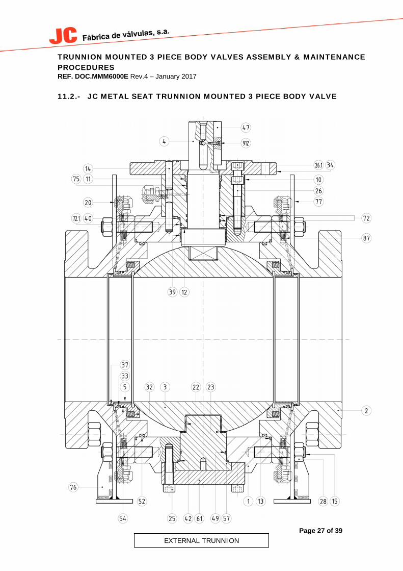
11.2.- JC METAL SEAT TRUNNION MOUNTED 3 PIECE BODY VALVE
EXTERNAL TRUNNION

TRUNNION MOUNTED 3 PIECE BODY VALVES ASSEMBLY & MAINTENANCE PROCEDURES REF. DOC.MMM6000E Rev.4 – January 2017
Page 28 of 39
INTERNAL TRUNNION
TRUNNION MOUNTED 3 PIECE BODY VALVES ASSEMBLY & MAINTENANCE PROCEDURES REF. DOC.MMM6000E Rev.4 – January 2017
Page 29 of 39
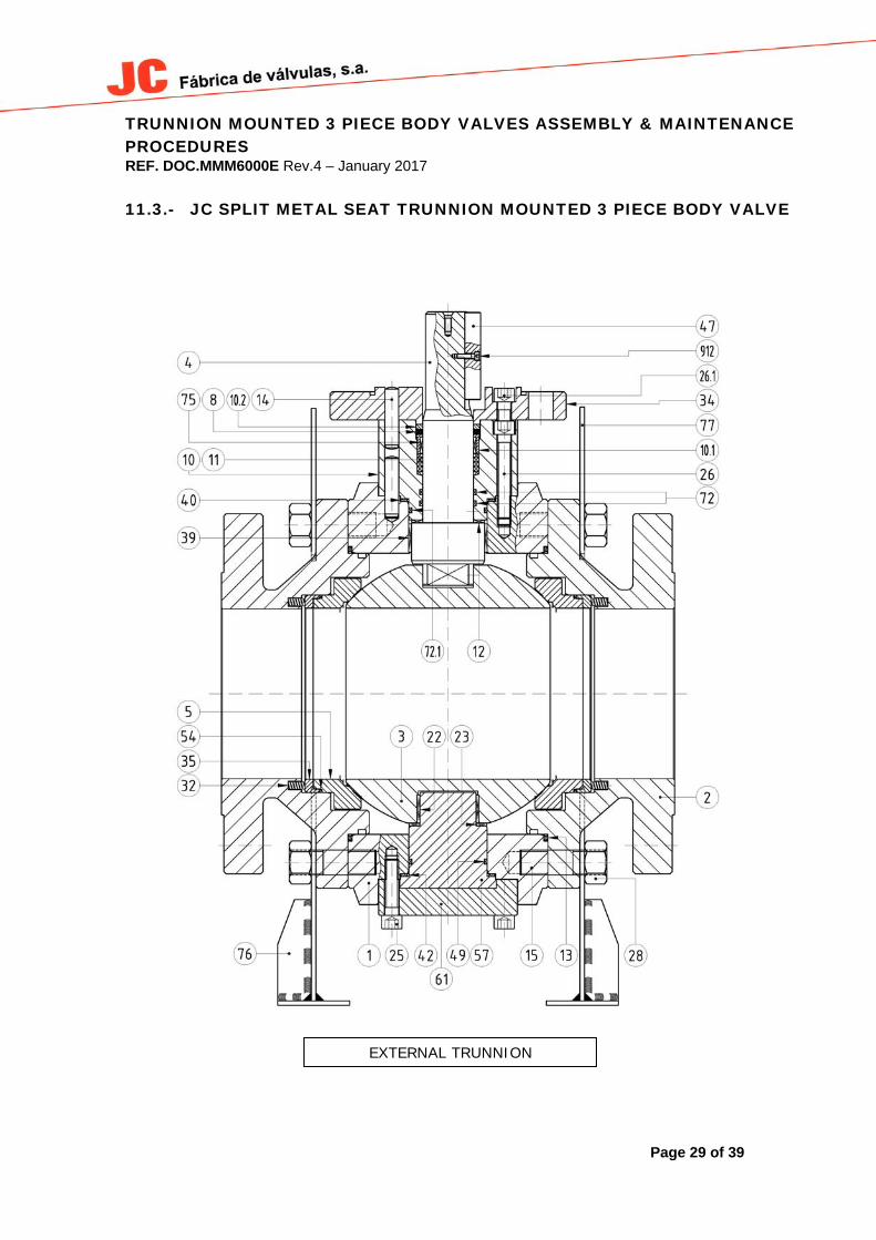
11.3.- JC SPLIT METAL SEAT TRUNNION MOUNTED 3 PIECE BODY VALVE
EXTERNAL TRUNNION

TRUNNION MOUNTED 3 PIECE BODY VALVES ASSEMBLY & MAINTENANCE PROCEDURES REF. DOC.MMM6000E Rev.4 – January 2017
Page 30 of 39
INTERNAL TRUNNION

TRUNNION MOUNTED 3 PIECE BODY VALVES ASSEMBLY & MAINTENANCE PROCEDURES REF. DOC.MMM6000E Rev.4 – January 2017
Page 31 of 39
12.- SAFETY AND USE
According to IEC 61508-2 Annex D 1.0 Introduction
1.1 Scope This manual provides necessary requirements for meeting the IEC 61508 or IEC 61511 functional safety standards and information necessary to design, install, verify and maintain a Safety Instrumented Function (SIF) using JC valves.
1.2 Terms and Abbreviations Describe Basic Terms of Functional safety: What is functional safety, safety function, safe state, fail safe, Fail safe, fail dangerous, low demand mode etc. Typical abbreviations: - FMEDA: Failure Modes, Effects and Diagnostic Analysis - HFT: Hardware Fault Tolerance - PFDAVG: Average Probability of Failure on Demand - SFF: Safe Failure Fraction, the fraction of the overall failure rate of a device that results in either
a safe fault or a diagnosed unsafe fault. - SIF: Safety Instrumented Function, a set of equipment intended to reduce the risk due to a
specific hazard (a safety loop), Safety instrumented control/protection function - SIL: Safety Integrity Level, discrete level (one out of a possible four) for specifying the safety
integrity requirements of the safety functions to be allocated to the E/E/PE safety-related systems where Safety Integrity Level 4 has the highest level of safety integrity and Safety Integrity Level 1 has the lowest.
- SIS: Safety Instrumented System — Implementation system of one or more Safety Instrumented Functions. A SIS is composed of any combination of sensor(s), logic solver(s), and final element(s).
- DC: Diagnostic Coverage Factor (if diagnostic measures exist) - PTC: Proof Test Coverage Factor - PFH: Probability of dangerous failure per hour - PFD: Probability of dangerous failure per demand
1.3 Reference Documents
- JC Valves Product Data Sheet - Notify body report and Certificate - JC Valves Maintenance and installation instructions (This document). - Special operating Instructions :
Valves manufactured by JC Valves can be equipped with a variety of: Operating mechanisms, such as handwheel, gear, electric actuator, hydraulic actuator or pneumatic actuator. Motorized valves are supplied with the actuators installed and torque and position limits correctly adjusted. For opening the valve, handwheel must be rotated counter-clockwise. Open and close position will be done by the stop regulation devices.
TRUNNION MOUNTED 3 PIECE BODY VALVES ASSEMBLY & MAINTENANCE PROCEDURES REF. DOC.MMM6000E Rev.4 – January 2017
Page 32 of 39
Unless otherwise specified, gearing in most cases is sized to close with a maximum 35Kg rim pull on the gearing handwheel at a differential shut-off pressure equal to the class of the valve. If the actual differential pressure is known, or a different rim pull is required, this information should be specified as the gearing size may change. The information required to custom size gearing is as follows: a) Operating conditions b) Differential shut-off pressure c) Maximum allowable hand wheel rim pull d) Desired hand wheel orientation. The high speed of operations in modern industry and the necessity of making process plant operations automatic have increased the need for motor operated valves. Such applications include those where the valve: 1. Is too large or has too high a differential shut-off pressure for manual operation. 2. Is not accessible for manual operation, 3. Is part of a system requiring simultaneous operation of many valves, 4. Must be triggered form a remote location, as is often essential for emergency shut-off in hazardous areas. Actuator manufacturer’s instructions must be followed in case the valve is equipped with an actuator (electric, pneumatic or hydraulic). Torque, limit switches and additional parameters are adjusted in factory before shipment. Contact JC Valves before changing any parameters. Any actuator mounted on a JC Valve has a position indicator for indicating if the valve is open or closed. This position indicator depends on the actuator type; it can be a digital or a mechanical indicator. Generally motor operating units, as illustrated are top-mounted. Side mounted units can be supplied where deemed necessary by valves manufacturer and actuators supplier. All valves are furnished with special purpose yokes designed for the motor operating unit to be used, following ISO 5211. Electric driven motor actuators consist of a special motor, a reduction gear, and necessary control components, all contained in a weather resisting enclosure, suitable for outdoor installation. Moreover units can be supplied with all necessary contacts for local or remote indication. For hazardous locations, electric control units can also be furnished, on request, with flameproof or explosion proof enclosures, depending on specifications followed by the customer.
1.4 Related Standards - IEC 61508 Parts 1-2 and 4-7:2010 Functional safety of electrical/electronic/ programmable
electronic safety-related systems - IEC 61511 Parts 1-3:2004

TRUNNION MOUNTED 3 PIECE BODY VALVES ASSEMBLY & MAINTENANCE PROCEDURES REF. DOC.MMM6000E Rev.4 – January 2017
Page 33 of 39
2.0 Product Description
The ball valve is the ideal valve for perfect sealing requirements; shutoff applications such as tie-ins, maintenance isolations, line closure, etc. JC VALVES is the reference in ball valves due to our experience, quality and customer satisfaction ratio. Around 25,000 tests have been carried out at our testing facilities and in total, more than 250.000 ball valves have been manufactured. Due to the extremely long durability of our ball valves, the end user benefits not only with quality but also with lower maintenance costs. We have a solid working knowledge about the design of ball valves and the materials needed in their construction. This has led to JC VALVES becoming not only an expert in ball valves but also a leader in this market. Significant characteristics: JC VALVES manufactures metal seated ball valves for high temperature applications and severe service applications. Special coatings can be applied for any internal part in contact with fluids, depending on the customer’s needs. JC VALVES also has an extensive and proven experience in valves for cryogenic service.
3.0 Functional Safety relevant specifications
3.1 Safety Function The JC Valves are typically used in ON/OFF services, so the safety function of a valve is to stop or allow the fluid pass through it. In an emergency situation the valve must be able to close without leakage as fast as the equipment that operate the valve can do it.
3.2 Environmental Limits - Temperatures - External pressure greater than atmospheric pressure - Wind, snow and ice - Acoustic vibration and/or vibration caused by the fluid - Shock waves - Flame - Lightening - Electromagnetic waves from 3x10^11HZ to 3x10^12 Hz. - Radio frequency (RF) electromagnetic waves from 10^4 to 3x10^12; - Environmental variations
3.3 Application Limits JC VALVES is the perfect partner for the customers who require valves for special applications such as: extremely low or extremely high temperatures, high pressure, highly corrosive applications, suspension solids with unusual temperature ranges, maximum weight capacities, unexpected issues during the process, acidic products and critical plant safety applications. We have long experience supplying valves for different projects with require special valves for offshore platforms, PTA plants, as well as plants and services with extremely corrosive environments. Our Technological Services will attend to any special requirements.

TRUNNION MOUNTED 3 PIECE BODY VALVES ASSEMBLY & MAINTENANCE PROCEDURES REF. DOC.MMM6000E Rev.4 – January 2017
Page 34 of 39
Our focus in innovation has made it possible to manufacture new high specification products for special applications such as:
Tandem gate valves for Hydrogen service. Metal seated HIPPS ball valves. Double metal seated ball valves. From cryogenic temperature to high temperature range Ball valves. Flow regulation Globe manual valves. Special dimension valves. Customized %’s of material content out of standards. Etc.
JC Valves is the most reliable supplier for the most severe requirements and conditions.
The material of constructions of a JC Valves are specified in the JC Valves Datasheets and in the main literature. It is especially important that the designer of the SIF checks for the material compatibility considering on-site chemical contaminants and fluid conditions. If the JC Valves are used outside the application limits or with incompatible materials or environment, the reliability data and predicted SIL capability becomes invalid.
3.4 Design Verification
A detailed Failure Modes, Effects and Diagnostics Analysis (FMEDA) report is available from JC Valves for this product. This report details all failure rates and failure modes as well as expected lifetime of the product. The achieved Safety Integrity Level (SIL) of an entire Safety Instrumented Function (SIF) design must be verified by the designer via calculation of PFDAVG considering the architecture, proof test interval, proof test effectiveness, any automatic diagnostics, average repair time and the specific failures rates of all equipment included in the SIF. Each subsystem must be checked to assure compliance with minimum Hardware Fault Tolerance (HFT) requirements. The failure rate data listed in the FMEDA report is only valid for the useful lifetime of the JC Valve. The failure rates will increase after this useful lifetime period has expired.
3.5 SIL Capability
JC Valves are suitable for use in a safety instrumented system up to SIL 3 A proof test has to be performed once a year in order to accomplish with the safety requirements.
3.6 General Requirements
The JC Valve will be moved to its defined safe state (closed) in relation to the specific hazard scenario. All SIS components must be operational before process start-up. The User shall verify that the JC Valve is suitable for use in safety applications by confirming the JC Valve nameplate and model number is properly marked. Personnel performing maintenance and testing on the JC Valve shall first be assessed as being competent to do so. Result from periodic proof tests shall be recorded and periodically reviewed. The JC Valve shall not be operated beyond the useful lifetime.
TRUNNION MOUNTED 3 PIECE BODY VALVES ASSEMBLY & MAINTENANCE PROCEDURES REF. DOC.MMM6000E Rev.4 – January 2017
Page 35 of 39
4.0 Installation and commissioning
4.1.- SAFETY INSTALLATION AND STORAGE - The handling of valves, both whilst they are still inside the packaging and when they have been removed from it, is to be undertaken in accordance with the Assembly & Maintenance Manual. - Check the packaging is fully secure in the event that it is to be moved. - Always use endorsed chains and mooring straps of sufficient strength for moving the valve or the crates. Make sure they are in good condition. The weight of the crates is specified on them, and the weight of the valves is indicated on the corresponding drawings. - Hold the boxes by the marked mooring points. - Never pass a valve or a crate through the air over a person. - Storing valves must be carried out according the Assembly & Maintenance Manual. - When opening the crates, be careful with packing nails. Never leave the point of a nail sticking out, remove the nail completely from the crate if necessary. Do not handle crates with bare hands are there could be splinters. - When the valve is installed at a height above the ground, follow local safety regulations on working at heights. - When the valve is welded on to the line, use suitable protection and safety equipment.

TRUNNION MOUNTED 3 PIECE BODY VALVES ASSEMBLY & MAINTENANCE PROCEDURES REF. DOC.MMM6000E Rev.4 – January 2017
Page 36 of 39
APPENDIX 1: PS05 I26 ASSEMBLY DINAMOMETRIC WRENCH TABLE
5.6 MATERIAL
THREAD TORQUE (Nm) WRENCH
DINAMOMETRIC
326 (10-100) 96 (20-100) 324 (20-200) 325 (75-400)M6 6 10 M8 14 14 M10 28 17 M12 49 19 M14 77 22 M16 121 24
M20 235 30
MATERIAL 8.8 (640)
THREAD TORQUE (Nm) WRENCH
DINAMOMETRIC
326 (10-100) 96 (20-100) 324 (20-200) 325 (75-400)M6 12 10 M8 30 14
M10 59 17 M12 104 19 M14 165 22 M16 257 24
M20 502 30
A4-70 MATERIAL
THREAD TORQUE (Nm) WRENCH
DINAMOMETRIC
326 (10-100) 96 (20-100) 324 (20-200) 325 (75-400)M6 9 10 M8 21 14
M10 42 17 M12 73 19 M14 116 22 M16 181 24
M20 353 30

TRUNNION MOUNTED 3 PIECE BODY VALVES ASSEMBLY & MAINTENANCE PROCEDURES REF. DOC.MMM6000E Rev.4 – January 2017
Page 37 of 39
B7M / L7M MATERIAL
THREAD TORQUE (Nm) WRENCH
DINAMOMETRIC
326 (10-100) 96 (20-100) 324 (20-200) 325 (75-400)3/8" 40 17
7/16" 55 18
1/2" 70 22 9/16" 110 22 5/8" 165 24 3/4" 270 28/32 7/8" 430 36 1" 720 41
1-1/8" 930 42
1-1/4” 1280 --
1-3/8” 1670 --
1-1/2” 2470 --
B8 / B8M MATERIAL
THREAD TORQUE (Nm) WRENCH
DINAMOMETRIC
326 (10-100) 96 (20-100) 324 (20-200) 325 (75-400)3/8" 16 17
7/16" 20 18
1/2" 26 22 9/16" 42 22 5/8" 63 24 3/4" 100 32 7/8" 168 36 1" 250 41
1-1/8" 350 42
1-1/4” 480 --
1-3/8” 700 --
1-1/2” 950 --

TRUNNION MOUNTED 3 PIECE BODY VALVES ASSEMBLY & MAINTENANCE PROCEDURES REF. DOC.MMM6000E Rev.4 – January 2017
Page 38 of 39
L7 / B7 MATERIAL
THREAD TORQUE (Nm) WRENCH
DINAMOMETRIC
326 (10-100) 96 (20-100) 324 (20-200) 325 (75-400)3/8" 48 17
7/16" 78 18 1/2" 118 22
9/16" 167 22
5/8" 231 24
3/4" 400 28/32
7/8" 651 36
1" 970 41
1-1/8" 1421 42
1-1/4” 2300 -- 1-3/8” 3020 --
1-1/2” 4010 --
MATERIAL L7 / B7 (720)
THREAD TORQUE (Nm) WRENCH
DINAMOMETRIC 326 (10-
100) 96 (20-
100) 324 (20-200) 325 (75-400) M6 11 10 M8 28 14 M10 55 17
M12 94 19
M14 150 22 M16 235 24
M20 457 30
To convert Nm to mKg you must divide by 10. For A4-80 materials use the same values as A4-70

TRUNNION MOUNTED 3 PIECE BODY VALVES ASSEMBLY & MAINTENANCE PROCEDURES REF. DOC.MMM6000E Rev.4 – January 2017
Page 39 of 39
VEREENIGINGTel: 011 397 2833Fax: 011 397 4700
DURBANTel: 031 579 2593Fax: 031 579 2562
E-mail: [email protected]: [email protected]