anthony gardiner taglifting 201212taglifting.com.au/manuals/oro/lift_drive_manual.pdf · as regards...
TRANSCRIPT

º
Document code: 0466017
Version: 4
Last revision: 21/07/2009
Unidrive SP – Lift Speed Control System
#ANTHONY_GARDINER_TAGLIFTING_201212#
ANTHONY_GARDINER_TAGLIFTING_201212

INDEX
0466017 - Unidrive SP – Lift Speed Control System 2/83
INDEX INDEX ................................................................................................................................................ 2 1. INTRODUCTION ....................................................................................................................... 3 1.1. DRIVE OPERATION ............................................................................................................... 3 1.2. MODELS AND SIZES ............................................................................................................. 3 1.3. OVERVIEW .......................................................................................................................... 4 1.4. ADDITIONAL CARDS ............................................................................................................. 6 1.5. INTERNAL PROGRAMMING ..................................................................................................... 6
2. CONNECTIONS ........................................................................................................................ 8 2.1. POWER CONNECTIONS.......................................................................................................... 8 2.2. ENCODER CONNECTION ........................................................................................................ 8 2.3. CONTROL CONNECTIONS ...................................................................................................... 8
3. USER INTERFACE ................................................................................................................... 10 3.1. KEYPAD PLUS ..................................................................................................................... 10 3.2. CONNECTION TO ORONA CONTROLLER ................................................................................. 12 3.3. SMARTCARD ...................................................................................................................... 13
4. ADVANCE PARAMETER ADJUSTMENT ........................................................................................ 14 4.1. INTERNAL OPERATION ........................................................................................................ 14 4.2. MOTOR CONFIGURATION .................................................................................................... 14 4.3. ENCODER CONFIGURATION ................................................................................................. 20 4.4. OPERATING SEQUENCE ....................................................................................................... 20 4.5. SPEED PROFILES ................................................................................................................ 23 4.6. INERTIA COMPENSATION .................................................................................................... 26 4.7. SPEED CONTROL ................................................................................................................ 26 4.8. CURRENT CONTROL (TORQUE) ............................................................................................. 26 4.9. START COMPENSATION ....................................................................................................... 27 4.10. BRAKING RESISTANCE ........................................................................................................ 29 4.11. RESCUE OPERATION ........................................................................................................... 29 4.12. RFC MODE ......................................................................................................................... 29
5. FUNCTIONS ........................................................................................................................... 30 5.1. INVERSION OF DIRECTION OF ROTATION ............................................................................. 30 5.2. MOTOR AUTO TUNING ........................................................................................................ 31 5.3. SM-APPS.LITE SPECIAL FUNCTIONS ..................................................................................... 32
6. PROBLEM SOLVING ................................................................................................................ 37 6.1. PROGRAMMING PROBLEMS .................................................................................................. 37 6.2. DISPLAYING STATUS VARIABLES ......................................................................................... 40 6.3. PERMANENT MAGNET SYNCHRONOUS MOTORS ..................................................................... 41 6.4. FREQUENT PROBLEMS ......................................................................................................... 42 6.5. DRIVE FAULTS ................................................................................................................... 51 6.6. CABLING ADVICE ............................................................................................................... 56
7. INDEX OF ELECTRICAL DIAGRAMS ........................................................................................... 60 8. REPLACEMENT PARTS ............................................................................................................. 61 8.1. EQUIPMENT REPLACEMENT .................................................................................................. 61 8.2. ADDING AN SM-APPS.LITE CARD .......................................................................................... 61 8.3. REPLACEMENT CODES......................................................................................................... 62
9. DEFAULT PARAMETERS ........................................................................................................... 66 9.1. INSTALLATION TYPES ......................................................................................................... 66 9.2. PARAMETER LISTS FOR EACH INSTALLATION ........................................................................ 67
#ANTHONY_GARDINER_TAGLIFTING_201212#
ANTHONY_GARDINER_TAGLIFTING_201212

INTRODUCTION
0466017 - Unidrive SP – Lift Speed Control System 3/83
1. INTRODUCTION
The Unidrive SP controller is a frequency drive made by “Control Techniques” that provides control for asynchronous and synchronous motors.
As regards Orona, this drive can be used to control the following types of vertical lift motor:
• Geared Asynchronous motors (O-140, O-170, SASSI) with closed loop control (with encoder).
• Gearless synchronous motors: M33, M33 optimised, M34, Nuevo Renova Electrico, Zetatop (Ziehl-Abegg) and Z6 or Z10 (Leroy Somer).
1.1. DRIVE OPERATION
The drive is based on an Insulated Gate Bipolar transistor (IGBT) based frequency converter that works in Pulse Width Modulation (P.W.M.) with an elevated switching frequency (3-16kHz, 8kHz by default), ensuring silent operation. This system allows motor supply voltage and frequency to be controlled, providing precise control over speed and torque for any motor operating state.
At the supply input, the Unidrive SP has a diode bridge to convert three-phase alternating current into direct current, which is what is required to supply the transistors. This “DC bus” contains capacitors to prevent the voltage oscillating.
DANGER: Accumulated Load in Capacitors The voltage accumulated by the capacitors is potentially mortal. After disconnecting the power supply, wait 10 minutes before connecting/disconnecting power cables (power supply, motor, DC bus or braking resistor).
When the lift moves in the load direction, the energy returned by the motor has to be dissipated by a brake resistance so as not to damage the DC bus capacitors. Where this resistance fails or is not connected, the drive is automatically disconnected before the capacitors can be destroyed.
To guarantee electromagnetic compatibility (EMC), the drive requires an anti-interference filter at the power supply input and the use of shielded and ferrite cables at the motor output (as described in section 6.6).
The control unit is based on a digital microprocessor system, that uses information about motor speed (read from the encoder) and power consumption (internal drive reading) to control motor speed and torque at all times engine to achieve an optimum speed profile under any load condition.
1.2. MODELS AND SIZES
Drive size and specific model can be identified from the label on the front panel (see point 1.3):
Within the drive model, the first number indicates its physical size (at Orona sizes 1 to 4 are used). Within each size, there are various alternatives depending on motor voltage that can be controlled:
Model and size Control Techniques serial number
#ANTHONY_GARDINER_TAGLIFTING_201212#
ANTHONY_GARDINER_TAGLIFTING_201212

INTRODUCTION
0466017 - Unidrive SP – Lift Speed Control System 4/83
Model Size Drive Power
Rated Current (acc.
manufacturer)
Rated Current (Orona application
table)
1405
3kW 7.6 A 7.5 A
1406 4 kW 9.5 A 9.5 A
2401
5.5 kW 13 A 12 A
2402 7.5 kW 16.5 A 15.6 A
2403 11 kW 25 A 23.6 A
2404 13.5 kW 29 A 26.6 A
3401
15 kW 32 A 30.3 A
3402 18.5 kW 40 A 37.8 A
3403 22 kW 46 A 43.5 A
4401
30 kW 60 A 56.8 A
4402 37 kW 74 A 68 A
4403 45 kW 96 A 85 A
Brake resistance models depend on lift type and power, consult section 8.3.
1.3. OVERVIEW
All sizes:
Serial connection
SmartCard
slot
Status LED
Label
Additional card slots
Off: controller powered off
On: controller operational
Blinking: controller faulty
Control signal connectors
Alarm signal connector
Encoder connector
Slot 3
Slot 2
Slot 1
#ANTHONY_GARDINER_TAGLIFTING_201212#
ANTHONY_GARDINER_TAGLIFTING_201212

INTRODUCTION
0466017 - Unidrive SP – Lift Speed Control System 5/83
Sizes 1, 2 and 3:
Size 4:
Supply (L1,L2,L3)
Motor output (U,V,W)
Brake resistance (+DC – BR)
Brake resistance (DC2/+DC – BR)
Supply (L1,L2,L3) y motor output (U,V,W)
*
* * *
(*) Internal filter:
Removed at factory because not compatible with external filter
#ANTHONY_GARDINER_TAGLIFTING_201212#
ANTHONY_GARDINER_TAGLIFTING_201212

INTRODUCTION
0466017 - Unidrive SP – Lift Speed Control System 6/83
1.4. ADDITIONAL CARDS
The Unidrive SP can carry diverse optional cards to provide additional features. These cards are placed in the slots under the front cover, and up to 3 cards can be inserted per drive.
There are a great variety of cards that allow, for example, inputs and outputs to be added to the drive, special encoders to be controlled, etc. Each of these cards can be identified by its colour.
When the drive starts up and detects that a card has been removed or added, it gives an (SL.rtd) fault that can be reset from the Keypad Plus or from the Drive menu on the Maintenance Terminal (TMR).
ATTENTION To install or remove a card, disconnect the power from the drive and wait at least one minute.
1.4.1. SM-Apps.Lite card
The card most used by Orona is the ‘SM-Apps.Lite’, which can be identified by its white colour. This card contains a microprocessor and memory independent from those inside the drive.
The program it contains (factory installed) allows additional features to be added as described in later
sections. Must be inserted in lowest slot (slot 3).
This card is being installed in all drives from April 2009, although it can also be installed in older drives.
1.4.2. SM-I/O Plus card
This card allows additional inputs and outputs to be added to the drive. It is only used in ARCA I lifts where an original M33 machine has been replaced with an optimised M33 machine. Provides the drive with a brake contact reader (as the ARCA I controller doesn’t have one). Does not contain a program, menu 17 which corresponds to slot 3 is simply programmed, which is where the card should be inserted. Installation of this card is described in instruction IIM-036-0 (M33 Machine kit and throw frame).
1.5. INTERNAL PROGRAMMING
1.5.1. Basic parameters
All Unidrive SP drives are configured using a series of parameters distributed on menus. These parameters have a type 12.40 denomination, which means parameter 40 of menu 12. These parameters can be bits (on/off), whole numbers or numbers with decimals. Some of these are “read only” and serve to display the state of certain internal signals. In these instructions, references to drive parameters will be preceded with ‘Pr’ (for example, Pr 0.14). Section 3 describes how to access these parameters.
Parameter values can be recorded and recovered to/from the SmartCard or a PC (via CTSoft software). Programming of these parameters is different depending on the type of installation, the load and the speed.
#ANTHONY_GARDINER_TAGLIFTING_201212#
ANTHONY_GARDINER_TAGLIFTING_201212

INTRODUCTION
0466017 - Unidrive SP – Lift Speed Control System 7/83
1.5.2. PLC Software:
In addition to these parameters, the drive contains a small internal automaton called a PLC to better adapt the product to the application (in Orona's case, the lift). This PLC software is recorded on all Unidrive SP drives except the "original" M33.
The PLC can be recorded and recovered to/from the SmartCard or a PC using SYPTLite software. There are 2 different software programmes, one for asynchronous motors and the other for synchronous motors.
1.5.3. DPL Software
The SM-Apps.Lite card, like the PLC, enables native code to be developed, called DPL, to adapt the drive to the lift, but its memory and processing capacity is very much superior.
The DPL software recorded on the card performs the same functions as the PLC and provides additional features (described further on). Drives with the factory installed SM-Apps.Lite card, will have a programmed but deactivated PLC and the operating sequence will be handled by the software on the SM-Apps.Lite card.
The software on the card does not change with the appliance type, although in time new versions of the software will appear (this can be queried via parameter Pr 20.17). In the event of a card fault, it can be stopped and the PLC activated whist it is replaced, as described in section 6.1.5.
The DPL software on the SM-Apps.Lite card cannot be recorded or recovered from the SmartCard. A PC and Winflasher software are necessary for recording.
Lift type Basic
parameters PLC
Software DPL Software
M322 YES Asynchronous
Only if SM-Apps.Lite
card inserted
Machine room YES Asynchronous
M33 original YES NO
M33 extended YES Synchronous
M33 optimized YES Synchronous
MRL Ziehl-Abegg / Leroy-Somer YES Synchronous
M34 YES Synchronous
ATTENTION: IF THE DRIVE HAS AN Apps.Lite CARD The PLC and DPL programs are recorded on the drive, but they can no operate simultaneously. The SM-Apps.Lite card (DPL) program deactivates the PLC automatically on start up.
Parameters exist for displaying the status of the PLC and DPL software, which can be accessed via the Orona MT or the Keypad Plus:
Software and status Keypad Plus Orona MT
PLC Software Pr 11.48 5.7.3 Status
Not recorded 0 No
Stopped 1 Stop
Running 2 Run
DPL Software Pr 17.03 5.7.3 Status
Not recorded nonE (0) No
Manually stopped StoP (1) Stop
Running Run (2) Run
Stopped due to an error triP (3) Av
SM-Apps.Lite card not installed Menu 17 doesn’t exist No
#ANTHONY_GARDINER_TAGLIFTING_201212#
ANTHONY_GARDINER_TAGLIFTING_201212

CONNECTIONS
0466017 - Unidrive SP – Lift Speed Control System 8/83
2. CONNECTIONS
Frequency drive IGBT switching causes electromagnetic interference. To minimize its effect it is essential that the electrical connections are made as indicated in this section and in section 6.6.
The location of all terminals described is displayed in section 1.3.
2.1. POWER CONNECTIONS
DANGER: Accumulated Load in Capacitors The voltage accumulated by the capacitors is potentially mortal. After disconnecting the power supply, wait at least 10 minutes before connecting/disconnecting power cables (power supply, motor, DC bus or braking resistor).
The drive must be supplied from a 380-415V three-phase supply via terminals L1, L2, L3. To ensure compliance with lift regulations an electromagnetic compatibility filter, a circuit breaker and a residual current device must be employed.
The braking resistor must be connected between terminal BR and terminal DC2 or DC+ (the name changes depending on drive size) and the cable-set that joins the drive with the resistor must be shielded, and the mesh must be fastened to the plating via metallic straps at each end.
The power output (terminals U,V,W) goes to power contactor C1. This stretch of cable, to minimise electromagnetic emissions, is short and is would 2 or 3 times around some ferrite. The cable from the contactors to the motor is connected using shielded cabling for the same reason, and the mesh must be fastened to the case via metallic straps at each end.
2.2. ENCODER CONNECTION
The Unidrive SP uses an encoder reading to control motor rotation speed. A good signal is fundamental for guaranteeing proper system operation.
To ensure this shielded cable is used which is connected to the front of the drive via a “Sub D-15” connector.
PRECAUTION The encoder cable should be protected by separating it as much as possible from the motor power cables and it is recommended that it be replaced if damaged or cut.
2.3. CONTROL CONNECTIONS
The controller controls drive operation (and thereby that of the motor) via a set of control signals:
• Secure Disable: this signal indicates to the drive that it should apply current to the motor output because the contactors have operated.
• Rescue: indicates that the emergency EMC contactor has operated and that the drive should operate in rescue mode (see section 4.11).
• Speed levels B1, B2, B3: these 3 digital signals set movement speed via a binary code (see section 4.5.1).
• Ascend/Descend: these 2 digital signals set the movement direction.
ATTENTION For the ‘up’ signal to work there must be a bridge between terminals 3 and 6.
#ANTHONY_GARDINER_TAGLIFTING_201212#
ANTHONY_GARDINER_TAGLIFTING_201212

CONNECTIONS
0466017 - Unidrive SP – Lift Speed Control System 9/83
The cabling for these inputs is shown in the table:
Signal Terminal
Connection
Common (24V internal) 22
Secure Disable 31
Ascend 5
Descend 8
B1 Speed level 29
B2 Speed level 28
B3 Speed level 27
Rescue 26
(*) These 1kΩ resistances go to the internal drive 0V (terminals 11 and 23) and make inputs more robust as regards electromagnetic interference.
In the case M33, M33 extended, M33 optimized, Leroy-Somer or Ziehl-Abegg lifts, a car load level reading is also used to open the car brake as soon as it moves and achieve optimum comfort:
Signal Terminal Type
Weight level (+) 7 A 0-10V (PQ Orona) or 0-20mA (Micelect LM3D) signal can be
used. See section 0 Weight reference (-) 3
In addition, the drive has the following outputs to the controller:
Signal Terminal Use
Drive alarm (relay contact)
41 - 42 Relay contact that opens if the drive is faulty, indicating to the controller that it should not attempt to move.
Brake opening (24V transistor)
24 (+) y 11 (-) Allows the drive to control brake opening to improve comfort (see section 4.4).
Advance door opening (24V transistor)
25 (+) y 11 (-) Only ARCAI lifts. Activates if car speed is less than 0.3m/s (allowing doors to open).
To see the status of these inputs and outputs, see section 6.2.1.
31
27 28 29
22
26
C1 C2
EMC
5 8
PBCM 23
11 K5 K6 K7
K3 K4
*
*
3 6
Unidrive SP
#ANTHONY_GARDINER_TAGLIFTING_201212#
ANTHONY_GARDINER_TAGLIFTING_201212

USER INTERFACE
0466017 - Unidrive SP – Lift Speed Control System 10/83
3. USER INTERFACE
3.1. KEYPAD PLUS
The Keypad Plus is a Control Techniques tool that allows internal drive parameters to be displayed and modified, faults to be resolved, etc. It connects to the serial port on the drive front panel via a standard straight RJ45 cable:
The Keypad contains several pushbuttons, the most important being: Mode: to change between different modes: status, parameter display and parameter editing
Reset: enables the equipment to recover from faults and also serves to execute certain special functions (see further on).
Help: a brief description of the parameter selected appears on screen when pressed.
Arrows: for navigating parameters and menus, and changing parameter values. This is described in the section on Using the Keypad Plus.
The keypad display consists of 3 alphanumeric horizontal lines:
• The top line displays: • The parameter selected or the drive status in the left corner.
• The parameter value or the current fault in the event that the drive is faulty, in the right corner.
• The 2 bottom lines display a description of the parameter (or the help text if the Help key has been pressed).
Status indication
When first connected to a drive, wait at least one minute for it to update itself (will indicate Reading Data Base and Programming Flash).
The keypad is in Status Mode by default, that is, it displays drive status:
• inh: the drive is not faulty but does not apply power (because the controller has not indicated that it should do so via the SecureDisable input).
• run: the drive is applying power to move the motor.
• StoP: the drive applies power to keep the motor stopped. Appears when Direction, Speed and SecureDisable set points are removed next to Dec (decelerating).
• PLC: PLC software is running (see section 1.5.2). This indication blinks every 10 seconds or so.
#ANTHONY_GARDINER_TAGLIFTING_201212#
ANTHONY_GARDINER_TAGLIFTING_201212

USER INTERFACE
0466017 - Unidrive SP – Lift Speed Control System 11/83
• triP: the drive detects a fault and will not apply power to the motor until it has been resolved. The screen also displays a fault code (see section 6.5).
• Auto / TunE: blinks during auto tuning (see section 5.2). • rdY: when a SecureDisable signal is present, but no operating signals (direction or speed). The
drive does not provide output. This should not arise in Orona applications, but if it were to appear, cabling should be checked and the error location established.
• no link: when the keypad Plus is remotely connected (with network cable) and an operation is being performed (record to/from Smartcard, etc...). Despite the appearance of this message, the operation is executed correctly.
Using the Keypad Plus:
Status Mode
The top left hand side indicates drive status (doesn’t blink).
The top right hand side indicates the fault code (only where present, in which case it blinks).
Parameter Mode
The top left hand side indicates parameter selected (blinks).
The top right hand side indicates the value for this parameter.
This mode serves for navigating the different drive menus and viewing its parameter values.
After a while in this mode without pressing a button, the keypad automatically returns to Status Mode.
Editing Mode
The top left hand side indicates parameter selected.
The top right hand side indicates the value for this parameter. The digit to be modified blinks.
This mode serves to modify parameter values.
After a while in this mode without pressing a button, the keypad automatically returns to Status Mode.
(*) Some drive parameters are “Read Only”, and therefore access to Editing Mode may not be possible.
0.15 65
0.15 65
To access Parameter Mode, Press
or
Use the vertical arrows to change parameter
To access Edit mode, press
*
0.15 45
Use the horizontal arrows to select the digit you wish to
change
0.15 45
0.15 45
Use the vertical keys to change the digit value
To return to Parameter Mode, validating the new parameter
value, press
inh 0
To return to Status Mode, press
again
0.10 0
#ANTHONY_GARDINER_TAGLIFTING_201212#
ANTHONY_GARDINER_TAGLIFTING_201212

USER INTERFACE
0466017 - Unidrive SP – Lift Speed Control System 12/83
Advanced Menu Access
By default, only menu 0 parameters (Pr 0.XX) can be accessed from the Keypad Plus. If Pr 0.49 is changed from L1 to L2, the rest of the menus can be accessed when pressing left and right keys (parameters for menu 1 are Pr 1.XX, menu 2 are Pr 2.XX…).
Fault recovery
If the drive has a fault, the screen will display triP and a fault code. Section 6.5 provides
descriptions for all the faults that can be cause them. To recover, press the reset button .
Parameter recording
If a parameter has been modified, by pressing the M button it is only stored in volatile memory, and it will therefore be lost following a power down. To permanently record parameters, enter
value 1000 for Pr x.00 (in any menu) and press the reset button .
3.2. CONNECTION TO ORONA CONTROLLER
The drive can be customized and monitored via the Orona Maintenance Terminal. To do so the Arca II controller communicates via 485 through the serial port on the front of the drive (such as on the Keypad Plus).
This communication is not possible with original and extended M33 lifts. For the rest this can be performed in two ways:
• Directly from the main board. Only 5124423 main boards (June 2009) are prepared for this.
• Via a loadweights board (5124340), which acts as a “translator” from CAN bus to RS485. This communication is used on the Optimized M33, Leroy-Somer and Ziehl-Abegg.
Drive access from the MT
On the Orona MT, the Unidrive SP drive is a controller node. From the Main Menu, enter Current and then Drive. If there are no Unidrive SPs connected (or there is a communications fault) nothing will appear, to the contrary the following menus will be available:
1. FAULTS: can be used to see if the drive is faulty or not, and to recover faults.
2. HISTORIC: this menu allows the last 10 faults registered by the drive to be displayed.
3. VARIABLES: this menu displays the status of some of the drive’s internal variables, speed readings and motor voltage and the status of inputs and outputs.
4. FUNCTIONS: this menu provides access to different drive assembly and maintenance utilities, described in section 5. This menu also includes SmartCard recording and reading functions (see section 3.3).
5. PARAMETERS: any drive parameter can be changed via this menu (as described in section 4). It is important to highlight that the MT (unlike the Keypad Plus) cannot operate with decimals, and therefore many parameters appear in tenths (d), hundredths (c) or thousandths (m). For example, current is in decimals and therefore to program a current of 12A, the parameter should be adjusted to [120]d.
In this standard, references to parameters on these menus takes the form ‘TMR 5.2 Vmax’. IF a parameter only refers to the Keypad Plus (for example, Pr 1.27) the parameter can only be accessed from TMR 5.8 Manual Parameter.
Parameter recording
After modifying parameters (menu 5) or using functions (menu 4), enter TMR 4.3 Store Parameters
= [YE] to not loose changes when the power is turned off.
#ANTHONY_GARDINER_TAGLIFTING_201212#
ANTHONY_GARDINER_TAGLIFTING_201212

USER INTERFACE
0466017 - Unidrive SP – Lift Speed Control System 13/83
3.3. SMARTCARD
All drives come with a SmartCard. At the factory all drive parameters and PLC software for each installation are recorded on the card, which can therefore be used to restore original parameters in the event of undesired modifications, or drive substitution by a new unit.
The card should be inserted with the contacts facing the right side of the drive. There is no need to turn off the power when inserting or removing the card.
If a fault occurs during any dumping process, observe fault code and consult section 6.5. To recover the fault:
• Using the Keypad Plus: program parameter Pr x.00=0 +
• Using the Orona MT: TMR 1 Fault recov. = YES
Drive programming from the SmartCard When performing this operation drive parameters and PLC program are deleted and are recorded from the contents of the SmartCard:
• Using the Orona MT: a. Recover only parameters: TMR 4.4 Read SM = YES b. Recover parameters and PLC: TMR 4.4 SM -> Inverter = YES
• Using the Keypad Plus: c. Recover PLC program: Pr x.00=6004 + Attention: the 'Original' M33s (i.e. not extended or optimized) did not have a PLC, and therefore this operation should not be performed (would cause an error).
d. Recover parameters: Pr x.00=6001 +
e. Record parameters: Pr x.00=1000 +
Record drive data to SmartCard
When performing this operation factory recorded parameters are lost, but if any encoder or machine modifications have been made (or if an auto adjustment has been performed) it is recommended that the new data be recorded to the card.
• Using the Orona MT: f. Record parameters only: TMR 4.4 Actualise SM = YES g. Record parameters and PLC: TMR 4.4 Inverter -> SM = YES
• Using the Keypad Plus: h. Unprotect SmartCard: Pr x.00=9777 +
i. Delete SmartCard: Pr x.00=9999 +
j. Save PLC software: Pr x.00=5004 + Attention: the 'Original' M33s (i.e. not extended or optimized) did not have a PLC, and therefore this operation should not be performed (would cause an error).
k. Record parameters: Pr x.00=3001 +
l. Protect SmartCard: Pr x.00=9888 +
ATTENTION The DPL program on the SM-Apps.Lite card is not recorded on the SmartCard. This card can only be recorded to at the factory or on a PC.
#ANTHONY_GARDINER_TAGLIFTING_201212#
ANTHONY_GARDINER_TAGLIFTING_201212

ADVANCE PARAMETER ADJUSTMENT
0466017 - Unidrive SP – Lift Speed Control System 14/83
4. ADVANCE PARAMETER ADJUSTMENT
4.1. INTERNAL OPERATION
Most drives require the use of PLC or DPL software (see section 1.5).
If the drive has the SM-Apps.Lite card, the DPL software must be running:
• Using the Keypad Plus: Pr 17.03 = run • Using the Orona MT: TMR 5.7.4 Status = run
If the drive does not have the SM-Apps.Lite card and is not an “original M33" (see section 4.2), the PLC software must be running:
• Using the Keypad Plus: Pr 11.48=2 • Using the Orona MT: TMR 5.7.3 Status = run
If the correct software is not running, it can be started as described in section 6.1.
4.2. MOTOR CONFIGURATION
4.2.1. CONTROL MODE
Parameter Pr 0.48 (or TMR 5.1 Mode) determines the type of motor controlled by the drive. The Control Techniques drive can control 2 types of motor:
• Gearless asynchronous motors: Pr 0.48=C.L.VECt (TMR 5.1 Mode = V.L.Closed)
• Gearless synchronous motors: Pr 0.48=SERVO (TMR 5.1 Mode = SERVO)
However, changing the drive control mode (changing Pr 0.48) requires entering a code in Pr 0.00 and resetting all parameters to the default values used by Control Techniques. Given that these values are not valid for the Orona application, do not change the control mode in this manner.
If you wish to change the drive control mode (because it does not correspond to the motor installed), you can:
• Use a SmartCard: the card should be programmed for the correct type of installation. Section 0 describes how the process should be performed.
• Using the SM-Apps.Lite card: if the drive contains this type of card (or if one is installed), the “reset to default parameters” function can be used (see 5.3.3) to program all parameters with the correct values for the installation.
4.2.2. GEARED ASYNCHRONOUS MOTORS
The following motors are asynchronous motors that rotate at high speed (1000-1500rpm) and therefore require gearing to adapt to the lift pulley rotation speed.
To control them, the drive should be configured in Closed Loop Vector mode:
• Using the Keypad Plus: Pr 0.48=C.L.VECt • Using the Orona MT: TMR 5.1 Mode = Closed L.V.
#ANTHONY_GARDINER_TAGLIFTING_201212#
ANTHONY_GARDINER_TAGLIFTING_201212

ADVANCE PARAMETER ADJUSTMENT
0466017 - Unidrive SP – Lift Speed Control System 15/83
M233 MACHINES WITH C.T. FROM JULY 2005
The M322s are geared asynchronous motors and drum brakes. The Control Techniques began to be used in the ARCA II controller (contactors and shaft drive).
Lift type 4-6p
1000rpm 8p
1000rpm 4-6p
1500rpm 8p
1500rpm 10-13p 1500rpm
TMR 5.5.1 Nom current Pr 0.46
107d 10.7
132d 13.2
91d 9.1
125d 12.5
232d 23.2
TMR 5.5.1 Resistance Pr 5.17
1341m 1.341
913m 0.913
1198m 1.198
826m 0.826
371m 0.371
TMR 5.5.1 Inductance Pr 5.24
11690m 11.69
8749m 8.749
9826m 9.826
7611m 7.611
3868m 3.868
TMR 5.5.1 Poles Pr 0.42
3 6
2 4
TMR 5.5.1 Nom. Voltage Pr 0.44
380
TMR 5.5.1 rpm nominal Pr 5.08
946 950 1445 1440 1440
TMR 5.5.1 Pow. factor Pr 0.43
767m 0.767
749m 0.749
775m 0.775
856m 0.856
855m 0.855
TMR 5.5.1 Gain.P.curr Pr 0.38
176 168 148 146 112
TMR 5.5.1 Gain.I.curr Pr 0.39
865 748 773 676 460
O-170 or SASSI MACHINES WITH C.T. FROM JULY 2005
Geared asynchronous machines and drum brakes are used in lifts with machine rooms, which can be Orona (O-170) o SASSI (MF82 or MF94). Only used with Control Techniques with controller ARCA II. If the data is not displayed in the table, program:
• Pr 0.42=4 and Pr 0.44=380 • Pr 0.46 and Pr 5.08 according to rating plate. • Perform a static auto tuning to obtain the rest (see
section 5.2.2).
Lift type O-170 7.5cv
O-170 10cv
O-170 15cv
MF82 16cv
MF82 21cv
MF94 16cv
MF94 22cv
MF94 25cv
MF94 31cv
MF94 34cv
TMR 5.5.1 Nom current Pr 0.46
130d 13
160d 16
230d 23
280d 28
320d 32
28d 28
330d 33
386d 38.6
550d 55
580d 58
TMR 5.5.1 Resistance Pr 5.17
926m 0.926
652m 0.652
444m 0.444
409m 0.409
335m 0.335
415m 0.415
335m 0.335
303m 0.303
135m 0.135
143m 0.143
TMR 5.5.1 Inductance Pr 5.24
8704m 8.704
6411m 6.411
4522m 4.522
3232m 3.232
2742m 2.742
3189m 3.189
2746m 2.746
2504m 2.504
1410m 1.410
1416 1.416
TMR 5.5.1 Poles Pr 0.42
2 4
TMR 5.5.1 Nom. Volt. Pr 0.44
380
TMR 5.5.1 rpm nominal Pr 5.08
1441 1450 1449 1427 1435 1430 1430 1442 1482 1480
TMR 5.5.1 Pow. factor Pr 0.43
820m 0.82
851m 0.851
860m 0.86
793d 0.793
835m 0.835
774m 0.774
847m 0.847
856m 0.856
756m 0.756
723m 0.723
TMR 5.5.1 Gain.P.curr Pr 0.38
131 123 131 120 127 118 128 134 98 122
TMR 5.5.1 Gain.I.curr Pr 0.39
598 534 551 649 665 659 666 692 402 525
#ANTHONY_GARDINER_TAGLIFTING_201212#
ANTHONY_GARDINER_TAGLIFTING_201212
ADVANCE PARAMETER ADJUSTMENT
0466017 - Unidrive SP – Lift Speed Control System 16/83
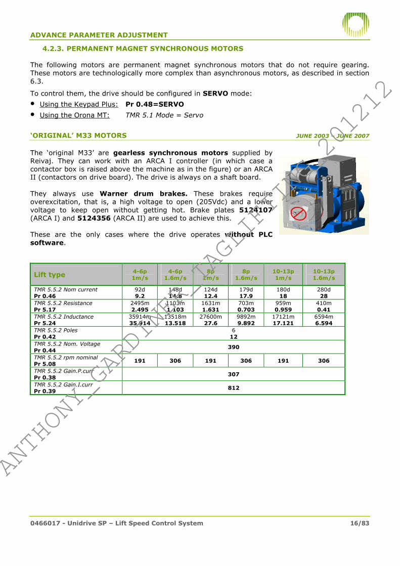
4.2.3. PERMANENT MAGNET SYNCHRONOUS MOTORS
The following motors are permanent magnet synchronous motors that do not require gearing. These motors are technologically more complex than asynchronous motors, as described in section 6.3.
To control them, the drive should be configured in SERVO mode:
• Using the Keypad Plus: Pr 0.48=SERVO • Using the Orona MT: TMR 5.1 Mode = Servo
‘ORIGINAL’ M33 MOTORS JUNE 2003 – JUNE 2007
The ‘original M33’ are gearless synchronous motors supplied by Reivaj. They can work with an ARCA I controller (in which case a contactor box is raised above the machine as in the figure) or an ARCA II (contactors on drive board). The drive is always on a shaft board. They always use Warner drum brakes. These brakes require overexcitation, that is, a high voltage to open (205Vdc) and a lower voltage to keep open without getting hot. Brake plates 5124107 (ARCA I) and 5124356 (ARCA II) are used to achieve this. These are the only cases where the drive operates without PLC software.
Lift type 4-6p 1m/s
4-6p 1.6m/s
8p 1m/s
8p 1.6m/s
10-13p 1m/s
10-13p 1.6m/s
TMR 5.5.2 Nom current Pr 0.46
92d 9.2
148d 14.8
124d 12.4
179d 17.9
180d 18
280d 28
TMR 5.5.2 Resistance Pr 5.17
2495m 2.495
1103m 1.103
1631m 1.631
703m 0.703
959m 0.959
410m 0.41
TMR 5.5.2 Inductance Pr 5.24
35914m 35.914
13518m 13.518
27600m 27.6
9892m 9.892
17121m 17.121
6594m 6.594
TMR 5.5.2 Poles Pr 0.42
6 12
TMR 5.5.2 Nom. Voltage Pr 0.44
390
TMR 5.5.2 rpm nominal Pr 5.08
191 306 191 306 191 306
TMR 5.5.2 Gain.P.curr Pr 0.38
307
TMR 5.5.2 Gain.I.curr Pr 0.39
812
#ANTHONY_GARDINER_TAGLIFTING_201212#
ANTHONY_GARDINER_TAGLIFTING_201212

ADVANCE PARAMETER ADJUSTMENT
0466017 - Unidrive SP – Lift Speed Control System 17/83
EXTENDED M33 MOTORS OCTOBER 2004 – DECEMBER 2006
Extended M33 motors are also gearless synchronous motors supplied by Reivaj. They use Warner round disk brakes (require overexcitation, plate 5124356). Always ARCA II controller (contactors and drive in shaft).
Lift type 16p 1m/s
16p 1.6m/s
21p 1m/s
21p 1.6m/s
TMR 5.5.2 Nom current Pr 0.46
201d 20.1
321d 32.1
260d 26
435d 43.5
TMR 5.5.2 Resistance Pr 5.17
655m 0.655
287m 0.287
529m 0.529
224m 0.224
TMR 5.5.2 Inductance Pr 5.24
10077m 10.077
5018m 5.018
8272m 8.272
3238m 3.238
TMR 5.5.2 Poles Pr 0.42
6 12
TMR 5.5.2 Nom. Voltage Pr 0.44
390
TMR 5.5.2 rpm nominal Pr 5.08
239 383 239 383
TMR 5.5.2 Gain.P.curr Pr 0.38
307
TMR 5.5.2 Gain.I.curr Pr 0.39
812
OPTIMIZED M33 MOTORS FROM OCTOBER 2006
Optimized M33 motors are gearless synchronous motors, but supplied by Lancor. They all use Mayr square disk brakes, with the encoder located between the brakes, and the brakes do not require overexcitation (plate 5124375).
Always ARCA II controller (although the electrical installation is quite different from the 2 previous cases) and cover the same load and speed ranges.
Lift type 6p 1ms
6p 1.6ms
8p 1ms
8p 1.6ms
13p 1ms
13p 1.6ms
16p 1ms
16p 1.6ms
21p 1ms
21p 1.6ms
TMR 5.5.2 Nom current
Pr 0.46 80d
8
125d
12.5
105d
10.5
170d
17
165d
16.5
260d
26
215d
21.5
320d
32
255d
25.5
410d
41
TMR 5.5.2 Resistance
Pr 5.17 3010m
3.01
1110m
1.11
1810m
1.81
781m
0.781
1212m
1.212
454m
0.454
843m
0.843
365m
0.365
665m
0.665
300m
0.3
TMR 5.5.2 Inductance
Pr 5.24 35700m
35.7
13060m
13.06
26240m
26.24
9733m
9.733
18175m
18.175
6680m
6.68
13620m
13.62
5223m
5.223
10559m
10.559
4367m
4.367
TMR 5.5.2 Poles
Pr 0.42 8
16
TMR 5.5.2 Nom. Voltage
Pr 0.44 390
TMR 5.5.2 rpm nominal
Pr 5.08 239 383 239 383 239 383 239 383 239 383
TMR 5.5.2 Gain.P.curr Pr 0.38
269 125 198 141 264 112 198 121 178 117
TMR 5.5.2 Gain.I.curr Pr 0.39
1942 909 1168 969 1504 653 1046 725 957 685
#ANTHONY_GARDINER_TAGLIFTING_201212#
ANTHONY_GARDINER_TAGLIFTING_201212

ADVANCE PARAMETER ADJUSTMENT
0466017 - Unidrive SP – Lift Speed Control System 18/83
M34 MOTORS FROM APRIL 2009
M34 motors are also Lancor gearless synchronous motors, although their layout is different, with the pulley between the motor and brakes. They use Mayr square disk brakes (no overexcitation, plate 5124375).
Work with ARCA II controller, but in this case the drive is located on the control board.
Lift type 4-6p 1m/s 8p 1m/s
TMR 5.5.2 Nom current Pr 0.46
80d 8
93d 9.5
TMR 5.5.2 Resistance Pr 5.17
4440m 4.44
2780m 2.78
TMR 5.5.2 Inductance Pr 5.24
84700m 84.70
61340m 61.34
TMR 5.5.2 Poles Pr 0.42
8 16
TMR 5.5.2 Nom. Voltage Pr 0.44
390
TMR 5.5.2 rpm nominal Pr 5.08
147
TMR 5.5.2 Gain.P.curr Pr 0.38
475
TMR 5.5.2 Gain.I.curr Pr 0.39
1566
#ANTHONY_GARDINER_TAGLIFTING_201212#
ANTHONY_GARDINER_TAGLIFTING_201212

ADVANCE PARAMETER ADJUSTMENT
0466017 - Unidrive SP – Lift Speed Control System 19/83
GEARLESS LEROY-SOMER MOTORS FROM FEBRUARY 2007
Leroy-Somer Z6 and Z10 machines are permanent magnet synchronous motors that are distinguished by having the rotating part of the motor on the outside. They have Warner calliper brakes (2, 3 or 4 depending on load) that require overexcitation (plate 5124382).
Lift type 2000kg 1ms
1425kg 1.6ms
2000kg 1.6ms
2500kg 1.6ms
1000kg 2.5ms
TMR 5.5.2 Nom current
Pr 0.46 313d
31.3
310d
31
466d
46.6
520d
52
350d
35
TMR 5.5.2 Resistance
Pr 5.17 699m
0.699
451m
0.451
358m
0.358
316m
0.316
451m
0.451
TMR 5.5.2 Inductance
Pr 5.24 32743m
32.743
12957m
12.957
13121m
13.121
13061m
13.061
12957m
12.957
TMR 5.5.2 Poles Pr 0.42
16
32
TMR 5.5.2 Nom. Voltage Pr 0.44
390
TMR 5.5.2 rpm nominal Pr 5.08
72.1 115.3 115.3 115.3 180.2
TMR 5.5.2 Gain.P.curr Pr 0.38
380 173 228 227 173
TMR 5.5.2 Gain.I.curr Pr 0.39
1388 1030 1066 941 1030
GEARLESS ZIEHL-ABEGG MOTORS FROM JANUARY 2009
Ziehl-Abegg Zetatop machines are also permanent magnet synchronous machines. Depending on load they use Mayr or Warner square or round disk brakes but always with no overexcitation (plate 5124375).
Lift type 630kg 1ms
1250kg 1ms
1600kg 1ms
2500kg 1ms
1800kg 1.6ms
TMR 5.5.2 Nom current
Pr 0.46 230d
23
300d
30
430d
43
430d
43
540d
54
TMR 5.5.2 Resistance
Pr 5.17 1810m
1.81
1450m
1.451
587m
0.587
730m
0.73
587m
0.587
TMR 5.5.2 Inductance
Pr 5.24 26240m
26.24
40804m
40.804
32743m
32.743
19061m
19.061
7408m
7.408
TMR 5.5.2 Poles
Pr 0.42 10
20
TMR 5.5.2 Nom. Voltage
Pr 0.44 390
TMR 5.5.2 rpm nominal
Pr 5.08 Program according to speed table under 4.5.1
TMR 5.5.2 Gain.P.curr Pr 0.38
198 880 395 407 395
TMR 5.5.2 Gain.I.curr Pr 0.39
1168 5335 1337 2642 1338
If the motor is not listed in the table:
Rated current: as indicated on motor rating plate.
Number of poles: 32
Rated rpm: according to table 4.5.1.
Rest: perform static auto tuning (see 5.2.2)
If the motor is not listed in the table:
Rated current: as indicated on motor rating plate.
Number of poles: 20
Rated rpm: according to table 4.5.1.
Rest: perform static auto tuning (see 5.2.2)
#ANTHONY_GARDINER_TAGLIFTING_201212#
ANTHONY_GARDINER_TAGLIFTING_201212

ADVANCE PARAMETER ADJUSTMENT
0466017 - Unidrive SP – Lift Speed Control System 20/83
4.3. ENCODER CONFIGURATION
As a function of the type of motor to be controlled, the following encoders are used:
Parameter Increment
al Stegman Absolute
Stegman Absolute
TMR 5.7.1 Type Pr 3.38
AB SC Hiper SC EnDat
TMR 5.7.1 Lines Pr 3.34
1024 1024 * 2048 *
TMR 5.7.1 Tension alim. Pr 3.36
15V ** 8V ** 5V **
TMR 5.7.1 Detec.error Pr 3.40
Cable 1
fase 3
fase 3
4.3.1. INCREMENTAL ENCODER
Used to control all asynchronous machines. Almost always Heidenhain and there are 2 models that only differ in their assembly method: ERN430 (hollow axle, used in M322) and ROD436 (overhanging axle, used in the rest).
This encoder only measures speed, it cannot determine the position of the motor rotor.
4.3.2. STEGMAN ABSOLUTE ENCODER
The Stegman SRS50 encoder is used in all M33 original, M33 extended, M33 optimized and M34 lifts. This encoder has a type of communication known as Hiperface with the drive which automatically adjusts Pr 3.33, 3.34 and 3.35.
This encoder is absolute, and therefore in addition to speed it measures absolute rotor position. This is necessary to control synchronous motors, as described in 6.3. There are two codes (see 8.3.8) because the mechanical union can be with a splinted (M33 original or extended) or conical shaft (rest), but are electrically identical.
4.3.3. HEIDENHAIN ABSOLUTE ENCODER
The ECN413 absolute encoder is used on all gearless Leroy-Somer and Ziehl-Abegg lifts. It is very similar to the Stegman, but Heidenhain uses a different communications protocol (called EnDat). Pr 3.33, 3.34 y 3.35 are also automatically configured.
4.4. OPERATING SEQUENCE
There are two different operating sequences: one for the ‘M33 original’ (as it does not use PLC or DPL) and another for the rest. Adjustment of the drive operating sequence is quite delicate as it has to be ensured that:
• When opening the brake that the motor has sufficient current to not be overwhelmed by the load.
• When dropping the contacts current must be 0 (or a strong noise heard in the car) • When closing the brake that the car is totally immobile (and therefore must wait until it has
closed before lowering the current to 0).
(*) Adjusts automatically
(**) Attention: incorrect adjustment of this paramter can damage the encoder.
#ANTHONY_GARDINER_TAGLIFTING_201212#
ANTHONY_GARDINER_TAGLIFTING_201212

ADVANCE PARAMETER ADJUSTMENT
0466017 - Unidrive SP – Lift Speed Control System 21/83
4.4.1. NORMAL OPERATING SEQUENCE
Sequence Stages
A The sequence starts when the drive receives a direction set point, Secure-Disable and speed level distinct from Vnull (in the example, Vmax) from the controller. In the case of asynchronous motors, it waits until the motor is magnetized. With synchronous motors it jumps directly to point B.
B The torque ramp signal is activated (Pr 19.47). This raises the current limit (Pr 0.06) from 0 to the maximum permitted (Pr 0.58) for a length of time called Torque_T. (Pr 0.52). If this ramp is not used and the current is applied suddenly there would be noise and vibration in the car.
C After a period of time Brake_open_T. (Pr 0.51) has elapsed since B, the brake open signal is activated (Pr 0.22). The brake will still then take some time to open mechanically, and it is important that when it opens completely that the ramp has completed otherwise the imbalance could overwhelm the car.
D After a period of time Trip_Start_T. (Pr 0.53) has elapsed since B, the motor is allowed to accelerate. The brake must now be completely open, otherwise drag will be felt.
E The drive decelerates to approach speed (commanded by the controller) F The drive decelerates to zero speed (commanded by the controller) G When the speed descends below a value (Pr 12.45) the stop sequence is initiated. H After a period of time Brake_Fall_T (Pr 0.54) has elapsed since G, the brake output is disconnected (Pr 19.46). It
must be borne in mind that the mechanical closing of the brake will take a little longer. I After a period of time Trip_End_T (Pr 0.55) has elapsed since the start of stage G, the torque ramp signal is
disconnected (Pr 19.47). This ensures that the current limit (Pr 0.06) goes down to 0 the same as in B. It is important that the ramp not start until the brake is completely closed or the car could move due to imbalance.
J The current limit reaches 0 and therefore there ceases to be current in the motor. K The controller disconnects the contactors after the Caída Cont. [Cont. Drop] time has elapsed following point F.
Torque_T *
Speed reference (Pr 0.11)
Current limit (Pr 0.06)
Speed Level (Pr 0.14 or TMR 3.1 Level)
Torque ramp (Pr 19.47)
Brake_Open_T*
Torque_T *
C1+C2 Inputs
Ascend/Descend Inputs
B1, B2, B3 Inputs 1 1 1 0 1 0 0 0 0
Brake activation (Pr 0.22 or TMR 3.2 Brake output)
Vmax V0 VNULL
Vmax
V0
Par max
A
Secure-Disable (Pr 0.29 or TMR 3.1 Secure-Disable)
Trip_Start_T *
Brake_Fall_T *
Trip_End_T *
B C D E H I J
T contactor drop (controlled by
controler)
F G
(*) These times can be changed on TMR 5.4.1 or Keypad Plus (see next page)
#ANTHONY_GARDINER_TAGLIFTING_201212#
ANTHONY_GARDINER_TAGLIFTING_201212

ADVANCE PARAMETER ADJUSTMENT
0466017 - Unidrive SP – Lift Speed Control System 22/83
The table displays the default values and how to make time adjustments. For example, if Brake_Open_T is increased, Trip_Start_T must be increased by the same amount:
Adjustment of sequence times
Parameter M33 Opt, M34
L.Somer Z.Abegg
M33 Ext
M322 y SM
Adjustments to perform if the parameter value is changed (always by the same amount)
TMR 5.4.1 Brake_Open_T Pr 0.51
200m 200
200m 200
500m 500
0m 0
If increased, increase Travel_Start_T. If reduced, reduce Torque_T.
TMR 5.4.1 Trip_Start_T Pr 0.53
8d 0.8
10d 1
8d 0.8
5d 0.5
If reduced, reduce Torque_T and Brake_Open_T If increased, watch out for sliding faults.
TMR 5.4.1 Brake_Fall_T Pr 0.54
0d 0
5d 0.5
2d 0.2
3d 0.3
If increased, increase Contactors_Drop_Time. If reduced, watch out it doesn’t fall during operation
TMR 5.4.1 Trip_End_T Pr 0.55
200m 200
200m 200
250m 250
500m 500
If increased, increase Contactors_Drop_Time. Never reduce it (may produce hits at stop)
TMR 5.4.1 Torque_T Pr 0.52
6d 0.6
6d 0.6
6d 0.6
0d 0
If increased, increase Contactors_Drop_Time, Trip_Start_T, Brake_Open_T.
If reduced, increase Trip_End_T.
Contactors Drop Time 15d 20d 20d 15d Can be increased, never reduced. This parameter is in TM CONTROLLER 5.3.3
4.4.2. M33 ORIGINAL OPERATING SEQUENCE
The operating sequence for the ‘M33 original’ was simpler. It doesn’t use a torque ramp on start or stop, and therefore the current limit (Pr 0.06) is always fixed at 175%.
On start, the drive activates the brake output upon receipt of the SecureDisable signal. When the brake opens mechanically, the B1,B2,B3 speed signals arrive and acceleration commences:
On stop, the brake output is deactivated for a time (Pr 0.23) after the controller removes levels B1,B2,B3. This period should be less that the controller contactor drop period to ensure that the brake is closed when current ceases to be applied.
MTControl: 5.3.3 Contactor Drop Time = 12d
Pr 0.23 = 0.7
B1,B2,B3 Inputs 000
SecureDisable Input
101
Brake output (Pr 0.22)
Ref. Speed (Pr 0.11)
Time it takes the brake to open
B1,B2,B3 Inputs 1 1 1
SecureDisable Input
Brake output (Pr 0.22)
*
Ref. Speed (Pr 0.11)
(*) In M33 ARCA I lifts, the brake micro switches cut levels B1,B2,B3 (see 0451118), and therefore in this area levels are at 000 (until the brake opens).
#ANTHONY_GARDINER_TAGLIFTING_201212#
ANTHONY_GARDINER_TAGLIFTING_201212

ADVANCE PARAMETER ADJUSTMENT
0466017 - Unidrive SP – Lift Speed Control System 23/83
4.5. SPEED PROFILES
4.5.1. SPEED REFERENCES
The controller chooses the speed at which the motor should operate at each moment via 3 digital inputs as follows:
Selected speed level Terminal
Value Pr 0.14 TMR 3.1 Level 29 28 27
Lift stopped 0 0 0 1 Vnull
Fine isoleveling 0 0 1 2 V00
Creep Speed 0 1 0 3 V0
Inspection/Emergency 0 1 1 4 Vinsp
Intermediate speed 1 1 0 0 5 V1
Intermediate speed 2 1 0 1 6 V2
Intermediate speed 3 1 1 0 7 V3
Maximum Speed 1 1 1 8 Vmax
The speed levels for each of them can be modified in the following parameters:
Speed level Keypad Parameters TMR (mm/s)
Original (rpm) Copy (m/s) *
Stopped (should be 0) Pr 1.21 Doesn’t exist 5.2 Vnull
Fine isoleveling Pr 0.15 Pr 2.22 5.2 V00
Creep Speed Pr 0.16 Pr 2.23 5.2 V0
Inspection/Emergency Pr 0.17 Pr 2.24 5.2 Vinsp
Intermediate speed 1 Pr 0.18 Pr 2.25 5.2 V1
Intermediate speed 2 Pr 1.26 Pr 2.26 5.2 V2
Intermediate speed 3 Pr 1.27 Pr 2.27 5.2 V3
Maximum Speed Pr 0.19 Pr 2.28 5.2 Vmax
The following table contains speed values for gearless motors:
MT 5.5.2
Lift Rated Pulley rated V00 V0 Vinsp V1 V2 Vmax
model speed diam. Susp rpm 18 70-80 470 1000 1600 varía
(m/s) (mm) Pr 5.08 Pr 0.15 Pr 0.16 Pr 0.17 Pr 0.18 Pr 1.26 Pr 0.19
Nuevo Renova 0.63 130 1 93 2.9 11.8 69 93
M34 1 130 1 147 2.9 11.8 69 147
M33 Opt. 1 160 2 239 3.8 18 112 239
1.6 160 2 383 3.8 18 112 239 382
M33 Original 1 200 2 191 4 16.0 90 191
1.6 200 2 306 4 16.0 90 191 306
M33 Ext. 1 160 2 239 5 20 112 239
1.6 160 2 383 5 20 112 239 382
Leroy Somer 1 530 2 72.1 1.4 5.5 34 72.1
1.6 530 2 115.3 1.4 5.5 34 72.1 115.3
2.5 530 2 180.2 1.4 5.5 34 72.1 115.3 180.2
Ziehl-Abegg 1 320 1 60 1 4.5 28 60
1.6 320 1 95 1 4.5 28 60 95
1 320 2 119 1.8 9 56 119
1.6 320 2 191 1.8 9 56 119 191
1 400 1 48 0.7 3.6 22 48
1.6 400 1 76 0.7 3.6 22 48 76
1 400 2 95 1.5 7.2 45 95
1.6 400 2 153 1.5 7.2 45 95 153
1 450 2 85 1.3 6.5 40 85
1.6 450 2 136 1.3 6.5 40 84.9 136
MT 5.2 (mm/s)
It must be borne in mind that the maximum values for these parameters are limited by Pr 0.02 (TMR 5.6.1 rpm max). This parameter is always set at 10rpm above the motor rated speed (Pr 5.08 or TMR 5.5.1 rpm nominal).
(*) This copy is only avialable in drives with SM-Apps.Lite. See section 0.
#ANTHONY_GARDINER_TAGLIFTING_201212#
ANTHONY_GARDINER_TAGLIFTING_201212

ADVANCE PARAMETER ADJUSTMENT
0466017 - Unidrive SP – Lift Speed Control System 24/83
The following table contains speed values for geared motors:
TMR
5.6.1
rpm V00 V0 Vinsp V1 V2 V3 Vmax Accel/ Decel Jerk travel
Speed No. Reduc Diam. max 30 100 600 1000 1600 2000 varies 800 1000
(m/s
)
po
les
pulley
(mm) Susp
Pr
0.02
Pr
0.15
Pr
0.16
Pr
0.17
Pr
0.18
Pr
1.26
Pr
1.27
Pr
0.19
Pr
0.03, 0.04
Pr
0.20, 2.18
0.63 4 60:1 500 1 1444 69 229 1375 1444 0.545 0.436
0.63 4 55:1 450 1 1471 70 233 1401 1471 0.536 0.428
0.63 4 39:1 650 2 1444 69 229 1375 1444 0.545 0.436
0.63 4 39:1 600 2 1564 74 248 1490 1500 0.503 0.403
0.63 4 45:1 750 2 1444 69 229 1375 1444 0.545 0.436
0.63 4 39:1 600 2 1564 74 248 1490 1500 0.503 0.403
0.63 4 72:2 600 2 1444 69 229 1375 1444 0.545 0.436
0.63 4 60:1 550 1 1313 63 208 1250 1313 0.600 0.480
0.63 4 50:2 630 2 955 45 152 909 955 0.825 0.660
0.63 4 62:2 500 2 1492 71 237 1421 1492 0.528 0.422
0.63 4 60:1 500 1 1444 69 229 1375 1444 0.545 0.436
0.63 4 60:1 450 1 1604 76 255 1500 1500 0.491 0.393
1 4 45:1 550 1 1563 47 156 938 1500 0.800 0.640
1 4 45:1 570 1 1508 45 151 905 1500 0.829 0.663
1 4 47:2 600 2 1496 45 150 898 1496 0.836 0.668
1 4 53:2 700 2 1446 43 145 868 1446 0.864 0.692
1 4 53:2 650 2 1557 47 156 934 1500 0.803 0.642
1 4 39:1 600 1 1241 37 124 745 1241 1.007 0.806
1 4 39:2 500 2 1490 45 149 894 1490 0.839 0.671
1 4 48:1 700 1 1310 39 131 786 1310 0.954 0.764
1 6 37:2 340 1 1039 31 104 624 1039 1.203 0.962
1 4 55:2 340 1 1545 46 154 927 1500 0.809 0.647
1 4 41:3 340 2 1535 46 154 921 1500 0.814 0.651
1.6 4 47:2 530 1 1355 25 85 508 847 1355 1.476 1.181
1.6 4 53:2 600 1 1350 25 84 506 844 1350 1.482 1.186
1.6 4 53:2 650 1 1246 23 78 467 779 1246 1.605 1.284
1.6 4 47:3 650 2 1473 28 92 552 921 1473 1.358 1.086
1.6 4 39:2 800 2 1490 28 93 559 931 1490 1.343 1.074
1.6 4 67:4 700 2 1462 27 91 548 914 1462 1.368 1.094
1.6 4 72:2 700 1 1572 29 98 589 982 1500 1.273 1.018
1.6 4 53:2 700 1 1157 22 72 434 723 1157 1.729 1.383
2 4 53:2 650 1 1557 23 78 467 779 1246 1500 1.605 1.284
2 4 53:2 700 1 1446 22 72 434 723 1157 1446 1.729 1.383
2 4 47:2 650 1 1381 21 69 414 690 1105 1381 1.810 1.448
2 4 47:2 600 1 1496 22 75 449 748 1197 1496 1.671 1.337
2.5 4 22,9:1 720 1 1519 18 61 365 608 972 1215 1500 2.057 1.646
TMR 5.2 (mm/s) TMR 5.3 (mm/s2 y mm/s3)
It is important to first adjust parameter Pr 0.02 (TMR 5.6.1 rpm max) because it limits the value of the other parameters.
4.5.2. ACCELERATIONS AND JERKS
The values for acceleration, deceleration and jerk determine how speed varies from one level to another when the controller changes the speed set point. These values can be modified within a margin:
• Increasing acceleration requires more torque from the motor, and it is therefore not recommended it be increased more than 0.1m/s2 above the default value.
• Reducing deceleration (and also acceleration, to a lesser extent) forces deceleration distances to be increased for all speeds (MT Control, 5.4.3.1 Dist.Dec.).
• Jerk influences both comfort during speed changes and deceleration distances and stopping precision. Do not lower it below 1m/s3 or raise it above 3m/s3.
#ANTHONY_GARDINER_TAGLIFTING_201212#
ANTHONY_GARDINER_TAGLIFTING_201212

ADVANCE PARAMETER ADJUSTMENT
0466017 - Unidrive SP – Lift Speed Control System 25/83
The following figures illustrate the effect of these parameters:
(*) The stop jerk is controlled from a different parameter depending on the type of machine:
• For M33 extended lifts, M322 lifts or lifts with a machine room: Pr 2.18
• For M33 original lifts: Pr 0.20 (cannot be adjusted separately from travel jerk).
• For the rest (Optimized M33, M34, Leroy-Somer and Ziehl-Abegg). Pr 18.26
In addition to the Keypad Plus, these parameters can be modified in TMR 5.3 Acceleration, Deceleration (mm/s2), Jerk Travel and Jerk Stop (mm/s3). Remember that M33 originals and M33 extended cannot perform this communication.
Default values for geared synchronous machines appear in the table on the previous page. If it is necessary to modify these values, do so as follows:
• Pr 0.03 or 0.04 = table value x 0.8/acceleration desired (in m/s2)
• Pr 0.20 or 2.18 = table value/jerk desired (in m/s3)
For gearless synchronous motors, acceleration and jerk values are as follows:
M34,
Renova
M33
Opt.
M33
Original
M33
Ext.
Leroy-
Somer130 160 200 160 530 320 320 400 400 450
1 2 2 2 2 1 2 1 2 2600 11.34 6.98 8.73 6.98 23.1 27.9 14.0 34.9 17.5 19.6700 9.72 5.98 7.48 5.98 19.8 23.9 12.0 29.9 15.0 16.8800 8.51 5.24 6.54 5.24 17.3 20.9 10.5 26.2 13.1 14.7900 7.56 4.65 5.82 4.65 15.4 18.6 9.3 23.3 11.6 13.11000 6.81 4.19 5.24 4.19 13.9 16.8 8.4 20.9 10.5 11.83000 743 458 385.0 1.396 1516 1830 915 2288 1144 12872000 1115 686 379.1 2.094 2273 2745 1373 3431 1716 19301800 1239 763 376.7 2.327 2526 3050 1525 3813 1906 21451500 1487 915 372.1 2.793 3031 3660 1830 4575 2288 25741200 1859 1144 365.1 3.491 3789 4575 2288 5719 2859 32171000 2230 1373 358.1 4.189 4547 5490 2745 6863 3431 3860800 2788 1716 347.6 5.236 5683 6863 3431 8578 4289 4825
Ziehl-Abegg
Acceler. and
deceleration
(mm/s2)
Jerk travel
and stop
(mm/s3)
Lift model:
Pulley diam. (mm)Suspension
Default values are shaded (note that the default value in M33 original and extended lifts is 2m/s3 and in the rest it is 1m/s3).
In lifts with the SM-Apps.Lite card, a coy of the programmed values can be queried (as described in section 5.3.5):
• Pr 2.12 / 2.13: acceleration/deceleration in m/s2
• Pr 2.14 / 2.15: jerks travel/stop in m/s3
*
Acceleration Deceleration Travel Jerk
Speed profile (no jerk limit) Speed profile (with jerk limit)
#ANTHONY_GARDINER_TAGLIFTING_201212#
ANTHONY_GARDINER_TAGLIFTING_201212

ADVANCE PARAMETER ADJUSTMENT
0466017 - Unidrive SP – Lift Speed Control System 26/83
4.6. INERTIA COMPENSATION
Car and counterweight inertia in the lift application is very large. This can make the motor struggle to keep up with the set point, as illustrated in the following image:
If an inertia value (in kgm2) is programmed and inertia compensation is activated (Pr 4.22=1), the drive applies more torque during speed changes (the greater the more inertia programmed), allowing the speed profile to follow the set point.
This function is factory programmed on optimized M33, Leroy Somer, Ziehl-Abegg and M34 lifts.
4.7. SPEED CONTROL
The Unidrive SP drive always attempts to adjust motor speed (which it reads via the encoder) as best as possible to the reference (generated by the set point selected by the controller with drive programmed acceleration/deceleration ramps). This tracking is adjusted via the Speed Control parameters.
TMR 5.4.2 Keypad Plus Lifts with M.Room
M322 M33 Original, M33 Opt, M34
M33 Extended
Leroy-Somer Ziehl-Abegg
Gain P. Pr 0.07 0.12 (210m) 0.12 (120m) 0.21 (210m) 0.15 0.3 (300m)
Gain I. Pr 0.08 2 (200c) 0.1 (10c) 1 (100c) 1 4 (400c)
Enc. filter Pr 0.28 4ms 1ms 1ms 1ms 1ms
PRECAUTION Changing these parameters may cause very strong oscillations in the car, and it is therefore recommended that the default values are used. If motor noise or cabin vibration problems are present, consult section 6.4.
4.8. CURRENT CONTROL (TORQUE)
To ensure that motor speed adjusts to the set point, what happens is that the drive adjusts output current, because this translates into torque. That is, if the drive sees that the speed is below the reference, it applies more current (torque) to the motor for it to reach it.
0
50
100
150
200
250
300
350
400
450
0 2 4 6 8 10 12 14
Velocidad real
Velocidad Consigna
Par requerido
0
5
10
15
20
25
30
35
40
45
50
0 2000 4000 6000 8000 10000 12000 14000
Actual speed Set point speed Torque required
Actual speed Set point speed Torque required
#ANTHONY_GARDINER_TAGLIFTING_201212#
ANTHONY_GARDINER_TAGLIFTING_201212

ADVANCE PARAMETER ADJUSTMENT
0466017 - Unidrive SP – Lift Speed Control System 27/83
PRECAUTION The parameters that adjust this control (gain and filter) are delicate and it is not recommended that default values are changed. Gain changes for each motor and therefore appear in section 9.2.
The switching frequency affects the waveform of the voltage applied by the drive, which causes resonance in the motor coils and can be heard as a sharp whistle. If it is increased to 12-16kHz the sound becomes inaudible but electromagnetic emissions get worse.
The torque limit can be increased to attempt to unwedge the lift, but for normal operation the default value should not be raised.
TMR 5.6.1 or 5.6.2 (depends on motor type)
Keypad Plus
Geared Motor (M322 and SM)
M33 Original
M33 Ext, M34, M33 Opt, Nuevo Renova
Leroy-Somer Ziehl-Abegg
Filter curr. Pr 4.12 2 (20d) 0 0 2 (20d)
Conmut. Freq Pr 0.41 8kHz
Torque Limit Pr 0.58* 225 175 175 175
(*) On M33 original lifts this parameter was Pr 0.06 instead of Pr 0.58.
4.9. START COMPENSATION
To achieve good start comfort, "normal" speed control is not sufficient, because due to the imbalance between the car and the counterweight the lift can move a lot (even touching a limit stop if at a terminal floor). This movement is greater in gearless lifts.
The figure illustrates how, without load compensation, movement is produced in the car at the start.
2 strategies can be employed: load compensation or position control (the latter is not available for ‘M33 original’ lifts). Both strategies only influence the start (until the drive commences the acceleration profile).
To activate load compensation, program TMR 5.4.4 Position Control = [NO] (Pr 0.57=0). To deactivate it and use position control, set it to [YES] (Pr 0.57=1).
4.9.1. POSITION CONTROL
This type of strategy does not require loadweights, but does not achieve such a good in-car comfort level (a small bump can be felt on start). It consists of correcting any movement by rapidly applying a current impulse, so that the axis hardly moves.
Used as standard in all M34, Nuevo Renova, M322 and Machine Room lifts. For the rest it can be activated if there are problems with loadweights, although comfort is lost. It is possible to adjust Pr 13.09 to attempt to make control more or less rigid.
Can only be used in drives with firmware version 1.05 or later (Pr 0.50 or TMR 3.1 Software).
Speed reference Actual speed Current Secure-Disable
#ANTHONY_GARDINER_TAGLIFTING_201212#
ANTHONY_GARDINER_TAGLIFTING_201212

ADVANCE PARAMETER ADJUSTMENT
0466017 - Unidrive SP – Lift Speed Control System 28/83
4.9.2. LOAD COMPENSATION
Load compensation requires loadweights (Micelect or Orona) that tell the drive how much load the car contains via an analogue input (0-100%). Thereby, when the drive opens the brake, it is already applying appropriate current to compensate the imbalance (as displayed in the figure) and the pulley hardly moves.
This type of strategy is used in all M33 lifts (original, extended, optimized), the Leroy-Somer and Ziehl-Abegg. It is important to highlight that the analogue signal from the Micelect loadweights takes the form of current (0-20mA) whilst for Orona loadweights it is voltage (0-10V).
To invert the compensation performed by the loadweights: • Using the Keypad Plus, change the sign for Pr 0.26 and invert Pr 7.13 • Using the TMR, invert 5.4.4 Comp. sign
Default compensation and adjustment values must be sufficient to ensure good comfort, and can be consulted in section 9.2.
Parameter TMR 5.4.4 Keypad Plus
Left lifts Right lifts
Compensation with empty lift Compensation Pr 0.26 Positive value* Negative value*
Ramp signal: Comp. sign Pr 7.13 1 0
Ramp slope: Adjust Pr 0.27 Value
Analogue signal type AI Mode Pr 7.11 0-20mA (Micelect) or Volt (Orona)
(*) When using TMR, the sign is already included in the parameter Comp. sign
Calibration of load compensation:
The default parameters programmed for the drive should be sufficient. If there is a lot of counter travel on opening the brake, first check that the loadweights measures correctly and that the counterweight is properly setup.
If despite all this it is necessary to calibrate compensation:
6. To calibrate 0 (compensation with car empty):
a. Position the empty car at the top floor, place in emergency. b. Set inspection speed at 0 (TMR 5.2 Vinsp or Pr 0.17).
c. Press descend on the operating panel, wait 3 seconds and make a note of the torque value and sign Pr 0.24 or TMR 3.1 Torque and Sign Torque).
d. With this result, program Pr 0.26 (or TMR 5.4.4 Compensation and Sign.Comp). e. If the signal was positive, program Pr 7.13=1. If not, Pr 7.13=0 (with TMR not
necessary, is automatically configured when changing Sign.Comp).
7. To calibrate the ramp (compensation per kg of load):
a. With the car at the top floor and inspection speed set to 0, insert full load.
b. Press descend on the operating panel, wait 3 seconds and make a note of the torque value (Pr 0.24 or TMR 3.1 Torque).
c. Add the value obtained from Pr 0.26 (TMR 5.4.4 Compensation), ignoring the signs obtained, and divide it by 80.
d. Program the result from the operation in Pr 0.27 (or in TMR 5.4.4 Adjustment, but multiplying by 1000 because the MT is in thousandths).
8. Undo change to Pr 0.17 and record parameters.
#ANTHONY_GARDINER_TAGLIFTING_201212#
ANTHONY_GARDINER_TAGLIFTING_201212

ADVANCE PARAMETER ADJUSTMENT
0466017 - Unidrive SP – Lift Speed Control System 29/83
4.10. BRAKING RESISTANCE
The braking resistance is responsible for dissipating the energy recovered by the motor when the car moves due to the load. To avoid the resistance burning itself, the drive controls the energy that it dissipates and gives a fault if this is excessive.
Parameter TMR 5.7.2 T.resist.frein. (Pr 10.30) regulates how much it can dissipate before providing the fault. The default value is 4. If the drive gives errors IT.Br and counterweight is correct, this value can be increased.
4.11. RESCUE OPERATION
When the lift has an autonomous rescue system it uses a SAI (Uninterruptible Power Supply based on batteries) to power the drive in the absence of power supply. An autotransformer is necessary to raise the output voltage from the SAI from 220V to 380V (otherwise the drive will indicate a UV fault).
The values that play a role in a rescue are:
• Pr 0.34 (TMR 5.4.3 Load Favour.dir): must be set to 1 (yes). When the drive reads that the rescue input is active, it automatically chooses the most favourable direction (depending on the car load). Cannot be set to 0 (no) if the SAI is not sized for this (special cases).
• Pr 0.59 (TMR 5.4.3 Torque Limit): indicates the torque percentage that can be provided to the motor during the rescue operation. By default 100%, should never require a higher value (otherwise probably attempting to go against the load).
• Pr 0.23 (TMR 3.2 Rescue): indicates if the drive detects that input 26 has been activated (which indicates that rescue mode is operational).
4.12. RFC MODE
RFC mode allows the drive to control asynchronous motors without an encoder, estimating motor speed based on internal current and voltage readings.
It is not recommended that it be used, other than to rule out problems with an encoder, because the comfort obtained is not optimum. Under no circumstances can it be sued with permanent magnet synchronous motors.
To activate it:
• Using the Keypad Plus: Pr 3.24=1 (activates the mode), Pr 3.40 = 0 (so drive does not give encoder faults).
• Using TMR 5.6.1 Without enc. = Yes
SUPPLY DRIVE
CONTACTORS C1 & C2
Transf.
UPS
#ANTHONY_GARDINER_TAGLIFTING_201212#
ANTHONY_GARDINER_TAGLIFTING_201212
FUNCTIONS
0466017 - Unidrive SP – Lift Speed Control System 30/83
5. FUNCTIONS
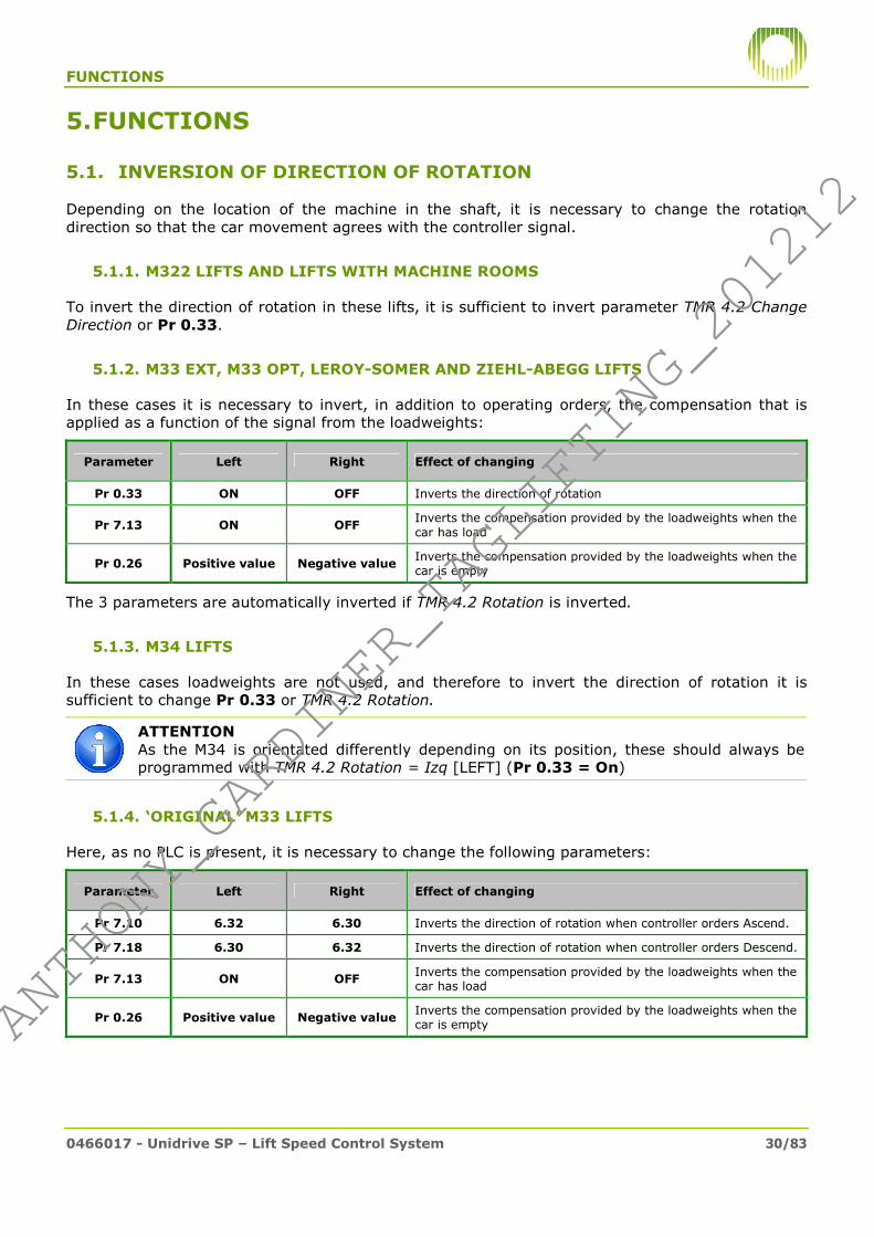
5.1. INVERSION OF DIRECTION OF ROTATION
Depending on the location of the machine in the shaft, it is necessary to change the rotation direction so that the car movement agrees with the controller signal.
5.1.1. M322 LIFTS AND LIFTS WITH MACHINE ROOMS
To invert the direction of rotation in these lifts, it is sufficient to invert parameter TMR 4.2 Change Direction or Pr 0.33.
5.1.2. M33 EXT, M33 OPT, LEROY-SOMER AND ZIEHL-ABEGG LIFTS
In these cases it is necessary to invert, in addition to operating orders, the compensation that is applied as a function of the signal from the loadweights:
Parameter Left Right Effect of changing
Pr 0.33 ON OFF Inverts the direction of rotation
Pr 7.13 ON OFF Inverts the compensation provided by the loadweights when the car has load
Pr 0.26 Positive value Negative value Inverts the compensation provided by the loadweights when the car is empty
The 3 parameters are automatically inverted if TMR 4.2 Rotation is inverted.
5.1.3. M34 LIFTS
In these cases loadweights are not used, and therefore to invert the direction of rotation it is sufficient to change Pr 0.33 or TMR 4.2 Rotation.
ATTENTION As the M34 is orientated differently depending on its position, these should always be programmed with TMR 4.2 Rotation = Izq [LEFT] (Pr 0.33 = On)
5.1.4. ‘ORIGINAL’ M33 LIFTS
Here, as no PLC is present, it is necessary to change the following parameters:
Parameter Left Right Effect of changing
Pr 7.10 6.32 6.30 Inverts the direction of rotation when controller orders Ascend.
Pr 7.18 6.30 6.32 Inverts the direction of rotation when controller orders Descend.
Pr 7.13 ON OFF Inverts the compensation provided by the loadweights when the car has load
Pr 0.26 Positive value Negative value Inverts the compensation provided by the loadweights when the car is empty
#ANTHONY_GARDINER_TAGLIFTING_201212#
ANTHONY_GARDINER_TAGLIFTING_201212

FUNCTIONS
0466017 - Unidrive SP – Lift Speed Control System 31/83
5.2. MOTOR AUTO TUNING
The auto tuning or auto adjustment process serves to calculate:
• Motor parameters (TMR 5.5.1 or 5.5.2): resistance (Pr 5.17), inductance (Pr 5.24) and:
In the case of asynchronous motors: power factor (Pr 0.43).
For synchronous motors: encoder reference angle (Pr 0.43). This parameter is fundamental for correctly controlling these motors, see section 6.3.
• Control parameters (TMR 5.6.1 or 5.6.2): Gain.P.curr (Pr 0.38) and Gain.I.curr (Pr 0.39). These parameters are very important to motor control, and the values calculated by the auto tuning tend not to be ideal, and therefore it is recommended to:
Use those indicated in this standard for that motor or a similar one.
Divide by 2 (motor up to 22kW) or 4 (motor over 22kW) the values calculated by the auto tuning where there is no data for a similar motor.
If the drive has been changed auto adjustment is not necessary (it is sufficient to copy the parameters from one to the other using the SmartCard or using the SM-Apps.Lite card reset to default parameters function).
However, auto adjustment should be carried out when:
• The motor is special and therefore its electrical parameters do not figure in the tables.
• A synchronous motor encoder has been manipulated (rotated or replaced).
5.2.1. ROTARY AUTO TUNING
To perform this auto adjustment the traction cables must be unhooked because the motor needs to be able to rotate freely. For synchronous motors, this can be attempted with a balanced load in the centre of the shaft, but the estimated angle will be imprecise. For asynchronous motors it is impossible to perform directly with cables (it takes too long and it would crash).
The rotary auto tuning process is as follows:
1. Put the lift in emergency mode.
2. If using the TM, program TMR 4.1 Type = [Rot] and Execute = [YE] If using the Keypad Plus, program Pr 0.40=2 and Pr 8.11=on (the latter should not be performed for original ‘M33’ lifts).
3. Press an emergency pushbutton (up or down) and keep it pressed until the drive finishes the auto tuning (approx. 40s). This can be observed because TMR 4.1 Status will change to inactive or the Keypad screen will display rdy.
4. Make a note of the values obtained (especially the angle) and correct the gains.
5. If Pr 8.11 has been modified, reset to off.
6. Check for correct motor operation before hanging cables. A synchronous motor should consume (Pr 0.12) less than 1A, and an asynchronous one approximately half its rated current. Record parameters and SmartCard.
If the auto tuning was performed with the Keypad Plus and it fails because the brake opens and
closes repeatedly, repeat the entire process with Pr 8.11=off and setting Pr 8.21=8.09+ in
step 2. Upon completion of the process, reset 8.21=19.46+ in step 5.
5.2.2. STATIC AUTO TUNING
This auto adjustment doesn’t need the motor to move and therefore cables don’t have to be unhooked. However, it doesn’t calculate the encoder reference angle (synchronous motors) and its power factor estimate (synchronous motors) isn’t as precise as with rotary auto tuning.
#ANTHONY_GARDINER_TAGLIFTING_201212#
ANTHONY_GARDINER_TAGLIFTING_201212

FUNCTIONS
0466017 - Unidrive SP – Lift Speed Control System 32/83
To perform static auto tuning:
1. Put the lift in emergency mode.
2. If using the TM, program TMR 4.1 Type = [est] and Execute = [YE] If using the Keypad Plus, Pr 0.40 = 4 (synchronous motor) or 1 (asynchronous).
3. Press an emergency pushbutton (up or down) and keep it pressed until the drive finishes the auto tuning (approx. 2s). This can be observed because TMR 4.1 Status will change to inact or the Keypad screen will display rdy.
4. Make a note of the values obtained and correct gains if necessary. Store parameters.
5.3. SM-APPS.LITE SPECIAL FUNCTIONS
This section describes functions that are only available due to the software contained on the SM-Apps.Lite card. If the drive did not originally include this card, it can be added to provide these functions (in the case of ‘original’ M33 lifts, the only function that can be used is reset to default parameters).
5.3.1. ANGLE ESTIMATE (ONLY SYNCHRONOUS MOTORS)
This function allows the encoder reference angle to be estimated (Pr 0.43) on a synchronous motor, in the same manner as when performing a rotary auto tuning but without having to unhook the traction cables.
A certain amount of imbalance is required for the estimate, therefore it is important to ensure that the brake opens and that the car and counterweight are not balanced (a good way of doing this is to test using manual rescue, the car moves).
To perform the angle estimate:
1. Put the lift in emergency mode with the car empty. Leave a certain distance from the edges (the process will fail if the counterweight or car rest on the buffers).
2. Set Pr 20.21 to 1
3. Press an emergency pushbutton to initiate the process.
4. During the process, the motor tends to become unstable, and therefore the drive and the lift controller report O.Spd errors. This doesn’t mean that the process has failed (these faults are automatically recovered and the process continues). The emergency pushbutton must remain pressed until the process finishes correctly (Pr 20.21 returns to 0) or the drive display shows a Tune fault (which indicates that the process has failed).
5. If the process completes correctly, Pr 20.21 returns to 0 and the lift starts to move normally. Release the pushbutton to stop.
6. Check that motor current consumption (Pr 0.12) is normal. With the car empty downwards, the value for Pr 0.12 should be approximately 80-90% of nominal motor current. To the contrary counterweight is incorrect or process has failed.
If the process fails continually with Tune or Tune2, it could be due to incorrect wiring of the output. Exchange two wires in the inverter output (for example, U and V) and try again.
This function only provides an estimate and is therefore less precise than rotary auto tuning. If in doubt, unhook the cables and perform rotary autotuning.
Having checked that the lift works perfectly with the new calculated angle, it is recommended it be phased to 0 as described in the following section.
#ANTHONY_GARDINER_TAGLIFTING_201212#
ANTHONY_GARDINER_TAGLIFTING_201212

FUNCTIONS
0466017 - Unidrive SP – Lift Speed Control System 33/83
5.3.2. ENCODER PHASING TO 0 (ONLY SYNCHRONOUS MOTORS)
This function moves the shaft of a synchronous motor to the position calculated by auto tuning (or angle estimate) above (position recorded in Pr 0.43) and phases the encoder to 0 in this position. In this manner, following execution, the angle to be set for Pr 0.43 to control that motor becomes 0.
This operation is carried out at the factory for all motors. However, if rotary auto tuning or angle estimate has been performed because the encoder has been changed or moved, phasing to 0 can also be used.
To execute this function:
1. Put the lift in emergency mode. Leave a certain distance from the edges (the process will fail if the counterweight or car rest on the buffers).
2. Set Pr 20.25 to 1
3. Press an emergency pushbutton (ascend or descend) to initiate the process.
4. During the process, the motor will move by approximately one turn to place itself in the phasing position.
5. If the process completes correctly, Pr 20.43 phases to 0, Pr 20.25 returns to 0 and the lift starts to move normally. To the contrary the drive returns a Tune fault.
Once finished, check that motor current consumption (Pr 0.12) is normal. Supposing the car is empty, use the emergency control panel to move the car down, the value for Pr 0.12 should be approximately 80-90% of nominal motor current.
5.3.3. RESET TO DEFAULT PROGRAMMING
The SM-Apps.Lite card memory contains a saved copy of default parameters for each Orona installation type.
To restore them, proceed as follows:
1. Stop the lift (place in emergency mode).
2. Program the lift type in Pr 19.14:
Type M33
original M33 ext.
M33 opt.
Leroy-Somer
Ziehl-Abegg
M34 Machine room
M322 1000rpm
M322 1500rpm
Pr 19.14 101 111 121 131 141 161 201 211 221
3. Program installation type in Pr 19.15:
Asynchronous motors with machine room Synchronous M322 Motors
Red. Susp Speed m/s
Pulley mm
Mot. Pow. (cv)
Pr 19.15 M. speed (rpm)
Persons Reg.pow (kW)
Pr 19.15
Only standard parameters, upon completion of reset, have to program motor,
speed, acceleration and jerk.
7.5 1 1000
4-6 5.5 1
10 2 8 7.5 2
15 3
1500
4-6 5.5 1
rest 4 8 7.5 2
47:2 2:1 1 600 15 5 10-13 11 3
45:1 1:1 1 570 10 6
47:2 1:1 1.6 530 15 7
45:1 1:1 1 570 7.5 8
#ANTHONY_GARDINER_TAGLIFTING_201212#
ANTHONY_GARDINER_TAGLIFTING_201212

FUNCTIONS
0466017 - Unidrive SP – Lift Speed Control System 34/83
Speed Persons Direction M33
original M33 ext. M33 opt. M34
1
4-6 Left 1 1
1 Right 2 2
8 Left 3 3
2 Right 4 4
10-13 Left 5 5
Right 6 6
16 Left 1 7
Right 2 8
21 Left 3 9
Right 4 10
1,6
4-6 Left 7 11
Right 8 12
8 Left 9 13
Right 10 14
10-13 Left 11 15
Right 12 16
16 Left 5 17
Right 6 18
21 Left 7 19
Right 8 20
Gearless Leroy-Somer Machine Gearless Ziehl-Abegg Machine
Speed Load (kg) Direction Pr 19.15
Speed Load (kg) Susp.
Pulley (mm) Direction Pr 19.15
1 2000 Right 1 1 630 1:1 318 Right 1
1.6 1425 Right 2 1 1250 1:1 318 Right 2
1.6 2000 Right 3 1 1600 2:1 318 Right 3
1.s6 2500 Right 4 1 2000 2:1 392 Right 4
1 2500 2:1 395 Right 5
1.6 1800 2:1 444 Right 6
These parameters are generally recorded at the factory for each type of installation, but it is important to check them before resetting.
4. Set Pr 0.00=1700.
5. Set Pr 19.40=on to initiate reset.
6. The reset lasts approximately 30 seconds, on completion Pr 19.40 automatically returns to off. During the process faults may arise that will reset upon completion of the process (doesn’t mean it has failed).
If after 1 minute Pr 19.40 continues at on, the process has failed. Program Pr 19.40 =
off, restart the SM-Apps.Lite card (Pr x.00=1070 + ) and restart from point 1.
7. After the resetting to default parameters, the SM-Apps.Lite card must be reset: Pr
x.00=1070 + .
8. After confirming that the lift works properly and that the programming is correct, parameters
for Pr 0.00=1000 + should be recorded.
This reset to default programming function CAN be used with M33 ‘original’ lifts (if an SM-Apps.Lite card is added to the drive).
#ANTHONY_GARDINER_TAGLIFTING_201212#
ANTHONY_GARDINER_TAGLIFTING_201212

FUNCTIONS
0466017 - Unidrive SP – Lift Speed Control System 35/83
5.3.4. FILTERING OF DIGITAL INPUTS
The controller controls the drive via 5 digital signals: 2 for direction and 3 for speed level. If due to electromagnetic problems one of these signals changes value, albeit briefly, the drive responds by starting a ramp. If this occurs near a speed change point, the lift can overrun its stop.
Using the calculation capacity of the SM-Apps.Lite card, these inputs are filtered, ignoring any change lasting less than 8ms.
5.3.5. UNIT CONVERSION
The units used by the Control Techniques drive for speed, acceleration and jerk parameters are more geared to machine tools than lifts. To better see what effect these parameters have on the car, unit conversion has been implemented in the card (from rpm to m/s).
To perform this conversion, the following input parameters are necessary (factory adjusted for most installations):
Data Keypad Plus
Suspension Pr 19.18 : Pr 19.19
Reduction Pr 19.20 : Pr 19.21
Pulley diameter (mm) Pr 19.22
(*) For example, a lift with 2:1 suspension should be Pr 19.18=2 and Pr 19.19=1…
The speed “copy” parameters in m/s are described in section 4.5.1. Copies of accelerations (m/s2) and jerks (m/s3) are described in 4.5.2. It must be borne in mind that all these “copy” parameters are read only.
5.3.6. COUNTERWEIGHT CALCULATION (ONLY GEARLESS MOTORS)
On all lifts it is essential that the counterweight is correctly setup, because otherwise there may been problems with excessive heating or even destruction of the motor, the drive or (more commonly) the braking resistances.
It is also important, especially to achieve good car comfort, that mechanical system assembly (guides, side bars, cables) is the best possible. This tends to measured by a variable called mechanical efficiency (a good value is 80% for M34 and 85% for the rest).
This function allows mechanical efficiency to be calculated approximately and how much weight needs to be added to the counterweight without having to place a balanced load in the car. This can only be used in gearless lifts.
This function requires the following parameters to be programmed (factory adjusted for most installations):
Data Keypad Plus Correct value
Suspension Pr 19.18 : Pr 19.19 1:1 for M34, 2:1 for M33 opt, variable (rest)
Reduction Pr 19.20 : Pr 19.21 1:1 in all cases (they are gearless)
Pulley diameter (mm) Pr 19.22 130 (M34), 160 (M33 opt), variable (rest)
Counterweight factor (%) Pr 19.23 45% (M34), 50% (rest)
Motor rated torque (Nm) Pr 19.24 Variable, get from rating plate
Lift rated load (kg) Pr 19.25 -
To use this function:
#ANTHONY_GARDINER_TAGLIFTING_201212#
ANTHONY_GARDINER_TAGLIFTING_201212

FUNCTIONS
0466017 - Unidrive SP – Lift Speed Control System 36/83
1. Lock the doors from the Maintenance Terminal.
2. Set the load in the car during the test (by default 0, empty car) in Pr 20.27.
3. Set Pr 20.28 to 1
4. Make 2 calls from the MT to travel the entire shaft (on up and one down, or the other way round). If a full run is not possible, an emergency manoeuvre can be performed (at lest 4 seconds each run) but measurement precision will be reduced (it is recommended that the manoeuvre be performed half way up the shaft to correct the effect of traction cable weight).
5. At the end of the second run, the function finalises and returns Pr 20.28 to 0 again and returns results for:
- Efficiency (Pr 20.30): if less than 80%, it is important that the installation be mechanically inspected (guides, guide bars, traction cables, etc.).
- Weight in kg that has to be added to the counterweight (Pr 20.31). If it is negative, remove instead of add. It is recommended that the function is run after doing so to see how it has ended up, especially if the weight entered or added is very large.
This calculation is an estimate, if in doubt the best thing is to place a balanced load in the car and measure consumption on ascent and descent, which should be approximately the same (1A difference).
5.3.7. IMPULSE TO UNWEDGE
The drive programming has been conceived to achieve a soft speed profile and good in car comfort. This programming isn’t ideal for unwedging. This function allows the drive to apply the motor with a maximum possible current impulse to try to unwedge it.
To activate this function, enter 1 for Pr 19.31. For protection, the function automatically deactivates after 120 seconds, giving a T050 fault, that must be reset.
#ANTHONY_GARDINER_TAGLIFTING_201212#
ANTHONY_GARDINER_TAGLIFTING_201212

PROBLEM SOLVING
0466017 - Unidrive SP – Lift Speed Control System 37/83
6. PROBLEM SOLVING
6.1. PROGRAMMING PROBLEMS
If there are any problems during lift start, first check that the configuration corresponds to the installation type, in accordance with the following table:
Lift type SM-
Apps.Lite?
Control Mode Pr 0.48
TMR 5.1 Mode
Basic parameters Pr 19.14
PLC status Pr 11.48
TMR 5.7.3 Status
DPL status Pr 17.03
TMR 5.7.4 Status
M33 Original NO
SERVO
101 ** 0 (no) Doesn’t exist
(NO) YES 0 (no) 2 (run)
M33 Extended NO
111 ** 2 (run) Doesn’t exist
(NO) YES 1 (stop) 2 (run)
M33 Optimized NO
121 ** 2 (run) Doesn’t exist
(NO) YES 1 (stop) 2 (run)
Gearless Leroy-Somer
NO 131 **
2 (run) Doesn’t exist (NO)
YES 1 (stop) 2 (run)
Gearless Ziehl-Abegg
NO 141 **
2 (run) Doesn’t exist (NO)
YES 1 (stop) 2 (run)
M34 NO
161 ** 2 (run) Doesn’t exist
(NO) YES 1 (stop) 2 (run)
O-170 / SASSI NO
C.L.Vector (V.L.Closed)
201 ** 2 (run) Doesn’t exist
(NO) YES 1 (stop) 2 (run)
M322 1000rpm NO
211 ** 2 (run) Doesn’t exist
(NO) YES 1 (stop) 2 (run)
M322 1500rpm NO
221 ** 2 (run) Doesn’t exist
(NO) YES 1 (stop) 2 (run)
(*) These installations never include a card, but one can be installed to provide additional functions.
(**) This parameter has only existed since April 09. If 0 (it is prior to this date), check:
Lift type Control Mode
Pr 0.48 TMR 5.1 Mode
No. Poles Pr 0.42
TMR 5.5.1 Poles
Rated Speed Pr 5.08
TMR 5.5.X rpm nom.
Encoder type Pr 3.38
TMR 5.7.1 Type
M33 Original
SERVO
12 (6) 191 or 306 SC.Hiper
M33 Extended 12 (6) 239 or 383 SC.Hiper
M33 Optimized 16 (8) 239 or 383 SC.Hiper
Gearless Leroy-Somer 32 (16) Varies SC.Endat
Gearless Ziehl-Abegg 20 (10) Varies SC.Endat
M34 16 (8) 147 SC.Hiper
O-170 / SASSI
C.L.Vector (V.L.Closed)
4 (2) 1410 – 1500 AB
M322 1000rpm 6 (3) 940 – 1000 AB
M322 1500rpm 4 (2) 1440 – 1500 AB
Having checked lift type, check programming corresponds to installation load and speed by verifying rated current and rpm in tables 4.2.2 and 4.2.3.
#ANTHONY_GARDINER_TAGLIFTING_201212#
ANTHONY_GARDINER_TAGLIFTING_201212

PROBLEM SOLVING
0466017 - Unidrive SP – Lift Speed Control System 38/83
6.1.1. Change of Control Mode
If the control mode does not correspond to that contained in the table, it must be changed. This involves resetting the control mode and programming each parameter one by one. As this operation is very laborious it is easy to commit errors, instead proceed as follows:
• Recover the parameters from a SmartCard (see section 3.3).
• Use a PC and CTSoft to record the corresponding file (ask tech. support)
• If there is an SM-Apps.Lite card reset to default parameters (5.3.3) can be used.
If the parameters on the SmartCard do not correspond to the installation either, request an SM-Apps.Lite or SmartCard from the factory indicating the type of installation.
6.1.2. Change to basic programming
If the file programmed on the drive does not correspond to the installation type:
• Recover the parameters from a SmartCard (see section 3.3).
• If there is an SM-Apps.Lite card reset to default parameters (5.3.3) can be used.
• Use CTSoft to record the corresponding file (ask at factory).
• Manually program the parameters with the values in section 9.
6.1.3. PLC deactivation
If the PLC is active (Pr 11.48=2 or TMR 5.7.3 Status = Run) and it is to be deactivated (for example because it was an M33 ARCA I, and shouldn’t have one), it can be deactivated as follows:
• Using the Keypad Plus: Pr 11.47=0
• Using the Orona MT: TMR 5.7.3 Activate = NO
If the lift is an M33 ARCA I, the PLC will have unconfigured some of the parameters, therefore
set: Pr 14.16=2.07, Pr 0.06=175, Pr 4.06=175, and record them (Pr 0.00=1000 + ).
6.1.4. PLC activation
If the lift requires PLC (that is, it isn’t an M33 original, nor does it contain an SM-Apps.Lite card) and the PLC is recorded but stopped (Pr 11.48=1 or TMR 5.7.3 Status=Stop), it can be activated:
• Using the Keypad Plus: Pr 11.47=2
• Using the Orona MT: TMR 5.7.3 Activate = YES
Check the value of the following parameters: - Pr 8.24=1.45 - Pr 8.25=1.46 - Pr 8.26=1.47 - Pr 14.16=4.07
Alter the parameters must be recorded (Pr 0.00=1000 + ).
If the PLC has not been dumped (Pr 11.48=0 or TMR 5.7.3 Activate = No), its best to recover
it from a SmartCard (Pr 0.00=6004 + ), and then activate as indicated above.
ATTENTION 1. The SM-Apps.Lite card automatically deactivates the PLC because it performs the same functions. To activate, first deactivate the DPL. 2. Never activate the PLC on M33 ‘original’
#ANTHONY_GARDINER_TAGLIFTING_201212#
ANTHONY_GARDINER_TAGLIFTING_201212

PROBLEM SOLVING
0466017 - Unidrive SP – Lift Speed Control System 39/83
6.1.5. DPL deactivation
The DPL software used by the SM-Apps.Lite card activates automatically when the card is inserted, deactivating the PLC. If the code is functioning correctly, parameter Pr 17.03=run (or TMR 5.7.4 Status=run).
If there has been a DPL fault (Pr 17.03=triP or TMR 5.7.4 Status=AV) or the DPL has a problem that cannot be recovered, it can be deactivated and operate with the PLC, as follows:
- Pr 17.13=OFF and Pr 0.00=1070 + (DPL ceases to work) - Pr 11.47=2 (to activate the PLC) - Pr 8.24=1.45 - Pr 8.25=1.46 - Pr 8.26=1.47 - Pr 14.16=2.07 (M33 original) or Pr 14.16=4.07 (rest of lifts).
- Record parameters Pr 0.00=1000 +
This allows, for example, the car to be moved to access the drive if it is in the shaft and the SM-Apps.Lite card needs to be replaced.
6.1.6. DPL activation
The DPL software used by the SM-Apps.Lite card activates automatically when the card is inserted, deactivating the PLC.
However, if the code has been manually stopped (as described in the previous point), parameter Pr 17.03=1 (or TMR 5.7.4 Status=stop). To reactivate it:
- Pr 17.13=ON
- Pr 0.00=1070 + (the PLC automatically deactivates)
- Record parameters: Pr 0.00=1000 +
Verify that the PLC has been deactivated (Pr 11.48=1 or TMR 5.7.3 Status=Stop). If not, set Pr 19.14 and Pr 19.15 to the correct value (according to section 9.1) and restart the SM-
Apps.Lite card (Pr 0.00=1070 + )
6.1.7. DPL faults
If the SM-Apps.Lite card detects a problem, execution of the DPL software is halted and the lift stops. On the Keypad Plus or TMR 1 the associated drive fault is SL3.Er (?212). To recover it,
set Pr 0.00=1070 + . If the fault persists, disable the DPL and activate the PLC (see 6.1.5).
If the fault is repetitive, obtain the value for the following parameters and consult the Technical Support Department:
Parameter Description
Pr 17.02 SM-Apps.Lite card hardware version
Pr 17.04 % of card resources used
Pr 17.50 Type of error
Pr 17.48 Code line where error detected
Pr 20.17 DPL software version
#ANTHONY_GARDINER_TAGLIFTING_201212#
ANTHONY_GARDINER_TAGLIFTING_201212

PROBLEM SOLVING
0466017 - Unidrive SP – Lift Speed Control System 40/83
6.2. DISPLAYING STATUS VARIABLES
6.2.1. STATUS OF INPUTS AND OUTPUTS
The activation and deactivation of inputs and outputs can be observed in the following menus:
Inputs and outputs
Parameter Value
Up Input TMR 3.2 Up Pr 7.01
OFF / ON 0 / 100%
Descend Input TMR 3.2 Down Pr 7.03
OFF / ON 0 / 100%
B1 Speed Level Input
TMR 3.2 Speed B1 Pr 8.04
OFF / ON 0 / 1
B2 Speed Level Input
TMR 3.2 Speed B2 Pr 8.05
OFF / ON 0 / 1
B3 Speed Level Input
TMR 3.2 Speed B3 Pr 8.06
OFF / ON 0 / 1
Loadweights Input TMR 3.2 Load Weight Pr 0.25
0 - 100%
Rescue Input TMR 3.2 Rescue Pr 0.23
OFF / ON 0 / 1
Brake Output TMR 3.2 Brake Pr 0.22
OFF / ON 0 / 1
6.2.2. GENERAL STATUS VARIABLES
The following variables can also be viewed on the MT or Keypad Plus:
Variable Parameter Value or unit Description
Selected speed level TMR 3.1 Speed ref. Pr 0.14
Vnull, V00, … Vmax 1,2… 8
Indicates the speed level selected, according to B1,B2,B3 decoding described in 4.5
Rotation speed TMR 3.1 Real Speed Pr 0.10
mm/s rpm
Engine rotation speed measured from encoder.
Power consumption TMR 3.1 Output Current Pr 0.11
tenths of A A
Marks reading of drive output current.
Secure Disable TMR 3.1 SecureDisable Pr 0.29
OFF/ ON 0 / 1
Indicates if Secure Disable (also called Baseblock) input is activated
Motor torque TMR 3.1 Torque TMR 3.1 Sign. Torque Pr 0.24
0 – 175% pos /neg ±175%
Marks the amount of torque required from the motor to move the car. The drive estimates this based on measured current.
Motor power TMR 3.1 Power
TMR 3.1 Sign.Power Pr 5.03
W
pos /neg kW
Measurement of power consumed by motor. If negative indicative of power dissipating in braking resistance.
DC bus voltage TMR 3.1 Tension BUS Pr 0.13
V Drive BUS DC voltage.
Mode TMR 3.1 Mode Pr 0.48
V.L.Closed / SERVO CL Vect / SERVO
Drive control mode.
Software TMR 3.1 Software Pr 0.50
- Drive firmware version
Subsoftware TMR 3.1 Subsoftware Pr 11.34
- Drive firmware sub-version
Encoder position TMR 3.1 Enc. Position Pr 3.29
0 - 65535 Encoder position (only if absolute)
#ANTHONY_GARDINER_TAGLIFTING_201212#
ANTHONY_GARDINER_TAGLIFTING_201212

PROBLEM SOLVING
0466017 - Unidrive SP – Lift Speed Control System 41/83
6.3. PERMANENT MAGNET SYNCHRONOUS MOTORS
For most applications without machine rooms permanent magnet synchronous motors are being used, which work at low speed, allowing gearing to be eliminated. This translates in less machine volume and weight and more comfortable and silent operation.
These motors are comprised of a fixed part (stator) with the coils and a mobile part (rotor) with magnets that is joined to the motor pulley. In applying current to the coils, a magnetic field is created that drags the magnets and the rotor with them.
However, for the motor to rotate it is necessary that the current (and with it the magnetic field) is created in the same position the magnets are orientated towards. If they loose synchronisation, the motor cannot provide torque and will be dragged by the load (with the drive reporting fault Enc10).
For the motor to start this means: • A drive that has been prepared to control this type of motor must be used. It is not
sufficient to apply power direct from the power supply. • The drive needs to use an absolute encoder to be aware of the shaft position at all times, to
know where it should apply current to the coils. • Given that the encoder mounts manually, an operation is required (called auto tuning or
reference seeking) so that the drive can calculate the encoder mounting position.
Reference seeking (auto tuning):
The auto tuning operation allows the drive to calculate the position of the motor magnets with in relation to encoder position 0 (reference). This value is saved in parameter Pr 0.43 (TMR 5.5.2 Angle). This operation is carried out at the factory for all motors.
To avoid this parameter having a different value for each motor, an operation called phasing to 0 is also conducted at the factory, which consists of resetting encoder position 0 to the magnet position. Thereby, any motor phased to 0 can be controlled by a drive with Pr 0.43 (TMR 5.5.2 Angle) set to 0 as long as phases U, V, W are respected.
This phasing to 0 operation has been possible since the M33 optimized entered production, and therefore only the M33 ‘original’, M33 extended (plus those where an encoder or phase sequence has been changed followed by an auto tuning) require reference angle to be other than 0.
Section 5.2.1 describes how to perform an auto tuning. If an SM-Apps.Lite card is present, the position can be phased to 0 after auto tuning, as described in 0.
ATTENTION: THE FOLLOWING IS FUNDAMENTAL TO GUARANTEE ITS OPERATION:
• Protect the encoder cable, removing it as far as possible from the power cables and avoiding cutting or extending it. If electromagnetic noise penetrates this signal, he motor will have problems.
• Never dismount the encoder. The encoder is joined to the motor shaft on one side and the machine casing on the other. If either were to move in relation to their fastenings, an auto tuning would be needed to recalculate the angle.
• Never change phases. Check that phases U,V,W coincide on the drive and the motor and correct if necessary. It is not sufficient to respect the order, U on the drive must coincide with U on the motor, V on the drive with V on the motor… To invert the direction of rotation on the motor, use the functions described in 5, never invert the phase order.
#ANTHONY_GARDINER_TAGLIFTING_201212#
ANTHONY_GARDINER_TAGLIFTING_201212

PROBLEM SOLVING
0466017 - Unidrive SP – Lift Speed Control System 42/83
6.4. FREQUENT PROBLEMS
This section describes some of the most frequent problems and provides advice on how to resolve them. Before referring to this section, it is important to check that the basic drive programming corresponds to the type of installation, as contained in table 6.1.
It is also very frequent that problems are due to poor apparatus counter weighting or poor mechanical efficiency. If the drive has an SM-Apps.Lite card, an estimate is possible as described in 5.3.6. Otherwise, a half load should be inserted in the car and the current consumption measured (Pr 0.12) in both directions. It should be the same in both directions and less than 70% of the rated value (geared asynchronous motors) or 20% (gearless).
Short-circuit on output (OI.AC)
The drive reports an OI.AC fault when it detects a current peak in excess of 225% above the motor rated value. As software limits current to 175%, this fault can only occur if there is a short-circuit at the power output (U,V,W) or motor control is lost (normally due to a problem with the encoder in synchronous motors). To attempt to see where the problem resides, we recommend:
• Attempting a static auto tuning (no need to unhook cables): in synchronous motors an angle error could produce this fault (although it is not common). If static auto tuning doesn’t produce a fault, check “Angle problems (synchronous motors)”. If it continues to report an error, continue with this section.
• Bridge contactors: run motor cables direct to drive, respecting the sequence U,V,W. In so doing a short-circuit in the contactor cable can be ruled out, or even a fault with one of its poles.
• Eliminate the short-circuit cable-set: in gearless lifts, motor phases are taken to the control panel where a contactor shorts them during the rescue operation. By removing the cable-set this avoids there a problem arising here.
• Check motor cable-set: measure the resistance between phases and ground with a Multimeter, although the value will vary a lot depending on motor power, it should always exceed 0.3 ohms.
If cabling and customisation errors have been ruled out, it is probably a motor coil insulation fault. Check with an insulation meter, and replace the motor if necessary.
Overload at output (IT.AC)
To avoid the motor overheating, the drive reports an IT.AC fault if the output current exceeds the rated value (Pr 0.46) during a certain period (which is shorter the greater the current). This section describes what to look at if the motor starts to move (if it doesn’t, consult the previous point) but this fault appears after a period of time.
• Rated current: check that Pr 0.46 (TMR 5.5.X Curr.nom) is correctly programmed (according to the tables in 4.2.2 and 4.2.3).
• Counterweight: ensure that the apparatus is properly counterweighted. If the lift is gearless and has an SM-Apps.Lite card, carry out a test as described in 5.3.6. If not half a load has to be inserted in the car and check that current consumption in both directions is similar (approximately 60% of rated motor current for asynchronous motors and 20% for synchronous).
• Efficiency: check that installation is mechanically correct: guide alignment, lubrication, traction cabling tensioning, pulleys, gearing, pulley friction brake, etc.
• Encoder angle (synchronous motors): if the encoder has moved or the angle (Pr 0.43) is poorly set, the motor looses torque. If the error is substantial the drive reports other faults (motor looses control), but if it is small this fault can be produced (the drive is capable of controlling the motor but having lost torque requires more current).
#ANTHONY_GARDINER_TAGLIFTING_201212#
ANTHONY_GARDINER_TAGLIFTING_201212

PROBLEM SOLVING
0466017 - Unidrive SP – Lift Speed Control System 43/83
The motor doesn’t move
The motor doesn’t rotate or starts moving and stops shortly thereafter. Some errors can be produced such as IT.AC. Check in the following order:
• Control signal activation: check that SecureDisable, Ascend/Descend, speed level signals are correctly activated (see 6.2.1). In M33 original ARCA I lifts, if the speed levels do not activate, the brake micro switches may be faulty.
• That the drive is not disabled: ensure Pr 6.15=1. • That torque is not limited:
- M33 original: torque limits (Pr 4.05, Pr 4.06 and Pr 0.06) should be set to 175%. Also check that Pr 14.16=2.07
- Rest of lifts: when the lift starts the torque limit (Pr 0.06) should increase from 0 to 175%. If it doesn’t, check that the PLC or DPL are active (see 6.1) and that Pr 0.58=175. If no SM-Apps.Lite card, check that Pr 14.16=4.07.
• Check output cabling: check that the 3 phases (U,V,W) arrive at the motor correctly. Perform a static auto tuning (if it produces an RS fault then one or more phases are probably not arriving, fix cabling). If it is a permanent magnet motor, perform checks in section on “Angle problems (synchronous motors)”.
• That brake output activates: the brake should activate (see 6.2.1) in accordance with the normal operating sequence. With asynchronous motors, if it does not activate check that current (Pr 0.12 or TMR 3.1) increases above half rated (if it doesn’t there may be a problem with the motor output cabling).
• That the brake opens electronically: use a Multimeter to check that voltage reaches the coils (Attention: on m33 ‘original’, m33 extended and Leroy-Somer lifts voltage measurements using a Multimeter will give strange readings, although it will be possible to see if there is some voltage). Another way of checking it is to see if the brake-micro switch status changes (if present). If they don’t open, check cabling, coils and brake disk.
• That the brake disk or machine have not seized up: attempt to perform rotary auto tuning (not necessary to remove cables), if it reports a tune1 fault (which means that the shaft cannot rotate during the auto tuning) this is probably the problem. This may be due to the brake having become stuck (has occurred in some M33 optimized where the machine has been exposed to a very damp environment) or to excessive wear in gears, bearings, etc. Consult Authorised Technical Support.
• That the encoder reads the speed: check that when the shaft moves, that the encoder measures the speed (Pr 3.27 and Pr 0.10). If either does not see speed, check menu 3, encoder cabling and assembly. On synchronous motors RFC mode can be activated (see section 4.12) to operate provisionally without encoder and see if there problem lies there.
Load overwhelms motor (synchronous magnet motors):
If on opening the brake, the car is always dragged by the counterweight, the motor is not providing sufficient torque. It will probably be accompanied by fault Enc10, IT.AC.
It is recommended trying in each direction and mid-shaft, leaving a few seconds to make sure there are no loadweight adjustment problems or that the direction of rotation is inverted. Check in the following order:
• That the drive is not disabled: ensure parameter Pr 6.15=1. • That torque is not limited:
- M33 original: current limits (Pr 4.05, Pr 4.06 and Pr 0.06) should be set to 175%. Check that Pr 14.16=2.07
- Rest of lifts: when the lift starts the current limit (Pr 0.06) should increase from 0 to 175%. If it doesn’t, check that the PLC or DPL are active (see 6.1) and that Pr 0.58=175. If no SM-Apps.Lite card, check that Pr 14.16=4.07.
• That there is power in the motor: can be seen in Pr 0.12 or TMR 3.1 Current. If 0, this means there is an output connection error or the contactor doesn’t go in.
• That the motor is not feed to 2 phases: check the output cabling, attempt a static auto tuning (if it produces an RS fault then one or more phases are probably loose).
#ANTHONY_GARDINER_TAGLIFTING_201212#
ANTHONY_GARDINER_TAGLIFTING_201212

PROBLEM SOLVING
0466017 - Unidrive SP – Lift Speed Control System 44/83
• Ensure counterweight is correct: if the counterweight is very badly constructed, the motor may not have sufficient torque to retain the car. Test inserting more load in the car.
• Perform checks in section “Angle problems (synchronous motors)”.
Load overwhelms motor (asynchronous motors):
If on opening the brake, the car is always dragged by the counterweight, the motor is not providing sufficient torque. It will probably be accompanied by fault O.SPd or IT.AC. Check in this order:
• That the drive is not disabled: ensure parameter Pr 6.15=1. • That torque is not limited: current limit (Pr 0.06) should increase from 0 to 175% when
the lift starts. If it doesn’t, check that the PLC or DPL are active (see 6.1) and that Pr 0.58=175.
• That there is power in the motor: can be seen in Pr 0.12 or TMR 3.1 Current. If 0, this means there is an output connection error or the contactors doesn’t go in.
• Ensure counterweight is correct: if the counterweight is very badly constructed, the motor may not have sufficient torque to retain the car. Test inserting more load in the car.
Angle problems (synchronous motors) – Fault Enc10
The drive reports an Enc10 fault when it detects that is loosing control over a synchronous motor. This tends to occur when there is a problem with the angle or the encoder.
If the fault is constant (as soon as motor is started), check:
• Output phases: check that phases U,V,W correctly arrive from the drive to the motor without crossing.
• Encoder cabling: check encoder cabling for cuts, remove from power cables as far as possible.
• Encoder angle: check that Pr 0.43 or TMR 5.5.2 Enc.Angle has that correct value (0 in the majority of cases).
• Encoder mechanical assembly: ensure that the fixed part of the encoder doesn’t slide in relation to the rear machine cover.
• Recalculate encoder angle: an angle estimate can be produced if the drive has an SM-Apps.Lite card, if not traction cables will have to be removed and a dynamic auto tuning performed.
If the fault occurs occasionally, especially during abrupt stops (for example with the inspection operating panel), check:
• Encoder cabling: check encoder cabling for cuts, remove from power cables as far as possible.
• Encoder mechanical assembly: ensure that the fixed part of the encoder doesn’t slide in relation to the rear machine cover.
• Program an auto reset: as described further on.
Counter movement on start
The lift works OK, but there is counter movement on start or it is slightly dragged by the load (if it touches a limit stop it stops). If it shifts or seems to loose control, consult “Load overwhelms motor”.
This may be due to the drive not controlling the brake relay (in which case the brake enters and drops with the controller contactors, and therefore when the brake opens there is no current in the motor and the load overwhelms).
If this is happening, it is probably also accompanied by a bump on stop. Check that Pr 0.22 (or TMR 3.2 Brake) change to 0 on arrival at the floor before the controller removes the contactors. If it doesn’t, check Pr 8.21=19.46 (on m33 original, must be Pr 8.21=9.02). If it does, check rtf relay cabling and brake disk.
#ANTHONY_GARDINER_TAGLIFTING_201212#
ANTHONY_GARDINER_TAGLIFTING_201212
PROBLEM SOLVING
0466017 - Unidrive SP – Lift Speed Control System 45/83
It can also be the case that the motor does not have sufficient current when the brake is opened. To discount it, increase Pr 0.51 (TMR 5.4.1 Open brake T) by 500ms and Pr 0.53 (TMR 5.4.1 T start travel) by 0.5s and see if it disappears. Observe if Pr 0.06 reaches 175% before the brake output is activated, if not reduce Pr 0.52 (or TMR 5.4.1 Torque T).
If the motor shifts on start but then stops and remains at speed 0 (despite having a speed set point), it is probably at 2 phases (consult “Motor doesn’t move”).
It may be due to the loadweights being poorly configured (in lifts that use them). To verify this:
• Activate the position control (Pr 0.57=1 or TMR 5.4.4 Position Control = YES). If the problem persists, it is not due to the loadweights, consult “Load overwhelms motor”.
• Check that the loadweight measures correctly. Input (Pr 0.25 or TMR 3.2 Loadweight) should be 0% with car empty and approx. 100% with full load. If it isn’t, loadweights must be configured properly.
• For Orona loadweights, check that Cancel Weighing = NO in menu 4.3 of the loadweight device. Also check the version (Menu 4.6.1 of Loadweight device), it should 1.0 or later (update if not).
• For Micelect loadweights, check that internal bridges J1 and J2 are in position 2-3. • Check the weight parameters (TMR 3.2 or using the Keypad Plus Pr 0.26, Pr 0.27, Pr 7.10
and Pr 7.13) are those that correspond for the installation. If they are ok, try simply inverting it changing TMR 5.4.4 Sign.Comp. (or, if using the Keypad Plus, invert Pr 7.13 and the sign for Pr 0.26).
• If there is still counter movement, recalibrate the weight as described in 4.9.2.
Bumps on arriving at floor
May be due to:
• Controller disconnecting contactors too soon: extend the contactor drop period (MT Control 5.3.3).
• The drive stops applying current too soon: extend the contactor drop period and the travel stop time (Pr 0.55 or TMR 5.4.1).
• The brake drops when the motor hasn’t stopped yet. Increase the brake closing time (Pr 0.23 for m33 original, TMR 5.4.1 or Pr 0.54 for the rest) and contactor drop time.
• The drive doesn’t control the brake relay (the brake enters and drops with the controller contactors). If this is happening, it is probably also accompanied by a shift on start. Check that Pr 0.22 (or TMR 3.2 Brake) change to 0 on arrival at the floor before the controller removes the contactors. If it doesn’t, check Pr 8.21=19.46 (on m33 original, must be Pr 8.21=9.02). If it does, check rtf relay cabling and brake disk.
• The car overruns the floor because the motor doesn’t stop in time: check deceleration, jerk and floor approximation speed parameters.
Controller faults 345 and 346
In optimized M33, M34, Nuevo Renova and gearless Leroy-Somer or Ziehl-Abegg lifts the controller reads the status of each brake via the micro switches. The majority of cases only have 2 brakes (MT Control 5.3.4.3 Controller FR = [C_2]) but in Leroy-Somer machines there can be 3 or 4 brakes ([C_3] or [C_4]).
In m33 ‘original’ and extended lifts, there is just one reading and both contacts in series (MT Control 5.3.4.3 Control FR = [C_1]). M33 ARCA I lifts did not read the brake micro switches (although they did cut speed signals, see 0451118).
In gearless Leroy-Somer lifts, the contacts are normally closed instead of open, and therefore should be programmed MT Control 5.3.4.3 Logica.Ent.FR = [N_C]. In the rest it should be [N_O].
Micro switch activation and deactivation can be seen in MT Control, 3.5.1 (attention, the logic of inputs E7, E8 and E9 is contrary to that of E6):
• Input E6: micro 1 (or both micros in series for M33 original and extended) • Input E9: micro 2
#ANTHONY_GARDINER_TAGLIFTING_201212#
ANTHONY_GARDINER_TAGLIFTING_201212

PROBLEM SOLVING
0466017 - Unidrive SP – Lift Speed Control System 46/83
• Input E7: micro 3 (only in Leroy-Somer machines with 3-4 brakes) • Input E8: micro 4 (only in Leroy-Somer machines with 4 brakes)
If fault 345 appears, try to move in emergency (which ignores contact status). If the car doesn’t move, the brake probably isn’t opening, consult “The motor doesn’t move”. If the brake does open and the car moves, check that the base plate inputs are activated. If they fail, change the brake micros. If they manage to activate but despite this there are still occasional faults, extend the time T.Ret.FR.
If fault 346 appears on arriving at the floor, check that the readings are deactivated. If they don’t, check or change the brake micro switches. If they change, but the lift bumps on stop, extend the contactor drop period (MT Control 5.3.3) at 5d and travel stop time (Pr 0.55 or TMR 5.4.1) at 500m. If the bump and/or fault 346 occur occasionally, proceed in the same manner (increasing both times).
The motor doesn’t reach the speed it should – Controller slipping faults (804)
If controller slippage faults occur, check if the motor actually reaches the speed it should reach or if there is a detection problem (with the speed limiter encoder).
See motor speed with Keypad Plus (Pr 0.10 in rpm). Can also be seen with TMR 3.1 Real Speed, but in mm/s (calculation made). If it reaches its correct speed according to table 4.5.1, check the detection levels set for the controller (MT Control 5.3.2). Use the speed reading function (MT Control 4.3.3) to see if the encoder reads properly from the speed limiter.
If there are occasional errors, slightly reduce the parameter associated with MT Control 5.3.2: for example, if an optimized M33 every so often gives approximation speed slipping errors, reduce 5.3.2 V0 from 7c to 6c.
If the motor doesn’t reach the speed it should, check:
• Speed parameter programming (according to tables in 4.5). • That the drive is reading the reference properly indicated by the control (TMR 3.1 Ref.
Speed or Pr 0.14 as indicated in 4.5.1). • That the number of poles is correct. Special attention to M322 (4 poles 1500rpm motors and
6 poles 1000rpm motors). • Rated speed from rating plate: doesn’t relate to a 1m/s motor for a 1.6m/s installation, etc. • That voltage isn’t saturated (synchronous motors): with descending empty car, check
that voltage (Pr 5.02 or TMR 3.1 Voltage) does not reach the rated value programmed for Pr 0.44 or TMR 5.5.2 Voltage nom. (which should always be 390). If not, check the counterweight and if it persists consult Technical Support Service.
Also note that the control gives an approximation speed set point when it is beyond end magnets CO and CU. There may be a problem with these magnets or the direction of rotation.
The lift overruns the travel stop (on all trips)
Check speed, acceleration, deceleration and jerk parameters according to tables in 4.5.1 and 4.5.2. The jerk can be increased for stronger deceleration (although comfort will be reduced, it is preferable to changing acceleration and deceleration).
Check the deceleration distances programmed in MT Control 5.4.3.1 (type II/III positioning) or the placement of speed change screens CS/CB (type I positioning). Increase them if necessary.
Check the apparatus counterweight and the state of the braking resistance.
The lift overruns the travel stop (occasionally) – 2336 Anomalies
The drive overruns the travel stop occasionally, probably due to electromagnetic noise problems in the CAN bus (which tend to produce 2236 control anomalies).
• Check programming for Pr 2.04 = Fast. • Check the cabling layout, attempting to follow the advice in 6.6.
#ANTHONY_GARDINER_TAGLIFTING_201212#
ANTHONY_GARDINER_TAGLIFTING_201212

PROBLEM SOLVING
0466017 - Unidrive SP – Lift Speed Control System 47/83
• Place resistances at the control signal inputs to make the more robust vis-à-vis emissions, as indicated in 2.3.
• Use a Gateway panel to insulate the bus from the power panel (consult with Technical Support Service).
If the problem occurs at the ends on start, it may be due to poor loadweight reading which provokes a small counter movement and touches the limit stop. Activate position control to see if it disappears.
th or thS fault
This fault is due to the drive having a poorly programmed digital input (Pr 7.15 is set to th instead of Volt). Given that the default Control Techniques programming is Pr 7.15=th whilst the configuration used by Orona is Pr 7.15=Volt, this fault tends to occur when the drive has been reset to the Control Techniques default parameters (in which case the entire drive will have to be reprogrammed).
It is recommended to check the drive programming according to table 6.1. If the programming is bad, the parameters will have to be recovered from the SmartCard or from SM-Apps.Lite. If the
other parameters are ok and just the fault has to be recovered, program Pr 7.15=Volt, press
and record parameters (Pr 0.00=1000 + ).
Some of the parameters on menu 0 have strange values or are not accessible (Keypad Plus)
The parameters in menu 0 are copies of parameters from other menus to make them more easily accessible.
Review the control mode (Pr 0.48). If it is bad, recover parameters from the SmartCard or SM-Apps.Lite.
Check the parameters for menu 11 and 22:
Pr 11.01=3.01 Pr 11.02=4.01 Pr 11.03=5.05 Pr 11.04=1.50 Pr 11.05=1.22 Pr 11.06=1.23 Pr 11.07=1.24 Pr 11.08=1.25 Pr 11.09=1.28 Pr 11.10=18.27 [*] Pr 11.11=18.01 [8.02**] Pr 11.12=8.01 Pr 11.13=8.03 [9.09**]
Pr 11.14=4.03 Pr 11.15=7.02 [4.08**] Pr 11.16=4.09 Pr 11.17=7.12 Pr 11.18=3.42 Pr 11.19=8.09 Pr 11.20=11.42 Pr 22.01=11.33 Pr 22.02=11.32 Pr 22.03=18.40 [no**] Pr 22.04=18.45 [11.30**] Pr 22.05=11.24 Pr 22.06=11.25
Pr 22.07=11.23 Pr 22.10=5.12 Pr 22.11=5.18 Pr 22.18=11.31 Pr 22.20=11.29 Pr 22.21=19.12 [no**] Pr 22.22=14.07 [no**] Pr 22.23=12.47 [no**] Pr 22.24=12.46 [no**] Pr 22.25=19.13 [no**] Pr 22.26=12.48 [no**] Pr 22.27=19.49 [no**] Pr 22.28=18.11 [no**] Pr 22.29=18.12 [no**]
(*) This parameter is worth 2.13 on M33 originals and 2.17 on M33 extended or asynchronous motors (M322 and Machine Room)
(**) These parameters had this other value for M33 originals (or didn’t exist).
Check that the Keypad Plus firmware version (Pr 40.02) is not 04.04.00, 04.04.01, 04.04.02, 04.04.03. These versions can cause problems when modifying parameters on menu 0: a different parameter is modified from the correct one, for example:
- When modifying Pr 0.17 value Pr 8.26 is modified instead of Pr 1.24
- When modifying Pr 0.19 value Pr 7.11 is modified instead of Pr 1.28
If you have one of these versions, consult the Technical Support Service. Versions 04.04.04 and later do not exhibit this problem.
#ANTHONY_GARDINER_TAGLIFTING_201212#
ANTHONY_GARDINER_TAGLIFTING_201212

PROBLEM SOLVING
0466017 - Unidrive SP – Lift Speed Control System 48/83
Motor noise and/or vibrations
These problems may be caused by the drive control or by mechanical problems with the installation (poor guide alignment, wear, poorly aligned or tensioned traction cables, pulleys jumping, etc.).
Check first that parameter Pr 0.06 does not oscillate during motor operation (should remain constant at 175% as indicated in the graphics for sequence 4.4.1). Check:
• M33 original lifts: Pr 14.06=2.07 • Rest of lifts without SM-Apps.Lite card: Pr 14.06=4.07 • Rest of lifts with SM-Apps.Lite card: Pr 14.06=0
Also check hat he PLC or DPL are working according to table in 6.1. If necessary, the DPL can be deactivated and it can operate with the PLC to rule out card problems.
If the motor is asynchronous, RFC mode can be activated (see 4.12) to rule out encoder assembly problems.
Check that the following parameters are programmed as stipulated:
• Asynchronous motor: TMR 5.5.1 Current nom. (Pr 0.46), Poles (Pr 0.42), rpm nom (Pr 5.08), Power fact. (Pr 0.43).
• Synchronous motor: TMR 5.5.2 Current nom. (Pr 0.46), Poles (Pr 0.42), rpm nom. (Pr 5.08).
• Encoder: TMR 5.7.1 type (Pr 3.38), lines (Pr 3.34), Tension alim. (Pr 3.36). • Speed control: TMR 5.4.2 Gain P. (Pr 0.07), Gain I. (Pr 0.08), enc. filter (Pr 0.28). • Current control: TMR 5.6.x Gain.P.curr. (Pr 0.38), Gain.I.curr. (Pr 0.39), Filter curr. (Pr
4.12).
Check that indicated motor parameters coincide with the rating plate, if not make a note of original values and program parameters according to plate. Attempt to perform a static auto tuning (see 5.5.2) to calculate new control gains.
If the problems persist, the control loops can be retouched but be aware that these adjustments are delicate. Lock the doors and always test without anyone in the car and with the stop button within hands reach, because the motor may become unstable and damage the installation.
Change the current (Pr 4.12 or TMR 5.6.X Curr. Filter) and speed (Pr 0.28 or TMR 5.4.2 Enc. filter) reading filters according to the following table:
Parameter Test 1 Test 2 Test 3 Test 4 Test 5 Test 6 Test 7 Test 8 Test 9
Current filter 0ms 0ms 1ms 1ms 1ms 2ms 2ms 4ms 4ms Encoder filter 0 2 0 1 2 0 2 0 2
If it is still not resolved, return to original setting and try:
• If the motor makes noise even when empty (no cables), try changing the current control parameters.
• If oscillations are noted in the car or motor, try changing the speed control parameters.
The best way of evaluating the behaviour of these parameters is to use a PC and the CT-Scope tool to chart:
• Motor current (Pr 4.02) against required torque (Pr 4.03). Attempt to adjust current control parameters to avoid oscillations in the chart or excessive noise in the motor.
• Motor speed (Pr 3.02) against reference speed (Pr 3.01). Having ensured there are no current jumps, the speed loop parameters can be changed to see there are not oscillations in this chart.
• Attention to the in-car effect of these parameters: good tracking of set point speed does not guarantee good in-car comfort (the oscillation may be due to other parts of the mechanical system).
#ANTHONY_GARDINER_TAGLIFTING_201212#
ANTHONY_GARDINER_TAGLIFTING_201212

PROBLEM SOLVING
0466017 - Unidrive SP – Lift Speed Control System 49/83
There are also tools (e.g. SOINDAR) that allow the oscillations produced in-car to be measured and later analysed to determine what could be the cause of the oscillations. Consult Technical Support Service.
Not all parameters visible or units not correct (using the Orona MT)
Check the MT version in Menu 2.8.1 MT Functions. Should be 8.0 or above.
If communication is via loadweight plate, also check the version in Menu 4.6.1 of the Loadweight device. Should be 1.10 or above.
Fault Oht4.P
This fault indicates excess temperature in the input rectifier. Can only occur in size 4 or larger drives. If it were to occur sporadically independent of load, could be a problem with noise in the temperature reading, in which case place 2 330nF 500V condensers in parallel between DC+ and GND (can be requested from Control Techniques, reference 1691-0006-02). Another option is to program an auto-reset (see further on).
If it occurs only under severe traffic conditions, check the counterweight and attempt to reduce the switching frequency (Pr 0.41 or TMR 5.6.X).
Cannot modify parameters
Check that parameter Pr 0.49 is at L2. If when attempting to modify a parameter the screen displays CODE, this means that a code has been entered by mistake to block parameter access. To unlock:
1. Turn off the drive.
2. Turn it on whilst pressing the blue button and the down arrow on the joypad.
3. Make a note of the code that appears for parameter Pr 0.34.
4. When CodE appears on the console, enter the code (Pr 0.34).
5. Lastly, modify parameter Pr 0.49=LOC L2 (Access to all menus).
Differential jumps (occasionally)
Check the connections for the ground cables. Check input power cabling. Measure insulation from ground for input power cabling and motor cabling with insulation meter (disconnecting main switch so there is no power).
If problems persist, substitute the differential for one with high immunity.
Auto reset
If the drive presents a sporadic fault which doesn’t appear to prejudice the operation of the device, an auto reset can be programmed (so that you do not always have to recover it).
#ANTHONY_GARDINER_TAGLIFTING_201212#
ANTHONY_GARDINER_TAGLIFTING_201212
PROBLEM SOLVING
0466017 - Unidrive SP – Lift Speed Control System 50/83
To do so, configure parameter Pr 10.34 = 2 (to attempt two fault recoveries) and Pr 10.35 = 5 (5 seconds between retries). If the fault persists after 2 retries, the drive will stop attempting to recover from it and will remain faulty.
Problems with the SmartCard using the Orona MT
Loadweight board software versions 0.80 and earlier can have problems reading and recording from the SmartCard. It is recommended to update them to the latest version using the MT.
Speeds/accelerations/jerks displayed on TMR don’t make sense
The TMR converts the values from the drive (rpm) to show them in mm/s (a simpler and more logical unit of measurement to use in a lift).
To do so, it equals the rated speed for the lift installation (data that is recorded in the controller, but can be consulted in TMR 5.5.1 Rated speed) with:
- Synchronous motors: Pr 5.08 (motor rated speed)
- Asynchronous motors: Pr 0.02 (maximum speed)
If the values displayed for speeds, accelerations and jerks don’t seem to make sense, use the Keypad Plus to check them, because the parameters actually used by the drive are in rpm.
Check the version of the Maintenance Terminal (8.0 or later) and loadweight board (1.10 or later), because in previews versions these parameters were in centimeters/second instead of milimeters/second.
#ANTHONY_GARDINER_TAGLIFTING_201212#
ANTHONY_GARDINER_TAGLIFTING_201212

PROBLEM SOLVING
0466017 - Unidrive SP – Lift Speed Control System 51/83
6.5. DRIVE FAULTS
When the drive has a fault, the name appears in the Keypad Plus. If we have TM the name of the last fault can be seen in menu 1 (only the most frequent, the rest are marked as ?XXX, with XXX being the fault code).
With the fault name or code, the following table can be used to establish its cause and how to go about trying to resolve it:
Fault and code Possible cause Possible solutions
cL2
28
Analogue input 2 is poorly configured Check Pr 7.11. Can be due to a problem with the Keypad Plus (see Frequent Problems)
cL3
29
Analogue input 3 is poorly configured Check Pr 7.15.
CL.bit
35
Programming error Check that Pr 6.43 = 0
ConF.P
111
Programming error Check that Pr 11.35 = 0
dESt
199
Two or more parameters attempting to write the same parameter.
Programming Pr 0.00 = 12001 only parameters causing the problem will be visible. Correct them.
EEF
31
Corrupt memory data Reset drive to default Control Techniques parameters (Pr 0.00=1233 + ), recover parameters from an SM-Apps.Lite or SmartCard and record parameters
Enc1
189
Encoder fault: supply overload Check encoder supply voltage (Pr 3.36) and encoder cabling. If asynchronous, switch to RFC (see 4.12) and disconnect encoder.
Enc2
190
Encoder fault: cable cut Check Pr 3.36 and encoder cable. Change encoder cable. If it persists, change the encoder. On asynchronous motors, RFC mode can be activated (see 4.12)
Enc3
191
Encoder fault: phase fault during movement
Find breaks in encoder cable. Remove as far as possible from power cables. If it persists, change cable and/or encoder.
Enc4
192
Encoder fault: communication fault Check Pr 3.36 and encoder cable. Change encoder cable. If it persists, change the encoder.
Enc5
193
Encoder fault: checksum error Check encoder cable and replace it.
Enc6
194
Encoder fault: encoder detects a problem Replace the encoder.
Enc7
195
Encoder fault: initialization fault Check encoder parameters (Pr 3.36, Pr 3.38) and encoder cabling. If it persists, change cable and/or encoder.
Enc8
196
Encoder fault: initialization fault on start Check encoder parameters (Pr 3.36, Pr 3.38) and encoder cabling. If it persists, change the encoder.
Enc9
197
Encoder fault: customization fault Check that Pr 3.26 = 0
Enc10
198
Encoder fault: SERVO phase fault If it occurs during normal operation, encoder angle poorly programmed Pr 0.43. Check U,V,W phase sequence. Perform a rotary auto tuning (no cables) or angle estimate. If it only happens on sudden braking, simply recover the fault by pressing reset.
Enc11
161
Encoder fault: Sin/Cos signal fault Check encoder cable.
#ANTHONY_GARDINER_TAGLIFTING_201212#
ANTHONY_GARDINER_TAGLIFTING_201212

PROBLEM SOLVING
0466017 - Unidrive SP – Lift Speed Control System 52/83
Enc12
162
Encoder fault: encoder Hyperface initialization fault
Check encoder parameters (Pr 3.36, Pr 3.38) and encoder cabling. If it persists, change the encoder.
Enc13
163
Encoder fault: Endat encoder initialization fault (wrong number of turns)
Check encoder parameters (Pr 3.36, Pr 3.38) and encoder cabling. If it persists, change the encoder.
Enc14
164
Encoder fault: Endat encoder initialization fault (excessive number of turns)
Check encoder parameters (Pr 3.36, Pr 3.38) and encoder cabling. If it persists, change the encoder.
Enc15
165
Encoder fault: customization error Check Pr 5.36=0. If it persists, replace cable and/or encoder.
Enc16
166
Encoder fault: initialization error (periods/revolution)
Check encoder type (Pr 3.36, Pr 3.38) and encoder cabling. If it persists, change the encoder.
Enc17
167
Encoder fault: supply overload Check encoder supply voltage (Pr 3.36) and encoder cabling. If it persists, replace it
ENP.Er
176
Error in executing encoder data recovery function
Reset the fault and program the data manually.
Et
6
Fault activated from digital input Program Pr 0.00 = 12001, find what parameter has a value of 10.32 and program to its correct value.
HF01-13 Hardware fault Replace the drive
HF26
226
Hardware fault Check braking resistance connection. If it persists, replace the drive.
HF17 - 32
217 – 232
Hardware fault Replace the drive
It.AC
20
Overload at motor output Consult section on Frequent Problems (6.4)
It.Br
19
Braking resistor overload. Check apparatus counterweight. If it is correct, increase Pr 10.30 (TMR 5.7.2 T.Resist.Frein)
L.SYnC
39
Programming error Check that control mode (Pr 0.48) is not REGEN. Recover default parameters (using the SM-Apps.Lite or Smartcard).
O.CtL
23
Excess temperature of control plate Check that fans work and that ambient temperature is not excessive. Reduce switching frequency (TMR 5.6.X or Pr 0.41)
O.ht1
21
Power state excess temperature (in thermal model simulation)
Check lift counterweight. Reduce switching frequency (TMR 5.6.X or Pr 0.41)
O.ht2 ó Oht2.P
22 or 105
Radiator excess temperature Check that fans work and that ambient temperature is not excessive. Reduce switching frequency (TMR 5.6.X or Pr 0.41)
O.ht3
27
Drive excess temperature (in thermal model simulation)
Check that fans work and that ambient temperature is not excessive. Reduce switching frequency (TMR 5.6.X or Pr 0.41)
Oht4.P
102
Rectifier excess temperature Consult section on Frequent Problems (6.4)
OI.AC o OIAC.P
3 or 104
Output short-circuit Consult section on Frequent Problems (6.4)
OI.br o OIbr.P
4 or 103
Braking resistance short-circuit Check braking resistance cabling. Check ohms value for resistance with Multimeter. Measure ground insulation for resistance terminals.
OIdC.P
109
Short-circuit in IGBTs Measure insulation of output and motor cables.
O.Ld1
26
Overload or short-circuit of 24V power supply.
Check control terminal cabling. If ARCA, disconnect RAA and RTF relays to see if it disappears. For M33 opt, check cable-sets JM1 and JM2, above all that JM2-6 (rtf) is not crossed with JM2-(0V).
#ANTHONY_GARDINER_TAGLIFTING_201212#
ANTHONY_GARDINER_TAGLIFTING_201212

PROBLEM SOLVING
0466017 - Unidrive SP – Lift Speed Control System 53/83
O.SPd
7
Excess speed The speed reading exceeds Pr 0.02 by 120%. If it occurs during travel, check the programming of this parameter. If the speed has not reached this value, check encoder mechanical assembly. If produced because the load overwhelms the motor, consult the section on Frequent Problems (6.4).
OV o OV.P
2 or 106 Excess voltage in DC Bus Check braking resistance cabling and ohms (with the
Multimeter). Check counterweight and deceleration (Pr 0.04).
Check input voltage (L1,L2,L3).
Check motor insulation.
PAd
34
Programming error Check Pr 1.14=Pr so that drive controlled from digital signals.
PH o PH.P
32 or 107 Input voltage imbalance Check input voltage (L1,L2,L3), when car moves
downwards. Check input cabling. Program Pr 6.47=1. If it persists, activate auto reset.
PS o PS.P
5 or 108 Error in internal power source If additional cards inserted, remove them and attempt to
recover faults. If they recover, replace card with new one. If not, replace the drive.
PS.10V
8
10V output cabling error (terminal 4) Check that no cable connected to terminal 4.
PS.24V
9
Excessive consumption internal 24V supply Check digital input/output cabling.
SAVE.Er o PSAVE.Er
36 or 37
There has been a power cut whilst recording parameters
Simply warns that the changed parameters may have not been correctly saved. Recover it, check parameters and save again.
SCL
30
485 communication error 485 communication fault. Check RJ-45 cable. Replace Keypad Plus.
th o thS
24 or 25 Digital input configuration error Consult section on Frequent Problems (6.4)
Unid.P
110
Internal drive connection error Replace the drive
UV
1
DC bus voltage below 350V (because L1,L2,L3 input below 250Vac).
Tends to occur whenever voltage removed. If it occurs during normal operation, check L1,L2,L3 input voltage with empty car descending (should be 380-415Vac). If it occurs during a rescue, check the status of the automatic VR. Ensure CEM contactor activates. Check SAI cabling and 220/380 transformer.
The following errors can only occur during auto tuning:
Fault and code
Cause Possible solutions
tunE
18
Auto tuning manually stopped before finishing
Control has probably disconnected the contactors, removing Secure Disable signal. Recover fault and repeat auto tuning.
tunE1
11
Auto tuning fails because speed not read from encoder.
Can be due to an encoder fault or shaft hasn’t rotated (because cables not removed or brake not opened).
tunE2
12
Auto tuning fails because motor rotation does not correspond to encoder rotation.
Check U,V,W sequence. If its OK and the fault persists, exchange 2 phases.
tunE3
13
Encoder signals fail Check encoder cabling. Replace cable and/or encoder.
tunE4,5,6
14, 15, 16
Incorrectly configured encoder Check encoder parameters. If it persists, change cable and/or encoder.
tunE7
17
Rotation speed doesn’t coincide with theoretical.
Check number of poles and encoder parameters.
#ANTHONY_GARDINER_TAGLIFTING_201212#
ANTHONY_GARDINER_TAGLIFTING_201212

PROBLEM SOLVING
0466017 - Unidrive SP – Lift Speed Control System 54/83
rS
33
Stator resistance too great (or circuit open) Should only occur if one or more drive output phases not reaching motor. Check contactor cabling.
SmartCard usage errors:
Fault and code
Possible cause Possible solutions
C.Acc
185
Cannot read/write to SmartCard Check SmartCard correctly inserted. Replace SmartCard
C.boot
177
Incorrect parameter form writing attempt Never program Pr 11.42 = 3 (auto) or 4 (boot)
C.bUSY
178
Cannot access SmartCard because it is being accessed from another location.
Repeat the operation. If it persists, disconnect additional cards, and retry.
C.Chg
179
The SmartCard is not empty Repeat deletion operation (Pr 0.00=9999 + )
C.Cpr
188
SmartCard data doesn’t coincide with parameters
Recover by pressing
C.dAt
183
SmartCard doesn’t contain the data that is being attempted to be recovered
Insert SmartCard with data
C.Err
182
SmartCard data is corrupt Check SmartCard correctly inserted.
Replace SmartCard
C.Full
184
The SmartCard is full. Use another SmartCard
C.Optn
180
SmartCard data corresponds to different optional cards.
Recover faults and check parameters for menu 17.
C.Prod
175
SmartCard data is not compatible Delete the SmartCard ( Pr 0.00 = 9999 + )
Replace SmartCard
C.Rdo
181
SmartCard data is write protected Remove protection ( Pr 0.00 = 9777 + )
C.rtg
186
SmartCard data is not compatible Delete the SmartCard ( Pr 0.00 = 9999 + )
Replace SmartCard
C.TyP
187
SmartCard data is not compatible Delete the SmartCard ( Pr 0.00 = 9999 + )
Replace SmartCard
PLC errors
Fault and code
Possible cause Possible solutions
UP ACC
98
Access fault on recording PLC PLC could not be recorded because drive was enabled. Put the lift in emergency mode and retry.
UP div0
90
The PLC tries to divide by 0 Should never occur. Recover PLC from a SmartCard
UP OFL
95
The PLC takes up too much space in memory
Should never occur. Recover PLC from a SmartCard
UP ovr
94
The PLC attempts to write a value above the max. for a parameter
Should never occur. Recover PLC from a SmartCard
UP PAr
91
PLC attempts to write to non-existent parameter
Recover parameters and PLC from a SmartCard.
UP ro
92
PLC attempts to write to read only parameter
Should never occur. Recover PLC from a SmartCard
UP So
93
PLC attempts to read a parameter that is read only
Should never occur. Recover PLC from a SmartCard
#ANTHONY_GARDINER_TAGLIFTING_201212#
ANTHONY_GARDINER_TAGLIFTING_201212

PROBLEM SOLVING
0466017 - Unidrive SP – Lift Speed Control System 55/83
UP udF
97
Indeterminate PLC error Should never occur. Recover PLC from a SmartCard
UP uSEr
96
PLC program forces the drive to stop. Should never occur. Recover PLC from a SmartCard
The following errors relate to additional cards, such as the SM-Apps.Lite. The X that appears in the fault code stands for a 1, 2 or 3 depending on the slot where the card is installed. Fault codes also differ depending on the slot.
Fault and code Possible cause Possible solutions
SLX.Er
202,207,212
The SM-Apps card in slot X has detected a fault
Check section 0
SLX.HF
200,205,210
Hardware fault for SM-Apps.Lite card in slot X
Check card installation. If it persists, replace it.
SLX.nF
203,208,213
The SM-Apps card in slot X has been removed
Informational only. Recover faults and record parameters.
SL.rtd
215
Internal SM-Apps card error Reset fault. If it persists, consult Technical Support Service.
SLX.tO
201,206,211
The Watchdog for the card in slot X has overflowed
Should not occur (watchdog not used). Check that Pr 17.18=0. Recover fault.
SLX.dF
204,209,214
An SM-Apps card has been changed in slot X (one model for another)
Informational only. Recover faults and record parameters.
The following errors are provoked by the DPL code on the SM-Apps.Lite card when it detects a problem with lift operation:
Fault and code
Possible cause Possible solutions
t049
49
Drive doesn’t have a PLC recorded and is attempting to perform operation 5004 (Record PLC to Smartcard)
If it is an M33 original it doesn’t need a PLC, but other installations should have this program recorded, if this is not the case obtain a Smartcard from the factory.
t050
50
Time has elapsed for unwedging the device (2 minutes)
If more than 2 minutes are needed to unwedge, when this period has elapsed Pr 19.31 (Activation unwedging mode) should be reset to 1.
t055
55
The protection against winding of the ropes has actuated
Increase the protection torque (Pr 19.16) or disable the protection (Pr 19.32=0)
#ANTHONY_GARDINER_TAGLIFTING_201212#
ANTHONY_GARDINER_TAGLIFTING_201212

PROBLEM SOLVING
0466017 - Unidrive SP – Lift Speed Control System 56/83
6.6. CABLING ADVICE
All electrical equipment emits electromagnetic signals and is susceptible to being affected by electromagnetic radiation. A frequency drive in particular, because of the way it works, is a piece of equipment that can emit electromagnetic radiation affecting other equipment.
This electromagnetic emission can be transmitted by cables (conducted) or by air (radiated). Cable layout can amplify emission levels, and therefore it is essential that the installation be arranged according to ORONA criteria. It is equally important that the accessories used by the drive are defined in the ORONA product.
6.6.1. ELECTROMAGNETIC EMISSION REDUCTION ELEMENTS
• Input filter. Electrically installed prior to the drive and located as close to it as possible. The connection cable between the filter output and the drive input should be as short as possible. Earths should be connected. The filter should not be bridged.
• Output ferrite. The drive output power cable, prior to the contactors, contains a ferrite around which each of the three power conductors is wound 3 times (2 in the case of the M34).
• Motor power cable. This is a shielded cable, with good quality shielding (covering > 85%). The shield is fixed to earth at each end, using metallic clasps that fasten most of the shield surface.
• Motor rescue cable (only synchronous motors). This is a shielded cable, with good quality shielding (covering > 85%). The shield is fixed to earth at each end, using metallic clasps that fasten most of the shield surface. In future this shielded cable may not be so if Steward type 28B1531-000 ferrite is used with three cable turns (or similar characteristics).
• Braking resistance cable. This cable is also shielded (like the motor power cable) and has similar characteristics. The cable should also be fixed to ground and both ends. Must be as short as possible.
• Supply cable for brakes with overexcitation. With this equipment, used only on M33 ‘original’, M33 extended y gearless Leroy-Somer machines, the cable has to be shielded and fixed to ground at each end.
• Motor encoder cable. This cable is shielded and its ground connections are made internally. This cable is today installed along with a Steward (or similar) ferrite 28A2025-OA0.
• Load resistances, drive inputs. 1kOhm resistances are placed on all drive inputs which act as a load and immunize against the coupling of damaging signals in these cables.
6.6.2. CRITERIA FOR CORRECT CABLING
• Use of shielded metallic cable-sets for all cables with a power noise signal (motor, synchronous motor rescue, over-excited brakes, braking resistance). Connected to shielding at each end.
• If running in parallel, the noise cables should be separated at least 30 cm from other channels.
• Assemble sot that conductors or cables that carry different classes of signal cross each other at right angles, particularly in the case of sensitive and noisy signals.
#ANTHONY_GARDINER_TAGLIFTING_201212#
ANTHONY_GARDINER_TAGLIFTING_201212

PROBLEM SOLVING
0466017 - Unidrive SP – Lift Speed Control System 57/83
• Free or unused conductors in a cable should be systematically connected to ground (chassis, channelling, cabinet, etc. ) at each end.
6.6.3. CABLING LAYOUT DIAGRAMS
• M34 0461466
• M33 optimized: 0461432 and 0461437
• M33 ‘original’ and extended: 0461404
• Gearless Ziehl-Abegg: 0461459, 0461461 and 0461463
• Gearless Leroy-Somer: 0461440, 0461442 and 0461444
• M322: 0461406
• With machine room: 0461424
Having started the installation, we can make an indirect measurement that tells us if the installation has been correctly performed. We should verify, using the Maintenance Terminal, for the near total absence of error messages in the bus after various car travels.
6.6.4. EXAMPLES OF POOR CABLING LAYOUT
WHAT’S WRONG WITH IT?
• The encoder cable and motor power supply cable run together, they should be separated by at least 300 mm if they run parallel.
• The cable, on arrival at the panel, forms a long loop before passing through the ferrite. Cables should be a short as possible and not have loops.
BRAKING RESISTANCE CABLE-SET
WHAT’S WRONG WITH IT?
• It isn’t shielded.
• It’s long.
• The cable is looped (power emission).
• It runs parallel to the filter cable.
#ANTHONY_GARDINER_TAGLIFTING_201212#
ANTHONY_GARDINER_TAGLIFTING_201212

PROBLEM SOLVING
0466017 - Unidrive SP – Lift Speed Control System 58/83
6.6.5. EXAMPLES OF GOOD CABLING LAYOUT
WHAT’S WRONG WITH IT?
This capacitor is incompatible with the external filter. It must be removed.
WHAT’S WRONG WITH IT?
The filter ground cable should be connected to the drive’s ground terminal.
WHY IS THIS OK?
Metallic clip fixes shielding to chassis (ground). Covering > 180º.
#ANTHONY_GARDINER_TAGLIFTING_201212#
ANTHONY_GARDINER_TAGLIFTING_201212

PROBLEM SOLVING
0466017 - Unidrive SP – Lift Speed Control System 59/83
The following image displays an example of how to layout cabling in an M33 Optimized lift, separating power, short-circuits and encoder cables as much as possible:
6.6.6. ELECTROMAGNETIC COMPATIBILITY REGULATIONS
By following the advice above, the installations should give no problems at all. It has been demonstrated in accredited labs:
• That, emissions levels from ORONA installations are within the levels set by Standard EN 12015.
• That, immunity levels from ORONA installations are within the levels set by Standard EN 12016.
Compliance with the standard is an important guarantee. However, there may be installations, where due to their special characteristics there is a problem with:
• Poor ground connections.
• Very sensitive radio/audio equipment installed near the lift. There are particularly sensitive radio frequencies.
In such cases, special intervention from the Technical Support Service can be sought.
Short-circuit cable-set separated from rest of cables
Shielding to ground
Cables cross 90º
Motor connections separated from rest of
cables
Shielding to ground
Cables cross 90º
Encoder cable-set separated from power cable
Short resistance connection
#ANTHONY_GARDINER_TAGLIFTING_201212#
ANTHONY_GARDINER_TAGLIFTING_201212

INDEX OF ELECTRICAL DIAGRAMS
0466017 - Unidrive SP – Lift Speed Control System 60/83
7. INDEX OF ELECTRICAL DIAGRAMS
Controller type
Machine type
Lift type Diagram type
Options Diagram code
ARCAI Gearless M33 original Power No rescue 0451117
With rescue 0451129
Control and series of safeties 0451118
ARCA II Gearless M33 original
M33 extended
Power No rescue 0461011
With rescue 0461016
Control and series of safeties 0461012
M33 optimized
Ziehl-Abegg
Power No rescue 0461051
With rescue 0461052
Ziehl-Abegg > 22kW 0461099
Control and series of safeties 0461053 / 61
Leroy-Somer Power No rescue 0461059 / 60
Control and series of safeties 0461053 / 61
Nuevo Renova Eléctrico
Power No rescue 0461094 / 88 *
With rescue 0461095 / 89 *
Control and series of safeties 0461096 / 90 *
M34 Power No rescue 0461703
With rescue 0461704
Control and series of safeties 0461707
Geared. M322 Power No rescue 0461017
With rescue 0461018
Control and series of safeties 0461019
Machine room
O-170 & SASSI
Power No rescue, brake 205V 0461027
With rescue, brake 205V 0461028
No rescue, brake 60V 0461029
With rescue, brake 60V 0461064
No rescue, ecobreak 0461049
With rescue, ecobreak 0461065
Control and series of safeties 0461033 / 34
(*) Lift without/with compensating measures
#ANTHONY_GARDINER_TAGLIFTING_201212#
ANTHONY_GARDINER_TAGLIFTING_201212

REPLACEMENT PARTS
0466017 - Unidrive SP – Lift Speed Control System 61/83
8. REPLACEMENT PARTS
8.1. EQUIPMENT REPLACEMENT
Drive programming varies depending on the installation, and therefore if a new drive is installed (requested as a replacement or using a code from another installation) the programming will not correspond to what’s required for that particular installation.
8.1.1. Using the SmartCard
The simplest way of performing the replacement is to use the SmartCard to copy the programming from the old drive to the new one. Once the new equipment has been installed, insert the SmartCard from the old machine and recover its programming:
• If it is an M33 ‘original’ (doesn’t require PLC): Pr x.00=6001 +
• In all other cases: Using TMR 4.4 Inverter -> SM = YES
Using the Keypad Plus: Pr x.00=6004 + and Pr x.00=6001 + If the new drive has an SM-Apps.Lite card, parameter Pr 19.14 and Pr 19.15 should be programmed according to the type of installation (see section 9). After programming these values,
the drive and SM-Apps.Lite card must be reset: Pr x.00=1070 + .
After doing this, the basic equipment configuration must be checked against the table in section 6. Also the value of the following parameters must be checked:
• If the drive doesn’t have an SM-Apps.Lite card: Pr 8.24=1.45; Pr 8.25=1.46; Pr 8.26=1.47; Pr 14.16=2.07 (M33 originals) or 4.07 (all other lifts).
• If the drive has an SM-Apps.Lite card: Pr 8.24=0; Pr 8.25=0; Pr 8.26=0; Pr 14.16=2.07 (M33 originals) or 0 (all other lifts).
Test for correct lift operation and record parameters. It’s a good idea to record a copy of the new programming (with parameters Pr 19.14 and 19.15) on the SmartCard.
8.1.2. Recovering default parameters
If the new drive has an SM-Apps.Lite card, an installation's default parameters can be recovered as described in section 5.3.3. When the process is finished, check for correct lift operation and record parameters.
8.2. ADDING AN SM-APPS.LITE CARD
An SM-Apps.Lite card can be added to any drive to enjoy its additional features. To do so, parameters Pr 19.14 and Pr 19.15 must first be programmed with the values for the installation
type (see section 9.1) and the parameters recorded (Pr 0.00 =1000 + ).
Once programmed, switch off the power to the drive, wait approximately one minute and insert the card. When supplying the drive with power it will report a fault (to indicate that a card has been
added). Reset the fault and the SM-Apps.Lite card by programming Pr 0.00 =1070 + .
Having checked that the lift works correctly, record the parameters. It is advisable to record a copy of the new programming (with values for Pr 19.14 and 19.15) on the SmartCard.
#ANTHONY_GARDINER_TAGLIFTING_201212#
ANTHONY_GARDINER_TAGLIFTING_201212

REPLACEMENT PARTS
0466017 - Unidrive SP – Lift Speed Control System 62/83
8.3. REPLACEMENT CODES
8.3.1. M233 Lifts
MOTOR CURRENT (A) DRIVE FILTER RESISTANCE FERRITE
In > In =<
0 12 SP 2401 5123512
5123518.01
100 ohm 520W 5118213.01
5123520 12 16
SP 2402 5123513
75 ohm 780W 5118213.02
16 25 SP 2403 5123514
50 ohm 1040W 5118213.03
5123520
8.3.2. Lifts with machine rooms
MOTOR CURRENT (A) DRIVE FILTER RESISTANCE FERRITE
In > In =<
0 12 SP 2401 5123512
5123518.01
100ohm 520W 5118213.01
5123520 12 16’8 SP2402 5123513
75ohm 780W 5118213.02
16,8 24,2 SP 2403 5123514
5123518.02 50ohm 1040W 5118213.03
24,2 32 SP 3401 5123515
5123519
40ohm 1560W 5118213.04
5123521 32 37,8
SP 3402 5123560
32ohm 4800W 5118213.05
37,8 47,2 SP 3403 5123561
27ohm 4800W 5118213.06
47,2 55,2 SP 4401 5123559
5123569 20ohm 6000W 5118213.07
8.3.3. M33 original lifts (ARCA I)
MOTOR CURRENT (A) DRIVE FILTER RESISTANCE FERRITE
In > In =<
0 12 SP 2401 5123512
5123518
PR 80ohm 1200W 5118203
5123520 12 16 SP 2402 5123513
PR 50 ohm 2000W 5118202
16 24 SP 2403 5123514
PR 40 ohm 3000W 5118204
24 31 SP 3401 5123515 5123519
PR 30 ohm 4500W 5118205
5123521
#ANTHONY_GARDINER_TAGLIFTING_201212#
ANTHONY_GARDINER_TAGLIFTING_201212

REPLACEMENT PARTS
0466017 - Unidrive SP – Lift Speed Control System 63/83
8.3.4. M33 original and extended lifts (ARCA II)
MOTOR CURRENT (A) DRIVE FILTER RESISTANCE FERRITE
In > In =<
0 12 SP 2401 5123512
5123518.01
80 ohm 1200W 5118203
5123520 12 16,8 SP 2402 5123513
50 ohm 2000W 5118202
16,8 24,2 SP 2403 5123514 51235118.02
40 ohm 3000W 5118204
24,2 32 SP 3401 5123515
5123519
30 ohm 4500W 5118205
5123521 32 37,8
SP 3402 5123560
25 ohm 7000 w 5118207
37,8 47,2 SP 3403 5123561
20 ohm 8000 w 5118208
5123521
8.3.5. M33 optimized lifts
MOTOR CURRENT (A) Auton.
rescue DRIVE FILTER RESISTANCE FERRITE
In > In =<
0 9 NO SP 1406
5123607 5123608 80 ohm 1200W 5118203
5123520
YES SP 2401 5123512
5123518.01 50 ohm 2000W 5118202
9 12
YES/NO
12 15,6 SP 2402 5123513
15,6 23,6 SP 2403 5123514
5123518.02
40 ohm 3000W 5118204
23,6 26,6 SP 2404 5123516
30 ohm 4500W 5118205
26,6 30,3 SP3401 5123515
5123519
30 ohm 4500W 5118205
5123521 30,3 37,8 SP3402 5123560
25 ohm 7000W 5118207
37,8 43,5 SP3403 5123561
20 ohm 8000W 5118208
8.3.6. M34 Lifts
MOTOR CURRENT (A) DRIVE FILTER RESISTANCE FERRITE
In > In =<
0 7,5 SP 1405 5123629
5123608
80 ohm 1200 W 5118007.01
5123520 7,5 8,5
SP 1406 5123607
8,5 9,5 60 ohm 2000 W 5118007.03
#ANTHONY_GARDINER_TAGLIFTING_201212#
ANTHONY_GARDINER_TAGLIFTING_201212

REPLACEMENT PARTS
0466017 - Unidrive SP – Lift Speed Control System 64/83
8.3.7. Gearless Leroy-Somer and Ziehl-Abegg lifts
MOTOR CURRENT (A) DRIVE FILTER RESISTANCE FERRITE
In > In =<
0 23,6 SP 2403 5123514
5123518.02
30 ohm 3000 W 5118162
5123520 23,6 26,6
SP 2404 5123516
30 ohm 4500 W 5118163
26,6 30,3 SP 3401 5123515
5123519
30 ohm 6000 W 5118164
5123521
30,3 37,8 SP 3402 5123560
25 ohm 6000 W 5118165
37,8 43,5 SP 3403 5123561 20 ohm 12000 W
5118166 43,5 56,8
SP 4401 5123559
5123569 56,8 68
SP 4402 5123586
15 ohm 12000 W 5118167
8.3.8. Encoders
• Lift with machine room (O-170, SASSI): Heidenhain ROD436 incremental encoder (5102510). This encoder includes a 10m cable that can be directly connected to the drive.
• M322: Heidenhain ERN430 incremental encoder (5102461). This encoder includes a 3m cable that can be directly connected to the drive.
• M33 ‘original’ and M33 extended: absolute Stegman SRS50 encoder with splinted shaft (4101131). Needs a cable (see below).
• M33 optimized, Nuevo Renova and M34: absolute Stegman SRS50 encoder with conical shaft (4101102). Needs a cable (see below).
• Leroy-Somer and Ziehl-Abegg machines: Heidenhain absolute encoder. No code. Consult Technical Support Service.
8.3.9. Encoder cables
• Stegman absolute encoder connection cables (include pluggable encoder connector at one end and drive at the other):
a. M33 ‘original’, extended, optimized (2.5m): 5102339.01
M34 (4.5m): 5102339.02
• Heidenhain incremental encoder extension cable (include pluggable drive connector at one end and Phoenix at the other): 9460615.02 (7m) or 9460615.01 (specifying length if not 7m).
• Heidenhain absolute encoder extension cable for Ziehl-Abegg machines: 9460675.02 (9m) or 9460675.01 (specifying length if not 9m).
• Generic encoder extension cable: includes 2 Sub-D15 connectors (one male and the other female). In this manner any cable to be plugged into the drive which doesn’t reach can be extended. 4m (9460664)
#ANTHONY_GARDINER_TAGLIFTING_201212#
ANTHONY_GARDINER_TAGLIFTING_201212

0466017 - Unidrive SP – Lift Speed Control System 65/83
8.3.10. Other elements
• SmartCard: 5123517
• KeypadPlus Console: 5123537
• SM-Apps.Lite card: 5123587
• SM-I/O Plus card: 5123594 (only used in M33 ARCA I which has had a motor modernised to M33 optimized)
• RJ45 communication cable (to join the drive to the KeypadPlus, the Base plate or the Loadweights): 5102538.01 (0.5m), 5102538.01 (1.3m), 5102351 (5m) and 5102352 (10m).
8.3.11. Communication with PC
This section briefly describes some of the programmes that enable the drive to communicate with a PC. They are not necessary but can be useful for performing advanced maintenance operations.
They all require the following cables (not coded but can be directly requested from Control Techniques with these references):
Serial port: CT SERIE COMMS CABLE (CT Part No. 4500-0087)
USB port: CT USB COMMS CABLE (CT Part No. 4500-0096)
The programmes are (can be downloaded free of charge directly from www.controltechniques.com):
• CTSoft: read and write drive parameters. Also includes the WinFlasher too, that can be used to record SM-Apps.Lite cards.
• SyptLite: read and write drive PLC software.
• CTScope: displays up to 4 drive parameters as if using an oscilloscope.
#ANTHONY_GARDINER_TAGLIFTING_201212#
ANTHONY_GARDINER_TAGLIFTING_201212

DEFAULT PARAMETERS
0466017 - Unidrive SP – Lift Speed Control System 66/83
9. DEFAULT PARAMETERS
9.1. INSTALLATION TYPES
The programming of each drive is customised at the factory for each installation. From April 2009 2 parameters (Pr 19.14 and Pr 19.15) determine how the drive is programmed. These parameters are also used for the Reset to default parameters function (if there is an SM-Apps.Lite card, see section 5.3.3).
9.1.1. LIFT TYPE
Defined in parameter Pr 19.14. Possible types are:
Type M33
original M33 ext.
M33 opt.
Leroy-Somer
Ziehl-Abegg
M34 Machine room
M322 1000rpm
M322 1500rpm
Pr 19.14 101 111 121 131 141 161 201 211 221
9.1.2. INSTALLATION TYPE
Defined in parameter Pr 19.15. The range of values depends on the type of lift:
9.1.2.1. M33 ORIGINAL, EXTENDED, OPTIMIZED AND M34
Speed Persons Direction M33 original
M33 extend.
M33 opt. M34
1 m/s
4-6 Left 1 1
1 Right 2 2
8 Left 3 3
2 Right 4 4
10-13 Left 5 5
Right 6 6
16 Left 1 7
Right 2 8
21 Left 3 9
Right 4 10
1.6 m/s
4-6 Left 7 11
Right 8 12
8 Left 9 13
Right 10 14
10-13 Left 11 15
Right 12 16
16 Left 5 17
Right 6 18
21 Left 7 19
Right 8 20
#ANTHONY_GARDINER_TAGLIFTING_201212#
ANTHONY_GARDINER_TAGLIFTING_201212

DEFAULT PARAMETERS
0466017 - Unidrive SP – Lift Speed Control System 67/83
9.1.2.2. GEARLESS LEROY-SOMER AND ZIEHL-ABEGG
Leroy-Somer Ziehl-Abegg
Speed
Load (kg) Direction
Pr 19.15
Speed Load (kg)
Susp. Pulley (mm)
Direction Pr 19.15
1 2000 right 1 1 630 1:1 318 right 1
1.6 1425 right 2 1 1250 1:1 318 right 2
1.6 2000 right 3 1 1600 2:1 318 right 3
1.6 2500 right 4 1 2000 2:1 392 right 4
1 2500 2:1 395 right 5
1.6 1800 2:1 444 right 6
9.1.2.3. GEARED ASYNCHRONOUS MOTORS
With machine room (O-170/SASSI) M322
Supp. Susp Speed m/s
Pulley (mm)
Mot.pow. (cv)
Pr 19.15
Mot.sp. (rpm)
Persons Reg. pow. (kW)
Pr 19.15
Basic programming, motor parameters, speed,
acceleration and jerk are manually programmed
7.5 1 1000
4-6 5.5 1
10 2 8 7.5 2
15 3
1500
4-6 5.5 1
rest 4 8 7.5 2
47:2 2:1 1 600 15 5 10-13 11 3
45:1 1:1 1 570 10 6
47:2 1:1 1,6 530 15 7
45:1 1:1 1 570 7.5 8
9.2. PARAMETER LISTS FOR EACH INSTALLATION
The following pages contain the basic parameters for menu 0 for the different types of installations described in the previous section. It is important to remember that the parameters in menu 0 are copies of parameters contained in other menus (which are indicated in brackets).
Also included are references to the location of these parameters in the TMR.
#ANTHONY_GARDINER_TAGLIFTING_201212#
ANTHONY_GARDINER_TAGLIFTING_201212

DEFAULT PARAMETERS
0466017 - Unidrive SP – Lift Speed Control System 68/83
M322 BASIC PARAMETERS
Pr Description TMR Value
0.00 (x.00) Function execution parameter - 0
0.01 (1.07) Minimum speed reference - 0 0.02 (1.06) Maximum speed reference See table
0.03 (2.11) Acceleration 5.3 Acceleration See table
0.04 (2.21) Deceleration 5.3 Deceleration See table
0.05 (1.14) Reference type selector - Pr
0.06 (4.07) Output current limit - Read only
0.07 (3.10) Speed loop Gain P 5.4.1 Gain P. 0.12 120m
0.08 (3.11) Speed loop Gain I 5.4.1 Gain I. 0.10 10c
0.09 (3.12) Speed loop Gain D - 0
0.10 (3.02) Encoder speed reading 3.1 Real Speed Read only
0.11 (3.01) Speed reference - Read only
0.12 (4.01) Current consumed by motor 3.1 Output Current Read only
0.13 (5.05) DC bus voltage. 3.1 Tension BUS Read only
0.14 (1.50) Selected speed level 3.1 Speed Ref. Read only
0.15 (1.22) Isoleveling speed 5.2 V00 See table
0.16 (1.23) Floor approximation speed 5.2 V0 See table
0.17 (1.24) Inspection speed 5.2 Vinsp See table
0.18 (1.25) Intermediate speed V1 5.2 V1 See table
0.19 (1.28) Maximum Speed 5.2 Vmax See table
0.20 (2.17) Jerk during travel 5.3 Jerk travel See table
0.21 (18.01) Favourable direction for rescue - Read only
0.22 (8.01) Brake relay output status 3.2 Brake Read only
0.23 (8.03) Rescue mode input state 3.2 Rescue Read only
0.24 (4.03) Torque demand on motor 3.1 Torque & sign.
Torque Read only
0.25 (7.02) Loadweights reading level (%) 3.2 Loadweight Read only
0.26 (4.09) Compensation with empty lift 5.4.4 Compensation 0
0.27 (7.12) Loadweights adjustment 5.4.4 Adjustment 1
0.28 (3.42) Speed reading filter 5.4.2 Enc. filter 1 ms
0.29 (8.09) Secure Disable input reading 3.1 Secure Disable Read only
0.30 (11.42) SmartCard functions parameter See section 3.3 0
0.31 (11.33) Drive rated voltage - Read only
0.32 (11.32) Drive rated current - Read only
0.33 (18.40) Change rotation direction See section 5 See table
0.34 (18.45) Rescue in favourable direction 5.4.3 Load favour. dir. 1
0.35 (11.24) Serial communication protocol - rtu
0.36 (11.25) Serial communication speed - 19200
0.37 (11.23) Serial communication node no. - 1
0.38 (4.13) Current loop Gain P 5.6.1 Gain.P.curr. See table
0.39 (4.14) Current loop Gain I 5.6.1 Gain.I.curr. See table
0.40 (5.12) Start auto tuning See section 5.2 0
0.41 (5.18) Switching frequency 5.6.1 Conm.freq. 8 kHz
0.42 (5.11) No. motor poles 5.5.1 Poles See table
0.43 (5.10) Motor power factor 5.5.1 Power fact. 0
0.44 (5.09) Motor rated voltage 5.5.1 Voltage nom. 380
0.45 (5.08) Motor rated speed 5.5.1 rpm nom. See table
0.46 (5.07) Motor rated current 5.5.1 Current nom. See table
0.47 (5.06) Motor rated frequency - 50.0
#ANTHONY_GARDINER_TAGLIFTING_201212#
ANTHONY_GARDINER_TAGLIFTING_201212

DEFAULT PARAMETERS
0466017 - Unidrive SP – Lift Speed Control System 69/83
0.48 (11.31) Operating Mode 3.1 Mode CL_VECT
0.49 (11.44) User safety - L1
0.50 (11.29) Drive software version 3.1 Software Read only
0.51 (19.12) Brake opening delay 5.4.1 Open Brake T 200
0.52 (14.07) Torque ramp time 5.4.1 Torque T 0
0.53 (12.47) Profile start delay 5.4.1 Trip Start T 0.5 5d
0.54 (12.46) Brake drop delay 5.4.1 Brake Fall T 0.3 3d
0.55 (19.13) Torque signal delay 5.4.1 Trip End T 200
0.56 (12.48) Deactivate drive delay - 0.5
0.57 (19.49) Position control 5.4.4 Position control 1
0.58 (18.11) Torque limit (normal operation) 5.6.2 Torque limit 175
0.59 (18.12) Torque limit (rescue mode) 5.4.3 Torque limit 60
The following parameters vary depending on the motor:
Lift type 4-6p
1000rpm 8p
1000rpm 4-6p
1500rpm 8p
1500rpm 10-13p
Pr 5.07 TMR 5.5.1 Current nom.
10.7 107d
13.2 132d
9.1 91d
12.5 125d
23.2 232d
Pr 0.42 TMR 5.5.1 Poles
6 3
4 2
Pr 0.45 TMR 5.5.1 rpm nom 946 950 1445 1440 1440
Pr 0.43 TMR 5.5.1 Power fact.
0.767 767m
0.749 749m
0.775 775m
0.856 856m
0.855 855m
Pr 0.38 TMR 5.5.1 Curr.P.gain
176 168 148 146 112
Pr 0.39 TMR 5.5.1 Curr.I.gain
865 748 773 676 460
Pr 0.02 TMR 5.6.1 Max Rpm 1039 1545 1535
Pr 0.15 TMR 5.2 V00
30 29m
45 29m
45 29m
Pr 0.16 TMR 5.2 V0
80 77m
120 78m
120 78m
Pr 0.17 TMR 5.2 Vinsp
600 577m
900 583m
900 586m
Pr 0.19 TMR 5.2 Vmax
1000 962m
1500 971m
1500 977m
Pr 0.03 TMR 5.3 Acceleration
1.250 770m
0.833 777m
0.833 782m
Pr 0.04 TMR 5.3 Deceleration
1.250 770m
0.833 777m
0.833 782m
Pr 0.20 TMR 5.3 Jerk travel
1 962m
0.667 970m
0.667 977m
ATTENTION This is not a complete list of parameters, only menu 0, which includes some of the most important. The complete lists are in the appendix.
#ANTHONY_GARDINER_TAGLIFTING_201212#
ANTHONY_GARDINER_TAGLIFTING_201212

DEFAULT PARAMETERS
0466017 - Unidrive SP – Lift Speed Control System 70/83
LIFT WITH MACHINE ROOM BASIC PARAMETERS
Pr Description TMR Valor
0.00 (x.00) Function execution parameter - 0
0.01 (1.07) Minimum speed reference - 0 0.02 (1.06) Maximum speed reference See table
0.03 (2.11) Acceleration 5.3 Acceleration See table
0.04 (2.21) Deceleration 5.3 Deceleration See table
0.05 (1.14) Reference type selector - Pr
0.06 (4.07) Output current limit - Read only
0.07 (3.10) Speed loop Gain P 5.4.1 Gain P. 0.12 120m
0.08 (3.11) Speed loop Gain I 5.4.1 Gain I. 2 200c
0.09 (3.12) Speed loop Gain D - 0
0.10 (3.02) Encoder speed reading 3.1 Real Speed Read only
0.11 (3.01) Speed reference - Read only
0.12 (4.01) Current consumed by motor 3.1 Output Current Read only
0.13 (5.05) DC bus voltage. 3.1 Tension BUS Read only
0.14 (1.50) Selected speed level 3.1 Speed Ref. Read only
0.15 (1.22) Isoleveling speed 5.2 V00 See table
0.16 (1.23) Floor approximation speed 5.2 V0 See table
0.17 (1.24) Inspection speed 5.2 Vinsp See table
0.18 (1.25) Intermediate speed V1 5.2 V1 See table
0.19 (1.28) Maximum Speed 5.2 Vmax See table
0.20 (2.17) Jerk during travel 5.3 Jerk travel See table
0.21 (18.01) Favourable direction for rescue - Read only
0.22 (8.01) Brake relay output status 3.2 Brake Read only
0.23 (8.03) Rescue mode input state 3.2 Rescue Read only
0.24 (4.03) Torque demand on motor 3.1 Torque & sign.
Torque Read only
0.25 (7.02) Loadweights reading level (%) 3.2 Loadweight Read only
0.26 (4.09) Compensation with empty lift 5.4.4 Compensation 0
0.27 (7.12) Loadweights adjustment 5.4.4 Adjustment 1
0.28 (3.42) Speed reading filter 5.4.2 Enc. filter 4 ms
0.29 (8.09) Secure Disable input reading 3.1 Secure Disable Read only
0.30 (11.42) SmartCard functions parameter See section 3.3 0
0.31 (11.33) Drive rated voltage - Read only
0.32 (11.32) Drive rated current - Read only
0.33 (18.40) Change rotation direction See section 5 See table
0.34 (18.45) Rescue only in forward direction 5.4.3 Load favour. dir. 1
0.35 (11.24) Serial communication protocol - rtu
0.36 (11.25) Serial communication speed - 19200
0.37 (11.23) Serial communication node no. - 1
0.38 (4.13) Current loop Gain P 5.6.1 Gain.P.curr. See table
0.39 (4.14) Current loop Gain I 5.6.1 Gain.I.curr. See table
0.40 (5.12) Start auto tuning See section 5.2 0
0.41 (5.18) Switching frequency 5.6.1 Conm.freq. 8 kHz
0.42 (5.11) No. motor poles 5.5.1 Poles See table
0.43 (5.10) Motor power factor 5.5.1 Power fact. 0
0.44 (5.09) Motor rated voltage 5.5.1 Voltage nom. 380
0.45 (5.08) Motor rated speed 5.5.1 rpm nom. See table
0.46 (5.07) Motor rated current 5.5.1 Current nom. See table
0.47 (5.06) Motor rated frequency - 50.0
#ANTHONY_GARDINER_TAGLIFTING_201212#
ANTHONY_GARDINER_TAGLIFTING_201212
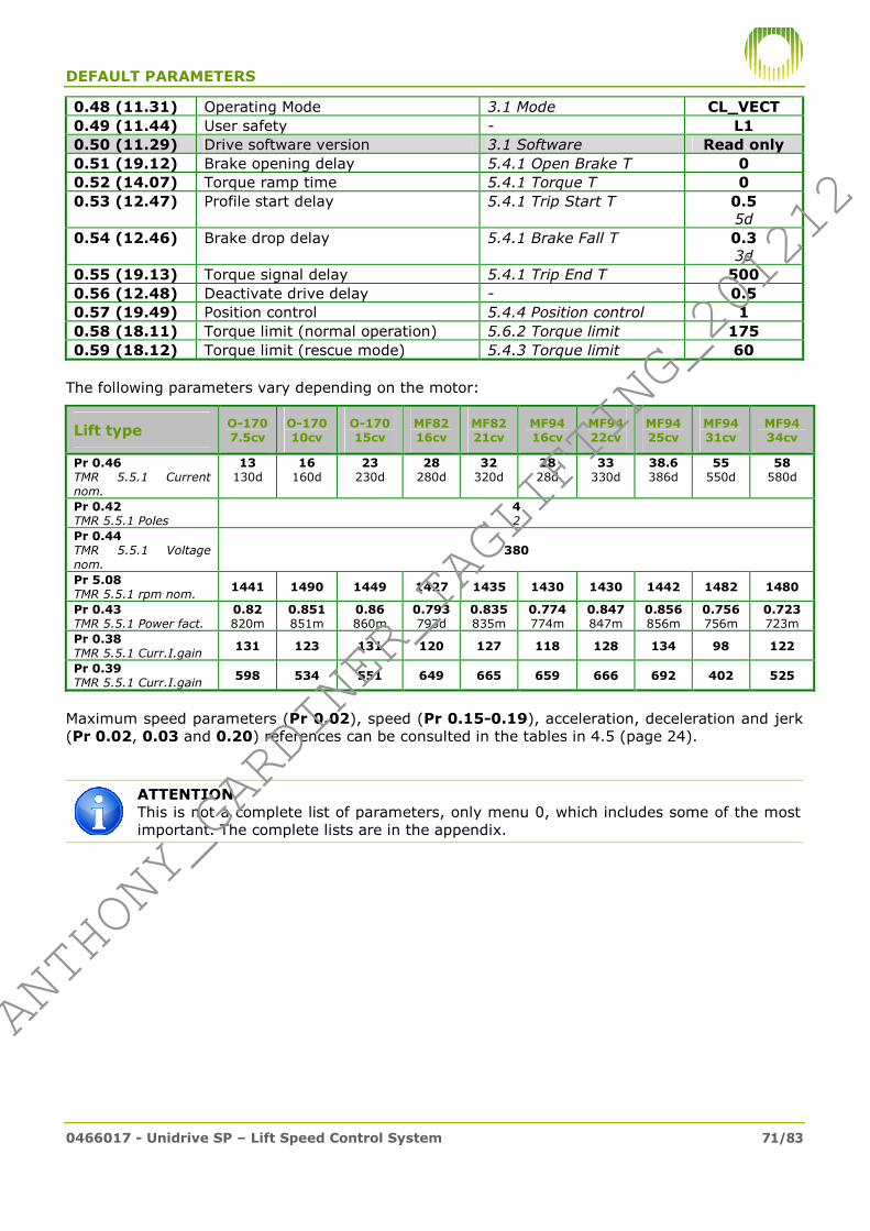
DEFAULT PARAMETERS
0466017 - Unidrive SP – Lift Speed Control System 71/83
0.48 (11.31) Operating Mode 3.1 Mode CL_VECT
0.49 (11.44) User safety - L1
0.50 (11.29) Drive software version 3.1 Software Read only
0.51 (19.12) Brake opening delay 5.4.1 Open Brake T 0
0.52 (14.07) Torque ramp time 5.4.1 Torque T 0
0.53 (12.47) Profile start delay 5.4.1 Trip Start T 0.5 5d
0.54 (12.46) Brake drop delay 5.4.1 Brake Fall T 0.3 3d
0.55 (19.13) Torque signal delay 5.4.1 Trip End T 500
0.56 (12.48) Deactivate drive delay - 0.5
0.57 (19.49) Position control 5.4.4 Position control 1
0.58 (18.11) Torque limit (normal operation) 5.6.2 Torque limit 175
0.59 (18.12) Torque limit (rescue mode) 5.4.3 Torque limit 60
The following parameters vary depending on the motor:
Lift type O-170 7.5cv
O-170 10cv
O-170 15cv
MF82 16cv
MF82 21cv
MF94 16cv
MF94 22cv
MF94 25cv
MF94 31cv
MF94 34cv
Pr 0.46 TMR 5.5.1 Current nom.
13 130d
16 160d
23 230d
28 280d
32 320d
28 28d
33 330d
38.6 386d
55 550d
58 580d
Pr 0.42 TMR 5.5.1 Poles
4 2
Pr 0.44 TMR 5.5.1 Voltage nom.
380
Pr 5.08 TMR 5.5.1 rpm nom. 1441 1490 1449 1427 1435 1430 1430 1442 1482 1480
Pr 0.43 TMR 5.5.1 Power fact.
0.82 820m
0.851 851m
0.86 860m
0.793 793d
0.835 835m
0.774 774m
0.847 847m
0.856 856m
0.756 756m
0.723 723m
Pr 0.38 TMR 5.5.1 Curr.I.gain 131 123 131 120 127 118 128 134 98 122
Pr 0.39 TMR 5.5.1 Curr.I.gain 598 534 551 649 665 659 666 692 402 525
Maximum speed parameters (Pr 0.02), speed (Pr 0.15-0.19), acceleration, deceleration and jerk (Pr 0.02, 0.03 and 0.20) references can be consulted in the tables in 4.5 (page 24).
ATTENTION This is not a complete list of parameters, only menu 0, which includes some of the most important. The complete lists are in the appendix.
#ANTHONY_GARDINER_TAGLIFTING_201212#
ANTHONY_GARDINER_TAGLIFTING_201212

DEFAULT PARAMETERS
0466017 - Unidrive SP – Lift Speed Control System 72/83
BASIC PARAMETERS M33 ORIGINAL
Pr Description Value
0.00 (x.00) Function execution parameter 0
0.01 (1.07) Minimum speed reference 0 0.02 (1.06) Maximum speed reference See table
0.03 (2.11) Acceleration 7.480
0.04 (2.21) Deceleration 7.480
0.05 (1.14) Reference type selector Pr
0.06 (4.07) Output current limit 175
0.07 (3.10) Speed loop Gain P 0.2100
0.08 (3.11) Speed loop Gain I 1.00
0.09 (3.12) Speed loop Gain D 0
0.10 (3.02) Encoder speed reading Read only
0.11 (3.01) Speed reference Read only
0.12 (4.01) Current consumed by motor Read only
0.13 (5.05) DC bus voltage. Read only
0.14 (1.50) Selected speed level Read only
0.15 (1.22) Isoleveling speed 4.0
0.16 (1.23) Floor approximation speed 16.0
0.17 (1.24) Inspection speed 90.0
0.18 (1.25) Intermediate speed V1 191.0
0.19 (1.28) Maximum Speed See table
0.20 (18.27) Jerk during travel 380.0
0.21 (8.02) Door advance opening relay output status Read only
0.22 (8.01) Brake relay output status Read only
0.23 (9.09) Brake drop delay 0.7
0.24 (4.03) Torque demand on motor Read only
0.25 (4.08) Compensation applied by loadweights Read only
0.26 (4.09) Compensation with empty lift See table
0.27 (7.12) Loadweights adjustment See table
0.28 (3.42) Speed reading filter 1 ms
0.29 (8.09) Secure Disable input reading Read only
0.30 (11.42) SmartCard functions parameter 0
0.31 (11.33) Drive rated voltage Read only
0.32 (11.32) Drive rated current Read only
0.34 (11.30) User security code 0
0.35 (11.24) Serial communication protocol rtu
0.36 (11.25) Serial communication speed 19200
0.37 (11.23) Serial communication node no. 1
0.38 (4.13) Current loop Gain P 307
0.39 (4.14) Current loop Gain I 812
0.40 (5.12) Start auto tuning 0
0.41 (5.18) Switching frequency 8 kHz
0.42 (5.11) No. motor poles 12
0.43 (3.25) Encoder reference angle varies
0.44 (5.09) Motor rated voltage 390
0.45 (4.15) Thermal model time constant 20
0.46 (5.07) Motor rated current See table
0.48 (11.31) Operating Mode SERVO
0.49 (11.44) User safety L1
0.50 (11.29) Drive software version Read only
#ANTHONY_GARDINER_TAGLIFTING_201212#
ANTHONY_GARDINER_TAGLIFTING_201212
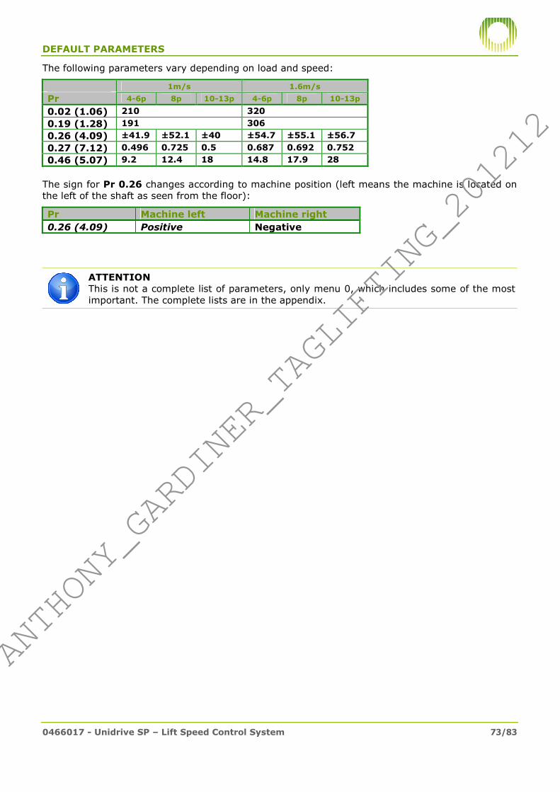
DEFAULT PARAMETERS
0466017 - Unidrive SP – Lift Speed Control System 73/83
The following parameters vary depending on load and speed:
1m/s 1.6m/s
Pr 4-6p 8p 10-13p 4-6p 8p 10-13p
0.02 (1.06) 210 320
0.19 (1.28) 191 306
0.26 (4.09) ±41.9 ±52.1 ±40 ±54.7 ±55.1 ±56.7
0.27 (7.12) 0.496 0.725 0.5 0.687 0.692 0.752
0.46 (5.07) 9.2 12.4 18 14.8 17.9 28
The sign for Pr 0.26 changes according to machine position (left means the machine is located on the left of the shaft as seen from the floor):
Pr Machine left Machine right
0.26 (4.09) Positive Negative
ATTENTION This is not a complete list of parameters, only menu 0, which includes some of the most important. The complete lists are in the appendix.
#ANTHONY_GARDINER_TAGLIFTING_201212#
ANTHONY_GARDINER_TAGLIFTING_201212

DEFAULT PARAMETERS
0466017 - Unidrive SP – Lift Speed Control System 74/83
BASIC PARAMETERS M33 EXTENDED
Pr Description Value
0.00 (x.00) Function execution parameter 0
0.01 (1.07) Minimum speed reference 0 0.02 (1.06) Maximum speed reference See table
0.03 (2.11) Acceleration 5.980
0.04 (2.21) Deceleration 5.980
0.05 (1.14) Reference type selector Pr
0.06 (4.07) Output current limit Read only
0.07 (3.10) Speed loop Gain P 0.1500
0.08 (3.11) Speed loop Gain I 1.00
0.09 (3.12) Speed loop Gain D 0
0.10 (3.02) Encoder speed reading Read only
0.11 (3.01) Speed reference Read only
0.12 (4.01) Current consumed by motor Read only
0.13 (5.05) DC bus voltage. Read only
0.14 (1.50) Selected speed level Read only
0.15 (1.22) Isoleveling speed 5.0
0.16 (1.23) Floor approximation speed 20.0
0.17 (1.24) Inspection speed 112.5
0.18 (1.25) Intermediate speed V1 239.0
0.19 (1.28) Maximum Speed See table
0.20 (2.17) Jerk during travel 2.094
0.21 (18.01) Favourable direction for rescue Read only
0.22 (8.01) Brake relay output status Read only
0.23 (8.03) Rescue mode input state Read only
0.24 (4.03) Torque demand on motor Read only
0.25 (7.02) Loadweights reading level (%) Read only
0.26 (4.09) Compensation with empty lift See table
0.27 (7.12) Loadweights adjustment See table
0.28 (3.42) Speed reading filter 1 ms
0.29 (8.09) Secure Disable input reading Read only
0.30 (11.42) SmartCard functions parameter 0
0.31 (11.33) Drive rated voltage Read only
0.32 (11.32) Drive rated current Read only
0.33 (18.40) Change rotation direction See table
0.34 (18.45) Rescue only in forward direction 1
0.35 (11.24) Serial communication protocol rtu
0.36 (11.25) Serial communication speed 19200
0.37 (11.23) Serial communication node no. 1
0.38 (4.13) Current loop Gain P 212
0.39 (4.14) Current loop Gain I 601
0.40 (5.12) Start auto tuning 0
0.41 (5.18) Switching frequency 8 kHz
0.42 (5.11) No. motor poles 12
0.43 (3.25) Encoder reference angle Varies
0.44 (5.09) Motor rated voltage 390
0.45 (4.15) Thermal model time constant 20
0.46 (5.07) Motor rated current See table
0.48 (11.31) Operating Mode SERVO
0.49 (11.44) User safety L1
0.50 (11.29) Drive software version Read only
#ANTHONY_GARDINER_TAGLIFTING_201212#
ANTHONY_GARDINER_TAGLIFTING_201212

DEFAULT PARAMETERS
0466017 - Unidrive SP – Lift Speed Control System 75/83
0.51 (19.12) Brake opening delay 500
0.52 (14.07) Torque ramp time 0.6
0.53 (12.47) Profile start delay 0.8
0.54 (12.46) Brake drop delay 0.2
0.55 (19.13) Torque signal delay 250
0.56 (12.48) Deactivate drive delay 1.0
0.57 (19.49) Position control 0
0.58 (18.11) Torque limit (normal operation) 175
0.59 (18.12) Torque limit (rescue mode) 100
The following parameters vary depending on load and speed:
1m/s 1.6m/s
Pr 16p 21p 16p 21p
0.02 (1.06) 250 400
0.19 (1.28) 239 383
0.26 (4.09) ±56.6 ±55.8 ±57 ±57.8
0.27 (7.12) 0.711 0.701 0.717 0.698
0.46 (5.07) 20.1 26 32 43.5
The following parameters vary according to machine position (left means the machine is located on the left of the shaft as seen from the floor):
Pr Machine left Machine right
0.26 (4.09) Positive Negative
0.33 (18.40) On Off
ATTENTION This is not a complete list of parameters, only menu 0, which includes some of the most important. The complete lists are in the appendix.
#ANTHONY_GARDINER_TAGLIFTING_201212#
ANTHONY_GARDINER_TAGLIFTING_201212

DEFAULT PARAMETERS
0466017 - Unidrive SP – Lift Speed Control System 76/83
BASIC PARAMETERS M33 OPTIMIZED
Pr Description TMR Value
0.00 (x.00) Function execution parameter - 0
0.01 (1.07) Minimum speed reference - 0 0.02 (1.06) Maximum speed reference See table
0.03 (2.11) Acceleration 5.3 Acceleration 5.98 700m
0.04 (2.21) Deceleration 5.3 Deceleration 5.98 700m
0.05 (1.14) Reference type selector - Pr
0.06 (4.07) Output current limit - Read only
0.07 (3.10) Speed loop Gain P 5.4.2 Gain P. 0.2100 2,100m
0.08 (3.11) Speed loop Gain I 5.4.2 Gain I. 1.00 100c
0.09 (3.12) Speed loop Gain D - 0
0.10 (3.02) Encoder speed reading 3.1 Real Speed Read only
0.11 (3.01) Speed reference - Read only
0.12 (4.01) Current consumed by motor 3.1 Output Current Read only
0.13 (5.05) DC bus voltage. 3.1 Tension BUS Read only
0.14 (1.50) Selected speed level 3.1 Speed Ref. Read only
0.15 (1.22) Isoleveling speed 5.2 V00 3.7 15m
0.16 (1.23) Floor approximation speed 5.2 V0 18.0 75m
0.17 (1.24) Inspection speed 5.2 Vinsp 112.0 470m
0.18 (1.25) Intermediate speed V1 5.2 V1 239.0 1,000m
0.19 (1.28) Maximum Speed 5.2 Vmax See table
0.20 (18.27) Jerk during travel 5.3 Jerk travel 1311 1,000m
0.21 (18.01) Favourable direction for rescue - Read only
0.22 (8.01) Brake relay output status 3.2 Brake Read only
0.23 (8.03) Rescue mode input state 3.2 Rescue Read only
0.24 (4.03) Torque demand on motor 3.1 Torque & sign.
torque Read only
0.25 (7.02) Loadweights reading level (%) 3.2 Loadweight Read only
0.26 (4.09) Compensation with empty lift 5.4.4 Compensation See table
0.27 (7.12) Loadweights adjustment 5.4.4 Adjustment See table
0.28 (3.42) Speed reading filter 5.4.2 Enc. filter 1 ms
0.29 (8.09) Secure Disable input reading 3.1 Secure Disable Read only
0.30 (11.42) SmartCard functions parameter See section 3.3 0
0.31 (11.33) Drive rated voltage - Read only
0.32 (11.32) Drive rated current - Read only
0.33 (18.40) Change rotation direction See section 5 See table
0.34 (18.45) Rescue only in favourable direction 5.4.3 Rescue favour. dir. 1
0.35 (11.24) Serial communication protocol - rtu
0.36 (11.25) Serial communication speed - 19200
0.37 (11.23) Serial communication node no. - 1
0.38 (4.13) Current loop Gain P 5.6.2 Gain.P.curr. See table
0.39 (4.14) Current loop Gain I 5.6.2 Gain.I.curr. See table
0.40 (5.12) Start auto tuning See section 5.2 0
#ANTHONY_GARDINER_TAGLIFTING_201212#
ANTHONY_GARDINER_TAGLIFTING_201212
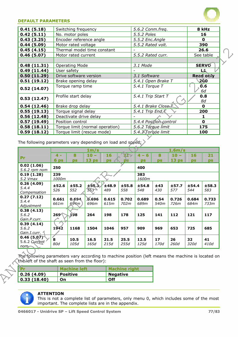
DEFAULT PARAMETERS
0466017 - Unidrive SP – Lift Speed Control System 77/83
0.41 (5.18) Switching frequency 5.6.2 Conm.freq. 8 kHz
0.42 (5.11) No. motor poles 5.5.2 Poles 16
0.43 (3.25) Encoder reference angle 5.5.2 Enc.Angle 0
0.44 (5.09) Motor rated voltage 5.5.2 Rated volt. 390
0.45 (4.15) Thermal model time constant - 26.6
0.46 (5.07) Motor rated current 5.5.2 Rated curr. See table
0.48 (11.31) Operating Mode 3.1 Mode SERVO
0.49 (11.44) User safety - L1
0.50 (11.29) Drive software version 3.1 Software Read only
0.51 (19.12) Brake opening delay 5.4.1 Open Brake T 200
0.52 (14.07) Torque ramp time 5.4.1 Torque T 0.6
6d
0.53 (12.47) Profile start delay 5.4.1 Trip Start T 0.8
8d
0.54 (12.46) Brake drop delay 5.4.1 Brake Close T 0
0.55 (19.13) Torque signal delay 5.4.1 Trip End T 200
0.56 (12.48) Deactivate drive delay - 1
0.57 (19.49) Position control 5.4.4 Position control 0
0.58 (18.11) Torque limit (normal operation) 5.6.2 Torque limit 175
0.59 (18.12) Torque limit (rescue mode) 5.4.3 Torque limit 100
The following parameters vary depending on load and speed:
1m/s 1.6m/s
Pr 4 - 6 ps
8 ps
10 – 13 ps
16 ps
21 ps
4 – 6 ps
8 ps
10 – 13 ps
16 ps
21 ps
0.02 (1.06) 5.6.2 rpm nom
250 400
0.19 (1.28) 5.2 Vmax
239 1000m
383 1600m
0.26 (4.09) 5.4.4
Compensation
±52.6 526
±55.2 552
±55.3 553
±48.9 489
±55.8 558
±54.8 548
±43 430
±57.7 577
±54.4 544
±58.3 583
0.27 (7.12) 5.4.4
Adjustment
0.661 661m
0.694 694m
0.696 696m
0.615 615m
0.702 702m
0.689 689m
0.54 540m
0.726 726m
0.684 684m
0.733 733m
0.38 (4.13) 5.6.2
Gain.P.curr. 269 198 264 198 178 125 141 112 121 117
0.39 (4.14) 5.6.2
Gain.I.curr. 1942 1168 1504 1046 957 909 969 653 725 685
0.46 (5.07) 5.6.2 Current nom.
8 80d
10.5 105d
16.5 165d
21.5 215d
25.5 255d
12.5 125d
17 170d
26 260d
32 320d
41 410d
The following parameters vary according to machine position (left means the machine is located on the left of the shaft as seen from the floor):
Pr Machine left Machine right
0.26 (4.09) Positive Negative
0.33 (18.40) On Off
ATTENTION This is not a complete list of parameters, only menu 0, which includes some of the most important. The complete lists are in the appendix.
#ANTHONY_GARDINER_TAGLIFTING_201212#
ANTHONY_GARDINER_TAGLIFTING_201212

DEFAULT PARAMETERS
0466017 - Unidrive SP – Lift Speed Control System 78/83
M34 BASIC PARAMETERS
Pr Description TMR Value
0.00 (x.00) Function execution parameter - 0
0.01 (1.07) Minimum speed reference - 0 0.02 (1.06) Maximum speed reference 160
0.03 (2.11) Acceleration 5.3 Acceleration 9.72 700m
0.04 (2.21) Deceleration 5.3 Deceleration 9.72 700m
0.05 (1.14) Reference type selector - Pr
0.06 (4.07) Output current limit - Read only
0.07 (3.10) Speed loop Gain P 5.4.2 Gain P. 0.2100 2,100m
0.08 (3.11) Speed loop Gain I 5.4.2 Gain I. 1.00 100c
0.09 (3.12) Speed loop Gain D - 0
0.10 (3.02) Encoder speed reading 3.1 Real Speed Read only
0.11 (3.01) Speed reference - Read only
0.12 (4.01) Current consumed by motor 3.1 Output Current Read only
0.13 (5.05) DC bus voltage. 3.1 Tension BUS Read only
0.14 (1.50) Selected speed level 3.1 Speed Ref. Read only
0.15 (1.22) Isoleveling speed 5.2 V00 2.9 20m
0.16 (1.23) Floor approximation speed 5.2 V0 11.8 80m
0.17 (1.24) Inspection speed 5.2 Vinsp 69.0 469m
0.18 (1.25) Intermediate speed V1 5.2 V1 93.0 630m
0.19 (1.28) Maximum Speed 5.2 Vmax 147.0 1,000m
0.20 (18.27) Jerk during travel 5.3 Jerk travel 2229 1,000m
0.21 (18.01) Favourable direction for rescue - Read only
0.22 (8.01) Brake relay output status 3.2 Brake Read only
0.23 (8.03) Rescue mode input state 3.2 Rescue Read only
0.24 (4.03) Torque demand on motor 3.1 Torque & sign.
torque Read only
0.25 (7.02) Loadweights reading level (%) 3.2 Loadweight Read only
0.26 (4.09) Compensation with empty lift 5.4.4 Compensation 0
0.27 (7.12) Loadweights adjustment 5.4.4 Adjustment 0
0.28 (3.42) Speed reading filter 5.4.2 Enc. filter 1 ms
0.29 (8.09) Secure Disable input reading 3.1 Secure Disable Read only
0.30 (11.42) SmartCard functions parameter See section 3.3 0
0.31 (11.33) Drive rated voltage - Read only
0.32 (11.32) Drive rated current - Read only
0.33 (18.40) Change rotation direction See section 5 See table
0.34 (18.45) Rescue only in favourable direction 5.4.3 Rescue favour. dir. 1
0.35 (11.24) Serial communication protocol - rtu
0.36 (11.25) Serial communication speed - 19200
0.37 (11.23) Serial communication node no. - 1
0.38 (4.13) Current loop Gain P 5.6.2 Gain.P.curr. 475
0.39 (4.14) Current loop Gain I 5.6.2 Gain.I.curr. 1566
#ANTHONY_GARDINER_TAGLIFTING_201212#
ANTHONY_GARDINER_TAGLIFTING_201212

DEFAULT PARAMETERS
0466017 - Unidrive SP – Lift Speed Control System 79/83
0.40 (5.12) Start auto tuning See section 5.2 0
0.41 (5.18) Switching frequency 5.6.2 Conm.freq. 8 kHz
0.42 (5.11) No. motor poles 5.5.2 Poles 16
0.43 (3.25) Encoder reference angle 5.5.2 Enc.Angle 0
0.44 (5.09) Motor rated voltage 5.5.2 Rated volt. 390
0.45 (4.15) Thermal model time constant - 26.6
0.46 (5.07) Motor rated current 5.5.2 Rated curr. See table
0.48 (11.31) Operating Mode 3.1 Mode SERVO
0.49 (11.44) User safety - L1
0.50 (11.29) Drive software version 3.1 Software Read only
0.51 (19.12) Brake opening delay 5.4.1 Open Brake T 200
0.52 (14.07) Torque ramp time 5.4.1 Torque T 0.6 6d
0.53 (12.47) Profile start delay 5.4.1 Trip Start T 0.8 8d
0.54 (12.46) Brake drop delay 5.4.1 Brake Close T 0
0.55 (19.13) Torque signal delay 5.4.1 Trip End T 200
0.56 (12.48) Deactivate drive delay - 1.0
0.57 (19.49) Position control 5.4.4 Position control 1
0.58 (18.11) Torque limit (normal operation) 5.6.2 Torque limit 175
0.59 (18.12) Torque limit (rescue mode) 5.4.3 Torque limit 100
The following parameter varies depending on load:
Load
Pr 4 – 6 ps 8 ps 0.46 (5.07) 5.6.2 Current nom.
8 80d
9.3 93d
ATTENTION This is not a complete list of parameters, only menu 0, which includes some of the most important. The complete lists are in the appendix.
#ANTHONY_GARDINER_TAGLIFTING_201212#
ANTHONY_GARDINER_TAGLIFTING_201212

DEFAULT PARAMETERS
0466017 - Unidrive SP – Lift Speed Control System 80/83
GEARLESS LEROY-SOMER MOTOR BASIC PARAMETERS
Pr Description TMR Value
0.00 (x.00) Function execution parameter - 0
0.01 (1.07) Minimum speed reference - 0 0.02 (1.06) Maximum speed reference See table
0.03 (2.11) Acceleration 5.3 Acceleration 19.8 700m
0.04 (2.21) Deceleration 5.3 Deceleration 19.8 700m
0.05 (1.14) Reference type selector - Pr
0.06 (4.07) Output current limit - Read only
0.07 (3.10) Speed loop Gain P 5.4.2 Gain P. 0.300 300m
0.08 (3.11) Speed loop Gain I 5.4.2 Gain I. 4.00 400c
0.09 (3.12) Speed loop Gain D - 0
0.10 (3.02) Encoder speed reading 3.1 Real Speed Read only
0.11 (3.01) Speed reference - Read only
0.12 (4.01) Current consumed by motor 3.1 Output Current Read only
0.13 (5.05) DC bus voltage. 3.1 Tension BUS Read only
0.14 (1.50) Selected speed level 3.1 Speed Ref. Read only
0.15 (1.22) Isoleveling speed 5.2 V00 1.2 16m
0.16 (1.23) Floor approximation speed 5.2 V0 5.4 75m
0.17 (1.24) Inspection speed 5.2 Vinsp 33.9 470m
0.18 (1.25) Intermediate speed V1 5.2 V1 72.1 1,000m
0.19 (1.28) Maximum Speed 5.2 Vmax See table
0.20 (18.27) Jerk during travel 5.3 Jerk travel 4547 1,000m
0.21 (18.01) Favourable direction for rescue - Read only
0.22 (8.01) Brake relay output status 3.2 Brake Read only
0.23 (8.03) Rescue mode input state 3.2 Rescue Read only
0.24 (4.03) Torque demand on motor 3.1 Torque & sign.
torque Read only
0.25 (7.02) Loadweights reading level (%) 3.2 Loadweight Read only
0.26 (4.09) Compensation with empty lift 5.4.4 Compensation ±77.6
0.27 (7.12) Loadweights adjustment 5.4.4 Adjustment 0.976
0.28 (3.42) Speed reading filter 5.4.2 Enc. filter 1 ms
0.29 (8.09) Secure Disable input reading 3.1 Secure Disable Read only
0.30 (11.42) SmartCard functions parameter See section 3.3 0
0.31 (11.33) Drive rated voltage - Read only
0.32 (11.32) Drive rated current - Read only
0.33 (18.40) Change rotation direction See section 5 See table
0.34 (18.45) Rescue only in forward direction 5.4.3 Rescue favour. dir. 1
0.35 (11.24) Serial communication protocol - rtu
0.36 (11.25) Serial communication speed - 19200
0.37 (11.23) Serial communication node no. - 1
0.38 (4.13) Current loop Gain P 5.6.2 Gain.P.curr. See table
0.39 (4.14) Current loop Gain I 5.6.2 Gain.I.curr. See table
0.40 (5.12) Start auto tuning See section 5.2 0
#ANTHONY_GARDINER_TAGLIFTING_201212#
ANTHONY_GARDINER_TAGLIFTING_201212

DEFAULT PARAMETERS
0466017 - Unidrive SP – Lift Speed Control System 81/83
0.41 (5.18) Switching frequency 5.6.2 Conm.freq. 8 kHz
0.42 (5.11) No. motor poles 5.5.2 Poles 32
0.43 (3.25) Encoder reference angle 5.5.2 Enc.Angle 0
0.44 (5.09) Motor rated voltage 5.5.2 Rated volt. 390
0.45 (4.15) Thermal model time constant - 26.6
0.46 (5.07) Motor rated current 5.5.2 Rated curr. See table
0.48 (11.31) Operating Mode 3.1 Mode SERVO
0.49 (11.44) User safety - L1
0.50 (11.29) Drive software version 3.1 Software Read only
0.51 (19.12) Brake opening delay 5.4.1 Open Brake T 200
0.52 (14.07) Torque ramp time 5.4.1 Torque T 0.6 6d
0.53 (12.47) Profile start delay 5.4.1 Trip Start T 1.0 10d
0.54 (12.46) Brake drop delay 5.4.1 Brake Close T 0.5
5d
0.55 (19.13) Torque signal delay 5.4.1 Trip End T 200
0.56 (12.48) Deactivate drive delay - 1.5
0.57 (19.49) Position control 5.4.4 Position control 0
0.58 (18.11) Torque limit (normal operation) 5.6.2 Torque limit 175
0.59 (18.12) Torque limit (rescue mode) 5.4.3 Torque limit 100
The following parameters vary depending on load and speed:
1m/s 1.6m/s 2.5m/s
Pr 2000kg 1425kg 2000kg 2500kg 1000kg 0.02 (1.06) 5.6.2 Max Rpm
92 135 200
0.19 (1.28) 5.2 Vmax
72,1 1000m
115.3 1599m
180.2 2499m
0.38 (4.13) 5.6.2 Gain.P.curr.
380 173 228 227 173
0.39 (4.14) 5.6.2 Gain.I.curr.
1388 1030 1066 941 1030
0.46 (5.07) 5.6.2 Current nom.
31.3 313d
31.0 310d
46.6 466d
52.0 520d
35 350d
These machines are always configured at Orona as rightwards, and therefore if when installed in the installation they rotate in the wrong direction, they must be inverted with TMR 4.2 Rotation. or Pr 0.33.
If counter movement is present on start, the load compensation must be inverted also (TMR 5.4.4 Comp. sign; or on Keypad Plus changing the sign for Pr 0.26 and Pr 7.13). If there is still counter movement, calibrate the loadweights as described in 4.9.2.
If the motor doesn’t appear in the table, program rated current, rated speed and the number of poles and perform static auto tuning as described in 5.2.2.
ATTENTION This is not a complete list of parameters, only menu 0, which includes some of the most important. The complete lists are in the appendix.
#ANTHONY_GARDINER_TAGLIFTING_201212#
ANTHONY_GARDINER_TAGLIFTING_201212

DEFAULT PARAMETERS
0466017 - Unidrive SP – Lift Speed Control System 82/83
GEARLESS ZIEHL-ABEGG MOTOR BASIC PARAMETERS
Pr Description TMR Valor
0.00 (x.00) Function execution parameter - 0
0.01 (1.07) Minimum speed reference - 0 0.02 (1.06) Maximum speed reference See table
0.03 (2.11) Acceleration 5.3 Acceleration See table
0.04 (2.21) Deceleration 5.3 Deceleration See table
0.05 (1.14) Reference type selector - Pr
0.06 (4.07) Output current limit - Read only
0.07 (3.10) Speed loop Gain P 5.4.2 Gain P. 0.300 300m
0.08 (3.11) Speed loop Gain I 5.4.2 Gain I. 4.00 400c
0.09 (3.12) Speed loop Gain D - 0
0.10 (3.02) Encoder speed reading 3.1 Real Speed Read only
0.11 (3.01) Speed reference - Read only
0.12 (4.01) Current consumed by motor 3.1 Output Current Read only
0.13 (5.05) DC bus voltage. 3.1 Tension BUS Read only
0.14 (1.50) Selected speed level 3.1 Speed Ref. Read only
0.15 (1.22) Isoleveling speed 5.2 V00 See table
0.16 (1.23) Floor approximation speed 5.2 V0 See table
0.17 (1.24) Inspection speed 5.2 Vinsp See table
0.18 (1.25) Intermediate speed V1 5.2 V1 See table
0.19 (1.28) Maximum Speed 5.2 Vmax See table
0.20 (18.27) Jerk during travel 5.3 Jerk travel See table
0.21 (18.01) Favourable direction for rescue - Read only
0.22 (8.01) Brake relay output status 3.2 Brake Read only
0.23 (8.03) Rescue mode input state 3.2 Rescue Read only
0.24 (4.03) Torque demand on motor 3.1 Torque & sign.
torque Read only
0.25 (7.02) Loadweights reading level (%) 3.2 Loadweight Read only
0.26 (4.09) Compensation with empty lift 5.4.4 Compensation ±77.6
0.27 (7.12) Loadweights adjustment 5.4.4 Adjustment 0.976
0.28 (3.42) Speed reading filter 5.4.2 Enc. filter 1 ms
0.29 (8.09) Secure Disable input reading 3.1 Secure Disable Read only
0.30 (11.42) SmartCard functions parameter See section 3.3 0
0.31 (11.33) Drive rated voltage - Read only
0.32 (11.32) Drive rated current - Read only
0.33 (18.40) Change rotation direction See section 5 See table
0.34 (18.45) Rescue only in forward direction 5.4.3 Rescue favour. dir. 1
0.35 (11.24) Serial communication protocol - Rtu
0.36 (11.25) Serial communication speed - 19200
0.37 (11.23) Serial communication node no. - 1
0.38 (4.13) Current loop Gain P 5.6.2 Gain.P.curr. See table
0.39 (4.14) Current loop Gain I 5.6.2 Gain.I.curr. See table
0.40 (5.12) Start auto tuning See section 5.2 0
0.41 (5.18) Switching frequency 5.6.2 Conm.freq. 8 kHz
0.42 (5.11) No. motor poles 5.5.2 Poles 20
0.43 (3.25) Encoder reference angle 5.5.2 Enc.Angle 0
0.44 (5.09) Motor rated voltage 5.5.2 Rated volt. 390
0.45 (4.15) Thermal model time constant - 26.6
0.46 (5.07) Motor rated current 5.5.2 Rated curr. See table
#ANTHONY_GARDINER_TAGLIFTING_201212#
ANTHONY_GARDINER_TAGLIFTING_201212

DEFAULT PARAMETERS
0466017 - Unidrive SP – Lift Speed Control System 83/83
0.48 (11.31) Operating Mode 3.1 Mode SERVO
0.49 (11.44) User safety - L1
0.50 (11.29) Drive software version 3.1 Software Read only
0.51 (19.12) Brake opening delay 5.4.1 Open Brake T 200
0.52 (14.07) Torque ramp time 5.4.1 Torque T 0.6 6d
0.53 (12.47) Profile start delay 5.4.1 Trip Start T 1.0 10d
0.54 (12.46) Brake drop delay 5.4.1 Brake Close T 0.5
5d
0.55 (19.13) Torque signal delay 5.4.1 Trip End T 200
0.56 (12.48) Deactivate drive delay - 1.5
0.57 (19.49) Position control 5.4.4 Position control 0
0.58 (18.11) Torque limit (normal operation) 5.6.2 Torque limit 175
0.59 (18.12) Torque limit (rescue mode) 5.4.3 Torque limit 100
The following table contains motor parameters. If it doesn’t appear, program rated current according to rating plate and perform static auto tuning as described in 0.
Pr 630kg 1ms 1250kg 1ms 1600kg 1ms 2500kg 1ms 1800kg 1.6ms
0.38 (4.13) 5.6.2 Gain.P.curr.
198 880 395 407 395
0.39 (4.14) 5.6.2 Gain.I.curr.
1168 5335 1337 2642 1338
0.46 (5.07) 5.6.2 Current nom.
23.0 230d
30.0 300d
43.0 430d
43.0 430d
54 540d
The following table contains the parameters that depend on installation configuration:
Pulley diam. 320mm 400mm 450mm
Suspension 1:1 2:1 1:1 2:1 2:1
Vel. máx 1ms 1.6ms 1ms 1.6ms 1ms 1.6ms 1ms 1.6ms 1ms 1.6ms
0.02 (1.06) 5.6.2 Max Rpm 70 95 119 191 48 76 95 170 85 136
0.15 (1.22) 5.2 V00
1 17m
1 17m
1.8 15m
1.8 15m
0,7 15m
0.7 15m
1.5 16m
1.5 16m
1.3 15m
1.3 15m
0.16 (1.23) 5.2 V0
4.5 75m
4.5 76m
9 76m
9 75m
3.6 75m
3.6 76m
7.2 76m
7.2 75m
6.5 76m
6.5 76m
0.17 (1.24) 5.2 Vinsp
28 467m
28 472m
56 471m
56 469m
22 458m
22 463m
45 474m
45 471m
40 471m
40 471m
0.18 (1.25) 5.2 V1
60 1000m
60 1011m
119 1000m
119 997m
48 1000m
48 1011m
95 1000m
95 1000m
85 1000m
85 1000m
0.19 (1.28) 5.2 Vmax
60 1000m
95 1600m
119 1000m
191 1600m
48 1000m
76 1600m
95 1000m
156 1600m
85 1000m
136 1600m
0.02 (2.17) 5.3 Acceleration
23.9 700m
12 700m
29.9 700m
15 700m
16.8 700m
0.03 (2.21) 5.3 Deceleration
23.9 700m
12 700m
29.9 700m
15 700m
16.8 700m
0.20 (18.27) 5.3 Jerk travel
5490 1000d
2745 1000d
6863 1000d
3431 1000d
3860 1000d
These machines are always configured at Orona as rightwards, and therefore if when installed in the installation they rotate in the wrong direction, they must be inverted with TMR 4.2 Rotation or Pr 0.33. If counter movement is present on start, the load compensation must be inverted also (TMR 5.4.4 Comp. sign; or on Keypad Plus changing the sign for Pr 0.26 and Pr 7.13). If there is still counter movement, calibrate the loadweights as described in 4.9.2.
ATTENTION This is not a complete list of parameters, only menu 0, which includes some of the most important. The complete lists are in the appendix.
#ANTHONY_GARDINER_TAGLIFTING_201212#
ANTHONY_GARDINER_TAGLIFTING_201212